Electrical Machines-I Lab Dept. of EEE LIST OF...
38
Electrical Machines-I Lab Dept. of EEE Sree Vahini Institute of Science & Technology Tirivuru LIST OF EXPERIMENTS SNo Name of the experiment Date Signature 1 Magnetization Characteristics of DC shunt Generator. Determination of critical field resistance and Critical speed. 2 Load test on DC shunt Generator. Determination of Characteristics 3 Brake test on DC Shunt motor. Determination of Performance curves 4. Load test on DC compound generator. Determination of characteristics 5. Hopkinson’s test on DC shunt Machines. Predetermination of efficiency 6. Swinburne’s test and predetermination of efficiencies as generator and Motor 7. Speed controlling of DC shunt motor by Field and Armature control 8. Break test on DC compound motor. Determination of performance curves 9. Load test on DC series Generator. Determination of characteristics 10. Separation of losses in Dc shunt motor
Transcript of Electrical Machines-I Lab Dept. of EEE LIST OF...

Electrical Machines-I Lab Dept. of EEE
Sree Vahini Institute of Science & Technology Tirivuru
LIST OF EXPERIMENTS
SNo Name of the experiment Date Signature
1 Magnetization Characteristics of DC shunt Generator. Determination of critical field
resistance and Critical speed.
2 Load test on DC shunt Generator. Determination of Characteristics
3 Brake test on DC Shunt motor.
Determination of Performance curves
4. Load test on DC compound generator.
Determination of characteristics
5. Hopkinson’s test on DC shunt Machines.
Predetermination of efficiency
6. Swinburne’s test and predetermination of
efficiencies as generator and Motor
7. Speed controlling of DC shunt motor by Field
and Armature control
8. Break test on DC compound motor.
Determination of performance curves
9. Load test on DC series Generator. Determination
of characteristics
10. Separation of losses in Dc shunt motor

Exp No: Date:
MAGNETIZATION CHARACTERISTICS OF D.C. SHUNT ` GENERATOR
AIM: To obtain the Magnetization Characteristics of D.C. Shunt Generator and to determine its Critical field resistance & Critical speed. APPARATUS REQUIRED:
S No Name of the equipment Type Range Quantity
1 Voltmeter MC (0-300)V 1
2 Ammeter MC (0-10)A 1
3 Rheostat
- 350 Ω/2A 1
4 Switch DPST - 1
5 Tachometer Analog - 1
THEORY :-
Magnetization Characteristics:
The magnetization characteristics shows the relation between the no load generated emf in armature, E0 and the field (or) exciting current If, at a given fixed speed as shown in model graph.
These characteristics are also known as the No load saturation characteristics or Open
circuit characteristics. The shape of these characteristics is practically same for all generators whether separately excited or self excited.
Due to the residual magnetism in the poles, some emf is generated even when If = 0
represented by OD. Hence, the curve starts a little way up.
The slight curvature, DE at the lower end is due to magnetic inertia. It is seen that the
first part of the curve, EC is practically straight. This is due to the fact that at low flux densities, reluctance of iron path being negligible (due to high permeability), total reluctance is given by the air gap reluctance, which is constant. Hence, the flux and consequentially the generated emf are directly proportional to the exciting current.
However at high flux densities, where µ is small, iron path reluctance becomes appreciable and straight relation, CF between Eo and If no longer holds good, i.e.,
saturation of poles start.
Critical resistance:
It is that maximum value of the field resistance, above which the machine fails to excite i.e. there will be no build up of the voltage.
This resistance corresponds to the straight-line position of the magnetization
characteristic because the magnetic circuit does not offer any appreciable reluctance to the magnetic flux.
Critical speed:
It is that speed for which the given shunt field resistance will represent critical field resistance
(OR) It is that minimum value of the speed of the machine below which the machine fails to
excite.
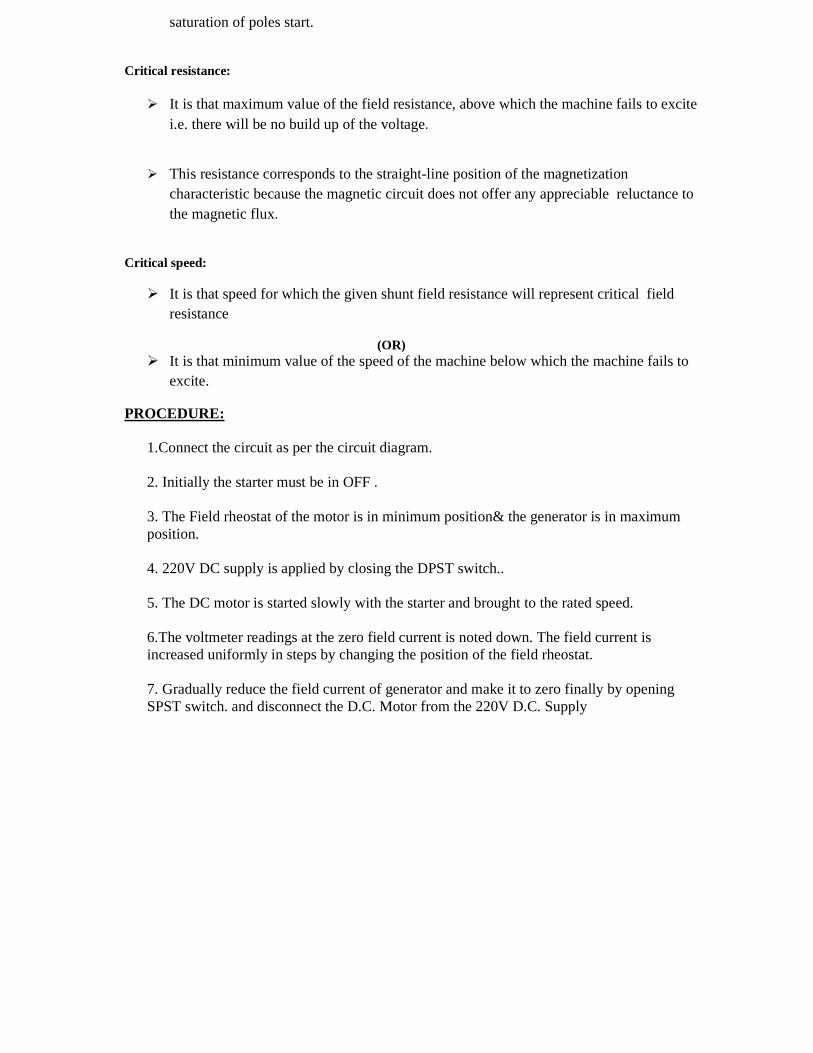
PROCEDURE: 1.Connect the circuit as per the circuit diagram. 2. Initially the starter must be in OFF . 3. The Field rheostat of the motor is in minimum position& the generator is in maximum position. 4. 220V DC supply is applied by closing the DPST switch.. 5. The DC motor is started slowly with the starter and brought to the rated speed. 6.The voltmeter readings at the zero field current is noted down. The field current is increased uniformly in steps by changing the position of the field rheostat. 7. Gradually reduce the field current of generator and make it to zero finally by opening SPST switch. and disconnect the D.C. Motor from the 220V D.C. Supply

CIRCUIT DIAGRAM:

OBSERVATIONS:
MODEL GRAPHS:
CALCULATIONS: TO FIND CRITICAL FIELD RESISTANCE:
1. Plot the magnetization curve.
2. Draw the tangent such that it touches most of the linear part of the curve. 3. This line is the Critical field resistance line. 4. The slope of the above line gives the Critical field resistance.
TO FIND CRITICAL SPEED:
1. Draw the constant field resistance line Rf. 2. From point draw a line on to the Critical field resistance line. Now the Critical speed,
Nc = (AB /AC) ×N, where N is the rated speed of D.C. generator i.e., 1500 rpm.
PRECAUTIONS:
1. The field rheostat of the motor must be kept in minimum & for the generator in maximum positions before switching on the D.C. supply.
2. Ensure that the starter arm is at extreme left position. 3. Avoid loose connections 4. Note down the readings from the meters without any parallax error
RESULT: Critical field resistance = ohms Critical speed = rpm Exp No: Date:
S .no Field current ( I f ) Amp
Armature Voltage ( Eo) Volts

LOAD CHARACTERISTICS OF A DC SHUNT GENERATOR
AIM: To determine the internal and external characteristics of dc shunt generator by performing a load test. APPARATUS REQUIRED:
S .No Name of the equipment Type Range Quantity
1 voltmeter MC (0-300)V 2
2 Ammeter MC (0-10)A 2
3 Switch DPST - -
4 Rheostat
- 350 Ω /2A 1
5 Tachometer
Analog - 1
THEORY :
Generator is run at rated speed and the field current is adjusted to give rated Voltage at no load.
DPST is closed and the load is gradually increased in steps and the readings are recorded at each step. A plot of terminal voltage Vt and load current IL with respect to the particular value of field current If and speed gives the external characteristic curves.
The drop in voltage is due to Ra drop, reduction of main field flux due to armature reaction and further reduction in If
This test is applicable for two similar shunt machines. The two machines are coupled mechanically. One machine runs normally as a motor and drives generator.
PROCEDURE: 1. Connect the circuit as per the circuit diagram. 2. Close the DPST1 switch and start the motor with the help of starter. 3. Adjust the field regulator of the motor till the generator reaches it s rated speed.
4. By adjusting the field regulator of the generator rated voltage can be applied to the generator at its terminals. 5. Apply the load gradually in steps by closing the switch DPST2 and note down the readings of the load current, terminal voltage and field current of the generator for every change in load. 6. Continue the above said procedure until the ammeter shows a reading of near to full load current. 7. Then bring the rheostats to initial positions and switch off the supply
CIRCUIT DIAGRAM:
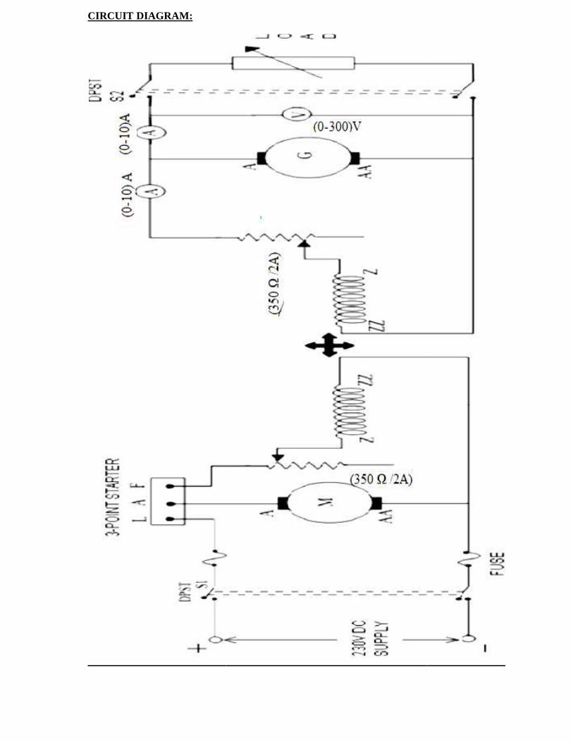
OBSERVATIONS:
MODEL CALCULATIONS: Armature current = load current + field current I a = IL + If Generated emf = terminal voltage + armature resistance drop Eg= Vt +IaRa MODEL GRAPHS: AB drop in field current, BC Armature reaction drop, CD IaRadrop PRECAUTIONS:
1. The field rheostat of the motor must be kept in minimum & for the generator in maximum positions before switching on the D.C. supply.
2. Ensure that the starter arm is at extreme left position. 3. Avoid loose connections 4. Note down the readings from the meters without any parallax error
RESULT Exp No: Date:
S .No Field current, If
Terminal voltage, VT
Load current, IL
Armature current, Ia
Generated emf, Eg

BRAKE TEST ON A D.C. SHUNT MOTOR
AIM: To obtain the Performance characteristics curves of a D.C. shunt motor by conducting brake test on it.
APPARATUS REQUIRED:
S .No Name of the equipment Type Range Quantity
1 Voltmeter
MC (0-300)V 1
2 Ammeter MC (0-20)A 1
3 Rheostat - 350 Ω/2A 1
4. Tachometer Analog - 1
THEORY:
It is a simple method of testing low rating DC machines and consists of applying a brake to a water-cooled drum mounted on the motor shaft.
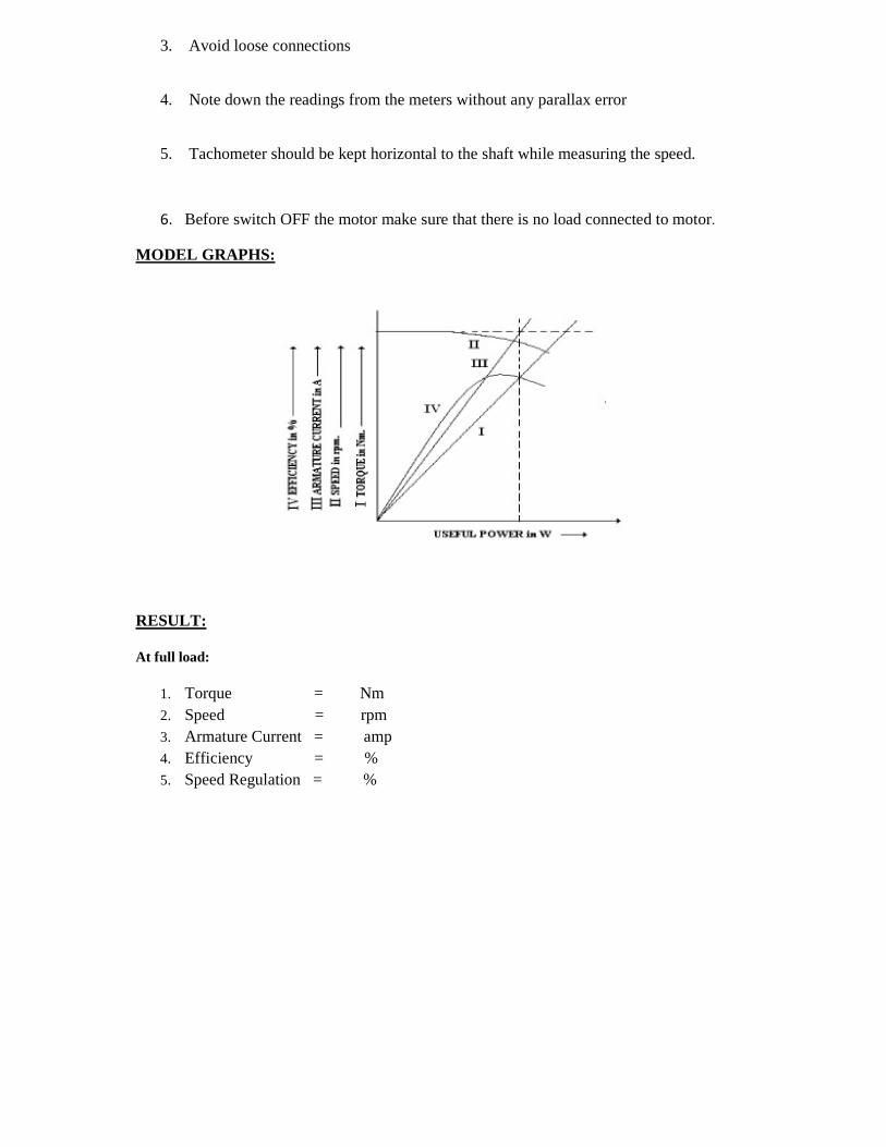
The four important characteristics curves of a D.C. Shunt Motor, namely, Torque, Speed, Armature Current & efficiency, each plotted against the useful Power, as shown in the model graph are known as Performance characteristics.
A belt is wound round the brake drum and its two ends are attached to two spring balances S1 &S2.
The tension of the belt can be adjusted with the help of swivels. The force acting tangentially on the drum is equal to the difference between the readings
of the two spring balances. The net force, F applied on the brake drum is 9.81(S1 S2)*r Newton’s
where , S1 & S2 are the readings of Spring balances 1& 2 in Kg. Shaft torque T, developed by the motor is 9.81 (S1 S2) R Nm where, R is the radius of
the pulley in meters & N is the speed in rpm Useful Output Power = (2 N T) / 60 Watts % Efficiency , = (Output power / Input power) x100 Input Power = V IL Watts, where IL = (Ia + Ish) Speed Regulation (up) = [(No Load speed )-( Full load speed )] / Full Load. The size of the motor that can be tested by this method is limited from the consideration
of the heat that can be dissipated at the brake drum Where the output power exceeds about 2 H.P., or where the test is of long duration, its
necessary to use a water cooled brake drum.
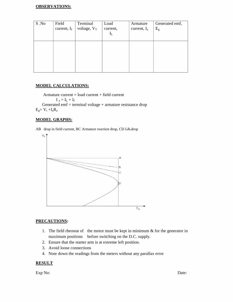
CIRCUIT DIAGRAM:
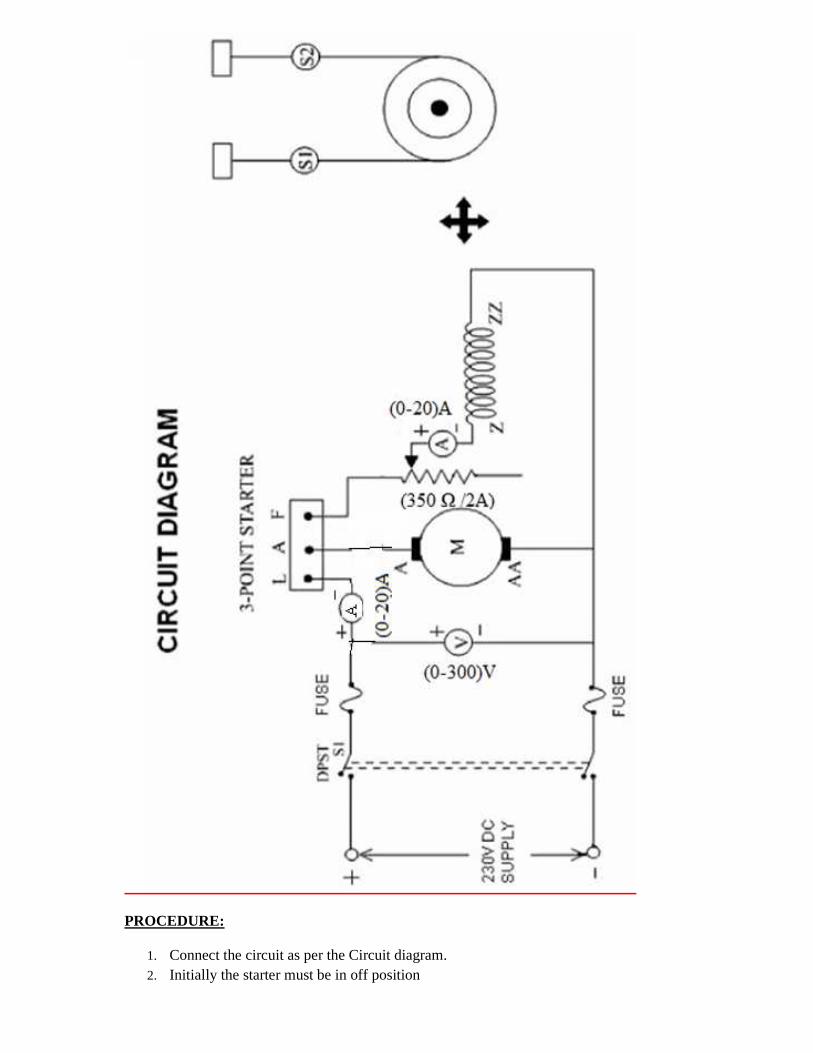
PROCEDURE:
1. Connect the circuit as per the Circuit diagram. 2. Initially the starter must be in off position
3. Switch on the D.C. Motor to 220V D.C. Supply by closing the DPST Switch. 4. Start the D.C. motor using the three point starter and thereby adjust the speed to its rated
speed using field rheostat. 5. Note down the readings of Voltmeter & Ammeters in Table under No Load condition. 6. Apply the Load on the drum gradually in steps by tightening the belt around it. 7. At each step, note down the readings of the Ammeters, Voltmeter, two Spring
balances and the Tachometer. 8. Pour water in the pulley and cool it often when the motor is loaded. 9. Motor from 220V D.C. Supply by opening the DPST Switch
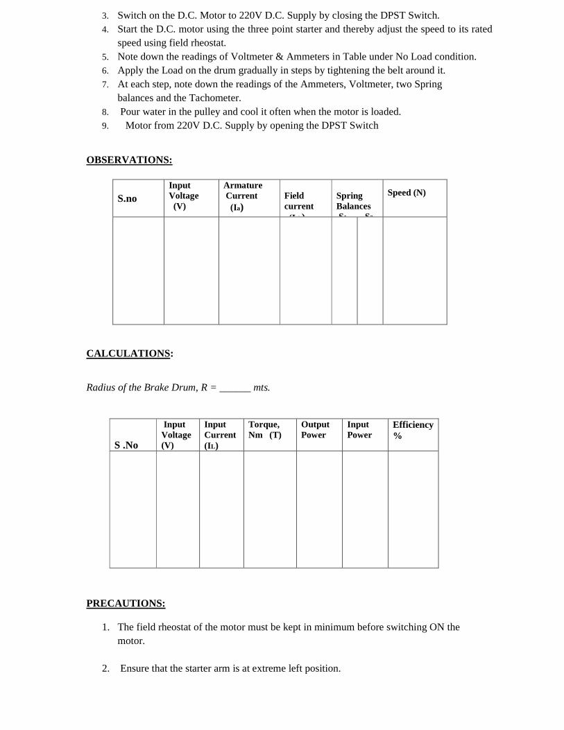
OBSERVATIONS:
S.no Input Voltage (V)
Armature Current (Ia)
Field current (I sh)
Spring Balances S1 S2
Speed (N)
CALCULATIONS : Radius of the Brake Drum, R = ______ mts.
PRECAUTIONS:
1. The field rheostat of the motor must be kept in minimum before switching ON the motor.
2. Ensure that the starter arm is at extreme left position.
S .No
Input Voltage (V)
Input Current (IL)
Torque, Nm (T)
Output Power
Input Power
Efficiency %
3. Avoid loose connections
4. Note down the readings from the meters without any parallax error
5. Tachometer should be kept horizontal to the shaft while measuring the speed.
6. Before switch OFF the motor make sure that there is no load connected to motor.
MODEL GRAPHS:
RESULT: At full load:
1. Torque = Nm 2. Speed = rpm 3. Armature Current = amp 4. Efficiency = % 5. Speed Regulation = %
Exp No: Date:
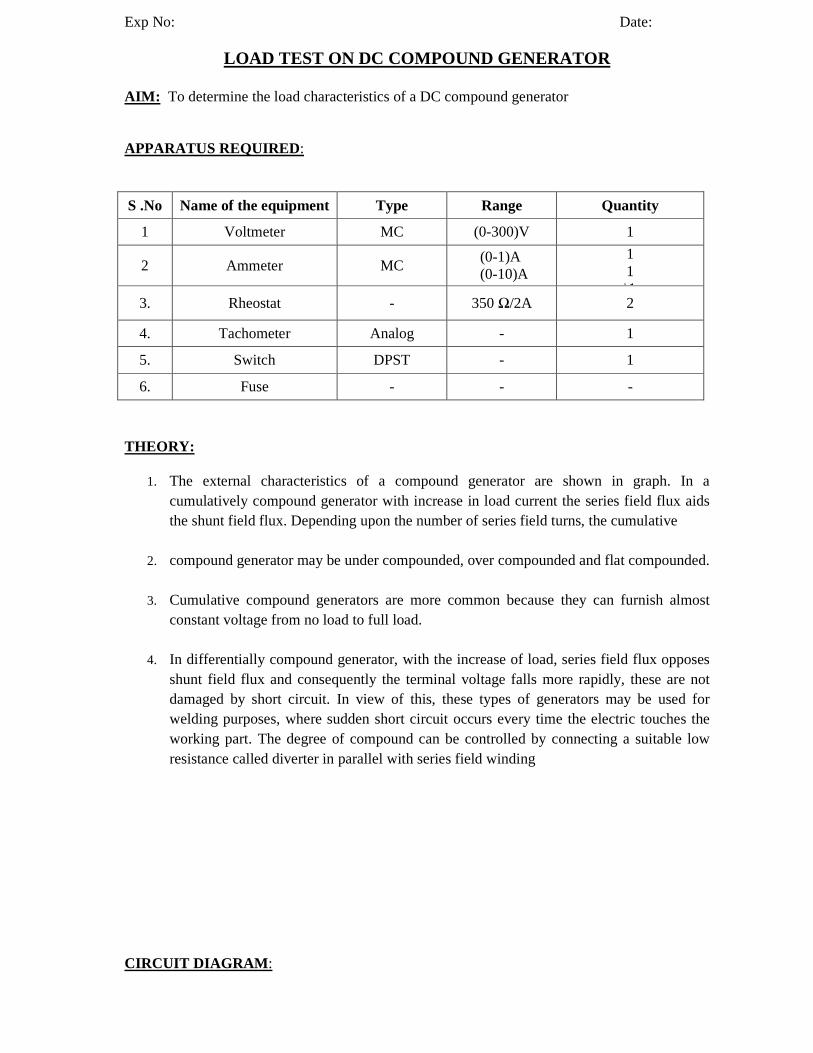
LOAD TEST ON DC COMPOUND GENERATOR
AIM: To determine the load characteristics of a DC compound generator
APPARATUS REQUIRED :
S .No Name of the equipment Type Range Quantity
1 Voltmeter MC (0-300)V 1
2 Ammeter MC (0-1)A (0-10)A
1 1 \1
3. Rheostat - 350 Ω/2A 2
4. Tachometer Analog - 1
5. Switch DPST - 1
6. Fuse - - -
THEORY:
1. The external characteristics of a compound generator are shown in graph. In a cumulatively compound generator with increase in load current the series field flux aids the shunt field flux. Depending upon the number of series field turns, the cumulative
2. compound generator may be under compounded, over compounded and flat compounded.
3. Cumulative compound generators are more common because they can furnish almost constant voltage from no load to full load.
4. In differentially compound generator, with the increase of load, series field flux opposes shunt field flux and consequently the terminal voltage falls more rapidly, these are not damaged by short circuit. In view of this, these types of generators may be used for welding purposes, where sudden short circuit occurs every time the electric touches the working part. The degree of compound can be controlled by connecting a suitable low resistance called diverter in parallel with series field winding
CIRCUIT DIAGRAM :
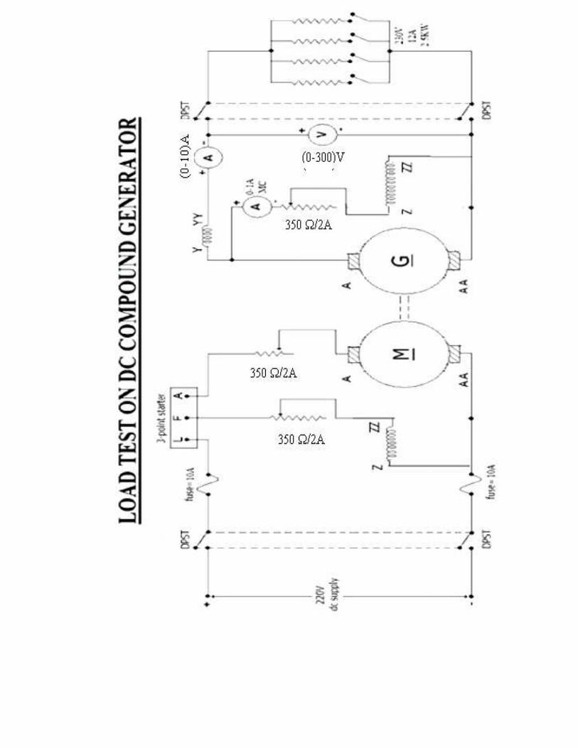
PROCEDURE:
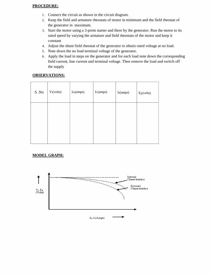
1. Connect the circuit as shown in the circuit diagram. 2. Keep the field and armature rheostats of motor in minimum and the field rheostat of
the generator in maximum. 3. Start the motor using a 3-point starter and there by the generator. Run the motor to its
rated speed by varying the armature and field rheostats of the motor and keep it constant
4. Adjust the shunt field rheostat of the generator to obtain rated voltage at no load. 5. Note down the no load terminal voltage of the generator. 6. Apply the load in steps on the generator and for each load note down the corresponding
field current, line current and terminal voltage. Then remove the load and switch off the supply
OBSERVATIONS:
S .No V t(volts)
Ish(amps)
IL(amps)
Ia(amps)
Eg(volts)
MODEL GRAPH:
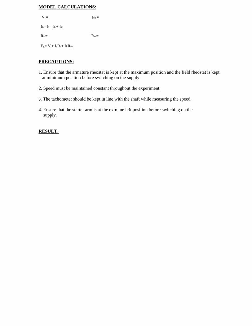
MODEL CALCULATIONS: Vt = Ish = IL =Ia= IL + Ish Ra = Rse= Eg= Vt+ IaRa+ ILRse PRECAUTIONS: 1. Ensure that the armature rheostat is kept at the maximum position and the field rheostat is kept
at minimum position before switching on the supply 2. Speed must be maintained constant throughout the experiment. 3. The tachometer should be kept in line with the shaft while measuring the speed. 4. Ensure that the starter arm is at the extreme left position before switching on the supply. RESULT:
Exp No: Date:
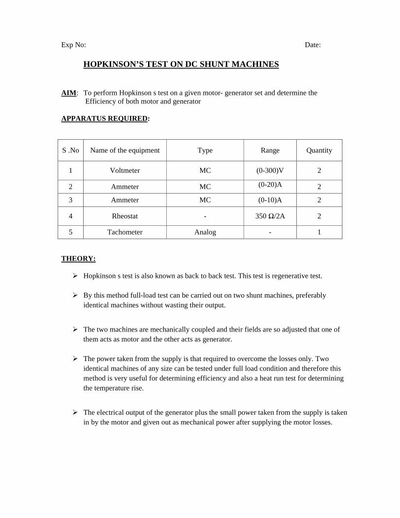
HOPKINSON’S TEST ON DC SHUNT MACHINES
AIM : To perform Hopkinson s test on a given motor- generator set and determine the Efficiency of both motor and generator APPARATUS REQUIRED:
S .No Name of the equipment Type Range Quantity
1 Voltmeter MC (0-300)V 2
2 Ammeter MC (0-20)A
2
3 Ammeter MC (0-10)A 2
4 Rheostat - 350 Ω/2A 2
5 Tachometer Analog - 1
THEORY:
Hopkinson s test is also known as back to back test. This test is regenerative test.
By this method full-load test can be carried out on two shunt machines, preferably identical machines without wasting their output.
The two machines are mechanically coupled and their fields are so adjusted that one of
them acts as motor and the other acts as generator.
The power taken from the supply is that required to overcome the losses only. Two identical machines of any size can be tested under full load condition and therefore this method is very useful for determining efficiency and also a heat run test for determining the temperature rise.
The electrical output of the generator plus the small power taken from the supply is taken
in by the motor and given out as mechanical power after supplying the motor losses.
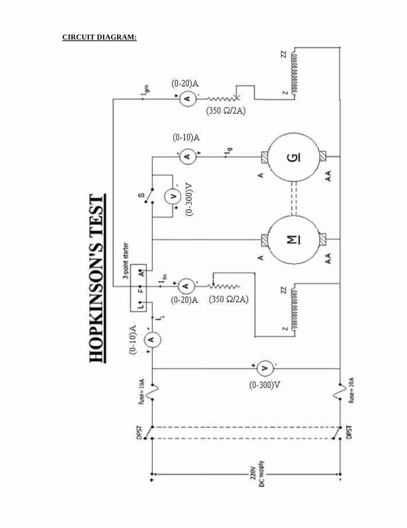
CIRCUIT DIAGRAM:

PROCEDURE:
1. Connect the circuit as per the circuit diagram. 2. Keep the field rheostats of motor, generator at minimum and maximum positions
respectively. 3. Close the DPST switch and open the switch. 4. Start the motor using the 3-point starter and adjust the speed to the rated value.
5. Build up the voltage across the generator by adjusting the field current till the Voltmeter across switch S2 is zero then close the switch S2.
6. Note down the readings of all the ammeters and voltmeters.
7. Switch off the DC supply. OBSERVATIONS: S .No VT(v) IL(A) I fm(A) Iag(A) I fg(A) VG(V)
MODEL CALCULATIONS :
Generator field copper losses Power drawn from the supply Total stray losses (Wc) Stray losses per machine
=V = Ram = Rag = Iam = Iag = Ifm = Ifg = IL = I2am Ram = V Ifm = I2ag Rag
Supply voltage Motor armature resistance Generator armature resistance Motor armature current Generator armature current Motor field current Generator field current Current taken from supply Motor armature copper losses Motor field copper losses Generator armature copper losses
= V Ifg = V IL = VIL (Iam2 Ram+ Iag2 Rag+ V Ifm+ V Ifg) = Wc/ 2
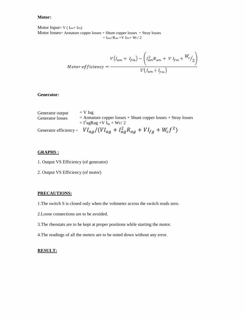
Motor: Motor Input= V ( Iam+ Ifm) Motor losses= Armature copper losses + Shunt copper losses + Stray losses = Iam2 Ram +V I fm+ Wc/ 2
Generator:
Generator efficiency = /( + + + )
GRAPHS : 1. Output VS Efficiency (of generator) 2. Output VS Efficiency (of motor) PRECAUTIONS: 1.The switch S is closed only when the voltmeter across the switch reads zero. 2.Loose connections are to be avoided. 3.The rheostats are to be kept at proper positions while starting the motor. 4.The readings of all the meters are to be noted down without any error. RESULT:
= V Iag = Armature copper losses + Shunt copper losses + Stray losses = I2agRag +V Ifg + Wc/ 2
Generator output Generator losses

Exp No: Date:
SWINBURNE’S TEST AIM: To Pre-determine the efficiency and performance characteristics of a DC Shunt machine. (both as a generator & motor).
APPARATUS REQUIRED :
S .No Name of the equipment Type Range Quantity
1 voltmeter MC (0-300)V 1
2 Ammeter MC (0-2)A 1
3 Ammeter MC (0-10)A 1
4 Switch DPST - 1
5 Tachometer Analog - 1
.6. Rheostat - 350 Ω/2A 1
THEORY:
It is a simple method in which losses are measured separately and from their Knowledge, efficiency at any load can be pre-determined in advance. The only running test needed is a no load test.
Swinburne s test is applicable to those machines in which flux is practically constant i.e. Shunt wound and Compound wound machines.
The machine is running as a motor on no-load at its rated voltage and its speed be adjusted to its rated value using Shunt regulator
The no-load armature current Iao is measured using an ammeter, where as shunt Field current Ish is given by another ammeter. The no-load input current is given
by Io = Iao + Ish
Let the supply voltage be V volts
No-load input =V Io watts Power input to armature =V Iao watts Power input to shunt = V Ishwatts

No-load input supplies Copper losses (Armature & Field), Iron losses (Hysteresis & Eddy current) & Mechanical losses ( Friction losses & Windage). Constant losses = No load input power- Armature copper losses
Wc=V I o – Iao² Ra watts . Predetermination of efficiency of a motor at any load Input = VI watts
Armature Cu losses = I2a Ra Constant losses = Wc Total losses = Wc+ ( I - Ish)² Ra = (input -total losses)/input Predetermination of efficiency of a generator at any load Output = VI watts Armature Cu losses = I2a Ra Constant losses = Wc
Total losses = Wc+ ( I + Ish)² Ra
= output/(output +losses) Maximum Efficiency :Variable losses (Ia² Ra) = Constant losses ( Wc) PROCEDURE: 1. Connect the circuit as per the Circuit diagram. 2. Initially the starter must be in off position. 3. Switch on the D.C. Motor to 220V D.C. Supply by closing the DPST Switch. 4. Start the D.C. motor using the three point starter and thereby adjust the speed to its rated speed using field rheostat. 5. Note down the readings of Voltmeter & Ammeters in Table 6. Switch off the D.C. Motor from 220V D.C. Supply by opening the DPST Switch. CIRCUIT DIAGRAM:
I

OBSERVATIONS:

S .No Input Voltage (V) Armature Current (A) Field current(A)
CALCULATION TABLE: For Motor:
S .no
Input Voltage (v)
Input current (I)
Armature copper losses
Total losses
Input power
Output power
%efficiency
Generator:
S .no
Input Voltage (v)
Load current (I)
Armature current (Ish)
Constant copper losses
Total losses
Input power
Output power
%efficiency
MODEL GRAPH:
PRECAUTIONS: 1. The field rheostat of the motor must be kept in minimum before switching on the 220V D.C. supply. 2. Ensure that the starter arm is at extreme left position. 3. Avoid loose connections 4. Note down the readings from the meters without any parallax error RESULT: Exp No: Date:
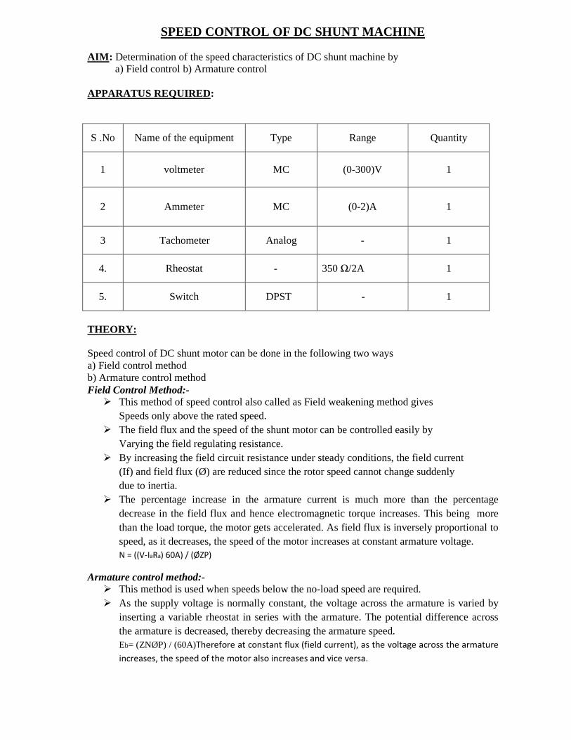
SPEED CONTROL OF DC SHUNT MACHINE
AIM : Determination of the speed characteristics of DC shunt machine by
a) Field control b) Armature control APPARATUS REQUIRED:
S .No Name of the equipment Type Range Quantity
1 voltmeter MC (0-300)V 1
2 Ammeter MC (0-2)A 1
3 Tachometer Analog - 1
4. Rheostat - 350 Ω/2A 1
5. Switch DPST - 1
THEORY: Speed control of DC shunt motor can be done in the following two ways a) Field control method b) Armature control method Field Control Method:-
This method of speed control also called as Field weakening method gives Speeds only above the rated speed.
The field flux and the speed of the shunt motor can be controlled easily by Varying the field regulating resistance.
By increasing the field circuit resistance under steady conditions, the field current (If) and field flux (Ø) are reduced since the rotor speed cannot change suddenly due to inertia.
The percentage increase in the armature current is much more than the percentage decrease in the field flux and hence electromagnetic torque increases. This being more than the load torque, the motor gets accelerated. As field flux is inversely proportional to speed, as it decreases, the speed of the motor increases at constant armature voltage. N = ((V-IaRa) 60A) / (ØZP)
Armature control method:- This method is used when speeds below the no-load speed are required. As the supply voltage is normally constant, the voltage across the armature is varied by
inserting a variable rheostat in series with the armature. The potential difference across the armature is decreased, thereby decreasing the armature speed. Eb= (ZNØP) / (60A)Therefore at constant flux (field current), as the voltage across the armature
increases, the speed of the motor also increases and vice versa.
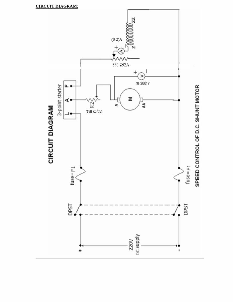
CIRCUIT DIAGRAM :

PROCEDURE:
1. Connect the circuit as shown in the circuit diagram.
2. Keep the armature rheostat at maximum position and the field rheostat at minimum position before starting the experiment.
3. The DC supply is switched ON and motor is started with the help of a three point Starter. 4. Keep the field current constant and vary the rheostat in series with the armature. 5. Note down the corresponding readings of the voltmeter across the armature and Speed of the
DC shunt motor.
6.Now the rheostat of the armature is kept as it is and now the field rheostat is varied and note down the corresponding readings of field current and the speed of the DC shunt motor.
OBSERVATIONS: FIELD CONTROL METHOD: At Va =
I f(A) speed N(rpm)
ARMATURE CONTROL METHOD: At If =
Voltage(V) Speed N(rpm)
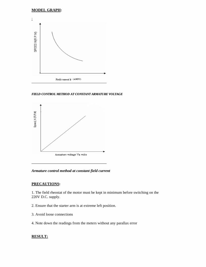
MODEL GRAPH : :
FIELD CONTROL METHOD AT CONSTANT ARMATURE VOLTAGE
Armature control method at constant field current PRECAUTIONS: 1. The field rheostat of the motor must be kept in minimum before switching on the 220V D.C. supply. 2. Ensure that the starter arm is at extreme left position. 3. Avoid loose connections 4. Note down the readings from the meters without any parallax error RESULT:
Exp No: Date:
BRAKE TEST ON A DC COMPOUND MOTOR
AIM : To perform Brake test on a given D.C. Compound motor and obtain the performance characteristics of the motor. APPARATUS REQUIRED : S.No Name of the equipment Type Range Quantity
1 Ammeter MC (0-20)A 1
2 Voltmeter MC (0-300)V 1
3 Tachometer Analog - 1
4 Rheostat - 350 Ω/2A 1
THEORY : It is a direct method and consists of applying brake to a water cooled pulley mounted on the motor shaft. The simple brake test can be used for small motors only. Because, in case of large motors, it is difficult to dissipate the large amount of heat generated at the brake. The simple method of measuring motor output is by the use of pulley brake method. A rope is wound round the pulley and its two ends are attached to two spring balances S1 & S2. The tension of the rope can be adjusted with the help of swivels. The force acting tangentially on the pulley is equal to the difference between the two spring balances. If r is the pulley radius, then torque at the pulley is Tsh=(S1~S2)r. Motor output = Tsh =9.81*r *(S1-S2) PROCEDURE:
1. Connect the circuit as shown in the circuit diagram. 2. Decrease the field regulating variable resistor of motor to a minimum value. Put ON the DPST switch. 3.Using a 4-point starter start the motor and bring it to a rated speed. 4. Note all the readings at no- load i.e., the terminal voltage, load current and speed of the motor. 5. Now tighten the belt of the pulley so that the load increases gradually. While doing this, note again all the above readings mentioned and also the spring balance readings. 6. Pour water into the pulley and cool it whenever the motor is loaded heavily and see that the drum of the pulley does not get much heated. 7. Run the motor till the full load is reached and now release the load slowly and stop the motor by switching OFF the DPST switch

CIRCUIT DIAGRAM:
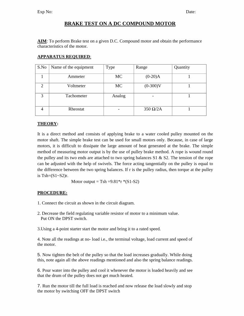
OBSERVATIONS:
S.No Line
current Ip
Weights Terminal voltage
(V)
Speed N
(rpm)
Torque(T) = 9.81(S1~S2)r (N-m)
Input PowerPi=V IL (Watts)
Output Power
pou=t
%Efficiency S1 S2
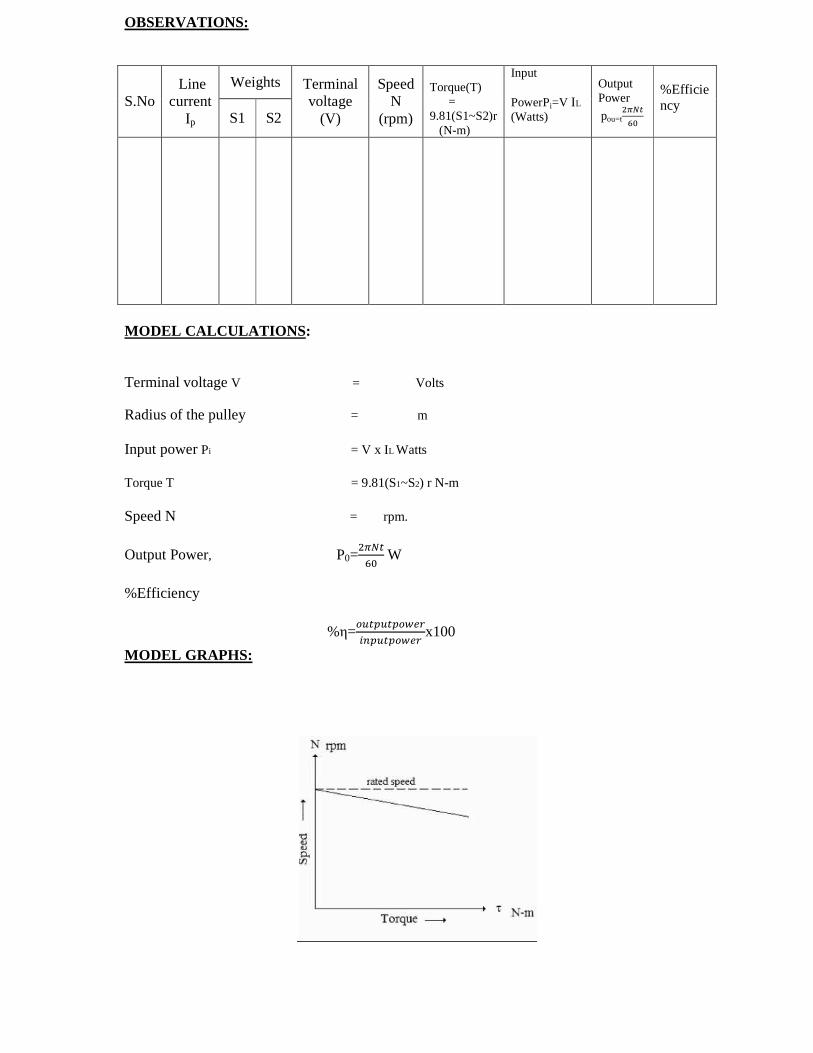
MODEL CALCULATIONS : Terminal voltage V = Volts Radius of the pulley = m Input power Pi = V x IL Watts Torque T = 9.81(S1~S2) r N-m Speed N = rpm.
Output Power, P0=
W
%Efficiency
%η=
x100
MODEL GRAPHS:

PRECAUTIONS:
1. Loose connections must be avoided to prevent from short-circuits. 2. Starter should be operated gently and the brake should be slowly applied in steps to avoid over loading. 3. See that the drum of the pulley does not get much heated by pouring water.
.
RESULT:
Exp No: Date:
LOAD TEST ON DC SERIES GENERATOR
AIM : To perform load test on a DC series generator and to draw the internal and external characteristics.
APPARATUS REQUIRED:
S.No Name of the equipment Type Range Quantity
1 Voltmeter MC (0-300)V 1
2 Ammeter MC (0-10)A 1
3 Rheostat - 350 Ω/2A 1
4 Tachometer Analog - 1
THEORY : NO-LOAD CHARACTERISTICS : In a DC series generator the armature winding and field winding and load resistance are connected in series, therefore the field current is equal to the armature or load current. In view of this, even though the series field current is zero the generator will build some voltage which is due to residual flux and is known as residual voltage and it is very low when the load is opened. However if the generator terminals are closed, through the load rheostat the armature current will flow. This improves the residual flux and then residual voltage. The magnetization curve at one speed for a series generator is illustrated by curve 1. EXTERNAL CHARACTERISTICS (Eg Vs Ia): This is known as total characteristics which give the relation between EMF actually induced in armature and armature current.When the load side switch is open, the small voltage due to residual flux will be indicated by the voltmeter. When that switch is closed field current equal to load current starts flowing. If the current in series field produces a flux aiding the residual flux, the generator will build up voltage till point C is reached. At point C the field resistance line OC meets the saturation curve. The field resistance line OC depends on the total resistance in series circuit i.e., it implies the slope of the line OC is determined by the sum of the armature circuit resistance, series field resistance and load resistance. If the total resistance is more than the critical field resistance, just like a self-excited shunt generator, the buildup process will not begin. Increase the load on dc series generator in steps and at each step, record load voltage and load current. A curve passing through these plotted points gives external characteristic of curve 2. In the figure shown AB is load voltage or armature terminal voltage for a load current of OA.
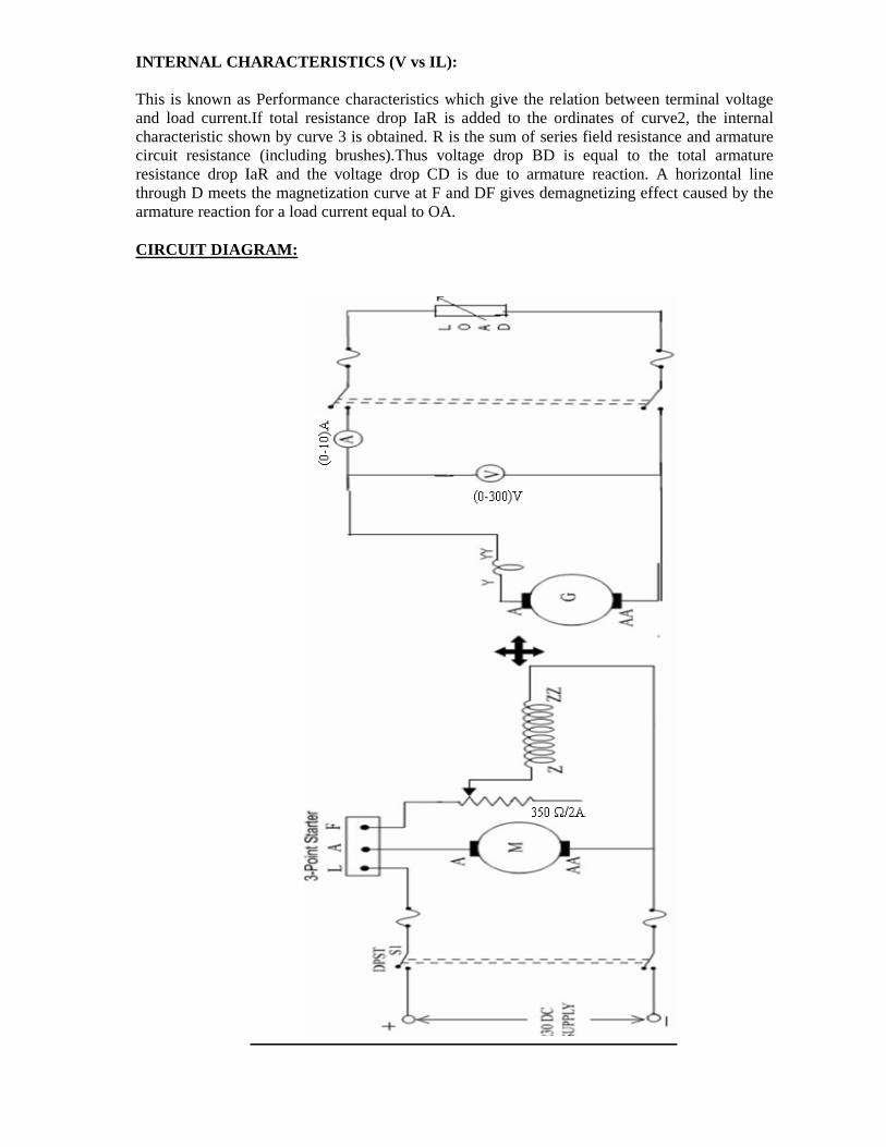
INTERNAL CHARACTERISTICS (V vs IL): This is known as Performance characteristics which give the relation between terminal voltage and load current.If total resistance drop IaR is added to the ordinates of curve2, the internal characteristic shown by curve 3 is obtained. R is the sum of series field resistance and armature circuit resistance (including brushes).Thus voltage drop BD is equal to the total armature resistance drop IaR and the voltage drop CD is due to armature reaction. A horizontal line through D meets the magnetization curve at F and DF gives demagnetizing effect caused by the armature reaction for a load current equal to OA. CIRCUIT DIAGRAM:

PROCEDURE: 1.Connect the circuit as shown in the circuit diagram. 2. Start the DC shunt motor using 3-point starter and adjust its speed with the help of its field Rheostat to the rated speed of generator. 3. Note down the reading of voltage generated across the armature of generator at the corresponding load current. 4. Now switch on the load in steps and note down the corresponding readings of load current and terminal voltage maintaining at rated speed. 5. The procedure is repeated until the rated current is reached. 6. Reduce the load to zero and switch off the load. 7. Make all the Rheostats to its initial positions and then switch off the DC Supply. OBSERVATIONS:
MODEL GRAPH :
MODEL CALCULATIONS: IL = Load current IA = Armature current V = Terminal Voltage Eg = Generated EMF = V+ IL(Ra+Rse) PRECAUTIONS: 1. The connections should be tight and clear. 2. Before starting the DC machine, the armature and field rheostats should be kept at maximum and minimum positions. RESULT:
S.No
Terminal Voltage, Vt (Volts)
Load current, IL
(Amp)
Eg(Volts)

Exp No: Date:
SEPARATION OF LOSSES IN D.C. MACHINE
AIM: To perform suitable test on the given D.C. shunt machine for the determination of losses APPARATUS REQUIRED :
S.No Name of the equipment Type Range Quantity
1 Voltmeter MC (0-300)V 1
2 Ammeter MC (0-10)A 2
3 Tachometer Analog - 1
4. Rheostat - 350 Ω/2A 1
THEORY : D.C. machine consist the following losses. 1. Copper losses 2. Rotational losses
Copper loss consists of armature copper loss and field copper loss. Rotational losses consists of iron losses, mechanical losses and stray load losses.
Iron loss again subdivided into hysteresis loss and eddy current loss. By performing no- load test on D.C. Shunt machine at different fixed field currents all the above losses can be separated.
PROCEDURE:
1. The connections are made as per the circuit diagram. 2. The motor is started slowly using the starter keeping the field and armature rheostats in
minimum and maximum positions respectively. 3. The field current is adjusted to the rated value at no-load. 4. The armature circuit resistance is reduced in steps while increasing the speed. 5. The readings of the voltmeter, ammeter and tachometer are taken at constant field current 6. The experiment is continued till the maximum speed is obtained by cutting out the
complete resistance in armature circuit 7. The armature rheostat is brought back to its initial minimum position. The motor is
stopped. 8. The armature resistance is measured using a multi meter. 9. The readings are tabulated.

CIRCUIT DIAGRAM:
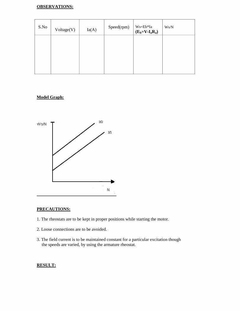
OBSERVATIONS:
S.No
Voltage(V)
Ia(A)
Speed(rpm)
Ws=Eb*Ia (Eb=V-I aRa)
Ws/N
Model Graph:
PRECAUTIONS: 1. The rheostats are to be kept in proper positions while starting the motor. 2. Loose connections are to be avoided. 3. The field current is to be maintained constant for a particular excitation though
the speeds are varied, by using the armature rheostat. RESULT: