Electrical Machines are Electromechanical energy converson ...
34
Transcript of Electrical Machines are Electromechanical energy converson ...

Outlines:
Introduction
Types of Electrical Machines
Types of 3-Ph induction motor
Basic Principle
Working Principle
Compnents of induction motor
Application
Comparision between 1-ph I.M. & 3-ph I.M.
Electrical Machines are Electromechanical energy converson devices.
Electrical motor coverts electrical energy into mechanical energy and electrcal generators are vice versa.
Most of the Industrial load are inductive, especially 3-ph induction motors are widely used in industrial
applications for continious operation.
1.AC Machines 2.DC Machines
AC Machines:-
1-Ph Induction Motor
3-Ph Induction Motor
Synchronous motor
1- Ph Transformer
3-ph Transformer
Altrnator or AC Generator

DC Machines:-
-DC Motor
-DC Generator
DC Motor:
DC Shunt Motor
DC Series Motor
DC Compound Wound Motor
DC Generator
DC Shunt Generator
DC Series Generator
DC Compound Wound Generator
A Rotating Magnetic field (RMF) is set up in the stator when a 3- Phase supply is given.
The stationary rotor cut the revolving field and due to electromagnetic induction an e.m.f. is induced in the rotor conductor.
As the rotor conductor is short circuited current flows through them.
It becomes a current carrying conductor in magnetic field and start rotating.
Principle of Operation

Induction motor rotor always rotate at a speed less than
synchronous speed.
The difference between the flux (Ns) and the rotor speed (N) is called slip.
% Slip (s) = N
s – N
Ns
*100
Where Ns=Synchronous Speed N= Actual Speed of rotor
Slip speed = Ns – N
Slip of an Induction Motor


Frame
Stator
Stator Winding
Rotor
Rotor Winding
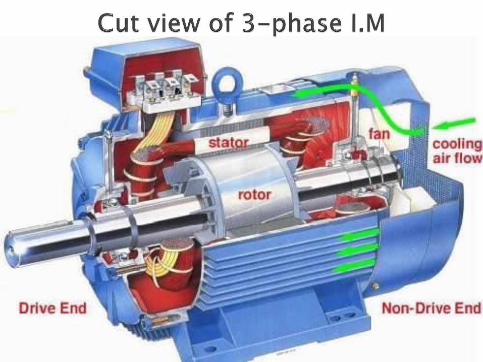
Cooling Fan
Bearings
Frame:
Frame provides mechanical support to the stator and rotor. It is made from casting materials.
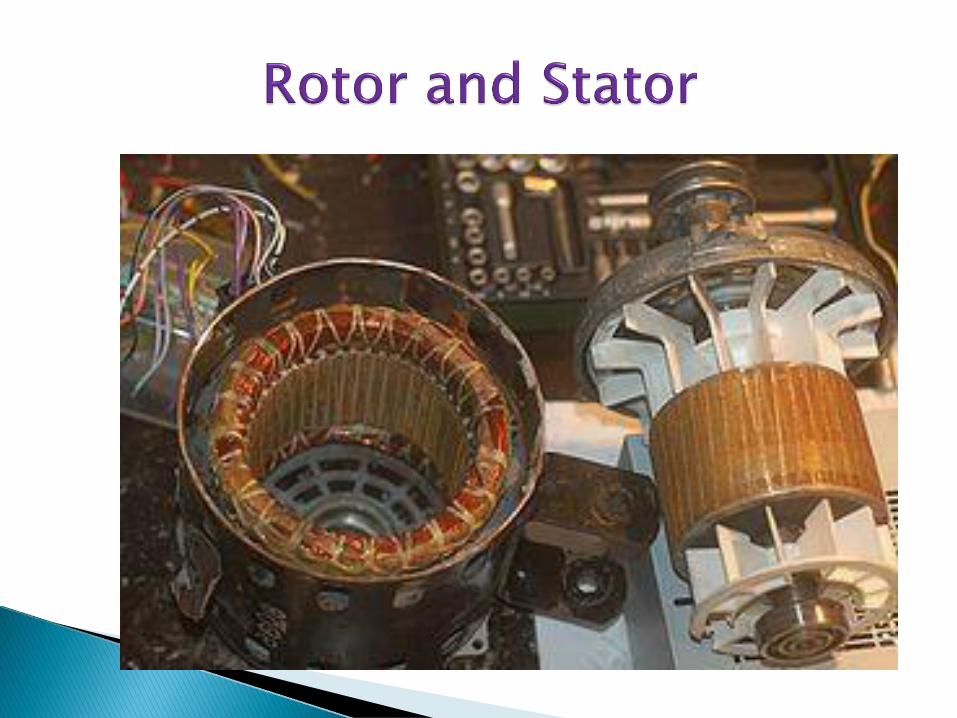
Stator:
It is stationary part of induction motor. It consists stator winding
It is housed on the motor frame.
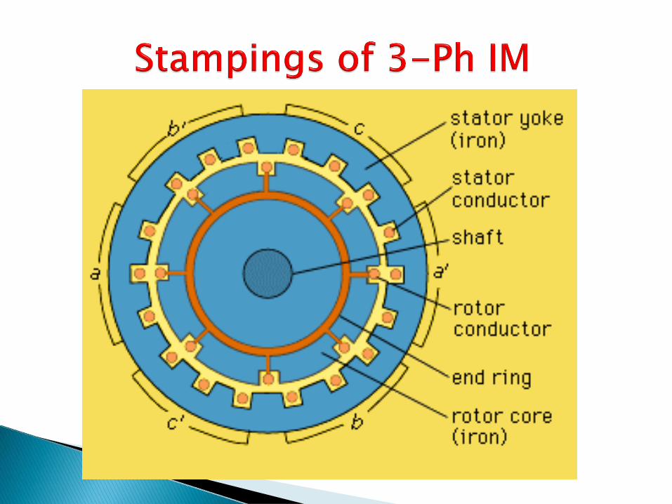
Arrangement of stator in 3-Ph induction motor are given below:-

Image of Rotor & Stator Winding of 3 phase Induction Motor

Components of 3-ph Induction Motor
Rotor:-
It is the rotating part of the induction motor.
It is housed on the shaft of the induction motor.
It has two ends, one is called Driving end and another is called non-
Driving end.
Mechanical load is connected on driving end while cooling fan is connected on non-driving end.
Both the ends are connected with bearings for free rotation means of reduced friction losses.
Arrangement of rotor of induction motor are given below:


Stator Windings:
Star connected
Delta connected
Rotor Windings:
It is wound as rotor bars and short circuited at both the ends through end rings.


According to rotor construction it can be Classified in two category according to rotor Construction:-
1. Squirrel cage induction motor
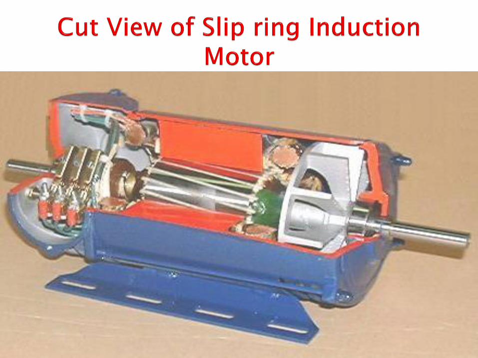
2. Slip ring induction motor


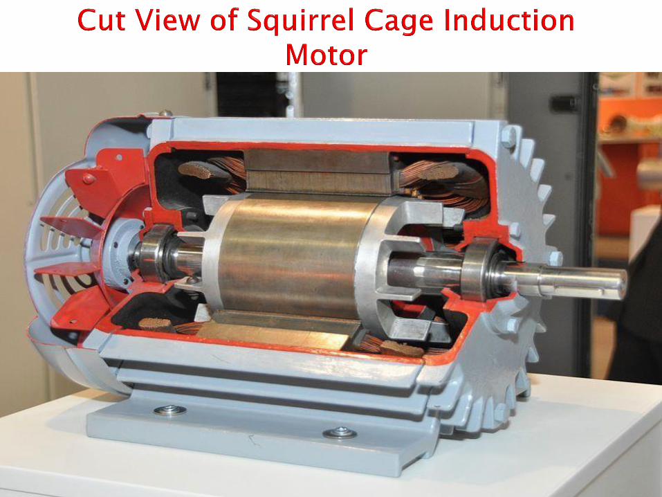

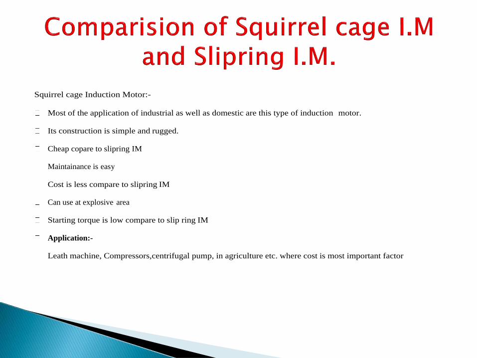
Squirrel cage Induction Motor:-
Most of the application of industrial as well as domestic are this type of induction motor.
Its construction is simple and rugged.
Cheap copare to slipring IM
Maintainance is easy
Cost is less compare to slipring IM
Can use at explosive area
Starting torque is low compare to slip ring IM
Application:-
Leath machine, Compressors,centrifugal pump, in agriculture etc. where cost is most important factor
Slipring Induction Motor:-
It has high starting torque compare to squirrel cage IM
Construction is complicated
Maintanance cost is high compare to squirrel cage IM
Starter requires compulsory
Can not use at explosive area
Application:-
Crane,hoist,lift and wherehigh starting torque is required


![Subject Name: ELECTROMECHANICAL ENERGY CONVERSION-I …電動機械... · 2015. 8. 4. · torque in machines with cylindrical air gap . Unit – 2 D.C. Machines: [14-22] Construction](https://static.fdocuments.in/doc/165x107/6135d3b30ad5d2067647a002/subject-name-electromechanical-energy-conversion-i-e-2015-8-4.jpg)