Electrical License Examination Guide · The examination question format, degree of difficulty, and...
33
m ~ DEPARTMENT OF 11 LABOR AND INDUSTRY Electrical License Examination Guide The information in this guide is provided by the Licensing Unit of the Department of Labor and Industry to ensure that applicants for personal electrician licenses administered by the department understand basic qualifications, knowledge areas, and examination criteria and format to enable them to successfully complete requirements to become licensed. Although this document contains a significant amount of detail, it should not be construed by applicants to be inclusive of all information necessary to successfully make application, pass a license examination, and subsequently become licensed by the department. It is the applicant’s responsibility to adequately prepare to successfully complete the license examination process. The examination question format, degree of difficulty, and length of examination has been in effect since July 1,2017. The 2017 National Electrical Code® became effective July 1, 2017 is the code edition used for the questions in the electrical license exams. The Lineman license examination is based on the 2017 National Electrical Safety Code®. 2018 LicensingExaminationGuide Checked 20190102 1
Transcript of Electrical License Examination Guide · The examination question format, degree of difficulty, and...

m~ DEPARTMENT OF 11 LABOR AND INDUSTRY
Electrical License Examination Guide The information in this guide is provided by the Licensing Unit of the Department of Labor and Industry to ensure that applicants for personal electrician licenses administered by the department understand basic qualifications, knowledge areas, and examination criteria and format to enable them to successfully complete requirements to become licensed. Although this document contains a significant amount of detail, it should not be construed by applicants to be inclusive of all information necessary to successfully make application, pass a license examination, and subsequently become licensed by the department. It is the applicant’s responsibility to adequately prepare to successfully complete the license examination process.
The examination question format, degree of difficulty, and length of examination has been in effect since July 1,2017.
The 2017 National Electrical Code® became effective July 1, 2017 is the code edition used for the questions in the electrical license exams.
The Lineman license examination is based on the 2017 National Electrical Safety Code®.
2018 LicensingExaminationGuide Checked 20190102 1

Table of Contents License Examination: Page 3
Purpose Page 3 General Page 3 Question Format Page 4 Degree of Difficulty Page 4 Length of Examination Page 5 Examination Results Page 5 Examination Reviewor Appeal Page 5
Sample Questions: Page 6
Formulas and Sample Calculations: Page 7
Examination Knowledge Areas: Page 19
American’s With Disabilities Act: Page 28
SchedulingExaminations: Page 30
Qualifications forLicense Applicants: Page 31 Electrical Engineering Degree Page 31 Technical College Program Credit Page 31 Military Experience Page 31 Practical Experience Acceptableto the Department Page 31 Experience Requirements byLicense Type Page 31 Qualification for Satellite System Installer Applicants Page 31
Reciprocal Licenses: Page 32
Continuing EducationRequirement Overview: Page 33
Personal License andExamination Application: Page 33
2018 LicensingExaminationGuide Checked 20190102 2
License Examination Purpose
Successfully completing a license examination provides evidence that the applicant possesses the necessary knowledge and expertise to be licensed in a specific profession or for a specific scope of work within a profession.
Licensing examinations are designed to assess the applicant’s competence after they have completed their qualifying education, training, and experience. Licensing examinations are designed to assess higher level skills than academic examinations by assessing the applicant’s ability to apply the competencies they gained from their education, training, and experience in actual practice.
Licensing examinations are intended to assure the public that the person passing an examination is qualified to practice within the scope of the license without causing harm to the public.
The purpose of this license examination guide is to provide applicants with awareness of knowledge areas covered by specific license examinations, question and examination format, degree of difficulty for specific license examinations, length of examination, and length of time allowed to complete their examination.
Applicants are encouraged to review this entire guide to ensure their understanding of the examination process and governing rules.
General
A copy of the National Electrical Code or the National Electrical Safety Code book is provided in the soft-cover format and do not include tabs or other aids. The edition of the National Electrical Code is the edition adopted as part of the state building code at the time the examination is administered. The edition of the National Electrical Safety Code is the most current edition at the time the examination is administered. The electronic calculator is of the common desk type that includes addition, subtraction, multiplication, division, square root, and percentage functions. The Laws and Rules Booklet provided for the examination is in the Department’s current format and represents the laws and rules in effect at the time the examination is administered.
1. Examination instructions are intended to be clear, concise, and complete. No questions may be asked of theexamination proctor (test administrator).
2. Examination questions and answer selections have been developed to be clear, concise, and complete.Applicants should understand the question without having to read the answer selections. No questions maybe asked of the examination proctor (test administrator).
3. Examination questions relate to knowledge areas within the scope of the applicable license.4. Examination questions reasonably cover the knowledge areas within the scope of the applicable license.5. Examination questions relate to knowledge areas that are common. The examination knowledge areas are
within the areas of work generally experienced by applicants for, or persons holding, the class of theapplicablelicense.
6. Applicants are allowed to use the National Electrical Code or National Electrical Safety Code (used only forthe lineman examination), a Laws and Rules Booklet, and an electronic calculator during their entireexamination. Unless code references are specifically required by an individual question, no code referencesare required as part of any answer. All reference materials and a calculator are provided by the Department.No other materials or electronic devices, including cell phones are allowed in the building. Althoughreference materials are available for the entire examination, applicants should be adequately prepared andnot rely on provided reference materials to answer all questions. The majority of questions are intended tobe answered without the applicant needing to refer to reference materials.
2018 LicensingExaminationGuide Checked 20190102 3
7. Applicants observed giving or receiving assistance from other applicants or outside parties shall beautomatically failed and required to submit a new application, including submission of required fees.
8. Applicants observed copying questions or making notes regarding questions shall be automatically failed andrequired to submit a new application, including submission of required fees.
9. During their examination, applicants may leave the examination room to use the restroom, but are notpermitted to leave the building. Applicants leaving the building prior to completing their examination shall beautomatically failed and required to submit a new application, including submission of required fees.
10. In addition to being monitored by the on-site proctor, the examination room may be electronically monitored.
11. Examination materials, including completed examinations and scoring keys are classified as nonpublic byMinnesota Statutes section 13.34. Applicants will only be provided with access to examination materialsduring the time they are being examined.
Question Format
1. Examination questions are formatted in a manner that requires the applicant to demonstrate mastery of theknowledgearea.
2. Variables in a question ensure that the appropriate knowledge area(s) or code rule(s) must be applied toarrive at the correctanswer.
3. Multiple-choice answer selections for knowledge areas with multiple conditions or requirements are wordedin a manner that requires the applicant to demonstrate knowledge of the subject matter and minimize theapplicant’s opportunity to select a correct answer(s) based on key words.
4. Questions with a negative-response format such as “which of the following does not apply,” are only used inlimited instances. This is a companion format to the multiple-correct answer format identified in 3 above.
5. Incorrect multiple-choice answer selections are “plausible.”
6. Questions may include extraneous information.
7. Unless stated otherwise in specific questions, all questions and related answers assume a “unity” powerfactor.
8. As many as 5 variations of an examination may be administered on the same examination date.
9. Individual examinations are modified not less than three times each National Electrical Code or NationalElectrical Safety Code cycle.
10. Examination questions and suggestions are accepted on an on-going basis from interested parties and become part of an examination question database from which examinations are created.
11. Some questions relate to code violations repeatedly made by installers of electrical wiring. Practicalexperience must be augmented by quality training to ensure the applicant’s complete and accurateunderstanding of electrical code and theory.
Degree of Difficulty
1. Each examination question is assigned a degree of difficulty rating from 1 to 5, with 5 being the mostdifficult. “Degree of difficulty” as used in administration of the department’s license examinations hasno relationship to academic “grade point average” achievement.
2. Questions rated least difficult (lowest) are those that relate to a single knowledge area, such asdefinitions or those requiring the application of a single code rule, or do not require complexmathematical calculations.
3. Questions rated most difficult (highest) are those that require the application of multiple code rules or
2018 LicensingExaminationGuide Checked 20190102 4
require multiple or complex mathematicalcalculations.
4. Each examination is assigned a degree of difficulty range that is commensurate with the responsibilityor authority of the applicablelicense.
5. Approximately 50% of specific license examination questions have a degree of difficulty within theoverall “degree of difficulty” range for the license type.
6. The examination for those license types that allow the holder of the license to be the “responsiblelicensed person” for an employer or contractor have an average degree of difficulty range between 2.5to 3.5. This category includes Class A master electrician, master elevator constructor, maintenanceelectrician, satellite system installer and power limited technician.
7. The examination for those license types that require the license holder to be provided with generalsupervision by a person holding a license type identified in 6 above have an average degree of difficultyrange between 1.5 to 2.5. These license types include Class A journeyworker and elevator constructor.
8. The examinations for Class B installer and lineman have an average degree of difficulty range between1.5 to 2.5.
9. Examination questions are structured to use words and phrases appropriate to the license, withoutusing non-electrical code and theory terms that would unnecessarily increase the degree of difficulty.
Length of Examination
1. The license examinations for the Class A master electrician and the Class A journeyworker electrician consists of 80 questions.
2. The license examination for the power limited technician consists of 80 questions.
3. The license examinations for the maintenance electrician consists of 70 questions, and lineman consist of 50 questions.
4. The license examination for the Class B and satellite system installer licenses consist of 25 questions.
5. Unless stated otherwise, all examination questions have the same point value. Partial points are not given - either full point credit or zero point credit is awarded for each question.
6. The passing score for all examinationsis 70 percent.
7. The time allowed to complete all examinations is 5½ hours.
Examination Results
1. Examination results are e-mailed and mailed to applicants generally within two weeks of the examination. Examination results are not provided to applicants by telephone.
2. Examination result letters mailed to applicants who passed their examinations will contain directions on how to obtain their license.
3. Examination result letters mailed to applicants who failed their examinations will contain directions on how to make subsequent application.
Examination Review or Appeal
1. Examinations with scores within five (5) percentage points of passing are rechecked to ensure accuracy.
2. Written or oral reviews of individual examinations are not available to applicants. Applicants mayprovide written comment to the Department’s licensing unit on specific examination questions.
3. Applicants who fail any examination may submit an application to retake the examination 30 days afternotification that they failed their examination.
2018 LicensingExaminationGuide Checked 20190102 5

Sample Questions The sample questions are intended to identify the various question formats that are used in the examinations. The knowledge areas used in the sample questions may not be applicable to all classes of examination.
1) Which one of the following conditions apply where Type NM cables are permitted to enter apanelboard through a nonflexible raceway without the cables being secured to the panelboard?
A The raceway extends directly above the enclosure without penetrating the structural ceiling.
B Because the cables are not secured to the enclosure with a fitting, they shall be strapped within 24-inches, measured along the cable sheath, of the outer end of the raceway.
C The raceway shall be at least 18-inches, but not more than 130-inches long. D The number of cables installed in the raceway is not limited where the raceway length is
not more than 24-inches.
Answer: A NEC 312.5(C) This question demonstrates a “single correct answer” multiple-choice question format.
2) Which of the four statements listed below does not correctly state code requirements pertainingto the installation of receptacle outlets installed to serve counter top surfaces in the kitchen of adwelling unit located in a multifamily dwelling?
A A receptacle outlet shall be installed at each wall counter space that is 12-inches or wider.
B The required receptacle outlets shall be supplied by not less than two small-appliance branch circuits.
C If located above, the receptacle outlets shall not be located more than 20-inches above the counter top.
D Only receptacle outlets installed within 6-inches of the outside edge of the sink(s) shall be required to be provided with ground-fault circuit-interrupter protection forpersonnel.
Answer: D NEC 210.52 This question demonstrates a “negative-response” multiple-choice question format.
3) A feeder supplies three 460-volt, three-phase, 1740 RPM, Design B, alternating-current motors.The motors have the following nameplate ratings: 25 horsepower, 28.4 amperes; 15 horsepower,18.2 amperes; and 10 horsepower, 11.3 amperes. Assuming all the motors are operating undercontinuous duty, what minimum size XHHW-2 copper feeder circuit conductors are required tosupply the motor load? The conductor terminations are rated at 75°C.
A 2 AWG B 3 AWG C 4 AWG D 6 AWG
Answer: 4 AWG NEC 430.6, 430.24, 430.250, 310.16 This question demonstrates an “absolute” multiple-choice question format.
2018 LicensingExaminationGuide Checked 20190102 6

4) When a single equipment grounding conductor is run with multiple branch circuits in the sameraceway or cable, how shall it be sized?
A The equipment grounding conductor shall be sized for the average rating of all the overcurrent devices protecting the conductors in the raceway or cable.
B The equipment grounding conductor shall be sized for the sum of all the overcurrent devices protecting the conductors in the raceway or cable.
C The equipment grounding conductor shall not be smaller than 10 AWG. D The equipment grounding conductor shall be sized for the largest overcurrent device
protecting the conductors in the raceway or cable.
Answer: D NEC 250.122(C) This question demonstrates a “common” multiple-choice question format.
Formulas and Sample Calculations The following information includes brief explanation and example of basic electrical formulas and calculations and is not intended to be inclusive of all formulas and calculations applicants need to be familiar with to successfully perform electrical work or receive a passing score on any license examination administered by the Department. Examples of more complex code calculations can be found in Annex D of the National Electrical Code as well as in other resources. Knowledge gained through practical experience is generally not adequate to enable an applicant to pass an electrical licensing examination. It is the responsibility of an applicant to adequately prepare themselves, either through formal training or informal, self-help training.
Units of Measurement:
The measurement system of preference for the National Electrical Code (Code) is now metric units in accordance with the modernized metric system known as the International System of Units (SI). The SI units appear first, followed by the inch-pound units in parentheses. This same system also applies to the Tables in Chapter 9 and the Annexes.
Compliance with the numbers shown in either the SI system or the inch-pound system constitutes compliance with the Code. Because most applicants are more familiar with the inch-pound units, all questions and answers in department license examinations use the inch-pound unit system. Answers for “absolute answer” format questions may be provided in either SI units or in inch-pound units.
Percentages, Ratios and Equations:
Electrical codes often give exact specifications based on exact criteria, then require that these specifications be adjusted if the circumstances differ from the criteria which the exact specifications were based on. In many cases, the original specified value is to be adjusted by a percentage. An example would be the ampacity adjustment factors for conductors. In other cases, the Code gives the applicable percentage to be used in design calculations. Examples of this would be applying demand factors, adjusting for continuous load or selecting overcurrent protection for motors or transformers. A percentage is defined as a ratio of a whole number to 100. The number value, including any decimal of this ratio, is multiplied by 100 and assigned the % sign.
2018 LicensingExaminationGuide Checked 20190102 7

Sample Percentage Questions:
1) What is 70% of 140?
• The percentage amount is divided by 100 to obtain the decimal equivalent: (70 ÷ 100 = .70)• 140 is multiplied by .70 (140 x .70 = 98)• Answer: 70% of 140 = 98
2) What is the result of increasing 120 by 25%?
• The percentage amount is divided by 100 (25 ÷ 100 = .25)• 120 is multiplied by .25 (120 x .25 = 30)• 30 is then added to the original value of 120 (30 + 120 = 150)• Answer: 120 x 1.25 = 150
Sample Ratio Question:
A ratio is defined as a fixed comparison or proportion between two similar values, such as primary vs. secondary or input vs. output.
1) A single-phase transformer has a nameplate voltage rating of 480/120. What is the ratio of theprimary voltage to the secondary voltage?
• The primary voltage is divided by the secondary voltage (480 ÷ 120 = 4)• Answer: The ratio of the primary voltage to the secondary voltage is 4:1
How to transpose equations:
Formulas used in code and theory calculations are in the form of equations. An equation is a statement of equality of two quantities of variables, such as A x B = C. While it is important to remember the definition of an equation, it is more important to know how to transpose an equation that is not expressed as being equal to the variable that is unknown. As an example, Ohm’s law and Watt’s law contain three variables that can be transposed into 10 other equations. Equations (formulas) can be transposed by one or more of the following operations performed equally on each side of the equal sign (=): addition, subtraction, multiplication or division.
Two things to remember: • A variable divided by itself equals 1; and• Multiplying a variable by 1 does not change the variable and is not shown in the final equation
1) If A x B = C. Solve for A.
• To transpose this formula we divide both sides of the equation by B (A x B) ÷ B = C ÷ B• B ÷ B = 1• A x 1 = C ÷ B• Answer: A = C ÷ B
2018 LicensingExaminationGuide Checked 20190102 8

Ohm’s Law (E = I x R):
Ohm’s law expresses the relationship of three variables, E, I and R. The electromotive force in volts is represented by the letter E, the current in amperes is represented by the letter I, and the resistance in ohms is represented by the letter R.
In certain alternating current circuits, the term impedance is used rather than resistance. Impedance is a combination of resistance and reactance and is represented by the letter Z.
1) In a series circuit, the voltage dropped across a 30 Ω resistor is 75-volts. What is the current of thecircuit?
• If E = I x R, then I = E÷ R• I = 75 ÷ 30• Answer: I = 2.5 amperes
Watt’s Law (P = E x I)
Watt’s law expresses the relationship of three variables, P, E, and I. The power of an electrical circuit in watts is represented by the letter P, the electromotive force in volts is represented by the letter E, and the current in amperes is represented by the letter I. Watts is the term for the true power being used in an electrical circuit. True power is only produced when the voltage and current sine waves are both either positive or negative, referred to as a unity power factor. The product of E x I must be a positive number for watts to be produced. A positive number times a negative number results in a negative number. As an example: (pos x pos = pos), neg x neg = pos), (neg x pos = neg)
1) An electric baseboard heater is rated 1500 watts at 240-volts. What is the current drawn by theheater?
• If P = E X I, then I = P ÷ E• I = 1500 ÷ 240• Answer: I = 6.25 amperes
Resistance in Series and Parallel Circuits
For the purposes of this discussion of resistance, direct current circuits and alternating circuits that do not contain inductive or capacitive loads (unity power factor) are used.
In a series circuit, the current is the same at any point in the circuit, the total resistance is the sum of the individual resistors, and the applied voltage is equal to the sum of the voltage dropped across all the resistors.
1) A series circuit, consists of three resistors valued at 20 Ω, 40 Ω, and 60 Ω respectively. If the currentof the circuit is 2 amperes, what is the source voltage?
• If E = I x R• R total = R1 + R2 + R3• R total = 20 + 40 + 60 then R total = 120 Ω• E = 2 x 120• Answer: E = 240 volts
2018 LicensingExaminationGuide Checked 20190102 9

= Amps V = Volts
R P = Watts R = Ohms
A parallel circuit is a circuit with more than one path for current flow. The total flow in the circuit is equal to the sum of the currents in all the branches. The voltage drop across any branch of the parallel circuit is equal to the voltage applied to the parallel branch.
There are three methods of determining the total resistance in a parallel circuit.
1) When resistors of equal value are connected in parallel, the total resistance is equal to the value ofthe resistance of the resistor divided by the number of resistors.
1) What is the total resistance of three 15 Ω resistors connected in parallel?
• R total = R ÷ N• R total = 15 ÷ 3• Answer: RT = 5Ω
2) The product over sum method can be used for two different resistance values. In a circuit with morethan two resistors or branches, the product over sum method can be used sequentially until onlyone pair of resistors is left. For example: RT = (R1 x R2) ÷ (R1 + R2)
What is the total resistance of a 20 Ω and a 30 Ω resistor connected in parallel?
• RT = (R1 x R2) ÷ (R1 + R2)• RT = (20 x 30) ÷ (20 + 30)• RT = 600 ÷ 50• Answer: RT = 12 Ω
3) The third method is the reciprocal method. The total resistance of a parallel circuit is equal to thereciprocal of the sum of the reciprocals of the resistor values.
1 = 1 + 1 + 1RT R1 R2 R3
What is the total resistance of a 2 Ω, 4 Ω and 8 Ω resistor connected in parallel?
1 = 1 + 1 + 1 RT 2 4 8
1 = .5 + .25 + .125RT
1 = .875 RT
RT = 1 .875
Answer: RT = 1.143 Ω
2018 LicensingExaminationGuide Checked 20190102 10
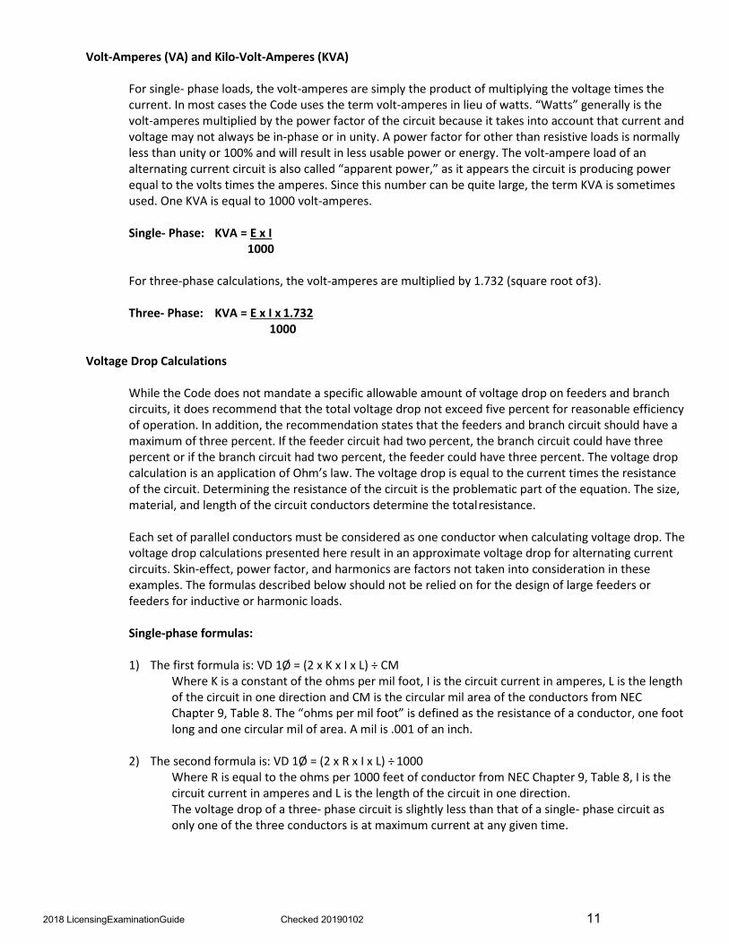
Volt-Amperes (VA) and Kilo-Volt-Amperes (KVA)
For single- phase loads, the volt-amperes are simply the product of multiplying the voltage times the current. In most cases the Code uses the term volt-amperes in lieu of watts. “Watts” generally is the volt-amperes multiplied by the power factor of the circuit because it takes into account that current and voltage may not always be in-phase or in unity. A power factor for other than resistive loads is normally less than unity or 100% and will result in less usable power or energy. The volt-ampere load of an alternating current circuit is also called “apparent power,” as it appears the circuit is producing power equal to the volts times the amperes. Since this number can be quite large, the term KVA is sometimes used. One KVA is equal to 1000 volt-amperes.
Single- Phase: KVA = E x I 1000
For three-phase calculations, the volt-amperes are multiplied by 1.732 (square root of3).
Three- Phase: KVA = E x I x 1.732 1000
Voltage Drop Calculations
While the Code does not mandate a specific allowable amount of voltage drop on feeders and branch circuits, it does recommend that the total voltage drop not exceed five percent for reasonable efficiency of operation. In addition, the recommendation states that the feeders and branch circuit should have a maximum of three percent. If the feeder circuit had two percent, the branch circuit could have three percent or if the branch circuit had two percent, the feeder could have three percent. The voltage drop calculation is an application of Ohm’s law. The voltage drop is equal to the current times the resistance of the circuit. Determining the resistance of the circuit is the problematic part of the equation. The size, material, and length of the circuit conductors determine the totalresistance.
Each set of parallel conductors must be considered as one conductor when calculating voltage drop. The voltage drop calculations presented here result in an approximate voltage drop for alternating current circuits. Skin-effect, power factor, and harmonics are factors not taken into consideration in these examples. The formulas described below should not be relied on for the design of large feeders or feeders for inductive or harmonic loads.
Single-phase formulas:
1) The first formula is: VD 1Ø = (2 x K x I x L) ÷ CMWhere K is a constant of the ohms per mil foot, I is the circuit current in amperes, L is the length of the circuit in one direction and CM is the circular mil area of the conductors from NEC Chapter 9, Table 8. The “ohms per mil foot” is defined as the resistance of a conductor, one foot long and one circular mil of area. A mil is .001 of an inch.
2) The second formula is: VD 1Ø = (2 x R x I x L) ÷ 1000Where R is equal to the ohms per 1000 feet of conductor from NEC Chapter 9, Table 8, I is the circuit current in amperes and L is the length of the circuit in one direction. The voltage drop of a three- phase circuit is slightly less than that of a single- phase circuit as only one of the three conductors is at maximum current at any given time.
2018 LicensingExaminationGuide Checked 20190102 11

Three-phase formulas:
If you are using either VD 1Ø = (2 x K x I x L) ÷ CM or VD 1Ø = (2 x R x I x L) ÷ 1000, these formulas are modified as follows for three-phase applications:
• VD 3Ø = (1.732 x K x I x L) ÷ CM
• VD 3Ø = (1.732 x R x I x L) ÷ 1000
1) What is the voltage drop on a 240-volt, single-phase circuit, that is 150 feet from thepanelboard, has a current of 28 amperes and No.8 THWN copper conductors?
• Use K = 12.8• VD 1Ø = (2 x K x I x L) ÷ CM• VD 1Ø = (2 x 12.8 x 28 x 150) ÷16510• VD 1Ø = 107520 ÷ 16510• Answer: VD 1Ø = 6.5–volts
2) What is the voltage drop on a 208-volt, three-phase branch circuit, that is 205 feet from thepanelboard, has a current of 33 amperes, and the conductors have a resistance of .510 Ωper 1000 feet?
• VD 3Ø = (1.732 x R x I x L) ÷ 1000• VD 3Ø = (1.732 x .510 x 33 x 205) ÷1000• VD 3Ø = 5976 ÷ 1000• Answer: VD 3Ø = 5.98volts
Percentage of Voltage Drop
1) What is the percentage of voltage drop on a 480 volt, three-phase, feeder circuit, that is 280 feetfrom the service equipment to the panelboard, has a current of 135 amperes, and 250 kcmil XHHW-2 aluminum conductors?
• Use K = 21.1• VD 3Ø = (1.732 x K x I x L) ÷ CM• VD 3Ø = (1.732 x 21.1 x 135 x 280) ÷ 250,000• VD 3Ø = (1,381,409 ÷ 250,000)• VD 3Ø = 5.53 volts• Percent of VD = VD ÷ EL-L x 100• Percent of VD = 5.53 ÷ 480 x 100• Percent of VD = .01152 x 100• Answer: Percent of VD =1.15%
Transformer Ratings
Transformers are commonly rated in KVA. The term KVA is a measure of apparent power in units of 1000 volt-amperes. The term KVA is not to be confused with KW (kilo-watts). KW is a measure of true power units of 1000 watts. Even though there are some losses associated with transformers, for general calculations the KVA of the primary is considered equal to the KVA of the secondary. The nameplate of the transformer generally includes the KVA rating, primary and secondary voltages or combinations, the manufacturer’s name, temperature rise, percent of impedance and if it is single- or three-phase.
Single-Phase KVA = E x I Three-Phase KVA = E x I x 1.732 1000 1000
2018 LicensingExaminationGuide Checked 20190102 12

1) Single-Phase Example: A 25 KVA, single-phase transformer is rated 480-120/240 volts. What is thefull load, primary current rating?
• 1Ø KVA = (E x I) ÷1000• I = (KVA x 1000) ÷ E• I = (25 X 1000) ÷ 480• I = 25000 ÷ 480• Answer: I = 52 amperes
2) Three-Phase Example: For three-phase loads the KVA rating is equal the voltage times the currenttimes 1.732. A three-phase, 750 KVA transformer is rated at 4160-208/120 volts. What is the fullload, secondary current rating?
• 3Ø KVA = E x I X 1.732 ÷ 1000• I = (KVA x 1000) ÷ (E x 1.732)• I = (750 x 1000) ÷ (208 x 1.732)• I = 750000 ÷ 360.26• Answer: I = 2081 amperes
Transformer Short-Circuit Fault Current Calculations
The available short-circuit fault current value must be known to properly select equipment ratings. Although there are a number of factors that will affect the available short-circuit fault current at any point on an electrical system, most calculations begin with determining the maximum available short-circuit fault current at the load terminals of a transformer under a bolted short circuit condition without any short-circuit or overcurrent protection and assuming an infinite primary source. Only transformer short-circuit fault current calculations are demonstrated by the following examples. The formula for maximum available fault current for a transformer is:
Short-circuit current [SC] = transformer secondary full-load amperes [FLA] x the multiplier
The transformer multiplier is equal to 100 divided by the transformer impedance expressed as a percentage. The transformer impedance is generally marked on the nameplate of the transformer and is identified by the letter “Z”.
1) What is the maximum available short-circuit fault current for a transformer with the followingsecondary nameplate rating: 75 kva, 120/240 volt, single- phase, 2.5% Z?
The transformer full-load ampere rating is 75000 ÷ 240 = 312.5 The multiplier is 100 ÷ 2.5% = 40 The maximum available short-circuit fault current: 312.5 (transformer full-load amperes) x 40 (multiplier) = 12,500 short-circuit fault current Answer: 12,500 amperes
2) What is the maximum available short-circuit fault current for a transformer with the followingsecondary nameplate rating: 45 kva, 120/208 volt, three- phase wye, 1.2% Z?
The transformer full-load ampere rating is 45000 ÷ (208 x 1.732) = 125 The multiplier is 100 ÷ 1.2 = 83.33 The maximum available short-circuit fault current: 125 (transformer full-load amperes) x 83.33 (multiplier) = 10416 (short-circuit fault current) Answer: 10416 amperes
2018 LicensingExaminationGuide Checked 20190102 13

3) What is the maximum available short-circuit fault current for a transformer with the followingnameplate rating: 750 kva, 277/480 volt, three-phase wye, 2.75% Z?
The transformer full-load ampere rating is 750,000 ÷ (480 x 1.732) = 902 The multiplier is 100 ÷ 2.75 = 36.36 The maximum available short-circuit fault current: 902 (transformer full-load amperes) x 36.36 (multiplier) = 32,797 (short-circuit fault current) Answer: 32,797 amperes
The examples illustrated above are for line-to-line faults. Line-to-neutral or line-to-ground faults will generally result in 10 to 15% higher available short-circuit fault currents.
Not considering any reduction based on circuit impedance or increase from motor load contribution, the equipment connected to the load side of the transformers in the illustrations above must have a short-circuit or interrupt rating not less than the calculated available short-circuit fault current for each question.
Additional information regarding short-circuit fault current calculations is available through many sources, including manufacturers of overcurrent devices.
Conduit Fill Calculations
Annex C of the National Electrical Code contains the Tables for conduit and tubing fill for conductors and fixture wires of the same size. Every type of conduit, flexible conduit or tubing in which conductors are field installed has two tables listing the maximum number of any given wire size (gauge) and type (insulation). These Tables apply to raceways longer than 24-inches.
1) How many No.10 AWG, Type THWN conductors may be installed in trade size 1½, Schedule 80,Polyvinyl Chloride Conduit?
• The answer is found using NEC Table C9• Find the portion of the table that applies to Type THWN conductors• Find No.10 AWG in the conductor size column and read the number of conductors for
the appropriate, trade size raceway from the table• If you choose to calculate the number of conductors, rather than use the tables in Annex
C, you must apply the provisions of Note 8• Answer: 32 conductors
When a conduit or tubing contains several different size conductors or contains conductors with different types of insulation, a more complex procedure is to be followed. In general, this procedure involves three steps. First, determine the combined square inch area of all the conductors. Second, determine the percent of cross sectional area allowed for conductors based on the number of conductors to be installed in the conduit. Third, select the size conduit or tubing that has a “percent of area” determined in step one that exceeds the square inch area required for the conductors determined in step two. This information is found in the tables in NEC Chapter 9. Where conduit or tubing nipples not longer than 24-inches are installed between boxes, cabinets or similar enclosures, the nipples shall be permitted to be filled to 60 percent of their total cross sectional area.
2018 LicensingExaminationGuide Checked 20190102 14

2) What is the minimum trade size Rigid Metal Conduit required for six - No.3 AWG THW; six – No.6AWG THWN; one – No.8 AWG THWN; and twelve - No.14 AWG XHHW conductors?
• Using NEC Chapter 9, Table 1 it is determined that 40% of the cross sectional area of the rigidmetal conduit may be used for conductor fill because it will contain over 2 conductors.
• From NEC Chapter 9, Table 5, determine the square inch area of all the conductors, based ontheir size and insulation type.
o No.3 THW - 0.1134 sq. in. times 6 conductors = 0.6804 sq. in.o No.6 THWN - 0.0507 sq. in. times 6 conductors = 0.3042 sq. in.o No.8 THWN - 0.0366 sq. in. times 1 conductor = 0.0366 sq. in.o No.14 XHHW - 0.0139 sq. in. times 12 conductors = 0.1668 sq. in.o The total cross-section area of the conductors is 1.1880 sq. in
• Using NEC Chapter 9, Table 4 under the heading of Rigid Metal Conduit, determine from the40% column, the minimum size conduit that exceeds 1.1880 square inches.
• Answer: trade size 2
Conductor Ampacity
NEC Table 310.15(B)(16) lists the allowable ampacities of conductors rated 0–2000 volts, 60°C through 90°C, based on an ambient temperature of 30°C and not more than three current-carrying conductors in a raceway, cable or directly buried in the earth. When conductors are used within these specific criteria it is simply a matter of selecting the ampacity from the table based on the conductor size, insulation type and material. These criteria limit the amount of heat generated by the current flowing through the conductor to a safe level. Conductors used outside of these criteria must have their ampacities adjusted accordingly.
There are two variables that may need to be considered: ambient temperatures and the numbers of conductors in a raceway.
Ambient Temperature:
On occasion, conductors are used in environments that are warmer than an ambient temperature of 30°C (86°F). The higher temperature environments limit a conductor’s ability to safely dissipate the heat generated by the conductor, so the ampacity must be reduced. NEC Table 310.15(B)(2)(a) includes correction factors for ambient temperatures other than 30°C (86°F). To correct the conductor ampacity based on ambient temperature, multiply the allowable ampacities by the appropriate factor of the ambient in which the conductor will operate. In addition, the temperature limitations equipment terminations described in NEC section 110.14 must be applied when conductor ampacity/overcurrent rating is determined.
1) What is the allowable ampacity of a No.1/0 THWN copper conductor when installed in an ambienttemperature of 107° F?
• NEC Table 310.15(B)(16)lists the allowable ampacity of No.1/0 THWN copper, a 75°C ratedconductor as 150 amperes
• The correction factor is .82• 150 x .82 = 123 amperes• Answer: 123 amperes
2018 LicensingExaminationGuide Checked 20190102 15

Number of Conductors in a Raceway
Often more than three current-carrying conductors are installed in a single raceway. Once again the allowable ampacity of the conductors must be reduced to prevent overheating and damage to conductor insulation.
NEC Table 310.15(B)(3)(a) specifies the percentage of adjustment required based on the number of current-carrying conductors in the raceway or cable.
The percentages given in NEC Table 310.15(B)(3)(a) are applied to the allowable ampacities of Tables 310.16 through 310.19 after any correction for ambient temperature has been made.
1) A trade size 1¼ conduit contains three, 3-phase motor circuits and an equipment groundingconductor. The motors run at the same time and the conductors are No.8 THHN copper. What is theallowable ampacity of these conductors?
• From NEC Table 310.15(B)(16), the allowable ampacity of a No.8 THHN copper conductor is 55amperes.
• The 55 ampere rating is based on not more than three current-carrying conductors in theraceway and an ambient temperature of 30°C.
• Because a different ambient temperature is not stated, no correction for ambient temperatureis required, the percentages given in NEC Table 310.15(B)(3)(a) to the ampacity listed in thetable are applied
• In this case it is 70% based on the nine current-carrying conductors.• Note: NEC section 310.15(B)(6) provides that the equipment grounding conductor is not
counted when applying the provisions of section 310.15(B)(3)(a).• 55 x .70 = 38.5 Amperes• Answer: 38.5 Amperes
Box Fill Calculations
The Code requires that boxes and conduit bodies be of sufficient size to provide ample free space for conductors, connections and where applicable, wiring devices. These requirements are found in NEC section 314.16.
1) What is the maximum number of No.10 AWG THHN conductors that may be installed in a 4 x 2⅛square box?
This answer can be taken directly from NEC Table 314.16(A) as there are no other volume allowances required. Answer: 12 conductors
2) What is the maximum number of No.12 AWG conductors that may be installed in a box that ismarked with a volume of 60 cubic inches?
• NEC Table 314.16(B) gives the volume allowance required per conductor• In this case, 2.25 cubic inches are required for each No.12 AWG conductor• Divide the volume of the box by the volume allowance of the conductor• Do not round up!• 60 cubic inches ÷ 2.25 cubic inches = N• N = 26.67• Answer: 26 conductors
2018 LicensingExaminationGuide Checked 20190102 16

Boxes that contain devices, cable clamps, support fittings, equipment grounding conductors or different size conductors shall be sized in accordance with NEC section 314.16(B), sections (1) – (5). These five sections prescribe the number of volume allowance(s) required for each item listed above.
3) A 2-gang, nonmetallic box is to be used for a 3-way switch and duplex receptacle outlet. Type NMcable is used as the wiring method. The box contains a 14-2 and a 14-3 cable for the lighting circuitand two, 12-2 cables for the outlet circuit. The box has internal cable clamps to secure the cables.What is the minimum cubic inch volume of the box?
Determine the volume required for the conductors. Do not count the equipment groundingconductors at this time.
• No.14 conductors: 5 x 2.0 cubic inches = 10 cubic inches.• No.12 conductors: 4 x 2.25 cubic inches = 9 cubic inches.
o Combine the volume required for the conductors: 10 cubic inches + 9 cubic inches = 19cubic inches.
• Since the box has cable clamps, a single volume allowance, based on the size of the largestconductor in the box shall be made.
o The volume allowance shall be in accordance with NEC Table 314.16(B).o The volume allowance for the clamps is 2.25 cubic inches, based on No.12 being the
largest conductor.• A double volume allowance shall be made for each strap or yoke containing one or more devices
or equipment, based on the size of the largest conductor connected to the device.o The volume allowance for the 3-way switch is 4 cubic inches (2 x 2 cubic inches) and the
volume allowance for the duplex receptacle is 4.5 cubic inches (2 x 2.25 cubic inches).o The volume allowances shall be in accordance with NEC Table 314.16(B).o The total of the volume allowances for the devices is 8.5 cubic inches (4 cubic inches +
4.5 cubic inches = 8.5 cubic inches).• Where one or more equipment grounding conductors enter a box, a single volume allowance
based on the largest equipment grounding conductor shall be made.o Note that even though the equipment grounding conductors are from different circuits,
a single volume allowance is made.o The volume allowance for the equipment grounding conductors is 2.25 cubic inches,
based on No.12 being the largest conductor.• Combine the volume allowance for the conductors, clamps, devices and the equipment
grounding conductors.• 19 cubic inches (conductors) + 2.25 cubic inches (clamps) + 8.5 cubic inches (devices) + 2.25
cubic inches (grounding conductors) = 32 cubic inches• Answer: 32 cubic inches
2018 LicensingExaminationGuide Checked 20190102 17
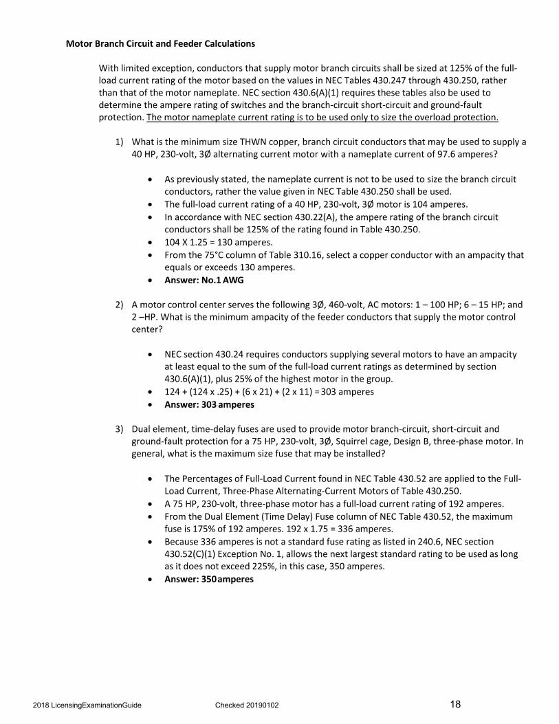
Motor Branch Circuit and Feeder Calculations
With limited exception, conductors that supply motor branch circuits shall be sized at 125% of the full-load current rating of the motor based on the values in NEC Tables 430.247 through 430.250, rather than that of the motor nameplate. NEC section 430.6(A)(1) requires these tables also be used to determine the ampere rating of switches and the branch-circuit short-circuit and ground-fault protection. The motor nameplate current rating is to be used only to size the overload protection.
1) What is the minimum size THWN copper, branch circuit conductors that may be used to supply a40 HP, 230-volt, 3Ø alternating current motor with a nameplate current of 97.6 amperes?
• As previously stated, the nameplate current is not to be used to size the branch circuitconductors, rather the value given in NEC Table 430.250 shall be used.
• The full-load current rating of a 40 HP, 230-volt, 3Ø motor is 104 amperes.• In accordance with NEC section 430.22(A), the ampere rating of the branch circuit
conductors shall be 125% of the rating found in Table 430.250.• 104 X 1.25 = 130 amperes.• From the 75°C column of Table 310.16, select a copper conductor with an ampacity that
equals or exceeds 130 amperes.• Answer: No.1 AWG
2) A motor control center serves the following 3Ø, 460-volt, AC motors: 1 – 100 HP; 6 – 15 HP; and2 –HP. What is the minimum ampacity of the feeder conductors that supply the motor controlcenter?
• NEC section 430.24 requires conductors supplying several motors to have an ampacityat least equal to the sum of the full-load current ratings as determined by section430.6(A)(1), plus 25% of the highest motor in the group.
• 124 + (124 x .25) + (6 x 21) + (2 x 11) = 303 amperes• Answer: 303 amperes
3) Dual element, time-delay fuses are used to provide motor branch-circuit, short-circuit andground-fault protection for a 75 HP, 230-volt, 3Ø, Squirrel cage, Design B, three-phase motor. Ingeneral, what is the maximum size fuse that may be installed?
• The Percentages of Full-Load Current found in NEC Table 430.52 are applied to the Full-Load Current, Three-Phase Alternating-Current Motors of Table 430.250.
• A 75 HP, 230-volt, three-phase motor has a full-load current rating of 192 amperes.• From the Dual Element (Time Delay) Fuse column of NEC Table 430.52, the maximum
fuse is 175% of 192 amperes. 192 x 1.75 = 336 amperes.• Because 336 amperes is not a standard fuse rating as listed in 240.6, NEC section
430.52(C)(1) Exception No. 1, allows the next largest standard rating to be used as longas it does not exceed 225%, in this case, 350 amperes.
• Answer: 350amperes
2018 LicensingExaminationGuide Checked 20190102 18
I I I I
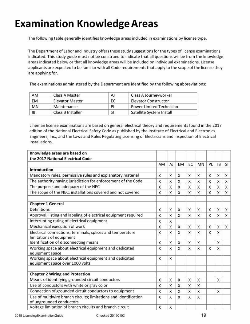
Examination Knowledge Areas The following table generally identifies knowledge areas included in examinations by license type.
The Department of Labor and Industry offers these study suggestions for the types of license examinations indicated. This study guide must not be construed to indicate that all questions will be from the knowledge areas indicated below or that all knowledge areas will be included on individual examinations. License applicants are expected to be familiar with all Code requirements that apply to the scope of the license they are applying for.
The examinations administered by the Department are identified by the following abbreviations:
AM Class A Master AJ Class A Journeyworker EM Elevator Master EC Elevator Constructor MN Maintenance PL Power Limited Technician IB Class B Installer SI Satellite System Install
Lineman license examinations are based on general electrical theory and requirements found in the 2017 edition of the National Electrical Safety Code as published by the Institute of Electrical and Electronics Engineers, Inc., and the Laws and Rules Regulating Licensing of Electricians and Inspection of Electrical Installations.
Knowledge areas are based on the 2017 National Electrical Code
AM AJ EM EC MN PL IB SI Introduction Mandatory rules, permissive rules and explanatory material X X X X X X X X The authority having jurisdiction for enforcement of the Code X X X X X X X X The purpose and adequacy of the NEC X X X X X X X X The scope of the NEC: installations covered and not covered X X X X X X X X
Chapter 1 General Definitions X X X X X X X X Approval, listing and labeling of electrical equipment required X X X X X X X X Interrupting rating of electrical equipment X X Mechanical execution of work X X X X X X X X Electrical connections, terminals, splices and temperature limitations of equipment
X X X X X X X
Identification of disconnecting means X X X X X X Working space about electrical equipment and dedicated equipment space
X X X X X X X
Working space about electrical equipment and dedicated equipment space over 1000 volts
X X
Chapter 2 Wiring and Protection Means of identifying grounded circuit conductors X X X X X X Use of conductors with white or gray color X X X X X Connection of grounded circuit conductors to equipment X X X X X X Use of multiwire branch circuits; limitations and identification of ungrounded conductors
X X X X X
Voltage limitation of branch circuits and branch circuit X X
2018 LicensingExaminationGuide Checked 20190102 19

receptacle requirements Ground-fault circuit-interrupter protection for personnel X X X X X Number and types of branch circuits required X X Arc-fault circuit-interrupter protection required X X X Branch circuit ratings; overcurrent protection and permissibleloads
X X
Required receptacle outlets for dwellings, guest rooms and equipment requiring service
X X
Required lighting outlets X X Minimum rating, size and overcurrent protection of feeders X X Means of identifying a conductor with a higher voltage toground
X X X X X X
Computation of branch circuit loads including lighting, receptacles and household appliances
X X
Maximum loads permitted to be supplied by branch circuits X X Computation of feeder and service loads for dwellings, non-dwellings and farms
X X
Computation of feeder and service neutral load X X Lighting equipment installed outdoors X X Branch circuit and feeder conductors installed overhead X X Number of supplies to additional structures X X Requirements for disconnecting means at additional structures; suitable for service equipment
X X
Number of services permitted to a building or structure X X Service conductors considered outside of a building X X Other conductors not permitted in service raceways or cables X X Clearances from building openings, above roofs and vertical clearance from ground
X X
Size and rating of service drop conductors; point and means of attachment
X X
Size and rating of service lateral conductors; protection against damage and spliced conductors
X X
Number of service-entrance conductor sets X X Minimum size and rating of service entrance conductors X X Requirements for overhead service locations; drip loops and arranged that water will not enter
X X
Service disconnecting means; readily accessible location and suitable for use
X X
Maximum number of service disconnects; grouping of disconnects and access to occupants
X X
Minimum rating of service disconnecting means and combined rating of disconnects
X X
Equipment permitted to be connected to the supply side of the service disconnect
X X
Overload protection for service conductors X X Ground-fault protection of equipment; settings and performance testing
X X X
Overcurrent protection of conductors; devices rated 800 amperes or less
X X
Overcurrent protection of conductors; devices rated over 800 amperes
X X
Overcurrent protection of small conductors, tap conductors, and transformer secondary conductors
X X X X
Standard ampere ratings of fuses and circuit breakers X X X X X Location of overcurrent protection in a circuit; branch circuit and feeder tap rules
X X
2018 LicensingExaminationGuide Checked 20190102 20

Conditions where overcurrent protection is allowed in series with the grounded circuit conductor
X X X X
Location of overcurrent devices; readily accessible, accessible to occupants
X X X
Locations where overcurrent devices are not permitted X X Maximum voltage and limitations of plug fuses X X X Marking of circuit breakers; interrupting rating; use as switches and voltage rating
X X X X X X
Application of straight voltage rating; slash voltage rating; and series ratings of circuit breakers
X X X X X X
Definitions of terms associated with grounding and bonding X X X X X X X X General requirements for grounding and bonding X X X X X X X X Grounding connections arranged to prevent objectionable current over the grounding system
X X X X X
Grounding and bonding connections required to be made by listed means
X X X X X X X X
Alternating-current circuits and systems required to be grounded or not required to be grounded
X X X
Grounding A-C Services: grounding electrode conductor connected to the grounded conductor
X X X
Grounding A-C Services: additional grounding connection made at outdoor transformers
X X X
Grounding A-C Services: main bonding jumper required; material, construction, attachment, and size
X X X
Grounding A-C Services: grounded conductor required to be brought to the service equipment, minimum size
X X X
Grounding A-C Systems: conductor required to be grounded X X X Grounding separately derived systems: bonding jumper and equipment bonding jumper size
X X X
Grounding separately derived systems: grounding electrode and grounding electrode conductor and taps
X X
Grounding A-C Services: two or more buildings or structures supplied from a common service
X X
Electrodes permitted for grounding; installing the grounding electrode system; supplemental electrode required
X X X
Requirements for installing the grounding electrode conductor; material; minimum size required; protection from physical damage
X X X
Connections to the grounding electrode X X X X X Methods of bonding at the service; provisions for bonding other systems required
X X X X X X
Bonding for circuits over 250 volts X X X X Bonding in hazardous (classified) locations X X X X Equipment bonding jumpers: size on supply side of the service; size on load side of the service
X X X
Bonding of piping systems and exposed structural steel X X X Equipment grounding and equipment grounding conductors X X X X X X X Types of equipment grounding conductors and means of identification of equipment grounding conductors
X X X X X X X
Size of equipment grounding conductors; multiple circuits, and conductors in parallel
X X X X X X X
Methods of equipment grounding X X X X X X X Use of the grounded circuit conductor for grounding equipment; supply-side equipment, load-side equipment
X X X X
Connection of the receptacle grounding terminal to the outlet box; continuity and attachment of equipment grounding conductors to boxes
X X X X X X X
2018 LicensingExaminationGuide Checked 20190102 21

Chapter 3 Wiring Methods and Materials All conductors of the same circuit contained in the same raceway, trench, cable, etc.
X X X X X X
Conductors of different systems permitted in the same enclosure or raceway
X X X X X X X
Conductors protected from physical damage, bored holes, notches in wood, through and parallel to framing members
X X X X
Insulating fittings required for conductors 4 AWG and larger X X X X X X Underground installations, minimum cover requirements forvarious wiring methods and locations
X X X X X
Underground installations, protection from damage, splices and taps, bushings required, all conductors of the same circuit, ground movement
X X X X
Sealing raceways exposed to different temperatures, expansion fittings
X X X X X X X X
Requirements for securing and supporting raceways, boxes, etc.
X X X X X X X X
Ceiling wires as means of support, raceways used as a means of support
X X X X X
Mechanical and electrical continuity of conductors; device removal; and length of free conductor required at outlets and switch points
X X X
Boxes required at each outlet, switch, or splice point X X X X X X X X Raceways installed in complete runs; number and size of conductors installed in raceways
X X X X X X X
Requirements for supporting conductors in vertical raceways X X X X X Conductors carrying alternating current in metal raceways arranged to avoid heating by induction
X X X X X X
Spread of fire or products of combustion X X X X X X X Wiring in ducts, plenums and other spaces used for environmental air
X X X X X X X
Minimum cover requirements for various wiring methods over 1000 volts nominal
X X
Requirements for conductors connected in parallel X X X X Conductors in dry locations; damp locations; wet locations; conductors exposed to direct sunlight and temperature limitations of conductors
X X X X X X X
Selection of conductor ampacity from applicable tables, corrections for ambient temperature and adjustment factors
X X X X X X
Conductors determined to be current carrying conductors X X X X X Conductor ampacities for 120/240-volt 3-wire, single-phase dwelling services and feeders
X X
Conductors entering cabinets, panelboards and meter socket enclosures
X X X X X
Wire bending space at terminals and minimum width of wiring gutters
X X X X X
Installation and use of boxes and conduit bodies X X X X X Number of conductors permitted in outlet, device, junction boxes, and conduit bodies; application of volume allowances
X X X X X X
Conductors entering boxes, conduit bodies, or fittings X X X X X X X X Boxes installed in walls or ceilings, boxes required to supported by approved methods
X X X X X X X X
Outlet boxes installed for luminaires X X X X X Requirements for enclosures and conduit bodies used as pull or junction boxes
X X X X X
Manholes and other electric enclosures intended for personal X X 2018 LicensingExaminationGuide Checked 20190102 22
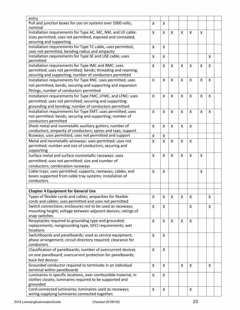
entry Pull and junction boxes for use on systems over 1000 volts, nominal
X X
Installation requirements for Type AC, MC, NM, and UF cable: Uses permitted, uses not permitted, exposed and concealed, securing and supporting
X X X X X X
Installation requirements for Type TC cable, uses permitted, uses not permitted, bending radius and ampacity
X X
Installation requirements for Type SE and USE cable, usespermitted
X X X
Installation requirements for Type IMC and RMC: uses permitted; uses not permitted; bends; threading and reaming; securing and supporting; number of conductors permitted
X X X X X X X
Installation requirements for Type RNC: uses permitted, uses not permitted, bends, securing and supporting and expansion fittings, number of conductors permitted
X X X X X X X
Installation requirements for Type FMC, LFMC, and LFNC: uses permitted; uses not permitted; securing and supporting; grounding and bonding; number of conductors permitted
X X X X X X X
Installation requirements for Type EMT: uses permitted; uses not permitted; bends; securing and supporting; number of conductors permitted
X X X X X X X
Sheet metal and nonmetallic auxiliary gutters; number of conductors; ampacity of conductors; spices and taps; support
X X X X X
Busways; uses permitted, uses not permitted and support X X Metal and nonmetallic wireways: uses permitted; uses not permitted; number and size of conductors; securing and supporting
X X X X X
Surface metal and surface nonmetallic raceways: uses permitted; uses not permitted; size and number of conductors; combination raceways
X X X X X X
Cable trays; uses permitted; supports; raceways, cables, and boxes supported from cable tray systems; installation of conductors
X X X
Chapter 4 Equipment for General Use Types of flexible cords and cables; ampacities for flexible cords and cables; uses permitted and uses not permitted
X X X X X X
Switch connections; enclosures not to be used as raceways; mounting height; voltage between adjacent devices; ratings of snap switches
X X X X
Receptacles required to grounding type and grounded; replacements, nongrounding type, GFCI requirements; wet locations
X X X X X
Switchboards and panelboards; used as service equipment; phase arrangement; circuit directory required; clearance for conductors
X X
Classification of panelboards; number of overcurrent devices on one panelboard; overcurrent protection for panelboards; back-fed devices
X X
Grounded conductor required to terminate in an individual terminal within panelboards
X X X X X
Luminaires in specific locations, over combustible material, in clothes closets; luminaires required to be supported and grounded
X X
Cord-connected luminaires; luminaires used as raceways; wiring supplying luminaires connected together;
X X X
2018 LicensingExaminationGuide Checked 20190102 23
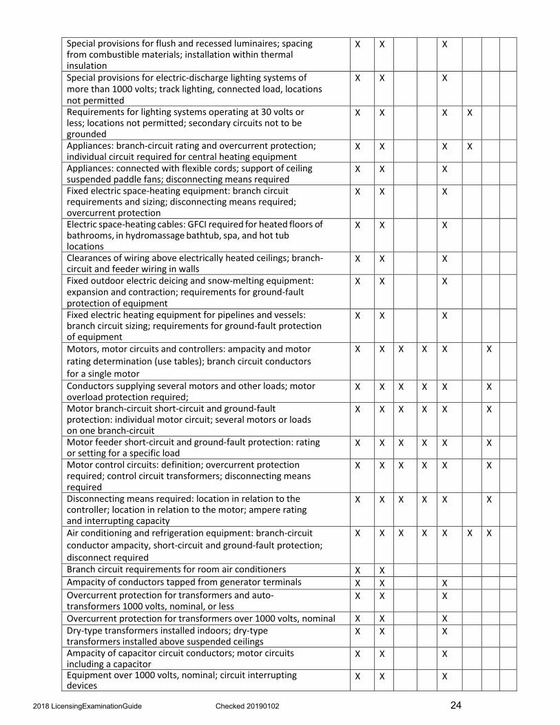
Special provisions for flush and recessed luminaires; spacing from combustible materials; installation within thermal insulation
X X X
Special provisions for electric-discharge lighting systems of more than 1000 volts; track lighting, connected load, locations not permitted
X X X
Requirements for lighting systems operating at 30 volts or less; locations not permitted; secondary circuits not to be grounded
X X X X
Appliances: branch-circuit rating and overcurrent protection; individual circuit required for central heating equipment
X X X X
Appliances: connected with flexible cords; support of ceiling suspended paddle fans; disconnecting means required
X X X
Fixed electric space-heating equipment: branch circuit requirements and sizing; disconnecting means required; overcurrent protection
X X X
Electric space-heating cables: GFCI required for heated floors of bathrooms, in hydromassage bathtub, spa, and hot tub locations
X X X
Clearances of wiring above electrically heated ceilings; branch-circuit and feeder wiring in walls
X X X
Fixed outdoor electric deicing and snow-melting equipment: expansion and contraction; requirements for ground-fault protection of equipment
X X X
Fixed electric heating equipment for pipelines and vessels: branch circuit sizing; requirements for ground-fault protection of equipment
X X X
Motors, motor circuits and controllers: ampacity and motor rating determination (use tables); branch circuit conductors for a single motor
X X X X X X
Conductors supplying several motors and other loads; motor overload protection required;
X X X X X X
Motor branch-circuit short-circuit and ground-fault protection: individual motor circuit; several motors or loads on one branch-circuit
X X X X X X
Motor feeder short-circuit and ground-fault protection: rating or setting for a specific load
X X X X X X
Motor control circuits: definition; overcurrent protection required; control circuit transformers; disconnecting means required
X X X X X X
Disconnecting means required: location in relation to the controller; location in relation to the motor; ampere rating and interrupting capacity
X X X X X X
Air conditioning and refrigeration equipment: branch-circuit conductor ampacity, short-circuit and ground-fault protection; disconnect required
X X X X X X X
Branch circuit requirements for room air conditioners X X Ampacity of conductors tapped from generator terminals X X X Overcurrent protection for transformers and auto-transformers 1000 volts, nominal, or less
X X X
Overcurrent protection for transformers over 1000 volts, nominal X X X Dry-type transformers installed indoors; dry-type transformers installed above suspended ceilings
X X X
Ampacity of capacitor circuit conductors; motor circuits including a capacitor
X X X
Equipment over 1000 volts, nominal; circuit interrupting devices
X X X
2018 LicensingExaminationGuide Checked 20190102 24
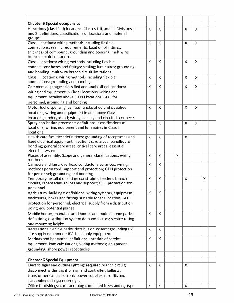
Chapter 5 Special occupancies Hazardous (classified) locations: Classes I, II, and III; Divisions 1 and 2; definitions, classifications of locations and material groups
X X X X
Class I locations: wiring methods including flexible connections; sealing requirements, location of fittings, thickness of compound, grounding and bonding; multiwire branch circuit limitations
X X X X
Class II locations: wiring methods including flexible connections; boxes and fittings; sealing; luminaires; grounding and bonding; multiwire branch circuit limitations
X X X X
Class III locations: wiring methods including flexible connections; grounding and bonding
X X X X
Commercial garages: classified and unclassified locations; wiring and equipment in Class I locations; wiring and equipment installed above Class I locations; GFCI for personnel; grounding and bonding
X X X X
Motor fuel dispensing facilities: unclassified and classified locations; wiring and equipment in and above Class I locations; underground; wiring; sealing and circuit disconnects
X X X X
Spray application processes: definitions; classifications of locations; wiring, equipment and luminaires in Class I locations
X X X X
Health care facilities: definitions; grounding of receptacles and fixed electrical equipment in patient care areas; panelboard bonding; general care areas; critical care areas; essential electrical systems
X X X
Places of assembly: Scope and general classifications; wiringmethods
X X X
Carnivals and fairs: overhead conductor clearances; wiring methods permitted, support and protection; GFCI protection for personnel; grounding and bonding
X X
Temporary installations: time constraints; feeders, branch circuits, receptacles, splices and support; GFCI protection for personnel
X X X X
Agricultural buildings: definitions; wiring systems, equipment enclosures, boxes and fittings suitable for the location; GFCI protection for personnel; electrical supply from a distribution point; equipotential planes
X X
Mobile homes, manufactured homes and mobile home parks: definitions; distribution system demand factors; service rating and mounting height
X X
Recreational vehicle parks: distribution system; grounding RV site supply equipment; RV site supply equipment
X X
Marinas and boatyards: definitions; location of service equipment; load calculations; wiring methods; equipment grounding; shore power receptacles
X X
Chapter 6 Special Equipment Electric signs and outline lighting: required branch circuit; disconnect within sight of sign and controller; ballasts, transformers and electronic power supplies in soffits and suspended ceilings; neon signs
X X X
Office furnishings: cord-and-plug connected freestanding-type X X X
2018 LicensingExaminationGuide Checked 20190102 25

partitions Elevators and escalators: live parts enclosed to protect against accidental contact; installation of conductors; minimum size of conductors; feeders and branch circuit conductors
X X X X
Elevators and escalators: wiring methods in hoistways, wellways and runways; branch circuit requirements for elevator cars, machine rooms, control rooms
X X X X
Elevators and escalators: number of conductors in wireways; supports for cables and raceways in hoistways, wellways and runways
X X X X
Elevators and escalators: requirements for disconnecting means and overcurrent protection; grounding and GFCI protection for personnel
X X X X X
Information technology equipment: special requirements for information technology equipment rooms; wiring methods under raised floors; disconnecting means required
X X X
Electrically driven or controlled irrigation machines: disconnecting means; grounding; bonding; methods of grounding
X X X X
Swimming pools, similar installations: definitions; clearance from overhead conductors; location and depths of underground wiring; wiring methods of permanently installed pools; area lighting, receptacles, and equipment
X X X
Swimming pools, similar installations: bonding of metallic structural components; common bonding grid; GFCI protectionfor personnel
X X
Spas and hot tubs: outdoor installations, wiring methods; indoor installations, locations of receptacles, luminaires, walls switches; bonding and grounding
X X
Solar photovoltaic systems: definitions; disconnecting means; wiring methods
X X X
Small wind electric systems X X Fire pumps X X
Chapter 7 Special Conditions Emergency systems: capacity and rating; separation from other wiring and equipment; sources of power
X X X X
Legally required standby systems: capacity and rating; sources of power
X X
Class 1, 2 and 3 remote-control signaling and power limited circuits: definitions; power source requirements; overcurrent protection; wiring methods; conductors of different systems in same raceway, enclosure, etc.; cable uses and permitted substitutions
X X X X X X
Class 1, 2 and 3 remote-control signaling and power limited circuits: abandoned cables; access to equipment of above suspended ceilings; remote-control circuits for safety-control equipment
X X X X
Fire alarm systems: non-power-limited and power-limited circuits
X X X X
Optical fibers cables and raceways: cables within buildings; cable markings; optical fibers installed with electrical conductors; cable substitutions
X X X
Critical operations power systems X X X X
Chapter 8 Communication Systems
2018 LicensingExaminationGuide Checked 20190102 26

Communication circuits: mechanical execution of work; protective devices; cable and primary protector grounding; raceways for wires and cables within buildings; cable markings, permitted uses and substitutions
X X X X X
Radio and television equipment: grounding receiving stations and metal support structures
X X X X
Community antenna television: ground cable shields; grounding methods and materials; cables installed within buildings; coaxial cable uses and permitted substitutions
X X X X
Network-powered broadband communication systems: wiring methods within buildings
X X X
Chapter 9 Tables Notes to tables: percent of cross section of raceways for conductors; use Annex C for conductors all the same size and insulation type; dimensions and percent area of conduit and tubing; dimensions of insulated conductors
X X X X X X X
Notes to tables: conductor properties; alternating-current resistance; Annex D, examples of branch-circuit, feeder, service, and motor circuit calculations; Annex E, types of construction
X X X X X
Notes to tables: class 2 and 3 alternating-current power source limitations
X X X
Applied Electrical Theory, Electrical Systems and Equipment General mathematics including transposing equations; calculating area, volume, and percentages
X X X X X X X X
Ohm’s law, Watt’s law, and voltage drop calculations X X X X X X X X Characteristics of series and parallel circuits X X X X X X Voltage, current, and power of single-phase and three-phase systems
X X X X X X X
Motor and transformer connections: single-phase; three-phase; transformer taps; wye and delta configurations; 115/230, 230/460 volt connections
X X X X X
Transformers: auto-transformers; short-circuit current available at secondary
X X X
Motor control circuits: three-wire, start-stop; start-stop-jog; control circuit transformers
X X X X
Power factor and power factor correction X X Trouble shooting common electrical problems X X X X X X X
2018 LicensingExaminationGuide Checked 20190102 27

A BRIEF SUMMARY OF YOUR RIGHTS UNDER AMERICAN DISABILITIES ACT
AMERICANS WITH DISABILITIES ACT INTRODUCTION The Americans with Disabilities Act (“ADA”) covers “public entities.” The Department of Labor and Industry (Department) is a “public entity” covered by the ADA. The Department may not refuse to allow a person with a disability to take the examination simply because the person has a disability. It must permit persons with disabilities to take the examination in an integrated setting unless separate or different measures are necessary to ensure equal opportunity. It must eliminate unnecessary eligibility standards or rules that deny individuals with disabilities an equal opportunity to take the examination.
WHO IS COVERED? The ADA provides comprehensive civil rights protection for “qualified individuals with disabilities.” An “individual with a disability” is a person who: 1) has a physical or mental impairment that substantially limits a “major life activity,” 2) has a record of such an impairment, or 3) is regarded as having such an impairment. “Major life activities” include functions such as caring for oneself, performing manual tasks, walking, seeing, hearing, speaking, breathing, learning, and working.
Individuals who currently engage in the illegal use of drugs are not protected by the ADA when an action is taken on the basis of their current illegal use of drugs.
A “qualified” individual with a disability is one who meets the essential eligibility requirements for the examination. The Department is not required to take any action that would result in a fundamental alteration in the nature of the examination or an undue financial and administrative burden. However, the Department must take any other action, if available, that would not result in a fundamental alteration or undue burdens but would ensure that individuals with disabilities receive the benefits or services.
WHAT IS REQUIRED? The Department is required to make reasonable modifications in any policies, practices, and procedures that deny equal access to individuals with disabilities, unless a fundamental alteration in the examination would result. To do so, it must furnish auxiliary aids and services when necessary to ensure effective communication, unless an undue burden or fundamental alteration would result. The Department may not place special charges on individuals with disabilities to cover the costs of measures necessary to ensure nondiscriminatory treatment, such as making modifications required to provide program accessibility or providing qualified interpreters. Finally, it must operate the examination so that, when viewed in its entirety, it is readily accessible to and usable by individuals with disabilities.
Integration of individuals with disabilities into the mainstream of society is fundamental to the purposes of the ADA. The Department may not provide the examination to individuals with disabilities through programs that are separate or different, unless the separate programs are necessary to ensure that the benefits and services are equally effective. Even when separate programs are permitted, an individual with a disability still has the right to choose to participate in the regular program. The Department cannot require an individual with a disability to accept a special accommodation or benefit if the individual chooses not to accept it.
QUESTIONS? If you have any questions about the ADA we encourage you to contact the United States Department of Justice which as an ADA information line, at https://www.ada.gov/infoline.htm
2018 LicensingExaminationGuide Checked 20190102 28

INFORMATION ABOUT THE EXAMINATIONS AND AVAILABILITY OF ALTERNATIVE ARRANGEMENTS FOR PERSONS WITH DISABILITIES
GENERAL INFORMATION If you are a person with a disability, you have certain rights under the Americans with Disabilities Act (“ADA”). A brief summary of these rights is on the back of this sheet. It is not meant to be complete. If you have any questions about the ADA we encourage you to contact the United States Department of Justice which as an ADA information line, at https://www.ada.gov/infoline.htm
ABOUT THE EXAMINATIONS A copy of the License Examination Guide may be obtained from the Department’s website at: http://www.dli.mn.gov/sites/default/files/pdf/LicensingExaminationGuide.pdf
Examinations are held weekly, generally every Saturday, at the Department of Labor and Industry Building located at 443 Lafayette Road North, Saint Paul, just north of the intersection of Interstate 94 and US Highway 52 (Lafayette Road North), on the northeast edge of downtown Saint Paul. The building is accessible to persons with physical disabilities.
Specify instructions for scheduling and appearing for an examination are included in the letter that is sent to approved applicants.
ALTERNATIVE ARRANGEMENTS The ADA requires this agency to make “reasonable accommodations” for applicants with disabilities in giving the examinations. If you are a person with a disability which may affect your ability to enter the examination facility or to take any portion of the examination, the ADA may require the agency to provide alternative examination arrangements. We are not required to do so if we are unaware of your need for alternatives. Based on the above description of the examination facilities and the examination itself, we ask that you inform us of any alternative arrangements you may require to take the examination. Please describe in detail:
(Use additional paper if necessary and attach to this form)
SIGNATURE DATE IF YOU ARE REQUESTING ALTERNATIVE ARRANGEMENTS BASED ON A DISABILITY, PLEASE SUBMIT THIS FORM WITH YOUR APPLICATION FOR EXAMINATION FORM.
2018 LicensingExaminationGuide Checked 20190102 29

Scheduling Examinations Before anyone may schedule an examination date, the individual’s examination application must be approved by DLI. There are no exceptions.
Dates scheduled by individuals without written approval of their application will be rejected and not scheduled. Individuals retesting after a failed exam must apply for another examination date.
Detailed exam dates, location and scheduling information can be accessed at: http://www.dli.mn.gov/business/get-licenses-and-permits/license-exam-schedule
Applicants must schedule their examinations ahead of time. Walk-ins are not permitted to take an examination. Applicants may reschedule their examination one time. Applicants that fail to appear for a rescheduled examination as well as applicants that fail their examination must submit a new application and examination fee before being approved for examination or reexamination.
All examination types administered at the St. Paul office begin at 8:15 a.m. and end at 1:45.
All examination types are allotted 5½ hours for completion. All applicants should arrive at the examination site not later than 30 minutes before their scheduled starting time. A picture ID must be presented by all applicants when they appear for examination.
Note: Food and drink are permitted during the exam. Use of restrooms is permitted. However, applicants are not allowed to leave the building once the exam has started.
The Department of Labor and Industry Building located at 443 Lafayette Road North, Saint Paul, just north of the intersection of Interstate 94 and US Highway 52 (Lafayette Road North), on the northeast edge of downtown Saint Paul. http://www.mapquest.com/maps/map.adp?country=US&addtohistory=&formtype=address&searchtyp e=address&cat=&address=443%20Lafayette%20Rd%20N&city=Saint%20Paul&state=MN&zipcode= 55155%2d4301
Specific instructions concerning the examinations in St. Paul are sent as a part of the “Approved for Examination” letter and specific instructions for out-state sites are sent to persons who schedule at those sites.
2018 LicensingExaminationGuide Checked 20190102 30

Qualifications for LicenseApplicants Electrical Engineering Degree
Applicants who have received a Bachelor’s degree in Electrical Engineering from an accredited university or college qualify for the Class A master electrician and power limited technician examinations without being required to have any practical installation experience. “Engineer” applicants should include a copy of their transcript or diploma with their application.
Technical College Program Credit
Applicants for Class A journeyworker electrician, maintenance electrician, power limited technician, and Class B installer who have successfully completed a two-year technical college program approved by the Department receive 12-month’s experience credit toward the experience required for the class of license applied for.
Applicants for a power limited technician license who have completed other technical training approved by the Department receive up to 12-month’s experience credit toward the 36 month experience requirement. Technical training credit is only granted for successful completion of programs approved by the Department prior to completion by the applicant. Technical training credit is not approved on an individual applicant basis.
Practical experience credit is not granted for work performed during the time period the applicant attended a two-year technical college program.
Military Experience
Applicants may receive experience credit for performing electrical work in the military. Applicants with military experience should include a copy of their DD214 discharge documents with their application.
Practical Experience/Experience Requirements by License Type
Minnesota Rule 3800.3520 identifies allowable experience credit, situations under which experience is acceptable to the Department, and experience requirements for all license categories. Applicants are encouraged to review these requirements prior to submitting an application.
Application/examination fees for applicants that do not qualify for examination are not refundable.
Minnesota Rule 3800.3520 can be accessed at: https://www.revisor.mn.gov/rules/3800/
Qualification for Satellite System Installer Applicants
Applicants for a satellite system installer license are not required to have any practical experience, rather are required to have successfully completed the National Standards and Testing Program for satellite system installers sponsored by the Satellite Broadcasting and Communications Association of America, Inc. or other program approved by the Board of Electricity.
2018 LicensingExaminationGuide Checked 20190102 31

Obtaining Licenses Through Reciprocal Agreements Minnesota has established reciprocal licensing agreements with a number of other states where by applicants may obtain a journeyworker or master electrician license in the participating states if they obtained their license by examination in the participating states.
Minnesota has agreements at the journeyworker electrician level with the following states: Alaska, Arkansas, Colorado, Iowa, Montana, Nebraska, North Dakota, South Dakota, and Wyoming. In addition, Minnesota, Iowa, North Dakota, Nebraska, and South Dakota have reciprocal agreements at the master electrician license level.
Qualifying conditions include the following:
1. The applicant must meet the qualifications for license examination in the state they are makingapplication.
2. The applicant must not have failed the same or greater class of license examination in the stateapplication is made.
3. The applicant must have obtained the same or greater class of license in the first state byexamination at the state level (the license must not have been obtained through a reciprocalagreement or grandfather clause with a city or other political subdivision).
4. The applicant must have received an examination score equal to or greater than required in thestate application is made.
5. The applicant must have held the license for at least one year in the first state.
6. The applicant’s license must be current and in good standing in the first state.
7. The applicant must not be under any order to deny, suspend, or revoke any class of electricallicense in Minnesota.
8. The applicant must submit an application and examination fee with the application.
9. Upon approval, the applicant must submit the required license fee to be issued the license appliedfor.
10. Upon obtaining the license, the applicant (licensee) must meet all continuing education andrenewal requirements to maintain the license.
2018 LicensingExaminationGuide Checked 20190102 32

Continuing EducationRequirements Upon obtaining a license, the license holder must earn minimum continuing education credits to renew and maintain a license. Because it is not a required license, lineman license holders are not required to meet any continuing education requirements to renew and maintain their license.
Except for power limited technician licenses, all other personal licenses require the license holder to earn a minimum of 16 hours of continuing education credit prior to renewal. Of these 16 hours, at least 12 hours must be on the National Electrical Code, and up to 4 hours may be on related technical subjects or the Minnesota Electrical Act and Minnesota Rules Chapters 3800 and 3801.
Power limited technicians are required to earn 16 hours of continuing education credit, 4 hours of which must be on the National Electrical Code and up to 12 hours may be on related technical subjects or the Minnesota Electrical Act and Minnesota Rules Chapters 3800 and 3801.
Satellite system installers are required to earn 4 hours of continuing education credit.
Holders of master electrician licenses, which have fixed terms, are not required to meet any continuing education requirements in their first pro-rated term, but must earn 16 hours in all subsequent terms.
Continuing education credits may be used for renewal of more than one class of license, but may only be used once for each class of license. Continuing education credits in excess of those required for renewal and earned prior to expiration of a license do not carry over to the next license term.
Continuing education credit is only received for verified attendance/completion of programs granted Department approval. Continuing education credit may be received by attending programs approved in other states where the programs meet Department requirements.
Continuing education requirements are found in Minnesota Rule 3800.3600-3603. Lists of Department approved continuing education providers are available under “continuing education” at: http://www.dli.mn.gov/workers/electrician-or-electrical-installer/continuing-education-electrical
Personal License and Examination Application Personal license applications are included in the hard-copy packet or may be downloaded fromthe Department’s website at: http://www.dli.mn.gov/workers/electrician-or-electrical-installer/licensing-personal-electrical-license
Laws and Rules Regulating Licensing of Electricians and Inspection of Electrical Installations
A copy of the Minnesota Electrical Act and Minnesota Rules Chapter 3800 and 3801 are included in the hard- copy packet or may be downloaded from the Department’s website at: http://www.dli.mn.gov/business/electrical-contractors/electrical-laws-and-rules
Upon request this document can be made available in alternative formats for people with disabilities.
2018 LicensingExaminationGuide Checked 20190102 33