
Electrical Installation Guide - Iec Standards Compliant 2005
391
Technical Series Electrical installation guide According to IEC International Standards . . . . . . . . . . . . . . . . . . . . . . New edition 2005 http://theguide.merlin-gerin.com Zoom in zone Directions for use: In order to browse through this document easily, we advise you to use the bookmarks, to choose a "full screen" view: "Ctrl+L" and, if possible, to choose following parameters for the screen resolution: 1024x768. Full text search is possible: see notice of CD-ROM.
Transcript of Electrical Installation Guide - Iec Standards Compliant 2005
Technical Series
Electricalinstallation guideAccording to IEC International Standards
. . . . . . . . . . . . . . . . . . . . . .
New edition
2005http://theguide.merlin-gerin.com
Zoom in zone
Directions for use:In order to browse through this document easily, we advise you to usethe bookmarks, to choose a "full screen" view: "Ctrl+L" and, if possible,to choose following parameters for the screen resolution: 1024x768.Full text search is possible: see notice of CD-ROM.
Price: 90 €ISBN : 2-907314-47-5N° dépôt légal: 1er semestre 2005Conseil © Schneider ElectricAll rights reserved for all the countries
This technical guide is the result ofa collective effort.
Technical advisor:Serge Volut
Design/Technical content:Guy Satre-Duplessis
Illustrations and production:AXESS - Valence -France
Printing:Les Deux Ponts - France
Second editionMarch 2005
The Electrical Installation Guide is a single document covering thetechniques, regulations and standards related to electrical installations.It is intended for electrical professionals in companies, design offices,inspection organisations, etc.
Electrical equipment should be serviced only by qualified electricalmaintenance personnel, and this document should not be viewed assufficient instructions for those who are not otherwise qualified to operate,service or maintain the equipment discussed. Although reasonable carehas been taken to provide accurate and authoritative information in thisdocument, no responsibility is assumed by Schneider Electric for anyconsequences arising from the use of this material.
This new edition has been published to take into account changes intechniques, standards and regulations, in particular electrical installationstandard IEC 60364.
We thank all the readers of the previous edition of this guide for theircomments that have helped improve the current edition.We also thank the many people and organisations, to numerous to namehere, who have contributed in one way or another to the preparation ofthis guide.
This guide has been written for electrical Engineers who have to design,realize, inspect or maintain electrical installations in compliance withinternational Standards of the International ElectrotechnicalCommission (IEC).“Which technical solution will guarantee that all relevant safety rules aremet?” This question has been a permanent guideline for the elaboration ofthis document.
An international Standard such as the IEC 60364 “Electrical Installation inBuldings” specifies extensively the rules to comply with to ensure safetyand predicted operational characteristics for all types of electricalinstallations. As the Standard must be extensive, and has to be applicableto all types of products and the technical solutions in use worldwide, thetext of the IEC rules is complex, and not presented in a ready-to-useorder. The Standard cannot therefore be considered as a workinghandbook, but only as a reference document.
The aim of the present guide is to provide a clear, practical and step-by-step explanation for the complete study of an electrical installation,according to IEC 60364 and other relevant IEC Standards. Therefore, thefirst chapter (B) presents the methodology to be used, and each chapterdeals with one out of the eight steps of the study. The two last chapter aredevoted to particular supply sources, loads and locations, and appendixprovides additional information. Special attention must be paid to theEMC appendix, which is based on the broad and practical experience onelectromagnetic compatibility problems.
We all hope that you, the user, will find this handbook genuinely helpful.
Schneider Electric S.A.

Foreword
Roland Talon, Chairman TC 64 - International Electrotechnical Commission
It is generally agreed that electrical equipment will provide the best
performance (safety, operation and service life) when it is properly
installed, which includes good co-ordination.
The task of Technical Committee 64 of the IEC (International
Electrotechnical Commission) is to develop and keep up-to-date
requirements for electrical installations. TC64 also has a Safety Pilot
Function for installations, equipment, products and systems. Delegates
from many National Committees work in TC 64, drawn from
manufacturers, laboratories, verification bodies, installers, and electrical
power supply companies...
…with the consequence that IEC Standard 60364 is considered as the
definitive document on which to base the design and implementation of an
electrical installation.
Furthermore the electrical environment is increasingly complex, mainly
due to electromagnetic influences and other kinds of disturbances, and
the continuous operation of all equipment supplied by the electrical
installation has become a fundamental requirement.
Consequently designers, installers and consumers need guidance on the
selection and installation of electrical equipment.
With this in mind, Schneider Electric has developed this Electrical
Installation Guide. It has been prepared by engineers from Schneider
Electric who are very experienced in electrical installation technology and
possess excellent knowledge of consumer problems and requirements,
and of IEC Standard 60364 and other relevant IEC standards.
Last but not least, this Electrical Installation Guide has adopted the IEC
Standard 60364 as a basis and as a result facilitates and favours
international trade.
As TC 64 Chairman and formerly the representative of French Electrical
Contractors on TC64, it is my great pleasure and honour to introduce this
guide. I am sure it will prove very useful in the implementation of the
provisions of 60364 and in meeting consumers’ concerns.
Roland Talon has been with the French ElectricalContractors’ Association (FFIE) for 20 years.He previously worked for electrical contractingcompanies. During that period, he was deeplyinvolved in many international projects.
Roland Talon has been Chairman of IEC TC 64since 2002 as well as chairman of CENELEC TC64.
Schneider Electric - Electrical installation guide 2004Schneider Electric - Electrical installation guide 2004
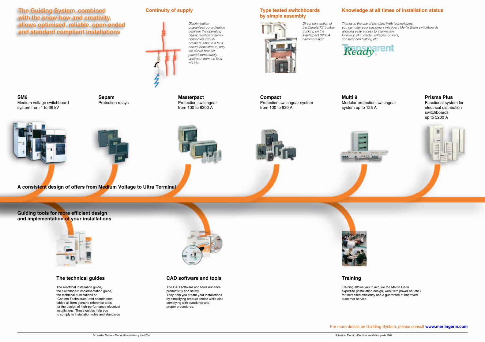
Continuity of supply Type tested switchboardsby simple assembly
Knowledge at all times of installation status
Discriminationguarantees co-ordinationbetween the operatingcharacteristics of serial-connected circuit-breakers. Should a faultoccurs downstream, onlythe circuit-breakerplaced immediatelyupstream from the faultwill trip.
Direct connection ofthe Canalis KT busbartrunking on theMasterpact 3200 Acircuit-breaker
SM6Medium voltage switchboardsystem from 1 to 36 kV
SepamProtection relays
MasterpactProtection switchgearfrom 100 to 6300 A
CompactProtection switchgear systemfrom 100 to 630 A
Multi 9Modular protection switchgearsystem up to 125 A
Prisma PlusFunctional system forelectrical distributionswitchboardsup to 3200 A
The technical guides
The electrical installation guide,the switchboard implementation guide,the technical publications or“Cahiers Techniques” and coordinationtables all form genuine reference toolsfor the design of high-performance electricalinstallations. These guides help youto comply to installation rules and standards
CAD software and tools
The CAD software and tools enhanceproductivity and safety.They help you create your installationsby simplifying product choice while alsocomplying with standards andproper procedures.
Training
Training allows you to acquire the Merlin Gerinexpertise (installation design, work with power on, etc.)for increased efficiency and a guarantee of improvedcustomer service.
A consistent design of offers from Medium Voltage to Ultra Terminal
For more details on Guilding System, please consult www.merlingerin.com
Guiding tools for more efficient designand implementation of your installations
Thanks to the use of standard Web technologies,you can offer your customers intelligent Merlin Gerin switchboardsallowing easy access to information:follow-up of currents, voltages, powers,consumption history, etc.
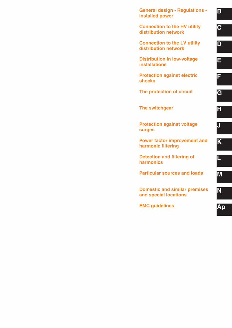
General design - Regulations -Installed power
B
C
D
E
F
G
H
J
K
L
M
N
Ap
Connection to the HV utilitydistribution network
Connection to the LV utilitydistribution network
Distribution in low-voltageinstallations
Protection against electricshocks
The protection of circuit
The switchgear
Protection against voltagesurges
Power factor improvement andharmonic filtering
Detection and filtering ofharmonics
Particular sources and loads
Domestic and similar premisesand special locations
EMC guidelines
Schneider Electric - Electrical installation guide 2005
A
General design - Regulations - Installed power1 Methodology B2
2 Rules and statutory regulations B4
3 Installed power loads - Characteristics B10
4 Power loading of an installation B15
5 Power monitoring and control B21
Connection to the HV utility distribution network1 Supply of power at high voltage C2
2 Procedure for the establishment of a new substation C14
3 Protection aspect C16
4 The consumer substation with LV metering C22
5 The consumer substation with HV metering C30
6 Constitution of HV/LV distribution substations C35
Connection to the LV utility distribution network1 Low voltage utility distribution networks D2
2 Tariffs and metering D16
Distribution in low-voltage installations1 LV distribution schemes E2
2 Earthing schemes E17
3 The installation system E30
4 External influences (IEC 60364-5-51) E38
Protection against electric shocks1 General F2
2 Protection against direct contact F4
3 Protection against indirect contact F6
4 Protection of goods due to insulation fault F17
5 Implementation of the TT system F19
6 Implementation of the TN system F25
7 Implementation of the IT system F31
8 Residual current differential devices (RDCs) F38
The protection of circuits1 General G2
2 Practical method for determining the smallest allowable G11cross-sectional area of circuit conductors
3 Determination of voltage drop G19
4 Short-circuit current G23
5 Particular cases of short-circuit current G29
6 Protective earthing conductor G36
7 The neutral conductor G41
The switchgear1 The basic functions of LV switchgear H2
2 The switchgear H5
3 Choice of switchgear H10
4 Circuit breaker H11
B
C
D
E
F
G
H
General contents
Schneider Electric - Electrical installation guide 2005
A
Protection against voltage surges1 General J2
2 Overvoltage protection devices J6
3 Standards J11
4 Choosing a protection device J14
Power factor improvement and harmonic filtering1 Reactive energy and power factor K2
2 Why to improve the power factor? K5
3 How to improve the power factor K7
4 Where to install power correction capacitors K10
5 How to decide the optimum level of compensation K12
6 Compensation at the terminals of a transformer K15
7 Power factor improvement of induction motors K18
8 Example of an installation before and after power-factor correction K20
9 The effects of harmonics K21
10 Implementation of capacitor banks K24
Detection and filtering of harmonics1 The problem: L2Why is it necessary to detect and eliminate harmonics?
2 Standards L3
3 General L4
4 Main effects of harmonics in installations L6
5 Essential indicators of harmonic distortion and L11measurement principles
6 Measuring the indicators L14
7 Detection devices L16
8 Solutions to attenuate harmonics L17
Particular sources and loads1 Protection of a LV generator set and the downstream circuits M2
2 Uninterruptible Power Supply Units (UPS) M11
3 Protection of LV/LV transformers M24
4 Lighting circuits M27
5 Asynchronous motors M42
Domestic and similar premises and special locations1 Domestic and similar premises N2
2 Bathrooms and showers N8
3 Recommendations applicable to special installations and locations N12
EMC guidelines1 Electrical distribution Ap2
2 Earthing principles and structures Ap3
3 Implementation Ap5
4 Coupling mechanism and counter-measures Ap14
5 Wiring recommendations Ap20
General contents
J
K
L
M
N
Appendix
B1
Schneider Electric - Electrical installation guide 2005
Chapter BGeneral design - Regulations -Installed power
Contents
Methodology B2
Rules and statutory regulations B4
2.1 Definition of voltage ranges B4
2.2 Regulations B5
2.3 Standards B5
2.4 Quality and safety of an electrical installation B6
2.5 Initial testing of an installation B6
2.6 Periodic check-testing of an installation B7
2.7 Conformity (with standards and specifications) of equipmentused in the installation B7
2.8 Environment B8
Installed power loads - Characteristics B10
3.1 Induction motors B10
3.2 Resistive-type heating appliances and incandescent lamps(conventional or halogen) B12
Power loading of an installation B15
4.1 Installed power (kW) B15
4.2 Installed apparent power (kVA) B15
4.3 Estimation of actual maximum kVA demand B18
4.4 Example of application of factors ku and ks B17
4.5 Diversity factor B18
4.6 Choice of transformer rating B19
4.7 Choice of power-supply sources B20
Power monitoring and control B21
5.1 Main user’s benefits B21
5.2 From Network Monitoring and Control System toIntelligent Power Equipment B23
5.3 Typical services possibly brought by intelligent equipmentcompared to other solutions B25
5.4 Technical inputs on communicating systems B26
5.5 Main constraints to take into account to designa communicating or intelligent power equipment B27
12
3
4
5
Schneider Electric - Electrical installation guide 2005
B2 B - General design - Regulations -Installed power
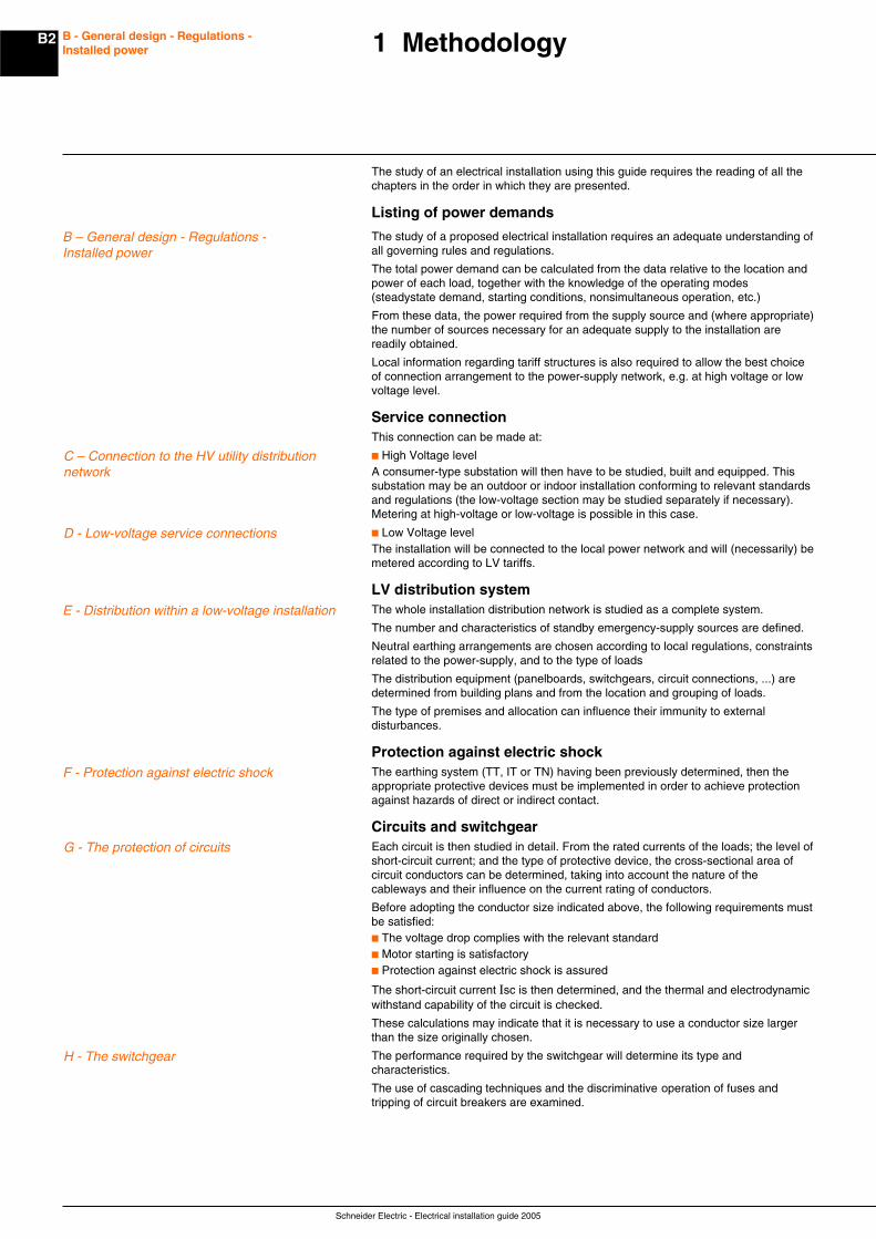
The study of an electrical installation using this guide requires the reading of all thechapters in the order in which they are presented.
Listing of power demands
The study of a proposed electrical installation requires an adequate understanding ofall governing rules and regulations.
The total power demand can be calculated from the data relative to the location andpower of each load, together with the knowledge of the operating modes(steadystate demand, starting conditions, nonsimultaneous operation, etc.)
From these data, the power required from the supply source and (where appropriate)the number of sources necessary for an adequate supply to the installation arereadily obtained.
Local information regarding tariff structures is also required to allow the best choiceof connection arrangement to the power-supply network, e.g. at high voltage or lowvoltage level.
Service connectionThis connection can be made at:
c High Voltage levelA consumer-type substation will then have to be studied, built and equipped. Thissubstation may be an outdoor or indoor installation conforming to relevant standardsand regulations (the low-voltage section may be studied separately if necessary).Metering at high-voltage or low-voltage is possible in this case.
c Low Voltage levelThe installation will be connected to the local power network and will (necessarily) bemetered according to LV tariffs.
LV distribution systemThe whole installation distribution network is studied as a complete system.
The number and characteristics of standby emergency-supply sources are defined.
Neutral earthing arrangements are chosen according to local regulations, constraintsrelated to the power-supply, and to the type of loads
The distribution equipment (panelboards, switchgears, circuit connections, ...) aredetermined from building plans and from the location and grouping of loads.
The type of premises and allocation can influence their immunity to externaldisturbances.
Protection against electric shockThe earthing system (TT, IT or TN) having been previously determined, then theappropriate protective devices must be implemented in order to achieve protectionagainst hazards of direct or indirect contact.
Circuits and switchgearEach circuit is then studied in detail. From the rated currents of the loads; the level ofshort-circuit current; and the type of protective device, the cross-sectional area ofcircuit conductors can be determined, taking into account the nature of thecableways and their influence on the current rating of conductors.
Before adopting the conductor size indicated above, the following requirements mustbe satisfied:c The voltage drop complies with the relevant standardc Motor starting is satisfactoryc Protection against electric shock is assured
The short-circuit current Isc is then determined, and the thermal and electrodynamicwithstand capability of the circuit is checked.
These calculations may indicate that it is necessary to use a conductor size largerthan the size originally chosen.
The performance required by the switchgear will determine its type andcharacteristics.
The use of cascading techniques and the discriminative operation of fuses andtripping of circuit breakers are examined.
1 Methodology
B – General design - Regulations -Installed power
C – Connection to the HV utility distributionnetwork
D - Low-voltage service connections
E - Distribution within a low-voltage installation
F - Protection against electric shock
G - The protection of circuits
H - The switchgear

B3
Schneider Electric - Electrical installation guide 2005
B - General design - Regulations -Installed power
Protection against overvoltagesDirect or indirect lightning strokes can damage electrical equipment at a distance ofseveral kilometers. Operating voltage surges and transient industrial frequencyvoltage surges can also produce the same consequences.The effects areexaminated and solutions are proposed.
Reactive energyThe power factor correction within electrical installations is carried out locally,globally or as a combination of both methods.
HarmonicsHarmonics in the network affect the quality of energy and are at the origin of manypollutions as overloads, vibrations, ageing of equipment, trouble of sensitiveequipment, of local area networks, telephone networks. This chapter deals with theorigins and the effects of harmonics and explain how to measure them and presentthe solutions.
Particular supply sources and loadsParticular items or equipment are studied:c Specific sources such as alternators or invertersc Specific loads with special characteristics, such as induction motors, lightingcircuits or LV/LV transformersc Specific systems, such as direct-current networks
Generic applicationsCertain premises and locations are subject to particularly strict regulations: the mostcommon example being domestic dwellings.
Ecodial softwareEcodial software(1) provides a complete design package for LV installations, inaccordance with IEC standards and recommendations.
The following features are included:c Construction of one-line diagramsc Calculation of short-circuit currentsc Calculation of voltage dropsc Optimization of cable sizesc Required ratings of switchgear and fusegearc Discrimination of protective devicesc Recommendations for cascading schemesc Verification of the protection of personsc Comprehensive print-out of the foregoing calculated design data
J – Protection against overvoltages
K - Power factor improvement and harmonicfiltering
M - Particular supply sources and loads
N - Domestic and similar premises and speciallocations
L - Harmonics detection and filtering
(1) Ecodial is a Merlin Gerin product and is available in Frenchand English versions.
1 Methodology
Schneider Electric - Electrical installation guide 2005
B4 B - General design - Regulations -Installed power
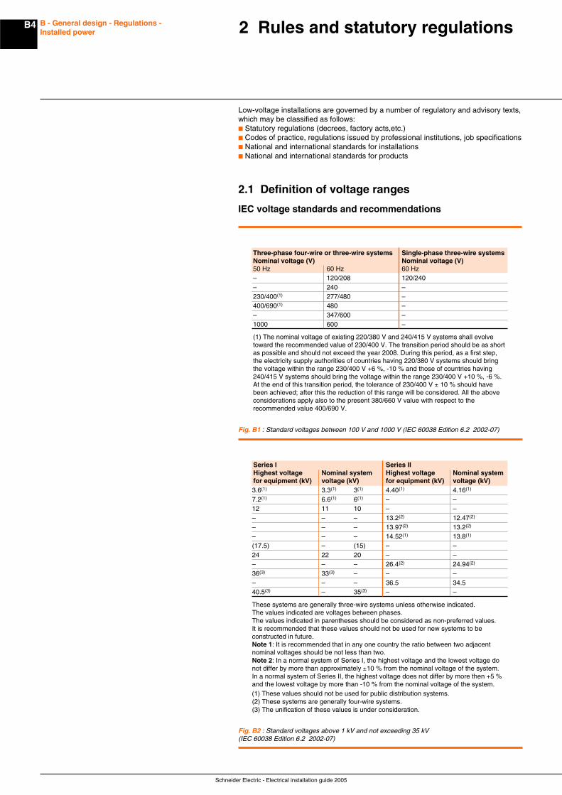
Low-voltage installations are governed by a number of regulatory and advisory texts,which may be classified as follows:c Statutory regulations (decrees, factory acts,etc.)c Codes of practice, regulations issued by professional institutions, job specificationsc National and international standards for installationsc National and international standards for products
2.1 Definition of voltage ranges
IEC voltage standards and recommendations
2 Rules and statutory regulations
Three-phase four-wire or three-wire systems Single-phase three-wire systemsNominal voltage (V) Nominal voltage (V)50 Hz 60 Hz 60 Hz– 120/208 120/240– 240 –230/400(1) 277/480 –400/690(1) 480 –– 347/600 –1000 600 –
(1) The nominal voltage of existing 220/380 V and 240/415 V systems shall evolvetoward the recommended value of 230/400 V. The transition period should be as shortas possible and should not exceed the year 2008. During this period, as a first step,the electricity supply authorities of countries having 220/380 V systems should bringthe voltage within the range 230/400 V +6 %, -10 % and those of countries having240/415 V systems should bring the voltage within the range 230/400 V +10 %, -6 %.At the end of this transition period, the tolerance of 230/400 V ± 10 % should havebeen achieved; after this the reduction of this range will be considered. All the aboveconsiderations apply also to the present 380/660 V value with respect to therecommended value 400/690 V.
Fig. B1 : Standard voltages between 100 V and 1000 V (IEC 60038 Edition 6.2 2002-07)
Series I Series IIHighest voltage Nominal system Highest voltage Nominal systemfor equipment (kV) voltage (kV) for equipment (kV) voltage (kV)3.6(1) 3.3(1) 3(1) 4.40(1) 4.16(1)
7.2(1) 6.6(1) 6(1) – –12 11 10 – –– – – 13.2(2) 12.47(2)
– – – 13.97(2) 13.2(2)
– – – 14.52(1) 13.8(1)
(17.5) – (15) – –24 22 20 – –– – – 26.4(2) 24.94(2)
36(3) 33(3) – – –– – – 36.5 34.540.5(3) – 35(3) – –
These systems are generally three-wire systems unless otherwise indicated.The values indicated are voltages between phases.The values indicated in parentheses should be considered as non-preferred values.It is recommended that these values should not be used for new systems to beconstructed in future.Note 1: It is recommended that in any one country the ratio between two adjacentnominal voltages should be not less than two.Note 2: In a normal system of Series I, the highest voltage and the lowest voltage donot differ by more than approximately ±10 % from the nominal voltage of the system.In a normal system of Series II, the highest voltage does not differ by more then +5 %and the lowest voltage by more than -10 % from the nominal voltage of the system.(1) These values should not be used for public distribution systems.(2) These systems are generally four-wire systems.(3) The unification of these values is under consideration.
Fig. B2 : Standard voltages above 1 kV and not exceeding 35 kV(IEC 60038 Edition 6.2 2002-07)
B5
Schneider Electric - Electrical installation guide 2005
B - General design - Regulations -Installed power
2.2 Regulations
In most countries, electrical installations shall comply with more than one set ofregulations, issued by National Authorities or by recognized private bodies. It isessential to take into account these local constraints before starting the design.
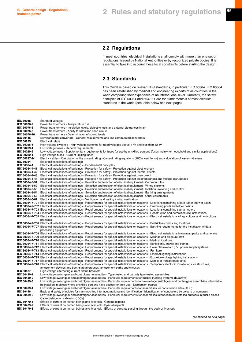
2.3 Standards
This Guide is based on relevant IEC standards, in particular IEC 60364. IEC 60364has been established by medical and engineering experts of all countries in theworld comparing their experience at an international level. Currently, the safetyprinciples of IEC 60364 and 60479-1 are the fundamentals of most electricalstandards in the world (see table below and next page).
IEC 60038 Standard voltagesIEC 60076-2 Power transformers - Temperature riseIEC 60076-3 Power transformers - Insulation levels, dielectric tests and external clearances in airIEC 60076-5 Power transformers - Ability to withstand short circuitIEC 60076-10 Power transformers - Determination of sound levelsIEC 60146 Semiconductor convertors - General requirements and line commutated convertorsIEC 60255 Electrical relaysIEC 60265-1 High-voltage switches - High-voltage switches for rated voltages above 1 kV and less than 52 kVIEC 60269-1 Low-voltage fuses - General requirementsIEC 60269-2 Low-voltage fuses - Supplementary requirements for fuses for use by unskilled persons (fuses mainly for household and similar applications)IEC 60282-1 High-voltage fuses - Current-limiting fusesIEC 60287-1-1 Electric cables - Calculation of the current rating - Current rating equations (100% load factor) and calculation of losses - GeneralIEC 60364 Electrical installations of buildingsIEC 60364-1 Electrical installations of buildings - Fundamental principlesIEC 60364-4-41 Electrical installations of buildings - Protection for safety - Protection against electric shockIEC 60364-4-42 Electrical installations of buildings - Protection for safety - Protection against thermal effectsIEC 60364-4-43 Electrical installations of buildings - Protection for safety - Protection against overcurrentIEC 60364-4-44 Electrical installations of buildings - Protection for safety - Protection against electromagnetic and voltage disrurbanceIEC 60364-5-51 Electrical installations of buildings - Selection and erection of electrical equipment - Common rulesIEC 60364-5-52 Electrical installations of buildings - Selection and erection of electrical equipment - Wiring systemsIEC 60364-5-53 Electrical installations of buildings - Selection and erection of electrical equipment - Isolation, switching and controlIEC 60364-5-54 Electrical installations of buildings - Selection and erection of electrical equipment - Earthing arrangementsIEC 60364-5-55 Electrical installations of buildings - Selection and erection of electrical equipment - Other equipmentsIEC 60364-6-61 Electrical installations of buildings - Verification and testing - Initial verificationIEC 60364-7-701 Electrical installations of buildings - Requirements for special installations or locations - Locations containing a bath tub or shower basinIEC 60364-7-702 Electrical installations of buildings - Requirements for special installations or locations - Swimming pools and other basinsIEC 60364-7-703 Electrical installations of buildings - Requirements for special installations or locations - Locations containing sauna heatersIEC 60364-7-704 Electrical installations of buildings - Requirements for special installations or locations - Construction and demolition site installationsIEC 60364-7-705 Electrical installations of buildings - Requirements for special installations or locations - Electrical installations of agricultural and horticultural
premisesIEC 60364-7-706 Electrical installations of buildings - Requirements for special installations or locations - Restrictive conducting locationsIEC 60364-7-707 Electrical installations of buildings - Requirements for special installations or locations - Earthing requirements for the installation of data
processing equipmentIEC 60364-7-708 Electrical installations of buildings - Requirements for special installations or locations - Electrical installations in caravan parks and caravansIEC 60364-7-709 Electrical installations of buildings - Requirements for special installations or locations - Marinas and pleasure craftIEC 60364-7-710 Electrical installations of buildings - Requirements for special installations or locations - Medical locationsIEC 60364-7-711 Electrical installations of buildings - Requirements for special installations or locations - Exhibitions, shows and standsIEC 60364-7-712 Electrical installations of buildings - Requirements for special installations or locations - Solar photovoltaic (PV) power supply systemsIEC 60364-7-713 Electrical installations of buildings - Requirements for special installations or locations - FurnitureIEC 60364-7-714 Electrical installations of buildings - Requirements for special installations or locations - External lighting installationsIEC 60364-7-715 Electrical installations of buildings - Requirements for special installations or locations - Extra-low-voltage lighting installationsIEC 60364-7-717 Electrical installations of buildings - Requirements for special installations or locations - Mobile or transportable unitsIEC 60364-7-740 Electrical installations of buildings - Requirements for special installations or locations - Temporary electrical installations for structures,
amusement devices and booths at fairgrounds, amusement parks and circusesIEC 60427 High-voltage alternating current circuit-breakersIEC 60439-1 Low-voltage switchgear and controlgear assemblies - Type-tested and partially type-tested assembliesIEC 60439-2 Low-voltage switchgear and controlgear assemblies - Particular requirements for busbar trunking systems (busways)IEC 60439-3 Low-voltage switchgear and controlgear assemblies - Particular requirements for low-voltage switchgear and controlgear assemblies intended to
be installed in places where unskilled persons have access for their use - Distribution boardsIEC 60439-4 Low-voltage switchgear and controlgear assemblies - Particular requirements for assemblies for construction sites (ACS)IEC 60446 Basic and safety principles for man-machine interface, marking and identification - Identification of conductors by colours or numeralsIEC 60439-5 Low-voltage switchgear and controlgear assemblies - Particular requirements for assemblies intended to be installed outdoors in public places -
Cable distribution cabinets (CDCs)IEC 60479-1 Effects of current on human beings and livestock - General aspectsIEC 60479-2 Effects of current on human beings and livestock - Special aspectsIEC 60479-3 Effects of current on human beings and livestock - Effects of currents passing through the body of livestock
(Continued on next page)
2 Rules and statutory regulations
Schneider Electric - Electrical installation guide 2005
B6 B - General design - Regulations -Installed power
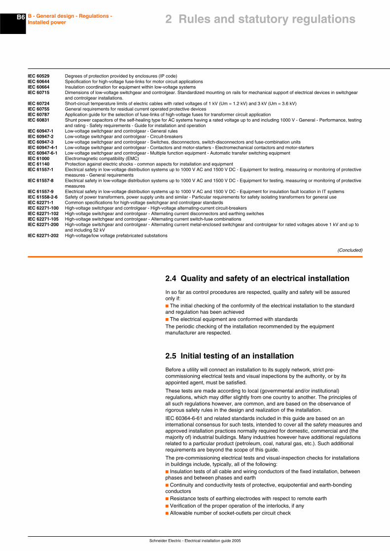
IEC 60529 Degrees of protection provided by enclosures (IP code)IEC 60644 Spécification for high-voltage fuse-links for motor circuit applicationsIEC 60664 Insulation coordination for equipment within low-voltage systemsIEC 60715 Dimensions of low-voltage switchgear and controlgear. Standardized mounting on rails for mechanical support of electrical devices in switchgear
and controlgear installations.IEC 60724 Short-circuit temperature limits of electric cables with rated voltages of 1 kV (Um = 1.2 kV) and 3 kV (Um = 3.6 kV)IEC 60755 General requirements for residual current operated protective devicesIEC 60787 Application guide for the selection of fuse-links of high-voltage fuses for transformer circuit applicationIEC 60831 Shunt power capacitors of the self-healing type for AC systems having a rated voltage up to and including 1000 V - General - Performance, testing
and rating - Safety requirements - Guide for installation and operationIEC 60947-1 Low-voltage switchgear and controlgear - General rulesIEC 60947-2 Low-voltage switchgear and controlgear - Circuit-breakersIEC 60947-3 Low-voltage switchgear and controlgear - Switches, disconnectors, switch-disconnectors and fuse-combination unitsIEC 60947-4-1 Low-voltage switchgear and controlgear - Contactors and motor-starters - Electromechanical contactors and motor-startersIEC 60947-6-1 Low-voltage switchgear and controlgear - Multiple function equipment - Automatic transfer switching equipmentIEC 61000 Electromagnetic compatibility (EMC)IEC 61140 Protection against electric shocks - common aspects for installation and equipmentIEC 61557-1 Electrical safety in low-voltage distribution systems up to 1000 V AC and 1500 V DC - Equipment for testing, measuring or monitoring of protective
measures - General requirementsIEC 61557-8 Electrical safety in low-voltage distribution systems up to 1000 V AC and 1500 V DC - Equipment for testing, measuring or monitoring of protective
measuresIEC 61557-9 Electrical safety in low-voltage distribution systems up to 1000 V AC and 1500 V DC - Equipment for insulation fault location in IT systemsIEC 61558-2-6 Safety of power transformers, power supply units and similar - Particular requirements for safety isolating transformers for general useIEC 62271-1 Common specifications for high-voltage switchgear and controlgear standardsIEC 62271-100 High-voltage switchgear and controlgear - High-voltage alternating-current circuit-breakersIEC 62271-102 High-voltage switchgear and controlgear - Alternating current disconnectors and earthing switchesIEC 62271-105 High-voltage switchgear and controlgear - Alternating current switch-fuse combinationsIEC 62271-200 High-voltage switchgear and controlgear - Alternating current metal-enclosed switchgear and controlgear for rated voltages above 1 kV and up to
and including 52 kVIEC 62271-202 High-voltage/low voltage prefabricated substations
(Concluded)
2.4 Quality and safety of an electrical installation
In so far as control procedures are respected, quality and safety will be assuredonly if:c The initial checking of the conformity of the electrical installation to the standardand regulation has been achievedc The electrical equipment are conformed with standardsThe periodic checking of the installation recommended by the equipmentmanufacturer are respected.
2.5 Initial testing of an installation
Before a utility will connect an installation to its supply network, strict pre-commissioning electrical tests and visual inspections by the authority, or by itsappointed agent, must be satisfied.
These tests are made according to local (governmental and/or institutional)regulations, which may differ slightly from one country to another. The principles ofall such regulations however, are common, and are based on the observance ofrigorous safety rules in the design and realization of the installation.
IEC 60364-6-61 and related standards included in this guide are based on aninternational consensus for such tests, intended to cover all the safety measures andapproved installation practices normally required for domestic, commercial and (themajority of) industrial buildings. Many industries however have additional regulationsrelated to a particular product (petroleum, coal, natural gas, etc.). Such additionalrequirements are beyond the scope of this guide.
The pre-commissioning electrical tests and visual-inspection checks for installationsin buildings include, typically, all of the following:c Insulation tests of all cable and wiring conductors of the fixed installation, betweenphases and between phases and earthc Continuity and conductivity tests of protective, equipotential and earth-bondingconductorsc Resistance tests of earthing electrodes with respect to remote earthc Verification of the proper operation of the interlocks, if anyc Allowable number of socket-outlets per circuit check
2 Rules and statutory regulations
B7
Schneider Electric - Electrical installation guide 2005
B - General design - Regulations -Installed power 2 Rules and statutory regulations
c Cross-sectional-area check of all conductors for adequacy at the short-circuitlevels prevailing, taking account of the associated protective devices, materials andinstallation conditions (in air, conduit, etc.)c Verification that all exposed- and extraneous metallic parts are properly earthed(where appropriate)c Check of clearance distances in bathrooms, etc.
These tests and checks are basic (but not exhaustive) to the majority of installations,while numerous other tests and rules are included in the regulations to coverparticular cases, for example: TN-, TT- or IT-earthed installations, installations basedon class 2 insulation, SELV circuits, and special locations, etc.
The aim of this guide is to draw attention to the particular features of different typesof installation, and to indicate the essential rules to be observed in order to achieve asatisfactory level of quality, which will ensure safe and trouble-free performance. Themethods recommended in this guide, modified if necessary to comply with anypossible variation imposed by a utility, are intended to satisfy all precommissioningtest and inspection requirements.
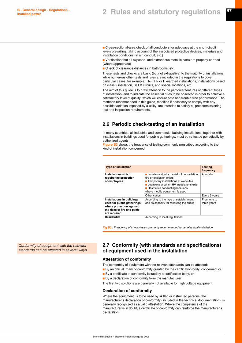
2.6 Periodic check-testing of an installation
In many countries, all industrial and commercial-building installations, together withinstallations in buildings used for public gatherings, must be re-tested periodically byauthorized agents.Figure B3 shows the frequency of testing commonly prescribed according to thekind of installation concerned.
Fig B3 : Frequency of check-tests commonly recommended for an electrical installation
2.7 Conformity (with standards and specifications)of equipment used in the installation
Attestation of conformityThe conformity of equipment with the relevant standards can be attested:c By an official mark of conformity granted by the certification body concerned, orc By a certificate of conformity issued by a certification body, orc By a declaration of conformity from the manufacturer
The first two solutions are generally not available for high voltage equipment.
Declaration of conformityWhere the equipment is to be used by skilled or instructed persons, themanufacturer’s declaration of conformity (included in the technical documentation), isgenerally recognized as a valid attestation. Where the competence of themanufacturer is in doubt, a certificate of conformity can reinforce the manufacturer’sdeclaration.
Type of installation Testingfrequency
Installations which c Locations at which a risk of degradation, Annuallyrequire the protection fire or explosion existsof employees c Temporary installations at worksites
c Locations at which HV installations existc Restrictive conducting locationswhere mobile equipment is usedOther cases Every 3 years
Installations in buildings According to the type of establishment From one toused for public gatherings, and its capacity for receiving the public three yearswhere protection againstthe risks of fire and panicare requiredResidential According to local regulations
Conformity of equipment with the relevantstandards can be attested in several ways
Schneider Electric - Electrical installation guide 2005
B8 B - General design - Regulations -Installed power
Note: CE markingIn Europe, the European directives require the manufacturer or his authorizedrepresentative to affix the CE marking on his own responsibility. It means that:c The product meets the legal requirementsc It is presumed to be marketable in EuropeThe CE marking is neither a mark of origin nor a mark of conformity.
Mark of conformityMarks of conformity are affixed on appliances and equipment generally used byordinary non instructed persons (e.g in the field of domestic appliances). A mark ofconformity is delivered by certification body if the equipment meet the requirementsfrom an applicable standard and after verification of the manufacture’s qualitymanagement system.
Certification of QualityThe standards define several methods of quality assurance which correspond todifferent situations rather than to different levels of quality.
AssuranceA laboratory for testing samples cannot certify the conformity of an entire productionrun:These tests are called type tests. In some tests for conformity to standards,the samples are destroyed (tests on fuses, for example).Only the manufacturer can certify that the fabricated products have, in fact,the characteristics stated.Quality assurance certification is intended to complete the initial declaration orcertification of conformity.As proof that all the necessary measures have been taken for assuring the quality ofproduction, the manufacturer obtains certification of the quality control system whichmonitors the fabrication of the product concerned. These certificates are issued byorganizations specializing in quality control, and are based on the internationalstandard ISO 9000.
These standards define three model systems of quality assurance controlcorresponding to different situations rather than to different levels of quality:
c Model 3 defines assurance of quality by inspection and checking of final products.
c Model 2 includes, in addition to checking of the final product, verification of themanufacturing process. For example, this method is applied, to the manufacturer offuses where performance characteristics cannot be checked without destroying thefuse.
c Model 1 corresponds to model 2, but with the additional requirement that thequality of the design process must be rigorously scrutinized; for example, where it isnot intended to fabricate and test a prototype (case of a custom-built product made tospecification).
2.8 Environment
Environmental management systems can be certified by an independent body if theymeet requirements given in ISO 14001. This type of certification mainly concernsindustrial settings but can also be granted to places where products are designed.
A product environmental design sometimes called “eco-design” is an approach ofsustainable development with the objective of designing products/services bestmeeting the customers’ requirements while reducing their environmental impact overtheir whole life cycle. The methodologies used for this purpose lead to chooseequipment’s architecture together with components and materials taking into accountthe influence of a product on the environment along its life cycle (from extraction ofraw materials to grave) i.e. production, transport, distribution, end of life etc.
In Europe two Directives have been published, they are called:c RoHS Directive (Restriction of Hazardous Substances) coming into force on July2006 (the coming into force was on February 13th, 2003, and the application date isJuly 1st, 2006) aims to eliminate from products six hazardous substances: lead,mercury, cadmium, hexavalent chromium, polybrominated biphenyls (PBB) orpolybrominated diphenyl ethers (PBDE).
2 Rules and statutory regulations
B9
Schneider Electric - Electrical installation guide 2005
B - General design - Regulations -Installed power 2 Rules and statutory regulations
c WEEE Directive (Waste of Electrical and Electronic Equipment) coming into forcein August 2005 2006 (the coming into force was on February 13th, 2003, and theapplication date is August 13th, 2005) in order to master the end of life andtreatments for household and non household equipment.
In other part of the world some new legislation will follow the same objectives.
In addition to manufacturers action in favour of products eco-design, the contributionof the whole electrical installation to sustainable development can be significantlyimproved through the design of the installation. Actually, it has been shown that anoptimised conception of the installation, taking into account operation conditions,MV/LV substations location and distribution structure (switchboards, busways,cables), can lead to a reduce substancially environmental impacts (raw materialdepletion, energy depletion, end of life)See chapter E about location of the substation and the main LV switchboard.
Schneider Electric - Electrical installation guide 2005
B10 B - General design - Regulations -Installed power 3 Installed power loads -
Characteristics
The examination of actual values of apparent-power required by each load enablesthe establishment of:
c A declared power demand which determines the contract for the supply of energy
c The rating of the HV/LV transformer, where applicable (allowing for expectedincreases load)
c Levels of load current at each distribution board
3.1 Induction motors
Current demandThe full-load current Ia supplied to the motor is given by the following formulae:
c 3-phase motor: Ia = Pn x 1,000 / √3 x U x η x cos ϕ
c 1-phase motor: Ia = Pn x 1,000 / U x η x cos ϕ
where
Ia: current demand (in amps)Pn: nominal power (in kW of active power)U: voltage between phases for 3-phase motors and voltage between the terminalsfor single-phase motors (in volts). A single-phase motor may be connected phase-to-neutral or phase-to-phase.
η: per-unit efficiency, i.e. output kW / input kW
cos ϕ: power factor, i.e. kW input / kVA input
Subtransient current and protection settingc Subtransient current peak value can be very high ; typical value is about 12to 15 times the RMS rated value Inm. Sometimes this value can reach 25 times Inm.
c Merlin Gerin circuit breakers, Telemecanique contactors and thermal relays aredesigned to withstand motor starts with very high subtransient current (subtransientpeak value can be up to 19 RMS rated value Inm).
c If unexpected tripping of the overcurrent protection occurs during starting, thismeans the starting current exceeds the normal limits. As a result, some maximumswitchgears withstands can be reach, life time can be reduce and even somedevices can be destroyed. In order to avoid such a situation, oversizing of theswitchgear must be considered.
c Merlin Gerin and Telemecanique switchgears are designed to ensure theprotection of motor starters against short circuits. According to the risk, tables showthe combination of circuit breaker, contactor and thermal relay to obtain type 1 ortype 2 coordination (see chapter M).
Motor starting currentAlthough high efficiency motors can be find on the market, in practice their startingcurrents are roughly the same as some of standard motors.
The use of start-delta starter, static soft start unit or speed drive converter allows toreduce the value of the starting current (Example : 4 Ia instead of 7.5 Ia).
Compensation of reactive-power (kvar) supplied to induction motorsIt is generally advantageous for technical and financial reasons to reduce the currentsupplied to induction motors. This can be achieved by using capacitors withoutaffecting the power output of the motors.The application of this principle to the operation of induction motors is generallyreferred to as “power-factor improvement” or “power-factor correction”.
As discussed in chapter K, the apparent power (kVA) supplied to an induction motorcan be significantly reduced by the use of shunt-connected capacitors. Reduction ofinput kVA means a corresponding reduction of input current (since the voltageremains constant).
Compensation of reactive-power is particularly advised for motors that operate forlong periods at reduced power.
As noted above cos = kW inputkVA input
ϕ so that a kVA input reduction in kVA input will
increase (i.e. improve) the value of cos ϕ.
An examination of the actual apparent-powerdemands of different loads: a necessarypreliminary step in the design of aLV installation
The nominal power in kW (Pn) of a motorindicates its rated equivalent mechanical poweroutput.The apparent power in kVA (Pa) supplied to themotor is a function of the output, the motorefficiency and the power factor.Pa = Pn / η cos ϕ
B11
Schneider Electric - Electrical installation guide 2005
B - General design - Regulations -Installed power
The current supplied to the motor, after power-factor correction, is given by:
Ia cos cos '
=ϕ
ϕ
where cos ϕ is the power factor before compensation and cos ϕ’ is the power factorafter compensation, Ia being the original current.
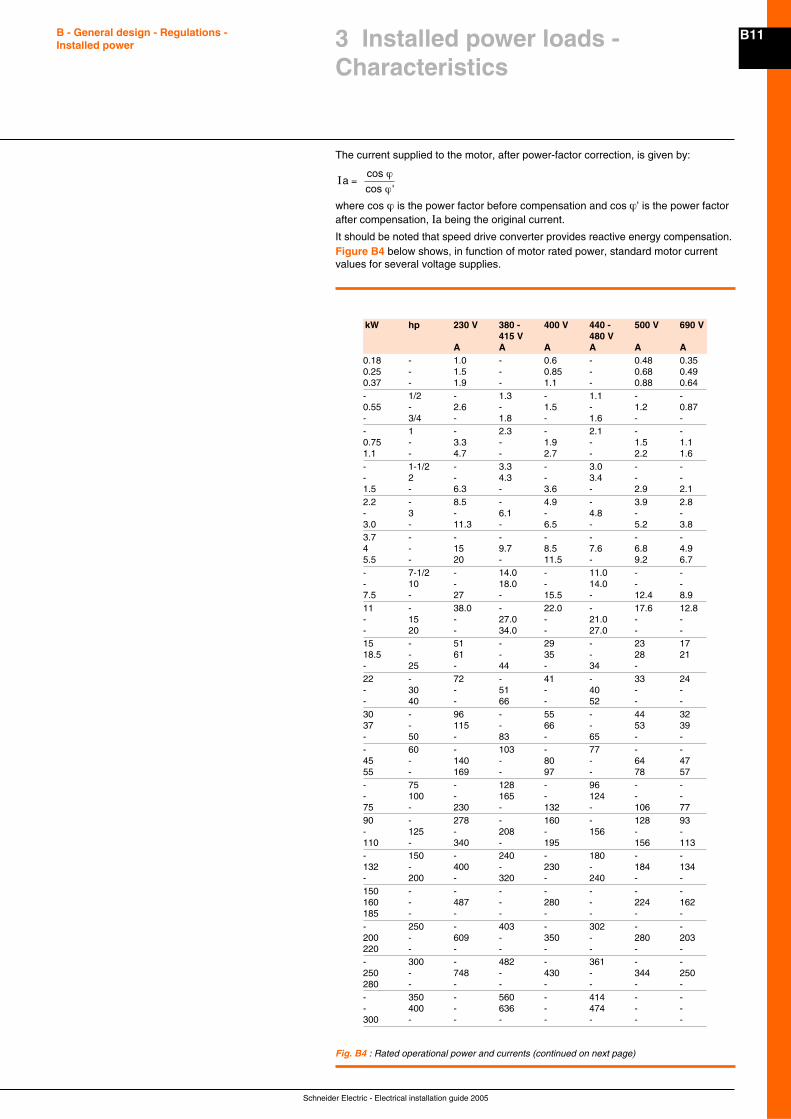
It should be noted that speed drive converter provides reactive energy compensation.Figure B4 below shows, in function of motor rated power, standard motor currentvalues for several voltage supplies.
3 Installed power loads -Characteristics
kW hp 230 V 380 - 400 V 440 - 500 V 690 V415 V 480 V
A A A A A A0.18 - 1.0 - 0.6 - 0.48 0.350.25 - 1.5 - 0.85 - 0.68 0.490.37 - 1.9 - 1.1 - 0.88 0.64- 1/2 - 1.3 - 1.1 - -0.55 - 2.6 - 1.5 - 1.2 0.87- 3/4 - 1.8 - 1.6 - -- 1 - 2.3 - 2.1 - -0.75 - 3.3 - 1.9 - 1.5 1.11.1 - 4.7 - 2.7 - 2.2 1.6- 1-1/2 - 3.3 - 3.0 - -- 2 - 4.3 - 3.4 - -1.5 - 6.3 - 3.6 - 2.9 2.12.2 - 8.5 - 4.9 - 3.9 2.8- 3 - 6.1 - 4.8 - -3.0 - 11.3 - 6.5 - 5.2 3.83.7 - - - - - - -4 - 15 9.7 8.5 7.6 6.8 4.95.5 - 20 - 11.5 - 9.2 6.7- 7-1/2 - 14.0 - 11.0 - -- 10 - 18.0 - 14.0 - -7.5 - 27 - 15.5 - 12.4 8.911 - 38.0 - 22.0 - 17.6 12.8- 15 - 27.0 - 21.0 - -- 20 - 34.0 - 27.0 - -15 - 51 - 29 - 23 1718.5 - 61 - 35 - 28 21- 25 - 44 - 34 -22 - 72 - 41 - 33 24- 30 - 51 - 40 - -- 40 - 66 - 52 - -30 - 96 - 55 - 44 3237 - 115 - 66 - 53 39- 50 - 83 - 65 - -- 60 - 103 - 77 - -45 - 140 - 80 - 64 4755 - 169 - 97 - 78 57- 75 - 128 - 96 - -- 100 - 165 - 124 - -75 - 230 - 132 - 106 7790 - 278 - 160 - 128 93- 125 - 208 - 156 - -110 - 340 - 195 156 113- 150 - 240 - 180 - -132 - 400 - 230 - 184 134- 200 - 320 - 240 - -150 - - - - - - -160 - 487 - 280 - 224 162185 - - - - - - -- 250 - 403 - 302 - -200 - 609 - 350 - 280 203220 - - - - - - -- 300 - 482 - 361 - -250 - 748 - 430 - 344 250280 - - - - - - -- 350 - 560 - 414 - -- 400 - 636 - 474 - -300 - - - - - - -
Fig. B4 : Rated operational power and currents (continued on next page)
Schneider Electric - Electrical installation guide 2005
B12 B - General design - Regulations -Installed power
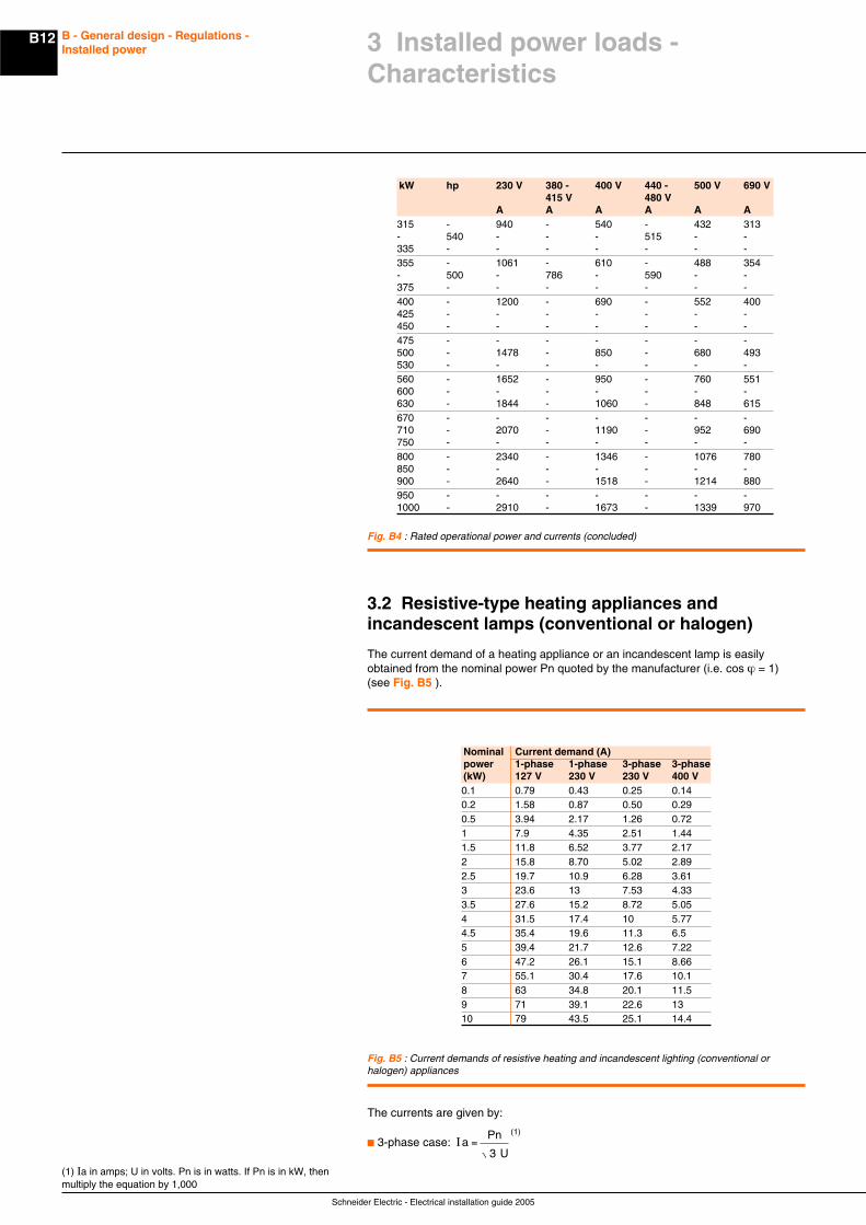
kW hp 230 V 380 - 400 V 440 - 500 V 690 V415 V 480 V
A A A A A A315 - 940 - 540 - 432 313- 540 - - - 515 - -335 - - - - - - -355 - 1061 - 610 - 488 354- 500 - 786 - 590 - -375 - - - - - - -400 - 1200 - 690 - 552 400425 - - - - - - -450 - - - - - - -475 - - - - - - -500 - 1478 - 850 - 680 493530 - - - - - - -560 - 1652 - 950 - 760 551600 - - - - - - -630 - 1844 - 1060 - 848 615670 - - - - - - -710 - 2070 - 1190 - 952 690750 - - - - - - -800 - 2340 - 1346 - 1076 780850 - - - - - - -900 - 2640 - 1518 - 1214 880950 - - - - - - -1000 - 2910 - 1673 - 1339 970
Fig. B4 : Rated operational power and currents (concluded)
3.2 Resistive-type heating appliances andincandescent lamps (conventional or halogen)
The current demand of a heating appliance or an incandescent lamp is easilyobtained from the nominal power Pn quoted by the manufacturer (i.e. cos ϕ = 1)(see Fig. B5 ).
The currents are given by:
c 3-phase case: Ia
=Pn
U3
(1)
(1) Ia in amps; U in volts. Pn is in watts. If Pn is in kW, thenmultiply the equation by 1,000
Fig. B5 : Current demands of resistive heating and incandescent lighting (conventional orhalogen) appliances
Nominal Current demand (A)power 1-phase 1-phase 3-phase 3-phase(kW) 127 V 230 V 230 V 400 V0.1 0.79 0.43 0.25 0.140.2 1.58 0.87 0.50 0.290.5 3.94 2.17 1.26 0.721 7.9 4.35 2.51 1.441.5 11.8 6.52 3.77 2.172 15.8 8.70 5.02 2.892.5 19.7 10.9 6.28 3.613 23.6 13 7.53 4.333.5 27.6 15.2 8.72 5.054 31.5 17.4 10 5.774.5 35.4 19.6 11.3 6.55 39.4 21.7 12.6 7.226 47.2 26.1 15.1 8.667 55.1 30.4 17.6 10.18 63 34.8 20.1 11.59 71 39.1 22.6 1310 79 43.5 25.1 14.4
3 Installed power loads -Characteristics
B13
Schneider Electric - Electrical installation guide 2005
B - General design - Regulations -Installed power 3 Installed power loads -
Characteristics
(1) “Power-factor correction” is often referred to as“compensation” in discharge-lighting-tube terminology.Cos ϕ is approximately 0.95 (the zero values of V and I arealmost in phase) but the power factor is 0.5 due to theimpulsive form of the current, the peak of which occurs “late”in each half cycle
Fig. B6 : Current demands and power consumption of commonly-dimensioned fluorescentlighting tubes (at 230 V-50 Hz)
c 1-phase case: Ia =PnU
(1)
where U is the voltage between the terminals of the equipment.
The current demand of a heating appliance or an incandescent lamp is easilyobtained from the nominal power Pn quoted by the manufacturer (i.e. cos ϕ = 1).
The currents are given by:
c 3-phase case: Ia
=Pn
U3
(1)
c 1-phase case: Ia =PnU
(1)
where U is the voltage between the terminals of the equipment.
For an incandescent lamp, the use of halogen gas allows a more concentrated lightsource. The light output is increased and the lifetime of the lamp is doubled.
Note: At the instant of switching on, the cold filament gives rise to a very brief butintense peak of current.
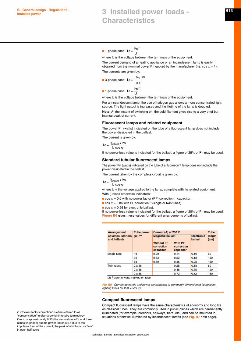
Fluorescent lamps and related equipmentThe power Pn (watts) indicated on the tube of a fluorescent lamp does not includethe power dissipated in the ballast.
The current is given by:
Ia cos
=+P Pn
Uballast
ϕIf no power-loss value is indicated for the ballast, a figure of 25% of Pn may be used.
Standard tubular fluorescent lampsThe power Pn (watts) indicated on the tube of a fluorescent lamp does not include thepower dissipated in the ballast.
The current taken by the complete circuit is given by:
Ia cos
=+P Pn
Uballast
ϕwhere U = the voltage applied to the lamp, complete with its related equipment.With (unless otherwise indicated):c cos ϕ = 0.6 with no power factor (PF) correction(1) capacitorc cos ϕ = 0.86 with PF correction(1) (single or twin tubes)c cos ϕ = 0.96 for electronic ballast.If no power-loss value is indicated for the ballast, a figure of 25% of Pn may be used.Figure B6 gives these values for different arrangements of ballast.
Arrangement Tube power Current (A) at 230 V Tubeof lamps, starters (W) (2) Magnetic ballast Electronic lengthand ballasts ballast (cm)
Without PF With PFcorrection correctioncapacitor capacitor
Single tube 18 0.20 0.14 0.10 6036 0.33 0.23 0.18 12058 0.50 0.36 0.28 150
Twin tubes 2 x 18 0.28 0.18 602 x 36 0.46 0.35 1202 x 58 0.72 0.52 150
(2) Power in watts marked on tube
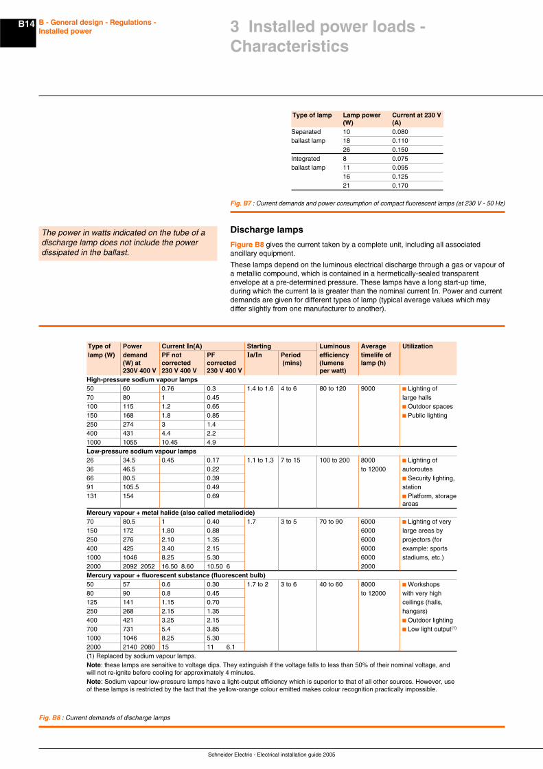
Compact fluorescent lampsCompact fluorescent lamps have the same characteristics of economy and long lifeas classical tubes. They are commonly used in public places which are permanentlyilluminated (for example: corridors, hallways, bars, etc.) and can be mounted insituations otherwise illuminated by incandescent lamps (see Fig. B7 next page).
Schneider Electric - Electrical installation guide 2005
B14 B - General design - Regulations -Installed power 3 Installed power loads -
Characteristics
The power in watts indicated on the tube of adischarge lamp does not include the powerdissipated in the ballast.
Discharge lamps
Figure B8 gives the current taken by a complete unit, including all associatedancillary equipment.
These lamps depend on the luminous electrical discharge through a gas or vapour ofa metallic compound, which is contained in a hermetically-sealed transparentenvelope at a pre-determined pressure. These lamps have a long start-up time,during which the current Ia is greater than the nominal current In. Power and currentdemands are given for different types of lamp (typical average values which maydiffer slightly from one manufacturer to another).
Fig. B7 : Current demands and power consumption of compact fluorescent lamps (at 230 V - 50 Hz)
Type of lamp Lamp power Current at 230 V(W) (A)
Separated 10 0.080ballast lamp 18 0.110
26 0.150Integrated 8 0.075ballast lamp 11 0.095
16 0.12521 0.170
Fig. B8 : Current demands of discharge lamps
Type of Power Current In(A) Starting Luminous Average Utilizationlamp (W) demand PF not PF Ia/In Period efficiency timelife of
(W) at corrected corrected (mins) (lumens lamp (h)230V 400 V 230 V 400 V 230 V 400 V per watt)
High-pressure sodium vapour lamps50 60 0.76 0.3 1.4 to 1.6 4 to 6 80 to 120 9000 c Lighting of70 80 1 0.45 large halls100 115 1.2 0.65 c Outdoor spaces150 168 1.8 0.85 c Public lighting250 274 3 1.4400 431 4.4 2.21000 1055 10.45 4.9Low-pressure sodium vapour lamps26 34.5 0.45 0.17 1.1 to 1.3 7 to 15 100 to 200 8000 c Lighting of36 46.5 0.22 to 12000 autoroutes66 80.5 0.39 c Security lighting,91 105.5 0.49 station131 154 0.69 c Platform, storage
areasMercury vapour + metal halide (also called metaliodide)70 80.5 1 0.40 1.7 3 to 5 70 to 90 6000 c Lighting of very150 172 1.80 0.88 6000 large areas by250 276 2.10 1.35 6000 projectors (for400 425 3.40 2.15 6000 example: sports1000 1046 8.25 5.30 6000 stadiums, etc.)2000 2092 2052 16.50 8.60 10.50 6 2000Mercury vapour + fluorescent substance (fluorescent bulb)50 57 0.6 0.30 1.7 to 2 3 to 6 40 to 60 8000 c Workshops80 90 0.8 0.45 to 12000 with very high125 141 1.15 0.70 ceilings (halls,250 268 2.15 1.35 hangars)400 421 3.25 2.15 c Outdoor lighting700 731 5.4 3.85 c Low light output(1)
1000 1046 8.25 5.302000 2140 2080 15 11 6.1(1) Replaced by sodium vapour lamps.Note: these lamps are sensitive to voltage dips. They extinguish if the voltage falls to less than 50% of their nominal voltage, andwill not re-ignite before cooling for approximately 4 minutes.Note: Sodium vapour low-pressure lamps have a light-output efficiency which is superior to that of all other sources. However, useof these lamps is restricted by the fact that the yellow-orange colour emitted makes colour recognition practically impossible.
B15
Schneider Electric - Electrical installation guide 2005
B - General design - Regulations -Installed power
In order to design an installation, the actual maximum load demand likely to beimposed on the power-supply system must be assessed.
To base the design simply on the arithmetic sum of all the loads existing in theinstallation would be extravagantly uneconomical, and bad engineering practice.
The aim of this chapter is to show how some factors taking into account the diversity(nonsimultaneous operation of all appliances of a given group) and utilization (e.g.an electric motor is not generally operated at its full-load capability, etc.) of allexisting and projected loads can be assessed. The values given are based onexperience and on records taken from actual installations. In addition to providingbasic installation-design data on individual circuits, the results will provide a globalvalue for the installation, from which the requirements of a supply system(distribution network, HV/LV transformer, or generating set) can be specified.
4.1 Installed power (kW)
The installed power is the sum of the nominalpowers of all powerconsuming devices in theinstallation.This is not the power to be actually supplied inpractice.
Most electrical appliances and equipments are marked to indicate their nominalpower rating (Pn).The installed power is the sum of the nominal powers of all power-consumingdevices in the installation. This is not the power to be actually supplied in practice.This is the case for electric motors, where the power rating refers to the outputpower at its driving shaft. The input power consumption will evidently be greater
Fluorescent and discharge lamps associated with stabilizing ballasts, are othercases in which the nominal power indicated on the lamp is less than the powerconsumed by the lamp and its ballast.
Methods of assessing the actual power consumption of motors and lightingappliances are given in Section 3 of this Chapter.
The power demand (kW) is necessary to choose the rated power of a generating setor battery, and where the requirements of a prime mover have to be considered.
For a power supply from a LV public-supply network, or through a HV/LV transformer,the significant quantity is the apparent power in kVA.
4.2 Installed apparent power (kVA)
The installed apparent power is commonly assumed to be the arithmetical sum ofthe kVA of individual loads. The maximum estimated kVA to be supplied however isnot equal to the total installed kVA.
The apparent-power demand of a load (which might be a single appliance) isobtained from its nominal power rating (corrected if necessary, as noted above formotors, etc.) and the application of the following coefficients:
η = the per-unit efficiency = output kW / input kWcos ϕ = the power factor = kW / kVA
The apparent-power kVA demand of the loadPa = Pn /(η x cos ϕ)
From this value, the full-load current Ia (A)(1) taken by the load will be:
c Ia =Pa x 10
V
3
for single phase-to-neutral connected load
c Ia =Pa x 10
3 x U
3
for three-phase balanced load where:V = phase-to-neutral voltage (volts)U = phase-to-phase voltage (volts)It may be noted that, strictly speaking, the total kVA of apparent power is not thearithmetical sum of the calculated kVA ratings of individual loads (unless all loadsare at the same power factor).It is common practice however, to make a simple arithmetical summation, the resultof which will give a kVA value that exceeds the true value by an acceptable “designmargin”.When some or all of the load characteristics are not known, the values shown inFigure B9 next page may be used to give a very approximate estimate of VAdemands (individual loads are generally too small to be expressed in kVA or kW).The estimates for lighting loads are based on floor areas of 500 m2.
The installed apparent power is commonlyassumed to be the arithmetical sum of the kVAof individual loads. The maximum estimatedkVA to be supplied however is not equal to thetotal installed kVA.
(1) For greater precision, account must be taken of the factorof maximum utilization as explained below in 4.3
4 Power loading of an installation

Schneider Electric - Electrical installation guide 2005
B16 B - General design - Regulations -Installed power
Fig. B9 : Estimation of installed apparent power
4.3 Estimation of actual maximum kVA demand
All individual loads are not necessarily operating at full rated nominal power nornecessarily at the same time. Factors ku and ks allow the determination of themaximum power and apparent-power demands actually required to dimension theinstallation.
Factor of maximum utilization (ku)In normal operating conditions the power consumption of a load is sometimes lessthan that indicated as its nominal power rating, a fairly common occurrence thatjustifies the application of an utilization factor (ku) in the estimation of realisticvalues.This factor must be applied to each individual load, with particular attention toelectric motors, which are very rarely operated at full load.In an industrial installation this factor may be estimated on an average at 0.75 formotors.For incandescent-lighting loads, the factor always equals 1.For socket-outlet circuits, the factors depend entirely on the type of appliances beingsupplied from the sockets concerned.
Factor of simultaneity (ks)It is a matter of common experience that the simultaneous operation of all installedloads of a given installation never occurs in practice, i.e. there is always somedegree of diversity and this fact is taken into account for estimating purposes by theuse of a simultaneity factor (ks).The factor ks is applied to each group of loads (e.g. being supplied from adistribution or sub-distribution board). The determination of these factors is theresponsibility of the designer, since it requires a detailed knowledge of theinstallation and the conditions in which the individual circuits are to be exploited.For this reason, it is not possible to give precise values for general application.
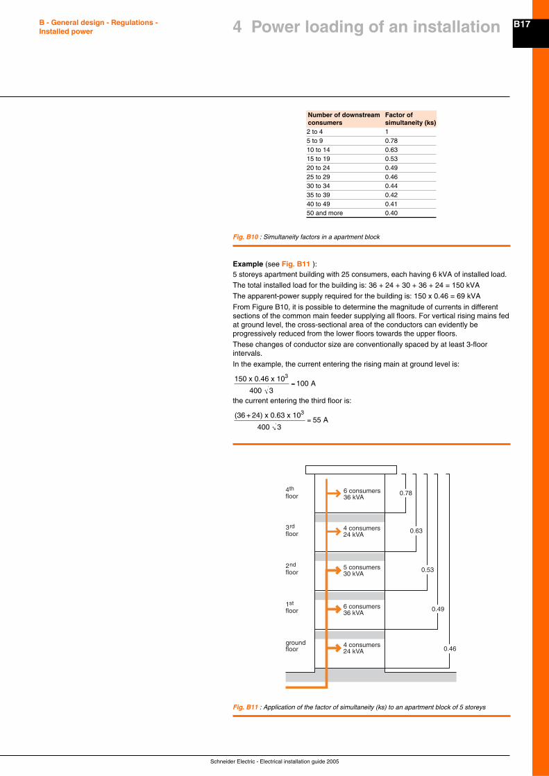
Factor of simultaneity for an apartment blockSome typical values for this case are given in Figure B10 opposite page, and areapplicable to domestic consumers supplied at 230/400 V (3-phase 4-wires). In thecase of consumers using electrical heat-storage units for space heating, a factor of0.8 is recommended, regardless of the number of consumers.
Fluorescent lighting (corrected to cos ϕ = 0.86)Type of application Estimated (VA/m2) Average lighting
fluorescent tube level (lux = lm/m2)with industrial reflector(1)
Roads and highways 7 150stockage areas, intermittent workHeavy-duty works: fabrication and 14 300assembly of very large work piecesDay-to-day work: office work 24 500Fine work: drawing offices 41 800high-precision assembly workshopsPower circuitsType of application Estimated (VA/m2)Pumping station compressed air 3 to 6Ventilation of premises 23Electrical convection heaters: 115 to 146private houses flats and apartments 90Offices 25Dispatching workshop 50Assembly workshop 70Machine shop 300Painting workshop 350Heat-treatment plant 700(1) example: 65 W tube (ballast not included), flux 5,100 lumens (Im),luminous efficiency of the tube = 78.5 Im / W.
4 Power loading of an installation
B17
Schneider Electric - Electrical installation guide 2005
B - General design - Regulations -Installed power
Example (see Fig. B11 ):5 storeys apartment building with 25 consumers, each having 6 kVA of installed load.
The total installed load for the building is: 36 + 24 + 30 + 36 + 24 = 150 kVA
The apparent-power supply required for the building is: 150 x 0.46 = 69 kVA
From Figure B10, it is possible to determine the magnitude of currents in differentsections of the common main feeder supplying all floors. For vertical rising mains fedat ground level, the cross-sectional area of the conductors can evidently beprogressively reduced from the lower floors towards the upper floors.
These changes of conductor size are conventionally spaced by at least 3-floorintervals.
In the example, the current entering the rising main at ground level is:
150 x 0.46 x 10
400 3
3=100 A
the current entering the third floor is:
(36 + 24) x 0.63 x 10
400 3
3= 55 A
4thfloor
6 consumers36 kVA
3rdfloor
2ndfloor
1stfloor
groundfloor
4 consumers24 kVA
6 consumers36 kVA
5 consumers30 kVA
4 consumers24 kVA
0.78
0.63
0.53
0.49
0.46
Fig. B11 : Application of the factor of simultaneity (ks) to an apartment block of 5 storeys
4 Power loading of an installation
Fig. B10 : Simultaneity factors in a apartment block
Number of downstream Factor ofconsumers simultaneity (ks)2 to 4 15 to 9 0.7810 to 14 0.6315 to 19 0.5320 to 24 0.4925 to 29 0.4630 to 34 0.4435 to 39 0.4240 to 49 0.4150 and more 0.40
Schneider Electric - Electrical installation guide 2005
B18 B - General design - Regulations -Installed power
4.4 Example of application of factors ku and ks
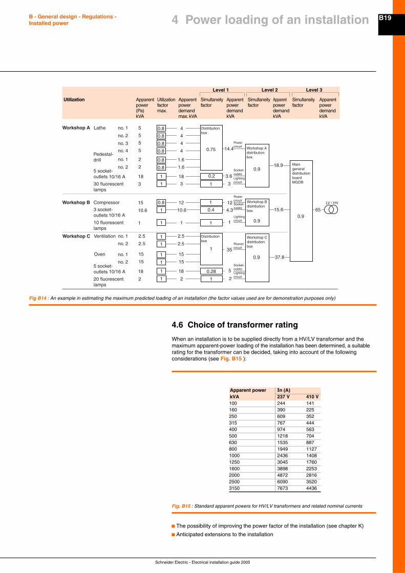
An example in the estimation of actual maximum kVA demands at all levels of aninstallation, from each load position to the point of supply (see Fig. B14 oppositepage).
In this example, the total installed apparent power is 126.6 kVA, which correspondsto an actual (estimated) maximum value at the LV terminals of the HV/LV transformerof 65 kVA only.
Note: in order to select cable sizes for the distribution circuits of an installation, thecurrent I (in amps) through a circuit is determined from the equation:
I =kVA
U
x 10
3
3
where kVA is the actual maximum 3-phase apparent-power value shown on thediagram for the circuit concerned, and U is the phaseto- phase voltage (in volts).
4.5 Diversity factor
The term diversity factor, as defined in IEC standards, is identical to the factor ofsimultaneity (ks) used in this guide, as described in 4.3. In some English-speakingcountries however (at the time of writing) diversity factor is the inverse of ks i.e. it isalways u 1.
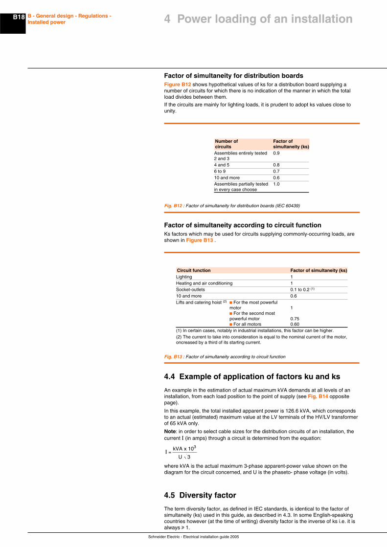
Factor of simultaneity for distribution boardsFigure B12 shows hypothetical values of ks for a distribution board supplying anumber of circuits for which there is no indication of the manner in which the totalload divides between them.
If the circuits are mainly for lighting loads, it is prudent to adopt ks values close tounity.
Fig. B12 : Factor of simultaneity for distribution boards (IEC 60439)
Number of Factor ofcircuits simultaneity (ks)Assemblies entirely tested 0.92 and 34 and 5 0.86 to 9 0.710 and more 0.6Assemblies partially tested 1.0in every case choose
Factor of simultaneity according to circuit functionKs factors which may be used for circuits supplying commonly-occurring loads, areshown in Figure B13 .
Circuit function Factor of simultaneity (ks)Lighting 1Heating and air conditioning 1Socket-outlets 0.1 to 0.2 (1)
10 and more 0.6Lifts and catering hoist (2)
c For the most powerfulmotor 1c For the second mostpowerful motor 0.75c For all motors 0.60
(1) In certain cases, notably in industrial installations, this factor can be higher.(2) The current to take into consideration is equal to the nominal current of the motor,oncreased by a third of its starting current.
Fig. B13 : Factor of simultaneity according to circuit function
4 Power loading of an installation
B19
Schneider Electric - Electrical installation guide 2005
B - General design - Regulations -Installed power 4 Power loading of an installation
Fig B14 : An example in estimating the maximum predicted loading of an installation (the factor values used are for demonstration purposes only)
1
Distributionbox
Workshop A 5 0.8
0.8
0.8
0.8
0.8
0.8
5
5
5
2
2
Lathe
18
3 11
10.8
0.41
15
10.6
2.5
2.5
15
15
Ventilation
0.28118
112
1Oven
30 fluorescentlamps
Pedestal-drill
Workshop B Compressor
Workshop C
no. 1
no. 2
no. 3
no. 4
no. 1
no. 2
no. 1
no. 2
no. 1
no. 2
4
4
4
4
1.6
1.6
18
3
14.4
12
1
1
1
1
2.5
2
18
15
15
2.5
Workshop Adistributionbox
0.75
Powercircuit
Powercircuit
Powvercircuit
Workshop Bdistributionbox
Workshop Cdistributionbox
MaingeneraldistributionboardMGDB
Socket-oulets
Socket-oulets
Socket-oulets
Lightingcircuit
Lightingcircuit
Lightingcircuit
0.9
0.9
0.9
0.910.6
3.6
3
12
4.3
1
15.6
18.9
37.8
35
5
2
65
LV / HV
Distributionbox
111
0.21
10/16 A
5 socket-outlets
20 fluorescentlamps
5 socket-outlets
10 fluorescentlamps
3 socket-outlets
10/16 A
10/16 A
Utilization Apparent Utilization Apparent Simultaneity Apparent Simultaneity Apparent Simultaneity Apparentpower factor power factor power factor power factor power(Pa) max. demand demand demand demandkVA max. kVA kVA kVA kVA
Level 1 Level 2 Level 3
Fig. B15 : Standard apparent powers for HV/LV transformers and related nominal currents
4.6 Choice of transformer rating
When an installation is to be supplied directly from a HV/LV transformer and themaximum apparent-power loading of the installation has been determined, a suitablerating for the transformer can be decided, taking into account of the followingconsiderations (see Fig. B15 ):
c The possibility of improving the power factor of the installation (see chapter K)
c Anticipated extensions to the installation
Apparent power In (A)kVA 237 V 410 V100 244 141160 390 225250 609 352315 767 444400 974 563500 1218 704630 1535 887800 1949 11271000 2436 14081250 3045 17601600 3898 22532000 4872 28162500 6090 35203150 7673 4436
Schneider Electric - Electrical installation guide 2005
B20 B - General design - Regulations -Installed power
c Installation constraints (temperature...) standard transformer ratingsThe nominal full-load current In on the LV side of a 3-phase transformer is given by:
Ina x 10
3=
P
U 3where
c Pa = kVA rating of the transformerc U = phase-to-phase voltage at no-load in volts (237 V or 410 V)c In is in amperes.
For a single-phase transformer:
Ina x 103
=P
Vwhere
c V = voltage between LV terminals at no-load (in volts)c Simplified equation for 400 V (3-phase load)c In = kVA x 1.4
The IEC standard for power transformers is IEC 60076.
4.7 Choice of power-supply sources
The study developed in E1 on the importance of maintaining a continuous supplyraises the question of the use of standby-power plant. The choice and characteristicsof these alternative sources are described in E1.4.For the main source of supply the choice is generally between a connection to theHV or the LV network of the power-supply utility.In practice, connection to a HV source may be necessary where the load exceeds(or is planned eventually to exceed) a certain level - generally of the order of250 kVA, or if the quality of service required is greater than that normally availablefrom a LV network.Moreover, if the installation is likely to cause disturbance to neighbouringconsumers, when connected to a LV network, the supply authorities may proposea HV service.
Supplies at HV can have certain advantages: in fact, a HV consumer:c Is not disturbed by other consumers, which could be the case at LVc Is free to choose any type of LV earthing systemc Has a wider choice of economic tariffsc Can accept very large increases in loadIt should be noted, however, that:c The consumer is the proprietor of the HV/LV substation and, in some countries,he must build and equip it at his own expense. The power utility can, in certaincircumstances, participate in the investment, at the level of the HV line for examplec A part of the connection costs can, for instance, often be recovered if a secondconsumer is connected to the HV line within a certain time following the originalconsumer’s own connectionc The consumer has access only to the LV part of the installation, access to theHV part being reserved to the utility personnel (meter reading, operations, etc.).However, in certain countries, the HV protective circuit breaker (or fused load-breakswitch) can be operated by the consumerc The type and location of the substation are agreed between the consumer andthe utility
4 Power loading of an installation
B21
Schneider Electric - Electrical installation guide 2005
B - General design - Regulations -Installed power
Power monitoring and control system may be of high benefice for the operator or theowner of an electrical network.
Companies are moving faster and faster, the use of building facilities either.An electrical network has then to face successive generation of needs, which willlead to many load evolutions but also certainly to “associated services” evolutions -for example, tracking the costs due to higher level of competition.
Even if the decision is to invest later, the design of the network has to take intoaccount that using a monitoring system will happen eventually, and then it will be acompetitive advantage if the Equipment has anticipated its integration.
Nowadays, entering the “Power monitoring and control” approach doesn’t meansetting-up a complex and expensive system.
Some simplest features are really affordable with a very good payback because theycan be directly embedded in your Power Equipment.
Such system may simply share the communication medium of the user’s Intranet site.
In addition operation won’t ask specific skills and training. It will only require the useof license-free software such as Intranet browsers.
Upgradability is also now a reality, based on new technologies that come for theOffice and Communication world (you can now run multiple protocols on the samemedium, the legacy and the new one). Then being in a position of taking advantagesof these new possibilities will be more and more a differentiating behaviour.
5.1 Main user’s benefits
Power Monitoring and control is possibly interesting for four main reasons:c It can contribute to field staff efficiency increasec It can contribute to decrease the cost of Energyc It may help in optimising and increasing the life duration of the assets associatedto the electrical networkc And finally it may be master piece in increasing the productivity of the associatedprocess (industrial process or even office, building management), by preventing, orreducing downtime, or insuring higher quality energy to the loads.
Increase field staff efficiencyOne of the big challenges of field staff in charge of the electrical network is to makethe right decision and operate in the minimum time.
The first need of such people is then to better know what happens on the network,and possibly form everywhere on the concerned site.
This site-wise transparency is a key feature that enables a field staff to :c Understand the electrical energy flows – check that the network is correctlybalanced, what are the main consumers, at what period of the day, or the week…c Understand the network behaviour – a trip on a feeder is easier to understandwhen you have access to information from downstream loadsc Be spontaneously informed on events, even outside the concerned site by usingtoday’s mobile communicationc Going straight forward to the right location on the site with the right spare part, andwith the understanding of the complete picture if the network statusc Initiate a maintenance action taking into account the real usage of a device, not tooearly and not too late
Decrease the cost of EnergyPower invoice may be a significant expense for companies, but in the same way, notthe one managers are looking to, first.
However, providing to the electrician a way to monitor the electrical network canappear as a powerful mean to optimise and in certain case drastically reduce thecost of power.
5 Power monitoring and control
Schneider Electric - Electrical installation guide 2005
B22 B - General design - Regulations -Installed power
Here are some examples of the main usage of the simplest monitoring systems :c Benchmark between zones to detect abnormal consumptionc Track unexpected consumptionc Ensure that power consumption is not higher that your competitorsc Choose the right Power delivery contract with the Power Utilityc Set-up simple load-shedding just focusing on optimising manageable loads suchas lightsc Be in a position to ask for damage compensation due to non-quality delivery fromthe Power Utilities – The process has been stopped because of a sag on thenetwork.
Optimising the assetsOne increasing fact is that electrical network evolves more and more and then arecurrent question occurs : Will my network support this new evolution?
This is typically where a Monitoring system can help the network owner in makingthe right decision.
By its logging activity, it can archive the real use of the assets and then evaluatequite accurately the spare capacity of a network, or a switchboard, a transformer…
Increasing the life duration of assetsA better use of an asset may increase its life duration.
Monitoring systems can provide accurate information of the exact use of an assetand then the maintenance team can decide the appropriate maintenance operation,not too late, or not too early.
In some cases also, the monitoring of harmonics can be a positive factor for the lifeduration of some assets (such as motors or transformers).
Increasing the productivity by reducing the downtimeDowntime is the nightmare of any people in charge of an electrical network. It maycause dramatic loss for the company, and the pressure for powering up again in theminimum time – and the associated stress for the operator – is very high.
A monitoring and control system can help reducing the downtime very efficiently.
Without speaking of a remote control system which are the most sophisticatedsystem and which may be necessary for the most demanding application, amonitoring system can already provide relevant information that will highly contributein reducing the downtime:c Making the operator spontaneously informed, even remote, even out of theconcerned site (Using the mobile communication such as GSM/SMS)c Providing a global view of the whole network statusc Helping the identification of the faulty zonec Having remotely the detailed information attached to each events caught by thefield devices (reason for trip for example)
Then remote control of a device is a must but not necessary mandatory. In manycases, a visit of the faulty zone is necessary where local actions are possible.
Increasing the productivity by improving the Energy QualitySome load can be very sensitive to Electricity un-quality, and operators may faceunexpected situations if the Energy quality is not under control.
Monitoring the Energy quality is then an appropriate way to prevent such event and /or to fix specific issu.
5 Power monitoring and control
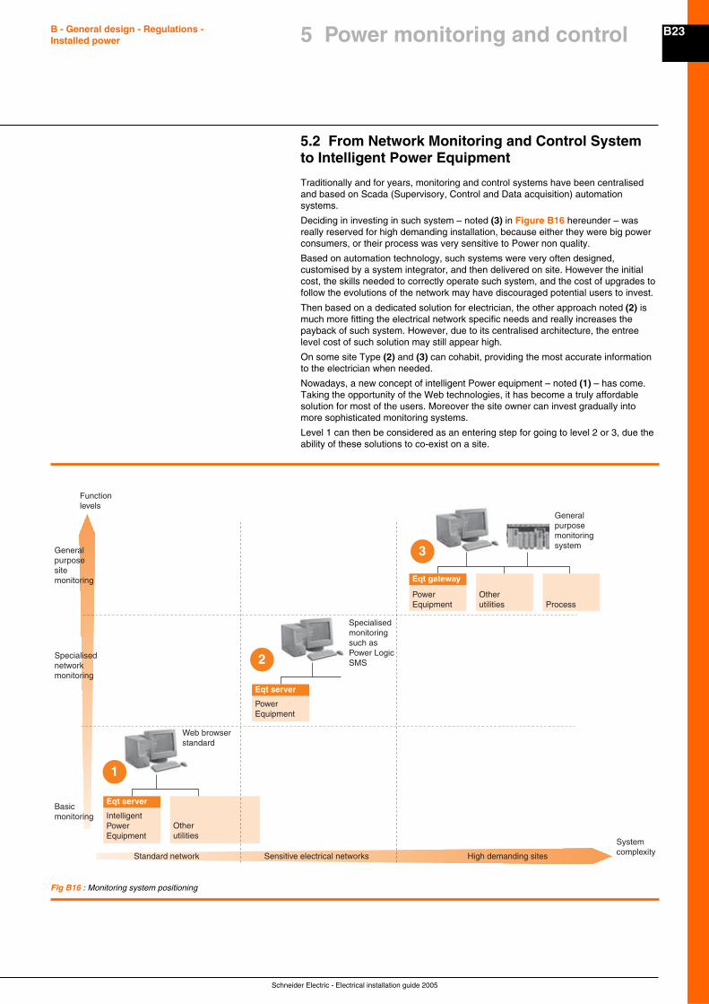
B23
Schneider Electric - Electrical installation guide 2005
B - General design - Regulations -Installed power
Specialised monitoringsuch as Power Logic SMS
Wstandard
eb browser
PowerEquipment
Otherutilities Process
Eqt gateway
1
2
3
IntelligentPowerEquipment
Otherutilities
Eqt server
PowerEquipment
Eqt server
General purposesite monitoring
Functionlevels
Specialisednetworkmonitoring
Basicmonitoring
Standard network Sensitive electrical networks High demanding sites
Systemcomplexity
General purposemonitoring system
Fig B16 : Monitoring system positioning
5.2 From Network Monitoring and Control Systemto Intelligent Power Equipment
Traditionally and for years, monitoring and control systems have been centralisedand based on Scada (Supervisory, Control and Data acquisition) automationsystems.
Deciding in investing in such system – noted (3) in Figure B16 hereunder – wasreally reserved for high demanding installation, because either they were big powerconsumers, or their process was very sensitive to Power non quality.
Based on automation technology, such systems were very often designed,customised by a system integrator, and then delivered on site. However the initialcost, the skills needed to correctly operate such system, and the cost of upgrades tofollow the evolutions of the network may have discouraged potential users to invest.
Then based on a dedicated solution for electrician, the other approach noted (2) ismuch more fitting the electrical network specific needs and really increases thepayback of such system. However, due to its centralised architecture, the entreelevel cost of such solution may still appear high.
On some site Type (2) and (3) can cohabit, providing the most accurate informationto the electrician when needed.
Nowadays, a new concept of intelligent Power equipment – noted (1) – has come.Taking the opportunity of the Web technologies, it has become a truly affordablesolution for most of the users. Moreover the site owner can invest gradually intomore sophisticated monitoring systems.
Level 1 can then be considered as an entering step for going to level 2 or 3, due theability of these solutions to co-exist on a site.
5 Power monitoring and control
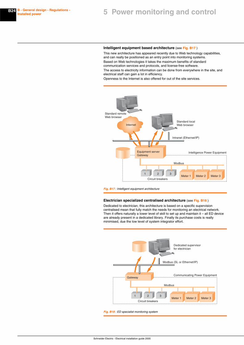
Schneider Electric - Electrical installation guide 2005
B24 B - General design - Regulations -Installed power
Meter 11 2 3
Circuit breakersMeter 2 Meter 3
Equipment serverGateway
Modbus
Intelligence Power Equipment
Standard remoteWeb browser
Standard local Web browser
Intranet (Ethernet/IP)
Internet
Intelligent equipment based architecture (see Fig. B17 )
This new architecture has appeared recently due to Web technology capabilities,and can really be positioned as an entry point into monitoring systems.Based on Web technologies it takes the maximum benefits of standardcommunication services and protocols, and license-free software.The access to electricity information can be done from everywhere in the site, andelectrical staff can gain a lot in efficiency.Openness to the Internet is also offered for out of the site services.
Fig. B17 : Intelligent equipment architecture
Electrician specialized centralised architecture (see Fig. B18 )
Dedicated to electrician, this architecture is based on a specific supervisioncentralised mean that fully match the needs for monitoring an electrical network.Then it offers naturally a lower level of skill to set up and maintain it – all ED deviceare already present in a dedicated library. Finally its purchase costs is reallyminimised, due the low level of system integrator effort.
Fig. B18 : ED specialist monitoring system
Meter 1 Meter 2 Meter 3
Gateway
Modbus
Communicating Power Equipment
Dedicated supervisorfor electrician
Modbus (SL or Ethernet/IP)
Circuit breakers
1 2 3
5 Power monitoring and control
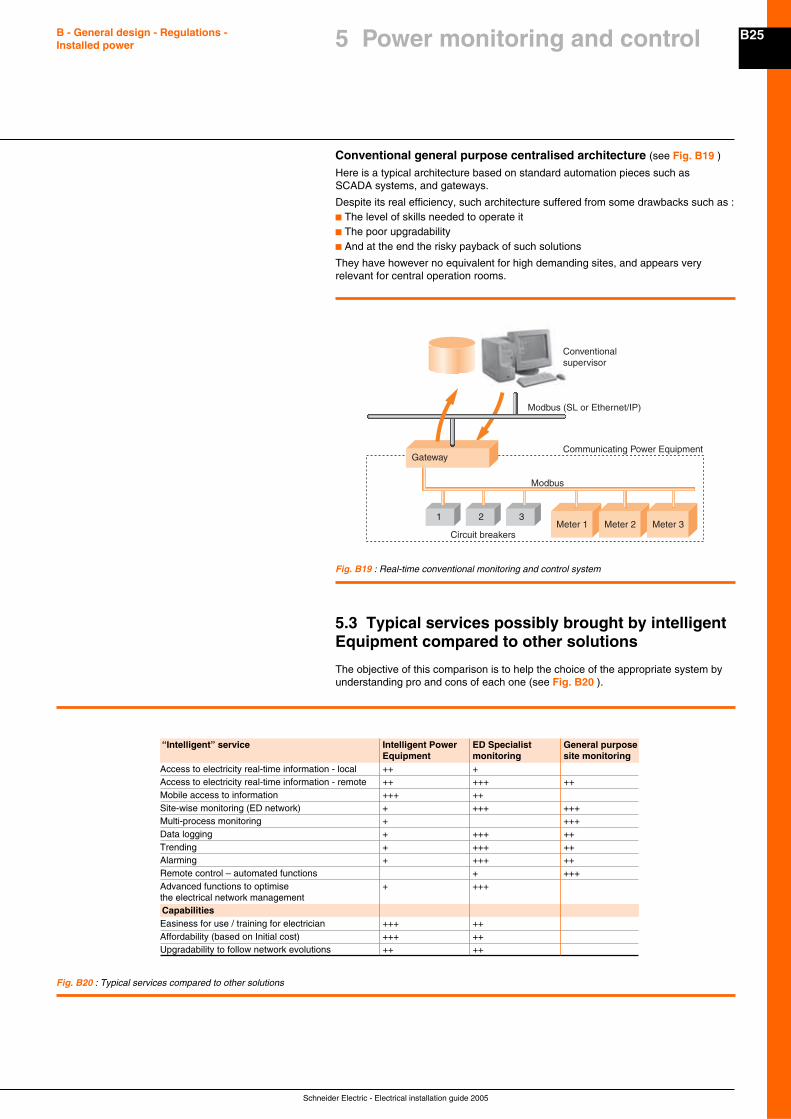
B25
Schneider Electric - Electrical installation guide 2005
B - General design - Regulations -Installed power
Conventional general purpose centralised architecture (see Fig. B19 )
Here is a typical architecture based on standard automation pieces such asSCADA systems, and gateways.
Despite its real efficiency, such architecture suffered from some drawbacks such as :c The level of skills needed to operate itc The poor upgradabilityc And at the end the risky payback of such solutions
They have however no equivalent for high demanding sites, and appears veryrelevant for central operation rooms.
Meter 1 Meter 2 Meter 3
Gateway
Modbus
Conventionalsupervisor
Modbus (SL or Ethernet/IP)
Communicating Power Equipment
Circuit breakers
1 2 3
5.3 Typical services possibly brought by intelligentEquipment compared to other solutions
The objective of this comparison is to help the choice of the appropriate system byunderstanding pro and cons of each one (see Fig. B20 ).
“Intelligent” service Intelligent Power ED Specialist General purposeEquipment monitoring site monitoring
Access to electricity real-time information - local ++ +Access to electricity real-time information - remote ++ +++ ++Mobile access to information +++ ++Site-wise monitoring (ED network) + +++ +++Multi-process monitoring + +++Data logging + +++ ++Trending + +++ ++Alarming + +++ ++Remote control – automated functions + +++Advanced functions to optimise + +++the electrical network managementCapabilitiesEasiness for use / training for electrician +++ ++Affordability (based on Initial cost) +++ ++Upgradability to follow network evolutions ++ ++
Fig. B20 : Typical services compared to other solutions
Fig. B19 : Real-time conventional monitoring and control system
5 Power monitoring and control
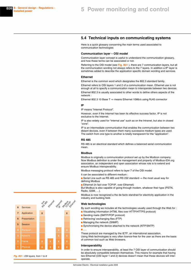
Schneider Electric - Electrical installation guide 2005
B26 B - General design - Regulations -Installed power
5.4 Technical inputs on communicating systems
Here is a quick glossary concerning the main terms used associated tocommunication technologies
Communication layer – OSI modelCommunication layer concept is useful to understand the communication glossary,and how these terms can be associated or not.
Referring to the OSI model (see Fig. B21 ), there are 7 communication layers, but allthe communication wording not always refers to the 7 layers. In addition a 8th layer issometimes added to describe the application specific domain wording and services.
EthernetEthernet is the common word which designates the 802.3 standard family.
Ethernet refers to OSI layers 1 and 2 of a communication mean. Ethernet use is notenough at all to specify a communication mean to interoperate between two devices.
Ethernet 802.3 is usually associated to other words to define others aspects of thenetwork :
Ethernet 802.3 10 Base T ⇒ means Ethernet 10Mb/s using RJ45 connector
IPIP means “Internet Protocol”.
However, even if the Internet has been its effective success factor, IP is notexclusive to the Internet.
IP is also widely used for “internal use” such as on the Intranet, but also in closed“zone”.
IP is an intermediate communication that enables the communication between twodistant devices, even if between them many successive medium types are used.The switch from one type to another is totally transparent for the “application”.
RS 485RS 485 is an electrical standard which defines a balanced serial communicationmean.
ModbusModbus is originally a communication protocol set up by the Modicon company.Now Modbus definition is under the management and property of Modbus-IDA.orgassociation, an independent and open association whose role is to extend andensure Modbus interoperability.
Modbus messaging protocol refers to layer 7 of the OSI model.
It can be associated to different medium :c Serial Line such as RS 485 and RS 232 standard ⇒ the most usual way fordefining Modbusc Ethernet (in fact over TCP/IP, over Ethernet)But Modbus is also capable of going through modem, whatever their type (PSTN,Radio, GSM, …).
Modbus is now recognized a the de-facto standrad for electricity application in theindustry and building field.
Web technologiesBy such wording we includes all the technologies usually used through the Web for :c Visualising information (HTML files over HTTP/HTTPS protocol)c Sending mails (SMTP/POP protocol)c Retrieving/ exchanging files (FTP)c Managing the network (SNMP)c Synchronising the device attached to the network (NTP/SNTP)c ….
These protocol are managed by the IETF, an international association.Using Web technologies is very often licence-free for the user as there are the basisof common tool such as Web browsers.
InteroperabilityIn order to ensure interoperability, at least the 7 OSI layer of communication shouldbe absolutely compatible between themselves. This means for example that havingtwo Ethernet (OSI layer 1 and 2) devices doesn’t mean that these devices will inter-operate.
Fig. B21 : OSI layers, from 1 to 8
Physical1 X
X
X
X
X
X
X
X X
X
X X
X X
Frame2
Network3
Transport4
Session5
Presentation6
Application7
Services
bus
Ether
net
RS 485
Ether
net
IP Mod
bus
TCP/IP
Ether
net
8
5 Power monitoring and control

B27
Schneider Electric - Electrical installation guide 2005
B - General design - Regulations -Installed power
5.5 Main constraints to take into account to designa communicating or intelligent power equipment
Equipment bus choiceHere are the main constraints to evaluate when choosing a communication network :c Openness and maturityc Proven ability to run in harsh Electrical environmentc Availability of bus compliant Power Devices with interoperability guaranteec Level of effort at the Power Equipment interface to make it communicating with therest of the system (seamless architecture availability)c Bus communication accessories to ease the wiring inside the cubicle.
Modbus over serial line is today one of the most stable communication mean in theElectrical Distribution environment, and compatible with most of 3d party devices.It has also been chosen by most of the manufacturers as their preferred network.Its easy and seamless openness to Ethernet is a guarantee for easy integration intothe rest of the system. It can also been seen as an easy way for upgrading in thefuture, without impact on connected applications.
Equipment bus topologyEquipment bus topology must be flexible enough to be spread on the Equipmentstructure.
What is also important is the disconnectability of sections within the powerequipment for transportation.
Usually there are needs of (impedance) termination at the ends of the bus.
The higher the bus speed is, the more sensitive to wiring, terminations andgrounding, the bus is.
Front communication socketIn order to ease the work of operators, introducing a socket on the front door of theequipment may be of great benefit.
This option will be even more effective if from this switchboard, the operator can notonly have access to information related to the connected power Equipment, but alsoto the rest of the site (for exemple downstream or upstream switchboard).
Auxiliary powerIn the same way as communication bus, auxiliary power has to be distributed to themain Power devices. Isolated Auxiliary DC Power is usually required.
Its distribution may be merged with the communication means : the same cableincludes communication and auxiliary power.
Communication accessoriesCommunication accessories may be necessary to ease the wiring and themaintenance of the switchboard. It then offers higher ease of reading andunderstanding the internal wiring of the switchboard. It may also make it possible thedisconnection of a communicating device, on line.
Electrical measurement optionsMeasurement is one of the foundation of Power monitoring. It may appear in thefuture as a systematically required feature.
There are mainly two basic concepts for introducing measurement into a PowerEquipment :c Implement TCs on cable or busbar. This may take space but this is the onlysolution for retrofitting an installation.c Use multifunction protection relays that possibly embed such feature and whichare upgradable in that sense.
Even if todays’ requirement doesn’t ask for measurement, making some provisionsfor introducing it later makes a lot of sense : either choosing power devices that canevolve to measurement inside devices, or reserve the necessary space for addingCTs eventually.
5 Power monitoring and control
Schneider Electric - Electrical installation guide 2005
C1
Chapter CConnection to the HV utilitydistribution network
Contents
Supply of power at high voltage C2
1.1 Power supply characteristics of high voltage C2utility distribution network
1.2 Different HV service connections C11
1.3 Some operational aspects of HV distribution networks C12
Procedure for the establishment of a new substation C14
2.1 Preliminary informations C14
2.2 Project studies C15
2.3 Implementation C15
2.4 Commissioning C15
Protection aspect C16
3.1 Protection against electric shocks C16
3.2 Protection of transformer and circuits C17
3.3 Interlocks and conditioned operations C19
The consumer substation with LV metering C22
4.1 General C22
4.2 Choice of panels C22
4.3 Choice of HV switchgear panel for a transformer circuit C25
4.4 Choice of MV/LV transformer C25
The consumer substation with HV metering C30
5.1 General C30
5.2 Choice of panels C32
5.3 Parallel operation of transformers C33
Constitution of HV/LV distribution substations C35
6.1 Different types of substation C35
6.2 Indoor substation C35
6.3 Outdoor substation C37
2
1
3
4
5
6
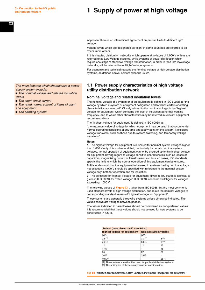
Schneider Electric - Electrical installation guide 2005
C2
C - Connection to the HV publicdistribution network
At present there is no international agreement on precise limits to define “High”voltage.
Voltage levels which are designated as “high” in some countries are referred to as“medium” in others.
In this chapter, distribution networks which operate at voltages of 1,000 V or less arereferred to as Low-Voltage systems, while systems of power distribution whichrequire one stage of stepdown voltage transformation, in order to feed into lowvoltagenetworks, will be referred to as High- Voltage systems.
For economic and technical reasons the nominal voltage of high-voltage distributionsystems, as defined above, seldom exceeds 35 kV.
1.1 Power supply characteristics of high voltageutility distribution network
Nominal voltage and related insulation levelsThe nominal voltage of a system or of an equipment is defined in IEC 60038 as “thevoltage by which a system or equipment designated and to which certain operatingcharacteristics are referred”. Closely related to the nominal voltage is the “highestvoltage for equipment” which concerns the level of insulation at normal workingfrequency, and to which other characteristics may be referred in relevant equipmentrecommendations.
The “highest voltage for equipment” is defined in IEC 60038 as:“the maximum value of voltage for which equipment may be used, that occurs undernormal operating conditions at any time and at any point on the system. It excludesvoltage transients, such as those due to system switching, and temporary voltagevariations”.
Notes:1- The highest voltage for equipment is indicated for nominal system voltages higherthan 1,000 V only. It is understood that, particularly for certain nominal systemvoltages, normal operation of equipment cannot be ensured up to this highest voltagefor equipment, having regard to voltage sensitive characteristics such as losses ofcapacitors, magnetizing current of transformers, etc. In such cases, IEC standardsspecify the limit to which the normal operation of this equipment can be ensured.2- It is understood that the equipment to be used in systems having nominal voltagenot exceeding 1,000 V should be specified with reference to the nominal systemvoltage only, both for operation and for insulation.3- The definition for “highest voltage for equipment” given in IEC 60038 is identical togiven in IEC 60694 for “rated voltage”. IEC 60694 concerns switchgear for voltagesexceeding 1,000 V.
The following values of Figure C1 , taken from IEC 60038, list the most-commonlyused standard levels of high-voltage distribution, and relate the nominal voltages tocorresponding standard values of “Highest Voltage for Equipment”.
These systems are generally three-wire systems unless otherwise indicated. Thevalues shown are voltages between phases.
The values indicated in parentheses should be considered as non-preferred values.It is recommended that these values should not be used for new systems to beconstructed in future.
1 Supply of power at high voltage
The main features which characterize a power-supply system include:c The nominal voltage and related insulationlevelsc The short-circuit currentc The rated normal current of items of plantand equipmentc The earthing system
Fig. C1 : Relation between nominal system voltages and highest voltages for the equipment
Series I (pour réseaux à 50 Hz et 60 Hz)Highest voltage for equipement Nominal system voltage(kV) (kV)3.6 (1) 3.3 (1) 3 (1)
7.2 (1) 6.6 (1) 6 (1)
12 11 1017.5 - 1524 22 2036 (2) 33 (2) -40.5 (2) - 35 (2)
(1) These values should not be used for public distribution systems.(2) The unification of these values is under consideration.
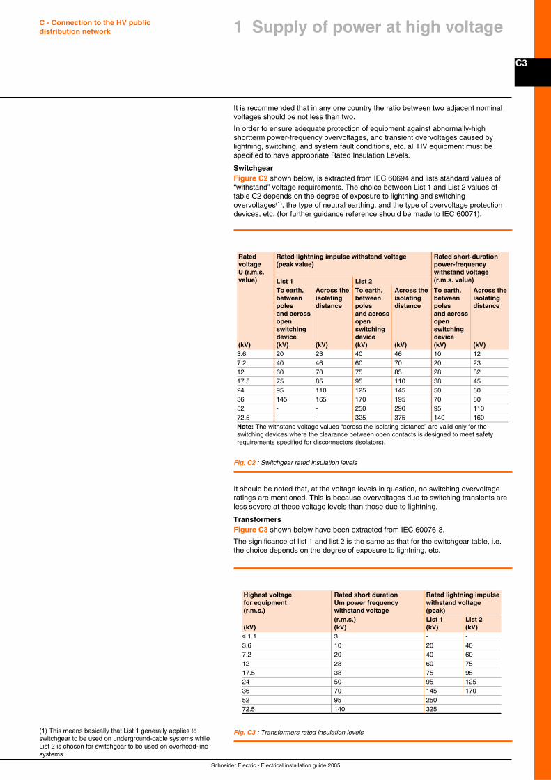
C3
Schneider Electric - Electrical installation guide 2005
C - Connection to the HV publicdistribution network
It is recommended that in any one country the ratio between two adjacent nominalvoltages should be not less than two.
In order to ensure adequate protection of equipment against abnormally-highshortterm power-frequency overvoltages, and transient overvoltages caused bylightning, switching, and system fault conditions, etc. all HV equipment must bespecified to have appropriate Rated Insulation Levels.
SwitchgearFigure C2 shown below, is extracted from IEC 60694 and lists standard values of“withstand” voltage requirements. The choice between List 1 and List 2 values oftable C2 depends on the degree of exposure to lightning and switchingovervoltages(1), the type of neutral earthing, and the type of overvoltage protectiondevices, etc. (for further guidance reference should be made to IEC 60071).
(1) This means basically that List 1 generally applies toswitchgear to be used on underground-cable systems whileList 2 is chosen for switchgear to be used on overhead-linesystems.
Rated Rated lightning impulse withstand voltage Rated short-durationvoltage (peak value) power-frequencyU (r.m.s. withstand voltagevalue) List 1 List 2 (r.m.s. value)
To earth, Across the To earth, Across the To earth, Across thebetween isolating between isolating between isolatingpoles distance poles distance poles distanceand across and across and acrossopen open openswitching switching switchingdevice device device
(kV) (kV) (kV) (kV) (kV) (kV) (kV)3.6 20 23 40 46 10 127.2 40 46 60 70 20 2312 60 70 75 85 28 3217.5 75 85 95 110 38 4524 95 110 125 145 50 6036 145 165 170 195 70 8052 - - 250 290 95 11072.5 - - 325 375 140 160Note: The withstand voltage values “across the isolating distance” are valid only for theswitching devices where the clearance between open contacts is designed to meet safetyrequirements specified for disconnectors (isolators).
Fig. C2 : Switchgear rated insulation levels
It should be noted that, at the voltage levels in question, no switching overvoltageratings are mentioned. This is because overvoltages due to switching transients areless severe at these voltage levels than those due to lightning.
TransformersFigure C3 shown below have been extracted from IEC 60076-3.
The significance of list 1 and list 2 is the same as that for the switchgear table, i.e.the choice depends on the degree of exposure to lightning, etc.
Fig. C3 : Transformers rated insulation levels
Highest voltage Rated short duration Rated lightning impulsefor equipment Um power frequency withstand voltage(r.m.s.) withstand voltage (peak)
(r.m.s.) List 1 List 2(kV) (kV) (kV) (kV)i 1.1 3 - -3.6 10 20 407.2 20 40 6012 28 60 7517.5 38 75 9524 50 95 12536 70 145 17052 95 25072.5 140 325
1 Supply of power at high voltage
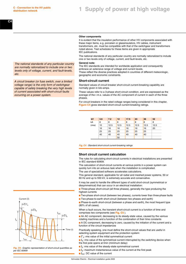
Schneider Electric - Electrical installation guide 2005
C4
C - Connection to the HV publicdistribution network
Other componentsIt is evident that the insulation performance of other HV components associated withthese major items, e.g. porcelain or glassinsulators, HV cables, instrumenttransformers, etc. must be compatible with that of the switchgear and transformersnoted above. Test schedules for these items are given in appropriateIEC publications.
The national standards of any particular country are normally rationalized to includeone or two levels only of voltage, current, and fault-levels, etc.
General note:The IEC standards are intended for worldwide application and consequentlyembrace an extensive range of voltage and current levels.These reflect the diverse practices adopted in countries of different meteorologic,geographic and economic constraints.
Short-circuit currentStandard values of circuit breaker short-circuit current-breaking capability arenormally given in kilo-amps.
These values refer to a 3-phase short-circuit condition, and are expressed as theaverage of the r.m.s. values of the AC component of current in each of the threephases.
For circuit breakers in the rated voltage ranges being considered in this chapter,Figure C4 gives standard short-circuit current-breaking ratings.
The national standards of any particular countryare normally rationalized to include one or twolevels only of voltage, current, and fault-levels,etc.
A circuit breaker (or fuse switch, over a limitedvoltage range) is the only form of switchgearcapable of safely breaking the very high levelsof current associated with short-circuit faultsoccurring on a power system.
Fig. C4 : Standard short-circuit current-breaking ratings
tmin
Current (I)
IDC
Ip
Time (t)
2rI''k
2rIk
2rIb
Fig. C5 : Graphic representation of short-circuit quantities asper IEC 60909
kV 3.6 7.2 12 17.5 24 36 52kA 8 8 8 8 8 8 8(rms) 10 12.5 12.5 12.5 12.5 12.5 12.5
16 16 16 16 16 16 2025 25 25 25 25 2540 40 40 40 40 40
50
Short circuit current calculationThe rules for calculating short-circuit currents in electrical installations are presentedin IEC standard 60909.The calculation of short-circuit currents at various points in a power system canquickly turn into an arduous task when the installation is complicated.The use of specialized software accelerates calculations.This general standard, applicable for all radial and meshed power systems, 50 or60 Hz and up to 550 kV, is extremely accurate and conservative.
It may be used to handle the different types of solid short-circuit (symmetrical ordissymmetrical) that can occur in an electrical installation:c Three-phase short-circuit (all three phases), generally the type producing thehighest currentsc Two-phase short-circuit (between two phases), currents lower than three-phase faultsc Two-phase-to-earth short-circuit (between two phases and earth)c Phase-to-earth short-circuit (between a phase and earth), the most frequent type(80% of all cases).
When a fault occurs, the transient short-circuit current is a function of time andcomprises two components (see Fig. C5 ).c An AC component, decreasing to its steady-state value, caused by the variousrotating machines and a function of the combination of their time constantsc A DC component, decreasing to zero, caused by the initiation of the current and afunction of the circuit impedances
Practically speaking, one must define the short-circuit values that are useful inselecting system equipment and the protection system:c I’’k: rms value of the initial symmetrical currentc Ib: rms value of the symmetrical current interrupted by the switching device whenthe first pole opens at tmin (minimum delay)c Ik: rms value of the steady-state symmetrical currentc Ip: maximum instantaneous value of the current at the first peakc IDC: DC value of the current
1 Supply of power at high voltage
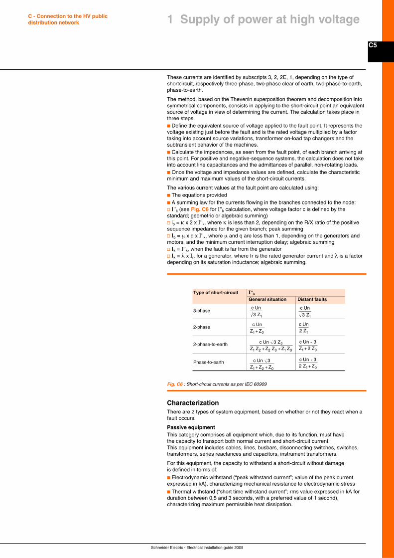
C5
Schneider Electric - Electrical installation guide 2005
C - Connection to the HV publicdistribution network 1 Supply of power at high voltage
These currents are identified by subscripts 3, 2, 2E, 1, depending on the type ofshortcircuit, respectively three-phase, two-phase clear of earth, two-phase-to-earth,phase-to-earth.
The method, based on the Thevenin superposition theorem and decomposition intosymmetrical components, consists in applying to the short-circuit point an equivalentsource of voltage in view of determining the current. The calculation takes place inthree steps.c Define the equivalent source of voltage applied to the fault point. It represents thevoltage existing just before the fault and is the rated voltage multiplied by a factortaking into account source variations, transformer on-load tap changers and thesubtransient behavior of the machines.c Calculate the impedances, as seen from the fault point, of each branch arriving atthis point. For positive and negative-sequence systems, the calculation does not takeinto account line capacitances and the admittances of parallel, non-rotating loads.c Once the voltage and impedance values are defined, calculate the characteristicminimum and maximum values of the short-circuit currents.
The various current values at the fault point are calculated using:c The equations providedc A summing law for the currents flowing in the branches connected to the node:v I’’k (see Fig. C6 for I’’k calculation, where voltage factor c is defined by thestandard; geometric or algebraic summing)v ip = κ x 2 x I’’k, where κ is less than 2, depending on the R/X ratio of the positivesequence impedance for the given branch; peak summingv Ib = µ x q x I’’k, where µ and q are less than 1, depending on the generators andmotors, and the minimum current interruption delay; algebraic summingv Ik = I’’k, when the fault is far from the generatorv Ik = λ x Ir, for a generator, where Ir is the rated generator current and λ is a factordepending on its saturation inductance; algebraic summing.
Fig. C6 : Short-circuit currents as per IEC 60909
Type of short-circuit I’’kGeneral situation Distant faults
3-phasec Un
Z
13c Un
Z
13
2-phase c UnZ Z
1 2+
c UnZ
12
2-phase-to-earth c UnZ Z Z Z Z Z
3 Z
2
1 2 2 0 1 0+ +
c UnZ Z
3 1 0+ 2
Phase-to-earth c UnZ Z Z
3
1 2 0+ +
c UnZ Z 3 1 02 +
CharacterizationThere are 2 types of system equipment, based on whether or not they react when afault occurs.
Passive equipmentThis category comprises all equipment which, due to its function, must havethe capacity to transport both normal current and short-circuit current.This equipment includes cables, lines, busbars, disconnecting switches, switches,transformers, series reactances and capacitors, instrument transformers.
For this equipment, the capacity to withstand a short-circuit without damageis defined in terms of:
c Electrodynamic withstand (“peak withstand current”; value of the peak currentexpressed in kA), characterizing mechanical resistance to electrodynamic stress
c Thermal withstand (“short time withstand current”; rms value expressed in kA forduration between 0,5 and 3 seconds, with a preferred value of 1 second),characterizing maximum permissible heat dissipation.
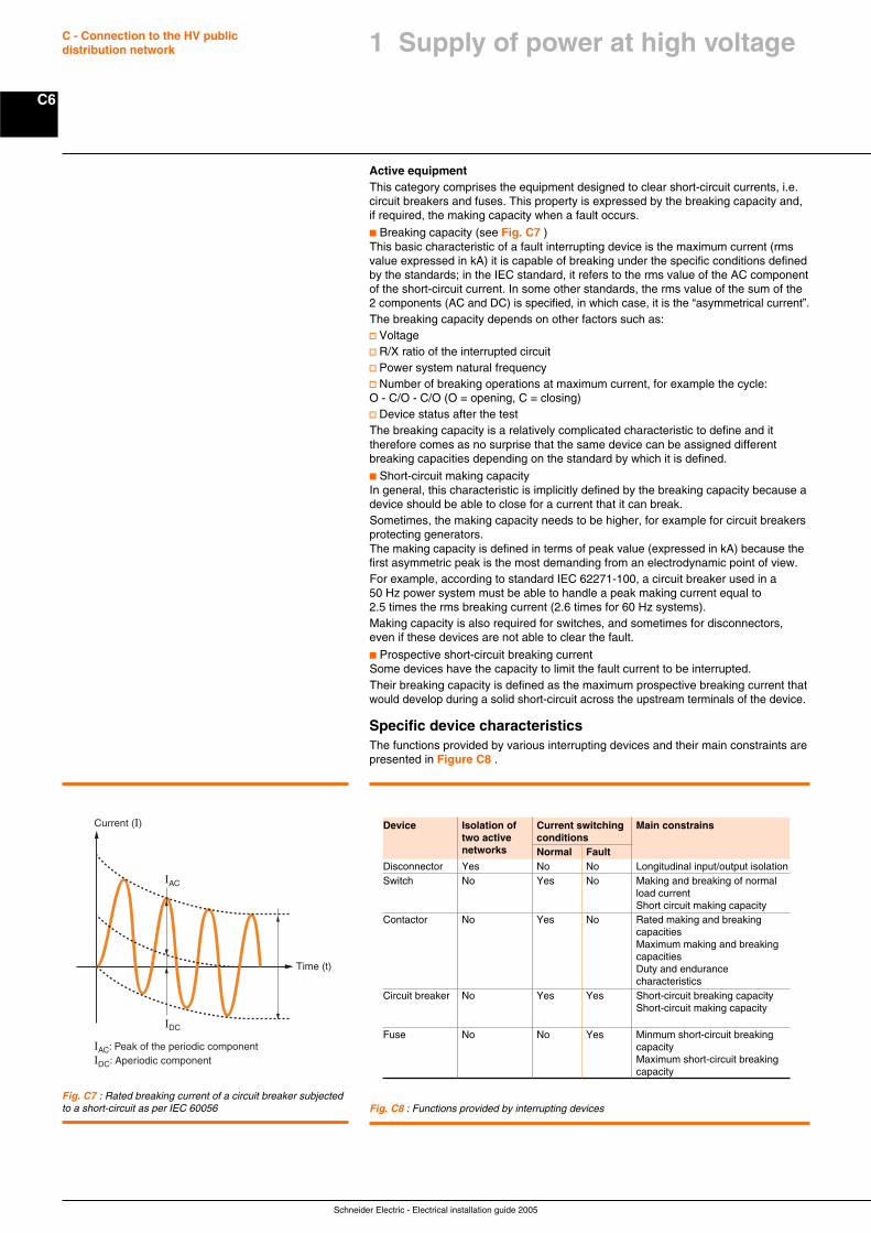
Schneider Electric - Electrical installation guide 2005
C6
C - Connection to the HV publicdistribution network
Active equipmentThis category comprises the equipment designed to clear short-circuit currents, i.e.circuit breakers and fuses. This property is expressed by the breaking capacity and,if required, the making capacity when a fault occurs.
c Breaking capacity (see Fig. C7 )This basic characteristic of a fault interrupting device is the maximum current (rmsvalue expressed in kA) it is capable of breaking under the specific conditions definedby the standards; in the IEC standard, it refers to the rms value of the AC componentof the short-circuit current. In some other standards, the rms value of the sum of the2 components (AC and DC) is specified, in which case, it is the “asymmetrical current”.The breaking capacity depends on other factors such as:v Voltagev R/X ratio of the interrupted circuitv Power system natural frequencyv Number of breaking operations at maximum current, for example the cycle:O - C/O - C/O (O = opening, C = closing)v Device status after the testThe breaking capacity is a relatively complicated characteristic to define and ittherefore comes as no surprise that the same device can be assigned differentbreaking capacities depending on the standard by which it is defined.
c Short-circuit making capacityIn general, this characteristic is implicitly defined by the breaking capacity because adevice should be able to close for a current that it can break.Sometimes, the making capacity needs to be higher, for example for circuit breakersprotecting generators.The making capacity is defined in terms of peak value (expressed in kA) because thefirst asymmetric peak is the most demanding from an electrodynamic point of view.For example, according to standard IEC 62271-100, a circuit breaker used in a50 Hz power system must be able to handle a peak making current equal to2.5 times the rms breaking current (2.6 times for 60 Hz systems).Making capacity is also required for switches, and sometimes for disconnectors,even if these devices are not able to clear the fault.
c Prospective short-circuit breaking currentSome devices have the capacity to limit the fault current to be interrupted.Their breaking capacity is defined as the maximum prospective breaking current thatwould develop during a solid short-circuit across the upstream terminals of the device.
Specific device characteristicsThe functions provided by various interrupting devices and their main constraints arepresented in Figure C8 .
Current (I)
IAC
IAC: Peak of the periodic componentIDC: Aperiodic component
IDC
Time (t)
Fig. C7 : Rated breaking current of a circuit breaker subjectedto a short-circuit as per IEC 60056 Fig. C8 : Functions provided by interrupting devices
Device Isolation of Current switching Main constrainstwo active conditionsnetworks Normal Fault
Disconnector Yes No No Longitudinal input/output isolationSwitch No Yes No Making and breaking of normal
load currentShort circuit making capacity
Contactor No Yes No Rated making and breakingcapacitiesMaximum making and breakingcapacitiesDuty and endurancecharacteristics
Circuit breaker No Yes Yes Short-circuit breaking capacityShort-circuit making capacity
Fuse No No Yes Minmum short-circuit breakingcapacityMaximum short-circuit breakingcapacity
1 Supply of power at high voltage

C7
Schneider Electric - Electrical installation guide 2005
C - Connection to the HV publicdistribution network 1 Supply of power at high voltage
Rated normal currentThe rated normal current is defined as “the r.m.s. value of the current which can becarried continuously at rated frequency with a temperature rise not exceeding thatspecified by the relevant product standard”.
The rated normal current requirements for switchgear are decided at the substationdesign stage.
The most common normal current rating for general-purpose HV distributionswitchgear is 400 A.
In industrial areas and high-load-density urban districts, circuits rated at 630 A aresometimes required, while at bulk-supply substations which feed into HV networks,
800 A; 1,250 A; 1,600 A; 2,500 A and 4,000 A circuit breakers are listed as standardratings for incoming-transformer circuits, bus-section and bus-coupler CBs, etc.
For HV/LV transformer with a normal primary current up to roughly 60A, a HVswitch-fuse combination can be used . For higher primary currents, switch-fusecombination does not have the required performances.
There are no IEC-recommended normal current rating tables for the combination inthese cases. The actual rating will be given by the switch-fuse manufacturer,according to the fuse characteristics, and details of the transformer, such as:c Normal current at HVc Permissible overcurrent and its durationc Max. peak and duration of the transformer energization inrush magnetizing currentc Off-circuit tapping-switch position, etc. as shown in the example given inAppendix A of IEC 62271-105, and summarized in Appendix C1 of this guide.
In such a scheme, the load-break switch must be suitably rated to trip automatically,e.g. by relays, at low fault-current levels which must cover (by an appropriatemargin) the rated minimum breaking current of the HV fuses. In this way, high valuesof fault current which are beyond the breaking capability of the load-break switch willbe cleared by the fuses, while low fault-current values, that cannot be correctlycleared by the fuses, will be cleared by the relay-operated load-break switch.
Appendix C1 gives further information on this arrangement, as applied to HV switch-fuse combination units.
Influence of the ambient temperature and altitude on the rated currentNormal-current ratings are assigned to all current-carrying electrical appliances, andupper limits are decided by the acceptable temperature rise caused by theI2R (watts) dissipated in the conductors, (where I = r.m.s. current in amperes andR = the resistance of the conductor in ohms), together with the heat produced bymagnetic-hysteresis and eddy-current losses in motors, transformers, etc. anddielectric losses in cables and capacitors, where appropriate.
The temperature rise above the ambient temperature will depend mainly on the rateat which the heat is removed. For example, large currents can be passed throughelectric motor windings without causing them to overheat, simply because a coolingfan fixed to the shaft of the motor removes the heat at the same rate as it isproduced, and so the temperature reaches a stable value below that which coulddamage the insulation and result in a burnt-out motor.
Oil- and/or air-cooled transformers are among the most widely known examples ofsuch “forced-cooling” techniques.
The normal-current values recommended by IEC are based on ambient-airtemperatures common to temperate climates at altitudes not exceeding1,000 metres, so that items which depend on natural cooling by radiation and air-convection will overheat if operated at rated normal current in a tropical climate and/or at altitudes exceeding 1,000 metres. In such cases, the equipment has to bederated, i.e. be assigned a lower value of normal current rating.
The case of transformer is addressed in IEC 60076-2.
In the case of force-cooled transformers it is generally sufficient to provide sunshields, and increase the oil-cooling radiator surfaces, the amount of cooling oil, thepower of the circulating-oil pumps, and the size of the aircirculating fans, to maintainthe original IEC rating.
For switchgear, the manufacturer should be asked about the proper derating to eapplied according to the actual operating conditions.
The most common normal current rating forgeneral-purpose HV distribution switchgear is400 A.
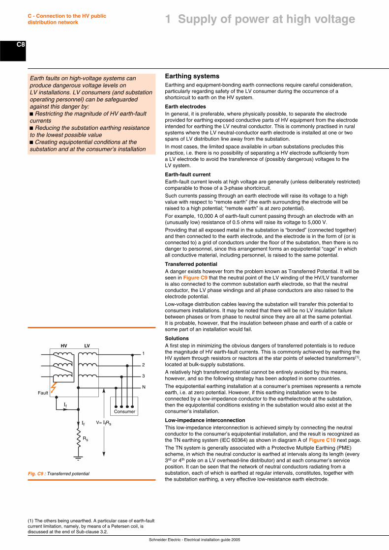
Schneider Electric - Electrical installation guide 2005
C8
C - Connection to the HV publicdistribution network
Earthing systemsEarthing and equipment-bonding earth connections require careful consideration,particularly regarding safety of the LV consumer during the occurrence of ashortcircuit to earth on the HV system.
Earth electrodesIn general, it is preferable, where physically possible, to separate the electrodeprovided for earthing exposed conductive parts of HV equipment from the electrodeintended for earthing the LV neutral conductor. This is commonly practised in ruralsystems where the LV neutral-conductor earth electrode is installed at one or twospans of LV distribution line away from the substation.
In most cases, the limited space available in urban substations precludes thispractice, i.e. there is no possibility of separating a HV electrode sufficiently froma LV electrode to avoid the transference of (possibly dangerous) voltages to theLV system.
Earth-fault currentEarth-fault current levels at high voltage are generally (unless deliberately restricted)comparable to those of a 3-phase shortcircuit.
Such currents passing through an earth electrode will raise its voltage to a highvalue with respect to “remote earth” (the earth surrounding the electrode will beraised to a high potential; “remote earth” is at zero potential).
For example, 10,000 A of earth-fault current passing through an electrode with an(unusually low) resistance of 0.5 ohms will raise its voltage to 5,000 V.
Providing that all exposed metal in the substation is “bonded” (connected together)and then connected to the earth electrode, and the electrode is in the form of (or isconnected to) a grid of conductors under the floor of the substation, then there is nodanger to personnel, since this arrangement forms an equipotential “cage” in whichall conductive material, including personnel, is raised to the same potential.
Transferred potentialA danger exists however from the problem known as Transferred Potential. It will beseen in Figure C9 that the neutral point of the LV winding of the HV/LV transformeris also connected to the common substation earth electrode, so that the neutralconductor, the LV phase windings and all phase conductors are also raised to theelectrode potential.
Low-voltage distribution cables leaving the substation will transfer this potential toconsumers installations. It may be noted that there will be no LV insulation failurebetween phases or from phase to neutral since they are all at the same potential.It is probable, however, that the insulation between phase and earth of a cable orsome part of an installation would fail.
SolutionsA first step in minimizing the obvious dangers of transferred potentials is to reducethe magnitude of HV earth-fault currents. This is commonly achieved by earthing theHV system through resistors or reactors at the star points of selected transformers(1),located at bulk-supply substations.
A relatively high transferred potential cannot be entirely avoided by this means,however, and so the following strategy has been adopted in some countries.
The equipotential earthing installation at a consumer’s premises represents a remoteearth, i.e. at zero potential. However, if this earthing installation were to beconnected by a low-impedance conductor to the earthelectrode at the substation,then the equipotential conditions existing in the substation would also exist at theconsumer’s installation.
Low-impedance interconnectionThis low-impedance interconnection is achieved simply by connecting the neutralconductor to the consumer’s equipotential installation, and the result is recognized asthe TN earthing system (IEC 60364) as shown in diagram A of Figure C10 next page.
The TN system is generally associated with a Protective Multiple Earthing (PME)scheme, in which the neutral conductor is earthed at intervals along its length (every3rd or 4th pole on a LV overhead-line distributor) and at each consumer’s serviceposition. It can be seen that the network of neutral conductors radiating from asubstation, each of which is earthed at regular intervals, constitutes, together withthe substation earthing, a very effective low-resistance earth electrode.
(1) The others being unearthed. A particular case of earth-faultcurrent limitation, namely, by means of a Petersen coil, isdiscussed at the end of Sub-clause 3.2.
Earth faults on high-voltage systems canproduce dangerous voltage levels onLV installations. LV consumers (and substationoperating personnel) can be safeguardedagainst this danger by:c Restricting the magnitude of HV earth-faultcurrentsc Reducing the substation earthing resistanceto the lowest possible valuec Creating equipotential conditions at thesubstation and at the consumer’s installation
N
3
2
1
Fault
HV LV
If
If
V= IfRs
Consumer
Rs
Fig. C9 : Transferred potential
1 Supply of power at high voltage
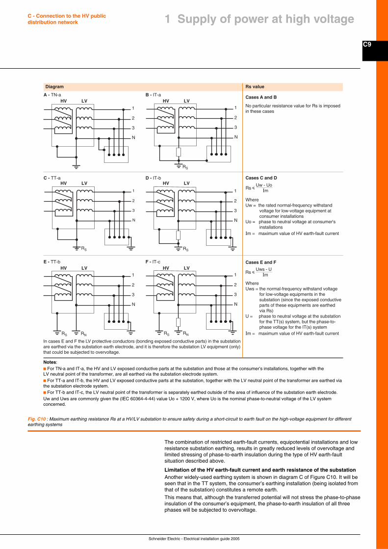
C9
Schneider Electric - Electrical installation guide 2005
C - Connection to the HV publicdistribution network 1 Supply of power at high voltage
The combination of restricted earth-fault currents, equipotential installations and lowresistance substation earthing, results in greatly reduced levels of overvoltage andlimited stressing of phase-to-earth insulation during the type of HV earth-faultsituation described above.
Limitation of the HV earth-fault current and earth resistance of the substationAnother widely-used earthing system is shown in diagram C of Figure C10. It will beseen that in the TT system, the consumer’s earthing installation (being isolated fromthat of the substation) constitutes a remote earth.
This means that, although the transferred potential will not stress the phase-to-phaseinsulation of the consumer’s equipment, the phase-to-earth insulation of all threephases will be subjected to overvoltage.
Fig. C10 : Maximum earthing resistance Rs at a HV/LV substation to ensure safety during a short-circuit to earth fault on the high-voltage equipment for differentearthing systems
N
3
2
1
Diagram Rs value
N
3
2
1HV LVHV LV
HV LVHV LV
HV LVHV LV
RS
Cases A and B
No particular resistance value for Rs is imposed in these cases
Cases C and D
WhereUw = the rated normal-frequency withstand voltage for low-voltage equipment at consumer installationsUo = phase to neutral voltage at consumer's installationsIm = maximum value of HV earth-fault current
WhereUws = the normal-frequency withstand voltage for low-voltage equipments in the substation (since the exposed conductive parts of these equipments are earthed via Rs)U = phase to neutral voltage at the substation for the TT(s) system, but the phase-to- phase voltage for the IT(s) systemIm = maximum value of HV earth-fault current
Rs iUw - Uo
Im
N
3
2
1
RS
N
3
2
1
RS
N
3
2
1
RNRS
N
3
2
1
RNRS
In cases E and F the LV protective conductors (bonding exposed conductive parts) in the substationare earthed via the substation earth electrode, and it is therefore the substation LV equipment (only) that could be subjected to overvoltage.
Cases E and F
Rs iUws - U
Im
B - IT-aA - TN-a
D - IT-bC - TT-a
F - IT-cE - TT-b
Notes:c For TN-a and IT-a, the HV and LV exposed conductive parts at the substation and those at the consumer’s installations, together with theLV neutral point of the transformer, are all earthed via the substation electrode system.c For TT-a and IT-b, the HV and LV exposed conductive parts at the substation, together with the LV neutral point of the transformer are earthed viathe substation electrode system.c For TT-b and IT-c, the LV neutral point of the transformer is separately earthed outside of the area of influence of the substation earth electrode.Uw and Uws are commonly given the (IEC 60364-4-44) value Uo + 1200 V, where Uo is the nominal phase-to-neutral voltage of the LV systemconcerned.
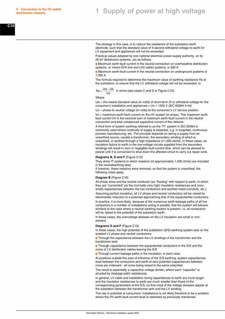
Schneider Electric - Electrical installation guide 2005
C10
C - Connection to the HV publicdistribution network
The strategy in this case, is to reduce the resistance of the substation earthelectrode, such that the standard value of 5-second withstand-voltage-to-earth forLV equipment and appliances will not be exceeded.
Practical values adopted by one national electrical power-supply authority, on its20 kV distribution systems, are as follows:c Maximum earth-fault current in the neutral connection on overheadline distributionsystems, or mixed (O/H line and U/G cable) systems, is 300 Ac Maximum earth-fault current in the neutral connection on underground systems is1,000 A
The formula required to determine the maximum value of earthing resistance Rs atthe substation, to ensure that the LV withstand voltage will not be exceeded, is:
RsUw Uo
=−Im
in ohms (see cases C and D in Figure C10).
Where
Uw = the lowest standard value (in volts) of short-term (5 s) withstand voltage for theconsumer’s installation and appliances = Uo + 1200 V (IEC 60364-4-44)
Uo = phase to neutral voltage (in volts) at the consumer’s LV service position
Im = maximum earth-fault current on the HV system (in amps). This maximum earthfault current Im is the vectorial sum of maximum earth-fault current in the neutralconnection and total unbalanced capacitive current of the network.
A third form of system earthing referred to as the “IT” system in IEC 60364 iscommonly used where continuity of supply is essential, e.g. in hospitals, continuous-process manufacturing, etc. The principle depends on taking a supply from anunearthed source, usually a transformer, the secondary winding of which isunearthed, or earthed through a high impedance (u1,000 ohms). In these cases, aninsulation failure to earth in the low-voltage circuits supplied from the secondarywindings will result in zero or negligible fault-current flow, which can be allowed topersist until it is convenient to shut-down the affected circuit to carry out repair work.
Diagrams B, D and F (Figure C10)They show IT systems in which resistors (of approximately 1,000 ohms) are includedin the neutralearthing lead.If however, these resistors were removed, so that the system is unearthed, thefollowing notes apply.
Diagram B (Figure C10)All phase wires and the neutral conductor are “floating” with respect to earth, to whichthey are “connected” via the (normally very high) insulation resistances and (verysmall) capacitances between the live conductors and earthed metal (conduits, etc.).
Assuming perfect insulation, all LV phase and neutral conductors will be raised byelectrostatic induction to a potential approaching that of the equipotential conductors.
In practice, it is more likely, because of the numerous earth-leakage paths of all liveconductors in a number of installations acting in parallel, that the system will behavesimilarly to the case where a neutral earthing resistor is present, i.e. all conductorswill be raised to the potential of the substation earth.
In these cases, the overvoltage stresses on the LV insulation are small or non-existent.
Diagrams D and F (Figure C10)In these cases, the high potential of the substation (S/S) earthing system acts on theisolated LV phase and neutral conductors:c Through the capacitance between the LV windings of the transformer and thetransformer tankc Through capacitance between the equipotential conductors in the S/S and thecores of LV distribution cables leaving the S/Sc Through current leakage paths in the insulation, in each case.
At positions outside the area of influence of the S/S earthing, system capacitancesexist between the conductors and earth at zero potential (capacitances betweencores are irrelevant - all cores being raised to the same potential).
The result is essentially a capacitive voltage divider, where each “capacitor” isshunted by (leakage path) resistances.
In general, LV cable and installation wiring capacitances to earth are much larger,and the insulation resistances to earth are much smaller than those of thecorresponding parameters at the S/S, so that most of the voltage stresses appear atthe substation between the transformer tank and the LV winding.
The rise in potential at consumers’ installations is not likely therefore to be a problemwhere the HV earth-fault current level is restricted as previously mentioned.
1 Supply of power at high voltage
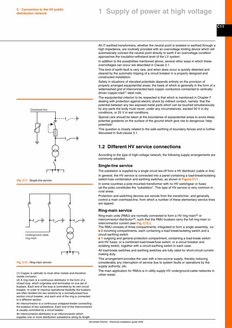
C11
Schneider Electric - Electrical installation guide 2005
C - Connection to the HV publicdistribution network 1 Supply of power at high voltage
All IT-earthed transformers, whether the neutral point is isolated or earthed through ahigh impedance, are routinely provided with an overvoltage limiting device which willautomatically connect the neutral point directly to earth if an overvoltage conditionapproaches the insulation-withstand level of the LV system.
In addition to the possibilities mentioned above, several other ways in which theseovervoltages can occur are described in Clause 3.1.
This kind of earth-fault is very rare, and when does occur is quickly detected andcleared by the automatic tripping of a circuit breaker in a properly designed andconstructed installation.
Safety in situations of elevated potentials depends entirely on the provision ofproperly arranged equipotential areas, the basis of which is generally in the form of awidemeshed grid of interconnected bare copper conductors connected to vertically-driven copper-clad(1) steel rods.
The equipotential criterion to be respected is that which is mentioned in Chapter Fdealing with protection against electric shock by indirect contact, namely: that thepotential between any two exposed metal parts which can be touched simultaneouslyby any parts the body must never, under any circumstances, exceed 50 V in dryconditions, or 25 V in wet conditions.
Special care should be taken at the boundaries of equipotential areas to avoid steeppotential gradients on the surface of the ground which give rise to dangerous “steppotentials”.
This question is closely related to the safe earthing of boundary fences and is furtherdiscussed in Sub-clause 3.1.
1.2 Different HV service connections
According to the type of high-voltage network, the following supply arrangements arecommonly adopted.
Single-line serviceThe substation is supplied by a single circuit tee-off from a HV distributor (cable or line).
In general, the HV service is connected into a panel containing a load-break/isolatingswitch-fuse combination and earthing switches, as shown in Figure C11 .
In some countries a pole-mounted transformer with no HV switchgear or fuses(at the pole) constitutes the “substation”. This type of HV service is very common inrural areas.
Protection and switching devices are remote from the transformer, and generallycontrol a main overhead-line, from which a number of these elementary service linesare tapped.
Ring-main serviceRing-main units (RMU) are normally connected to form a HV ring main(2) orinterconnector-distributor(2), such that the RMU busbars carry the full ring-main orinterconnector current (see Fig. C12 ).The RMU consists of three compartments, integrated to form a single assembly, viz:c 2 incoming compartments, each containing a load break/isolating switch and acircuit earthing switchc 1 outgoing and general protection compartment, containing a load-break switchand HV fuses, or a combined load-break/fuse switch, or a circuit breaker andisolating switch, together with a circuit-earthing switch in each case.
All load-break switches and earthing switches are fully rated for short-circuit current-making duty.
This arrangement provides the user with a two-source supply, thereby reducingconsiderably any interruption of service due to system faults or operations by thesupply authority, etc.
The main application for RMUs is in utility supply HV underground-cable networks inurban areas.(1) Copper is cathodic to most other metals and therefore
resists corrosion.(2) A ring main is a continuous distributor in the form of aclosed loop, which originates and terminates on one set ofbusbars. Each end of the loop is controlled by its own circuitbreaker. In order to improve operational flexibility the busbarsare often divided into two sections by a normallyclosed bus-section circuit breaker, and each end of the ring is connectedto a different section.An interconnector is a continuous untapped feeder connectingthe busbars of two substations. Each end of the interconnectoris usually controlled by a circuit beaker.An interconnector-distributor is an interconnector whichsupplies one or more distribution substations along its length.
Overhead line
Fig. C11 : Single-line service
Fig. C12 : Ring-main service
Underground cablering main
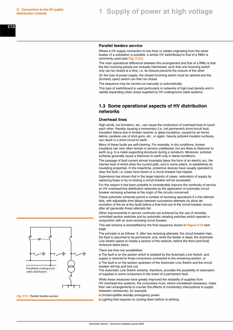
Schneider Electric - Electrical installation guide 2005
C12
C - Connection to the HV publicdistribution network
Fig. C13 : Parallel feeders service
Parallel feeders serviceWhere a HV supply connection to two lines or cables originating from the samebusbar of a substation is possible, a similar HV switchboard to that of a RMU iscommonly used (see Fig. C13 ).
The main operational difference between this arrangement and that of a RMU is thatthe two incoming panels are mutually interlocked, such that one incoming switchonly can be closed at a time, i.e. its closure prevents the closure of the other.
On the loss of power supply, the closed incoming switch must be opened and the(formerly open) switch can then be closed.
The sequence may be carried out manually or automatically.
This type of switchboard is used particularly in networks of high-load density and inrapidly-expanding urban areas supplied by HV underground cable systems.
1.3 Some operational aspects of HV distributionnetworks
Overhead linesHigh winds, ice formation, etc., can cause the conductors of overhead lines to toucheach other, thereby causing a momentary (i.e. not permanent) short-circuit fault.Insulation failure due to broken ceramic or glass insulators, caused by air-bornedebris; careless use of shot-guns, etc., or again, heavily polluted insulator surfaces,can result in a short-circuit to earth.
Many of these faults are self-clearing. For example, in dry conditions, brokeninsulators can very often remain in service undetected, but are likely to flashover toearth (e.g. to a metal supporting structure) during a rainstorm. Moreover, pollutedsurfaces generally cause a flashover to earth only in damp conditions.
The passage of fault current almost invariably takes the form of an electric arc, theintense heat of which dries the current path, and to some extent, re-establishes itsinsulating properties. In the meantime, protective devices have usually operated toclear the fault, i.e. fuses have blown or a circuit breaker has tripped.
Experience has shown that in the large majority of cases, restoration of supply byreplacing fuses or by re-closing a circuit breaker will be successful.
For this reason it has been possible to considerably improve the continuity of serviceon HV overhead-line distribution networks by the application of automatic circuitbreaker reclosing schemes at the origin of the circuits concerned.
These automatic schemes permit a number of reclosing operations if a first attemptfails, with adjustable time delays between successive attempts (to allow de-ionization of the air at the fault) before a final lock-out of the circuit breaker occurs,after all (generally three) attempts fail.
Other improvements in service continuity are achieved by the use of remotely-controlled section switches and by automatic isolating switches which operate inconjunction with an auto-reclosing circuit breaker.
This last scheme is exemplified by the final sequence shown in Figure C14 nextpage.
The principle is as follows: If, after two reclosing attempts, the circuit breaker trips,the fault is assumed to be permanent, and, while the feeder is dead, the AutomaticLine Switch opens to isolate a section of the network, before the third (and final)reclosure takes place.
There are then two possibilities:c The fault is on the section which is isolated by the Automatic Line Switch, andsupply is restored to those consumers connected to the remaining section, orc The fault is on the section upstream of the Automatic Line Switch and the circuitbreaker will trip and lock out.The Automatic Line Switch scheme, therefore, provides the possibility of restorationof supplies to some consumers in the event of a permanent fault.
While these measures have greatly improved the reliability of supplies fromHV overhead line systems, the consumers must, where considered necessary, maketheir own arrangements to counter the effects of momentary interruptions to supply(between reclosures), for example:c Uninterruptible standby emergency powerc Lighting that requires no cooling down before re-striking.
Paralleled undergroundcable distributors
1 Supply of power at high voltage
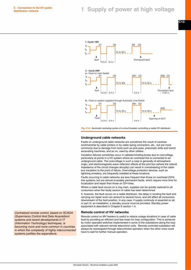
C13
Schneider Electric - Electrical installation guide 2005
C - Connection to the HV publicdistribution network 1 Supply of power at high voltage
Underground cable networksFaults on underground cable networks are sometimes the result of carelessworkmanship by cable jointers or by cable laying contractors, etc., but are morecommonly due to damage from tools such as pick-axes, pneumatic drills and trenchexcavating machines, and so on, used by other utilities.
Insulation failures sometimes occur in cableterminating boxes due to overvoltage,particularly at points in a HV system where an overhead line is connected to anunderground cable. The overvoltage in such a case is generally of atmosphericorigin, and electromagnetic-wave reflection effects at the joint box (where the naturalimpedance of the circuit changes abruptly) can result in overstressing of the cable-box insulation to the point of failure. Overvoltage protection devices, such aslightning arresters, are frequently installed at these locations.
Faults occurring in cable networks are less frequent than those on overhead (O/H)line systems, but are almost invariably permanent faults, which require more time forlocalization and repair than those on O/H lines.
Where a cable fault occurs on a ring main, supplies can be quickly restored to allconsumers when the faulty section of cable has been determined.
If, however, the fault occurs on a radial distributor, the delay in locating the fault andcarrying out repair work can amount to several hours, and will affect all consumersdownstream of the fault position. In any case, if supply continuity is essential on all,or part of, an installation, a standby source must be provided. Standby powerequipment is described in Chapter E section 1.4.
Remote control of HV networksRemote control on MV feeders is useful to reduce outage durations in case of cablefault by providing an efficient and fast mean for loop configuration. This is achievedby motor operated switches implemented in some of the substations along the loopassociated with relevant remote telecontrol units. Remote controled substation willalways be reenergized through telecontroled operation when the other ones couldhave to wait for further manual operation.
Fig. C14 : Automatic reclosing cycles of a circuit breaker controlling a radial HV distributor
IfInIo
O1 O2
O1 O2
O1 O2
fault0.3 s 0.4 s
15 to 30 s
SR O3
Permanent fault
1- Cycle 1SR
2 - Cycle 2SRa - Fault on main feeder
IfInIo
0.3 s 0.4 s
15 to 30s
SR1 O3
Permanent fault0.4 s
15 to 30 s
SR2 O4
0.45 sfault
b - Fault on section supplied through Automatic Line Switch
IfInIo
0.3 s 0.4 s
15 to 30 s
SR1 O3
0.4 s
15 to 30 sSR2
Opening of IACTFault
Centralized remote control, based on SCADA(Supervisory Control And Data Acquisition)systems and recent developments in IT(Information Technology) techniques, isbecoming more and more common in countriesin which the complexity of highly interconnectedsystems justifies the expenditure.
Schneider Electric - Electrical installation guide 2005
C14
C - Connection to the HV publicdistribution network
Large consumers of electricity are invariably supplied at HV.
On LV systems operating at 120/208 V (3-phase 4-wires), a load of 50 kVA might beconsidered to be “large”, while on a 240/415 V 3-phase system a “large” consumercould have a load in excess of 100 kVA. Both systems of LV distribution arecommon in many parts of the world.As a matter of interest, the IEC recommends a “world” standard of 230/400 V for3-phase 4-wire systems. This is a compromise level and will allow existing systemswhich operate at 220/380 V and at 240/415 V, or close to these values, to complywith the proposed standard simply by adjusting the off-circuit tapping switches ofstandard distribution transformers.
The distance over which the load has to be transmitted is a further factor inconsidering an HV or LV service. Services to small but isolated rural consumers areobvious examples.
The decision of a HV or LV supply will depend on local circumstances andconsiderations such as those mentioned above, and will generally be imposed by theutility for the district concerned.
When a decision to supply power at HV has been made, there are two widely-followed methods of proceeding:1 - The power-supplier constructs a standard substation close to the consumer’spremises, but the HV/LV transformer(s) is (are) located in transformer chamber(s)inside the premises, close to the load centre2 - The consumer constructs and equips his own substation on his own premises, towhich the power supplier makes the HV connectionIn method no. 1 the power supplier owns the substation, the cable(s) to thetransformer(s), the transformer(s) and the transformer chamber(s), to which he hasunrestricted access.The transformer chamber(s) is (are) constructed by the consumer (to plans andregulations provided by the supplier) and include plinths, oil drains, fire walls andceilings, ventilation, lighting, and earthing systems, all to be approved by the supplyauthority.The tariff structure will cover an agreed part of the expenditure required to providethe service.Whichever procedure is followed, the same principles apply in the conception andrealization of the project. The following notes refer to procedure no. 2.
2.1 Preliminary information
Before any negotiations or discussions can be initiated with the supply authorities,the following basic elements must be established:
Maximum anticipated power (kVA) demandDetermination of this parameter is described in Chapter B, and must take intoaccount the possibility of future additional load requirements. Factors to evaluate atthis stage are:c The utilization factor (ku)c The simultaneity factor (ks)
Layout plans and elevations showing location of proposed substationPlans should indicate clearly the means of access to the proposed substation, withdimensions of possible restrictions, e.g. entrances corridors and ceiling height,together with possible load (weight) bearing limits, and so on, keeping in mind that:c The power-supply personnel must have free and unrestricted access to theHV equipment in the substation at all timesc Only qualified and authorized consumer’s personnel are allowed access to thesubstationc Some supply authorities or regulations require that the part of the installation operatedby the authority is located in a separated room from the part operated by the customer.
Degree of supply continuity requiredThe consumer must estimate the consequences of a supply failure in terms of itsduration:c Loss of productionc Safety of personnel and equipment
2 Procedure for the establishmentof a new substation
The consumer must provide certain data to theutility at the earliest stage of the project.
C15
Schneider Electric - Electrical installation guide 2005
C - Connection to the HV publicdistribution network
2.2 Project studies
From the information provided by the consumer, the power-supplier must indicate:
The type of power supply proposed and definec The kind of power-supply system: overheadline or underground-cable networkc Service connection details: single-line service, ring-main installation, or parallelfeeders, etc.c Power (kVA) limit and fault current level
The nominal voltage and rated voltage(Highest voltage for equipment) Existing or future, depending on the development ofthe system.
Metering details which define:c The cost of connection to the power networkc Tariff details (consumption and standing charges)
2.3 Implementation
Before any installation work is started, the official agreement of the power-suppliermust be obtained. The request for approval must include the following information,largely based on the preliminary exchanges noted above:c Location of the proposed substationc One-line diagram of power circuits and connections, together with earthing-circuitproposalsc Full details of electrical equipment to be installed, including performancecharacteristicsc Layout of equipment and provision for metering componentsc Arrangements for power-factor improvement if eventually requiredc Arrangements provided for emergency standby power plant (HV or LV) if eventuallyrequired
2.4 Commissioning
When required by the authority, commissioning tests must be successfully completedbefore authority is given to energize the installation from the power supply system.Even if no test is required by the authority it is better to do the following verification tests:c Measurement of earth-electrode resistancesc Continuity of all equipotential earth-and safety bonding conductorsc Inspection and testing of all HV componentsc Insulation checks of HV equipmentc Dielectric strength test of transformer oil (and switchgear oil if appropriate)c Inspection and testing of the LV installation in the substation,c Checks on all interlocks (mechanical key and electrical) and on all automaticsequencesc Checks on correct protective-relay operation and settings
It is also imperative to check that all equipment is provided, such that any properlyexecuted operation can be carried out in complete safety. On receipt of thecertificate of conformity (if required):c Personnel of the power-supply authority will energize the HV equipment and checkfor correct operation of the meteringc The installation contractor is responsible for testing and connection of theLV installation
When finally the substation is operational:c The substation and all equipment belongs to the consumerc The power-supply authority has operational control over all HV switchgear in thesubstation, e.g. the two incoming load-break switches and the transformer HV switch(or CB) in the case of a RingMainUnit, together with all associated HV earthing switchesc The power-supply personnel has unrestricted access to the HV equipmentc The consumer has independent control of the HV switch (or CB) of the transformer(s)only, the consumer is responsible for the maintenance of all substation equipment,and must request the power-supply authority to isolate and earth the switchgear toallow maintenance work to proceed. The power supplier must issue a signed permit-to-work to the consumers maintenance personnel, together with keys of locked-offisolators, etc. at which the isolation has been carried out.
2 Procedure for the establishmentof a new substation
The utility must give specific information to theprospective consumer.
The utility must give official approval of theequipment to be installed in the substation,and of proposed methods of installation.
After testing and checking of the installation byan independent test authority, a certificate isgranted which permits the substation to be putinto service.
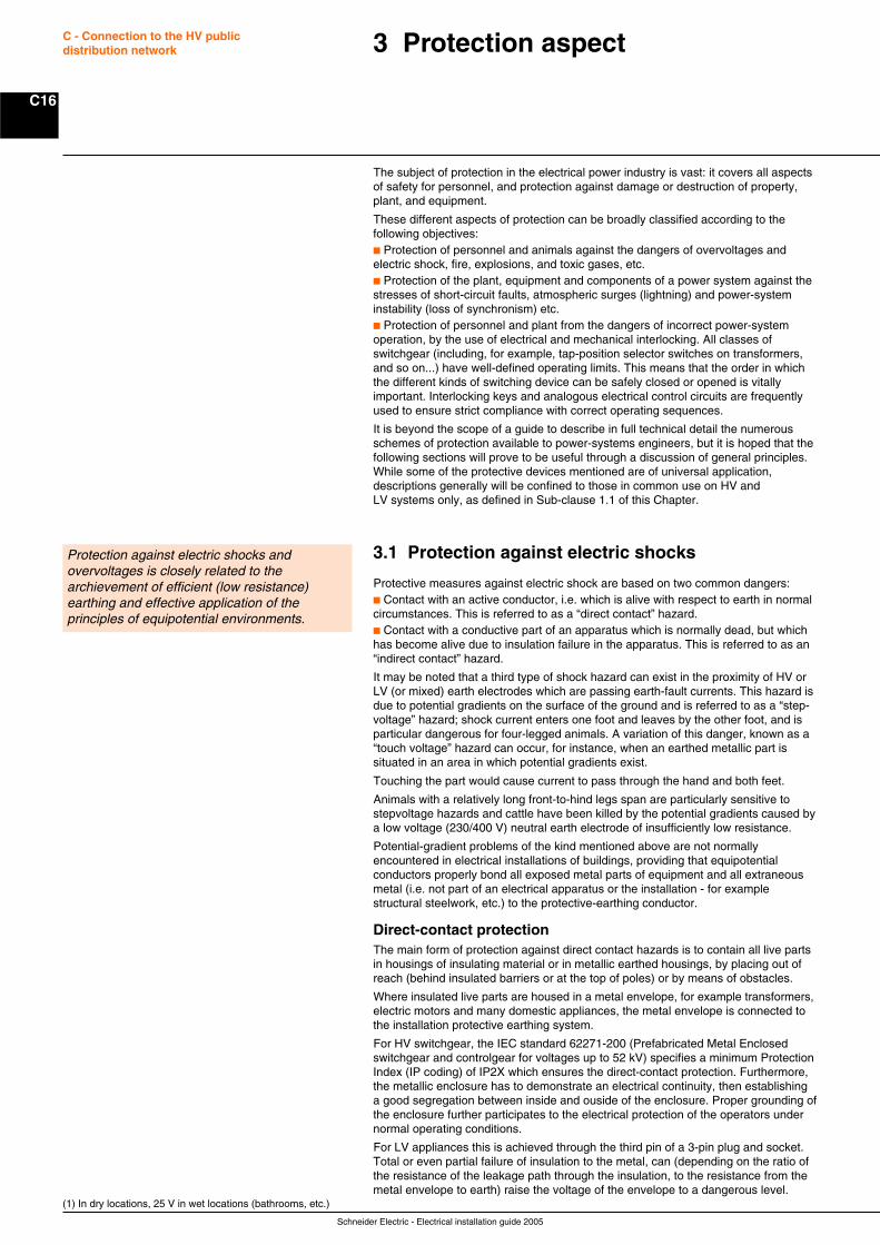
Schneider Electric - Electrical installation guide 2005
C16
C - Connection to the HV publicdistribution network 3 Protection aspect
The subject of protection in the electrical power industry is vast: it covers all aspectsof safety for personnel, and protection against damage or destruction of property,plant, and equipment.
These different aspects of protection can be broadly classified according to thefollowing objectives:c Protection of personnel and animals against the dangers of overvoltages andelectric shock, fire, explosions, and toxic gases, etc.c Protection of the plant, equipment and components of a power system against thestresses of short-circuit faults, atmospheric surges (lightning) and power-systeminstability (loss of synchronism) etc.c Protection of personnel and plant from the dangers of incorrect power-systemoperation, by the use of electrical and mechanical interlocking. All classes ofswitchgear (including, for example, tap-position selector switches on transformers,and so on...) have well-defined operating limits. This means that the order in whichthe different kinds of switching device can be safely closed or opened is vitallyimportant. Interlocking keys and analogous electrical control circuits are frequentlyused to ensure strict compliance with correct operating sequences.
It is beyond the scope of a guide to describe in full technical detail the numerousschemes of protection available to power-systems engineers, but it is hoped that thefollowing sections will prove to be useful through a discussion of general principles.While some of the protective devices mentioned are of universal application,descriptions generally will be confined to those in common use on HV andLV systems only, as defined in Sub-clause 1.1 of this Chapter.
3.1 Protection against electric shocks
Protective measures against electric shock are based on two common dangers:c Contact with an active conductor, i.e. which is alive with respect to earth in normalcircumstances. This is referred to as a “direct contact” hazard.c Contact with a conductive part of an apparatus which is normally dead, but whichhas become alive due to insulation failure in the apparatus. This is referred to as an“indirect contact” hazard.
It may be noted that a third type of shock hazard can exist in the proximity of HV orLV (or mixed) earth electrodes which are passing earth-fault currents. This hazard isdue to potential gradients on the surface of the ground and is referred to as a “step-voltage” hazard; shock current enters one foot and leaves by the other foot, and isparticular dangerous for four-legged animals. A variation of this danger, known as a“touch voltage” hazard can occur, for instance, when an earthed metallic part issituated in an area in which potential gradients exist.
Touching the part would cause current to pass through the hand and both feet.
Animals with a relatively long front-to-hind legs span are particularly sensitive tostepvoltage hazards and cattle have been killed by the potential gradients caused bya low voltage (230/400 V) neutral earth electrode of insufficiently low resistance.
Potential-gradient problems of the kind mentioned above are not normallyencountered in electrical installations of buildings, providing that equipotentialconductors properly bond all exposed metal parts of equipment and all extraneousmetal (i.e. not part of an electrical apparatus or the installation - for examplestructural steelwork, etc.) to the protective-earthing conductor.
Direct-contact protectionThe main form of protection against direct contact hazards is to contain all live partsin housings of insulating material or in metallic earthed housings, by placing out ofreach (behind insulated barriers or at the top of poles) or by means of obstacles.
Where insulated live parts are housed in a metal envelope, for example transformers,electric motors and many domestic appliances, the metal envelope is connected tothe installation protective earthing system.
For HV switchgear, the IEC standard 62271-200 (Prefabricated Metal Enclosedswitchgear and controlgear for voltages up to 52 kV) specifies a minimum ProtectionIndex (IP coding) of IP2X which ensures the direct-contact protection. Furthermore,the metallic enclosure has to demonstrate an electrical continuity, then establishinga good segregation between inside and ouside of the enclosure. Proper grounding ofthe enclosure further participates to the electrical protection of the operators undernormal operating conditions.
For LV appliances this is achieved through the third pin of a 3-pin plug and socket.Total or even partial failure of insulation to the metal, can (depending on the ratio ofthe resistance of the leakage path through the insulation, to the resistance from themetal envelope to earth) raise the voltage of the envelope to a dangerous level.
(1) In dry locations, 25 V in wet locations (bathrooms, etc.)
Protection against electric shocks andovervoltages is closely related to thearchievement of efficient (low resistance)earthing and effective application of theprinciples of equipotential environments.
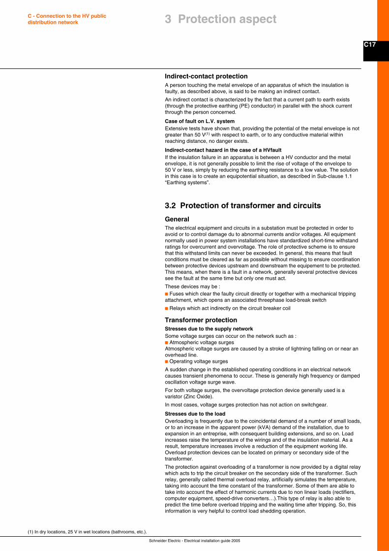
C17
Schneider Electric - Electrical installation guide 2005
C - Connection to the HV publicdistribution network
Indirect-contact protectionA person touching the metal envelope of an apparatus of which the insulation isfaulty, as described above, is said to be making an indirect contact.
An indirect contact is characterized by the fact that a current path to earth exists(through the protective earthing (PE) conductor) in parallel with the shock currentthrough the person concerned.
Case of fault on L.V. systemExtensive tests have shown that, providing the potential of the metal envelope is notgreater than 50 V(1) with respect to earth, or to any conductive material withinreaching distance, no danger exists.
Indirect-contact hazard in the case of a HVfaultIf the insulation failure in an apparatus is between a HV conductor and the metalenvelope, it is not generally possible to limit the rise of voltage of the envelope to50 V or less, simply by reducing the earthing resistance to a low value. The solutionin this case is to create an equipotential situation, as described in Sub-clause 1.1“Earthing systems”.
3.2 Protection of transformer and circuits
GeneralThe electrical equipment and circuits in a substation must be protected in order toavoid or to control damage du to abnormal currents and/or voltages. All equipmentnormally used in power system installations have standardized short-time withstandratings for overcurrent and overvoltage. The role of protective scheme is to ensurethat this withstand limits can never be exceeded. In general, this means that faultconditions must be cleared as far as possible without missing to ensure coordinationbetween protective devices upstream and downstream the equipement to be protected.This means, when there is a fault in a network, generally several protective devicessee the fault at the same time but only one must act.
These devices may be :c Fuses which clear the faulty circuit directly or together with a mechanical trippingattachment, which opens an associated threephase load-break switch
c Relays which act indirectly on the circuit breaker coil
Transformer protectionStresses due to the supply networkSome voltage surges can occur on the network such as :c Atmospheric voltage surgesAtmospheric voltage surges are caused by a stroke of lightning falling on or near anoverhead line.c Operating voltage surges
A sudden change in the established operating conditions in an electrical networkcauses transient phenomena to occur. These is generally high frequency or dampedoscillation voltage surge wave.
For both voltage surges, the overvoltage protection device generally used is avaristor (Zinc Oxide).
In most cases, voltage surges protection has not action on switchgear.
Stresses due to the loadOverloading is frequently due to the coincidental demand of a number of small loads,or to an increase in the apparent power (kVA) demand of the installation, due toexpansion in an entreprise, with consequent building extensions, and so on. Loadincreases raise the temperature of the wirings and of the insulation material. As aresult, temperature increases involve a reduction of the equipment working life.Overload protection devices can be located on primary or secondary side of thetransformer.
The protection against overloading of a transformer is now provided by a digital relaywhich acts to trip the circuit breaker on the secondary side of the transformer. Suchrelay, generally called thermal overload relay, artificially simulates the temperature,taking into account the time constant of the transformer. Some of them are able totake into account the effect of harmonic currents due to non linear loads (rectifiers,computer equipment, speed-drive converters…).This type of relay is also able topredict the time before overload tripping and the waiting time after tripping. So, thisinformation is very helpful to control load shedding operation.
(1) In dry locations, 25 V in wet locations (bathrooms, etc.).
3 Protection aspect
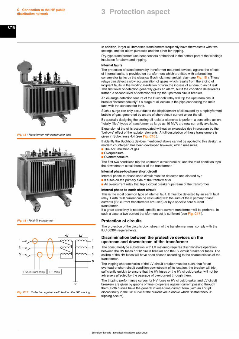
Schneider Electric - Electrical installation guide 2005
C18
C - Connection to the HV publicdistribution network
In addition, larger oil-immersed transformers frequently have thermostats with twosettings, one for alarm purposes and the other for tripping.
Dry-type transformers use heat sensors embedded in the hottest part of the windingsinsulation for alarm and tripping.
Internal faultsThe protection of transformers by transformer-mounted devices, against the effectsof internal faults, is provided on transformers which are fitted with airbreathingconservator tanks by the classical Buchholz mechanical relay (see Fig. 15 ). Theserelays can detect a slow accumulation of gases which results from the arcing ofincipient faults in the winding insulation or from the ingress of air due to an oil leak.This first level of detection generally gives an alarm, but if the condition deterioratesfurther, a second level of detection will trip the upstream circuit breaker.
An oil-surge detection feature of the Buchholz relay will trip the upstream circuitbreaker “instantaneously” if a surge of oil occurs in the pipe connecting the maintank with the conservator tank.
Such a surge can only occur due to the displacement of oil caused by a rapidlyformedbubble of gas, generated by an arc of short-circuit current under the oil.
By specially designing the cooling-oil radiator elements to perform a concertina action,“totally filled” types of transformer as large as 10 MVA are now currently available.
Expansion of the oil is accommodated without an excessive rise in pressure by the“bellows” effect of the radiator elements. A full description of these transformers isgiven in Sub-clause 4.4 (see Fig. C16 ).
Evidently the Buchholz devices mentioned above cannot be applied to this design; amodern counterpart has been developed however, which measures:c The accumulation of gasc Overpressurec Overtemperature
The first two conditions trip the upstream circuit breaker, and the third condition tripsthe downstream circuit breaker of the transformer.
Internal phase-to-phase short circuitInternal phase-to-phase short circuit must be detected and cleared by :c 3 fuses on the primary side of the tranformer orc An overcurrent relay that trip a circuit breaker upstream of the transformer
Internal phase-to-earth short circuitThis is the most common type of internal fault. It must be detected by an earth faultrelay. Earth fault current can be calculated with the sum of the 3 primary phasecurrents (if 3 current transformers are used) or by a specific core currenttransformer.If a great sensitivity is needed, specific core current transformer will be prefered. Insuch a case, a two current transformers set is sufficient (see Fig. C17 ).
Protection of circuitsThe protection of the circuits downstream of the transformer must comply with theIEC 60364 requirements.
Discrimination between the protective devices on theupstream and downstream of the transformerThe consumer-type substation with LV metering requires discriminative operationbetween the HV fuses or HV circuit breaker and the LV circuit breaker or fuses. Thecalibre of the HV fuses will have been chosen according to the characteristics of thetransformer.
The tripping characteristics of the LV circuit breaker must be such, that for anoverload or short-circuit condition downstream of its location, the breaker will tripsufficiently quickly to ensure that the HV fuses or the HV circuit breaker will not beadversely affected by the passage of overcurrent through them.
The tripping performance curves for HV fuses or HV circuit breaker and LV circuitbreakers are given by graphs of time-to-operate against current passing throughthem. Both curves have the general inverse-time/current form (with an abruptdiscontinuity in the CB curve at the current value above which “instantaneous”tripping occurs).
Fig. 16 : Total-fill transformer
Fig. 15 : Transformer with conservator tank
Fig. C17 : Protection against earth fault on the HV winding
N
3
2
1
HV LV
3
2
1
E/F relayOvercurrent relay
3 Protection aspect
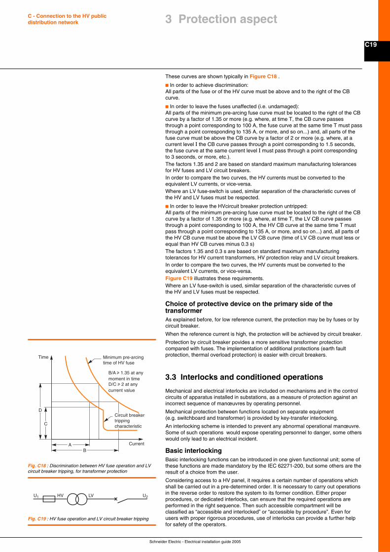
C19
Schneider Electric - Electrical installation guide 2005
C - Connection to the HV publicdistribution network
These curves are shown typically in Figure C18 .
c In order to achieve discrimination:All parts of the fuse or of the HV curve must be above and to the right of the CBcurve.
c In order to leave the fuses unaffected (i.e. undamaged):All parts of the minimum pre-arcing fuse curve must be located to the right of the CBcurve by a factor of 1.35 or more (e.g. where, at time T, the CB curve passesthrough a point corresponding to 100 A, the fuse curve at the same time T must passthrough a point corresponding to 135 A, or more, and so on...) and, all parts of thefuse curve must be above the CB curve by a factor of 2 or more (e.g. where, at acurrent level I the CB curve passes through a point corresponding to 1.5 seconds,the fuse curve at the same current level I must pass through a point correspondingto 3 seconds, or more, etc.).The factors 1.35 and 2 are based on standard maximum manufacturing tolerancesfor HV fuses and LV circuit breakers.In order to compare the two curves, the HV currents must be converted to theequivalent LV currents, or vice-versa.Where an LV fuse-switch is used, similar separation of the characteristic curves ofthe HV and LV fuses must be respected.
c In order to leave the HVcircuit breaker protection untripped:All parts of the minimum pre-arcing fuse curve must be located to the right of the CBcurve by a factor of 1.35 or more (e.g. where, at time T, the LV CB curve passesthrough a point corresponding to 100 A, the HV CB curve at the same time T mustpass through a point corresponding to 135 A, or more, and so on...) and, all parts ofthe HV CB curve must be above the LV CB curve (time of LV CB curve must less orequal than HV CB curves minus 0.3 s)The factors 1.35 and 0.3 s are based on standard maximum manufacturingtolerances for HV current transformers, HV protection relay and LV circuit breakers.In order to compare the two curves, the HV currents must be converted to theequivalent LV currents, or vice-versa.Figure C19 illustrates these requirements.Where an LV fuse-switch is used, similar separation of the characteristic curves ofthe HV and LV fuses must be respected.
Choice of protective device on the primary side of thetransformerAs explained before, for low reference current, the protection may be by fuses or bycircuit breaker.
When the reference current is high, the protection will be achieved by circuit breaker.
Protection by circuit breaker povides a more sensitive transformer protectioncompared with fuses. The implementation of additional protections (earth faultprotection, thermal overload protection) is easier with circuit breakers.
3.3 Interlocks and conditioned operations
Mechanical and electrical interlocks are included on mechanisms and in the controlcircuits of apparatus installed in substations, as a measure of protection against anincorrect sequence of manœuvres by operating personnel.
Mechanical protection between functions located on separate equipment(e.g. switchboard and transformer) is provided by key-transfer interlocking.
An interlocking scheme is intended to prevent any abnormal operational manœuvre.Some of such operations would expose operating personnel to danger, some otherswould only lead to an electrical incident.
Basic interlockingBasic interlocking functions can be introduced in one given functionnal unit; some ofthese functions are made mandatory by the IEC 62271-200, but some others are theresult of a choice from the user.
Considering access to a HV panel, it requires a certain number of operations whichshall be carried out in a pre-determined order. It is necessary to carry out operationsin the reverse order to restore the system to its former condition. Either properprocedures, or dedicated interlocks, can ensure that the required operations areperformed in the right sequence. Then such accessible compartment will beclassified as “accessible and interlocked” or “accessible by procedure”. Even forusers with proper rigorous procedures, use of interlocks can provide a further helpfor safety of the operators.
Fig. C18 : Discrimination between HV fuse operation and LVcircuit breaker tripping, for transformer protection
Fig. C19 : HV fuse operation and LV circuit breaker tripping
U1 HV LV U2
D
C
Time
AB
Current
Minimum pre-arcing time of HV fuse
Circuit breaker trippingcharacteristic
B/A u 1.35 at any moment in timeD/C u 2 at any current value
3 Protection aspect
Schneider Electric - Electrical installation guide 2005
C20
C - Connection to the HV publicdistribution network
Key interlockingBeyond the interlocks available within a given functionnal unit (see also 4.2), themost widely-used form of locking/interlocking depends on the principle of key transfer.
The principle is based on the possibility of freeing or trapping one or several keys,according to whether or not the required conditions are satisfied.
These conditions can be combined in unique and obligatory sequences, therebyguaranteeing the safety of personnel and installation by the avoidance of anincorrect operational procedure.
Non-observance of the correct sequence of operations in either case may haveextremely serious consequences for the operating personnel, as well as for theequipment concerned.
Note: It is important to provide for a scheme of interlocking in the basic design stageof planning a HV/LV substation. In this way, the apparatuses concerned will beequipped during manufacture in a coherent manner, with assured compatibility ofkeys and locking devices.
Service continuityFor a given switchboard, the definition of the accessible compartments as well as theiraccess conditions provide the basis of the “Loss of Service Continuity” classificationdefined in the standard IEC 62271-200. Use of interlocks or only proper proceduredoes not have any influence on the service continuity. Only the request for accessinga given part of the switchboard, under normal operation conditions, results in limitingconditions which can be more or less severe regarding the continuity of the electricaldistribution process.
Interlocks in substationsIn a HV/LV distribution substation which includes:c A single incoming HV panel or two incoming panels (from parallel feeders) or twoincoming/outgoing ring-main panelsc A transformer switchgear-and-protection panel, which can include a load-break/disconnecting switch with HV fuses and an earthing switch, or a circuit breaker andline disconnecting switch together with an earthing switchc A transformer compartment
Interlocks allow manœuvres and access to different panels in the following conditions:
Basic interlocks, embbeded in single functionnal unitsc Operation of the load-break/isolating switchv If the panel door is closed and the associated earthing switch is openc Operation of the line-disconnecting switch of the transformer switchgear - and -protection panelv If the door of the panel is closed, andv If the circuit breaker is open, and the earthing switch(es) is (are) openc Closure of an earthing switchv If the associated isolating switch(es) is (are) open(1)
c Access to an accessible compartment of each panel, if interlocks have beenspecifiedv If the isolating switch for the compartment is open and the earthing switch(es) forthe compartment is (are) closedc Closure of the door of each accessible compartment, if interlocks have beenspecifiedv If the earthing switch(es) for the compartment is (are) closed
Functional interlocks involving several functional units or separate equipmentc Access to the terminals of a HV/LV transformerv If the tee-off functional unit has its switch open and its earthing switch closed.According to the possibility of back-feed from the LV side, a condition on theLV main breaker can be necessary.
Practical exampleIn a consumer-type substation with LV metering, the interlocking scheme mostcommonly used is HV/LV/TR (high voltage/ low voltage/transformer).
The aim of the interlocking is:c To prevent access to the transformer compartment if the earthing switch has notbeen previously closedc To prevent the closure of the earthing switch in a transformer switchgear-and-protection panel, if the LV circuit breaker of the transformer has not been previouslylocked “open” or “withdrawn”
(1) If the earthing switch is on an incoming circuit, theassociated isolating switches are those at both ends of thecircuit, and these should be suitably interlocked. In suchsituation, the interlocking function becomes a multi-units keyinterlock.
3 Protection aspect
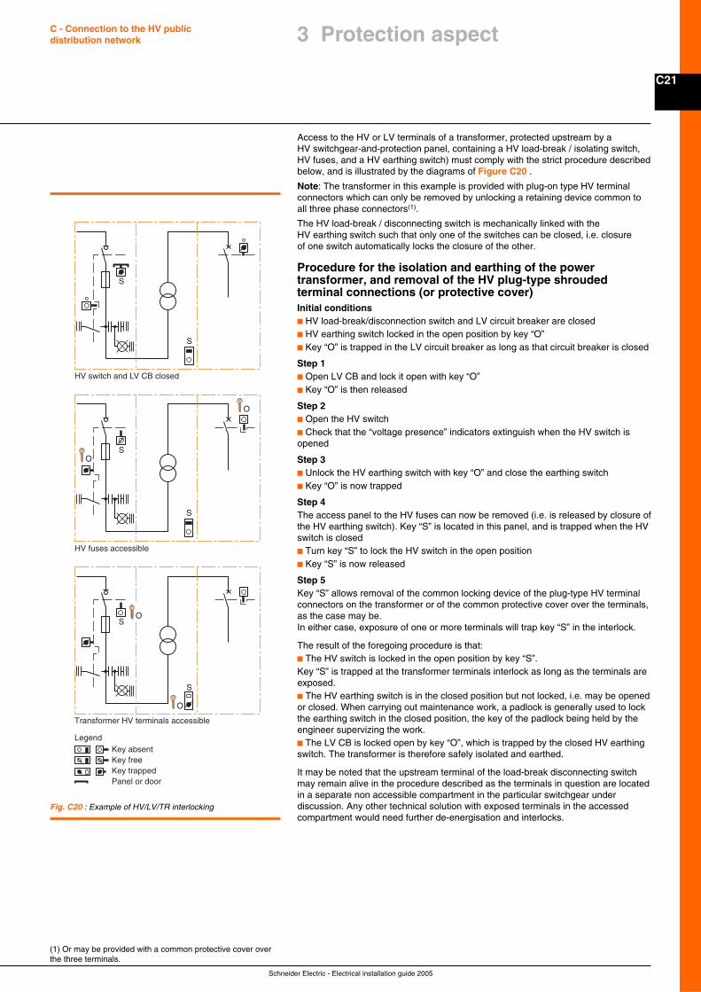
C21
Schneider Electric - Electrical installation guide 2005
C - Connection to the HV publicdistribution network
Access to the HV or LV terminals of a transformer, protected upstream by aHV switchgear-and-protection panel, containing a HV load-break / isolating switch,HV fuses, and a HV earthing switch) must comply with the strict procedure describedbelow, and is illustrated by the diagrams of Figure C20 .
Note: The transformer in this example is provided with plug-on type HV terminalconnectors which can only be removed by unlocking a retaining device common toall three phase connectors(1).
The HV load-break / disconnecting switch is mechanically linked with theHV earthing switch such that only one of the switches can be closed, i.e. closureof one switch automatically locks the closure of the other.
Procedure for the isolation and earthing of the powertransformer, and removal of the HV plug-type shroudedterminal connections (or protective cover)Initial conditionsc HV load-break/disconnection switch and LV circuit breaker are closedc HV earthing switch locked in the open position by key “O”c Key “O” is trapped in the LV circuit breaker as long as that circuit breaker is closed
Step 1c Open LV CB and lock it open with key “O”c Key “O” is then released
Step 2c Open the HV switchc Check that the “voltage presence” indicators extinguish when the HV switch isopened
Step 3c Unlock the HV earthing switch with key “O” and close the earthing switchc Key “O” is now trapped
Step 4The access panel to the HV fuses can now be removed (i.e. is released by closure ofthe HV earthing switch). Key “S” is located in this panel, and is trapped when the HVswitch is closedc Turn key “S” to lock the HV switch in the open positionc Key “S” is now released
Step 5Key “S” allows removal of the common locking device of the plug-type HV terminalconnectors on the transformer or of the common protective cover over the terminals,as the case may be.In either case, exposure of one or more terminals will trap key “S” in the interlock.
The result of the foregoing procedure is that:c The HV switch is locked in the open position by key “S”.Key “S” is trapped at the transformer terminals interlock as long as the terminals areexposed.c The HV earthing switch is in the closed position but not locked, i.e. may be openedor closed. When carrying out maintenance work, a padlock is generally used to lockthe earthing switch in the closed position, the key of the padlock being held by theengineer supervizing the work.c The LV CB is locked open by key “O”, which is trapped by the closed HV earthingswitch. The transformer is therefore safely isolated and earthed.
It may be noted that the upstream terminal of the load-break disconnecting switchmay remain alive in the procedure described as the terminals in question are locatedin a separate non accessible compartment in the particular switchgear underdiscussion. Any other technical solution with exposed terminals in the accessedcompartment would need further de-energisation and interlocks.
(1) Or may be provided with a common protective cover overthe three terminals.
Fig. C20 : Example of HV/LV/TR interlocking
S
S
S
S
S
S
Panel or door
Legend
HV switch and LV CB closed
HV fuses accessible
Transformer HV terminals accessible
Key absentKey freeKey trapped
O
O
O
O
3 Protection aspect
Schneider Electric - Electrical installation guide 2005
C22
C - Connection to the HV publicdistribution network
4.1 General
A consumer substation with LV metering is an electrical installation connected to autility supply system at a nominal voltage of 1 kV - 35 kV, and includes a singleHV/LV transformer generally not exceeding 1,250 kVA.
FunctionsThe substationAll component parts of the substation are located in one room, either in an existingbuilding, or in the form of a prefabricated housing exterior to the building.
Connection to the HV networkConnection at HV can be:c Either by a single service cable or overhead line, orc Via two mechanically interlocked load-break switches with two service cables fromduplicate supply feeders, orc Via two load-break switches of a ring-main unit
The transformerSince the use of PCB(1)-filled transformers is prohibited in most countries,the preferred available technologies are:c Oil-immersed transformers for substations located outside premisesc Dry-type, vacuum-cast-resin transformers for locations inside premises, e.g.multistoreyed buildings, buildings receiving the public, and so on...
MeteringMetering at low voltage allows the use of small metering transformers at modest cost.Most tariff structures take account of transformer losses.
LV installation circuitsA low-voltage circuit breaker, suitable for isolation duty and locking off facilities, to:c Supply a distribution boardc Protect the transformer against overloading and the downstream circuits againstshortcircuit faults.
One-line diagramsThe diagrams on the following page (see Fig. C21 ) represent the different methodsof HV service connection, which may be one of four types:c Single-line servicec Single-line service (equipped for extension to form a ring main)c Duplicate supply servicec Ring main service
4.2 Choice of panels
Standards and specificationsThe switchgear and equipments described below are rated for 1 kV - 24 kV systemsand conform to the following international standards:IEC 62271-200, 60265-1, 60694, 62271-102, 62271-105
Local regulations can also require compliance with national standards as:c France: UTEc United Kingdom: BSc Germany: VDEc United States of America: ANSI
Type of equipmentIn addition ot Ring Main Units discussed in section 1.2, all kinds of switchgeararrangements are possible when using modular compartmented panels, andprovisions for later extensions are easily realized.
Compact substations of modular panels are particularly applicable in the followingcases:c Open ring or radial networkc Severe climatic or heavily-polluted conditions (integral insulation)c Insufficient space for “classical” switchboards
This type of equipment is distinguished by its reduced dimensions, its integratedfunctions and by its operational flexibility.
4 The consumer substationwith LV metering
(1) Polychlorinated biphenyl
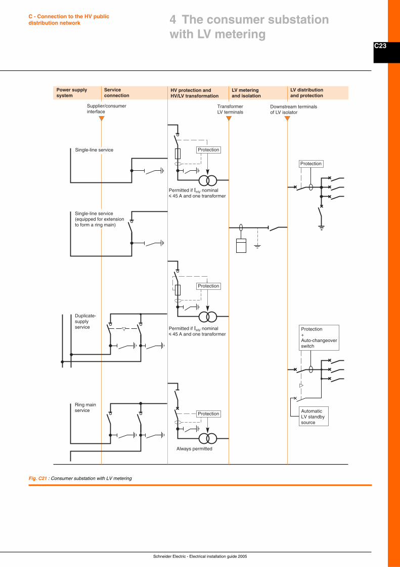
C23
Schneider Electric - Electrical installation guide 2005
C - Connection to the HV publicdistribution network
Fig. C21 : Consumer substation with LV metering
Power supply system
Service connection
HV protection andHV/LV transformation
LV meteringand isolation
LV distributionand protection
Supplier/consumer interface
Downstream terminals of LV isolator
Transformer LV terminals
Protection
Protection
Protection+Auto-changeoverswitch
Protection
Protection
Duplicate-supply service
Single-line service (equipped for extension to form a ring main)
Single-line service
Ring mainservice Automatic
LV standbysource
Permitted if IHV nominali 45 A and one transformer
Permitted if IHV nominali 45 A and one transformer
Always permitted
4 The consumer substationwith LV metering
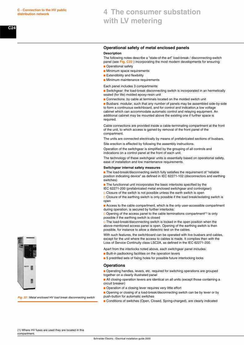
Schneider Electric - Electrical installation guide 2005
C24
C - Connection to the HV publicdistribution network
(1) Where HV fuses are used they are located in thiscompartment.
Operational safety of metal enclosed panelsDescriptionThe following notes describe a “state-of-the art” load-break / disconnecting-switchpanel (see Fig. C22 ) incorporating the most modern developments for ensuring:c Operational safetyc Minimum space requirementsc Extendibility and flexibilityc Minimum maintenance requirements
Each panel includes 3 compartments:c Switchgear: the load-break disconnecting switch is incorporated in an hermeticallysealed (for life) molded epoxy-resin unitc Connections: by cable at terminals located on the molded switch unitc Busbars: modular, such that any number of panels may be assembled side-by-sideto form a continuous switchboard, and for control and indication,a low voltagecabinet which can accommodate automatic control and relaying equipment. Anadditional cabinet may be mounted above the existing one if further space isrequired.
Cable connections are provided inside a cable-terminating compartment at the frontof the unit, to which access is gained by removal of the front panel of thecompartment.
The units are connected electrically by means of prefabricated sections of busbars.
Site erection is effected by following the assembly instructions.
Operation of the switchgear is simplified by the grouping of all controls andindications on a control panel at the front of each unit.
The technology of these switchgear units is essentially based on operational safety,ease of installation and low maintenance requirements.
Switchgear internal safety measuresc The load-break/disconnecting switch fully satisfies the requirement of “reliableposition indicating device” as defined in IEC 62271-102 (disconnectors and earthingswitches)c The functionnal unit incorporates the basic interlocks specified by theIEC 62271-200 (prefabricated metal enclosed switchgear and controlgear):v Closure of the switch is not possible unless the earth switch is openv Closure of the earthing switch is only possible if the load break/isolating switch isopenc Access to the cable compartment, which is the only user-accessible compartmentduring operation, is secured by further interlocks:v Opening of the access panel to the cable terminations compartment(1) is onlypossible if the earthing switch is closedv The load-break/disconnecting switch is locked in the open position when theabove-mentioned access panel is open. Opening of the earthing switch is thenpossible, for instance to allow a dielectric test on the cables.
With such features, the switchboard can be operated with live busbars and cables,except for the unit where the access to cables is made. It complies then with theLoss of Service Continuity class LSC2A, as defined in the IEC 62271-200.
Apart from the interlocks noted above, each switchgear panel includes:c Built-in padlocking facilities on the operation leversc 5 predrilled sets of fixing holes for possible future interlocking locks
Operationsc Operating handles, levers, etc. required for switching operations are groupedtogether on a clearly illustrated panelc All closing-operation levers are identical on all units (except those containing acircuit breaker)c Operation of a closing lever requires very little effortc Opening or closing of a load-break/disconnecting switch can be by lever or bypush-button for automatic switchesc Conditions of switches (Open, Closed, Spring-charged), are clearly indicated
Fig. 22 : Metal enclosed HV load break disconnecting switch
4 The consumer substationwith LV metering
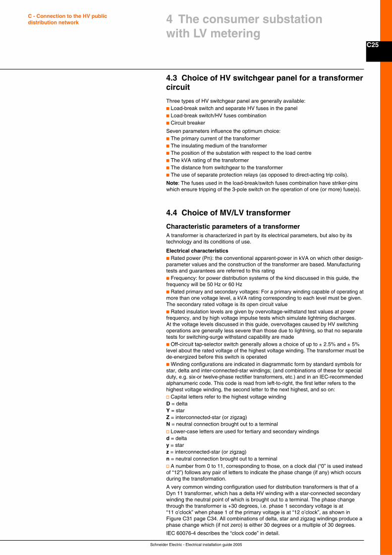
C25
Schneider Electric - Electrical installation guide 2005
C - Connection to the HV publicdistribution network
4.3 Choice of HV switchgear panel for a transformercircuit
Three types of HV switchgear panel are generally available:c Load-break switch and separate HV fuses in the panelc Load-break switch/HV fuses combinationc Circuit breaker
Seven parameters influence the optimum choice:c The primary current of the transformerc The insulating medium of the transformerc The position of the substation with respect to the load centrec The kVA rating of the transformerc The distance from switchgear to the transformerc The use of separate protection relays (as opposed to direct-acting trip coils).
Note: The fuses used in the load-break/switch fuses combination have striker-pinswhich ensure tripping of the 3-pole switch on the operation of one (or more) fuse(s).
4.4 Choice of MV/LV transformer
Characteristic parameters of a transformerA transformer is characterized in part by its electrical parameters, but also by itstechnology and its conditions of use.
Electrical characteristicsc Rated power (Pn): the conventional apparent-power in kVA on which other design-parameter values and the construction of the transformer are based. Manufacturingtests and guarantees are referred to this ratingc Frequency: for power distribution systems of the kind discussed in this guide, thefrequency will be 50 Hz or 60 Hzc Rated primary and secondary voltages: For a primary winding capable of operating atmore than one voltage level, a kVA rating corresponding to each level must be given.The secondary rated voltage is its open circuit valuec Rated insulation levels are given by overvoltage-withstand test values at powerfrequency, and by high voltage impulse tests which simulate lightning discharges.At the voltage levels discussed in this guide, overvoltages caused by HV switchingoperations are generally less severe than those due to lightning, so that no separatetests for switching-surge withstand capability are madec Off-circuit tap-selector switch generally allows a choice of up to ± 2.5% and ± 5%level about the rated voltage of the highest voltage winding. The transformer must bede-energized before this switch is operatedc Winding configurations are indicated in diagrammatic form by standard symbols forstar, delta and inter-connected-star windings; (and combinations of these for specialduty, e.g. six-or twelve-phase rectifier transformers, etc.) and in an IEC-recommendedalphanumeric code. This code is read from left-to-right, the first letter refers to thehighest voltage winding, the second letter to the next highest, and so on:v Capital letters refer to the highest voltage windingD = deltaY = starZ = interconnected-star (or zigzag)N = neutral connection brought out to a terminalv Lower-case letters are used for tertiary and secondary windingsd = deltay = starz = interconnected-star (or zigzag)n = neutral connection brought out to a terminalv A number from 0 to 11, corresponding to those, on a clock dial (“0” is used insteadof “12”) follows any pair of letters to indicate the phase change (if any) which occursduring the transformation.
A very common winding configuration used for distribution transformers is that of aDyn 11 transformer, which has a delta HV winding with a star-connected secondarywinding the neutral point of which is brought out to a terminal. The phase changethrough the transformer is +30 degrees, i.e. phase 1 secondary voltage is at“11 o’clock” when phase 1 of the primary voltage is at “12 o’clock”, as shown inFigure C31 page C34. All combinations of delta, star and zigzag windings produce aphase change which (if not zero) is either 30 degrees or a multiple of 30 degrees.
IEC 60076-4 describes the “clock code” in detail.
4 The consumer substationwith LV metering
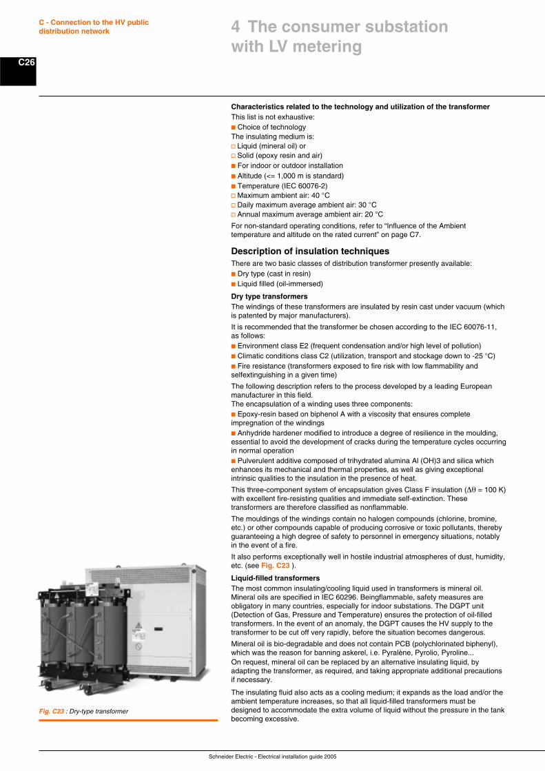
Schneider Electric - Electrical installation guide 2005
C26
C - Connection to the HV publicdistribution network
Characteristics related to the technology and utilization of the transformerThis list is not exhaustive:c Choice of technologyThe insulating medium is:v Liquid (mineral oil) orv Solid (epoxy resin and air)c For indoor or outdoor installationc Altitude (<= 1,000 m is standard)c Temperature (IEC 60076-2)v Maximum ambient air: 40 °Cv Daily maximum average ambient air: 30 °Cv Annual maximum average ambient air: 20 °C
For non-standard operating conditions, refer to “Influence of the Ambienttemperature and altitude on the rated current” on page C7.
Description of insulation techniquesThere are two basic classes of distribution transformer presently available:c Dry type (cast in resin)c Liquid filled (oil-immersed)
Dry type transformersThe windings of these transformers are insulated by resin cast under vacuum (whichis patented by major manufacturers).
It is recommended that the transformer be chosen according to the IEC 60076-11,as follows:c Environment class E2 (frequent condensation and/or high level of pollution)c Climatic conditions class C2 (utilization, transport and stockage down to -25 °C)c Fire resistance (transformers exposed to fire risk with low flammability andselfextinguishing in a given time)
The following description refers to the process developed by a leading Europeanmanufacturer in this field.The encapsulation of a winding uses three components:c Epoxy-resin based on biphenol A with a viscosity that ensures completeimpregnation of the windingsc Anhydride hardener modified to introduce a degree of resilience in the moulding,essential to avoid the development of cracks during the temperature cycles occurringin normal operationc Pulverulent additive composed of trihydrated alumina Al (OH)3 and silica whichenhances its mechanical and thermal properties, as well as giving exceptionalintrinsic qualities to the insulation in the presence of heat.
This three-component system of encapsulation gives Class F insulation (∆θ = 100 K)with excellent fire-resisting qualities and immediate self-extinction. Thesetransformers are therefore classified as nonflammable.
The mouldings of the windings contain no halogen compounds (chlorine, bromine,etc.) or other compounds capable of producing corrosive or toxic pollutants, therebyguaranteeing a high degree of safety to personnel in emergency situations, notablyin the event of a fire.
It also performs exceptionally well in hostile industrial atmospheres of dust, humidity,etc. (see Fig. C23 ).
Liquid-filled transformersThe most common insulating/cooling liquid used in transformers is mineral oil.Mineral oils are specified in IEC 60296. Beingflammable, safety measures areobligatory in many countries, especially for indoor substations. The DGPT unit(Detection of Gas, Pressure and Temperature) ensures the protection of oil-filledtransformers. In the event of an anomaly, the DGPT causes the HV supply to thetransformer to be cut off very rapidly, before the situation becomes dangerous.
Mineral oil is bio-degradable and does not contain PCB (polychlorinated biphenyl),which was the reason for banning askerel, i.e. Pyralène, Pyrolio, Pyroline...On request, mineral oil can be replaced by an alternative insulating liquid, byadapting the transformer, as required, and taking appropriate additional precautionsif necessary.
The insulating fluid also acts as a cooling medium; it expands as the load and/or theambient temperature increases, so that all liquid-filled transformers must bedesigned to accommodate the extra volume of liquid without the pressure in the tankbecoming excessive.
Fig. C23 : Dry-type transformer
4 The consumer substationwith LV metering
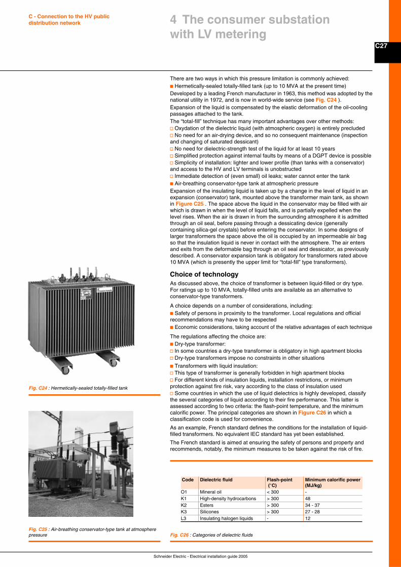
C27
Schneider Electric - Electrical installation guide 2005
C - Connection to the HV publicdistribution network
There are two ways in which this pressure limitation is commonly achieved:c Hermetically-sealed totally-filled tank (up to 10 MVA at the present time)Developed by a leading French manufacturer in 1963, this method was adopted by thenational utility in 1972, and is now in world-wide service (see Fig. C24 ).Expansion of the liquid is compensated by the elastic deformation of the oil-coolingpassages attached to the tank.The “total-fill” technique has many important advantages over other methods:v Oxydation of the dielectric liquid (with atmospheric oxygen) is entirely precludedv No need for an air-drying device, and so no consequent maintenance (inspectionand changing of saturated dessicant)v No need for dielectric-strength test of the liquid for at least 10 yearsv Simplified protection against internal faults by means of a DGPT device is possiblev Simplicity of installation: lighter and lower profile (than tanks with a conservator)and access to the HV and LV terminals is unobstructedv Immediate detection of (even small) oil leaks; water cannot enter the tankc Air-breathing conservator-type tank at atmospheric pressureExpansion of the insulating liquid is taken up by a change in the level of liquid in anexpansion (conservator) tank, mounted above the transformer main tank, as shownin Figure C25 . The space above the liquid in the conservator may be filled with airwhich is drawn in when the level of liquid falls, and is partially expelled when thelevel rises. When the air is drawn in from the surrounding atmosphere it is admittedthrough an oil seal, before passing through a dessicating device (generallycontaining silica-gel crystals) before entering the conservator. In some designs oflarger transformers the space above the oil is occupied by an impermeable air bagso that the insulation liquid is never in contact with the atmosphere. The air entersand exits from the deformable bag through an oil seal and dessicator, as previouslydescribed. A conservator expansion tank is obligatory for transformers rated above10 MVA (which is presently the upper limit for “total-fill” type transformers).
Choice of technologyAs discussed above, the choice of transformer is between liquid-filled or dry type.For ratings up to 10 MVA, totally-filled units are available as an alternative toconservator-type transformers.
A choice depends on a number of considerations, including:c Safety of persons in proximity to the transformer. Local regulations and officialrecommendations may have to be respectedc Economic considerations, taking account of the relative advantages of each technique
The regulations affecting the choice are:c Dry-type transformer:v In some countries a dry-type transformer is obligatory in high apartment blocksv Dry-type transformers impose no constraints in other situations
c Transformers with liquid insulation:v This type of transformer is generally forbidden in high apartment blocksv For different kinds of insulation liquids, installation restrictions, or minimumprotection against fire risk, vary according to the class of insulation usedv Some countries in which the use of liquid dielectrics is highly developed, classifythe several categories of liquid according to their fire performance. This latter isassessed according to two criteria: the flash-point temperature, and the minimumcalorific power. The principal categories are shown in Figure C26 in which aclassification code is used for convenience.
As an example, French standard defines the conditions for the installation of liquid-filled transformers. No equivalent IEC standard has yet been established.
The French standard is aimed at ensuring the safety of persons and property andrecommends, notably, the minimum measures to be taken against the risk of fire.
Fig. C25 : Air-breathing conservator-type tank at atmospherepressure
Fig. C24 : Hermetically-sealed totally-filled tank
Fig. C26 : Categories of dielectric fluids
Code Dielectric fluid Flash-point Minimum calorific power (°C) (MJ/kg)
O1 Mineral oil < 300 -K1 High-density hydrocarbons > 300 48K2 Esters > 300 34 - 37K3 Silicones > 300 27 - 28L3 Insulating halogen liquids - 12
4 The consumer substationwith LV metering
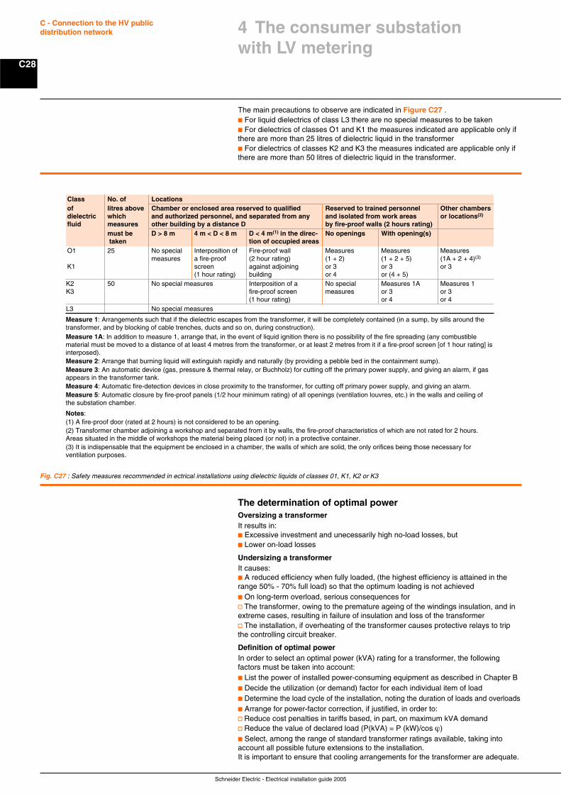
Schneider Electric - Electrical installation guide 2005
C28
C - Connection to the HV publicdistribution network
The main precautions to observe are indicated in Figure C27 .c For liquid dielectrics of class L3 there are no special measures to be takenc For dielectrics of classes O1 and K1 the measures indicated are applicable only ifthere are more than 25 litres of dielectric liquid in the transformerc For dielectrics of classes K2 and K3 the measures indicated are applicable only ifthere are more than 50 litres of dielectric liquid in the transformer.
The determination of optimal powerOversizing a transformerIt results in:c Excessive investment and unecessarily high no-load losses, butc Lower on-load losses
Undersizing a transformerIt causes:c A reduced efficiency when fully loaded, (the highest efficiency is attained in therange 50% - 70% full load) so that the optimum loading is not achievedc On long-term overload, serious consequences forv The transformer, owing to the premature ageing of the windings insulation, and inextreme cases, resulting in failure of insulation and loss of the transformerv The installation, if overheating of the transformer causes protective relays to tripthe controlling circuit breaker.
Definition of optimal powerIn order to select an optimal power (kVA) rating for a transformer, the followingfactors must be taken into account:c List the power of installed power-consuming equipment as described in Chapter Bc Decide the utilization (or demand) factor for each individual item of loadc Determine the load cycle of the installation, noting the duration of loads and overloadsc Arrange for power-factor correction, if justified, in order to:v Reduce cost penalties in tariffs based, in part, on maximum kVA demandv Reduce the value of declared load (P(kVA) = P (kW)/cos ϕ)c Select, among the range of standard transformer ratings available, taking intoaccount all possible future extensions to the installation.It is important to ensure that cooling arrangements for the transformer are adequate.
Class No. of Locationsof litres above Chamber or enclosed area reserved to qualified Reserved to trained personnel Other chambersdielectric which and authorized personnel, and separated from any and isolated from work areas or locations(2)
fluid measures other building by a distance D by fire-proof walls (2 hours rating)must be D > 8 m 4 m < D < 8 m D < 4 m(1) in the direc- No openings With opening(s) taken tion of occupied areas
O1 25 No special Interposition of Fire-proof wall Measures Measures Measuresmeasures a fire-proof (2 hour rating) (1 + 2) (1 + 2 + 5) (1A + 2 + 4)(3)
K1 screen against adjoining or 3 or 3 or 3(1 hour rating) building or 4 or (4 + 5)
K2 50 No special measures Interposition of a No special Measures 1A Measures 1K3 fire-proof screen measures or 3 or 3
(1 hour rating) or 4 or 4L3 No special measures
Measure 1: Arrangements such that if the dielectric escapes from the transformer, it will be completely contained (in a sump, by sills around thetransformer, and by blocking of cable trenches, ducts and so on, during construction).Measure 1A: In addition to measure 1, arrange that, in the event of liquid ignition there is no possibility of the fire spreading (any combustiblematerial must be moved to a distance of at least 4 metres from the transformer, or at least 2 metres from it if a fire-proof screen [of 1 hour rating] isinterposed).Measure 2: Arrange that burning liquid will extinguish rapidly and naturally (by providing a pebble bed in the containment sump).Measure 3: An automatic device (gas, pressure & thermal relay, or Buchholz) for cutting off the primary power supply, and giving an alarm, if gasappears in the transformer tank.Measure 4: Automatic fire-detection devices in close proximity to the transformer, for cutting off primary power supply, and giving an alarm.Measure 5: Automatic closure by fire-proof panels (1/2 hour minimum rating) of all openings (ventilation louvres, etc.) in the walls and ceiling ofthe substation chamber.
Notes:(1) A fire-proof door (rated at 2 hours) is not considered to be an opening.(2) Transformer chamber adjoining a workshop and separated from it by walls, the fire-proof characteristics of which are not rated for 2 hours.Areas situated in the middle of workshops the material being placed (or not) in a protective container.(3) It is indispensable that the equipment be enclosed in a chamber, the walls of which are solid, the only orifices being those necessary forventilation purposes.
Fig. C27 : Safety measures recommended in ectrical installations using dielectric liquids of classes 01, K1, K2 or K3
4 The consumer substationwith LV metering
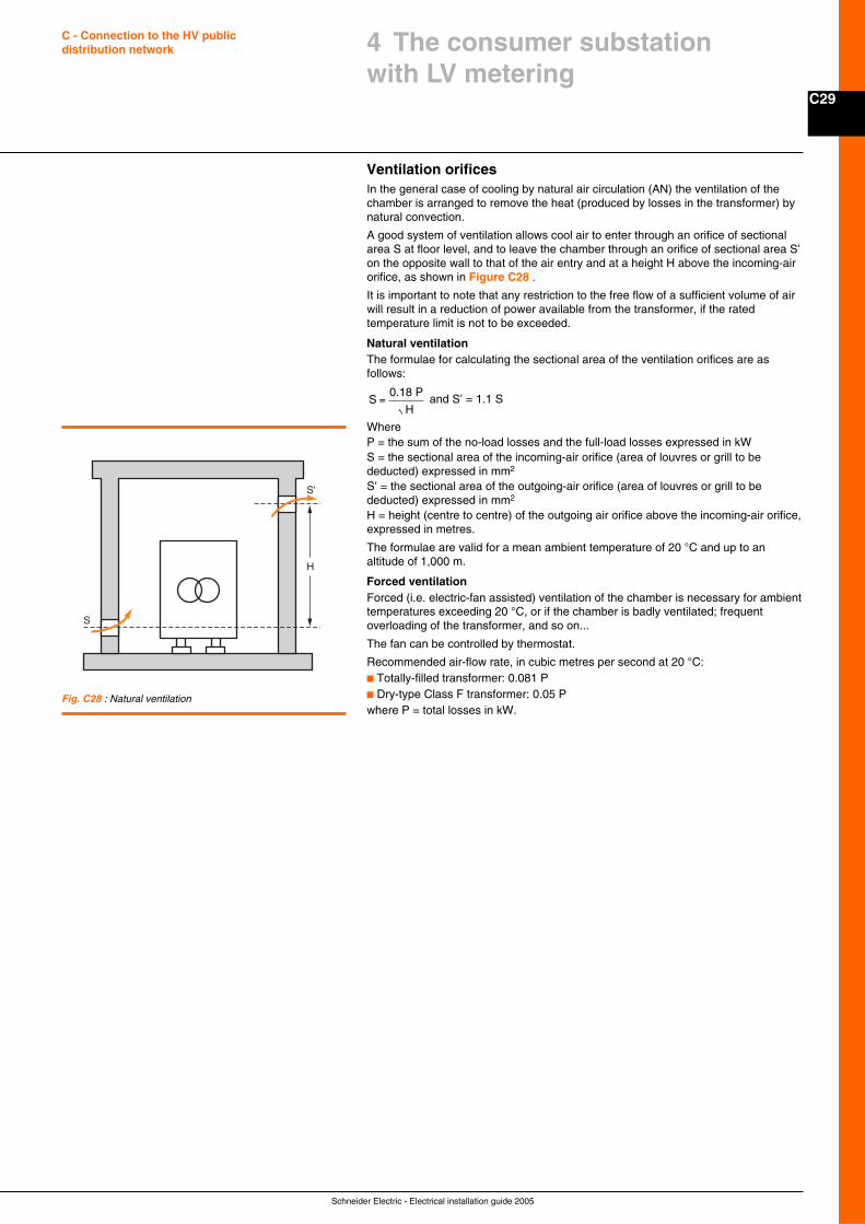
C29
Schneider Electric - Electrical installation guide 2005
C - Connection to the HV publicdistribution network
Ventilation orificesIn the general case of cooling by natural air circulation (AN) the ventilation of thechamber is arranged to remove the heat (produced by losses in the transformer) bynatural convection.
A good system of ventilation allows cool air to enter through an orifice of sectionalarea S at floor level, and to leave the chamber through an orifice of sectional area S’on the opposite wall to that of the air entry and at a height H above the incoming-airorifice, as shown in Figure C28 .
It is important to note that any restriction to the free flow of a sufficient volume of airwill result in a reduction of power available from the transformer, if the ratedtemperature limit is not to be exceeded.
Natural ventilationThe formulae for calculating the sectional area of the ventilation orifices are asfollows:
S =0.18 P
H and S’ = 1.1 S
WhereP = the sum of the no-load losses and the full-load losses expressed in kWS = the sectional area of the incoming-air orifice (area of louvres or grill to bededucted) expressed in mm2
S’ = the sectional area of the outgoing-air orifice (area of louvres or grill to bededucted) expressed in mm2
H = height (centre to centre) of the outgoing air orifice above the incoming-air orifice,expressed in metres.
The formulae are valid for a mean ambient temperature of 20 °C and up to analtitude of 1,000 m.
Forced ventilationForced (i.e. electric-fan assisted) ventilation of the chamber is necessary for ambienttemperatures exceeding 20 °C, or if the chamber is badly ventilated; frequentoverloading of the transformer, and so on...
The fan can be controlled by thermostat.
Recommended air-flow rate, in cubic metres per second at 20 °C:c Totally-filled transformer: 0.081 Pc Dry-type Class F transformer: 0.05 Pwhere P = total losses in kW.
4 The consumer substationwith LV metering
Fig. C28 : Natural ventilation
S'
S
H
Schneider Electric - Electrical installation guide 2005
C30
C - Connection to the HV publicdistribution network
5.1 General
FunctionsThe substation
According to the complexity of the installation and the manner in which the load isdivided, the substation:c Might include one room containing the HV switchboard and metering panel(s),together with the transformer(s) and low-voltage main distribution board(s),c Or might supply one or more transformer rooms, which include local LV distributionboards, supplied at HV from switchgear in a main substation, similar to thatdescribed above.
These substations may be installed, either:c Inside a building, orc Outdoors in prefabricated housings.
Connection to the HV networkConnection at HV can be:c Either by a single service cable or overhead line, orc Via two mechanically interlocked load-break switches with two service cables fromduplicate supply feeders, orc Via two load-break switches of a ring-main unit.
MeteringBefore the installation project begins, the agreement of the power-supply utilityregarding metering arrangements must be obtained.
A metering panel will be incorporated in the HV switchboard. Voltage transformersand current transformers, having the necessary metering accuracy, may be includedin the main incoming circuit breaker panel or (in the case of the voltage transformer)may be installed separately in the metering panel.
Transformer roomsIf the installation includes a number of transformer rooms, HV supplies from the mainsubstation may be by simple radial feeders connected directly to the transformers, orby duplicate feeders to each room, or again, by a ring-main, according to the degreeof supply availability desired.
In the two latter cases, 3-panel ring-main units will be required at each transformerroom.
Local emergency generatorsEmergency standby generators are intended to maintain a power supply to essentialloads, in the event of failure of the power supply system.
CapacitorsCapacitors will be installed, according to requirements:c In stepped HV banks at the main substation, orc At LV in transformer rooms.
TransformersFor additional supply-security reasons, transformers may be arranged for automaticchangeover operation, or for parallel operation.
One-line diagramsThe diagrams shown in Figure C29 next page represent:c The different methods of HV service connection, which may be one of four types:v Single-line servicev Single-line service (equipped for extension to form a ring main)v Duplicate supply servicev Ring main servicec General protection at HV, and HV metering functionsc Protection of outgoing HV circuitsc Protection of LV distribution circuits
5 The consumer substationwith HV metering
A consumer substation with HV metering is anelectrical installation connected to a utilitysupply system at a nominal voltage of 1 kV -35 kV and generally includes a single HV/LV transformer which exceeds 1,250 kVA,or several smaller transformers.The rated current of the HV switchgear doesnot normally exceed 400 A.
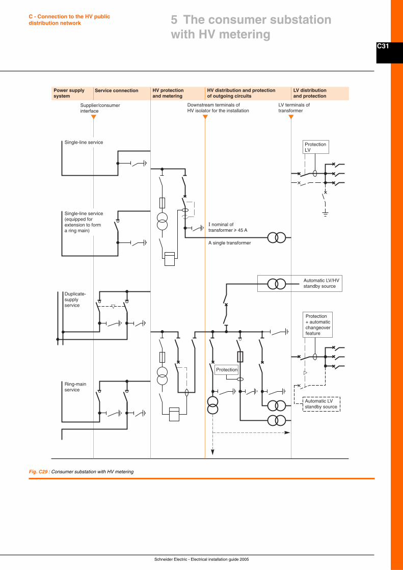
C31
Schneider Electric - Electrical installation guide 2005
C - Connection to the HV publicdistribution network
Power supplysystem
Service connection HV protectionand metering
HV distribution and protectionof outgoing circuits
LV distributionand protection
Supplier/consumerinterface
Downstream terminals of HV isolator for the installation
LV terminals oftransformer
Duplicate-supplyservice
Ring-mainservice
Single-line service(equipped for extension to form a ring main)
Protection+ automaticchangeoverfeature
Automatic LVstandby source
Protection
ProtectionLV
Automatic LV/HVstandby source
I nominal of transformer u 45 A
A single transformer
Single-line service
Fig. C29 : Consumer substation with HV metering
5 The consumer substationwith HV metering
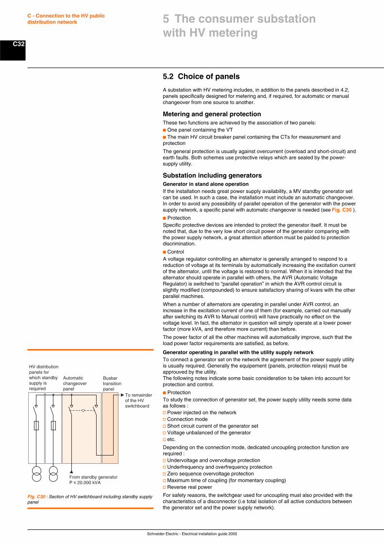
Schneider Electric - Electrical installation guide 2005
C32
C - Connection to the HV publicdistribution network
5.2 Choice of panels
A substation with HV metering includes, in addition to the panels described in 4.2,panels specifically designed for metering and, if required, for automatic or manualchangeover from one source to another.
Metering and general protectionThese two functions are achieved by the association of two panels:c One panel containing the VTc The main HV circuit breaker panel containing the CTs for measurement andprotection
The general protection is usually against overcurrent (overload and short-circuit) andearth faults. Both schemes use protective relays which are sealed by the power-supply utility.
Substation including generatorsGenerator in stand alone operationIf the installation needs great power supply availability, a MV standby generator setcan be used. In such a case, the installation must include an automatic changeover.In order to avoid any posssibility of parallel operation of the generator with the powersupply network, a specific panel with automatic changeover is needed (see Fig. C30 ).
c ProtectionSpecific protective devices are intended to protect the generator itself. It must benoted that, due to the very low short circuit power of the generator comparing withthe power supply network, a great attention attention must be paided to protectiondiscrimination.
c ControlA voltage regulator controlling an alternator is generally arranged to respond to areduction of voltage at its terminals by automatically increasing the excitation currentof the alternator, until the voltage is restored to normal. When it is intended that thealternator should operate in parallel with others, the AVR (Automatic VoltageRegulator) is switched to “parallel operation” in which the AVR control circuit isslightly modified (compounded) to ensure satisfactory sharing of kvars with the otherparallel machines.
When a number of alternators are operating in parallel under AVR control, anincrease in the excitation current of one of them (for example, carried out manuallyafter switching its AVR to Manual control) will have practically no effect on thevoltage level. In fact, the alternator in question will simply operate at a lower powerfactor (more kVA, and therefore more current) than before.
The power factor of all the other machines will automatically improve, such that theload power factor requirements are satisfied, as before.
Generator operating in parallel with the utility supply networkTo connect a generator set on the network the agreement of the power supply utilityis usually required. Generally the equipement (panels, protection relays) must beapprouved by the utility.The following notes indicate some basic consideration to be taken into account forprotection and control.
c ProtectionTo study the connection of generator set, the power supply utility needs some dataas follows :v Power injected on the networkv Connection modev Short circuit current of the generator setv Voltage unbalanced of the generatorv etc.
Depending on the connection mode, dedicated uncoupling protection function arerequired :v Undervoltage and overvoltage protectionv Underfrequency and overfrequency protectionv Zero sequence overvoltage protectionv Maximum time of coupling (for momentary coupling)v Reverse real power
For safety reasons, the switchgear used for uncoupling must also provided with thecharacteristics of a disconnector (i.e total isolation of all active conductors betweenthe generator set and the power supply network).
Fig. C30 : Section of HV switchboard including standby supplypanel
From standby generator P i 20,000 kVA
HV distribution panels for which standby supply is required
Automaticchangeoverpanel
Busbartransitionpanel
To remainder of the HV switchboard
5 The consumer substationwith HV metering
C33
Schneider Electric - Electrical installation guide 2005
C - Connection to the HV publicdistribution network
c ControlWhen generators at a consumer’s substation operate in parallel with all thegeneration of the utility power supply system, supposing the power system voltage isreduced for operational reasons (it is common to operate HV systems within a rangeof ± 5% of nominal voltage, or even more, where load-flow patterns require it).
An AVR set to maintain the voltage within ± 3% (for example) will immediatelyattempt to raise the voltage by increasing the excitation current of the alternator.
Instead of raising the voltage, the alternator will simply operate at a lower powerfactor than before, thereby increasing its current output, and will continue to do so,until it is eventually tripped out by its overcurrent protective relays. This is a well-known problem and is usually overcome by the provision of a “constant power-factor” control switch on the AVR unit.
By making this selection, the AVR will automatically adjust the excitation current tomatch whatever voltage exists on the power system, while at the same timemaintaining the power factor of the alternator constant at the pre-set value (selectedon the AVR control unit).
In the event that the alternator becomes decoupled from the power system, the AVRmust be automatically (rapidly) switched back to “constant-voltage” control.
5.3 Paralell operation of transformers
The need for operation of two or more transformers in parallel often arises due to:c Load growth, which exceeds the capactiy of an existing transformerc Lack of space (height) for one large transformerc A measure of security (the probability of two transformers failing at the same timeis very small)c The adoption of a standard size of transformer throughout an installation
Total power (kVA)The total power (kVA) available when two or more transformers of the samekVA rating are connected in parallel, is equal to the sum of the individual ratings,providing that the percentage impedances are all equal and the voltage ratios areidentical.
Transformers of unequal kVA ratings will share a load practically (but not exactly) inproportion to their ratings, providing that the voltage ratios are identical and the per-centage impedances (at their own kVA rating) are identical, or very nearly so. Inthese cases, a total of more than 90% of the sum of the two ratings is normallyavailable.
It is recommended that transformers, the kVA ratings of which differ by morethan 2:1, should not be operated permanently in parallel.
Conditions necessary for parallel operationAll paralleled units must be supplied from the same network.
The inevitable circulating currents exchanged between the secondary circuits ofparalleled transformers will be negligibly small providing that:c Secondary cabling from the transformers to the point of paralleling haveapproximately equal lengths and characteristicsc The transformer manufacturer is fully informed of the duty intended for thetransformers, so that:v The winding configurations (star, delta, zigzag star) of the several transformershave the same phase change between primary and secondary voltagesv The short-circuit impedances are equal, or differ by less than 10%v Voltage differences between corresponding phases must not exceed 0.4%v All possible information on the conditions of use, expected load cycles, etc. shouldbe given to the manufacturer with a view to optimizing load and no-load losses
5 The consumer substationwith HV metering
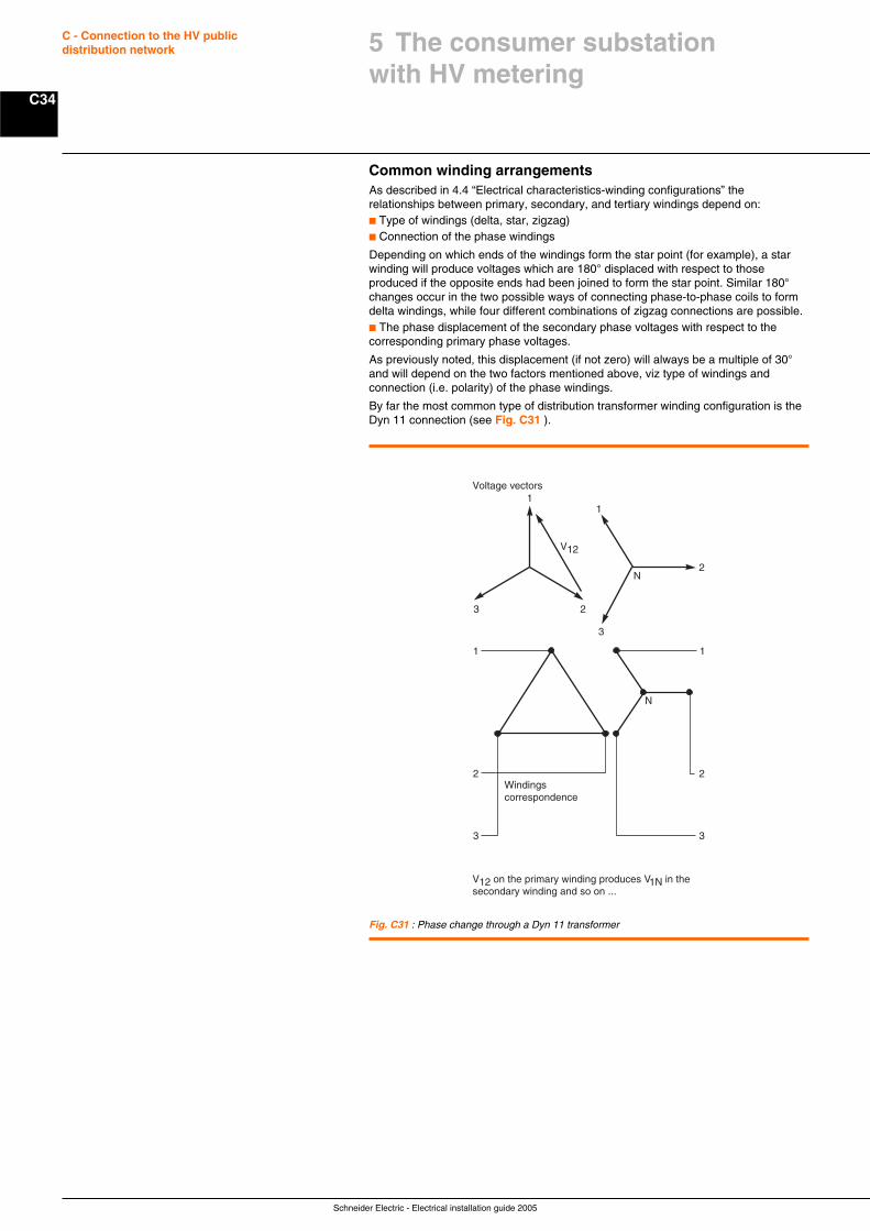
Schneider Electric - Electrical installation guide 2005
C34
C - Connection to the HV publicdistribution network
Common winding arrangementsAs described in 4.4 “Electrical characteristics-winding configurations” therelationships between primary, secondary, and tertiary windings depend on:c Type of windings (delta, star, zigzag)c Connection of the phase windings
Depending on which ends of the windings form the star point (for example), a starwinding will produce voltages which are 180° displaced with respect to thoseproduced if the opposite ends had been joined to form the star point. Similar 180°changes occur in the two possible ways of connecting phase-to-phase coils to formdelta windings, while four different combinations of zigzag connections are possible.c The phase displacement of the secondary phase voltages with respect to thecorresponding primary phase voltages.
As previously noted, this displacement (if not zero) will always be a multiple of 30°and will depend on the two factors mentioned above, viz type of windings andconnection (i.e. polarity) of the phase windings.
By far the most common type of distribution transformer winding configuration is theDyn 11 connection (see Fig. C31 ).
Fig. C31 : Phase change through a Dyn 11 transformer
1
23
V12
1
2
3
N
1
2
3
Voltage vectors
V12 on the primary winding produces V1N in the secondary winding and so on ...
Windingscorrespondence
1
2
3
N
5 The consumer substationwith HV metering
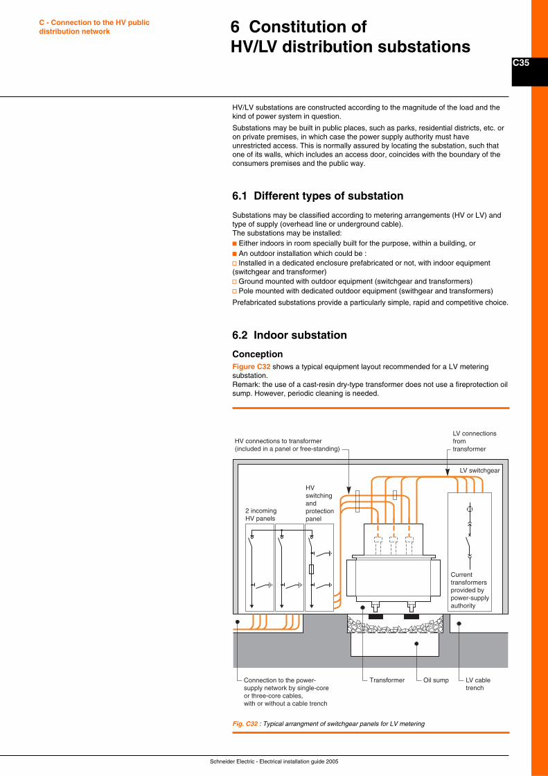
C35
Schneider Electric - Electrical installation guide 2005
C - Connection to the HV publicdistribution network
HV/LV substations are constructed according to the magnitude of the load and thekind of power system in question.
Substations may be built in public places, such as parks, residential districts, etc. oron private premises, in which case the power supply authority must haveunrestricted access. This is normally assured by locating the substation, such thatone of its walls, which includes an access door, coincides with the boundary of theconsumers premises and the public way.
6.1 Different types of substation
Substations may be classified according to metering arrangements (HV or LV) andtype of supply (overhead line or underground cable).The substations may be installed:c Either indoors in room specially built for the purpose, within a building, orc An outdoor installation which could be :v Installed in a dedicated enclosure prefabricated or not, with indoor equipment(switchgear and transformer)v Ground mounted with outdoor equipment (switchgear and transformers)v Pole mounted with dedicated outdoor equipment (swithgear and transformers)
Prefabricated substations provide a particularly simple, rapid and competitive choice.
6.2 Indoor substation
ConceptionFigure C32 shows a typical equipment layout recommended for a LV meteringsubstation.Remark: the use of a cast-resin dry-type transformer does not use a fireprotection oilsump. However, periodic cleaning is needed.
6 Constitution ofHV/LV distribution substations
Fig. C32 : Typical arrangment of switchgear panels for LV metering
LV switchgear
LV connections fromtransformer
HV connections to transformer(included in a panel or free-standing)
2 incomingHV panels
HV switching and protection panel
Transformer LV cable trench
Oil sumpConnection to the power-supply network by single-core or three-core cables, with or without a cable trench
Current transformers provided by power-supply authority
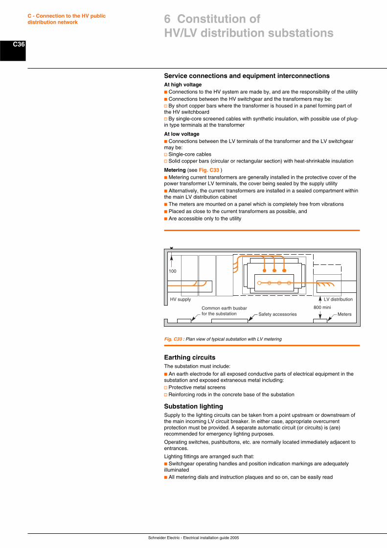
Schneider Electric - Electrical installation guide 2005
C36
C - Connection to the HV publicdistribution network
Service connections and equipment interconnectionsAt high voltagec Connections to the HV system are made by, and are the responsibility of the utilityc Connections between the HV switchgear and the transformers may be:v By short copper bars where the transformer is housed in a panel forming part ofthe HV switchboardv By single-core screened cables with synthetic insulation, with possible use of plug-in type terminals at the transformer
At low voltagec Connections between the LV terminals of the transformer and the LV switchgearmay be:v Single-core cablesv Solid copper bars (circular or rectangular section) with heat-shrinkable insulation
Metering (see Fig. C33 )c Metering current transformers are generally installed in the protective cover of thepower transformer LV terminals, the cover being sealed by the supply utilityc Alternatively, the current transformers are installed in a sealed compartment withinthe main LV distribution cabinetc The meters are mounted on a panel which is completely free from vibrationsc Placed as close to the current transformers as possible, andc Are accessible only to the utility
Fig. C33 : Plan view of typical substation with LV metering
800 mini
HV supply LV distribution
Meters
100
Safety accessoriesCommon earth busbar for the substation
Earthing circuitsThe substation must include:
c An earth electrode for all exposed conductive parts of electrical equipment in thesubstation and exposed extraneous metal including:v Protective metal screensv Reinforcing rods in the concrete base of the substation
Substation lightingSupply to the lighting circuits can be taken from a point upstream or downstream ofthe main incoming LV circuit breaker. In either case, appropriate overcurrentprotection must be provided. A separate automatic circuit (or circuits) is (are)recommended for emergency lighting purposes.
Operating switches, pushbuttons, etc. are normally located immediately adjacent toentrances.
Lighting fittings are arranged such that:c Switchgear operating handles and position indication markings are adequatelyilluminatedc All metering dials and instruction plaques and so on, can be easily read
6 Constitution ofHV/LV distribution substations
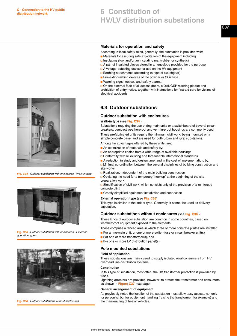
C37
Schneider Electric - Electrical installation guide 2005
C - Connection to the HV publicdistribution network
Materials for operation and safetyAccording to local safety rules, generally, the substation is provided with:c Materials for assuring safe exploitation of the equipment including:v Insulating stool and/or an insulating mat (rubber or synthetic)v A pair of insulated gloves stored in an envelope provided for the purposev A voltage-detecting device for use on the HV equipmentv Earthing attachments (according to type of switchgear)c Fire-extinguishing devices of the powder or CO2 typec Warning signs, notices and safety alarms:v On the external face of all access doors, a DANGER warning plaque andprohibition of entry notice, together with instructions for first-aid care for victims ofelectrical accidents.
6.3 Outdoor substations
Outdoor substation with enclosuresWalk-in type (see Fig. C34 )Substations requiring the use of ring-main units or a switchboard of several circuitbreakers, compact weatherproof and vermin-proof housings are commonly used.
These prefabricated units require the minimum civil work, being mounted on asimple concrete base, and are used for both urban and rural substations.
Among the advantages offered by these units, are:c An optimization of materials and safety by:v An appropriate choice from a wide range of available housingsv Conformity with all existing and foreseeable international standardsc A reduction in study and design time, and in the cost of implementation, by:v Minimal co-ordination between the several disciplines of building construction andsite worksv Realization, independent of the main building constructionv Obviating the need for a temporary “hookup” at the beginning of the sitepreparation workv Simplification of civil work, which consists only of the provision of a reinforced-concrete plinthc Greatly simplified equipment installation and connection
External operation type (see Fig. C35)This type is similar to the indoor type. Generally, it cannot be used as deliverysubstation.
Outdoor substations without enclosures (see Fig. C36 )
These kinds of outdoor substation are common in some countries, based onweatherproof equipment exposed to the elements.
These comprise a fenced area in which three or more concrete plinths are installed:c For a ring-main unit, or one or more switch-fuse or circuit breaker unit(s)c For one or more transformer(s), andc For one or more LV distribution panel(s)
Pole mounted substationsField of applicationThese substations are mainly used to supply isolated rural consumers from HVoverhead line distribution systems.
ConstitutionIn this type of substation, most often, the HV transformer protection is provided byfuses.Lightning arresters are provided, however, to protect the transformer and consumersas shown in Figure C37 next page.
General arrangement of equipmentAs previously noted the location of the substation must allow easy access, not onlyfor personnel but for equipment handling (raising the transformer, for example) andthe manœuvring of heavy vehicles.
Fig. C34 : Outdoor substation with enclosures - Walk-in type -
Fig. C35 : Outdoor substation with enclosures - Externaloperation type -
Fig. C36 : Outdoor substations without enclosures
6 Constitution ofHV/LV distribution substations
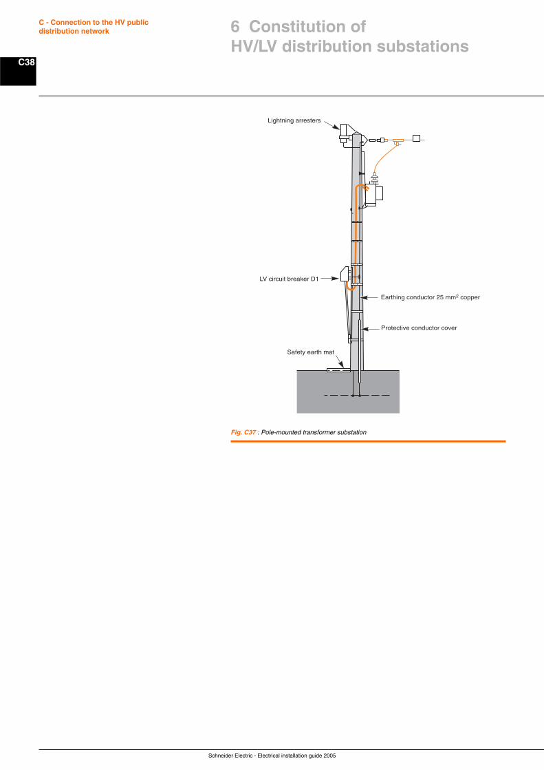
Schneider Electric - Electrical installation guide 2005
C38
C - Connection to the HV publicdistribution network 6 Constitution of
HV/LV distribution substations
Fig. C37 : Pole-mounted transformer substation
Earthing conductor 25 mm2 copper
Protective conductor cover
LV circuit breaker D1
Safety earth mat
Lightning arresters
Schneider Electric - Electrical installation guide 2005
D1
Chapter DConnection to the LV utilitydistribution network
Contents
Low voltage utility distribution networks D2
1.1 Low voltage consumers D2
1.2 Low voltage distribution networks D10
1.3 The consumer service connection D11
1.4 Quality of supply voltage D15
Tariffs and metering D16
1
2
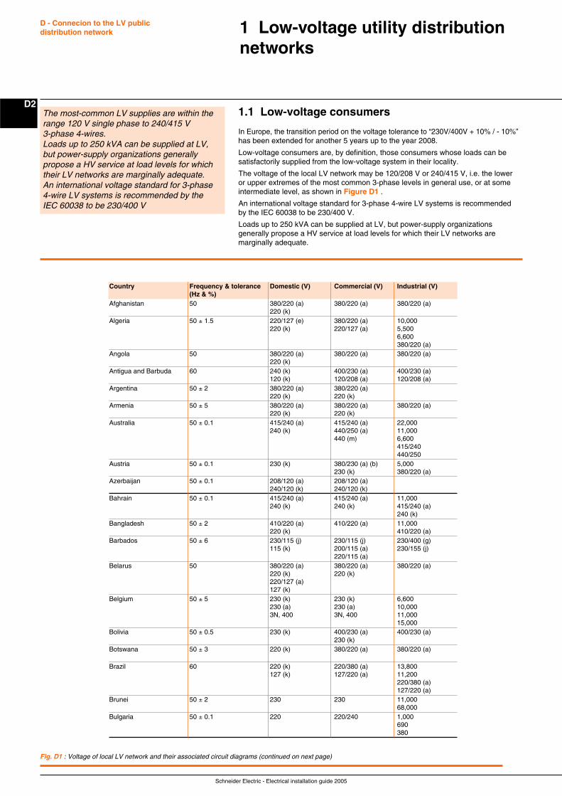
Schneider Electric - Electrical installation guide 2005
D - Connecion to the LV publicdistribution network
D21.1 Low-voltage consumers
In Europe, the transition period on the voltage tolerance to “230V/400V + 10% / - 10%”has been extended for another 5 years up to the year 2008.
Low-voltage consumers are, by definition, those consumers whose loads can besatisfactorily supplied from the low-voltage system in their locality.
The voltage of the local LV network may be 120/208 V or 240/415 V, i.e. the loweror upper extremes of the most common 3-phase levels in general use, or at someintermediate level, as shown in Figure D1 .
An international voltage standard for 3-phase 4-wire LV systems is recommendedby the IEC 60038 to be 230/400 V.
Loads up to 250 kVA can be supplied at LV, but power-supply organizationsgenerally propose a HV service at load levels for which their LV networks aremarginally adequate.
1 Low-voltage utility distributionnetworks
The most-common LV supplies are within therange 120 V single phase to 240/415 V3-phase 4-wires.Loads up to 250 kVA can be supplied at LV,but power-supply organizations generallypropose a HV service at load levels for whichtheir LV networks are marginally adequate.An international voltage standard for 3-phase4-wire LV systems is recommended by theIEC 60038 to be 230/400 V
Fig. D1 : Voltage of local LV network and their associated circuit diagrams (continued on next page)
Country Frequency & tolerance Domestic (V) Commercial (V) Industrial (V)(Hz & %)
Afghanistan 50 380/220 (a) 380/220 (a) 380/220 (a)220 (k)
Algeria 50 ± 1.5 220/127 (e) 380/220 (a) 10,000220 (k) 220/127 (a) 5,500
6,600380/220 (a)
Angola 50 380/220 (a) 380/220 (a) 380/220 (a)220 (k)
Antigua and Barbuda 60 240 (k) 400/230 (a) 400/230 (a)120 (k) 120/208 (a) 120/208 (a)
Argentina 50 ± 2 380/220 (a) 380/220 (a)220 (k) 220 (k)
Armenia 50 ± 5 380/220 (a) 380/220 (a) 380/220 (a)220 (k) 220 (k)
Australia 50 ± 0.1 415/240 (a) 415/240 (a) 22,000240 (k) 440/250 (a) 11,000
440 (m) 6,600415/240440/250
Austria 50 ± 0.1 230 (k) 380/230 (a) (b) 5,000230 (k) 380/220 (a)
Azerbaijan 50 ± 0.1 208/120 (a) 208/120 (a)240/120 (k) 240/120 (k)
Bahrain 50 ± 0.1 415/240 (a) 415/240 (a) 11,000240 (k) 240 (k) 415/240 (a)
240 (k)Bangladesh 50 ± 2 410/220 (a) 410/220 (a) 11,000
220 (k) 410/220 (a)Barbados 50 ± 6 230/115 (j) 230/115 (j) 230/400 (g)
115 (k) 200/115 (a) 230/155 (j)220/115 (a)
Belarus 50 380/220 (a) 380/220 (a) 380/220 (a)220 (k) 220 (k)220/127 (a)127 (k)
Belgium 50 ± 5 230 (k) 230 (k) 6,600230 (a) 230 (a) 10,0003N, 400 3N, 400 11,000
15,000Bolivia 50 ± 0.5 230 (k) 400/230 (a) 400/230 (a)
230 (k)Botswana 50 ± 3 220 (k) 380/220 (a) 380/220 (a)
Brazil 60 220 (k) 220/380 (a) 13,800127 (k) 127/220 (a) 11,200
220/380 (a)127/220 (a)
Brunei 50 ± 2 230 230 11,00068,000
Bulgaria 50 ± 0.1 220 220/240 1,000690380
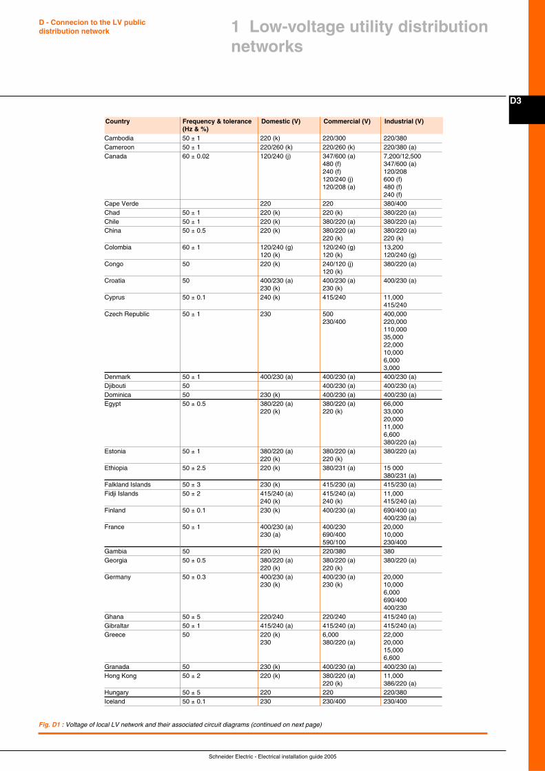
Schneider Electric - Electrical installation guide 2005
D3
D - Connecion to the LV publicdistribution network
Fig. D1 : Voltage of local LV network and their associated circuit diagrams (continued on next page)
Cambodia 50 ± 1 220 (k) 220/300 220/380Cameroon 50 ± 1 220/260 (k) 220/260 (k) 220/380 (a)Canada 60 ± 0.02 120/240 (j) 347/600 (a) 7,200/12,500
480 (f) 347/600 (a)240 (f) 120/208120/240 (j) 600 (f)120/208 (a) 480 (f)
240 (f)Cape Verde 220 220 380/400Chad 50 ± 1 220 (k) 220 (k) 380/220 (a)Chile 50 ± 1 220 (k) 380/220 (a) 380/220 (a)China 50 ± 0.5 220 (k) 380/220 (a) 380/220 (a)
220 (k) 220 (k)Colombia 60 ± 1 120/240 (g) 120/240 (g) 13,200
120 (k) 120 (k) 120/240 (g)Congo 50 220 (k) 240/120 (j) 380/220 (a)
120 (k)Croatia 50 400/230 (a) 400/230 (a) 400/230 (a)
230 (k) 230 (k)Cyprus 50 ± 0.1 240 (k) 415/240 11,000
415/240Czech Republic 50 ± 1 230 500 400,000
230/400 220,000110,00035,00022,00010,0006,0003,000
Denmark 50 ± 1 400/230 (a) 400/230 (a) 400/230 (a)Djibouti 50 400/230 (a) 400/230 (a)Dominica 50 230 (k) 400/230 (a) 400/230 (a)Egypt 50 ± 0.5 380/220 (a) 380/220 (a) 66,000
220 (k) 220 (k) 33,00020,00011,0006,600380/220 (a)
Estonia 50 ± 1 380/220 (a) 380/220 (a) 380/220 (a)220 (k) 220 (k)
Ethiopia 50 ± 2.5 220 (k) 380/231 (a) 15 000380/231 (a)
Falkland Islands 50 ± 3 230 (k) 415/230 (a) 415/230 (a)Fidji Islands 50 ± 2 415/240 (a) 415/240 (a) 11,000
240 (k) 240 (k) 415/240 (a)Finland 50 ± 0.1 230 (k) 400/230 (a) 690/400 (a)
400/230 (a)France 50 ± 1 400/230 (a) 400/230 20,000
230 (a) 690/400 10,000590/100 230/400
Gambia 50 220 (k) 220/380 380Georgia 50 ± 0.5 380/220 (a) 380/220 (a) 380/220 (a)
220 (k) 220 (k)Germany 50 ± 0.3 400/230 (a) 400/230 (a) 20,000
230 (k) 230 (k) 10,0006,000690/400400/230
Ghana 50 ± 5 220/240 220/240 415/240 (a)Gibraltar 50 ± 1 415/240 (a) 415/240 (a) 415/240 (a)Greece 50 220 (k) 6,000 22,000
230 380/220 (a) 20,00015,0006,600
Granada 50 230 (k) 400/230 (a) 400/230 (a)Hong Kong 50 ± 2 220 (k) 380/220 (a) 11,000
220 (k) 386/220 (a)Hungary 50 ± 5 220 220 220/380Iceland 50 ± 0.1 230 230/400 230/400
Country Frequency & tolerance Domestic (V) Commercial (V) Industrial (V)(Hz & %)
1 Low-voltage utility distributionnetworks
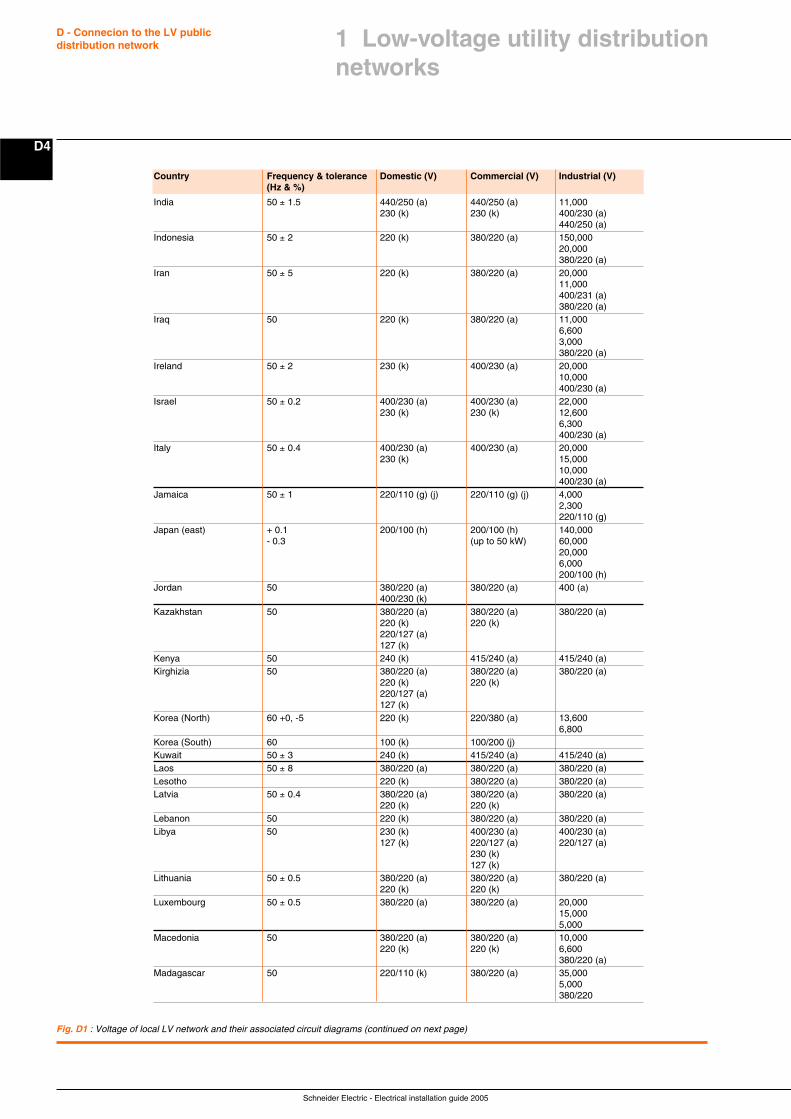
Schneider Electric - Electrical installation guide 2005
D - Connecion to the LV publicdistribution network
D4
Fig. D1 : Voltage of local LV network and their associated circuit diagrams (continued on next page)
India 50 ± 1.5 440/250 (a) 440/250 (a) 11,000230 (k) 230 (k) 400/230 (a)
440/250 (a)Indonesia 50 ± 2 220 (k) 380/220 (a) 150,000
20,000380/220 (a)
Iran 50 ± 5 220 (k) 380/220 (a) 20,00011,000400/231 (a)380/220 (a)
Iraq 50 220 (k) 380/220 (a) 11,0006,6003,000380/220 (a)
Ireland 50 ± 2 230 (k) 400/230 (a) 20,00010,000400/230 (a)
Israel 50 ± 0.2 400/230 (a) 400/230 (a) 22,000230 (k) 230 (k) 12,600
6,300400/230 (a)
Italy 50 ± 0.4 400/230 (a) 400/230 (a) 20,000230 (k) 15,000
10,000400/230 (a)
Jamaica 50 ± 1 220/110 (g) (j) 220/110 (g) (j) 4,0002,300220/110 (g)
Japan (east) + 0.1 200/100 (h) 200/100 (h) 140,000- 0.3 (up to 50 kW) 60,000
20,0006,000200/100 (h)
Jordan 50 380/220 (a) 380/220 (a) 400 (a)400/230 (k)
Kazakhstan 50 380/220 (a) 380/220 (a) 380/220 (a)220 (k) 220 (k)220/127 (a)127 (k)
Kenya 50 240 (k) 415/240 (a) 415/240 (a)Kirghizia 50 380/220 (a) 380/220 (a) 380/220 (a)
220 (k) 220 (k)220/127 (a)127 (k)
Korea (North) 60 +0, -5 220 (k) 220/380 (a) 13,6006,800
Korea (South) 60 100 (k) 100/200 (j)Kuwait 50 ± 3 240 (k) 415/240 (a) 415/240 (a)Laos 50 ± 8 380/220 (a) 380/220 (a) 380/220 (a)Lesotho 220 (k) 380/220 (a) 380/220 (a)Latvia 50 ± 0.4 380/220 (a) 380/220 (a) 380/220 (a)
220 (k) 220 (k)Lebanon 50 220 (k) 380/220 (a) 380/220 (a)Libya 50 230 (k) 400/230 (a) 400/230 (a)
127 (k) 220/127 (a) 220/127 (a)230 (k)127 (k)
Lithuania 50 ± 0.5 380/220 (a) 380/220 (a) 380/220 (a)220 (k) 220 (k)
Luxembourg 50 ± 0.5 380/220 (a) 380/220 (a) 20,00015,0005,000
Macedonia 50 380/220 (a) 380/220 (a) 10,000220 (k) 220 (k) 6,600
380/220 (a)Madagascar 50 220/110 (k) 380/220 (a) 35,000
5,000380/220
Country Frequency & tolerance Domestic (V) Commercial (V) Industrial (V)(Hz & %)
1 Low-voltage utility distributionnetworks
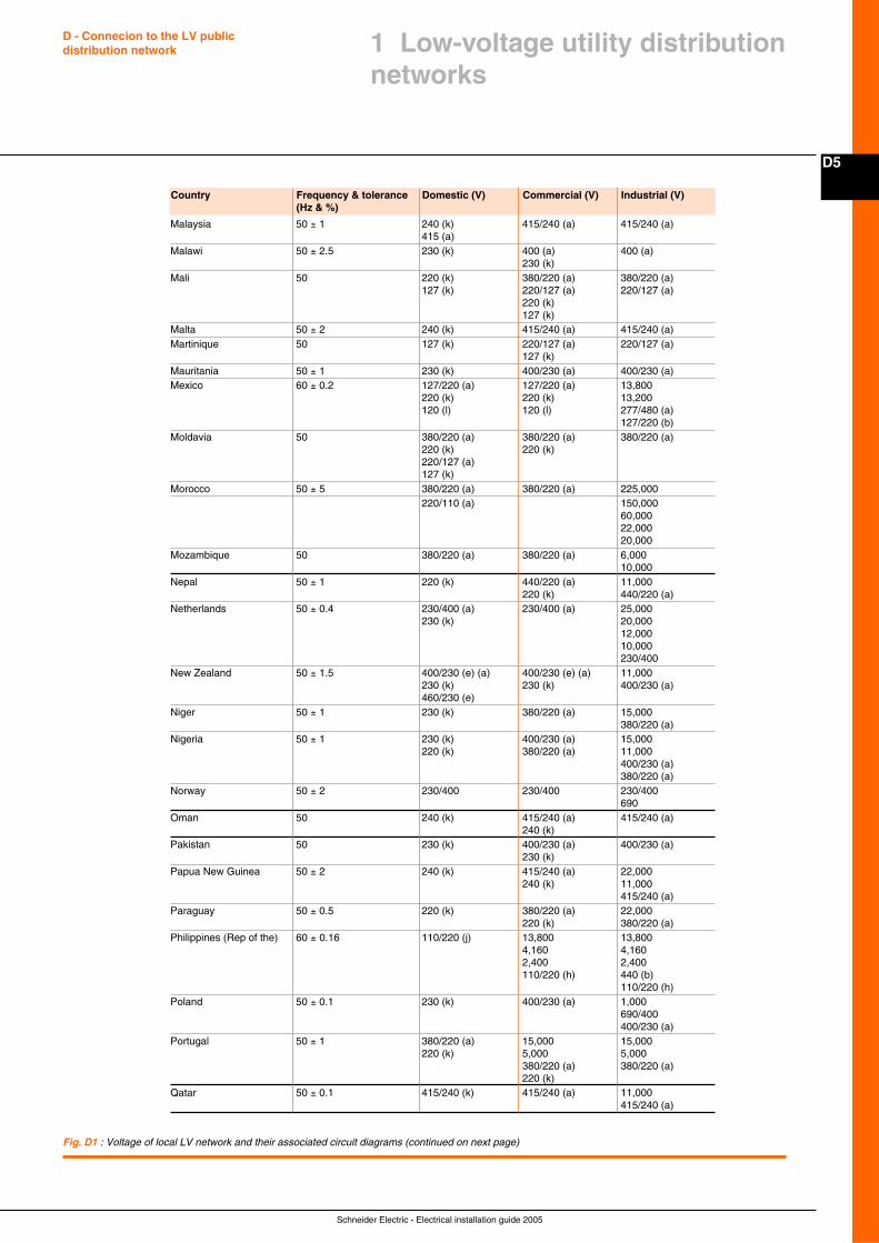
Schneider Electric - Electrical installation guide 2005
D5
D - Connecion to the LV publicdistribution network
Fig. D1 : Voltage of local LV network and their associated circuit diagrams (continued on next page)
1 Low-voltage utility distributionnetworks
Country Frequency & tolerance Domestic (V) Commercial (V) Industrial (V)(Hz & %)
Malaysia 50 ± 1 240 (k) 415/240 (a) 415/240 (a)415 (a)
Malawi 50 ± 2.5 230 (k) 400 (a) 400 (a)230 (k)
Mali 50 220 (k) 380/220 (a) 380/220 (a)127 (k) 220/127 (a) 220/127 (a)
220 (k)127 (k)
Malta 50 ± 2 240 (k) 415/240 (a) 415/240 (a)Martinique 50 127 (k) 220/127 (a) 220/127 (a)
127 (k)Mauritania 50 ± 1 230 (k) 400/230 (a) 400/230 (a)Mexico 60 ± 0.2 127/220 (a) 127/220 (a) 13,800
220 (k) 220 (k) 13,200120 (l) 120 (l) 277/480 (a)
127/220 (b)Moldavia 50 380/220 (a) 380/220 (a) 380/220 (a)
220 (k) 220 (k)220/127 (a)127 (k)
Morocco 50 ± 5 380/220 (a) 380/220 (a) 225,000220/110 (a) 150,000
60,00022,00020,000
Mozambique 50 380/220 (a) 380/220 (a) 6,00010,000
Nepal 50 ± 1 220 (k) 440/220 (a) 11,000220 (k) 440/220 (a)
Netherlands 50 ± 0.4 230/400 (a) 230/400 (a) 25,000230 (k) 20,000
12,00010,000230/400
New Zealand 50 ± 1.5 400/230 (e) (a) 400/230 (e) (a) 11,000230 (k) 230 (k) 400/230 (a)460/230 (e)
Niger 50 ± 1 230 (k) 380/220 (a) 15,000380/220 (a)
Nigeria 50 ± 1 230 (k) 400/230 (a) 15,000220 (k) 380/220 (a) 11,000
400/230 (a)380/220 (a)
Norway 50 ± 2 230/400 230/400 230/400690
Oman 50 240 (k) 415/240 (a) 415/240 (a)240 (k)
Pakistan 50 230 (k) 400/230 (a) 400/230 (a)230 (k)
Papua New Guinea 50 ± 2 240 (k) 415/240 (a) 22,000240 (k) 11,000
415/240 (a)Paraguay 50 ± 0.5 220 (k) 380/220 (a) 22,000
220 (k) 380/220 (a)Philippines (Rep of the) 60 ± 0.16 110/220 (j) 13,800 13,800
4,160 4,1602,400 2,400110/220 (h) 440 (b)
110/220 (h)Poland 50 ± 0.1 230 (k) 400/230 (a) 1,000
690/400400/230 (a)
Portugal 50 ± 1 380/220 (a) 15,000 15,000220 (k) 5,000 5,000
380/220 (a) 380/220 (a)220 (k)
Qatar 50 ± 0.1 415/240 (k) 415/240 (a) 11,000415/240 (a)
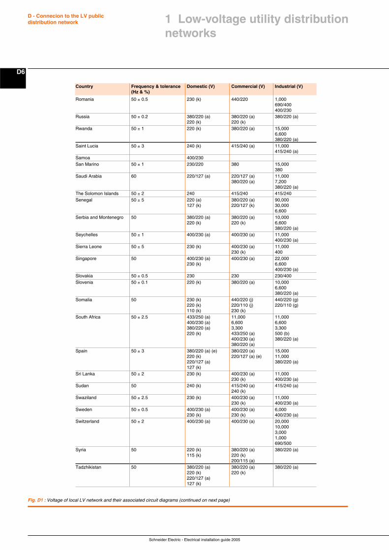
Schneider Electric - Electrical installation guide 2005
D - Connecion to the LV publicdistribution network
D6
Fig. D1 : Voltage of local LV network and their associated circuit diagrams (continued on next page)
Country Frequency & tolerance Domestic (V) Commercial (V) Industrial (V)(Hz & %)
Romania 50 ± 0.5 230 (k) 440/220 1,000690/400400/230
Russia 50 ± 0.2 380/220 (a) 380/220 (a) 380/220 (a)220 (k) 220 (k)
Rwanda 50 ± 1 220 (k) 380/220 (a) 15,0006,600380/220 (a)
Saint Lucia 50 ± 3 240 (k) 415/240 (a) 11,000415/240 (a)
Samoa 400/230San Marino 50 ± 1 230/220 380 15,000
380Saudi Arabia 60 220/127 (a) 220/127 (a) 11,000
380/220 (a) 7,200380/220 (a)
The Solomon Islands 50 ± 2 240 415/240 415/240Senegal 50 ± 5 220 (a) 380/220 (a) 90,000
127 (k) 220/127 (k) 30,0006,600
Serbia and Montenegro 50 380/220 (a) 380/220 (a) 10,000220 (k) 220 (k) 6,600
380/220 (a)Seychelles 50 ± 1 400/230 (a) 400/230 (a) 11,000
400/230 (a)Sierra Leone 50 ± 5 230 (k) 400/230 (a) 11,000
230 (k) 400Singapore 50 400/230 (a) 400/230 (a) 22,000
230 (k) 6,600400/230 (a)
Slovakia 50 ± 0.5 230 230 230/400Slovenia 50 ± 0.1 220 (k) 380/220 (a) 10,000
6,600380/220 (a)
Somalia 50 230 (k) 440/220 (j) 440/220 (g)220 (k) 220/110 (j) 220/110 (g)110 (k) 230 (k)
South Africa 50 ± 2.5 433/250 (a) 11,000 11,000400/230 (a) 6,600 6,600380/220 (a) 3,300 3,300220 (k) 433/250 (a) 500 (b)
400/230 (a) 380/220 (a)380/220 (a)
Spain 50 ± 3 380/220 (a) (e) 380/220 (a) 15,000220 (k) 220/127 (a) (e) 11,000220/127 (a) 380/220 (a)127 (k)
Sri Lanka 50 ± 2 230 (k) 400/230 (a) 11,000230 (k) 400/230 (a)
Sudan 50 240 (k) 415/240 (a) 415/240 (a)240 (k)
Swaziland 50 ± 2.5 230 (k) 400/230 (a) 11,000230 (k) 400/230 (a)
Sweden 50 ± 0.5 400/230 (a) 400/230 (a) 6,000230 (k) 230 (k) 400/230 (a)
Switzerland 50 ± 2 400/230 (a) 400/230 (a) 20,00010,0003,0001,000690/500
Syria 50 220 (k) 380/220 (a) 380/220 (a)115 (k) 220 (k)
200/115 (a)Tadzhikistan 50 380/220 (a) 380/220 (a) 380/220 (a)
220 (k) 220 (k)220/127 (a)127 (k)
1 Low-voltage utility distributionnetworks
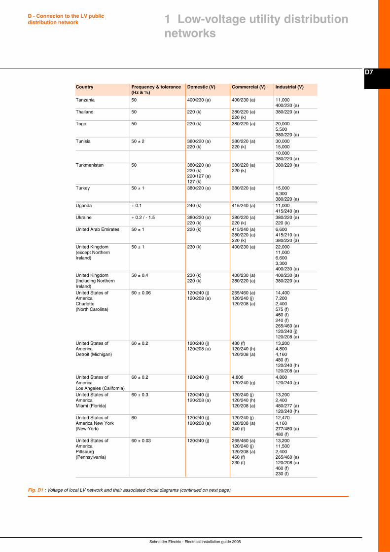
Schneider Electric - Electrical installation guide 2005
D7
D - Connecion to the LV publicdistribution network
Fig. D1 : Voltage of local LV network and their associated circuit diagrams (continued on next page)
1 Low-voltage utility distributionnetworks
Country Frequency & tolerance Domestic (V) Commercial (V) Industrial (V)(Hz & %)
Tanzania 50 400/230 (a) 400/230 (a) 11,000400/230 (a)
Thailand 50 220 (k) 380/220 (a) 380/220 (a)220 (k)
Togo 50 220 (k) 380/220 (a) 20,0005,500380/220 (a)
Tunisia 50 ± 2 380/220 (a) 380/220 (a) 30,000220 (k) 220 (k) 15,000
10,000380/220 (a)
Turkmenistan 50 380/220 (a) 380/220 (a) 380/220 (a)220 (k) 220 (k)220/127 (a)127 (k)
Turkey 50 ± 1 380/220 (a) 380/220 (a) 15,0006,300380/220 (a)
Uganda + 0.1 240 (k) 415/240 (a) 11,000415/240 (a)
Ukraine + 0.2 / - 1.5 380/220 (a) 380/220 (a) 380/220 (a)220 (k) 220 (k) 220 (k)
United Arab Emirates 50 ± 1 220 (k) 415/240 (a) 6,600380/220 (a) 415/210 (a)220 (k) 380/220 (a)
United Kingdom 50 ± 1 230 (k) 400/230 (a) 22,000(except Northern 11,000Ireland) 6,600
3,300400/230 (a)
United Kingdom 50 ± 0.4 230 (k) 400/230 (a) 400/230 (a)(Including Northern 220 (k) 380/220 (a) 380/220 (a)Ireland)United States of 60 ± 0.06 120/240 (j) 265/460 (a) 14,400America 120/208 (a) 120/240 (j) 7,200Charlotte 120/208 (a) 2,400(North Carolina) 575 (f)
460 (f)240 (f)265/460 (a)120/240 (j)120/208 (a)
United States of 60 ± 0.2 120/240 (j) 480 (f) 13,200America 120/208 (a) 120/240 (h) 4,800Detroit (Michigan) 120/208 (a) 4,160
480 (f)120/240 (h)120/208 (a)
United States of 60 ± 0.2 120/240 (j) 4,800 4,800America 120/240 (g) 120/240 (g)Los Angeles (California)United States of 60 ± 0.3 120/240 (j) 120/240 (j) 13,200America 120/208 (a) 120/240 (h) 2,400Miami (Florida) 120/208 (a) 480/277 (a)
120/240 (h)United States of 60 120/240 (j) 120/240 (j) 12,470America New York 120/208 (a) 120/208 (a) 4,160(New York) 240 (f) 277/480 (a)
480 (f)United States of 60 ± 0.03 120/240 (j) 265/460 (a) 13,200America 120/240 (j) 11,500Pittsburg 120/208 (a) 2,400(Pennsylvania) 460 (f) 265/460 (a)
230 (f) 120/208 (a)460 (f)230 (f)
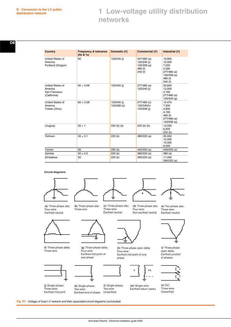
Schneider Electric - Electrical installation guide 2005
D - Connecion to the LV publicdistribution network
D8
Country Frequency & tolerance Domestic (V) Commercial (V) Industrial (V)(Hz & %)
United States of 60 120/240 (j) 227/480 (a) 19,900America 120/240 (j) 12,000Portland (Oregon) 120/208 (a) 7,200
480 (f) 2,400240 (f) 277/480 (a)
120/208 (a)480 (f)240 (f)
United States of 60 ± 0.08 120/240 (j) 277/480 (a) 20,800America 120/240 (j) 12,000San Francisco 4,160(California) 277/480 (a)
120/240 (g)United States of 60 ± 0.08 120/240 (j) 277/480 (c) 12,470America 120/208 (a) 120/240(h) 7,200Toledo (Ohio) 120/208 (j) 4,800
4,160480 (f)277/480 (a)120/208 (a)
Uruguay 50 ± 1 220 (b) (k) 220 (b) (k) 15,0006,000220 (b)
Vietnam 50 ± 0.1 220 (k) 380/220 (a) 35,00015,00010,0006,000
Yemen 50 250 (k) 440/250 (a) 440/250 (a)Zambia 50 ± 2.5 220 (k) 380/220 (a) 380 (a)Zimbabwe 50 225 (k) 390/225 (a) 11,000
390/225 (a)
Fig. D1 : Voltage of local LV network and their associated circuit diagrams (concluded)
(f) Three-phase delta: Three-wire
(g) Three-phase delta; Four-wire: Earthed mid point of one phase
(h) Three-phase open delta; Four-wire: Earthed mid point of one phase
(i) Three-phase open delta: Earthed junction of phases
(j) Single-phase; Three-wire: Earthed mid point
(k) Single-phase; Two-wire: Earthed end of phase
(l) Single-phase; Two-wire Unearthed
(m) Single-wire: Earthed return (swer)
V kV
(b) Three-phase star: Three-wire
Circuit diagrams
(a) Three-phase star; Four-wire: Earthed neutral
(c) Three-phase star; Three-wire: Earthed neutral
(d) Three-phase star; Four-wire: Non-earthed neutral
(e) Two-phase star; Three-wire Earthed neutral
(n) DC: Three-wire: Unearthed
1 Low-voltage utility distributionnetworks
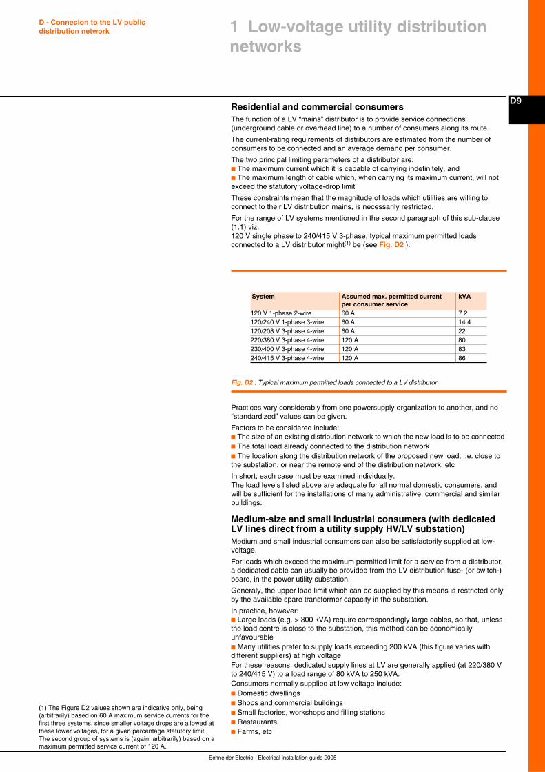
Schneider Electric - Electrical installation guide 2005
D9
D - Connecion to the LV publicdistribution network
Residential and commercial consumersThe function of a LV “mains” distributor is to provide service connections(underground cable or overhead line) to a number of consumers along its route.
The current-rating requirements of distributors are estimated from the number ofconsumers to be connected and an average demand per consumer.
The two principal limiting parameters of a distributor are:c The maximum current which it is capable of carrying indefinitely, andc The maximum length of cable which, when carrying its maximum current, will notexceed the statutory voltage-drop limit
These constraints mean that the magnitude of loads which utilities are willing toconnect to their LV distribution mains, is necessarily restricted.
For the range of LV systems mentioned in the second paragraph of this sub-clause(1.1) viz:120 V single phase to 240/415 V 3-phase, typical maximum permitted loadsconnected to a LV distributor might(1) be (see Fig. D2 ).
(1) The Figure D2 values shown are indicative only, being(arbitrarily) based on 60 A maximum service currents for thefirst three systems, since smaller voltage drops are allowed atthese lower voltages, for a given percentage statutory limit.The second group of systems is (again, arbitrarily) based on amaximum permitted service current of 120 A.
Fig. D2 : Typical maximum permitted loads connected to a LV distributor
Practices vary considerably from one powersupply organization to another, and no“standardized” values can be given.
Factors to be considered include:c The size of an existing distribution network to which the new load is to be connectedc The total load already connected to the distribution networkc The location along the distribution network of the proposed new load, i.e. close tothe substation, or near the remote end of the distribution network, etc
In short, each case must be examined individually.The load levels listed above are adequate for all normal domestic consumers, andwill be sufficient for the installations of many administrative, commercial and similarbuildings.
Medium-size and small industrial consumers (with dedicatedLV lines direct from a utility supply HV/LV substation)Medium and small industrial consumers can also be satisfactorily supplied at low-voltage.
For loads which exceed the maximum permitted limit for a service from a distributor,a dedicated cable can usually be provided from the LV distribution fuse- (or switch-)board, in the power utility substation.
Generaly, the upper load limit which can be supplied by this means is restricted onlyby the available spare transformer capacity in the substation.
In practice, however:c Large loads (e.g. > 300 kVA) require correspondingly large cables, so that, unlessthe load centre is close to the substation, this method can be economicallyunfavourablec Many utilities prefer to supply loads exceeding 200 kVA (this figure varies withdifferent suppliers) at high voltageFor these reasons, dedicated supply lines at LV are generally applied (at 220/380 Vto 240/415 V) to a load range of 80 kVA to 250 kVA.Consumers normally supplied at low voltage include:c Domestic dwellingsc Shops and commercial buildingsc Small factories, workshops and filling stationsc Restaurantsc Farms, etc
1 Low-voltage utility distributionnetworks
System Assumed max. permitted current kVAper consumer service
120 V 1-phase 2-wire 60 A 7.2120/240 V 1-phase 3-wire 60 A 14.4120/208 V 3-phase 4-wire 60 A 22220/380 V 3-phase 4-wire 120 A 80230/400 V 3-phase 4-wire 120 A 83240/415 V 3-phase 4-wire 120 A 86
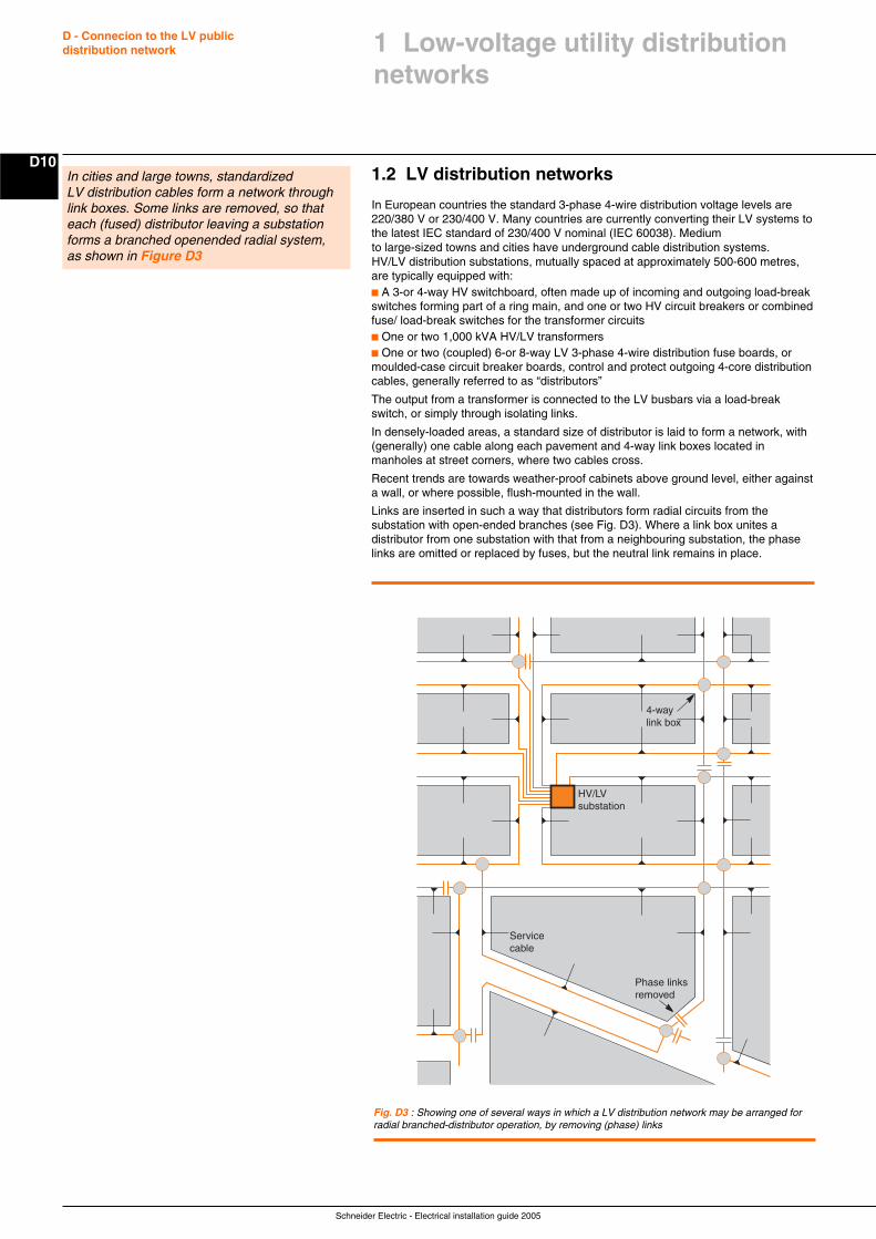
Schneider Electric - Electrical installation guide 2005
D - Connecion to the LV publicdistribution network
D101.2 LV distribution networks
In European countries the standard 3-phase 4-wire distribution voltage levels are220/380 V or 230/400 V. Many countries are currently converting their LV systems tothe latest IEC standard of 230/400 V nominal (IEC 60038). Mediumto large-sized towns and cities have underground cable distribution systems.HV/LV distribution substations, mutually spaced at approximately 500-600 metres,are typically equipped with:c A 3-or 4-way HV switchboard, often made up of incoming and outgoing load-breakswitches forming part of a ring main, and one or two HV circuit breakers or combinedfuse/ load-break switches for the transformer circuitsc One or two 1,000 kVA HV/LV transformersc One or two (coupled) 6-or 8-way LV 3-phase 4-wire distribution fuse boards, ormoulded-case circuit breaker boards, control and protect outgoing 4-core distributioncables, generally referred to as “distributors”
The output from a transformer is connected to the LV busbars via a load-breakswitch, or simply through isolating links.
In densely-loaded areas, a standard size of distributor is laid to form a network, with(generally) one cable along each pavement and 4-way link boxes located inmanholes at street corners, where two cables cross.
Recent trends are towards weather-proof cabinets above ground level, either againsta wall, or where possible, flush-mounted in the wall.
Links are inserted in such a way that distributors form radial circuits from thesubstation with open-ended branches (see Fig. D3). Where a link box unites adistributor from one substation with that from a neighbouring substation, the phaselinks are omitted or replaced by fuses, but the neutral link remains in place.
In cities and large towns, standardizedLV distribution cables form a network throughlink boxes. Some links are removed, so thateach (fused) distributor leaving a substationforms a branched openended radial system,as shown in Figure D3
Fig. D3 : Showing one of several ways in which a LV distribution network may be arranged forradial branched-distributor operation, by removing (phase) links
4-way link box
HV/LVsubstation
Servicecable
Phase links removed
1 Low-voltage utility distributionnetworks
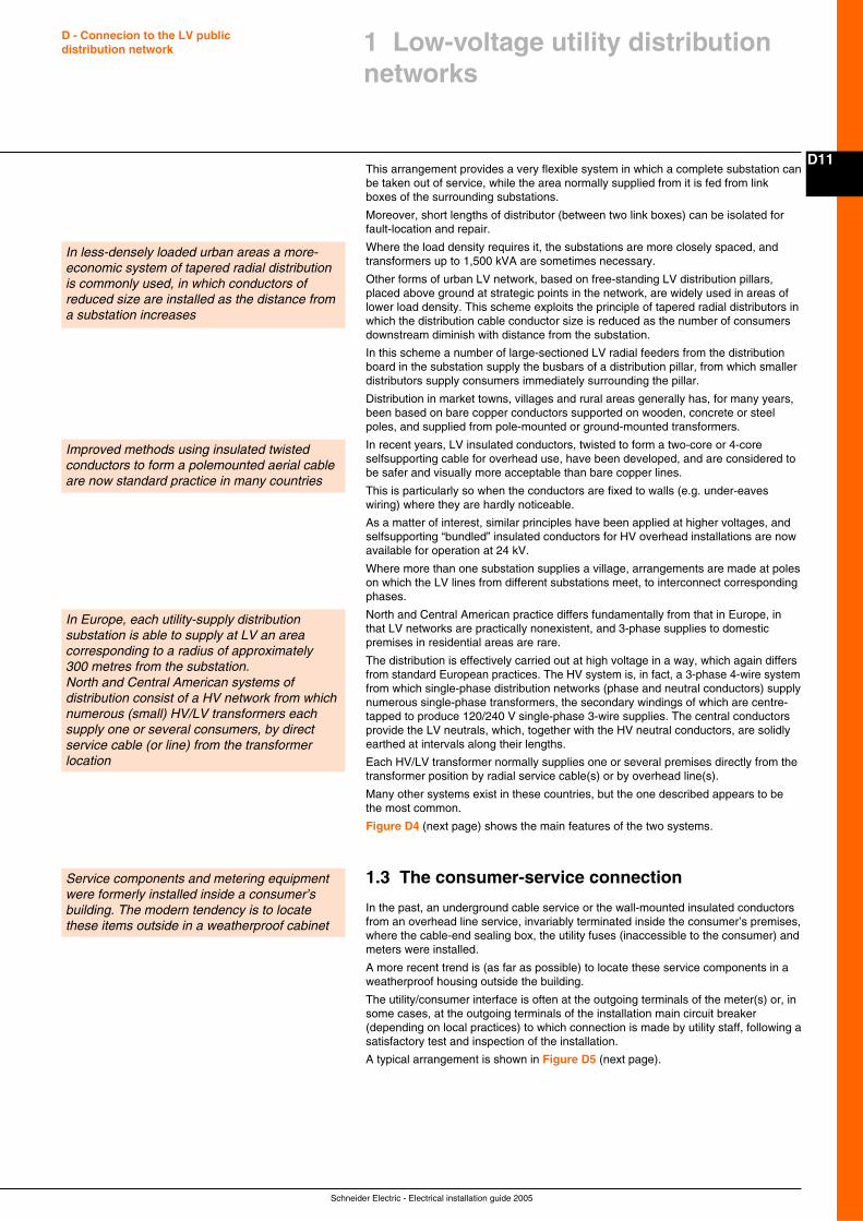
Schneider Electric - Electrical installation guide 2005
D11
D - Connecion to the LV publicdistribution network
In less-densely loaded urban areas a more-economic system of tapered radial distributionis commonly used, in which conductors ofreduced size are installed as the distance froma substation increases
Improved methods using insulated twistedconductors to form a polemounted aerial cableare now standard practice in many countries
1 Low-voltage utility distributionnetworks
This arrangement provides a very flexible system in which a complete substation canbe taken out of service, while the area normally supplied from it is fed from linkboxes of the surrounding substations.
Moreover, short lengths of distributor (between two link boxes) can be isolated forfault-location and repair.
Where the load density requires it, the substations are more closely spaced, andtransformers up to 1,500 kVA are sometimes necessary.
Other forms of urban LV network, based on free-standing LV distribution pillars,placed above ground at strategic points in the network, are widely used in areas oflower load density. This scheme exploits the principle of tapered radial distributors inwhich the distribution cable conductor size is reduced as the number of consumersdownstream diminish with distance from the substation.
In this scheme a number of large-sectioned LV radial feeders from the distributionboard in the substation supply the busbars of a distribution pillar, from which smallerdistributors supply consumers immediately surrounding the pillar.
Distribution in market towns, villages and rural areas generally has, for many years,been based on bare copper conductors supported on wooden, concrete or steelpoles, and supplied from pole-mounted or ground-mounted transformers.
In recent years, LV insulated conductors, twisted to form a two-core or 4-coreselfsupporting cable for overhead use, have been developed, and are considered tobe safer and visually more acceptable than bare copper lines.
This is particularly so when the conductors are fixed to walls (e.g. under-eaveswiring) where they are hardly noticeable.
As a matter of interest, similar principles have been applied at higher voltages, andselfsupporting “bundled” insulated conductors for HV overhead installations are nowavailable for operation at 24 kV.
Where more than one substation supplies a village, arrangements are made at poleson which the LV lines from different substations meet, to interconnect correspondingphases.
North and Central American practice differs fundamentally from that in Europe, inthat LV networks are practically nonexistent, and 3-phase supplies to domesticpremises in residential areas are rare.
The distribution is effectively carried out at high voltage in a way, which again differsfrom standard European practices. The HV system is, in fact, a 3-phase 4-wire systemfrom which single-phase distribution networks (phase and neutral conductors) supplynumerous single-phase transformers, the secondary windings of which are centre-tapped to produce 120/240 V single-phase 3-wire supplies. The central conductorsprovide the LV neutrals, which, together with the HV neutral conductors, are solidlyearthed at intervals along their lengths.
Each HV/LV transformer normally supplies one or several premises directly from thetransformer position by radial service cable(s) or by overhead line(s).
Many other systems exist in these countries, but the one described appears to bethe most common.
Figure D4 (next page) shows the main features of the two systems.
1.3 The consumer-service connection
In the past, an underground cable service or the wall-mounted insulated conductorsfrom an overhead line service, invariably terminated inside the consumer’s premises,where the cable-end sealing box, the utility fuses (inaccessible to the consumer) andmeters were installed.
A more recent trend is (as far as possible) to locate these service components in aweatherproof housing outside the building.
The utility/consumer interface is often at the outgoing terminals of the meter(s) or, insome cases, at the outgoing terminals of the installation main circuit breaker(depending on local practices) to which connection is made by utility staff, following asatisfactory test and inspection of the installation.
A typical arrangement is shown in Figure D5 (next page).
In Europe, each utility-supply distributionsubstation is able to supply at LV an areacorresponding to a radius of approximately300 metres from the substation.North and Central American systems ofdistribution consist of a HV network from whichnumerous (small) HV/LV transformers eachsupply one or several consumers, by directservice cable (or line) from the transformerlocation
Service components and metering equipmentwere formerly installed inside a consumer’sbuilding. The modern tendency is to locatethese items outside in a weatherproof cabinet
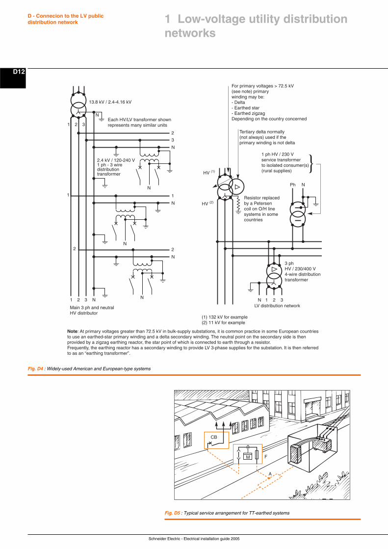
Schneider Electric - Electrical installation guide 2005
D - Connecion to the LV publicdistribution network
D12
Fig. D4 : Widely-used American and European-type systems
Fig. D5 : Typical service arrangement for TT-earthed systems
N
2
N
N
1
N
3
N
N
2
1 2 3
N
13.8 kV / 2.4-4.16 kV
N3
2
1
21 N
Ph N
HV (1)
HV (2)
1 ph HV / 230 Vservice transformerto isolated consumer(s)(rural supplies)
For primary voltages > 72.5 kV (see note) primary winding may be:- Delta- Earthed star- Earthed zigzagDepending on the country concerned
Tertiary delta normally (not always) used if the primary winding is not delta
Main 3 ph and neutral HV distributor
(1) 132 kV for example (2) 11 kV for example
Note: At primary voltages greater than 72.5 kV in bulk-supply substations, it is common practice in some European countries to use an earthed-star primary winding and a delta secondary winding. The neutral point on the secondary side is then provided by a zigzag earthing reactor, the star point of which is connected to earth through a resistor. Frequently, the earthing reactor has a secondary winding to provide LV 3-phase supplies for the substation. It is then referredto as an “earthing transformer”.
LV distribution network1 2 3
3 phHV / 230/400 V4-wire distributiontransformer
Resistor replaced by a Petersen coil on O/H line systems in somecountries
2.4 kV / 120-240 V1 ph - 3 wiredistributiontransformer
Each HV/LV transformer shownrepresents many similar units
CB
F
A
M
1 Low-voltage utility distributionnetworks
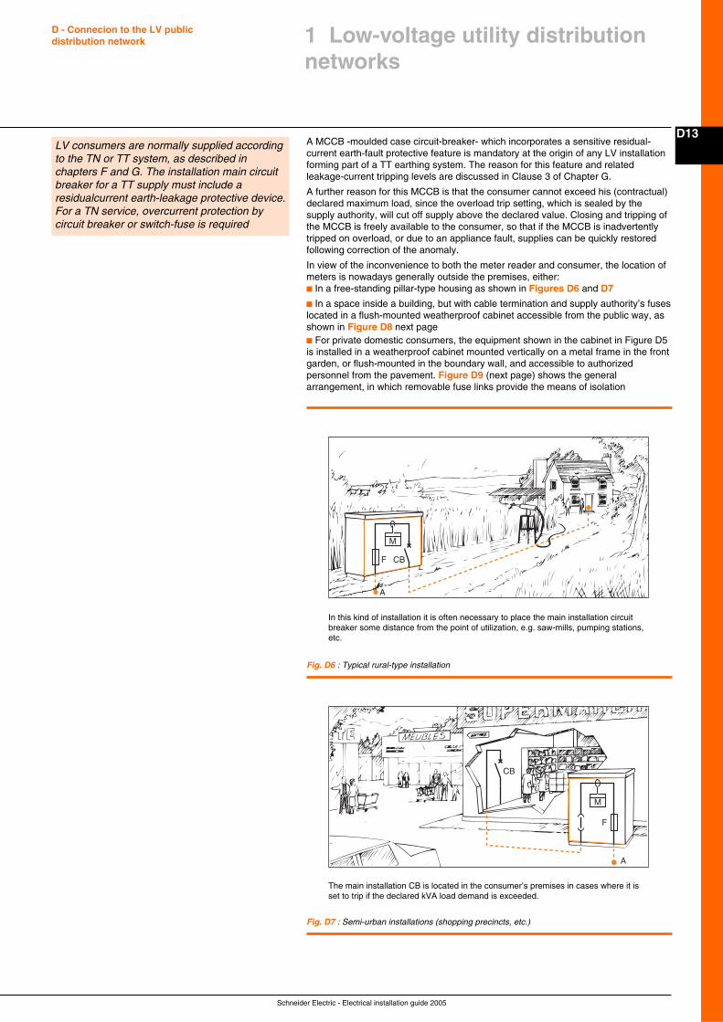
Schneider Electric - Electrical installation guide 2005
D13
D - Connecion to the LV publicdistribution network
A MCCB -moulded case circuit-breaker- which incorporates a sensitive residual-current earth-fault protective feature is mandatory at the origin of any LV installationforming part of a TT earthing system. The reason for this feature and relatedleakage-current tripping levels are discussed in Clause 3 of Chapter G.
A further reason for this MCCB is that the consumer cannot exceed his (contractual)declared maximum load, since the overload trip setting, which is sealed by thesupply authority, will cut off supply above the declared value. Closing and tripping ofthe MCCB is freely available to the consumer, so that if the MCCB is inadvertentlytripped on overload, or due to an appliance fault, supplies can be quickly restoredfollowing correction of the anomaly.
In view of the inconvenience to both the meter reader and consumer, the location ofmeters is nowadays generally outside the premises, either:c In a free-standing pillar-type housing as shown in Figures D6 and D7
c In a space inside a building, but with cable termination and supply authority’s fuseslocated in a flush-mounted weatherproof cabinet accessible from the public way, asshown in Figure D8 next pagec For private domestic consumers, the equipment shown in the cabinet in Figure D5is installed in a weatherproof cabinet mounted vertically on a metal frame in the frontgarden, or flush-mounted in the boundary wall, and accessible to authorizedpersonnel from the pavement. Figure D9 (next page) shows the generalarrangement, in which removable fuse links provide the means of isolation
1 Low-voltage utility distributionnetworks
LV consumers are normally supplied accordingto the TN or TT system, as described inchapters F and G. The installation main circuitbreaker for a TT supply must include aresidualcurrent earth-leakage protective device.For a TN service, overcurrent protection bycircuit breaker or switch-fuse is required
Fig. D6 : Typical rural-type installation
In this kind of installation it is often necessary to place the main installation circuitbreaker some distance from the point of utilization, e.g. saw-mills, pumping stations,etc.
CB
M
F
A
Fig. D7 : Semi-urban installations (shopping precincts, etc.)
The main installation CB is located in the consumer’s premises in cases where it isset to trip if the declared kVA load demand is exceeded.
CB
M
F
A
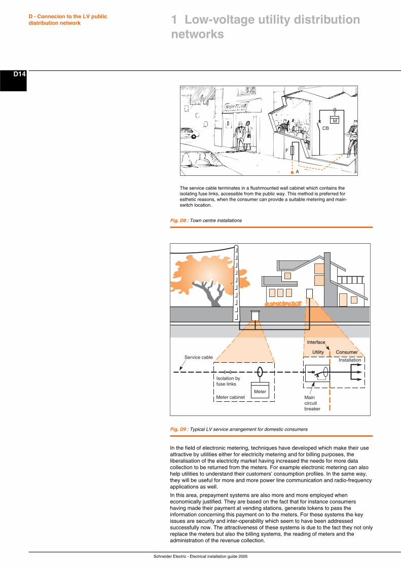
Schneider Electric - Electrical installation guide 2005
D - Connecion to the LV publicdistribution network
D14
Fig. D8 : Town centre installations
CB
M
F
A
The service cable terminates in a flushmounted wall cabinet which contains theisolating fuse links, accessible from the public way. This method is preferred foresthetic reasons, when the consumer can provide a suitable metering and main-switch location.
In the field of electronic metering, techniques have developed which make their useattractive by utilities either for electricity metering and for billing purposes, theliberalisation of the electricity market having increased the needs for more datacollection to be returned from the meters. For example electronic metering can alsohelp utilities to understand their customers’ consumption profiles. In the same way,they will be useful for more and more power line communication and radio-frequencyapplications as well.
In this area, prepayment systems are also more and more employed wheneconomically justified. They are based on the fact that for instance consumershaving made their payment at vending stations, generate tokens to pass theinformation concerning this payment on to the meters. For these systems the keyissues are security and inter-operability which seem to have been addressedsuccessfully now. The attractiveness of these systems is due to the fact they not onlyreplace the meters but also the billing systems, the reading of meters and theadministration of the revenue collection.
Fig. D9 : Typical LV service arrangement for domestic consumers
Isolation by fuse links
Interface
Meter cabinetMeter
Main circuit breaker
Installation
ConsumerUtilityService cable
1 Low-voltage utility distributionnetworks

Schneider Electric - Electrical installation guide 2005
D15
D - Connecion to the LV publicdistribution network
1.4 Quality of supply voltage
The quality of the LV network supply voltage in its widest sense implies:c Compliance with statutory limits of magnitude and frequencyc Freedom from continual fluctuation within those limitsc Uninterrupted power supply, except for scheduled maintenance shutdowns, or as aresult of system faults or other emergenciesc Preservation of a near-sinusoidal wave form
In this Sub-clause the maintenance of voltage magnitude only will be discussed, theremaining subjects are covered in subclause 1.3 of chapter E.
In most countries, power-supply authorities have a statutory obligation to maintainthe level of voltage at the service position of consumers within the limits of ± 5% (orin some cases ± 6% or more-see table D1) of the declared nominal value.
Again, IEC and most national standards recommend that LV appliances be designedand tested to perform satisfactorily within the limits of ± 10% of nominal voltage. Thisleaves a margin, under the worst conditions (of minus 5% at the service position, forexample) of 5% allowable voltage drop in the installation wiring.
The voltage drops in a typical distribution system occur as follows: the voltage at theHV terminals of a HV/LV transformer is normally maintained within a ± 2% band bythe action of automatic onload tapchangers of the transformers at bulk-supplysubstations, which feed the HV network from a higher-voltage subtransmissionsystem.
If the HV/LV transformer is in a location close to a bulk-supply substation, the ± 2%voltage band may be centred on a voltage level which is higher than the nominalHV value. For example, the voltage could be 20.5 kV ± 2% on a 20 kV system. Inthis case, the HV/LV distribution transformer should have its HV off-circuit tappingswitch selected to the + 2.5% tap position.
Conversely, at locations remote from bulksupply substations a value of 19.5 kV ± 2%is possible, in which case the off-circuit tapping switch should be selected to the - 5%position.
The different levels of voltage in a system are normal, and depend on the systempowerflow pattern. Moreover, these voltage differences are the reason for the term“nominal” when referring to the system voltage.
Practical application
With the HV/LV transformer correctly selected at its off-circuit tapping switch, anunloaded transformer output voltage will be held within a band of ± 2% of its no-loadvoltage output.
To ensure that the transformer can maintain the necessary voltage level when fullyloaded, the output voltage at no-load must be as high as possible without exceedingthe upper + 5% limit (adopted for this example). In present-day practice, the windingratios generally give an output voltage of about 104% at no-load(1), when nominalvoltage is applied at HV, or is corrected by the tapping switch, as described above.This would result in a voltage band of 102% to 106% in the present case.
A typical LV distribution transformer has a short-circuit reactance voltage of 5%. If itis assumed that its resistance voltage is one tenth of this value, then the voltage dropwithin the transformer when supplying full load at 0.8 power factor lagging, will be:
V% drop = R% cos ϕ + X% sin ϕ= 0.5 x 0.8 + 5 x 0.6
= 0.4 + 3 = 3.4%
The voltage band at the output terminals of the fully-loaded transformer will thereforebe (102 - 3.4) = 98.6% to (106 - 3.4) = 102.6%.
The maximum allowable voltage drop along a distributor is therefore 98.6 - 95 = 3.6%.
This means, in practical terms, that a medium-sized 230/400 V 3-phase 4-wiredistribution cable of 240 mm2 copper conductors would be able to supply a total loadof 292 kVA at 0.8 PF lagging, distributed evenly over 306 metres of the distributor.Alternatively, the same load at the premises of a single consumer could be suppliedat a distance of 153 metres from the transformer, for the same volt-drop, and so on...
As a matter of interest, the maximum rating of the cable, based on calculationsderived from IEC 60287 (1982) is 290 kVA, and so the 3.6% voltage margin is notunduly restrictive, i.e. the cable can be fully loaded for distances normally required inLV distribution systems.
Furthermore, 0.8 PF lagging is appropriate to industrial loads. In mixed semi-industrial areas 0.85 is a more common value, while 0.9 is generally used forcalculations concerning residential areas, so that the volt-drop noted above may beconsidered as a “worst case” example.
1 Low-voltage utility distributionnetworks
An adequate level of voltage at the consumerssupply-service terminals is essential forsatisfactory operation of equipment andappliances. Practical values of current, andresulting voltage drops in a typical LV system,show the importance of maintaining a highPower Factor as a means of reducing voltagedrop.
(1) Transformers designed for the 230/400 V IEC standard willhave a no-load output of 420 V, i.e. 105% of the nominalvoltage
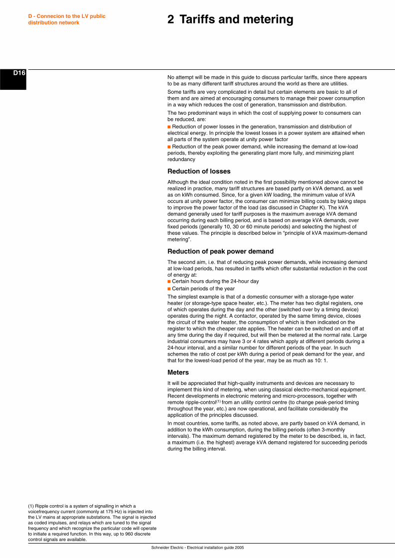
Schneider Electric - Electrical installation guide 2005
D - Connecion to the LV publicdistribution network
D16
(1) Ripple control is a system of signalling in which avoicefrequency current (commonly at 175 Hz) is injected intothe LV mains at appropriate substations. The signal is injectedas coded impulses, and relays which are tuned to the signalfrequency and which recognize the particular code will operateto initiate a required function. In this way, up to 960 discretecontrol signals are available.
2 Tariffs and metering
No attempt will be made in this guide to discuss particular tariffs, since there appearsto be as many different tariff structures around the world as there are utilities.
Some tariffs are very complicated in detail but certain elements are basic to all ofthem and are aimed at encouraging consumers to manage their power consumptionin a way which reduces the cost of generation, transmission and distribution.
The two predominant ways in which the cost of supplying power to consumers canbe reduced, are:c Reduction of power losses in the generation, transmission and distribution ofelectrical energy. In principle the lowest losses in a power system are attained whenall parts of the system operate at unity power factorc Reduction of the peak power demand, while increasing the demand at low-loadperiods, thereby exploiting the generating plant more fully, and minimizing plantredundancy
Reduction of losses
Although the ideal condition noted in the first possibility mentioned above cannot berealized in practice, many tariff structures are based partly on kVA demand, as wellas on kWh consumed. Since, for a given kW loading, the minimum value of kVAoccurs at unity power factor, the consumer can minimize billing costs by taking stepsto improve the power factor of the load (as discussed in Chapter K). The kVAdemand generally used for tariff purposes is the maximum average kVA demandoccurring during each billing period, and is based on average kVA demands, overfixed periods (generally 10, 30 or 60 minute periods) and selecting the highest ofthese values. The principle is described below in “principle of kVA maximum-demandmetering”.
Reduction of peak power demand
The second aim, i.e. that of reducing peak power demands, while increasing demandat low-load periods, has resulted in tariffs which offer substantial reduction in the costof energy at:c Certain hours during the 24-hour dayc Certain periods of the year
The simplest example is that of a domestic consumer with a storage-type waterheater (or storage-type space heater, etc.). The meter has two digital registers, oneof which operates during the day and the other (switched over by a timing device)operates during the night. A contactor, operated by the same timing device, closesthe circuit of the water heater, the consumption of which is then indicated on theregister to which the cheaper rate applies. The heater can be switched on and off atany time during the day if required, but will then be metered at the normal rate. Largeindustrial consumers may have 3 or 4 rates which apply at different periods during a24-hour interval, and a similar number for different periods of the year. In suchschemes the ratio of cost per kWh during a period of peak demand for the year, andthat for the lowest-load period of the year, may be as much as 10: 1.
Meters
It will be appreciated that high-quality instruments and devices are necessary toimplement this kind of metering, when using classical electro-mechanical equipment.Recent developments in electronic metering and micro-processors, together withremote ripple-control(1) from an utility control centre (to change peak-period timingthroughout the year, etc.) are now operational, and facilitate considerably theapplication of the principles discussed.
In most countries, some tariffs, as noted above, are partly based on kVA demand, inaddition to the kWh consumption, during the billing periods (often 3-monthlyintervals). The maximum demand registered by the meter to be described, is, in fact,a maximum (i.e. the highest) average kVA demand registered for succeeding periodsduring the billing interval.
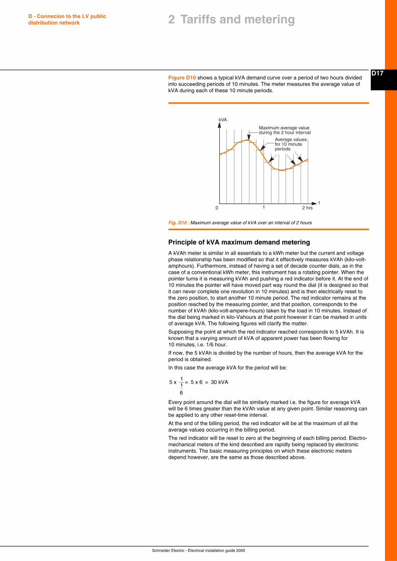
Schneider Electric - Electrical installation guide 2005
D17
D - Connecion to the LV publicdistribution network 2 Tariffs and metering
Figure D10 shows a typical kVA demand curve over a period of two hours dividedinto succeeding periods of 10 minutes. The meter measures the average value ofkVA during each of these 10 minute periods.
Fig. D10 : Maximum average value of kVA over an interval of 2 hours
0 1 2 hrst
kVA
Maximum average valueduring the 2 hour interval
Average valuesfor 10 minuteperiods
Principle of kVA maximum demand metering
A kVAh meter is similar in all essentials to a kWh meter but the current and voltagephase relationship has been modified so that it effectively measures kVAh (kilo-volt-amphours). Furthermore, instead of having a set of decade counter dials, as in thecase of a conventional kWh meter, this instrument has a rotating pointer. When thepointer turns it is measuring kVAh and pushing a red indicator before it. At the end of10 minutes the pointer will have moved part way round the dial (it is designed so thatit can never complete one revolution in 10 minutes) and is then electrically reset tothe zero position, to start another 10 minute period. The red indicator remains at theposition reached by the measuring pointer, and that position, corresponds to thenumber of kVAh (kilo-volt-ampere-hours) taken by the load in 10 minutes. Instead ofthe dial being marked in kilo-Vahours at that point however it can be marked in unitsof average kVA. The following figures will clarify the matter.
Supposing the point at which the red indicator reached corresponds to 5 kVAh. It isknown that a varying amount of kVA of apparent power has been flowing for10 minutes, i.e. 1/6 hour.
If now, the 5 kVAh is divided by the number of hours, then the average kVA for theperiod is obtained.
In this case the average kVA for the period will be:
5 x 1
= 5 x 6 = 30 kVA16
Every point around the dial will be similarly marked i.e. the figure for average kVAwill be 6 times greater than the kVAh value at any given point. Similar reasoning canbe applied to any other reset-time interval.
At the end of the billing period, the red indicator will be at the maximum of all theaverage values occurring in the billing period.
The red indicator will be reset to zero at the beginning of each billing period. Electro-mechanical meters of the kind described are rapidly being replaced by electronicinstruments. The basic measuring principles on which these electronic metersdepend however, are the same as those described above.
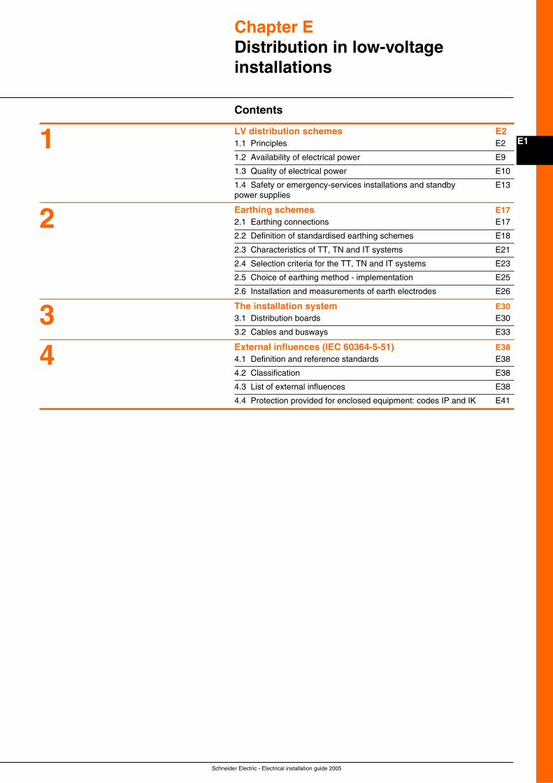
Schneider Electric - Electrical installation guide 2005
E1
Chapter EDistribution in low-voltageinstallations
Contents
LV distribution schemes E21.1 Principles E2
1.2 Availability of electrical power E9
1.3 Quality of electrical power E10
1.4 Safety or emergency-services installations and standby E13power supplies
Earthing schemes E172.1 Earthing connections E17
2.2 Definition of standardised earthing schemes E18
2.3 Characteristics of TT, TN and IT systems E21
2.4 Selection criteria for the TT, TN and IT systems E23
2.5 Choice of earthing method - implementation E25
2.6 Installation and measurements of earth electrodes E26
The installation system E303.1 Distribution boards E30
3.2 Cables and busways E33
External influences (IEC 60364-5-51) E384.1 Definition and reference standards E38
4.2 Classification E38
4.3 List of external influences E38
4.4 Protection provided for enclosed equipment: codes IP and IK E41
1
2
34
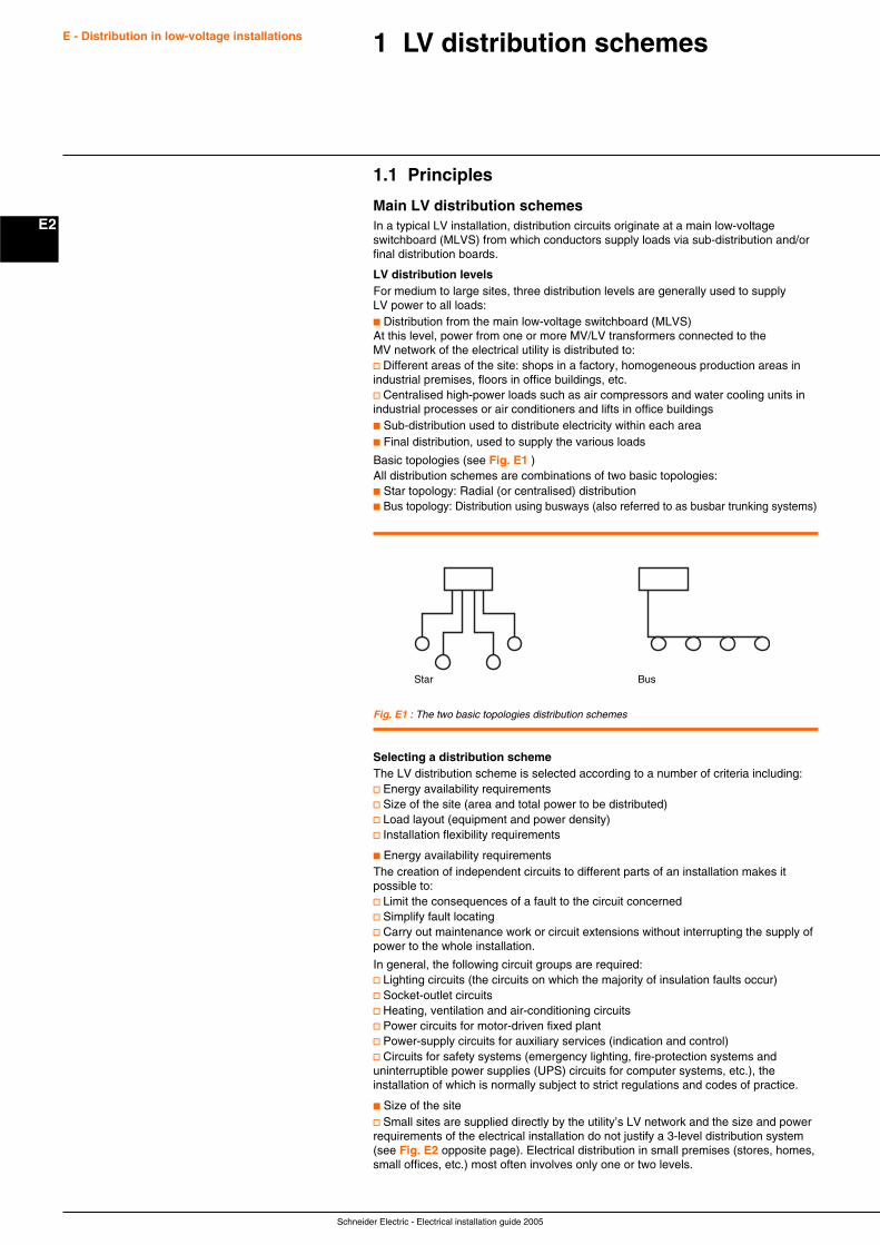
Schneider Electric - Electrical installation guide 2005
E2
E - Distribution in low-voltage installations 1 LV distribution schemes
1.1 Principles
Main LV distribution schemesIn a typical LV installation, distribution circuits originate at a main low-voltageswitchboard (MLVS) from which conductors supply loads via sub-distribution and/orfinal distribution boards.
LV distribution levelsFor medium to large sites, three distribution levels are generally used to supplyLV power to all loads:c Distribution from the main low-voltage switchboard (MLVS)At this level, power from one or more MV/LV transformers connected to theMV network of the electrical utility is distributed to:v Different areas of the site: shops in a factory, homogeneous production areas inindustrial premises, floors in office buildings, etc.v Centralised high-power loads such as air compressors and water cooling units inindustrial processes or air conditioners and lifts in office buildingsc Sub-distribution used to distribute electricity within each areac Final distribution, used to supply the various loads
Basic topologies (see Fig. E1 )All distribution schemes are combinations of two basic topologies:c Star topology: Radial (or centralised) distributionc Bus topology: Distribution using busways (also referred to as busbar trunking systems)
Fig. E1 : The two basic topologies distribution schemes
Star Bus
Selecting a distribution schemeThe LV distribution scheme is selected according to a number of criteria including:v Energy availability requirementsv Size of the site (area and total power to be distributed)v Load layout (equipment and power density)v Installation flexibility requirements
c Energy availability requirementsThe creation of independent circuits to different parts of an installation makes itpossible to:v Limit the consequences of a fault to the circuit concernedv Simplify fault locatingv Carry out maintenance work or circuit extensions without interrupting the supply ofpower to the whole installation.
In general, the following circuit groups are required:v Lighting circuits (the circuits on which the majority of insulation faults occur)v Socket-outlet circuitsv Heating, ventilation and air-conditioning circuitsv Power circuits for motor-driven fixed plantv Power-supply circuits for auxiliary services (indication and control)v Circuits for safety systems (emergency lighting, fire-protection systems anduninterruptible power supplies (UPS) circuits for computer systems, etc.), theinstallation of which is normally subject to strict regulations and codes of practice.
c Size of the sitev Small sites are supplied directly by the utility’s LV network and the size and powerrequirements of the electrical installation do not justify a 3-level distribution system(see Fig. E2 opposite page). Electrical distribution in small premises (stores, homes,small offices, etc.) most often involves only one or two levels.
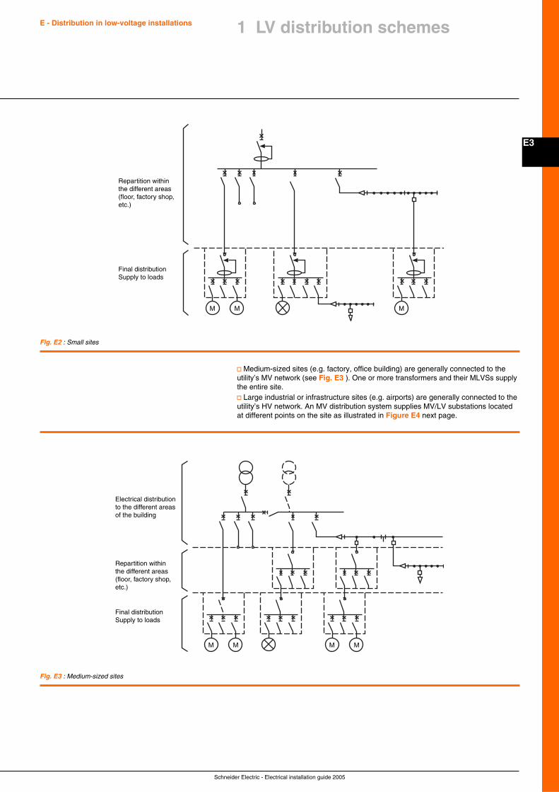
Schneider Electric - Electrical installation guide 2005
E3
E - Distribution in low-voltage installations 1 LV distribution schemes
M M M
Final distributionSupply to loads
Repartition withinthe different areas(floor, factory shop,etc.)
M M M M
Final distributionSupply to loads
Repartition withinthe different areas(floor, factory shop,etc.)
Electrical distributionto the different areasof the building
Fig. E2 : Small sites
v Medium-sized sites (e.g. factory, office building) are generally connected to theutility’s MV network (see Fig. E3 ). One or more transformers and their MLVSs supplythe entire site.v Large industrial or infrastructure sites (e.g. airports) are generally connected to theutility’s HV network. An MV distribution system supplies MV/LV substations locatedat different points on the site as illustrated in Figure E4 next page.
Fig. E3 : Medium-sized sites
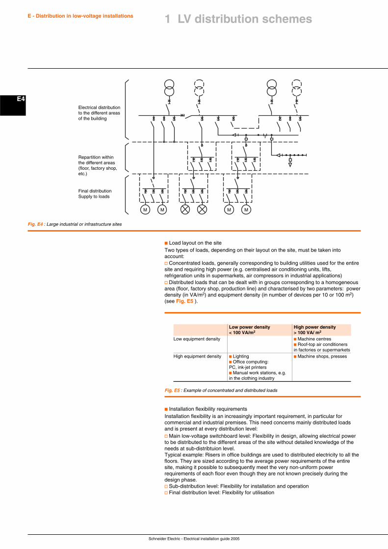
Schneider Electric - Electrical installation guide 2005
E4
E - Distribution in low-voltage installations
M M M M
Final distributionSupply to loads
Repartition withinthe different areas(floor, factory shop,etc.)
Electrical distributionto the different areasof the building
c Load layout on the siteTwo types of loads, depending on their layout on the site, must be taken intoaccount:v Concentrated loads, generally corresponding to building utilities used for the entiresite and requiring high power (e.g. centralised air conditioning units, lifts,refrigeration units in supermarkets, air compressors in industrial applications)v Distributed loads that can be dealt with in groups corresponding to a homogeneousarea (floor, factory shop, production line) and characterised by two parameters: powerdensity (in VA/m2) and equipment density (in number of devices per 10 or 100 m2)(see Fig. E5 ).
Fig. E4 : Large industrial or infrastructure sites
Low power density High power density< 100 VA/m2 > 100 VA/ m2
Low equipment density c Machine centresc Roof-top air conditionersin factories or supermarkets
High equipment density c Lighting c Machine shops, pressesc Office computing:PC, ink-jet printersc Manual work stations, e.g.in the clothing industry
Fig. E5 : Example of concentrated and distributed loads
c Installation flexibility requirementsInstallation flexibility is an increasingly important requirement, in particular forcommercial and industrial premises. This need concerns mainly distributed loadsand is present at every distribution level:v Main low-voltage switchboard level: Flexibility in design, allowing electrical powerto be distributed to the different areas of the site without detailed knowledge of theneeds at sub-distribtuion level.Typical example: Risers in office buildings are used to distributed electricity to all thefloors. They are sized according to the average power requirements of the entiresite, making it possible to subsequently meet the very non-uniform powerrequirements of each floor even though they are not known precisely during thedesign phase.v Sub-distribution level: Flexibility for installation and operationv Final distribution level: Flexibility for utilisation
1 LV distribution schemes
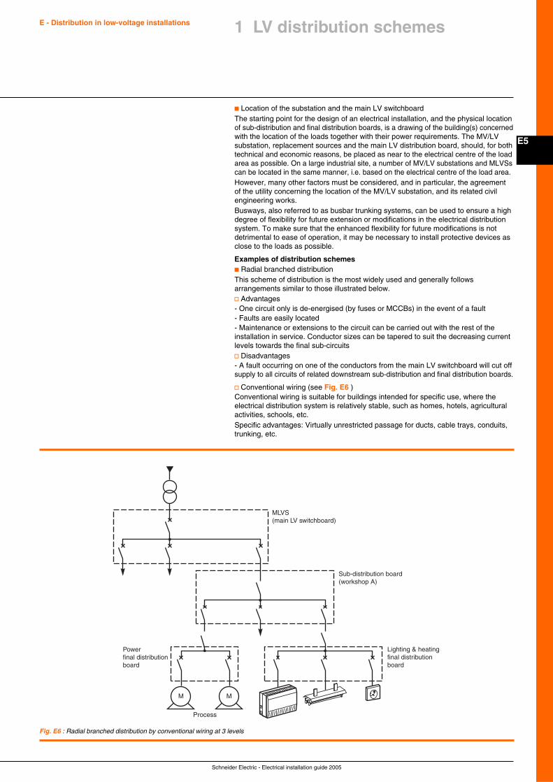
Schneider Electric - Electrical installation guide 2005
E5
E - Distribution in low-voltage installations 1 LV distribution schemes
c Location of the substation and the main LV switchboardThe starting point for the design of an electrical installation, and the physical locationof sub-distribution and final distribution boards, is a drawing of the building(s) concernedwith the location of the loads together with their power requirements. The MV/LVsubstation, replacement sources and the main LV distribution board, should, for bothtechnical and economic reasons, be placed as near to the electrical centre of the loadarea as possible. On a large industrial site, a number of MV/LV substations and MLVSscan be located in the same manner, i.e. based on the electrical centre of the load area.However, many other factors must be considered, and in particular, the agreementof the utility concerning the location of the MV/LV substation, and its related civilengineering works.Busways, also referred to as busbar trunking systems, can be used to ensure a highdegree of flexibility for future extension or modifications in the electrical distributionsystem. To make sure that the enhanced flexibility for future modifications is notdetrimental to ease of operation, it may be necessary to install protective devices asclose to the loads as possible.
Examples of distribution schemesc Radial branched distributionThis scheme of distribution is the most widely used and generally followsarrangements similar to those illustrated below.v Advantages- One circuit only is de-energised (by fuses or MCCBs) in the event of a fault- Faults are easily located- Maintenance or extensions to the circuit can be carried out with the rest of theinstallation in service. Conductor sizes can be tapered to suit the decreasing currentlevels towards the final sub-circuitsv Disadvantages- A fault occurring on one of the conductors from the main LV switchboard will cut offsupply to all circuits of related downstream sub-distribution and final distribution boards.
v Conventional wiring (see Fig. E6 )Conventional wiring is suitable for buildings intended for specific use, where theelectrical distribution system is relatively stable, such as homes, hotels, agriculturalactivities, schools, etc.Specific advantages: Virtually unrestricted passage for ducts, cable trays, conduits,trunking, etc.
Fig. E6 : Radial branched distribution by conventional wiring at 3 levels
MLVS(main LV switchboard)
Sub-distribution board(workshop A)
Process
M M
Powerfinal distributionboard
Lighting & heatingfinal distributionboard
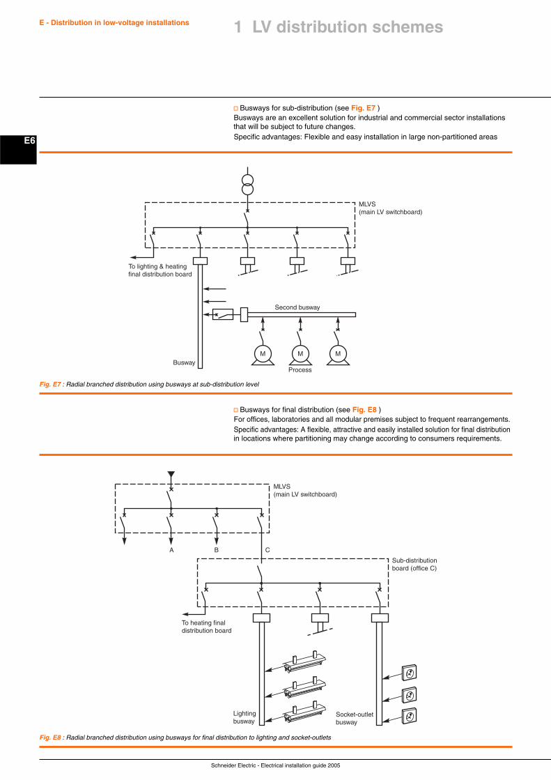
Schneider Electric - Electrical installation guide 2005
E6
E - Distribution in low-voltage installations
Fig. E7 : Radial branched distribution using busways at sub-distribution level
v Busways for sub-distribution (see Fig. E7 )Busways are an excellent solution for industrial and commercial sector installationsthat will be subject to future changes.Specific advantages: Flexible and easy installation in large non-partitioned areas
Fig. E8 : Radial branched distribution using busways for final distribution to lighting and socket-outlets
MLVS(main LV switchboard)
To lighting & heatingfinal distribution board
M M MBusway
Second busway
Process
v Busways for final distribution (see Fig. E8 )For offices, laboratories and all modular premises subject to frequent rearrangements.Specific advantages: A flexible, attractive and easily installed solution for final distributionin locations where partitioning may change according to consumers requirements.
MLVS(main LV switchboard)
Sub-distributionboard (office C)
BA C
To heating finaldistribution board
Lightingbusway
Socket-outletbusway
1 LV distribution schemes
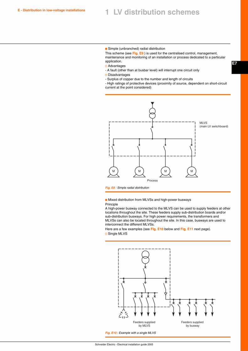
Schneider Electric - Electrical installation guide 2005
E7
E - Distribution in low-voltage installations 1 LV distribution schemes
c Simple (unbranched) radial distributionThis scheme (see Fig. E9 ) is used for the centralised control, management,maintenance and monitoring of an installation or process dedicated to a particularapplication.v Advantages- A fault (other than at busbar level) will interrupt one circuit onlyv Disadvantages- Surplus of copper due to the number and length of circuits- High ratings of protective devices (proximity of source, dependent on short-circuitcurrent at the point considered)
Fig. E9 : Simple radial distribution
MLVS(main LV switchboard)
M M M
Process
M
c Mixed distribution from MLVSs and high-power buswaysPrincipleA high-power busway connected to the MLVS can be used to supply feeders at otherlocations throughout the site. These feeders supply sub-distribution boards and/orsub-distribution busways. For high power requirements, the transformers andMLVSs can also be located throughout the site. In this case, busways are used tointerconnect the different MLVSs.Here are a few examples (see Fig. E10 below and Fig. E11 next page).v Single MLVS
Fig. E10 : Example with a single MLVS
Feeders supplied by MLVS
Feeders supplied by busway
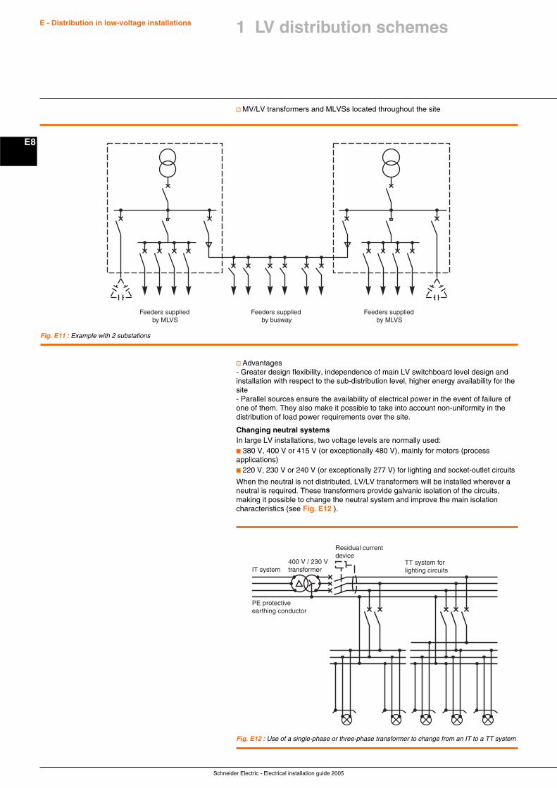
Schneider Electric - Electrical installation guide 2005
E8
E - Distribution in low-voltage installations
v Advantages- Greater design flexibility, independence of main LV switchboard level design andinstallation with respect to the sub-distribution level, higher energy availability for thesite- Parallel sources ensure the availability of electrical power in the event of failure ofone of them. They also make it possible to take into account non-uniformity in thedistribution of load power requirements over the site.
Changing neutral systemsIn large LV installations, two voltage levels are normally used:c 380 V, 400 V or 415 V (or exceptionally 480 V), mainly for motors (processapplications)c 220 V, 230 V or 240 V (or exceptionally 277 V) for lighting and socket-outlet circuits
When the neutral is not distributed, LV/LV transformers will be installed wherever aneutral is required. These transformers provide galvanic isolation of the circuits,making it possible to change the neutral system and improve the main isolationcharacteristics (see Fig. E12 ).
Fig. E11 : Example with 2 substations
Feeders supplied by MLVS
Feeders supplied by MLVS
Feeders supplied by busway
v MV/LV transformers and MLVSs located throughout the site
Fig. E12 : Use of a single-phase or three-phase transformer to change from an IT to a TT system
IT system400 V / 230 Vtransformer
TT system forlighting circuits
Residual currentdevice
PE protectiveearthing conductor
1 LV distribution schemes
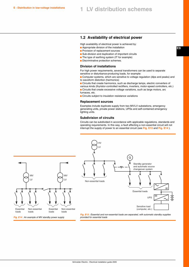
Schneider Electric - Electrical installation guide 2005
E9
E - Distribution in low-voltage installations 1 LV distribution schemes
1.2 Availability of electrical power
High availability of electrical power is achieved by:c Appropriate division of the installationc Provision of replacement sourcesc Sub-division and duplication of important circuitsc The type of earthing system (IT for example)c Discriminative protection schemes.
Division of installationsFor high power requirements, several transformers can be used to separatesensitive or disturbance-producing loads, for example:c Computer systems, which are sensitive to voltage regulation (dips and peaks) andto waveform distortion (harmonics)c Circuits that create harmonics, such as discharge lamps, electric converters ofvarious kinds (thyristor-controlled rectifiers, inverters, motor-speed controllers, etc.)c Circuits that create excessive voltage variations, such as large motors, arcfurnaces, etc.c Circuits subject to insulation resistance variations
Replacement sourcesExamples include duplicate supply from two MV/LV substations, emergencygenerating units, private power stations, UPSs and self-contained emergencylighting units.
Subdivision of circuitsCircuits can be subdivided in accordance with applicable regulations, standards andoperating requirements. In this way, a fault affecting a non-essential circuit will notinterrupt the supply of power to an essential circuit (see Fig. E13 and Fig. E14 ).
Fig. E13 : Essential and non-essential loads are separated, with automatic standby suppliesprovided for essential loadsFig. E14 : An example of MV standby power supply
G
Standby generator and automatic source changeover system
Essential loads
Non-essential loads
HV
LV
UPS
Sensitive load(computer, etc.)Essential
loads
MV
LV
Non-essentialloads
Essentialloads
Non-essentialloads
MV
LV
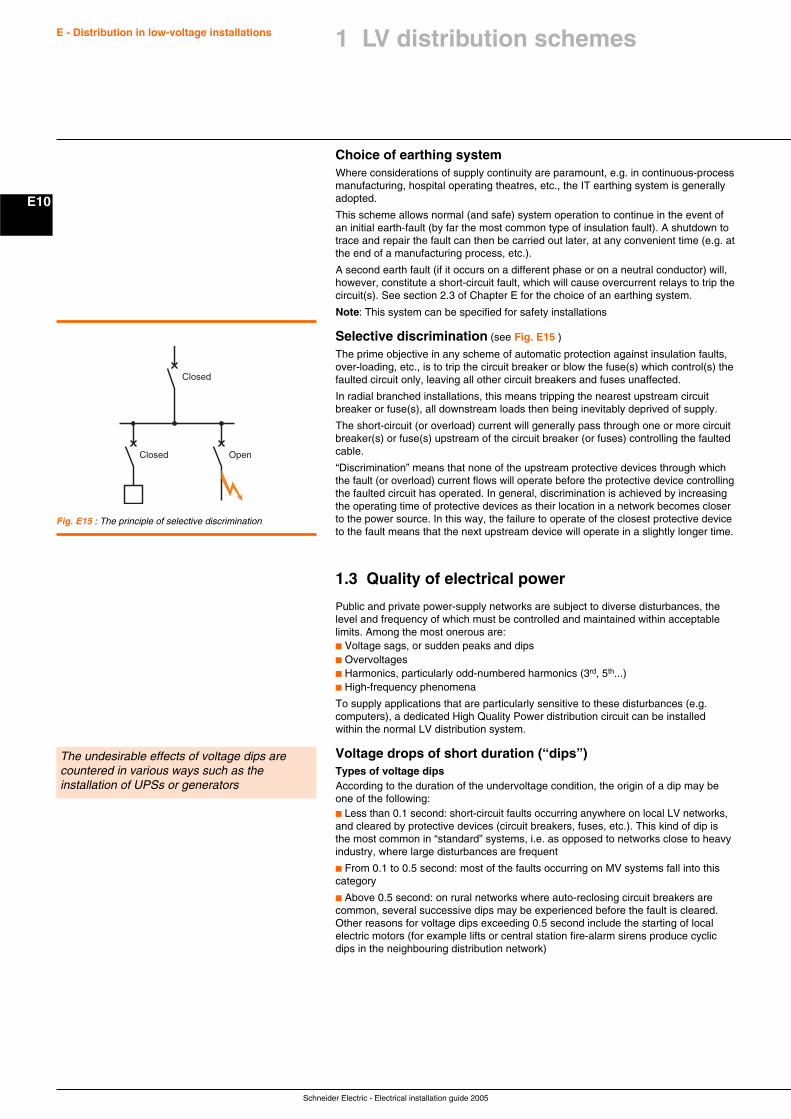
Schneider Electric - Electrical installation guide 2005
E10
E - Distribution in low-voltage installations
Choice of earthing systemWhere considerations of supply continuity are paramount, e.g. in continuous-processmanufacturing, hospital operating theatres, etc., the IT earthing system is generallyadopted.
This scheme allows normal (and safe) system operation to continue in the event ofan initial earth-fault (by far the most common type of insulation fault). A shutdown totrace and repair the fault can then be carried out later, at any convenient time (e.g. atthe end of a manufacturing process, etc.).
A second earth fault (if it occurs on a different phase or on a neutral conductor) will,however, constitute a short-circuit fault, which will cause overcurrent relays to trip thecircuit(s). See section 2.3 of Chapter E for the choice of an earthing system.
Note: This system can be specified for safety installations
Selective discrimination (see Fig. E15 )
The prime objective in any scheme of automatic protection against insulation faults,over-loading, etc., is to trip the circuit breaker or blow the fuse(s) which control(s) thefaulted circuit only, leaving all other circuit breakers and fuses unaffected.
In radial branched installations, this means tripping the nearest upstream circuitbreaker or fuse(s), all downstream loads then being inevitably deprived of supply.
The short-circuit (or overload) current will generally pass through one or more circuitbreaker(s) or fuse(s) upstream of the circuit breaker (or fuses) controlling the faultedcable.
“Discrimination” means that none of the upstream protective devices through whichthe fault (or overload) current flows will operate before the protective device controllingthe faulted circuit has operated. In general, discrimination is achieved by increasingthe operating time of protective devices as their location in a network becomes closerto the power source. In this way, the failure to operate of the closest protective deviceto the fault means that the next upstream device will operate in a slightly longer time.
1.3 Quality of electrical power
Public and private power-supply networks are subject to diverse disturbances, thelevel and frequency of which must be controlled and maintained within acceptablelimits. Among the most onerous are:c Voltage sags, or sudden peaks and dipsc Overvoltagesc Harmonics, particularly odd-numbered harmonics (3rd, 5th...)c High-frequency phenomena
To supply applications that are particularly sensitive to these disturbances (e.g.computers), a dedicated High Quality Power distribution circuit can be installedwithin the normal LV distribution system.
Voltage drops of short duration (“dips”)Types of voltage dipsAccording to the duration of the undervoltage condition, the origin of a dip may beone of the following:c Less than 0.1 second: short-circuit faults occurring anywhere on local LV networks,and cleared by protective devices (circuit breakers, fuses, etc.). This kind of dip isthe most common in “standard” systems, i.e. as opposed to networks close to heavyindustry, where large disturbances are frequent
c From 0.1 to 0.5 second: most of the faults occurring on MV systems fall into thiscategory
c Above 0.5 second: on rural networks where auto-reclosing circuit breakers arecommon, several successive dips may be experienced before the fault is cleared.Other reasons for voltage dips exceeding 0.5 second include the starting of localelectric motors (for example lifts or central station fire-alarm sirens produce cyclicdips in the neighbouring distribution network)
Fig. E15 : The principle of selective discrimination
Closed Open
Closed
The undesirable effects of voltage dips arecountered in various ways such as theinstallation of UPSs or generators
1 LV distribution schemes
Schneider Electric - Electrical installation guide 2005
E11
E - Distribution in low-voltage installations 1 LV distribution schemes
Some consequences and solutionsAmong the numerous undesirable consequences of voltage dips, the following maybe cited:c Depending on the severity of the dip and the type of loads in a given installation,there can be the risk of a heavy current surge when normal voltage is restored, withthe consequent tripping of main circuit breakers.A possible solution is a scheme with automatic load shedding and staged re-connection of apparatuses requiring high restarting currents, e.g. cold incandescentlamps and resistive heating loadsc In all computer-based applications, such as: Word processing, informationtechnology, machine-tool control, processes and so on, voltage dips are unacceptable,since the loss of information or destruction of a programme can occur, withcatastrophic consequences. Some degree of voltage variation can be tolerated andvoltage-stabilising circuits are built-in for this purpose, but the universal solution forimportant installations is the use of uninterruptible power supply (UPS) units, basedon trickle-charged storage cells and inverters, associated with automatically-controlled diesel-generator setsc For an electric motor, the deceleration during a voltage dip (torque V2) means thatits back-e.m.f. will very likely be out-of-phase with the restored voltage. Thisconstitutes (more or less, depending on the degree of phase difference) conditionsof short-circuit, with a corresponding heavy current flow. In certain cases, excessivetransient torques may occur, with a risk of damaging shafts and couplings, etc.
A common remedy is to install high-inertia high peak-torque motors where the drivenload allowsc Some types of discharge lamps (notably mercury-vapour lamps) used for publiclighting, extinguish below a certain voltage level, and require several minutes(to cool) before re-igniting. The remedy is to use other types of lamp or to mix non-extinguishing lamps, in sufficient number to maintain a safe level of illumination.See Chapter M (UPSs)
OvervoltagesThe damaging effects of overvoltages can be avoided:c For overvoltages at power-system frequency by:v Assuring adequate overvoltage withstand capability for the equipment concernedv The use of voltage limiting devices where required, in a properly co-ordinatedinsulation scheme. These devices are always necessary in IT earthed systems
c For transient (generally impulse-type) overvoltages, by:v Effective coordination of the insulation schemev Lightning arresters
Types of overvoltages as well as their consequences and possible solutions aredealt with in Chapter J.
Harmonic voltages and currentsSources and types of harmonicsAll non-linear loads consume non-sinusoidal currents. The principal sources ofharmonics are:c Power electronics devices (static converters, power supplies, dimmers, etc.)c Electromagnetic machines and devices, such as: saturated coils, transformers(magnetising currents), motors and generators and so onc Discharge lamps and ballastsc Arc furnaces that create a continuous spectrum of disturbances. If the arc issupplied by static thyristor-controlled rectifiers (dc arc furnaces), the disturbanceshave a lower average amplitude but harmonics are produced by the rectifiers.
ConsequencesThe main consequences of harmonics are:c The need to oversize certain network and installation components:v Live conductorsv Neutral conductors (of a 3-phase 4-wire system) particularly for discharge- orfluorescent-lighting circuits and computer load.v Alternators (e.g. in diesel-generating sets)v Capacitor banksc Local overheating of magnetic circuits in motorsc Possibility of resonance between network capacitances and inductances (ferro-resonance) or between capacitor banks and the system source impedance (mainlyinductive)
Harmonic currents have negative effects on theelectrical installation and connected equipment
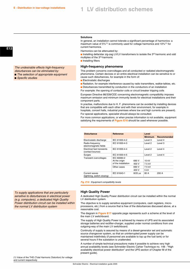
Schneider Electric - Electrical installation guide 2005
E12
E - Distribution in low-voltage installations
SolutionsIn general, an installation cannot tolerate a significant percentage of harmonics: amaximum value of 5%(1) is commonly used for voltage harmonics and 10%(1) forcurrent harmonics.
Harmonics can be attenuated by:c Installing delta/star zig-zag LV/LV transformers to isolate the 3rd harmonic and oddmultiples of the 3rd-harmonicc Installing filters
High-frequency phenomenaThis problem concerns overvoltages and all conducted or radiated electromagneticphenomena. Certain devices or an entire electrical installation can be sensitive to orcause such disturbances, for example in the form of:c Electrostatic dischargesc Radiation, for example interference caused by radio transmitters, walkie-talkies, etc.c Disturbances transmitted by conduction in the conductors of an installationFor example: the opening of contactor coils or circuit breaker tripping coils
European Directive 86/339/CEE concerning electromagnetic compatibility imposesmaximum emission and minimum immunity levels for electrical installations and theircomponent parts.In practise, malfunctions due to H. F. phenomena can be avoided by installing devicesthat are compatible with each other and with their environment, for example inhospitals, concert halls, industrial premises where low and high currents are present).For special applications, specialist should always be consulted.For more common applications, or when precise information is not available, equipmentsatisfying the requirements of Figure E16 should be used whenever possible.
(1) Value of the THD (Total Harmonic Distortion) for voltageand current respectively
The undesirable effects high-frequencydisturbances can be eliminated by:c The selection of appropriate equipmentc Specific studies
Disturbance Reference LevelMinimum Recommended
Electrostatic discharge IEC 61000-4-2 Level 3 Level 4Radio-frequency IEC 61000-4-3 Level 2 Level 3electromagnetic fieldsElectrical fast transients IEC 61000-4-4 Level 2 Level 4(contact bounce)Surges IEC 61000-4-5 Level 2 Level 4Transient overvoltages IEC 60060-2
At the origin 690 V 10 kVof the installation 400 V 7.5 kVOther cases 690 V 7.5 kV
400 V 5 kVCurrent waves IEC 61643-1 8/20 µs 80 A 200 A(lightning, switch closing)
Fig. E16 : Equipment compatibility levels
High Quality PowerA dedicated High Quality Power distribution circuit can be installed within the normalLV distribution system.
The objective is to supply sensitive equipment (computers, cash registers, micro-processors, etc.) from a source that is free of the disturbances discussed above, at areasonable cost.
The diagram in Figure E17 opposite page represents such a scheme at the level ofthe main LV switchboard.
The supply of High Quality Power is achieved by means of UPS and its associatedstorage batteries and rectifier-charger, supplied under normal conditions from oneoutgoing-way of the main LV switchboard.
Continuity of supply is assured by means of a diesel-generator set and automaticsource changeover system, so that an uninterrupted power supply can bemaintained indefinitely (if personnel are available to top up the fuel tank) or forseveral hours if the substation is unattended.
A number of simple technical precautions make it possible to achieve very highannual availability levels (see Schneider Electric Cahier Technique no. 148 : “Highavailability electrical power distribution” and the UPS section of Chapter M of thepresent guide).
To supply applications that are particularlysensitive to disturbances in electrical power(e.g. computers), a dedicated High QualityPower distribution circuit can be installed withinthe normal LV distribution system
1 LV distribution schemes
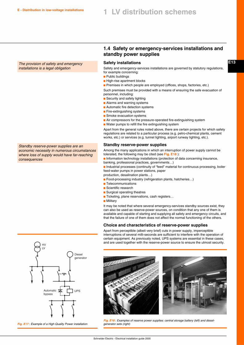
Schneider Electric - Electrical installation guide 2005
E13
E - Distribution in low-voltage installations 1 LV distribution schemes
1.4 Safety or emergency-services installations andstandby power supplies
Safety installationsSafety and emergency-services installations are governed by statutory regulations,for example concerning:c Public buildingsc High-rise apartment blocksc Premises in which people are employed (offices, shops, factories, etc.)
Such premises must be provided with a means of ensuring the safe evacuation ofpersonnel, including:c Security and safety lightingc Alarms and warning systemsc Automatic fire detection systemsc Fire-extinguishing systemsc Smoke evacuation systemsc Air compressors for the pressure-operated fire-extinguishing systemc Water pumps to refill the fire extinguishing system
Apart from the general rules noted above, there are certain projects for which safetyregulations are related to a particular process (e.g. petro-chemical plants, cementworks, etc.) or services (e.g. tunnel lighting, airport runway lighting, etc.).
Standby reserve-power suppliesAmong the many applications in which an interruption of power supply cannot betolerated, the following may be cited (see Fig. E18 ):c Information technology installations (protection of data concerning insurance,banking, professional practices, governments…)c Industrial processes (continuity of “feed” material for continuous processing, boilerfeed-water pumps in power stations, paperproduction, desalination plants…)c Food-processing industry (refrigeration plants, hatcheries…)c Telecommunicationsc Scientific researchc Surgical operating theatresc Ticketing, plane reservations, cash registers…c Military
It may be noted that where several emergency-services standby sources exist, theycan also be used as reserve-power sources, on condition that any one of them isavailable and capable of starting and supplying all safety and emergency circuits, andthat the failure of one of them does not affect the normal functioning of the others.
Choice and characteristics of reserve-power suppliesApart from perceptible (albeit very brief) cuts in power supply, imperceptibleinterruptions of several milli-seconds are sufficient to interfere with the operation ofcertain equipment. As previously noted, UPS systems are essential in these cases,and are used together with the reserve-power source to ensure the utmost security.
Fig. E17 : Example of a High Quality Power installation
HVLV
Diesel
Automaticbypass
generator
UPS
The provision of safety and emergencyinstallations is a legal obligation
Standby reserve-power supplies are aneconomic necessity in numerous circumstanceswhere loss of supply would have far-reachingconsequences
Fig. E18 : Examples of reserve power supplies: central storage battery (left) and diesel-generator sets (right)
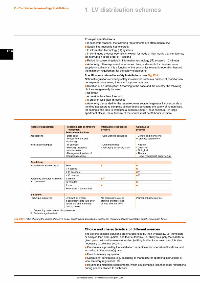
Schneider Electric - Electrical installation guide 2005
E14
E - Distribution in low-voltage installations
Principal specificationsFor economic reasons, the following requirements are often mandatory:c Supply interruption is not tolerated:v In information technology (IT) systemsv In continuous-process operations, except for loads of high inertia that can toleratean interruption in the order of 1 secondc Period for conserving data in information technology (IT) systems: 10 minutesc Autonomy, often expressed as a backup time, is desirable for reserve-powersupplies installations; it is a function of the economics related to operation beyondthe minimum requirement for the safety of personnel
Specifications related to safety installations (see Fig. E19 )National regulations covering safety installations contain a number of conditions tobe respected concerning their electric-power sources:c Duration of an interruption: According to the case and the country, the followingchoices are generally imposed:v No breakv A break of less than 1 secondv A break of less than 15 secondsc Autonomy demanded for the reserve-power source: In general it corresponds tothe time necessary to complete all operations governing the safety of human lives,for example, the time to evacuate a public building (1 hour minimum). In largeapartment blocks, the autonomy of the source must be 36 hours, or more.
Fig. E19 : Table showing the choice of reserve-power supply types according to application requirements and acceptable supply-interruption times
Fields of application Programmable controllers Interruptible sequential ContinuousIT equipment process processTelecommunications
Applications - Data bank - Cold-working sequence - Control and monitoring- Process control and of process parametersmonitoring
Installation examples - IT services - Light machining - Nuclear- Banking, insurance - Packaging assembly chain - Chemical- Administration - Biological- Management system of - Thermalproduction process - Heavy mechanical (high inertia)
ConditionsAllowable duration of break Zero c c
i 1 second c
i 15 seconds c (1)
i 15 minutes c (1)
Autonomy of source minimum 1 minute c (2)
and preferred 20 minutes c
1 hour c c
Permanent if economical
SolutionsTechnique employed UPS with or without No-break generator or Permanent generator set
a generator set to take over start-up and take-overbefore the end of battery of load from the UPSbackup power
(1) Depending on economic circumstances(2) Data-storage time limit
Choice and characteristics of different sourcesThe several possible solutions are characterised by their availability, i.e. immediateor delayed load pick-up time, and their autonomy, i.e. ability to supply the load for agiven period without human intervention (refilling fuel tanks for example). It is alsonecessary to take into account:c Constraints imposed by the installation: in particular for specialised locations, andaccording to the source(s) usedc Complementary equipmentc Operational constraints, e.g. according to manufacturer operating instructions orlocal statutory regulations, etc.c Routine maintenance requirements, which could impose less than ideal restrictionsduring periods allotted to such work
1 LV distribution schemes
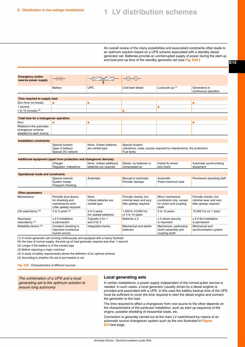
Schneider Electric - Electrical installation guide 2005
E15
E - Distribution in low-voltage installations 1 LV distribution schemes
An overall review of the many possibilities and associated constraints often leads toan optimum solution based on a UPS scheme associated with a standby dieselgenerator set. Batteries provide an uninterrupted supply of power during the start-upand load pick-up time of the standby generator set (see Fig. E20 ).
Fig. E20 : Characteristics of different sources
Emergency and/orreserve power supply
Battery UPS Cold-start diesel Load pick-up (1) Generators incontinuous operation
Time required to supply loadZero time (no break) c c c
1 second c
1 to 10 minutes (5) c
Total time for a changeover operationZero c c c
Related to the automaticchangeover schemeadopted for each source
Installation constraintsSpecial location None. Unless batteries Special location(type of battery) are vented type (vibrations, noise, access required for maintenance, fire protection)Special DC network Fuel tanks
Additional equipment (apart from protection and changeover devices)Charger None. Unless additional Starter, by batteries or Inertia fly wheel Automatic synchronisingRegulator, indications batteries are required compressed air and clutch equipment
Operational mode and constraintsSpecial network Automatic Manual or automatic Automatic Permanent operating staffSystem losses Periodic startups Fixed maximum loadFrequent checking
Other parametersMaintenance Periodic shut-downs None Periodic checks, but Minor mechanical Periodic checks, but
for checking and Unless batteries are minimal wear and very constraints only, except minimal wear and verymaintenance work vented type little upkeep required for clutch and coupling little upkeep requiredLittle upkeep required shaft
Life expectancy (3) 4 to 5 years (2) 4 to 5 years 1,000 to 10,000 hrs 5 to 10 years 10,000 hrs (or 1 year)(for sealed batteries) or 5 to 10 years
Necessary x 2 if installation Typically 2 for 1 Batteries x 2 x 2 where security x 2 if the installationredundancy (4) is permanent and 3 for 2 is important is permanentReliability factors (4) Constant checking is Integrated checks Mechanical and starter Mechanical, particularly Mechanical and
important (numerous batteries clutch assembly and synchronisation systemhuman errors) coupling shaft
(1) A motor-generator set running continuously and equipped with a heavy flywheelOn the loss of normal supply, the pick-up of load generally requires less than 1 second(2) Longer if the battery is of the vented type(3) Before requiring a major overhaul(4) A study of safety requirements allows the definition of an optimal scheme(5) According to whether the set is pre-heated or not
GM
Local generating setsIn certain installations, a power supply independent of the normal public service isneeded. In such cases, a local generator (usually driven by a diesel engine) isprovided and associated with a UPS. In this case the battery backup time of the UPSmust be sufficient to cover the time required to start the diesel engine and connectthe generator to the load.
The time required to effect a changeover from one source to the other depends onthe characteristics of the particular installation, such as start-up sequence of theengine, possible shedding of inessential loads, etc.
Connection is generally carried out at the main LV switchboard by means of anautomatic source changeover system such as the one illustrated in FigureE21next page.
The combination of a UPS and a localgenerating set is the optimum solution toensure long autonomy
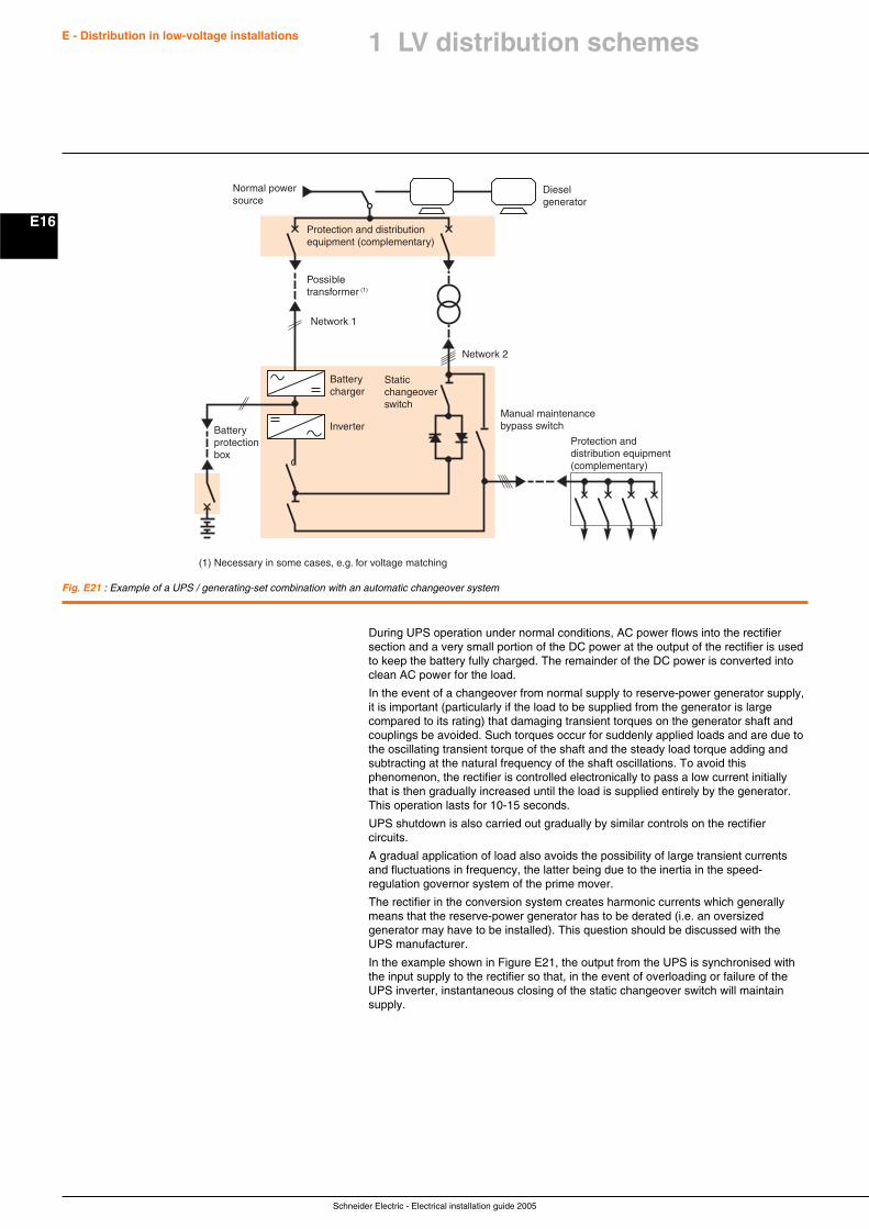
Schneider Electric - Electrical installation guide 2005
E - Distribution in low-voltage installations
E16
1 LV distribution schemes
During UPS operation under normal conditions, AC power flows into the rectifiersection and a very small portion of the DC power at the output of the rectifier is usedto keep the battery fully charged. The remainder of the DC power is converted intoclean AC power for the load.
In the event of a changeover from normal supply to reserve-power generator supply,it is important (particularly if the load to be supplied from the generator is largecompared to its rating) that damaging transient torques on the generator shaft andcouplings be avoided. Such torques occur for suddenly applied loads and are due tothe oscillating transient torque of the shaft and the steady load torque adding andsubtracting at the natural frequency of the shaft oscillations. To avoid thisphenomenon, the rectifier is controlled electronically to pass a low current initiallythat is then gradually increased until the load is supplied entirely by the generator.This operation lasts for 10-15 seconds.
UPS shutdown is also carried out gradually by similar controls on the rectifiercircuits.
A gradual application of load also avoids the possibility of large transient currentsand fluctuations in frequency, the latter being due to the inertia in the speed-regulation governor system of the prime mover.
The rectifier in the conversion system creates harmonic currents which generallymeans that the reserve-power generator has to be derated (i.e. an oversizedgenerator may have to be installed). This question should be discussed with theUPS manufacturer.
In the example shown in Figure E21, the output from the UPS is synchronised withthe input supply to the rectifier so that, in the event of overloading or failure of theUPS inverter, instantaneous closing of the static changeover switch will maintainsupply.
Fig. E21 : Example of a UPS / generating-set combination with an automatic changeover system
Protection and distributionequipment (complementary)
Possibletransformer (1)
Network 2
Staticchangeoverswitch
Batterycharger
InverterBatteryprotectionbox
Network 1
Dieselgenerator
(1) Necessary in some cases, e.g. for voltage matching
Normal powersource
Protection anddistribution equipment(complementary)
Manual maintenancebypass switch
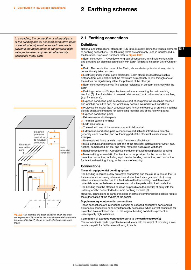
Schneider Electric - Electrical installation guide 2005
E17
E - Distribution in low-voltage installations 2 Earthing schemes
2.1 Earthing connections
DefinitionsNational and international standards (IEC 60364) clearly define the various elementsof earthing connections. The following terms are commonly used in industry and inthe literature. Bracketed numbers refer to Figure E22 :c Earth electrode (1): A conductor or group of conductors in intimate contact with,and providing an electrical connection with Earth (cf details in section 2.6 of ChapterE.)c Earth: The conductive mass of the Earth, whose electric potential at any point isconventionally taken as zeroc Electrically independent earth electrodes: Earth electrodes located at such adistance from one another that the maximum current likely to flow through one ofthem does not significantly affect the potential of the other(s)c Earth electrode resistance: The contact resistance of an earth electrode with theEarthc Earthing conductor (2): A protective conductor connecting the main earthingterminal (6) of an installation to an earth electrode (1) or to other means of earthing(e.g. TN systems);c Exposed-conductive-part: A conductive part of equipment which can be touchedand which is not a live part, but which may become live under fault conditionsc Protective conductor (3): A conductor used for some measures of protection againstelectric shock and intended for connecting together any of the following parts:v Exposed-conductive-partsv Extraneous-conductive-partsv The main earthing terminalv Earth electrode(s)v The earthed point of the source or an artificial neutral
c Extraneous-conductive-part: A conductive part liable to introduce a potential,generally earth potential, and not forming part of the electrical installation (4). Forexample:v Non-insulated floors or walls, metal framework of buildingsv Metal conduits and pipework (not part of the electrical installation) for water, gas,heating, compressed-air, etc. and metal materials associated with them
c Bonding conductor (5): A protective conductor providing equipotential bondingc Main earthing terminal (6): The terminal or bar provided for the connection ofprotective conductors, including equipotential bonding conductors, and conductorsfor functional earthing, if any, to the means of earthing.
ConnectionsThe main equipotential bonding systemThe bonding is carried out by protective conductors and the aim is to ensure that, inthe event of an incoming extraneous conductor (such as a gas pipe, etc.) beingraised to some potential due to a fault external to the building, no difference ofpotential can occur between extraneous-conductive-parts within the installation.
The bonding must be effected as close as possible to the point(s) of entry into thebuilding, and be connected to the main earthing terminal (6).
However, connections to earth of metallic sheaths of communications cables requirethe authorisation of the owners of the cables.
Supplementary equipotential connectionsThese connections are intended to connect all exposed-conductive-parts and allextraneous-conductive-parts simultaneously accessible, when correct conditions forprotection have not been met, i.e. the original bonding conductors present anunacceptably high resistance.
Connection of exposed-conductive-parts to the earth electrode(s)The connection is made by protective conductors with the object of providing a low-resistance path for fault currents flowing to earth.
In a building, the connection of all metal partsof the building and all exposed conductive partsof electrical equipment to an earth electrodeprevents the appearance of dangerously highvoltages between any two simultaneouslyaccessible metal parts
Fig. E22 : An example of a block of flats in which the mainearthing terminal (6) provides the main equipotential connection;the removable link (7) allows an earth-electrode-resistancecheck
Branchedprotectiveconductorsto individualconsumers
Extraneousconductiveparts
3
3
3
Mainprotectiveconductor
12
7
6
5
5
5
4
4
Heating
Water
Gas
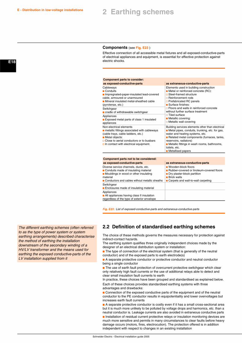
Schneider Electric - Electrical installation guide 2005
E18
E - Distribution in low-voltage installations
Components (see Fig. E23 )
Effective connection of all accessible metal fixtures and all exposed-conductive-partsof electrical appliances and equipment, is essential for effective protection againstelectric shocks.
Fig. E23 : List of exposed-conductive-parts and extraneous-conductive-parts
Component parts to consider:as exposed-conductive-parts as extraneous-conductive-partsCableways Elements used in building constructionc Conduits c Metal or reinforced concrete (RC):c Impregnated-paper-insulated lead-covered v Steel-framed structurecable, armoured or unarmoured v Reinforcement rodsc Mineral insulated metal-sheathed cable v Prefabricated RC panels(pyrotenax, etc.) c Surface finishes:Switchgear v Floors and walls in reinforced concretec cradle of withdrawable switchgear without further surface treatment
Appliances v Tiled surface
c Exposed metal parts of class 1 insulated c Metallic covering:
appliances v Metallic wall covering
Non-electrical elements Building services elements other than electricalc metallic fittings associated with cableways c Metal pipes, conduits, trunking, etc. for gas,(cable trays, cable ladders, etc.) water and heating systems, etc.c Metal objects: c Related metal components (furnaces, tanks,v Close to aerial conductors or to busbars reservoirs, radiators)v In contact with electrical equipment. c Metallic fittings in wash rooms, bathrooms,
toilets, etc.c Metallised papers
Component parts not to be considered:as exposed-conductive-parts as extraneous-conductive-partsDiverse service channels, ducts, etc. c Wooden-block floorsc Conduits made of insulating material c Rubber-covered or linoleum-covered floorsc Mouldings in wood or other insulating c Dry plaster-block partitionmaterial c Brick wallsc Conductors and cables without metallic sheaths c Carpets and wall-to-wall carpetingSwitchgearc Enclosures made of insulating materialAppliancesc All appliances having class II insulationregardless of the type of exterior envelope
2.2 Definition of standardised earthing schemes
The choice of these methods governs the measures necessary for protection againstindirect-contact hazards.The earthing system qualifies three originally independent choices made by thedesigner of an electrical distribution system or installation:c The type of connection of the electrical system (that is generally of the neutralconductor) and of the exposed parts to earth electrode(s)c A separate protective conductor or protective conductor and neutral conductorbeing a single conductorc The use of earth fault protection of overcurrent protective switchgear which clearonly relatively high fault currents or the use of additional relays able to detect andclear small insulation fault currents to earthIn practice, these choices have been grouped and standardised as explained below.
Each of these choices provides standardised earthing systems with threeadvantages and drawbacks:c Connection of the exposed conductive parts of the equipment and of the neutralconductor to the PE conductor results in equipotentiality and lower overvoltages butincreases earth fault currentsc A separate protective conductor is costly even if it has a small cross-sectional areabut it is much more unlikely to be polluted by voltage drops and harmonics, etc. than aneutral conductor is. Leakage currents are also avoided in extraneous conductive partsc Installation of residual current protective relays or insulation monitoring devices aremuch more sensitive and permits in many circumstances to clear faults before heavydamage occurs (motors, fires, electrocution). The protection offered is in additionindependent with respect to changes in an existing installation
The different earthing schemes (often referredto as the type of power system or systemearthing arrangements) described characterisethe method of earthing the installationdownstream of the secondary winding of aHV/LV transformer and the means used forearthing the exposed conductive-parts of theLV installation supplied from it
2 Earthing schemes

Schneider Electric - Electrical installation guide 2005
E19
E - Distribution in low-voltage installations 2 Earthing schemes
TT system (earthed neutral) (see Fig. E24 )
One point at the supply source is connected directly to earth. All exposed- andextraneous-conductive-parts are connected to a separate earth electrode at theinstallation. This electrode may or may not be electrically independent of the sourceelectrode. The two zones of influence may overlap without affecting the operation ofprotective devices.
TN systems (exposed conductive parts connected to theneutral)The source is earthed as for the TT system (above). In the installation, all exposed-and extraneous-conductive-parts are connected to the neutral conductor. The severalversions of TN systems are shown below.
TN-C system (see Fig. E25 )The neutral conductor is also used as a protective conductor and is referred to as aPEN (Protective Earth and Neutral) conductor. This system is not permitted forconductors of less than 10 mm2 or for portable equipment.The TN-C system requires an effective equipotential environment within theinstallation with dispersed earth electrodes spaced as regularly as possible since thePEN conductor is both the neutral conductor and at the same time carries phaseunbalance currents as well as 3rd order harmonic currents (and their multiples).The PEN conductor must therefore be connected to a number of earth electrodes inthe installation.Since the neutral conductor is also the protective conductor, any break in theconductor represents a danger to life and property.For this reason, electrical utilities impose the installation of residual current devices(RCDs) at the service connection points of private subscribers.If an RCD is not installed, a low earthing resistance (no more than 2 ohms) isrequired to limit the touch voltage to 50 V in the event of a fault.
TN-S system (see Fig. E26 )The TN-S system (5 wires) is obligatory for circuits with cross-sectional areas lessthan 10 mm2 for portable equipment.The protective conductor and the neutral conductor are separate. On undergroundcable systems where lead-sheathed cables exist, the protective conductor isgenerally the lead sheath. The use of separate PE and N conductors (5 wires) isobligatory for circuits with cross-sectional areas less than 10 mm2 for portableequipment.
TN-C-S system (see Fig. E27 below and Fig. E28 next page)Caution: In the TN-C system, the “protective conductor” function has priority over the“neutral function”. In particular, a PEN conductor must always be connected to theearthing terminal of a load and a jumper is used to connect this terminal to theneutral terminal.The TN-C and TN-S systems can be used in the same installation. In the TN-C-Ssystem, the TN-C (4 wires) system must never be used downstream of the TN-S(5 wires) system, since any accidental interruption in the neutral on the upstreampart would lead to an interruption in the protective conductor in the downstream partand therefore a danger.
L1L2L3NPE
Rn
Neutral
Earth
Exposed conductive parts
Earth
L1L2L3PEN
Rn
Neutral
Earth
Exposed conductive parts
Earth
L1L2L3NPE
Rn
Fig. E24 : TT System
Fig. E25 : TN-C system
Fig. E26 : TN-S system
L1L2L3NPE
Bad Bad
16 mm2 6 mm2 16 mm2 16 mm2
PEN
TN-C scheme not permitted downstream of TN-S scheme
5 x 50 mm2
PENPE
Fig. E27 : TN-C-S system
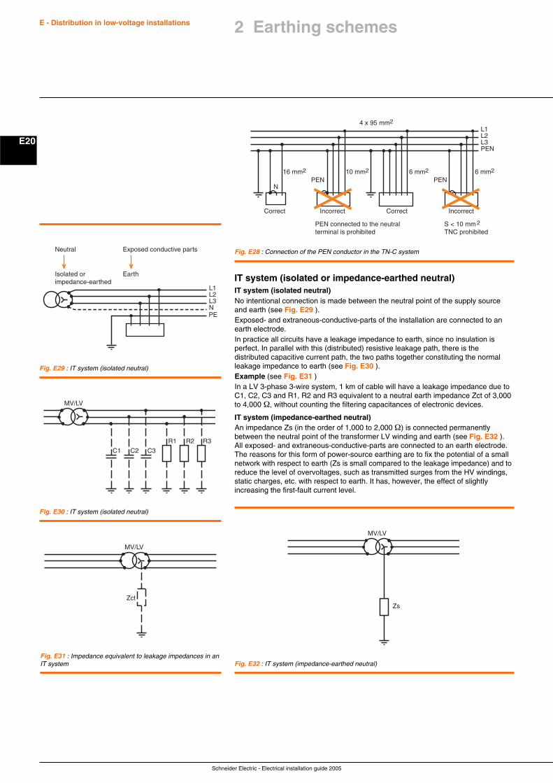
Schneider Electric - Electrical installation guide 2005
E20
E - Distribution in low-voltage installations
IT system (isolated or impedance-earthed neutral)IT system (isolated neutral)No intentional connection is made between the neutral point of the supply sourceand earth (see Fig. E29 ).Exposed- and extraneous-conductive-parts of the installation are connected to anearth electrode.In practice all circuits have a leakage impedance to earth, since no insulation isperfect. In parallel with this (distributed) resistive leakage path, there is thedistributed capacitive current path, the two paths together constituting the normalleakage impedance to earth (see Fig. E30 ).Example (see Fig. E31 )In a LV 3-phase 3-wire system, 1 km of cable will have a leakage impedance due toC1, C2, C3 and R1, R2 and R3 equivalent to a neutral earth impedance Zct of 3,000to 4,000 Ω, without counting the filtering capacitances of electronic devices.
IT system (impedance-earthed neutral)An impedance Zs (in the order of 1,000 to 2,000 Ω) is connected permanentlybetween the neutral point of the transformer LV winding and earth (see Fig. E32 ).All exposed- and extraneous-conductive-parts are connected to an earth electrode.The reasons for this form of power-source earthing are to fix the potential of a smallnetwork with respect to earth (Zs is small compared to the leakage impedance) and toreduce the level of overvoltages, such as transmitted surges from the HV windings,static charges, etc. with respect to earth. It has, however, the effect of slightlyincreasing the first-fault current level.
Fig. E28 : Connection of the PEN conductor in the TN-C system
L1L2L3PEN
16 mm2 10 mm2 6 mm2 6 mm2
PEN
2
4 x 95 mm2
Correct Incorrect Correct Incorrect
PEN connected to the neutralterminal is prohibited
S < 10 mmTNC prohibited
NPEN
Fig. E29 : IT system (isolated neutral)
Fig. E30 : IT system (isolated neutral)
Fig. E31 : Impedance equivalent to leakage impedances in anIT system Fig. E32 : IT system (impedance-earthed neutral)
L1L2L3NPE
Neutral
Isolated orimpedance-earthed
Exposed conductive parts
Earth
R3R2R1
C3C2C1
MV/LV
Zct
MV/LV
MV/LV
Zs
2 Earthing schemes
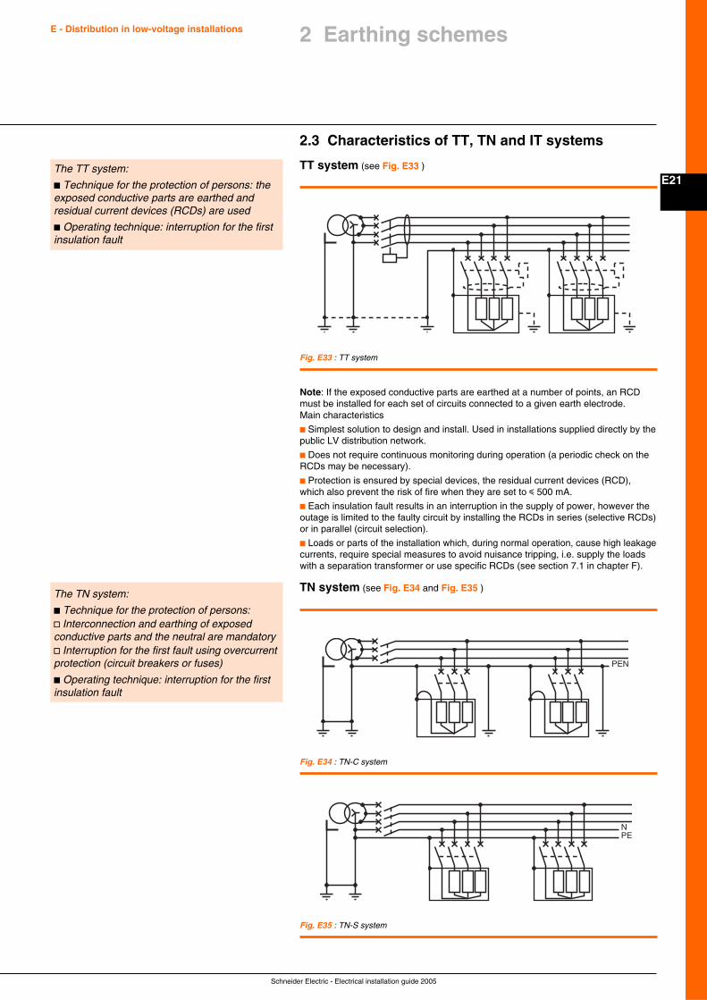
Schneider Electric - Electrical installation guide 2005
E21
E - Distribution in low-voltage installations 2 Earthing schemes
2.3 Characteristics of TT, TN and IT systems
TT system (see Fig. E33 )The TT system:
c Technique for the protection of persons: theexposed conductive parts are earthed andresidual current devices (RCDs) are used
c Operating technique: interruption for the firstinsulation fault
The TN system:
c Technique for the protection of persons:v Interconnection and earthing of exposedconductive parts and the neutral are mandatoryv Interruption for the first fault using overcurrentprotection (circuit breakers or fuses)
c Operating technique: interruption for the firstinsulation fault
Fig. E33 : TT system
Note: If the exposed conductive parts are earthed at a number of points, an RCDmust be installed for each set of circuits connected to a given earth electrode.Main characteristics
c Simplest solution to design and install. Used in installations supplied directly by thepublic LV distribution network.
c Does not require continuous monitoring during operation (a periodic check on theRCDs may be necessary).
c Protection is ensured by special devices, the residual current devices (RCD),which also prevent the risk of fire when they are set to i 500 mA.
c Each insulation fault results in an interruption in the supply of power, however theoutage is limited to the faulty circuit by installing the RCDs in series (selective RCDs)or in parallel (circuit selection).
c Loads or parts of the installation which, during normal operation, cause high leakagecurrents, require special measures to avoid nuisance tripping, i.e. supply the loadswith a separation transformer or use specific RCDs (see section 7.1 in chapter F).
TN system (see Fig. E34 and Fig. E35 )
Fig. E35 : TN-S system
Fig. E34 : TN-C system
PEN
NPE
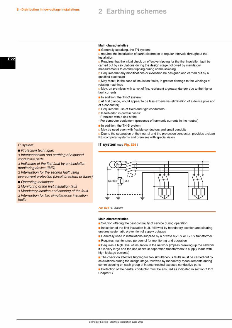
Schneider Electric - Electrical installation guide 2005
E22
E - Distribution in low-voltage installations
Main characteristicsc Generally speaking, the TN system:v requires the installation of earth electrodes at regular intervals throughout theinstallationv Requires that the initial check on effective tripping for the first insulation fault becarried out by calculations during the design stage, followed by mandatorymeasurements to confirm tripping during commissioningv Requires that any modifications or extension be designed and carried out by aqualified electricianv May result, in the case of insulation faults, in greater damage to the windings ofrotating machinesv May, on premises with a risk of fire, represent a greater danger due to the higherfault currents
c In addition, the TN-C system:v At first glance, would appear to be less expensive (elimination of a device pole andof a conductor)v Requires the use of fixed and rigid conductorsv Is forbidden in certain cases:- Premises with a risk of fire- For computer equipment (presence of harmonic currents in the neutral)
c In addition, the TN-S system:v May be used even with flexible conductors and small conduitsv Due to the separation of the neutral and the protection conductor, provides a cleanPE (computer systems and premises with special risks)
IT system (see Fig. E36 )IT system:
c Protection technique:v Interconnection and earthing of exposedconductive partsv Indication of the first fault by an insulationmonitoring device (IMD)v Interruption for the second fault usingovercurrent protection (circuit breakers or fuses)
c Operating technique:v Monitoring of the first insulation faultv Mandatory location and clearing of the faultv Interruption for two simultaneous insulationfaults
Fig. E36 : IT system
IMDCardew
Main characteristicsc Solution offering the best continuity of service during operation
c Indication of the first insulation fault, followed by mandatory location and clearing,ensures systematic prevention of supply outages
c Generally used in installations supplied by a private MV/LV or LV/LV transformer
c Requires maintenance personnel for monitoring and operation
c Requires a high level of insulation in the network (implies breaking up the networkif it is very large and the use of circuit-separation transformers to supply loads withhigh leakage currents)
c The check on effective tripping for two simultaneous faults must be carried out bycalculations during the design stage, followed by mandatory measurements duringcommissioning on each group of interconnected exposed conductive parts
c Protection of the neutral conductor must be ensured as indicated in section 7.2 ofChapter G
2 Earthing schemes
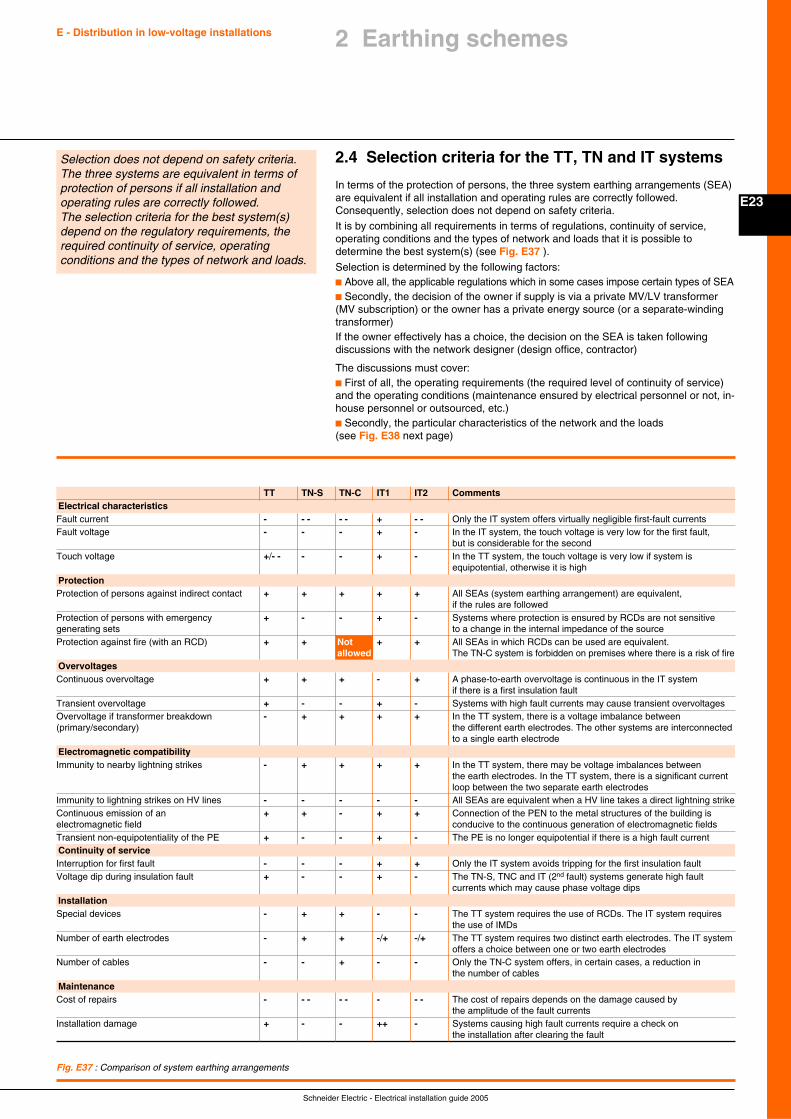
Schneider Electric - Electrical installation guide 2005
E23
E - Distribution in low-voltage installations 2 Earthing schemes
2.4 Selection criteria for the TT, TN and IT systems
In terms of the protection of persons, the three system earthing arrangements (SEA)are equivalent if all installation and operating rules are correctly followed.Consequently, selection does not depend on safety criteria.
It is by combining all requirements in terms of regulations, continuity of service,operating conditions and the types of network and loads that it is possible todetermine the best system(s) (see Fig. E37 ).
Selection is determined by the following factors:c Above all, the applicable regulations which in some cases impose certain types of SEAc Secondly, the decision of the owner if supply is via a private MV/LV transformer(MV subscription) or the owner has a private energy source (or a separate-windingtransformer)If the owner effectively has a choice, the decision on the SEA is taken followingdiscussions with the network designer (design office, contractor)
The discussions must cover:c First of all, the operating requirements (the required level of continuity of service)and the operating conditions (maintenance ensured by electrical personnel or not, in-house personnel or outsourced, etc.)c Secondly, the particular characteristics of the network and the loads(see Fig. E38 next page)
Selection does not depend on safety criteria.The three systems are equivalent in terms ofprotection of persons if all installation andoperating rules are correctly followed.The selection criteria for the best system(s)depend on the regulatory requirements, therequired continuity of service, operatingconditions and the types of network and loads.
Fig. E37 : Comparison of system earthing arrangements
TT TN-S TN-C IT1 IT2 CommentsElectrical characteristicsFault current - - - - - + - - Only the IT system offers virtually negligible first-fault currentsFault voltage - - - + - In the IT system, the touch voltage is very low for the first fault,
but is considerable for the secondTouch voltage +/- - - - + - In the TT system, the touch voltage is very low if system is
equipotential, otherwise it is highProtectionProtection of persons against indirect contact + + + + + All SEAs (system earthing arrangement) are equivalent,
if the rules are followedProtection of persons with emergency + - - + - Systems where protection is ensured by RCDs are not sensitivegenerating sets to a change in the internal impedance of the sourceProtection against fire (with an RCD) + + Not + + All SEAs in which RCDs can be used are equivalent.
allowed The TN-C system is forbidden on premises where there is a risk of fireOvervoltagesContinuous overvoltage + + + - + A phase-to-earth overvoltage is continuous in the IT system
if there is a first insulation faultTransient overvoltage + - - + - Systems with high fault currents may cause transient overvoltagesOvervoltage if transformer breakdown - + + + + In the TT system, there is a voltage imbalance between(primary/secondary) the different earth electrodes. The other systems are interconnected
to a single earth electrodeElectromagnetic compatibilityImmunity to nearby lightning strikes - + + + + In the TT system, there may be voltage imbalances between
the earth electrodes. In the TT system, there is a significant currentloop between the two separate earth electrodes
Immunity to lightning strikes on HV lines - - - - - All SEAs are equivalent when a HV line takes a direct lightning strikeContinuous emission of an + + - + + Connection of the PEN to the metal structures of the building iselectromagnetic field conducive to the continuous generation of electromagnetic fieldsTransient non-equipotentiality of the PE + - - + - The PE is no longer equipotential if there is a high fault currentContinuity of serviceInterruption for first fault - - - + + Only the IT system avoids tripping for the first insulation faultVoltage dip during insulation fault + - - + - The TN-S, TNC and IT (2nd fault) systems generate high fault
currents which may cause phase voltage dipsInstallationSpecial devices - + + - - The TT system requires the use of RCDs. The IT system requires
the use of IMDsNumber of earth electrodes - + + -/+ -/+ The TT system requires two distinct earth electrodes. The IT system
offers a choice between one or two earth electrodesNumber of cables - - + - - Only the TN-C system offers, in certain cases, a reduction in
the number of cablesMaintenanceCost of repairs - - - - - - - - The cost of repairs depends on the damage caused by
the amplitude of the fault currentsInstallation damage + - - ++ - Systems causing high fault currents require a check on
the installation after clearing the fault
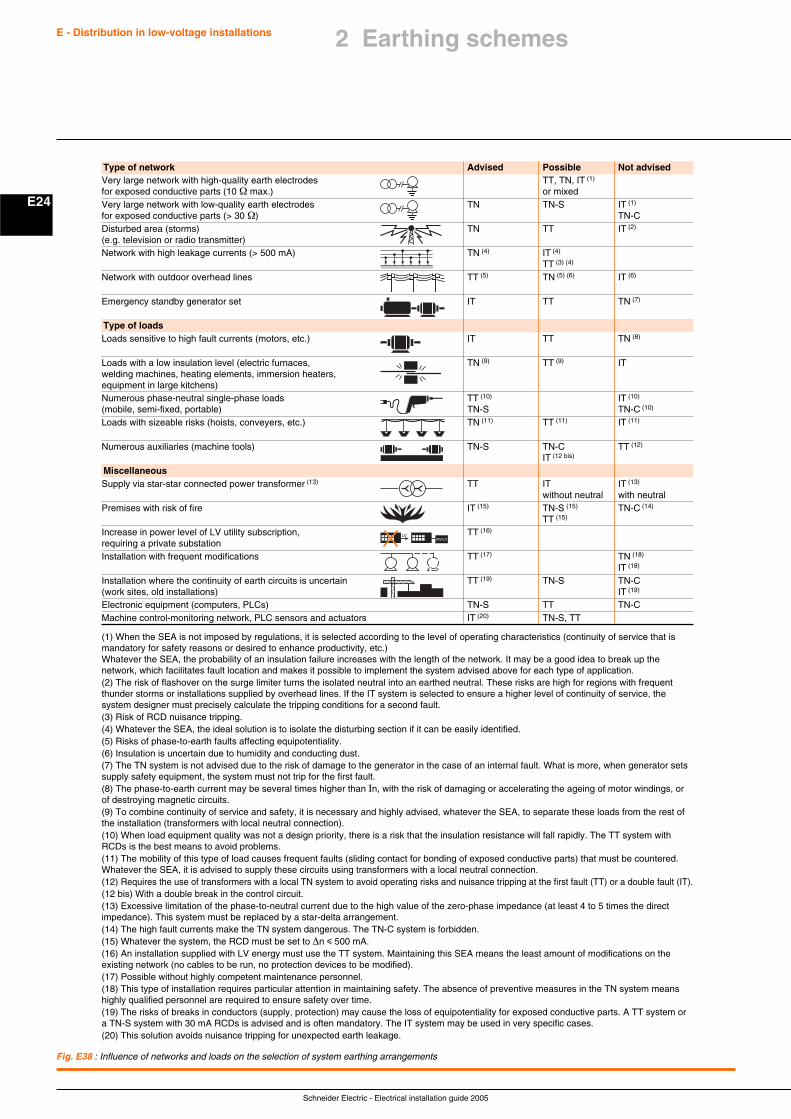
Schneider Electric - Electrical installation guide 2005
E24
E - Distribution in low-voltage installations
Fig. E38 : Influence of networks and loads on the selection of system earthing arrangements
(1) When the SEA is not imposed by regulations, it is selected according to the level of operating characteristics (continuity of service that ismandatory for safety reasons or desired to enhance productivity, etc.)Whatever the SEA, the probability of an insulation failure increases with the length of the network. It may be a good idea to break up thenetwork, which facilitates fault location and makes it possible to implement the system advised above for each type of application.(2) The risk of flashover on the surge limiter turns the isolated neutral into an earthed neutral. These risks are high for regions with frequentthunder storms or installations supplied by overhead lines. If the IT system is selected to ensure a higher level of continuity of service, thesystem designer must precisely calculate the tripping conditions for a second fault.(3) Risk of RCD nuisance tripping.(4) Whatever the SEA, the ideal solution is to isolate the disturbing section if it can be easily identified.(5) Risks of phase-to-earth faults affecting equipotentiality.(6) Insulation is uncertain due to humidity and conducting dust.(7) The TN system is not advised due to the risk of damage to the generator in the case of an internal fault. What is more, when generator setssupply safety equipment, the system must not trip for the first fault.(8) The phase-to-earth current may be several times higher than In, with the risk of damaging or accelerating the ageing of motor windings, orof destroying magnetic circuits.(9) To combine continuity of service and safety, it is necessary and highly advised, whatever the SEA, to separate these loads from the rest ofthe installation (transformers with local neutral connection).(10) When load equipment quality was not a design priority, there is a risk that the insulation resistance will fall rapidly. The TT system withRCDs is the best means to avoid problems.(11) The mobility of this type of load causes frequent faults (sliding contact for bonding of exposed conductive parts) that must be countered.Whatever the SEA, it is advised to supply these circuits using transformers with a local neutral connection.(12) Requires the use of transformers with a local TN system to avoid operating risks and nuisance tripping at the first fault (TT) or a double fault (IT).(12 bis) With a double break in the control circuit.(13) Excessive limitation of the phase-to-neutral current due to the high value of the zero-phase impedance (at least 4 to 5 times the directimpedance). This system must be replaced by a star-delta arrangement.(14) The high fault currents make the TN system dangerous. The TN-C system is forbidden.(15) Whatever the system, the RCD must be set to ∆n i 500 mA.(16) An installation supplied with LV energy must use the TT system. Maintaining this SEA means the least amount of modifications on theexisting network (no cables to be run, no protection devices to be modified).(17) Possible without highly competent maintenance personnel.(18) This type of installation requires particular attention in maintaining safety. The absence of preventive measures in the TN system meanshighly qualified personnel are required to ensure safety over time.(19) The risks of breaks in conductors (supply, protection) may cause the loss of equipotentiality for exposed conductive parts. A TT system ora TN-S system with 30 mA RCDs is advised and is often mandatory. The IT system may be used in very specific cases.(20) This solution avoids nuisance tripping for unexpected earth leakage.
Type of network Advised Possible Not advisedVery large network with high-quality earth electrodes TT, TN, IT (1)
for exposed conductive parts (10 Ω max.) or mixedVery large network with low-quality earth electrodes TN TN-S IT (1)
for exposed conductive parts (> 30 Ω) TN-CDisturbed area (storms) TN TT IT (2)
(e.g. television or radio transmitter)Network with high leakage currents (> 500 mA) TN (4) IT (4)
TT (3) (4)
Network with outdoor overhead lines TT (5) TN (5) (6) IT (6)
Emergency standby generator set IT TT TN (7)
Type of loadsLoads sensitive to high fault currents (motors, etc.) IT TT TN (8)
Loads with a low insulation level (electric furnaces, TN (9) TT (9) ITwelding machines, heating elements, immersion heaters,equipment in large kitchens)Numerous phase-neutral single-phase loads TT (10) IT (10)
(mobile, semi-fixed, portable) TN-S TN-C (10)
Loads with sizeable risks (hoists, conveyers, etc.) TN (11) TT (11) IT (11)
Numerous auxiliaries (machine tools) TN-S TN-C TT (12)
IT (12 bis)
MiscellaneousSupply via star-star connected power transformer (13) TT IT IT (13)
without neutral with neutralPremises with risk of fire IT (15) TN-S (15) TN-C (14)
TT (15)
Increase in power level of LV utility subscription, TT (16)
requiring a private substationInstallation with frequent modifications TT (17) TN (18)
IT (18)
Installation where the continuity of earth circuits is uncertain TT (19) TN-S TN-C(work sites, old installations) IT (19)
Electronic equipment (computers, PLCs) TN-S TT TN-CMachine control-monitoring network, PLC sensors and actuators IT (20) TN-S, TT
MV/LVLV
2 Earthing schemes
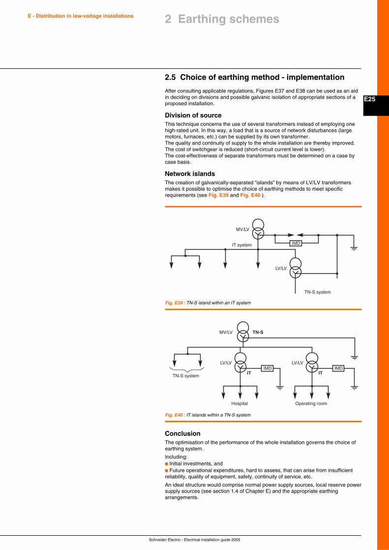
Schneider Electric - Electrical installation guide 2005
E25
E - Distribution in low-voltage installations 2 Earthing schemes
2.5 Choice of earthing method - implementation
After consulting applicable regulations, Figures E37 and E38 can be used as an aidin deciding on divisions and possible galvanic isolation of appropriate sections of aproposed installation.
Division of sourceThis technique concerns the use of several transformers instead of employing onehigh-rated unit. In this way, a load that is a source of network disturbances (largemotors, furnaces, etc.) can be supplied by its own transformer.The quality and continuity of supply to the whole installation are thereby improved.The cost of switchgear is reduced (short-circuit current level is lower).The cost-effectiveness of separate transformers must be determined on a case bycase basis.
Network islandsThe creation of galvanically-separated “islands” by means of LV/LV transformersmakes it possible to optimise the choice of earthing methods to meet specificrequirements (see Fig. E39 and Fig. E40 ).
Fig. E39 : TN-S island within an IT system
Fig. E40 : IT islands within a TN-S system
IMDIT system
LV/LV
MV/LV
TN-S system
TN-S system
LV/LV
MV/LV TN-S
Operating room
LV/LV
IT IT
Hospital
IMD IMD
ConclusionThe optimisation of the performance of the whole installation governs the choice ofearthing system.
Including:c Initial investments, andc Future operational expenditures, hard to assess, that can arise from insufficientreliability, quality of equipment, safety, continuity of service, etc.
An ideal structure would comprise normal power supply sources, local reserve powersupply sources (see section 1.4 of Chapter E) and the appropriate earthingarrangements.
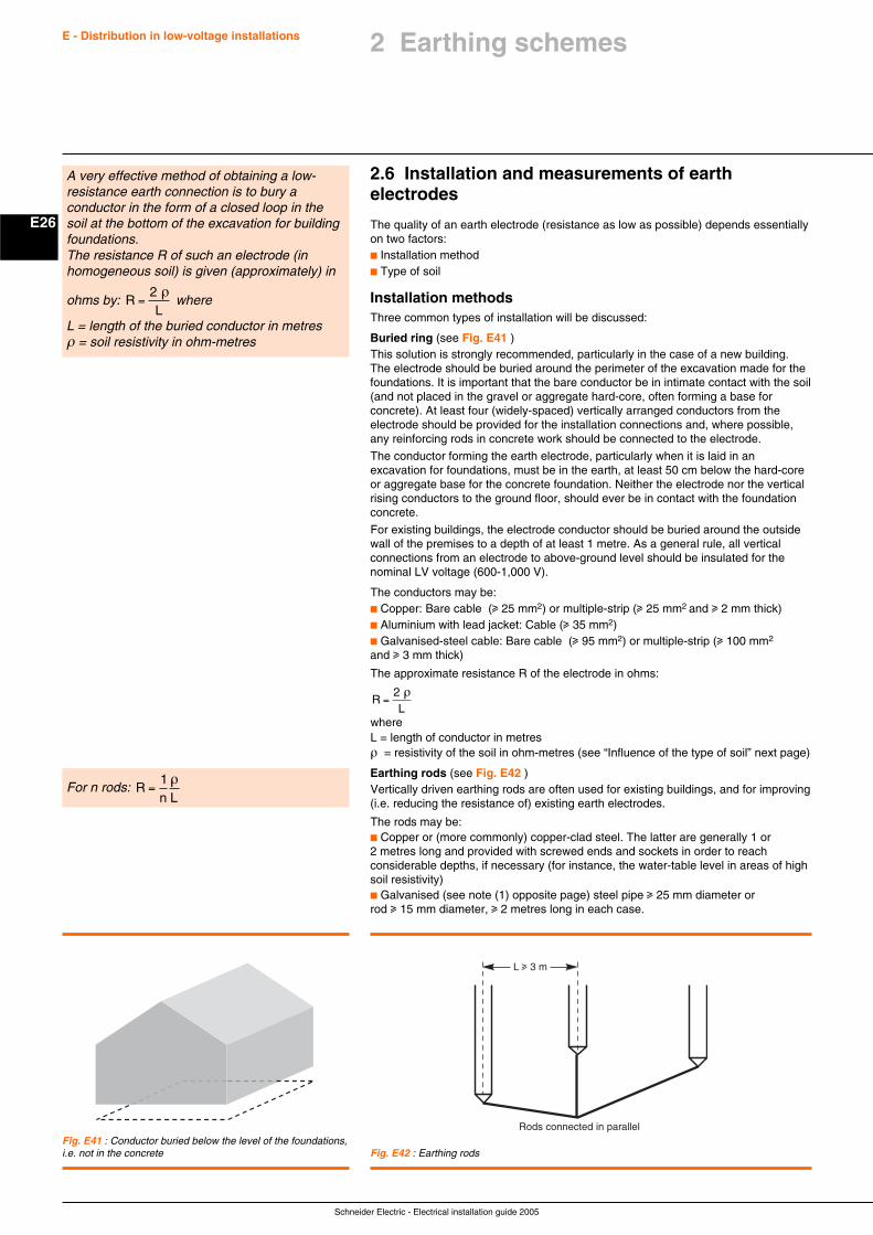
Schneider Electric - Electrical installation guide 2005
E26
E - Distribution in low-voltage installations
2.6 Installation and measurements of earthelectrodes
The quality of an earth electrode (resistance as low as possible) depends essentiallyon two factors:c Installation methodc Type of soil
Installation methodsThree common types of installation will be discussed:
Buried ring (see Fig. E41 )This solution is strongly recommended, particularly in the case of a new building.The electrode should be buried around the perimeter of the excavation made for thefoundations. It is important that the bare conductor be in intimate contact with the soil(and not placed in the gravel or aggregate hard-core, often forming a base forconcrete). At least four (widely-spaced) vertically arranged conductors from theelectrode should be provided for the installation connections and, where possible,any reinforcing rods in concrete work should be connected to the electrode.
The conductor forming the earth electrode, particularly when it is laid in anexcavation for foundations, must be in the earth, at least 50 cm below the hard-coreor aggregate base for the concrete foundation. Neither the electrode nor the verticalrising conductors to the ground floor, should ever be in contact with the foundationconcrete.
For existing buildings, the electrode conductor should be buried around the outsidewall of the premises to a depth of at least 1 metre. As a general rule, all verticalconnections from an electrode to above-ground level should be insulated for thenominal LV voltage (600-1,000 V).
The conductors may be:c Copper: Bare cable (u 25 mm2) or multiple-strip (u 25 mm2 and u 2 mm thick)c Aluminium with lead jacket: Cable (u 35 mm2)c Galvanised-steel cable: Bare cable (u 95 mm2) or multiple-strip (u 100 mm2
and u 3 mm thick)
The approximate resistance R of the electrode in ohms:
RL
=2 ρ
whereL = length of conductor in metresρ = resistivity of the soil in ohm-metres (see “Influence of the type of soil” next page)
Earthing rods (see Fig. E42 )Vertically driven earthing rods are often used for existing buildings, and for improving(i.e. reducing the resistance of) existing earth electrodes.
The rods may be:c Copper or (more commonly) copper-clad steel. The latter are generally 1 or2 metres long and provided with screwed ends and sockets in order to reachconsiderable depths, if necessary (for instance, the water-table level in areas of highsoil resistivity)c Galvanised (see note (1) opposite page) steel pipe u 25 mm diameter orrod u 15 mm diameter, u 2 metres long in each case.
A very effective method of obtaining a low-resistance earth connection is to bury aconductor in the form of a closed loop in thesoil at the bottom of the excavation for buildingfoundations.The resistance R of such an electrode (inhomogeneous soil) is given (approximately) in
ohms by: RL
=2 ρ
where
L = length of the buried conductor in metresρ = soil resistivity in ohm-metres
Fig. E41 : Conductor buried below the level of the foundations,i.e. not in the concrete
For n rods: Rn L
=1 ρ
Fig. E42 : Earthing rods
Rods connected in parallel
L u 3 m
2 Earthing schemes
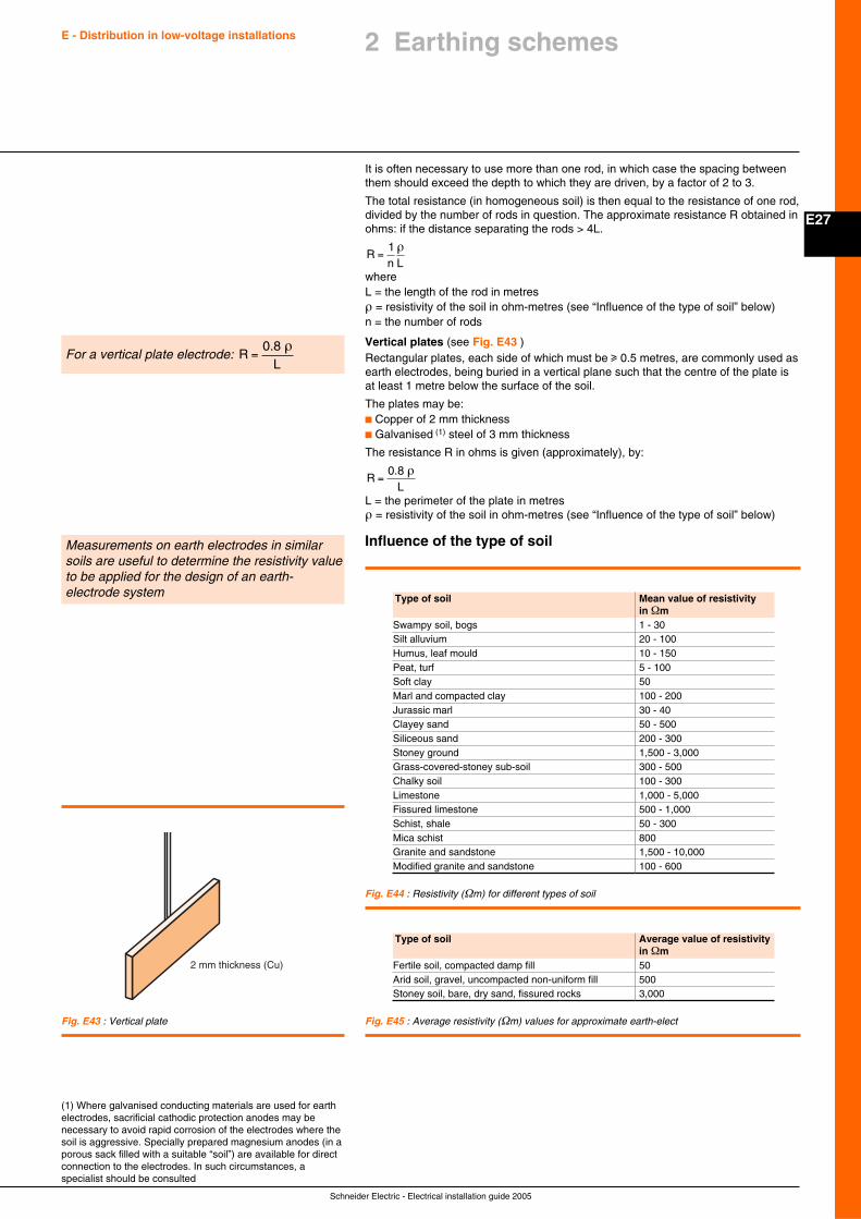
Schneider Electric - Electrical installation guide 2005
E27
E - Distribution in low-voltage installations 2 Earthing schemes
It is often necessary to use more than one rod, in which case the spacing betweenthem should exceed the depth to which they are driven, by a factor of 2 to 3.
The total resistance (in homogeneous soil) is then equal to the resistance of one rod,divided by the number of rods in question. The approximate resistance R obtained inohms: if the distance separating the rods > 4L.
Rn L
=1 ρ
whereL = the length of the rod in metresρ = resistivity of the soil in ohm-metres (see “Influence of the type of soil” below)n = the number of rods
Vertical plates (see Fig. E43 )Rectangular plates, each side of which must be u 0.5 metres, are commonly used asearth electrodes, being buried in a vertical plane such that the centre of the plate isat least 1 metre below the surface of the soil.
The plates may be:c Copper of 2 mm thicknessc Galvanised (1) steel of 3 mm thickness
The resistance R in ohms is given (approximately), by:
RL
=0.8 ρ
L = the perimeter of the plate in metresρ = resistivity of the soil in ohm-metres (see “Influence of the type of soil” below)
Influence of the type of soil
For a vertical plate electrode: RL
=0.8 ρ
(1) Where galvanised conducting materials are used for earthelectrodes, sacrificial cathodic protection anodes may benecessary to avoid rapid corrosion of the electrodes where thesoil is aggressive. Specially prepared magnesium anodes (in aporous sack filled with a suitable “soil”) are available for directconnection to the electrodes. In such circumstances, aspecialist should be consulted
Measurements on earth electrodes in similarsoils are useful to determine the resistivity valueto be applied for the design of an earth-electrode system
Fig. E43 : Vertical plate
2 mm thickness (Cu)
Fig. E44 : Resistivity (Ωm) for different types of soil
Fig. E45 : Average resistivity (Ωm) values for approximate earth-elect
Type of soil Mean value of resistivityin Ωm
Swampy soil, bogs 1 - 30Silt alluvium 20 - 100Humus, leaf mould 10 - 150Peat, turf 5 - 100Soft clay 50Marl and compacted clay 100 - 200Jurassic marl 30 - 40Clayey sand 50 - 500Siliceous sand 200 - 300Stoney ground 1,500 - 3,000Grass-covered-stoney sub-soil 300 - 500Chalky soil 100 - 300Limestone 1,000 - 5,000Fissured limestone 500 - 1,000Schist, shale 50 - 300Mica schist 800Granite and sandstone 1,500 - 10,000Modified granite and sandstone 100 - 600
Type of soil Average value of resistivityin Ωm
Fertile soil, compacted damp fill 50Arid soil, gravel, uncompacted non-uniform fill 500Stoney soil, bare, dry sand, fissured rocks 3,000
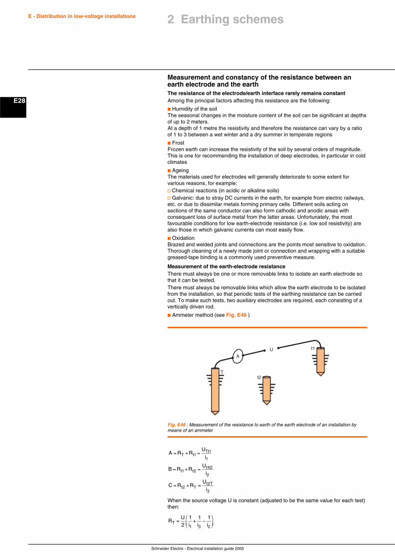
Schneider Electric - Electrical installation guide 2005
E28
E - Distribution in low-voltage installations
Measurement and constancy of the resistance between anearth electrode and the earthThe resistance of the electrode/earth interface rarely remains constantAmong the principal factors affecting this resistance are the following:
c Humidity of the soilThe seasonal changes in the moisture content of the soil can be significant at depthsof up to 2 meters.At a depth of 1 metre the resistivity and therefore the resistance can vary by a ratioof 1 to 3 between a wet winter and a dry summer in temperate regions
c FrostFrozen earth can increase the resistivity of the soil by several orders of magnitude.This is one for recommending the installation of deep electrodes, in particular in coldclimates
c AgeingThe materials used for electrodes will generally deteriorate to some extent forvarious reasons, for example:v Chemical reactions (in acidic or alkaline soils)v Galvanic: due to stray DC currents in the earth, for example from electric railways,etc. or due to dissimilar metals forming primary cells. Different soils acting onsections of the same conductor can also form cathodic and anodic areas withconsequent loss of surface metal from the latter areas. Unfortunately, the mostfavourable conditions for low earth-electrode resistance (i.e. low soil resistivity) arealso those in which galvanic currents can most easily flow.
c OxidationBrazed and welded joints and connections are the points most sensitive to oxidation.Thorough cleaning of a newly made joint or connection and wrapping with a suitablegreased-tape binding is a commonly used preventive measure.
Measurement of the earth-electrode resistanceThere must always be one or more removable links to isolate an earth electrode sothat it can be tested.There must always be removable links which allow the earth electrode to be isolatedfrom the installation, so that periodic tests of the earthing resistance can be carriedout. To make such tests, two auxiliary electrodes are required, each consisting of avertically driven rod.
c Ammeter method (see Fig. E46 )
Fig. E46 : Measurement of the resistance to earth of the earth electrode of an installation bymeans of an ammeter
UA
t2T
t1
A R RU
i
B R RU
i
C R RU
i
T tTt
t tt t
t Tt T
= + =
= + =
= + =
11
1
1 21 2
2
22
3
When the source voltage U is constant (adjusted to be the same value for each test)then:
RU
i i iT = + −⎛
⎝⎜
⎞
⎠⎟2
1 1 1
1 3 2
2 Earthing schemes
Schneider Electric - Electrical installation guide 2005
E29
E - Distribution in low-voltage installations 2 Earthing schemes
In order to avoid errors due to stray earth currents (galvanic -DC- or leakagecurrents from power and communication networks and so on) the test current shouldbe AC, but at a different frequency to that of the power system or any of itsharmonics. Instruments using hand-driven generators to make these measurementsusually produce an AC voltage at a frequency of between 85 Hz and 135 Hz.
The distances between the electrodes are not critical and may be in differentdirections from the electrode being tested, according to site conditions. A number oftests at different spacings and directions are generally made to cross-check the testresults.
c Use of a direct-reading earthing-resistance ohmmeterThese instruments use a hand-driven or electronic-type AC generator, together withtwo auxiliary electrodes, the spacing of which must be such that the zone ofinfluence of the electrode being tested should not overlap that of the test electrode (C).The test electrode (C) furthest from the electrode (X) under test, passes a currentthrough the earth and the electrode under test, while the second test electrode (P)picks up a voltage. This voltage, measured between (X) and (P), is due to the testcurrent and is a measure of the contact resistance (of the electrode under test) withearth. It is clear that the distance (X) to (P) must be carefully chosen to give accurateresults. If the distance (X) to (C) is increased, however, the zones of resistance ofelectrodes (X) and (C) become more remote, one from the other, and the curve ofpotential (voltage) becomes more nearly horizontal about the point (O).
In practical tests, therefore, the distance (X) to (C) is increased until readings takenwith electrode (P) at three different points, i.e. at (P) and at approximately 5 metreson either side of (P), give similar values. The distance (X) to (P) is generally about0.68 of the distance (X) to (C).
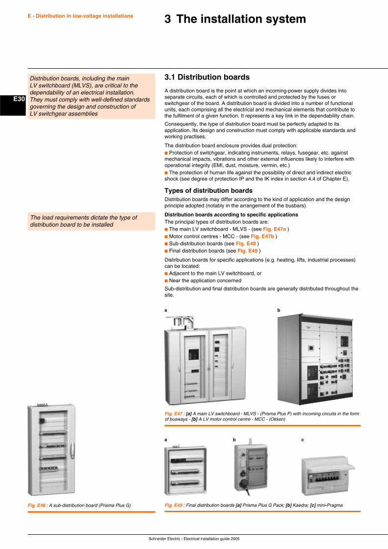
Schneider Electric - Electrical installation guide 2005
E30
E - Distribution in low-voltage installations 3 The installation system
3.1 Distribution boards
A distribution board is the point at which an incoming-power supply divides intoseparate circuits, each of which is controlled and protected by the fuses orswitchgear of the board. A distribution board is divided into a number of functionalunits, each comprising all the electrical and mechanical elements that contribute tothe fulfilment of a given function. It represents a key link in the dependability chain.
Consequently, the type of distribution board must be perfectly adapted to itsapplication. Its design and construction must comply with applicable standards andworking practises.
The distribution board enclosure provides dual protection:c Protection of switchgear, indicating instruments, relays, fusegear, etc. againstmechanical impacts, vibrations and other external influences likely to interfere withoperational integrity (EMI, dust, moisture, vermin, etc.)c The protection of human life against the possibility of direct and indirect electricshock (see degree of protection IP and the IK index in section 4.4 of Chapter E).
Types of distribution boardsDistribution boards may differ according to the kind of application and the designprinciple adopted (notably in the arrangement of the busbars).
Distribution boards according to specific applicationsThe principal types of distribution boards are:c The main LV switchboard - MLVS - (see Fig. E47a )c Motor control centres - MCC - (see Fig. E47b )c Sub-distribution boards (see Fig. E48 )c Final distribution boards (see Fig. E49 )
Distribution boards for specific applications (e.g. heating, lifts, industrial processes)can be located:c Adjacent to the main LV switchboard, orc Near the application concerned
Sub-distribution and final distribution boards are generally distributed throughout thesite.
Distribution boards, including the mainLV switchboard (MLVS), are critical to thedependability of an electrical installation.They must comply with well-defined standardsgoverning the design and construction ofLV switchgear assemblies
The load requirements dictate the type ofdistribution board to be installed
Fig. E47 : [a] A main LV switchboard - MLVS - (Prisma Plus P) with incoming circuits in the formof busways - [b] A LV motor control centre - MCC - (Okken)
Fig. E48 : A sub-distribution board (Prisma Plus G) Fig. E49 : Final distribution boards [a] Prisma Plus G Pack; [b] Kaedra; [c] mini-Pragma
a b c
a b
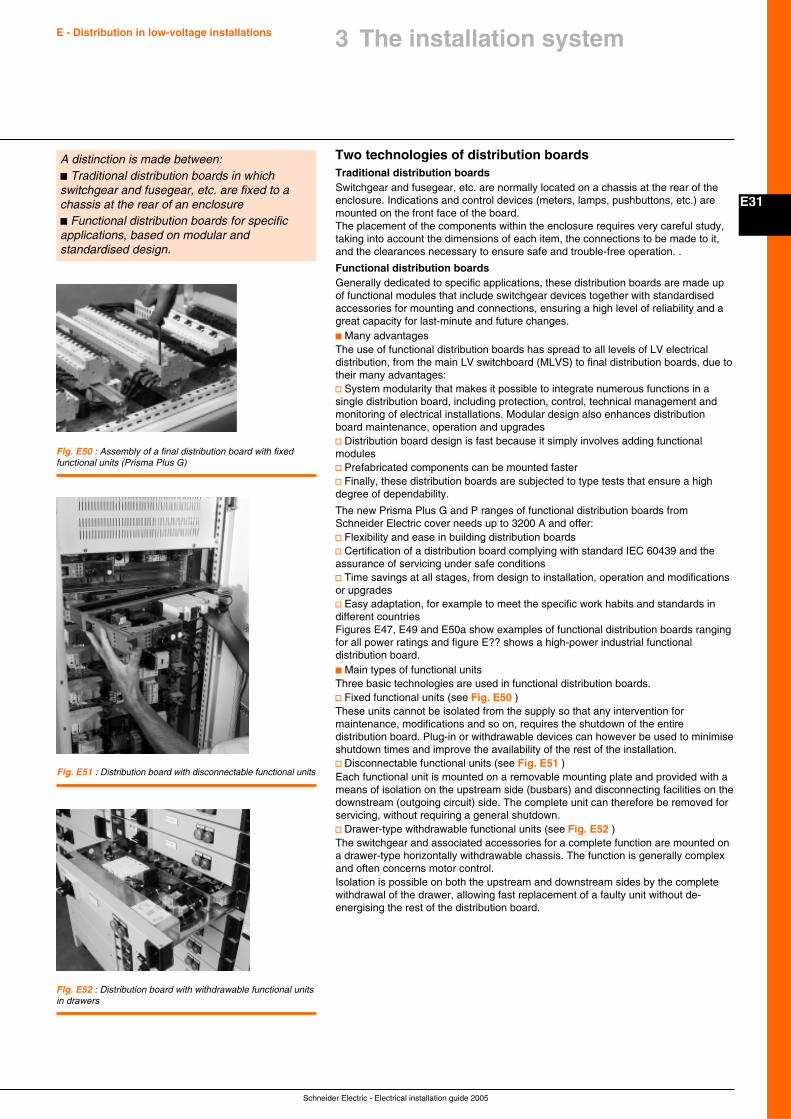
Schneider Electric - Electrical installation guide 2005
E31
E - Distribution in low-voltage installations 3 The installation system
Two technologies of distribution boardsTraditional distribution boardsSwitchgear and fusegear, etc. are normally located on a chassis at the rear of theenclosure. Indications and control devices (meters, lamps, pushbuttons, etc.) aremounted on the front face of the board.The placement of the components within the enclosure requires very careful study,taking into account the dimensions of each item, the connections to be made to it,and the clearances necessary to ensure safe and trouble-free operation. .
Functional distribution boardsGenerally dedicated to specific applications, these distribution boards are made upof functional modules that include switchgear devices together with standardisedaccessories for mounting and connections, ensuring a high level of reliability and agreat capacity for last-minute and future changes.c Many advantagesThe use of functional distribution boards has spread to all levels of LV electricaldistribution, from the main LV switchboard (MLVS) to final distribution boards, due totheir many advantages:v System modularity that makes it possible to integrate numerous functions in asingle distribution board, including protection, control, technical management andmonitoring of electrical installations. Modular design also enhances distributionboard maintenance, operation and upgradesv Distribution board design is fast because it simply involves adding functionalmodulesv Prefabricated components can be mounted fasterv Finally, these distribution boards are subjected to type tests that ensure a highdegree of dependability.
The new Prisma Plus G and P ranges of functional distribution boards fromSchneider Electric cover needs up to 3200 A and offer:v Flexibility and ease in building distribution boardsv Certification of a distribution board complying with standard IEC 60439 and theassurance of servicing under safe conditionsv Time savings at all stages, from design to installation, operation and modificationsor upgradesv Easy adaptation, for example to meet the specific work habits and standards indifferent countriesFigures E47, E49 and E50a show examples of functional distribution boards rangingfor all power ratings and figure E?? shows a high-power industrial functionaldistribution board.c Main types of functional unitsThree basic technologies are used in functional distribution boards.v Fixed functional units (see Fig. E50 )These units cannot be isolated from the supply so that any intervention formaintenance, modifications and so on, requires the shutdown of the entiredistribution board. Plug-in or withdrawable devices can however be used to minimiseshutdown times and improve the availability of the rest of the installation.v Disconnectable functional units (see Fig. E51 )Each functional unit is mounted on a removable mounting plate and provided with ameans of isolation on the upstream side (busbars) and disconnecting facilities on thedownstream (outgoing circuit) side. The complete unit can therefore be removed forservicing, without requiring a general shutdown.v Drawer-type withdrawable functional units (see Fig. E52 )The switchgear and associated accessories for a complete function are mounted ona drawer-type horizontally withdrawable chassis. The function is generally complexand often concerns motor control.Isolation is possible on both the upstream and downstream sides by the completewithdrawal of the drawer, allowing fast replacement of a faulty unit without de-energising the rest of the distribution board.
A distinction is made between:c Traditional distribution boards in whichswitchgear and fusegear, etc. are fixed to achassis at the rear of an enclosurec Functional distribution boards for specificapplications, based on modular andstandardised design.
Fig. E50 : Assembly of a final distribution board with fixedfunctional units (Prisma Plus G)
Fig. E51 : Distribution board with disconnectable functional units
Fig. E52 : Distribution board with withdrawable functional unitsin drawers
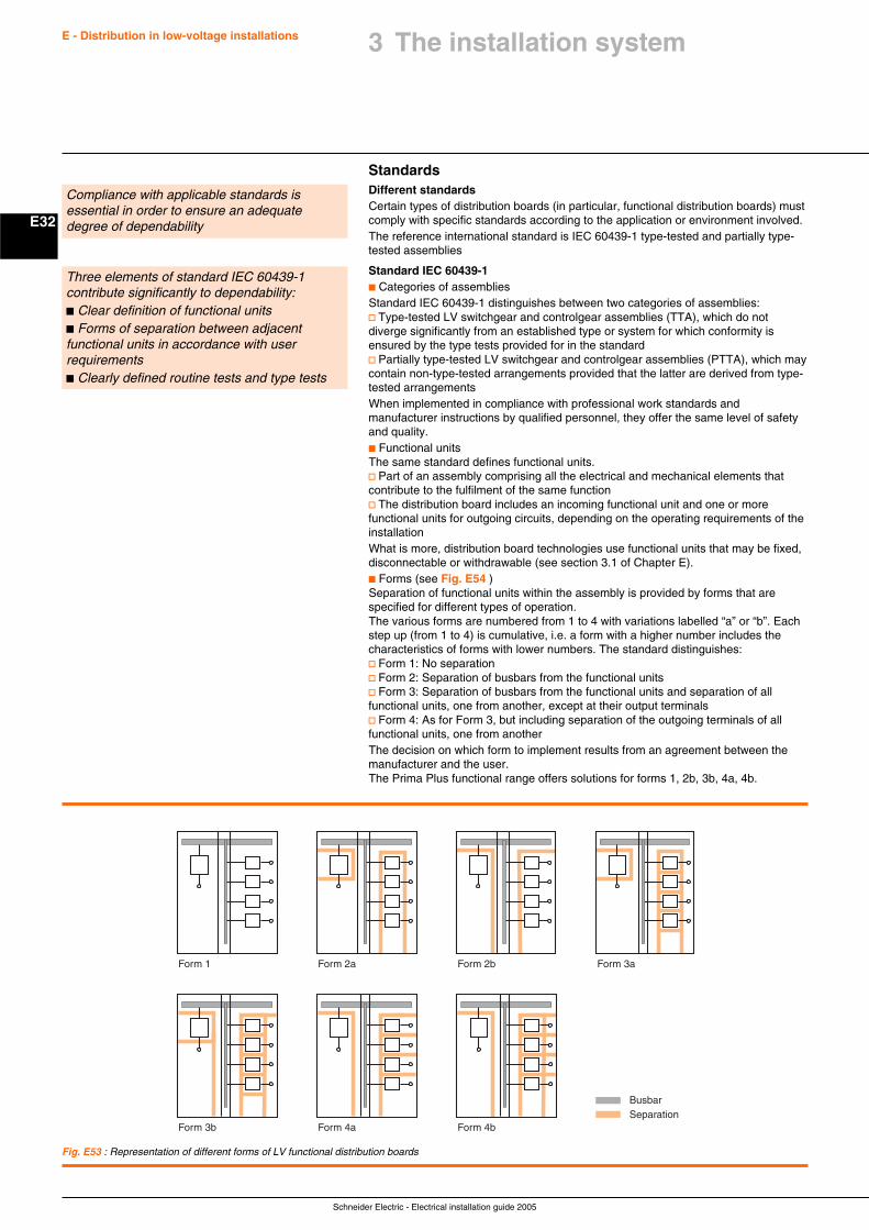
Schneider Electric - Electrical installation guide 2005
E32
E - Distribution in low-voltage installations
StandardsDifferent standardsCertain types of distribution boards (in particular, functional distribution boards) mustcomply with specific standards according to the application or environment involved.The reference international standard is IEC 60439-1 type-tested and partially type-tested assemblies
Standard IEC 60439-1c Categories of assembliesStandard IEC 60439-1 distinguishes between two categories of assemblies:v Type-tested LV switchgear and controlgear assemblies (TTA), which do notdiverge significantly from an established type or system for which conformity isensured by the type tests provided for in the standardv Partially type-tested LV switchgear and controlgear assemblies (PTTA), which maycontain non-type-tested arrangements provided that the latter are derived from type-tested arrangementsWhen implemented in compliance with professional work standards andmanufacturer instructions by qualified personnel, they offer the same level of safetyand quality.c Functional unitsThe same standard defines functional units.v Part of an assembly comprising all the electrical and mechanical elements thatcontribute to the fulfilment of the same functionv The distribution board includes an incoming functional unit and one or morefunctional units for outgoing circuits, depending on the operating requirements of theinstallationWhat is more, distribution board technologies use functional units that may be fixed,disconnectable or withdrawable (see section 3.1 of Chapter E).c Forms (see Fig. E54 )Separation of functional units within the assembly is provided by forms that arespecified for different types of operation.The various forms are numbered from 1 to 4 with variations labelled “a” or “b”. Eachstep up (from 1 to 4) is cumulative, i.e. a form with a higher number includes thecharacteristics of forms with lower numbers. The standard distinguishes:v Form 1: No separationv Form 2: Separation of busbars from the functional unitsv Form 3: Separation of busbars from the functional units and separation of allfunctional units, one from another, except at their output terminalsv Form 4: As for Form 3, but including separation of the outgoing terminals of allfunctional units, one from anotherThe decision on which form to implement results from an agreement between themanufacturer and the user.The Prima Plus functional range offers solutions for forms 1, 2b, 3b, 4a, 4b.
Compliance with applicable standards isessential in order to ensure an adequatedegree of dependability
Three elements of standard IEC 60439-1contribute significantly to dependability:c Clear definition of functional unitsc Forms of separation between adjacentfunctional units in accordance with userrequirementsc Clearly defined routine tests and type tests
Fig. E53 : Representation of different forms of LV functional distribution boards
Form 1 Form 2a Form 2b Form 3a
BusbarSeparation
Form 3b Form 4a Form 4b
3 The installation system
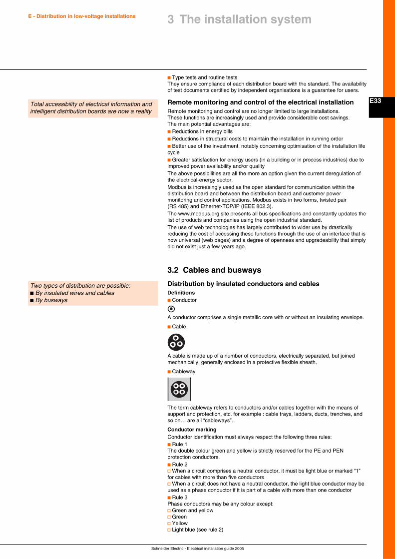
Schneider Electric - Electrical installation guide 2005
E33
E - Distribution in low-voltage installations 3 The installation system
c Type tests and routine testsThey ensure compliance of each distribution board with the standard. The availabilityof test documents certified by independent organisations is a guarantee for users.
Remote monitoring and control of the electrical installationRemote monitoring and control are no longer limited to large installations.These functions are increasingly used and provide considerable cost savings.The main potential advantages are:c Reductions in energy billsc Reductions in structural costs to maintain the installation in running orderc Better use of the investment, notably concerning optimisation of the installation lifecyclec Greater satisfaction for energy users (in a building or in process industries) due toimproved power availability and/or qualityThe above possibilities are all the more an option given the current deregulation ofthe electrical-energy sector.Modbus is increasingly used as the open standard for communication within thedistribution board and between the distribution board and customer powermonitoring and control applications. Modbus exists in two forms, twisted pair(RS 485) and Ethernet-TCP/IP (IEEE 802.3).The www.modbus.org site presents all bus specifications and constantly updates thelist of products and companies using the open industrial standard.The use of web technologies has largely contributed to wider use by drasticallyreducing the cost of accessing these functions through the use of an interface that isnow universal (web pages) and a degree of openness and upgradeability that simplydid not exist just a few years ago.
3.2 Cables and busways
Distribution by insulated conductors and cablesDefinitionsc Conductor
A conductor comprises a single metallic core with or without an insulating envelope.
c Cable
A cable is made up of a number of conductors, electrically separated, but joinedmechanically, generally enclosed in a protective flexible sheath.
c Cableway
The term cableway refers to conductors and/or cables together with the means ofsupport and protection, etc. for example : cable trays, ladders, ducts, trenches, andso on… are all “cableways”.
Conductor markingConductor identification must always respect the following three rules:c Rule 1The double colour green and yellow is strictly reserved for the PE and PENprotection conductors.c Rule 2v When a circuit comprises a neutral conductor, it must be light blue or marked “1”for cables with more than five conductorsv When a circuit does not have a neutral conductor, the light blue conductor may beused as a phase conductor if it is part of a cable with more than one conductorc Rule 3Phase conductors may be any colour except:v Green and yellowv Greenv Yellowv Light blue (see rule 2)
Total accessibility of electrical information andintelligent distribution boards are now a reality
Two types of distribution are possible:c By insulated wires and cablesc By busways
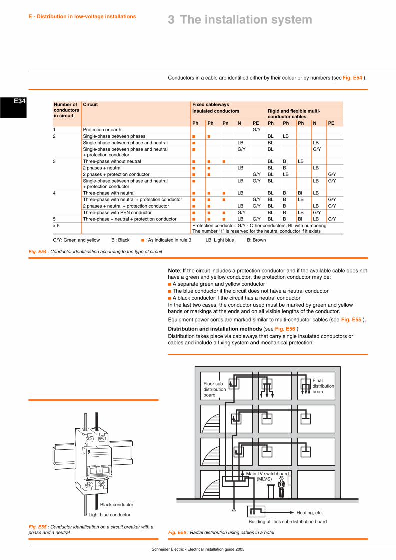
Schneider Electric - Electrical installation guide 2005
E34
E - Distribution in low-voltage installations
Conductors in a cable are identified either by their colour or by numbers (see Fig. E54 ).
Number of Circuit Fixed cablewaysconductors Insulated conductors Rigid and flexible multi-in circuit conductor cables
Ph Ph Pn N PE Ph Ph Ph N PE1 Protection or earth G/Y2 Single-phase between phases c c BL LB
Single-phase between phase and neutral c LB BL LBSingle-phase between phase and neutral c G/Y BL G/Y+ protection conductor
3 Three-phase without neutral c c c BL B LB2 phases + neutral c c LB BL B LB2 phases + protection conductor c c G/Y BL LB G/YSingle-phase between phase and neutral c LB G/Y BL LB G/Y+ protection conductor
4 Three-phase with neutral c c c LB BL B Bl LBThree-phase with neutral + protection conductor c c c G/Y BL B LB G/Y2 phases + neutral + protection conductor c c LB G/Y BL B LB G/YThree-phase with PEN conductor c c c G/Y BL B LB G/Y
5 Three-phase + neutral + protection conductor c c c LB G/Y BL B Bl LB G/Y> 5 Protection conductor: G/Y - Other conductors: Bl: with numbering
The number “1” is reserved for the neutral conductor if it exists
G/Y: Green and yellow Bl: Black c : As indicated in rule 3 LB: Light blue B: Brown
Note: If the circuit includes a protection conductor and if the available cable does nothave a green and yellow conductor, the protection conductor may be:c A separate green and yellow conductorc The blue conductor if the circuit does not have a neutral conductorc A black conductor if the circuit has a neutral conductorIn the last two cases, the conductor used must be marked by green and yellowbands or markings at the ends and on all visible lengths of the conductor.
Equipment power cords are marked similar to multi-conductor cables (see Fig. E55 ).
Distribution and installation methods (see Fig. E56 )Distribution takes place via cableways that carry single insulated conductors orcables and include a fixing system and mechanical protection.
Fig. E54 : Conductor identification according to the type of circuit
Fig. E55 : Conductor identification on a circuit breaker with aphase and a neutral
Black conductor
N
Light blue conductor Heating, etc.
Building utilities sub-distribution board
Main LV switchboard(MLVS)
Finaldistributionboard
Floor sub-distributionboard
Fig. E56 : Radial distribution using cables in a hotel
3 The installation system
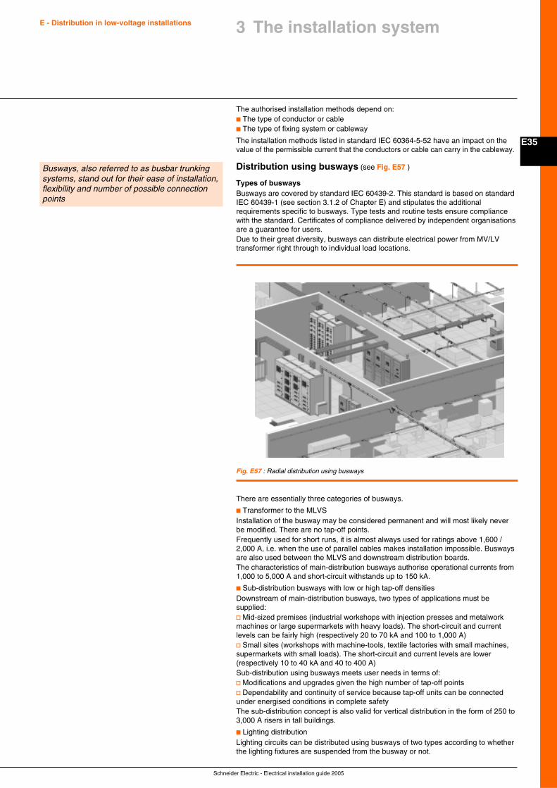
Schneider Electric - Electrical installation guide 2005
E35
E - Distribution in low-voltage installations 3 The installation system
The authorised installation methods depend on:c The type of conductor or cablec The type of fixing system or cableway
The installation methods listed in standard IEC 60364-5-52 have an impact on thevalue of the permissible current that the conductors or cable can carry in the cableway.
Distribution using busways (see Fig. E57 )
Types of buswaysBusways are covered by standard IEC 60439-2. This standard is based on standardIEC 60439-1 (see section 3.1.2 of Chapter E) and stipulates the additionalrequirements specific to busways. Type tests and routine tests ensure compliancewith the standard. Certificates of compliance delivered by independent organisationsare a guarantee for users.Due to their great diversity, busways can distribute electrical power from MV/LVtransformer right through to individual load locations.
Busways, also referred to as busbar trunkingsystems, stand out for their ease of installation,flexibility and number of possible connectionpoints
Fig. E57 : Radial distribution using busways
There are essentially three categories of busways.
c Transformer to the MLVSInstallation of the busway may be considered permanent and will most likely neverbe modified. There are no tap-off points.Frequently used for short runs, it is almost always used for ratings above 1,600 /2,000 A, i.e. when the use of parallel cables makes installation impossible. Buswaysare also used between the MLVS and downstream distribution boards.The characteristics of main-distribution busways authorise operational currents from1,000 to 5,000 A and short-circuit withstands up to 150 kA.
c Sub-distribution busways with low or high tap-off densitiesDownstream of main-distribution busways, two types of applications must besupplied:v Mid-sized premises (industrial workshops with injection presses and metalworkmachines or large supermarkets with heavy loads). The short-circuit and currentlevels can be fairly high (respectively 20 to 70 kA and 100 to 1,000 A)v Small sites (workshops with machine-tools, textile factories with small machines,supermarkets with small loads). The short-circuit and current levels are lower(respectively 10 to 40 kA and 40 to 400 A)Sub-distribution using busways meets user needs in terms of:v Modifications and upgrades given the high number of tap-off pointsv Dependability and continuity of service because tap-off units can be connectedunder energised conditions in complete safetyThe sub-distribution concept is also valid for vertical distribution in the form of 250 to3,000 A risers in tall buildings.
c Lighting distributionLighting circuits can be distributed using busways of two types according to whetherthe lighting fixtures are suspended from the busway or not.
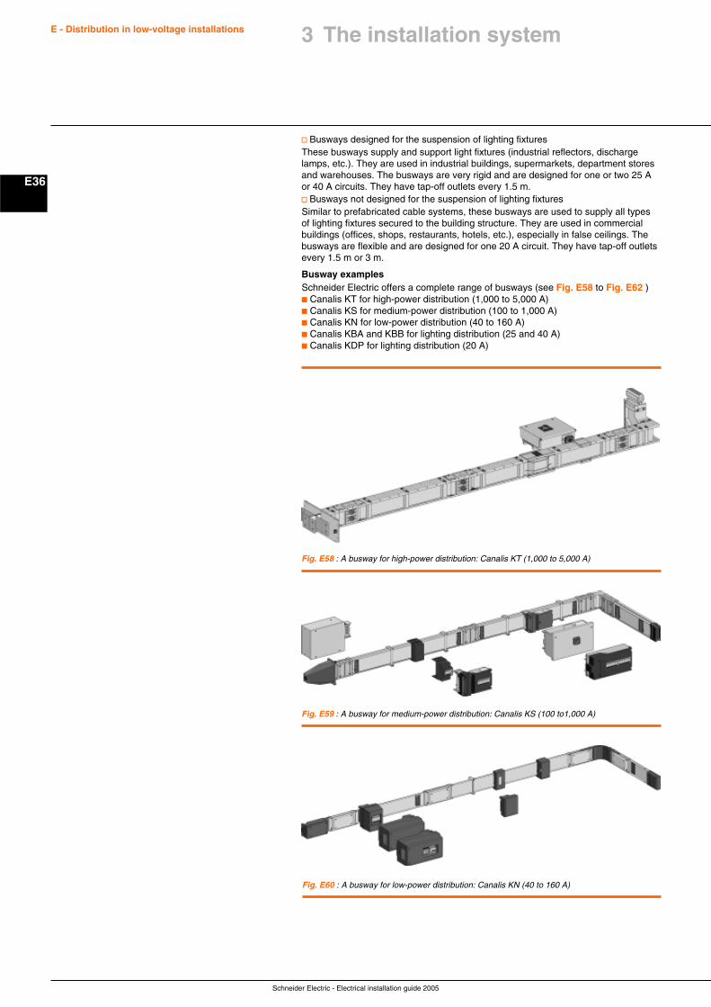
Schneider Electric - Electrical installation guide 2005
E36
E - Distribution in low-voltage installations
v Busways designed for the suspension of lighting fixturesThese busways supply and support light fixtures (industrial reflectors, dischargelamps, etc.). They are used in industrial buildings, supermarkets, department storesand warehouses. The busways are very rigid and are designed for one or two 25 Aor 40 A circuits. They have tap-off outlets every 1.5 m.v Busways not designed for the suspension of lighting fixturesSimilar to prefabricated cable systems, these busways are used to supply all typesof lighting fixtures secured to the building structure. They are used in commercialbuildings (offices, shops, restaurants, hotels, etc.), especially in false ceilings. Thebusways are flexible and are designed for one 20 A circuit. They have tap-off outletsevery 1.5 m or 3 m.
Busway examplesSchneider Electric offers a complete range of busways (see Fig. E58 to Fig. E62 )c Canalis KT for high-power distribution (1,000 to 5,000 A)c Canalis KS for medium-power distribution (100 to 1,000 A)c Canalis KN for low-power distribution (40 to 160 A)c Canalis KBA and KBB for lighting distribution (25 and 40 A)c Canalis KDP for lighting distribution (20 A)
Fig. E58 : A busway for high-power distribution: Canalis KT (1,000 to 5,000 A)
Fig. E59 : A busway for medium-power distribution: Canalis KS (100 to1,000 A)
Fig. E60 : A busway for low-power distribution: Canalis KN (40 to 160 A)
3 The installation system
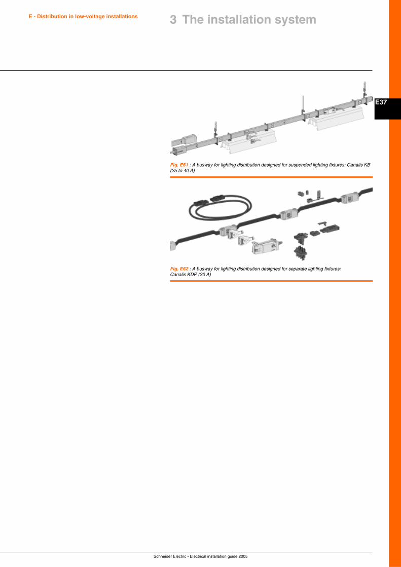
Schneider Electric - Electrical installation guide 2005
E37
E - Distribution in low-voltage installations 3 The installation system
Fig. E61 : A busway for lighting distribution designed for suspended lighting fixtures: Canalis KB(25 to 40 A)
Fig. E62 : A busway for lighting distribution designed for separate lighting fixtures:Canalis KDP (20 A)
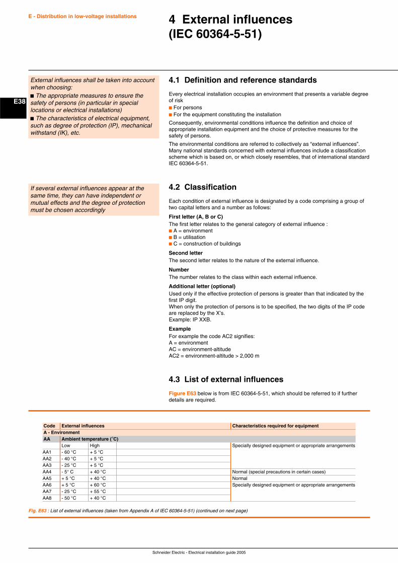
Schneider Electric - Electrical installation guide 2005
E38
E - Distribution in low-voltage installations 4 External influences(IEC 60364-5-51)
4.1 Definition and reference standards
Every electrical installation occupies an environment that presents a variable degreeof riskc For personsc For the equipment constituting the installation
Consequently, environmental conditions influence the definition and choice ofappropriate installation equipment and the choice of protective measures for thesafety of persons.
The environmental conditions are referred to collectively as “external influences”.Many national standards concerned with external influences include a classificationscheme which is based on, or which closely resembles, that of international standardIEC 60364-5-51.
4.2 Classification
Each condition of external influence is designated by a code comprising a group oftwo capital letters and a number as follows:
First letter (A, B or C)The first letter relates to the general category of external influence :c A = environmentc B = utilisationc C = construction of buildings
Second letterThe second letter relates to the nature of the external influence.
NumberThe number relates to the class within each external influence.
Additional letter (optional)Used only if the effective protection of persons is greater than that indicated by thefirst IP digit.When only the protection of persons is to be specified, the two digits of the IP codeare replaced by the X’s.Example: IP XXB.
ExampleFor example the code AC2 signifies:A = environmentAC = environment-altitudeAC2 = environment-altitude > 2,000 m
4.3 List of external influences
Figure E63 below is from IEC 60364-5-51, which should be referred to if furtherdetails are required.
External influences shall be taken into accountwhen choosing:c The appropriate measures to ensure thesafety of persons (in particular in speciallocations or electrical installations)c The characteristics of electrical equipment,such as degree of protection (IP), mechanicalwithstand (IK), etc.
If several external influences appear at thesame time, they can have independent ormutual effects and the degree of protectionmust be chosen accordingly
Code External influences Characteristics required for equipmentA - EnvironmentAA Ambient temperature (°C)
Low High Specially designed equipment or appropriate arrangementsAA1 - 60 °C + 5 °CAA2 - 40 °C + 5 °CAA3 - 25 °C + 5 °CAA4 - 5° C + 40 °C Normal (special precautions in certain cases)AA5 + 5 °C + 40 °C NormalAA6 + 5 °C + 60 °C Specially designed equipment or appropriate arrangementsAA7 - 25 °C + 55 °CAA8 - 50 °C + 40 °C
Fig. E63 : List of external influences (taken from Appendix A of IEC 60364-5-51) (continued on next page)
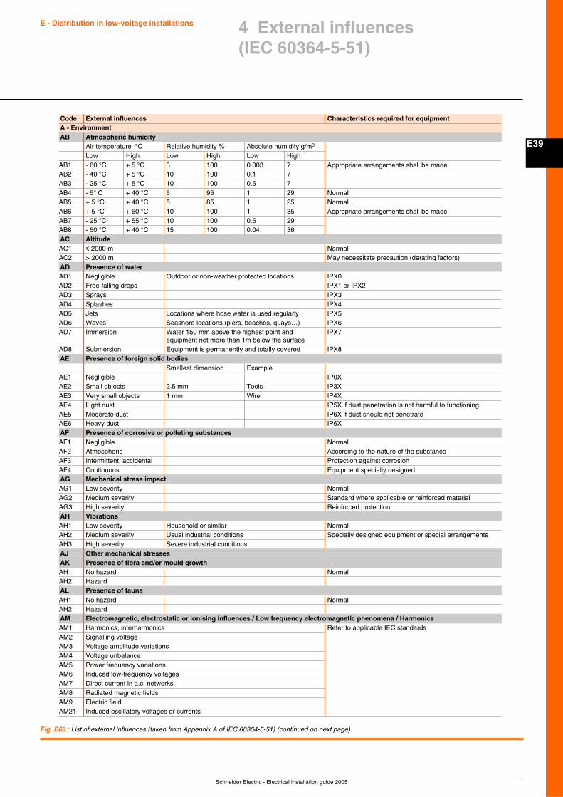
Schneider Electric - Electrical installation guide 2005
E39
E - Distribution in low-voltage installations 4 External influences(IEC 60364-5-51)
Code External influences Characteristics required for equipmentA - EnvironmentAB Atmospheric humidity
Air temperature °C Relative humidity % Absolute humidity g/m3
Low High Low High Low HighAB1 - 60 °C + 5 °C 3 100 0.003 7 Appropriate arrangements shall be madeAB2 - 40 °C + 5 °C 10 100 0.1 7AB3 - 25 °C + 5 °C 10 100 0.5 7AB4 - 5° C + 40 °C 5 95 1 29 NormalAB5 + 5 °C + 40 °C 5 85 1 25 NormalAB6 + 5 °C + 60 °C 10 100 1 35 Appropriate arrangements shall be madeAB7 - 25 °C + 55 °C 10 100 0.5 29AB8 - 50 °C + 40 °C 15 100 0.04 36AC AltitudeAC1 i 2000 m NormalAC2 > 2000 m May necessitate precaution (derating factors)AD Presence of waterAD1 Negligible Outdoor or non-weather protected locations IPX0AD2 Free-falling drops IPX1 or IPX2AD3 Sprays IPX3AD4 Splashes IPX4AD5 Jets Locations where hose water is used regularly IPX5AD6 Waves Seashore locations (piers, beaches, quays…) IPX6AD7 Immersion Water 150 mm above the highest point and IPX7
equipment not more than 1m below the surfaceAD8 Submersion Equipment is permanently and totally covered IPX8AE Presence of foreign solid bodies
Smallest dimension ExampleAE1 Negligible IP0XAE2 Small objects 2.5 mm Tools IP3XAE3 Very small objects 1 mm Wire IP4XAE4 Light dust IP5X if dust penetration is not harmful to functioningAE5 Moderate dust IP6X if dust should not penetrateAE6 Heavy dust IP6XAF Presence of corrosive or polluting substancesAF1 Negligible NormalAF2 Atmospheric According to the nature of the substanceAF3 Intermittent, accidental Protection against corrosionAF4 Continuous Equipment specially designedAG Mechanical stress impactAG1 Low severity NormalAG2 Medium severity Standard where applicable or reinforced materialAG3 High severity Reinforced protectionAH VibrationsAH1 Low severity Household or similar NormalAH2 Medium severity Usual industrial conditions Specially designed equipment or special arrangementsAH3 High severity Severe industrial conditionsAJ Other mechanical stressesAK Presence of flora and/or mould growthAH1 No hazard NormalAH2 HazardAL Presence of faunaAH1 No hazard NormalAH2 HazardAM Electromagnetic, electrostatic or ionising influences / Low frequency electromagnetic phenomena / HarmonicsAM1 Harmonics, interharmonics Refer to applicable IEC standardsAM2 Signalling voltageAM3 Voltage amplitude variationsAM4 Voltage unbalanceAM5 Power frequency variationsAM6 Induced low-frequency voltagesAM7 Direct current in a.c. networksAM8 Radiated magnetic fieldsAM9 Electric fieldAM21 Induced oscillatory voltages or currents
Fig. E63 : List of external influences (taken from Appendix A of IEC 60364-5-51) (continued on next page)
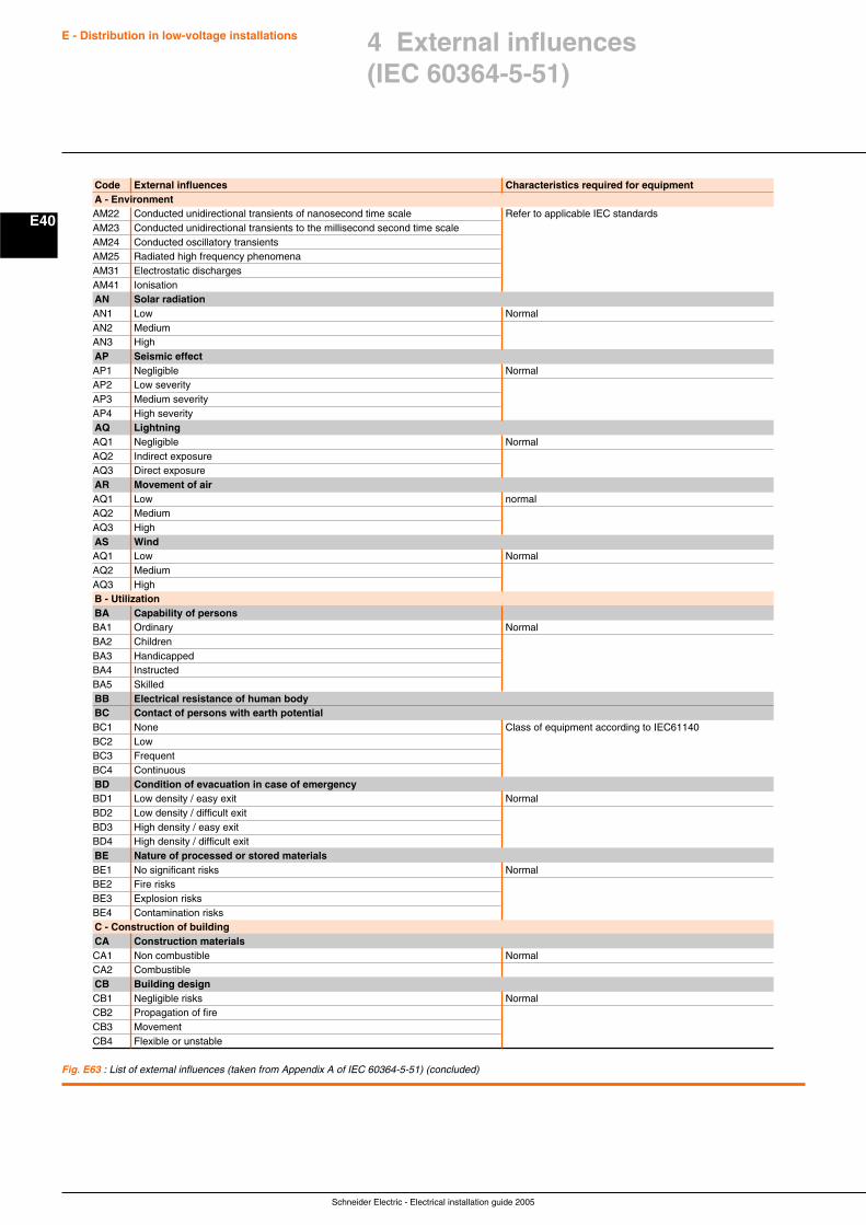
Schneider Electric - Electrical installation guide 2005
E40
E - Distribution in low-voltage installations
Fig. E63 : List of external influences (taken from Appendix A of IEC 60364-5-51) (concluded)
Code External influences Characteristics required for equipmentA - EnvironmentAM22 Conducted unidirectional transients of nanosecond time scale Refer to applicable IEC standardsAM23 Conducted unidirectional transients to the millisecond second time scaleAM24 Conducted oscillatory transientsAM25 Radiated high frequency phenomenaAM31 Electrostatic dischargesAM41 IonisationAN Solar radiationAN1 Low NormalAN2 MediumAN3 HighAP Seismic effectAP1 Negligible NormalAP2 Low severityAP3 Medium severityAP4 High severityAQ LightningAQ1 Negligible NormalAQ2 Indirect exposureAQ3 Direct exposureAR Movement of airAQ1 Low normalAQ2 MediumAQ3 HighAS WindAQ1 Low NormalAQ2 MediumAQ3 HighB - UtilizationBA Capability of personsBA1 Ordinary NormalBA2 ChildrenBA3 HandicappedBA4 InstructedBA5 SkilledBB Electrical resistance of human bodyBC Contact of persons with earth potentialBC1 None Class of equipment according to IEC61140BC2 LowBC3 FrequentBC4 ContinuousBD Condition of evacuation in case of emergencyBD1 Low density / easy exit NormalBD2 Low density / difficult exitBD3 High density / easy exitBD4 High density / difficult exitBE Nature of processed or stored materialsBE1 No significant risks NormalBE2 Fire risksBE3 Explosion risksBE4 Contamination risksC - Construction of buildingCA Construction materialsCA1 Non combustible NormalCA2 CombustibleCB Building designCB1 Negligible risks NormalCB2 Propagation of fireCB3 MovementCB4 Flexible or unstable
4 External influences(IEC 60364-5-51)
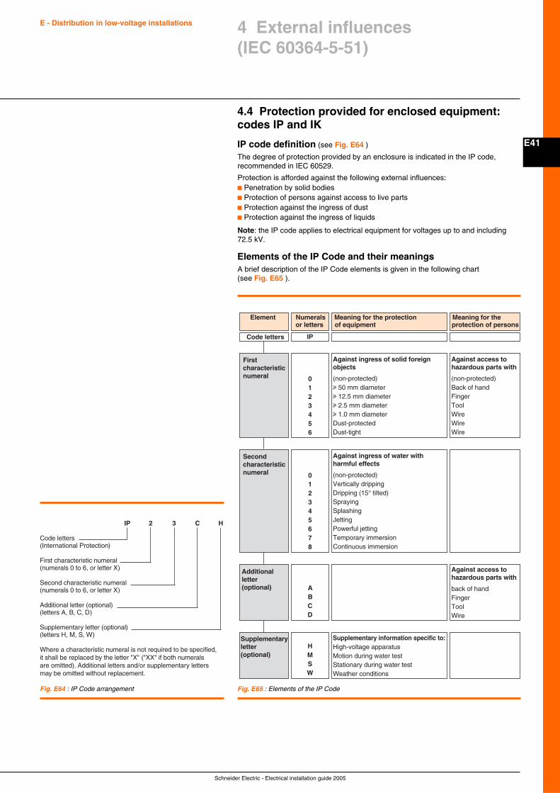
Schneider Electric - Electrical installation guide 2005
E41
E - Distribution in low-voltage installations
4.4 Protection provided for enclosed equipment:codes IP and IK
IP code definition (see Fig. E64 )
The degree of protection provided by an enclosure is indicated in the IP code,recommended in IEC 60529.
Protection is afforded against the following external influences:c Penetration by solid bodiesc Protection of persons against access to live partsc Protection against the ingress of dustc Protection against the ingress of liquids
Note: the IP code applies to electrical equipment for voltages up to and including72.5 kV.
Elements of the IP Code and their meaningsA brief description of the IP Code elements is given in the following chart(see Fig. E65 ).
4 External influences(IEC 60364-5-51)
Fig. E64 : IP Code arrangement
IP 2 3 C H
Code letters(International Protection)
First characteristic numeral(numerals 0 to 6, or letter X)
Second characteristic numeral(numerals 0 to 6, or letter X)
Additional letter (optional)(letters A, B, C, D)
Supplementary letter (optional)(letters H, M, S, W)
Where a characteristic numeral is not required to be specified, it shall be replaced by the letter "X" ("XX" if both numerals are omitted). Additional letters and/or supplementary letters may be omitted without replacement.
Code letters
Element Numeralsor letters
Meaning for the protection of equipment
Meaning for theprotection of persons
Firstcharacteristicnumeral 0
123456
IP
Against ingress of solid foreign objects
(non-protected)u 50 mm diameteru 12.5 mm diameteru 2.5 mm diameteru 1.0 mm diameterDust-protectedDust-tight
Against access tohazardous parts with
(non-protected)Back of hand FingerToolWireWireWire
Additional letter(optional) A
BCD
Against access tohazardous parts with
back of hand FingerToolWire
Supplementaryletter (optional)
HMSW
Supplementary information specific to:High-voltage apparatusMotion during water testStationary during water testWeather conditions
Secondcharacteristicnumeral 0
12345678
Against ingress of water with harmful effects
(non-protected)Vertically drippingDripping (15° tilted)SprayingSplashingJettingPowerful jettingTemporary immersionContinuous immersion
Fig. E65 : Elements of the IP Code
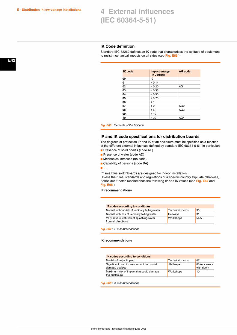
Schneider Electric - Electrical installation guide 2005
E - Distribution in low-voltage installations
E42
4 External influences(IEC 60364-5-51)
IK Code definitionStandard IEC 62262 defines an IK code that characterises the aptitude of equipmentto resist mechanical impacts on all sides (see Fig. E66 ).
Fig. E66 : Elements of the IK Code
IK code Impact energy AG code(in Joules)
00 001 i 0.1402 i 0.20 AG103 i 0.3504 i 0.5005 i 0.7006 i 107 i 2 AG208 i 5 AG309 i 1010 i 20 AG4
IP and IK code specifications for distribution boardsThe degrees of protection IP and IK of an enclosure must be specified as a functionof the different external influences defined by standard IEC 60364-5-51, in particular:c Presence of solid bodies (code AE)c Presence of water (code AD)c Mechanical stresses (no code)c Capability of persons (code BA)c …
Prisma Plus switchboards are designed for indoor installation.Unless the rules, standards and regulations of a specific country stipulate otherwise,Schneider Electric recommends the following IP and IK values (see Fig. E67 andFig. E68 )
IP recommendations
Fig. E67 : IP recommendations
Fig. E68 : IK recommendations
IK recommendations
IP codes according to conditionsNormal without risk of vertically falling water Technical rooms 30Normal with risk of vertically falling water Hallways 31Very severe with risk of splashing water Workshops 54/55from all directions
IK codes according to conditionsNo risk of major impact Technical rooms 07Significant risk of major impact that could Hallways 08 (enclosuredamage devices with door)Maximum risk of impact that could damage Workshops 10the enclosure
F1
Schneider Electric - Electrical installation guide 2005
Chapter FProtection against electric shocks
Contents
General F2
1.1 Electric shock F2
1.2 Protection against electric shock F3
1.3 Direct and indirect contact F3
Protection against direct contact F4
2.1 Measures of protection against direct contact F4
2.2 Additional measure of protection against direct contact F5
Protection against indirect contact F6
3.1 Measures of protection by automaticdisconnection of the supply F6
3.2 Automatic disconnection for TT system F7
3.3 Automatic disconnection for TN systems F8
3.4 Automatic disconnection on a second fault in an IT system F10
3.5 Measures of protection against direct or indirect contactwithout automatic disconnection of supply F13
Protection of goods due to insulation fault F17
4.1 Measures of protection against fire risk with RCDs F17
4.2 Ground Fault Protection (GFP) F17
Implementation of the TT system F19
5.1 Protective measures F19
5.2 Types of RCD F20
5.3 Coordination of residual current protective devices F22
Implementation of the TN system F25
6.1 Preliminary conditions F25
6.2 Protection against indirect contact F25
6.3 High-sensitivity RCDs F29
6.4 Protection in high fire-risk locations F30
6.5 When the fault current-loop impedance is particularly high F30
Implementation of the IT system F31
7.1 Preliminary conditions F31
7.2 Protection against indirect contact F32
7.3 High-sensitivity RCDs F36
7.4 In areas high fire-risk F37
7.5 When the fault current-loop impedance is particularly high F37
Residual current differential devices (RCDs) F38
8.1 Description F38
8.2 Recommendations for RCDs implementation F38
1
2
3
4
5
6
7
8
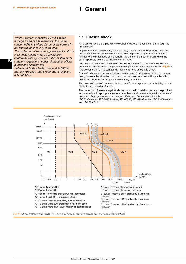
Schneider Electric - Electrical installation guide 2005
F2
F - Protection against electric shock 1 General
1.1 Electric shock
An electric shock is the pathophysiological effect of an electric current through thehuman body.
Its passage affects essentially the muscular, circulatory and respiratory functionsand sometimes results in serious burns. The degree of danger for the victim is afunction of the magnitude of the current, the parts of the body through which thecurrent passes, and the duration of current flow.
IEC publication 60479-1dated 1994 defines four zones of current-magnitude/time-duration, in each of which the pathophysiological effects are described (see Fig F1 ).Any person coming into contact with live metal risks an electric shock.
Curve C1 shows that when a current greater than 30 mA passes through a humanbeing from one hand to the other hand, the person concerned is likely to be killed,unless the current is interrupted in a relatively short time.
The point 500 ms/100 mA close to the curve C1 corresponds to a probability of heartfibrillation of the order of 0.14%.
The protection of persons against electric shock in LV installations must be providedin conformity with appropriate national standards and statutory regulations, codes ofpractice, official guides and circulars, etc. Relevant IEC standards include:IEC 60364 series, IEC 60479 series, IEC 60755, IEC 61008 series, IEC 61009 seriesand IEC 60947-2.
Fig. F1 : Zones time/current of effects of AC current on human body when passing from one hand to the other hand
Body currentIs (mA) 10
20
50
100
200
500
1,000
5,000
10,000
2,000
C1 C2 C3
Duration of current flow I (ms)
A B
AC-2 AC-3 AC-4
0.1 0.2 0.5 1 2 5 10 20 50 100 200 5001,000
2,0005,000
10,000
AC-1
AC-4.1 AC-4.2
AC-4.3
AC-1 zone: ImperceptibleAC-2 zone: Perceptible
AC-3 zone : Reversible effects: muscular contractionAC-4 zone: Possibility of irreversible effects
AC-4-1 zone: Up to 5%probability of heart fibrillationAC-4-2 zone: Up to 50% probability of heart fibrillationAC-4-3 zone: More than 50% probability of heart fibrillation
When a current exceeding 30 mA passesthrough a part of a human body, the personconcerned is in serious danger if the current isnot interrupted in a very short time.The protection of persons against electric shockin LV installations must be provided inconformity with appropriate national standardsstatutory regulations, codes of practice, officialguides and circulars etc.Relevant IEC standards include: IEC 60364,IEC 60479 series, IEC 61008, IEC 61009 andIEC 60947-2.
A curve: Threshold of perception of currentB curve: Threshold of muscular reactions
C1 curve: Threshold of 0% probability of ventricularfibrillationC2 curve: Threshold of 5% probability of ventricularfibrillationC3 curve: Threshold of 50% probability of ventricularfibrillation
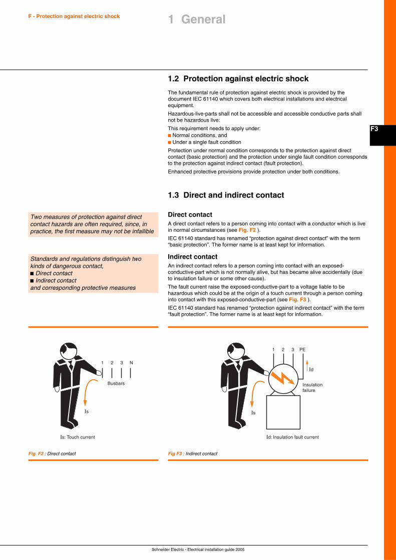
F3
Schneider Electric - Electrical installation guide 2005
F - Protection against electric shock
1.2 Protection against electric shock
The fundamental rule of protection against electric shock is provided by thedocument IEC 61140 which covers both electrical installations and electricalequipment.
Hazardous-live-parts shall not be accessible and accessible conductive parts shallnot be hazardous live:
This requirement needs to apply under:c Normal conditions, andc Under a single fault condition
Protection under normal condition corresponds to the protection against directcontact (basic protection) and the protection under single fault condition correspondsto the protection against indirect contact (fault protection).
Enhanced protective provisions provide protection under both conditions.
1.3 Direct and indirect contact
Direct contactA direct contact refers to a person coming into contact with a conductor which is livein normal circumstances (see Fig. F2 ).
IEC 61140 standard has renamed “protection against direct contact” with the term“basic protection”. The former name is at least kept for information.
Indirect contactAn indirect contact refers to a person coming into contact with an exposed-conductive-part which is not normally alive, but has became alive accidentally (dueto insulation failure or some other cause).
The fault current raise the exposed-conductive-part to a voltage liable to behazardous which could be at the origin of a touch current through a person cominginto contact with this exposed-conductive-part (see Fig. F3 ).
IEC 61140 standard has renamed “protection against indirect contact” with the term“fault protection”. The former name is at least kept for information.
Two measures of protection against directcontact hazards are often required, since, inpractice, the first measure may not be infallible
Standards and regulations distinguish twokinds of dangerous contact,c Direct contactc Indirect contactand corresponding protective measures
Busbars
1 2 3 N
Is: Touch current
Is
Insulationfailure
1 2 3 PE
Id
Id: Insulation fault current
Is
Fig. F2 : Direct contact Fig F3 : Indirect contact
1 General

Schneider Electric - Electrical installation guide 2005
F4
F - Protection against electric shock 2 Protection against direct contact
Two complementary measures are commonly used as protection against thedangers of direct contact:c The physical prevention of contact with live parts by barriers, insulation,inaccessibility, etc.c Additional protection in the event that a direct contact occurs, despite or due tofailure of the above measures. This protection is based on residual-current operatingdevice with a high sensitivity (I∆n i 30 mA) and a low operating time. These devicesare highly effective in the majority of case of direct contact.
2.1 Measures of protection against direct contact
Protection by the insulation of live partsThis protection consists of an insulation which complies with the relevant standards(see Fig. F4 ). Paints, lacquers and varnishes do not provide an adequate protection.
IEC and national standards frequentlydistinguish two protection:c Complete (insulation, enclosures)c Partial or particular
Fig. F4 : Inherent protection against direct contact by insulation of a 3-phase cable with outersheath
Fig. F5 : Example of isolation by envelope
Protection by means of barriers or enclosuresThis measure is in widespread use, since many components and materials areinstalled in cabinets, assemblies, control panels and distribution board (see Fig. F5 ).
To be considered as providing effective protection against direct contact hazards,these equipment must possess a degree of protection equal to at least IP 2X orIP XXB (see chapter E sub-clause 4.4).
Moreover, an opening in an enclosure (door, front panel, drawer, etc.) must only beremovable, open or withdrawn:c By means of a key or tool provided for this purpose, orc After complete isolation of the live parts in the enclosure, orc With the automatic interposition of another screen removable only with a key or atool. The metal enclosure and all metal removable screen must be bonded to theprotective earthing conductor of the installation.
Partial measures of protectionc Protection by means of obstacles, or by placing out of arm’s reachThis protection is reserved only to locations to which skilled or instructedpersons only have access. The erection of this protective measure is detailed inIEC 60364-4-41.
Particular measures of protectionc Protection by use of extra-low voltage SELV (Safety Extra-Low Voltage) or bylimitation of the energy of discharge.These measures are used only in low-power circuits, and in particularcircumstances, as described in section 3.5.
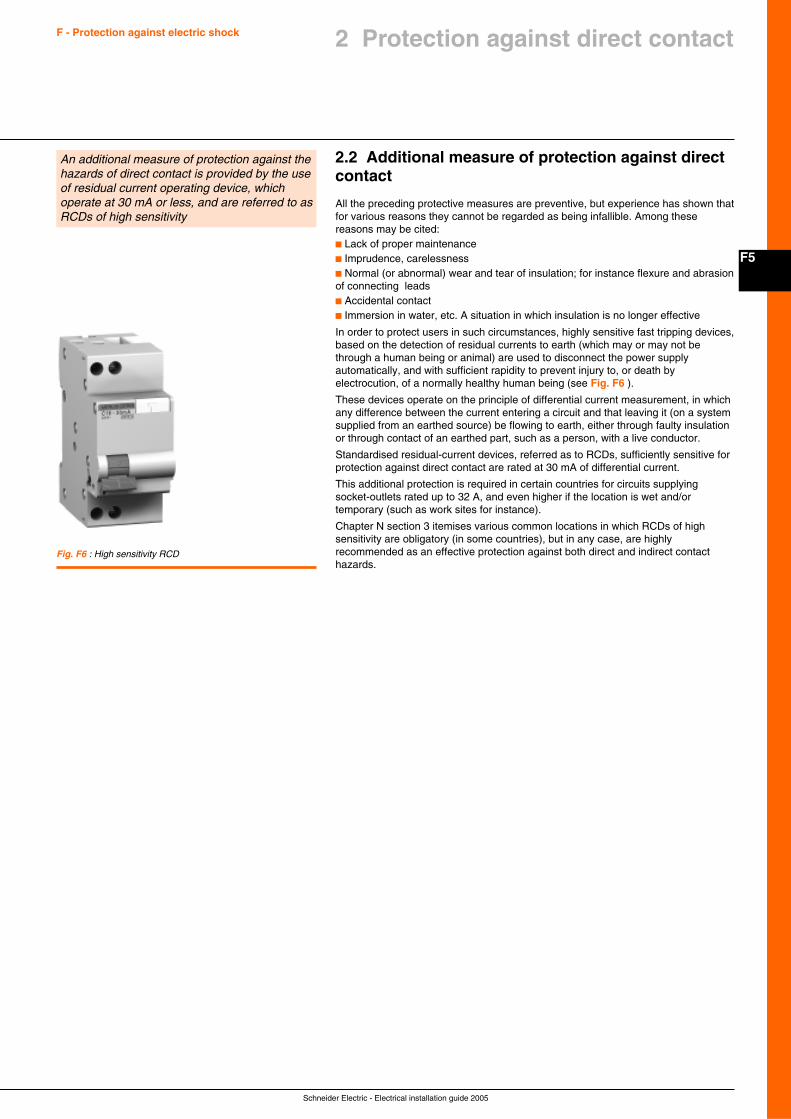
F5
Schneider Electric - Electrical installation guide 2005
F - Protection against electric shock
2.2 Additional measure of protection against directcontact
All the preceding protective measures are preventive, but experience has shown thatfor various reasons they cannot be regarded as being infallible. Among thesereasons may be cited:c Lack of proper maintenancec Imprudence, carelessnessc Normal (or abnormal) wear and tear of insulation; for instance flexure and abrasionof connecting leadsc Accidental contactc Immersion in water, etc. A situation in which insulation is no longer effective
In order to protect users in such circumstances, highly sensitive fast tripping devices,based on the detection of residual currents to earth (which may or may not bethrough a human being or animal) are used to disconnect the power supplyautomatically, and with sufficient rapidity to prevent injury to, or death byelectrocution, of a normally healthy human being (see Fig. F6 ).
These devices operate on the principle of differential current measurement, in whichany difference between the current entering a circuit and that leaving it (on a systemsupplied from an earthed source) be flowing to earth, either through faulty insulationor through contact of an earthed part, such as a person, with a live conductor.
Standardised residual-current devices, referred as to RCDs, sufficiently sensitive forprotection against direct contact are rated at 30 mA of differential current.
This additional protection is required in certain countries for circuits supplyingsocket-outlets rated up to 32 A, and even higher if the location is wet and/ortemporary (such as work sites for instance).
Chapter N section 3 itemises various common locations in which RCDs of highsensitivity are obligatory (in some countries), but in any case, are highlyrecommended as an effective protection against both direct and indirect contacthazards.
An additional measure of protection against thehazards of direct contact is provided by the useof residual current operating device, whichoperate at 30 mA or less, and are referred to asRCDs of high sensitivity
Fig. F6 : High sensitivity RCD
2 Protection against direct contact
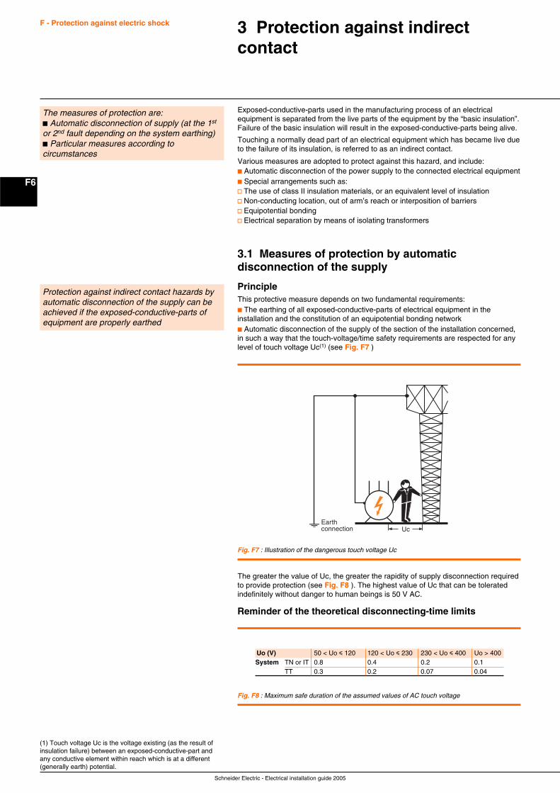
Schneider Electric - Electrical installation guide 2005
F6
F - Protection against electric shock 3 Protection against indirectcontact
Exposed-conductive-parts used in the manufacturing process of an electricalequipment is separated from the live parts of the equipment by the “basic insulation”.Failure of the basic insulation will result in the exposed-conductive-parts being alive.
Touching a normally dead part of an electrical equipment which has became live dueto the failure of its insulation, is referred to as an indirect contact.
Various measures are adopted to protect against this hazard, and include:c Automatic disconnection of the power supply to the connected electrical equipmentc Special arrangements such as:v The use of class II insulation materials, or an equivalent level of insulationv Non-conducting location, out of arm’s reach or interposition of barriersv Equipotential bondingv Electrical separation by means of isolating transformers
3.1 Measures of protection by automaticdisconnection of the supply
PrincipleThis protective measure depends on two fundamental requirements:c The earthing of all exposed-conductive-parts of electrical equipment in theinstallation and the constitution of an equipotential bonding networkc Automatic disconnection of the supply of the section of the installation concerned,in such a way that the touch-voltage/time safety requirements are respected for anylevel of touch voltage Uc(1) (see Fig. F7 )
The measures of protection are:c Automatic disconnection of supply (at the 1st
or 2nd fault depending on the system earthing)c Particular measures according tocircumstances
(1) Touch voltage Uc is the voltage existing (as the result ofinsulation failure) between an exposed-conductive-part andany conductive element within reach which is at a different(generally earth) potential.
Protection against indirect contact hazards byautomatic disconnection of the supply can beachieved if the exposed-conductive-parts ofequipment are properly earthed
UcEarthconnection
Fig. F7 : Illustration of the dangerous touch voltage Uc
Fig. F8 : Maximum safe duration of the assumed values of AC touch voltage
Uo (V) 50 < Uo i 120 120 < Uo i 230 230 < Uo i 400 Uo > 400System TN or IT 0.8 0.4 0.2 0.1
TT 0.3 0.2 0.07 0.04
The greater the value of Uc, the greater the rapidity of supply disconnection requiredto provide protection (see Fig. F8 ). The highest value of Uc that can be toleratedindefinitely without danger to human beings is 50 V AC.
Reminder of the theoretical disconnecting-time limits
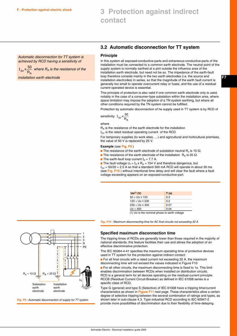
F7
Schneider Electric - Electrical installation guide 2005
F - Protection against electric shock
3.2 Automatic disconnection for TT system
PrincipleIn this system all exposed-conductive-parts and extraneous-conductive-parts of theinstallation must be connected to a common earth electrode. The neutral point of thesupply system is normally earthed at a pint outside the influence area of theinstallation earth electrode, but need not be so. The impedance of the earth-faultloop therefore consists mainly in the two earth electrodes (i.e. the source andinstallation electrodes) in series, so that the magnitude of the earth fault current isgenerally too small to operate overcurrent relay or fuses, and the use of a residualcurrent operated device is essential.
This principle of protection is also valid if one common earth electrode only is used,notably in the case of a consumer-type substation within the installation area, wherespace limitation may impose the adoption of a TN system earthing, but where allother conditions required by the TN system cannot be fulfilled.
Protection by automatic disconnection of he supply used in TT system is by RCD of
sensitivity:
I∆n Ri
50
A
whereRA is the resistance of the earth electrode for the installationI∆n is the rated residual operating current of the RCD
For temporary supplies (to work sites, …) and agricultural and horticultural premises,the value of 50 V is replaced by 25 V.
Example (see Fig. F9 )c The resistance of the earth electrode of substation neutral Rn is 10 Ω.c The resistance of the earth electrode of the installation RA is 20 Ω.c The earth-fault loop current Id = 7.7 A.c The fault voltage Ut = Id x RA = 154 V and therefore dangerous, butI∆n = 50/20 = 2.5 A so that a standard 300 mA RCD will operate in about 30 ms(see Fig. F10 ) without intentional time delay and will clear the fault where a faultvoltage exceeding appears on an exposed-conductive-part.
Fig. F10 : Maximum disconnecting time for AC final circuits not exceeding 32 A
123NPE
Rn = 10 Ω
Substationearthelectrode
Installationearthelectrode
RA = 20 Ω
Uf
Fig. F9 : Automatic disconnection of supply for TT system
Automatic disconnection for TT system isachieved by RCD having a sensitivity of
I∆n Ri
50
A where RA is the resistance of the
installation earth electrode
3 Protection against indirectcontact
(1) Uo is the nominal phase to earth voltage
Uo(1) (V) T (s)50 < Uo i 120 0.3120 < Uo i 230 0.2230 < Uo i 400 0.07Uo > 400 0.04
Specified maximum disconnection timeThe tripping times of RCDs are generally lower than those required in the majority ofnational standards; this feature facilities their use and allows the adoption of aneffective discriminative protection.
The IEC 60364-4-41 specifies the maximum operating time of protective devicesused in TT system for the protection against indirect contact:c For all final circuits with a rated current not exceeding 32 A, the maximumdisconnecting time will not exceed the values indicated in Figure F10c For all other circuits, the maximum disconnecting time is fixed to 1s. This limitenables discrimination between RCDs when installed on distribution circuits.RCD is a general term for all devices operating on the residual-current principle.RCCB (Residual Current Circuit-Breaker) as defined in IEC 61008 series is aspecific class of RCD.
Type G (general) and type S (Selective) of IEC 61008 have a tripping time/currentcharacteristics as shown in Figure F11 next page. These characteristics allow a certaindegree of selective tripping between the several combination of ratings and types, asshown later in sub-clause 4.3. Type industrial RCD according to IEC 60947-2provide more possibilities of discrimination due to their flexibility of time-delaying.

Schneider Electric - Electrical installation guide 2005
F8
F - Protection against electric shock
3.3 Automatic disconnection for TN systems
PrincipleIn this system all exposed and extraneous-conductive-parts of the installation areconnected directly to the earthed point of the power supply by protective conductors.
As noted in Chapter E Sub-clause 2.2, the way in which this direct connection iscarried out depends on whether the TN-C, TN-S, or TN-C-S method of implementingthe TN principle is used. In figure F12 the method TN-C is shown, in which theneutral conductor acts as both the Protective-Earth and Neutral (PEN) conductor. Inall TN systems, any insulation fault to earth results in a phase to neutral short-circuit.High fault current levels allow to use overcurrent protection but can give rise to touchvoltages exceeding 50% of the phase to neutral voltage at the fault position duringthe short disconnection time.
In practice for utility distribution network, earth electrodes are normally installed atregular intervals along the protective conductor (PE or PEN) of the network, whilethe consumer is often required to install an earth electrode at the service entrance.
On large installations additional earth electrodes dispersed around the premises areoften provided, in order to reduce the touch voltage as much as possible. In high-riseapartment blocks, all extraneous conductive parts are connected to the protectiveconductor at each level. In order to ensure adequate protection, the earth-faultcurrent
I Id or 0.8
UoZc
a=UoZs
u where
c Uo = nominal phase to neutral voltagec Zs = earth-fault current loop impedance, equal to the sum of the impedances of thesource, the live phase conductors to the fault position, the protective conductorsfrom the fault position back to the sourcec Zc = the faulty-circuit loop impedance (see “conventional method” Sub-clause 6.2)
Note: The path through earth electrodes back to the source will have (generally)much higher impedance values than those listed above, and need not be considered.c Id = the fault currentc Ia = current equal to the value required to operate the protective device in the timespecified
Example (see Fig. F12 )
The fault voltage Uf = =2302
115 V and is hazardous;
The fault loop impedance Zs=ZAB + ZBC + ZDE + ZEN + ZNA.If ZBC and ZDE are predominant, then:
ZsLS
= =2 64 3ρ . mΩ , so that
Id = =23064.3
3,576 A (≈ 22 In based on a NS 160 circuit-breaker).
The “instantaneous” magnetic trip unit adjustment of the circuit-breaker is many timeless than this short-circuit value, so that positive operation in the shortest possibletime is assured.
Note: Some authorities base such calculations on the assumption that a voltagedrop of 20% occurs in the part of the impedance loop BANE.
This method, which is recommended is explained in chapter F sub-clause 6.2“conventional method” and in this example will give an estimated fault current of
230 x 0.8 x 1064.3
2,816 A3= (≈ 18 In).
The automatic disconnection for TN system isachieved by overcurrent protective device orResidual Current Devices
Fig. F12 : Automatic disconnection in TN system
123PEN
NS160
A
F
N E
D C
B
Uf
35 mm2
50 m35 mm2
Fig. F11 : Maximum operating time of RCD’s
x I∆n 1 2 5 > 5Domestic Instantaneous 0.3 0.15 0.04 0.04
Type S 0.5 0.2 0.15 0.15Industrial Instantaneous 0.3 0.15 0.04 0.04
Time-delay (0.06) 0.5 0.2 0.15 0.15Time-delay (other) According to manufacturer
3 Protection against indirectcontact
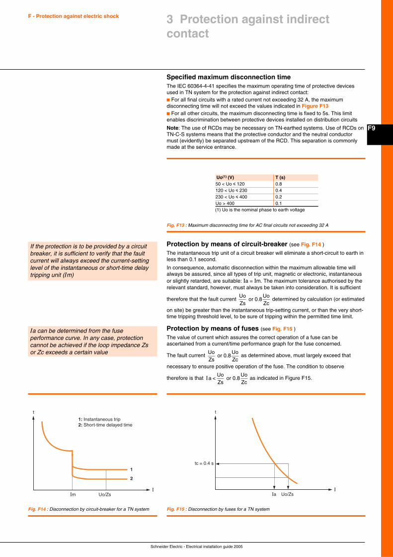
F9
Schneider Electric - Electrical installation guide 2005
F - Protection against electric shock
Specified maximum disconnection timeThe IEC 60364-4-41 specifies the maximum operating time of protective devicesused in TN system for the protection against indirect contact:c For all final circuits with a rated current not exceeding 32 A, the maximumdisconnecting time will not exceed the values indicated in Figure F13c For all other circuits, the maximum disconnecting time is fixed to 5s. This limitenables discrimination between protective devices installed on distribution circuits
Note: The use of RCDs may be necessary on TN-earthed systems. Use of RCDs onTN-C-S systems means that the protective conductor and the neutral conductormust (evidently) be separated upstream of the RCD. This separation is commonlymade at the service entrance.
Fig. F13 : Maximum disconnecting time for AC final circuits not exceeding 32 A
1
1: Instantaneous trip2: Short-time delayed time
Im Uo/ZsI
2
t
Ia Uo/Zs
t
tc = 0.4 s
I
If the protection is to be provided by a circuitbreaker, it is sufficient to verify that the faultcurrent will always exceed the current-settinglevel of the instantaneous or short-time delaytripping unit (Im)
Ia can be determined from the fuseperformance curve. In any case, protectioncannot be achieved if the loop impedance Zsor Zc exceeds a certain value
Fig. F14 : Disconnection by circuit-breaker for a TN system Fig. F15 : Disconnection by fuses for a TN system
3 Protection against indirectcontact
(1) Uo is the nominal phase to earth voltage
Uo(1) (V) T (s)50 < Uo i 120 0.8120 < Uo i 230 0.4230 < Uo i 400 0.2Uo > 400 0.1
Protection by means of circuit-breaker (see Fig. F14 )
The instantaneous trip unit of a circuit breaker will eliminate a short-circuit to earth inless than 0.1 second.
In consequence, automatic disconnection within the maximum allowable time willalways be assured, since all types of trip unit, magnetic or electronic, instantaneousor slightly retarded, are suitable: Ia = Im. The maximum tolerance authorised by therelevant standard, however, must always be taken into consideration. It is sufficient
therefore that the fault current UoZs
or 0.8UoZc
determined by calculation (or estimated
on site) be greater than the instantaneous trip-setting current, or than the very short-time tripping threshold level, to be sure of tripping within the permitted time limit.
Protection by means of fuses (see Fig. F15 )
The value of current which assures the correct operation of a fuse can beascertained from a current/time performance graph for the fuse concerned.
The fault current UoZs
or 0.8UoZc
as determined above, must largely exceed that
necessary to ensure positive operation of the fuse. The condition to observe
therefore is that Ia <UoZs
or 0.8UoZc
as indicated in Figure F15.
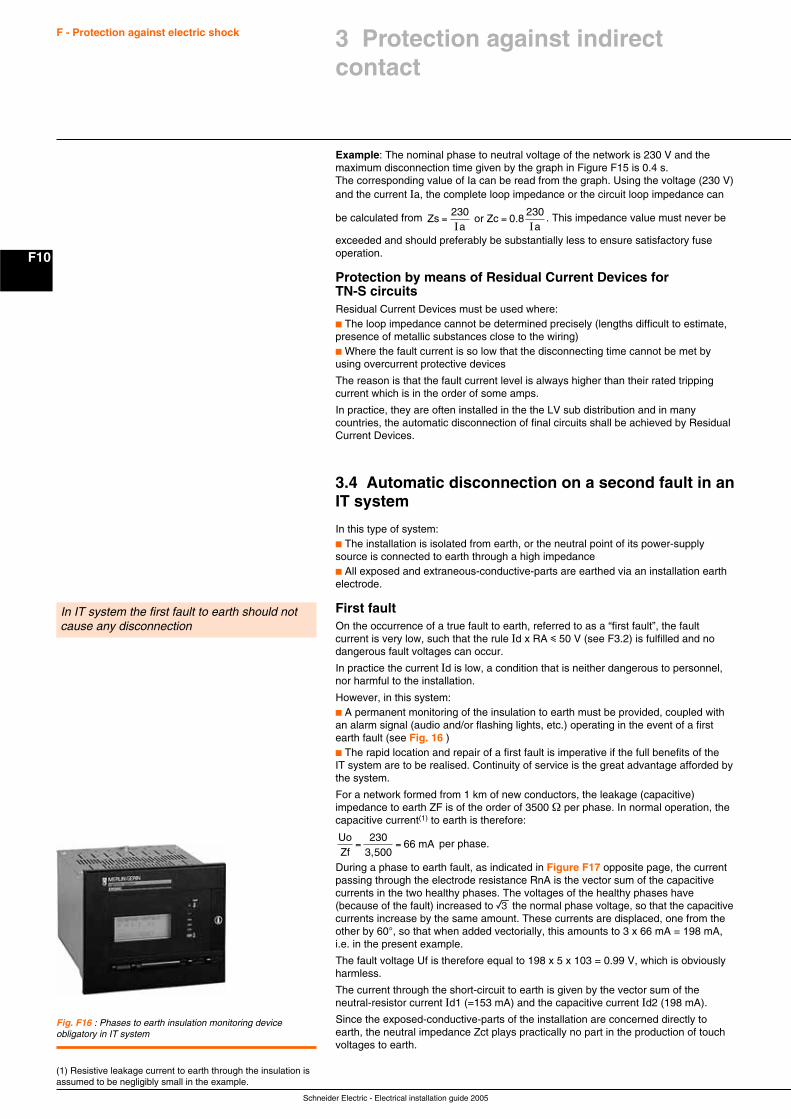
Schneider Electric - Electrical installation guide 2005
F10
F - Protection against electric shock
Example: The nominal phase to neutral voltage of the network is 230 V and themaximum disconnection time given by the graph in Figure F15 is 0.4 s.The corresponding value of Ia can be read from the graph. Using the voltage (230 V)and the current Ia, the complete loop impedance or the circuit loop impedance can
be calculated from Zsa a
= =230I I
or Zc 0.8230 . This impedance value must never be
exceeded and should preferably be substantially less to ensure satisfactory fuseoperation.
Protection by means of Residual Current Devices forTN-S circuitsResidual Current Devices must be used where:c The loop impedance cannot be determined precisely (lengths difficult to estimate,presence of metallic substances close to the wiring)c Where the fault current is so low that the disconnecting time cannot be met byusing overcurrent protective devices
The reason is that the fault current level is always higher than their rated trippingcurrent which is in the order of some amps.
In practice, they are often installed in the the LV sub distribution and in manycountries, the automatic disconnection of final circuits shall be achieved by ResidualCurrent Devices.
3.4 Automatic disconnection on a second fault in anIT system
In this type of system:c The installation is isolated from earth, or the neutral point of its power-supplysource is connected to earth through a high impedancec All exposed and extraneous-conductive-parts are earthed via an installation earthelectrode.
First faultOn the occurrence of a true fault to earth, referred to as a “first fault”, the faultcurrent is very low, such that the rule Id x RA i 50 V (see F3.2) is fulfilled and nodangerous fault voltages can occur.
In practice the current Id is low, a condition that is neither dangerous to personnel,nor harmful to the installation.
However, in this system:c A permanent monitoring of the insulation to earth must be provided, coupled withan alarm signal (audio and/or flashing lights, etc.) operating in the event of a firstearth fault (see Fig. 16 )c The rapid location and repair of a first fault is imperative if the full benefits of theIT system are to be realised. Continuity of service is the great advantage afforded bythe system.
For a network formed from 1 km of new conductors, the leakage (capacitive)impedance to earth ZF is of the order of 3500 Ω per phase. In normal operation, thecapacitive current(1) to earth is therefore:
UoZf
= =230
3,50066 mA per phase.
During a phase to earth fault, as indicated in Figure F17 opposite page, the currentpassing through the electrode resistance RnA is the vector sum of the capacitivecurrents in the two healthy phases. The voltages of the healthy phases have(because of the fault) increased to e the normal phase voltage, so that the capacitivecurrents increase by the same amount. These currents are displaced, one from theother by 60°, so that when added vectorially, this amounts to 3 x 66 mA = 198 mA,i.e. in the present example.
The fault voltage Uf is therefore equal to 198 x 5 x 103 = 0.99 V, which is obviouslyharmless.
The current through the short-circuit to earth is given by the vector sum of theneutral-resistor current Id1 (=153 mA) and the capacitive current Id2 (198 mA).
Since the exposed-conductive-parts of the installation are concerned directly toearth, the neutral impedance Zct plays practically no part in the production of touchvoltages to earth.
In IT system the first fault to earth should notcause any disconnection
Fig. F16 : Phases to earth insulation monitoring deviceobligatory in IT system
(1) Resistive leakage current to earth through the insulation isassumed to be negligibly small in the example.
3 Protection against indirectcontact
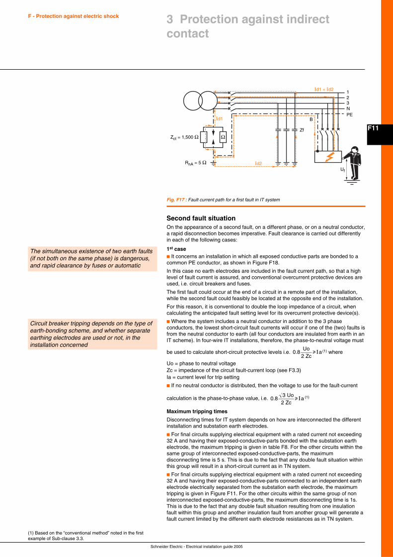
F11
Schneider Electric - Electrical installation guide 2005
F - Protection against electric shock
Second fault situationOn the appearance of a second fault, on a different phase, or on a neutral conductor,a rapid disconnection becomes imperative. Fault clearance is carried out differentlyin each of the following cases:
1st casec It concerns an installation in which all exposed conductive parts are bonded to acommon PE conductor, as shown in Figure F18.
In this case no earth electrodes are included in the fault current path, so that a highlevel of fault current is assured, and conventional overcurrent protective devices areused, i.e. circuit breakers and fuses.
The first fault could occur at the end of a circuit in a remote part of the installation,while the second fault could feasibly be located at the opposite end of the installation.
For this reason, it is conventional to double the loop impedance of a circuit, whencalculating the anticipated fault setting level for its overcurrent protective device(s).
c Where the system includes a neutral conductor in addition to the 3 phaseconductors, the lowest short-circuit fault currents will occur if one of the (two) faults isfrom the neutral conductor to earth (all four conductors are insulated from earth in anIT scheme). In four-wire IT installations, therefore, the phase-to-neutral voltage must
be used to calculate short-circuit protective levels i.e. 0.8
Uo2 Zc
au I (1) where
Uo = phase to neutral voltageZc = impedance of the circuit fault-current loop (see F3.3)Ia = current level for trip setting
c If no neutral conductor is distributed, then the voltage to use for the fault-current
calculation is the phase-to-phase value, i.e. 0.8
3 Uo2 Zc
au I (1)
Maximum tripping times
Disconnecting times for IT system depends on how are interconnected the differentinstallation and substation earth electrodes.
c For final circuits supplying electrical equipment with a rated current not exceeding32 A and having their exposed-conductive-parts bonded with the substation earthelectrode, the maximum tripping is given in table F8. For the other circuits within thesame group of interconnected exposed-conductive-parts, the maximumdisconnecting time is 5 s. This is due to the fact that any double fault situation withinthis group will result in a short-circuit current as in TN system.
c For final circuits supplying electrical equipment with a rated current not exceeding32 A and having their exposed-conductive-parts connected to an independent earthelectrode electrically separated from the substation earth electrode, the maximumtripping is given in Figure F11. For the other circuits within the same group of noninterconnected exposed-conductive-parts, the maximum disconnecting time is 1s.This is due to the fact that any double fault situation resulting from one insulationfault within this group and another insulation fault from another group will generate afault current limited by the different earth electrode resistances as in TN system.
Fig. F17 : Fault current path for a first fault in IT system
1
Id2
Id1
Id1 + Id2
23NPE
RnA = 5 Ω
Zct = 1,500 ΩZf
B
Uf
Ω
The simultaneous existence of two earth faults(if not both on the same phase) is dangerous,and rapid clearance by fuses or automatic
(1) Based on the “conventional method” noted in the firstexample of Sub-clause 3.3.
Circuit breaker tripping depends on the type ofearth-bonding scheme, and whether separateearthing electrodes are used or not, in theinstallation concerned
3 Protection against indirectcontact
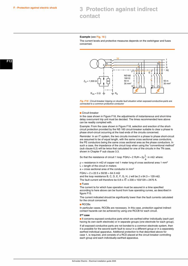
Schneider Electric - Electrical installation guide 2005
F12
F - Protection against electric shock
Example (see Fig. 18 )
The current levels and protective measures depends on the switchgear and fusesconcerned.
Fig. F18 : Circuit-breaker tripping on double fault situation when exposed-conductive-parts areconnected to a common protective conductor
1Id
23NPE
NS160160 Ω50 m35 mm2
50 m35 mm2
RnA = 5 Ω RA
Zct = 1,500 Ω
E
DHG
BAK
F
J
C
Ω
c Circuit-breakerIn the case shown in Figure F18, the adjustments of instantaneous and short-timedelay overcurrent trip unit must be decided. The times recommended here abovecan be readily complied with.
Example: From the case shown in Figure F18, selection and erection of the short-circuit protection provided by the NS 160 circuit-breaker suitable to clear a phase tophase short-circuit occurring at the load ends of the circuits concerned.
Reminder: In an IT system, the two circuits involved in a phase to phase short-circuitare assumed to be of equal length, with the same cross sectional area conductors,the PE conductors being the same cross sectional area as the phase conductors. Insuch a case, the impedance of the circuit loop when using the “conventional method”(sub clause 6.2) will be twice that calculated for one of the circuits in the TN case,shown in Chapter F sub clause 3.3.
So that the resistance of circuit 1 loop FGHJ RJHLa
= =2 2 in mρ Ω where:
ρ = resistance in mΩ of copper rod 1 meter long of cross sectional area 1 mm2
L = length of the circuit in metersa = cross sectional area of the conductor in mm2
FGHJ = 2 x 22.5 x 50/35 = 64.3 mΩand the loop resistance B, C, D, E, F, G, H, J will be 2 x 64.3 = 129 mΩ.The fault current will therefore be 0.8 x e x 230 x 103/129 = 2470 A.
c FusesThe current Ia for which fuse operation must be assured in a time specifiedaccording to here above can be found from fuse operating curves, as described infigure F15.
The current indicated should be significantly lower than the fault currents calculatedfor the circuit concerned.
c RCCBsIn particular cases, RCCBs are necessary. In this case, protection against indirectcontact hazards can be achieved by using one RCCB for each circuit.
2nd casec It concerns exposed conductive parts which are earthed either individually (each parthaving its own earth electrode) or in separate groups (one electrode for each group).
If all exposed conductive parts are not bonded to a common electrode system, thenit is possible for the second earth fault to occur in a different group or in a separatelyearthed individual apparatus. Additional protection to that described above forcase 1, is required, and consists of a RCD placed at the circuit breaker controllingeach group and each individually-earthed apparatus.
3 Protection against indirectcontact
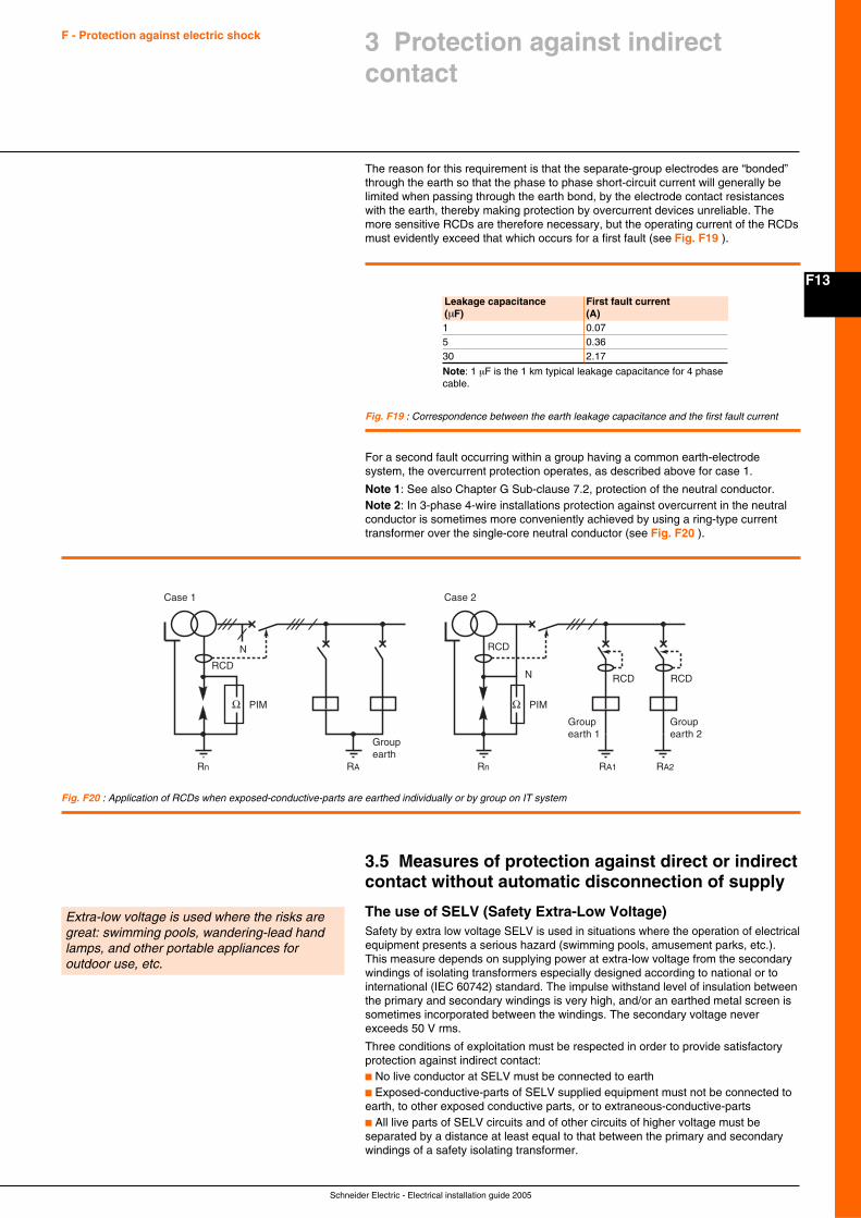
F13
Schneider Electric - Electrical installation guide 2005
F - Protection against electric shock
Fig. F19 : Correspondence between the earth leakage capacitance and the first fault current
Groupearth
Case 1
PIMΩ
N
RARn
RCD
Groupearth 2
Groupearth 1
Case 2
PIMΩ
N
RA1Rn RA2
RCD
RCD RCD
Fig. F20 : Application of RCDs when exposed-conductive-parts are earthed individually or by group on IT system
Leakage capacitance First fault current(µF) (A)1 0.075 0.3630 2.17
Note: 1 µF is the 1 km typical leakage capacitance for 4 phasecable.
The reason for this requirement is that the separate-group electrodes are “bonded”through the earth so that the phase to phase short-circuit current will generally belimited when passing through the earth bond, by the electrode contact resistanceswith the earth, thereby making protection by overcurrent devices unreliable. Themore sensitive RCDs are therefore necessary, but the operating current of the RCDsmust evidently exceed that which occurs for a first fault (see Fig. F19 ).
3 Protection against indirectcontact
Extra-low voltage is used where the risks aregreat: swimming pools, wandering-lead handlamps, and other portable appliances foroutdoor use, etc.
For a second fault occurring within a group having a common earth-electrodesystem, the overcurrent protection operates, as described above for case 1.
Note 1: See also Chapter G Sub-clause 7.2, protection of the neutral conductor.Note 2: In 3-phase 4-wire installations protection against overcurrent in the neutralconductor is sometimes more conveniently achieved by using a ring-type currenttransformer over the single-core neutral conductor (see Fig. F20 ).
3.5 Measures of protection against direct or indirectcontact without automatic disconnection of supply
The use of SELV (Safety Extra-Low Voltage)Safety by extra low voltage SELV is used in situations where the operation of electricalequipment presents a serious hazard (swimming pools, amusement parks, etc.).This measure depends on supplying power at extra-low voltage from the secondarywindings of isolating transformers especially designed according to national or tointernational (IEC 60742) standard. The impulse withstand level of insulation betweenthe primary and secondary windings is very high, and/or an earthed metal screen issometimes incorporated between the windings. The secondary voltage neverexceeds 50 V rms.
Three conditions of exploitation must be respected in order to provide satisfactoryprotection against indirect contact:c No live conductor at SELV must be connected to earthc Exposed-conductive-parts of SELV supplied equipment must not be connected toearth, to other exposed conductive parts, or to extraneous-conductive-partsc All live parts of SELV circuits and of other circuits of higher voltage must beseparated by a distance at least equal to that between the primary and secondarywindings of a safety isolating transformer.

Schneider Electric - Electrical installation guide 2005
F14
F - Protection against electric shock
These measures require that:c SELV circuits must use conduits exclusively provided for them, unless cables whichare insulated for the highest voltage of the other circuits are used for the SELV circuitsc Socket outlets for the SELV system must not have an earth-pin contact. TheSELV circuit plugs and sockets must be special, so that inadvertent connection to adifferent voltage level is not possible.
Note: In normal conditions, when the SELV voltage is less than 25 V, there is noneed to provide protection against direct contact hazards. Particular requirementsare indicated in Chapter N, Clause 3: “special locations”.
The use of PELV (Protection by Extra Low Voltage) (see Fig. 21 )
This system is for general use where low voltage is required, or preferred for safetyreasons, other than in the high-risk locations noted above. The conception is similarto that of the SELV system, but the secondary circuit is earthed at one point.
IEC 60364-4-41 defines precisely the significance of the reference PELV. Protectionagainst direct contact hazards is generally necessary, except when the equipmentis in the zone of equipotential bonding, and the nominal voltage does not exceed25 V rms, and the equipment is used in normally dry locations only, and large-areacontact with the human body is not expected. In all other cases, 6 V rms is themaximum permitted voltage, where no direct contact protection is provided.
Fig. F21 : Low-voltage supplies from a safety isolating transformer
Fig. F22 : Safety supply from a class II separation transformer
230 V / 24 V
FELV system (Functional Extra-Low Voltage)Where, for functional reasons, a voltage of 50 V or less is used, but not all of therequirements relating to SELV or PELV are fulfilled, appropriate measures describedin IEC 60364-4-41 must be taken to ensure protection against both direct andindirect contact hazards, according to the location and use of these circuits.
Note: Such conditions may, for example, be encountered when the circuit containsequipment (such as transformers, relays, remote-control switches, contactors)insufficiently insulated with respect to circuits at higher voltages.
The electrical separation of circuits (see Fig. 22 )
The principle of the electrical separation of circuits (generally single-phase circuits)for safety purposes is based on the following rationale.
The two conductors from the unearthed single-phase secondary winding of aseparation transformer are insulated from earth.
If a direct contact is made with one conductor, a very small current only will flow intothe person making contact, through the earth and back to the other conductor, viathe inherent capacitance of that conductor with respect to earth. Since the conductorcapacitance to earth is very small, the current is generally below the level of perception.As the length of circuit cable increases, the direct contact current will progressivelyincrease to a point where a dangerous electric shock will be experienced.
Even if a short length of cable precludes any danger from capacitive current, a lowvalue of insulation resistance with respect to earth can result in danger, since thecurrent path is then via the person making contact, through the earth and back to theother conductor through the low conductor-to-earth insulation resistance.
For these reasons, relatively short lengths of well insulated cables are essential inseparation systems.
Transformers are specially designed for this duty, with a high degree of insulationbetween primary and secondary windings, or with equivalent protection, such as anearthed metal screen between the windings. Construction of the transformer is toclass II insulation standards.
The electrical separation of circuits is suitablefor relatively short cable lengths and high levelsof insulation resistance. It is preferably used foran individual appliance
230 V/230 V
3 Protection against indirectcontact
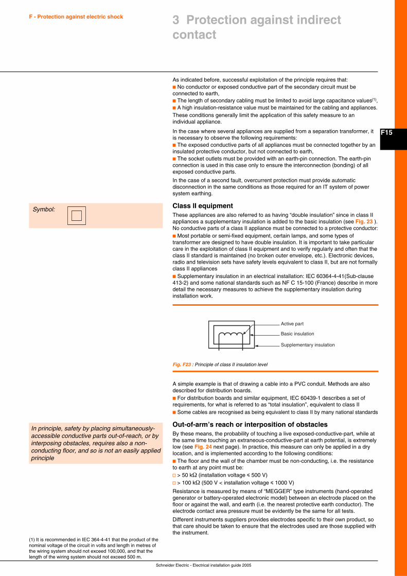
F15
Schneider Electric - Electrical installation guide 2005
F - Protection against electric shock 3 Protection against indirectcontact
(1) It is recommended in IEC 364-4-41 that the product of thenominal voltage of the circuit in volts and length in metres ofthe wiring system should not exceed 100,000, and that thelength of the wiring system should not exceed 500 m.
As indicated before, successful exploitation of the principle requires that:c No conductor or exposed conductive part of the secondary circuit must beconnected to earth,c The length of secondary cabling must be limited to avoid large capacitance values(1),c A high insulation-resistance value must be maintained for the cabling and appliances.These conditions generally limit the application of this safety measure to anindividual appliance.
In the case where several appliances are supplied from a separation transformer, itis necessary to observe the following requirements:c The exposed conductive parts of all appliances must be connected together by aninsulated protective conductor, but not connected to earth,c The socket outlets must be provided with an earth-pin connection. The earth-pinconnection is used in this case only to ensure the interconnection (bonding) of allexposed conductive parts.
In the case of a second fault, overcurrent protection must provide automaticdisconnection in the same conditions as those required for an IT system of powersystem earthing.
Class II equipmentThese appliances are also referred to as having “double insulation” since in class IIappliances a supplementary insulation is added to the basic insulation (see Fig. 23 ).No conductive parts of a class II appliance must be connected to a protective conductor:c Most portable or semi-fixed equipment, certain lamps, and some types oftransformer are designed to have double insulation. It is important to take particularcare in the exploitation of class II equipment and to verify regularly and often that theclass II standard is maintained (no broken outer envelope, etc.). Electronic devices,radio and television sets have safety levels equivalent to class II, but are not formallyclass II appliancesc Supplementary insulation in an electrical installation: IEC 60364-4-41(Sub-clause413-2) and some national standards such as NF C 15-100 (France) describe in moredetail the necessary measures to achieve the supplementary insulation duringinstallation work.
Symbol:
Fig. F23 : Principle of class II insulation level
Active part
Basic insulation
Supplementary insulation
A simple example is that of drawing a cable into a PVC conduit. Methods are alsodescribed for distribution boards.c For distribution boards and similar equipment, IEC 60439-1 describes a set ofrequirements, for what is referred to as “total insulation”, equivalent to class IIc Some cables are recognised as being equivalent to class II by many national standards
Out-of-arm’s reach or interposition of obstaclesBy these means, the probability of touching a live exposed-conductive-part, while atthe same time touching an extraneous-conductive-part at earth potential, is extremelylow (see Fig. 24 next page). In practice, this measure can only be applied in a drylocation, and is implemented according to the following conditions:c The floor and the wall of the chamber must be non-conducting, i.e. the resistanceto earth at any point must be:v > 50 kΩ (installation voltage i 500 V)v > 100 kΩ (500 V < installation voltage i 1000 V)
Resistance is measured by means of “MEGGER” type instruments (hand-operatedgenerator or battery-operated electronic model) between an electrode placed on thefloor or against the wall, and earth (i.e. the nearest protective earth conductor). Theelectrode contact area pressure must be evidently be the same for all tests.
Different instruments suppliers provides electrodes specific to their own product, sothat care should be taken to ensure that the electrodes used are those supplied withthe instrument.
In principle, safety by placing simultaneously-accessible conductive parts out-of-reach, or byinterposing obstacles, requires also a non-conducting floor, and so is not an easily appliedprinciple
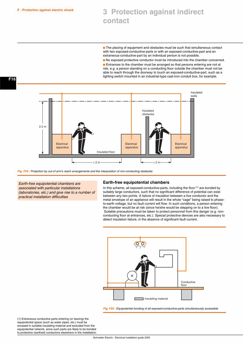
Schneider Electric - Electrical installation guide 2005
F16
F - Protection against electric shock
Earth-free equipotential chambersIn this scheme, all exposed-conductive-parts, including the floor (1) are bonded bysuitably large conductors, such that no significant difference of potential can existbetween any two points. A failure of insulation between a live conductor and themetal envelope of an appliance will result in the whole “cage” being raised to phase-to-earth voltage, but no fault current will flow. In such conditions, a person enteringthe chamber would be at risk (since he/she would be stepping on to a live floor). Suitable precautions must be taken to protect personnel from this danger (e.g. non-conducting floor at entrances, etc.). Special protective devices are also necessary todetect insulation failure, in the absence of significant fault current.
Fig. F24 : Protection by out-of arm’s reach arrangements and the interposition of non-conducting obstacles
Electricalapparatus
Electricalapparatus
< 2 m
Electricalapparatus
Insulatedwalls
Insulatedobstacles
> 2 m
Insulated floor
2.5 m
3 Protection against indirectcontact
Earth-free equipotential chambers areassociated with particular installations(laboratories, etc.) and give rise to a number ofpractical installation difficulties
c The placing of equipment and obstacles must be such that simultaneous contactwith two exposed-conductive-parts or with an exposed conductive-part and anextraneous-conductive-part by an individual person is not possible.c No exposed protective conductor must be introduced into the chamber concerned.c Entrances to the chamber must be arranged so that persons entering are not atrisk, e.g. a person standing on a conducting floor outside the chamber must not beable to reach through the doorway to touch an exposed-conductive-part, such as alighting switch mounted in an industrial-type cast-iron conduit box, for example.
(1) Extraneous conductive parts entering (or leaving) theequipotential space (such as water pipes, etc.) must beencased in suitable insulating material and excluded from theequipotential network, since such parts are likely to be bondedto protective (earthed) conductors elsewhere in the installation.
Fig. F25 : Equipotential bonding of all exposed-conductive-parts simultaneously accessible
Insulating material
Conductivefloor
M
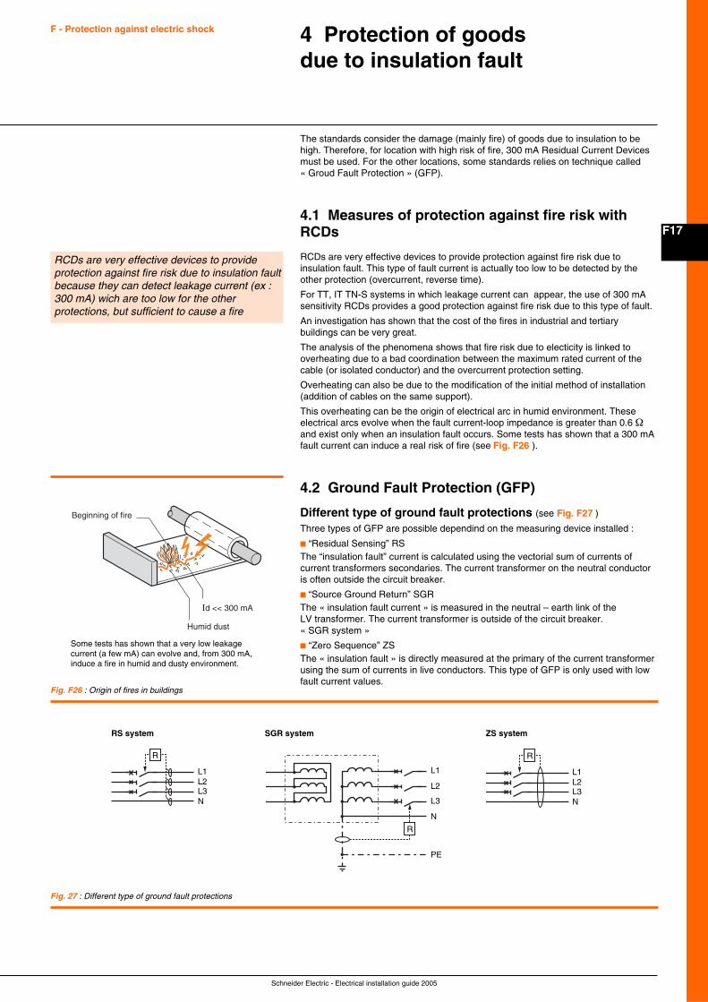
F17
Schneider Electric - Electrical installation guide 2005
F - Protection against electric shock 4 Protection of goodsdue to insulation fault
The standards consider the damage (mainly fire) of goods due to insulation to behigh. Therefore, for location with high risk of fire, 300 mA Residual Current Devicesmust be used. For the other locations, some standards relies on technique called« Groud Fault Protection » (GFP).
4.1 Measures of protection against fire risk withRCDs
RCDs are very effective devices to provide protection against fire risk due toinsulation fault. This type of fault current is actually too low to be detected by theother protection (overcurrent, reverse time).
For TT, IT TN-S systems in which leakage current can appear, the use of 300 mAsensitivity RCDs provides a good protection against fire risk due to this type of fault.
An investigation has shown that the cost of the fires in industrial and tertiarybuildings can be very great.
The analysis of the phenomena shows that fire risk due to electicity is linked tooverheating due to a bad coordination between the maximum rated current of thecable (or isolated conductor) and the overcurrent protection setting.
Overheating can also be due to the modification of the initial method of installation(addition of cables on the same support).
This overheating can be the origin of electrical arc in humid environment. Theseelectrical arcs evolve when the fault current-loop impedance is greater than 0.6 Ωand exist only when an insulation fault occurs. Some tests has shown that a 300 mAfault current can induce a real risk of fire (see Fig. F26 ).
4.2 Ground Fault Protection (GFP)
Different type of ground fault protections (see Fig. F27 )
Three types of GFP are possible dependind on the measuring device installed :
c “Residual Sensing” RSThe “insulation fault” current is calculated using the vectorial sum of currents ofcurrent transformers secondaries. The current transformer on the neutral conductoris often outside the circuit breaker.
c “Source Ground Return” SGRThe « insulation fault current » is measured in the neutral – earth link of theLV transformer. The current transformer is outside of the circuit breaker.« SGR system »
c “Zero Sequence” ZSThe « insulation fault » is directly measured at the primary of the current transformerusing the sum of currents in live conductors. This type of GFP is only used with lowfault current values.
Fig. F26 : Origin of fires in buildings
RCDs are very effective devices to provideprotection against fire risk due to insulation faultbecause they can detect leakage current (ex :300 mA) wich are too low for the otherprotections, but sufficient to cause a fire
Beginning of fire
Humid dust
Id << 300 mA
Some tests has shown that a very low leakagecurrent (a few mA) can evolve and, from 300 mA,induce a fire in humid and dusty environment.
L1L2L3N
R
L1
L2
L3
N
PE
R
L1L2L3N
R
RS system SGR system ZS system
Fig. 27 : Different type of ground fault protections
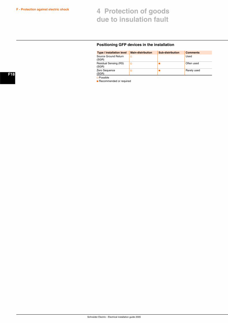
Schneider Electric - Electrical installation guide 2005
F18
F - Protection against electric shock
Positioning GFP devices in the installation
4 Protection of goodsdue to insulation fault
Type / installation level Main-distribution Sub-distribution CommentsSource Ground Return v Used(SGR)Residual Sensing (RS) v c Often used(SGR)Zero Sequence v c Rarely used(SGR)
v Possiblec Recommended or required
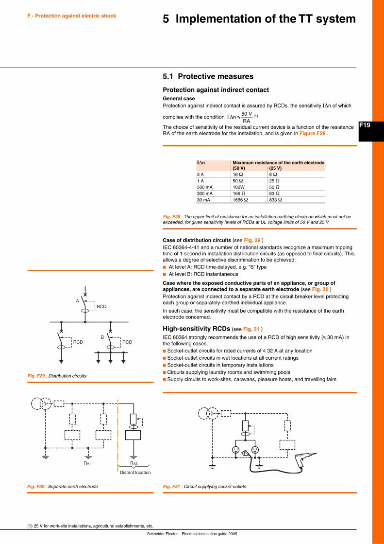
F19
Schneider Electric - Electrical installation guide 2005
F - Protection against electric shock 5 Implementation of the TT system
5.1 Protective measures
Protection against indirect contactGeneral caseProtection against indirect contact is assured by RCDs, the sensitivity I∆n of which
complies with the condition I∆n
50 VRA
i (1)
The choice of sensitivity of the residual current device is a function of the resistanceRA of the earth electrode for the installation, and is given in Figure F28 .
I∆n Maximum resistance of the earth electrode(50 V) (25 V)
3 A 16 Ω 8 Ω1 A 50 Ω 25 Ω500 mA 100W 50 Ω300 mA 166 Ω 83 Ω30 mA 1666 Ω 833 Ω
Fig. F28 : The upper limit of resistance for an installation earthing electrode which must not beexceeded, for given sensitivity levels of RCDs at UL voltage limits of 50 V and 25 V
Case of distribution circuits (see Fig. 29 )IEC 60364-4-41 and a number of national standards recognize a maximum trippingtime of 1 second in installation distribution circuits (as opposed to final circuits). Thisallows a degree of selective discrimination to be achieved:c At level A: RCD time-delayed, e.g. “S” typec At level B: RCD instantaneous
Case where the exposed conductive parts of an appliance, or group ofappliances, are connected to a separate earth electrode (see Fig. 30 )Protection against indirect contact by a RCD at the circuit breaker level protectingeach group or separately-earthed individual appliance.
In each case, the sensitivity must be compatible with the resistance of the earthelectrode concerned.
High-sensitivity RCDs (see Fig. 31 )
IEC 60364 strongly recommends the use of a RCD of high sensitivity (i 30 mA) inthe following cases:c Socket-outlet circuits for rated currents of i 32 A at any locationc Socket-outlet circuits in wet locations at all current ratingsc Socket-outlet circuits in temporary installationsc Circuits supplying laundry rooms and swimming poolsc Supply circuits to work-sites, caravans, pleasure boats, and travelling fairs
Fig. F29 : Distribution circuits
Fig. F30 : Separate earth electrode Fig. F31 : Circuit supplying socket-outlets
A
BRCDRCD
RCD
RA1 RA2
Distant location
(1) 25 V for work-site installations, agricultural establishments, etc.
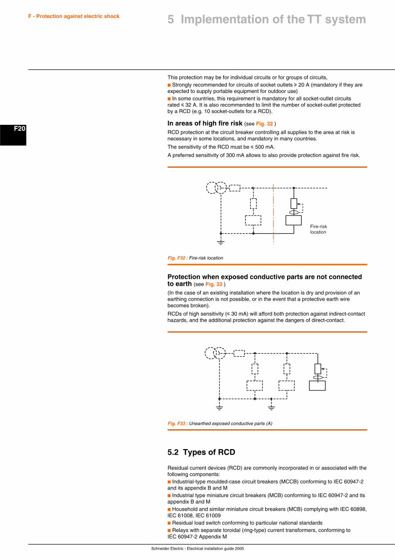
Schneider Electric - Electrical installation guide 2005
F20
F - Protection against electric shock
This protection may be for individual circuits or for groups of circuits,c Strongly recommended for circuits of socket outlets u 20 A (mandatory if they areexpected to supply portable equipment for outdoor use)c In some countries, this requirement is mandatory for all socket-outlet circuitsrated i 32 A. It is also recommended to limit the number of socket-outlet protectedby a RCD (e.g. 10 socket-outlets for a RCD).
In areas of high fire risk (see Fig. 32 )
RCD protection at the circuit breaker controlling all supplies to the area at risk isnecessary in some locations, and mandatory in many countries.
The sensitivity of the RCD must be i 500 mA.
A preferred sensitivity of 300 mA allows to also provide protection against fire risk.
Fig. F32 : Fire-risk location
Fire-risklocation
Fig. F33 : Unearthed exposed conductive parts (A)
Protection when exposed conductive parts are not connectedto earth (see Fig. 33 )
(In the case of an existing installation where the location is dry and provision of anearthing connection is not possible, or in the event that a protective earth wirebecomes broken).
RCDs of high sensitivity (i 30 mA) will afford both protection against indirect-contacthazards, and the additional protection against the dangers of direct-contact.
5.2 Types of RCD
Residual current devices (RCD) are commonly incorporated in or associated with thefollowing components:c Industrial-type moulded-case circuit breakers (MCCB) conforming to IEC 60947-2and its appendix B and Mc Industrial type miniature circuit breakers (MCB) conforming to IEC 60947-2 and itsappendix B and Mc Household and similar miniature circuit breakers (MCB) complying with IEC 60898,IEC 61008, IEC 61009c Residual load switch conforming to particular national standardsc Relays with separate toroidal (ring-type) current transformers, conforming toIEC 60947-2 Appendix M
5 Implementation of the TT system
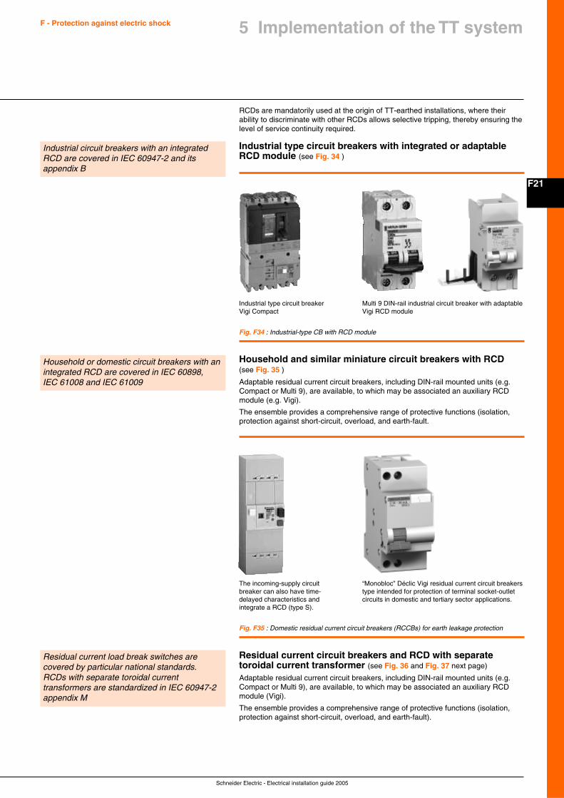
F21
Schneider Electric - Electrical installation guide 2005
F - Protection against electric shock
Fig. F34 : Industrial-type CB with RCD module
Fig. F35 : Domestic residual current circuit breakers (RCCBs) for earth leakage protection
RCDs are mandatorily used at the origin of TT-earthed installations, where theirability to discriminate with other RCDs allows selective tripping, thereby ensuring thelevel of service continuity required.
Industrial type circuit breakers with integrated or adaptableRCD module (see Fig. 34 )
Industrial circuit breakers with an integratedRCD are covered in IEC 60947-2 and itsappendix B
5 Implementation of the TT system
Industrial type circuit breakerVigi Compact
Multi 9 DIN-rail industrial circuit breaker with adaptableVigi RCD module
Household and similar miniature circuit breakers with RCD(see Fig. 35 )
Adaptable residual current circuit breakers, including DIN-rail mounted units (e.g.Compact or Multi 9), are available, to which may be associated an auxiliary RCDmodule (e.g. Vigi).
The ensemble provides a comprehensive range of protective functions (isolation,protection against short-circuit, overload, and earth-fault.
Household or domestic circuit breakers with anintegrated RCD are covered in IEC 60898,IEC 61008 and IEC 61009
The incoming-supply circuitbreaker can also have time-delayed characteristics andintegrate a RCD (type S).
“Monobloc” Déclic Vigi residual current circuit breakerstype intended for protection of terminal socket-outletcircuits in domestic and tertiary sector applications.
Residual current circuit breakers and RCD with separatetoroidal current transformer (see Fig. 36 and Fig. 37 next page)
Adaptable residual current circuit breakers, including DIN-rail mounted units (e.g.Compact or Multi 9), are available, to which may be associated an auxiliary RCDmodule (Vigi).
The ensemble provides a comprehensive range of protective functions (isolation,protection against short-circuit, overload, and earth-fault).
Residual current load break switches arecovered by particular national standards.RCDs with separate toroidal currenttransformers are standardized in IEC 60947-2appendix M
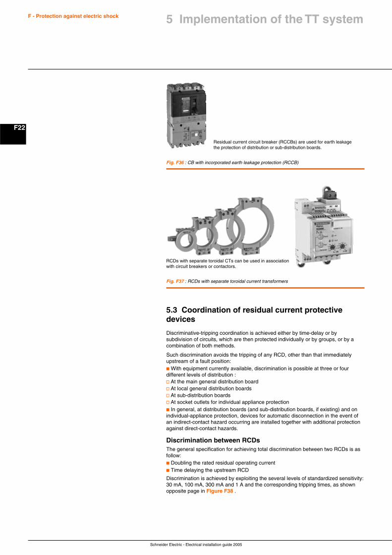
Schneider Electric - Electrical installation guide 2005
F22
F - Protection against electric shock
5.3 Coordination of residual current protectivedevices
Discriminative-tripping coordination is achieved either by time-delay or bysubdivision of circuits, which are then protected individually or by groups, or by acombination of both methods.
Such discrimination avoids the tripping of any RCD, other than that immediatelyupstream of a fault position:c With equipment currently available, discrimination is possible at three or fourdifferent levels of distribution :v At the main general distribution boardv At local general distribution boardsv At sub-distribution boardsv At socket outlets for individual appliance protectionc In general, at distribution boards (and sub-distribution boards, if existing) and onindividual-appliance protection, devices for automatic disconnection in the event ofan indirect-contact hazard occurring are installed together with additional protectionagainst direct-contact hazards.
Discrimination between RCDsThe general specification for achieving total discrimination between two RCDs is asfollow:c Doubling the rated residual operating currentc Time delaying the upstream RCD
Discrimination is achieved by exploiting the several levels of standardized sensitivity:30 mA, 100 mA, 300 mA and 1 A and the corresponding tripping times, as shownopposite page in Figure F38 .
Fig. F36 : CB with incorporated earth leakage protection (RCCB)
Fig. F37 : RCDs with separate toroidal current transformers
Residual current circuit breaker (RCCBs) are used for earth leakagethe protection of distribution or sub-distribution boards.
RCDs with separate toroidal CTs can be used in associationwith circuit breakers or contactors.
5 Implementation of the TT system
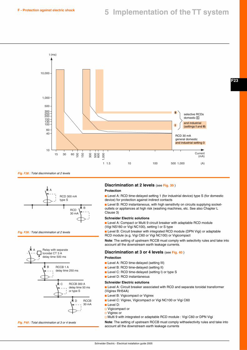
F23
Schneider Electric - Electrical installation guide 2005
F - Protection against electric shock 5 Implementation of the TT system
Discrimination at 2 levels (see Fig. 39 )
Protection
c Level A: RCD time-delayed setting 1 (for industrial device) type S (for domesticdevice) for protection against indirect contactsc Level B: RCD instantaneous, with high sensitivity on circuits supplying socket-outlets or appliances at high risk (washing machines, etc. See also Chapter LClause 3)
Schneider Electric solutionsc Level A: Compact or Multi 9 circuit breaker with adaptable RCD module(Vigi NS160 or Vigi NC100), setting I or S typec Level B: Circuit breaker with integrated RCD module (DPN Vigi) or adaptableRCD module (e.g. Vigi C60 or Vigi NC100) or Vigicompact
Note: The setting of upstream RCCB must comply with selectivity rules and take intoaccount all the downstream earth leakage currents.
Discrimination at 3 or 4 levels (see Fig. 40 )
Protection
c Level A: RCD time-delayed (setting III)c Level B: RCD time-delayed (setting II)c Level C: RCD time-delayed (setting I) or type Sc Level D: RCD instantaneous
Schneider Electric solutionsc Level A: Circuit breaker associated with RCD and separate toroidal transformer(Vigirex RH54A)c Level B: Vigicompact or Vigirexc Level C: Vigirex, Vigicompact or Vigi NC100 or Vigi C60c Level D:v Vigicompact orv Vigirex orv Multi 9 with integrated or adaptable RCD module : Vigi C60 or DPN Vigi
Note: The setting of upstream RCCB must comply withselectivity rules and take intoaccount all the downstream earth leakage currents
Fig. F38 : Total discrimination at 2 levels
t (ms)
40
10
60
100130150200250
500
1,000
300
10,000
15 Current(mA)
30
100
15060
300
500
600
1,00
0
1 1.5 10 100 500 1,000 (A)
I
II selective RCDsdomestic s
and industrial(settings I and II)
RCD 30 mAgeneral domesticand industrial setting 0
Fig. F39 : Total discrimination at 2 levels
A
B
RCD 300 mAtype S
RCD30 mA
Fig. F40 : Total discrimination at 3 or 4 levels
A
B
C
D
Relay with separatetoroidal CT 3 Adelay time 500 ms
RCCB 1 Adelay time 250 ms
RCCB30 mA
RCCB 300 Adelay time 50 msor type S
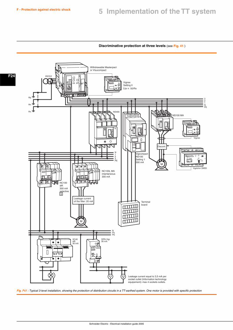
Schneider Electric - Electrical installation guide 2005
F24
F - Protection against electric shock 5 Implementation of the TT system
Fig. F41 : Typical 3-level installation, showing the protection of distribution circuits in a TT-earthed system. One motor is provided with specific protection
Discriminative protection at three levels (see Fig. 41 )
Withdrawable Masterpactor Visucompact
HV/LV
VigirexSetting III∆n i 50/RA
NC100diff.300 mAselective S
NC100L MAintantaneous300 mA
Leakage currentof the filter: 20 mA Terminal
board
Discont.
VigicompactNS100Setting 1300 mA
NS100 MA
Leakage current equal to 3,5 mA per socket outlet (Information technology equipement): max 4 sockets outlets.
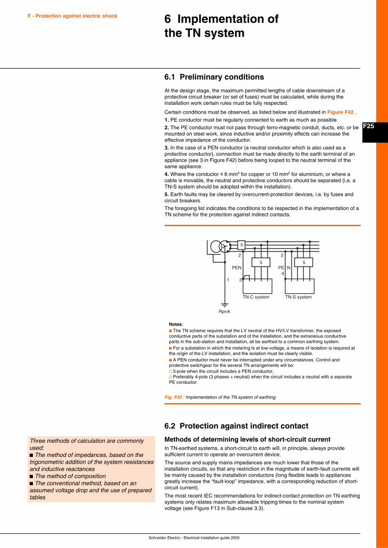
F25
Schneider Electric - Electrical installation guide 2005
F - Protection against electric shock 6 Implementation ofthe TN system
6.1 Preliminary conditions
At the design stage, the maximum permitted lengths of cable downstream of aprotective circuit breaker (or set of fuses) must be calculated, while during theinstallation work certain rules must be fully respected.
Certain conditions must be observed, as listed below and illustrated in Figure F42 .
1. PE conductor must be regularly connected to earth as much as possible.
2. The PE conductor must not pass through ferro-magnetic conduit, ducts, etc. or bemounted on steel work, since inductive and/or proximity effects can increase theeffective impedance of the conductor.
3. In the case of a PEN conductor (a neutral conductor which is also used as aprotective conductor), connection must be made directly to the earth terminal of anappliance (see 3 in Figure F42) before being looped to the neutral terminal of thesame appliance.
4. Where the conductor i 6 mm2 for copper or 10 mm2 for aluminium, or where acable is movable, the neutral and protective conductors should be separated (i.e. aTN-S system should be adopted within the installation).
5. Earth faults may be cleared by overcurrent-protection devices, i.e. by fuses andcircuit breakers.
The foregoing list indicates the conditions to be respected in the implementation of aTN scheme for the protection against indirect contacts.
Fig. F42 : Implementation of the TN system of earthing
Notes:c The TN scheme requires that the LV neutral of the HV/LV transformer, the exposedconductive parts of the substation and of the installation, and the extraneous conductiveparts in the sub-station and installation, all be earthed to a common earthing system.c For a substation in which the metering is at low-voltage, a means of isolation is required atthe origin of the LV installation, and the isolation must be clearly visible.c A PEN conductor must never be interrupted under any circumstances. Control andprotective switchgear for the several TN arrangements will be:v 3-pole when the circuit includes a PEN conductor,v Preferably 4-pole (3 phases + neutral) when the circuit includes a neutral with a separatePE conductor.
RpnA
PEN
TN-C system TN-S system
PE N
34
5
5
2 2
5
1
Three methods of calculation are commonlyused:c The method of impedances, based on thetrigonometric addition of the system resistancesand inductive reactancesc The method of compositionc The conventional method, based on anassumed voltage drop and the use of preparedtables
6.2 Protection against indirect contact
Methods of determining levels of short-circuit currentIn TN-earthed systems, a short-circuit to earth will, in principle, always providesufficient current to operate an overcurrent device.
The source and supply mains impedances are much lower that those of theinstallation circuits, so that any restriction in the magnitude of earth-fault currents willbe mainly caused by the installation conductors (long flexible leads to appliancesgreatly increase the “fault-loop” impedance, with a corresponding reduction of short-circuit current).
The most recent IEC recommendations for indirect-contact protection on TN earthingsystems only relates maximum allowable tripping times to the nominal systemvoltage (see Figure F13 in Sub-clause 3.3).
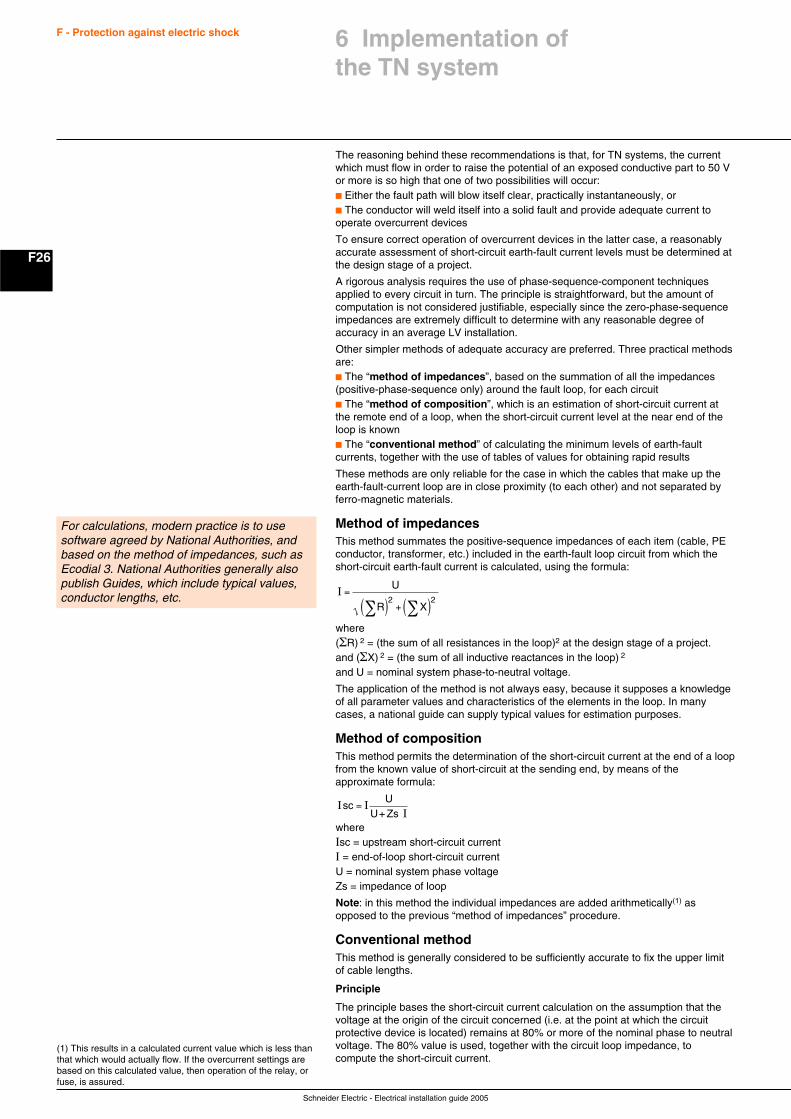
Schneider Electric - Electrical installation guide 2005
F26
F - Protection against electric shock
The reasoning behind these recommendations is that, for TN systems, the currentwhich must flow in order to raise the potential of an exposed conductive part to 50 Vor more is so high that one of two possibilities will occur:c Either the fault path will blow itself clear, practically instantaneously, orc The conductor will weld itself into a solid fault and provide adequate current tooperate overcurrent devices
To ensure correct operation of overcurrent devices in the latter case, a reasonablyaccurate assessment of short-circuit earth-fault current levels must be determined atthe design stage of a project.
A rigorous analysis requires the use of phase-sequence-component techniquesapplied to every circuit in turn. The principle is straightforward, but the amount ofcomputation is not considered justifiable, especially since the zero-phase-sequenceimpedances are extremely difficult to determine with any reasonable degree ofaccuracy in an average LV installation.
Other simpler methods of adequate accuracy are preferred. Three practical methodsare:c The “method of impedances”, based on the summation of all the impedances(positive-phase-sequence only) around the fault loop, for each circuitc The “method of composition”, which is an estimation of short-circuit current atthe remote end of a loop, when the short-circuit current level at the near end of theloop is knownc The “conventional method” of calculating the minimum levels of earth-faultcurrents, together with the use of tables of values for obtaining rapid results
These methods are only reliable for the case in which the cables that make up theearth-fault-current loop are in close proximity (to each other) and not separated byferro-magnetic materials.
Method of impedancesThis method summates the positive-sequence impedances of each item (cable, PEconductor, transformer, etc.) included in the earth-fault loop circuit from which theshort-circuit earth-fault current is calculated, using the formula:
I =
( ) + ( )∑ ∑
U
R X2 2
where(ΣR) 2 = (the sum of all resistances in the loop)2 at the design stage of a project.and (ΣX) 2 = (the sum of all inductive reactances in the loop) 2
and U = nominal system phase-to-neutral voltage.
The application of the method is not always easy, because it supposes a knowledgeof all parameter values and characteristics of the elements in the loop. In manycases, a national guide can supply typical values for estimation purposes.
Method of compositionThis method permits the determination of the short-circuit current at the end of a loopfrom the known value of short-circuit at the sending end, by means of theapproximate formula:
I II
scU
=U+ Zs
whereIsc = upstream short-circuit currentI = end-of-loop short-circuit currentU = nominal system phase voltageZs = impedance of loop
Note: in this method the individual impedances are added arithmetically(1) asopposed to the previous “method of impedances” procedure.
Conventional methodThis method is generally considered to be sufficiently accurate to fix the upper limitof cable lengths.
Principle
The principle bases the short-circuit current calculation on the assumption that thevoltage at the origin of the circuit concerned (i.e. at the point at which the circuitprotective device is located) remains at 80% or more of the nominal phase to neutralvoltage. The 80% value is used, together with the circuit loop impedance, tocompute the short-circuit current.
For calculations, modern practice is to usesoftware agreed by National Authorities, andbased on the method of impedances, such asEcodial 3. National Authorities generally alsopublish Guides, which include typical values,conductor lengths, etc.
(1) This results in a calculated current value which is less thanthat which would actually flow. If the overcurrent settings arebased on this calculated value, then operation of the relay, orfuse, is assured.
6 Implementation ofthe TN system
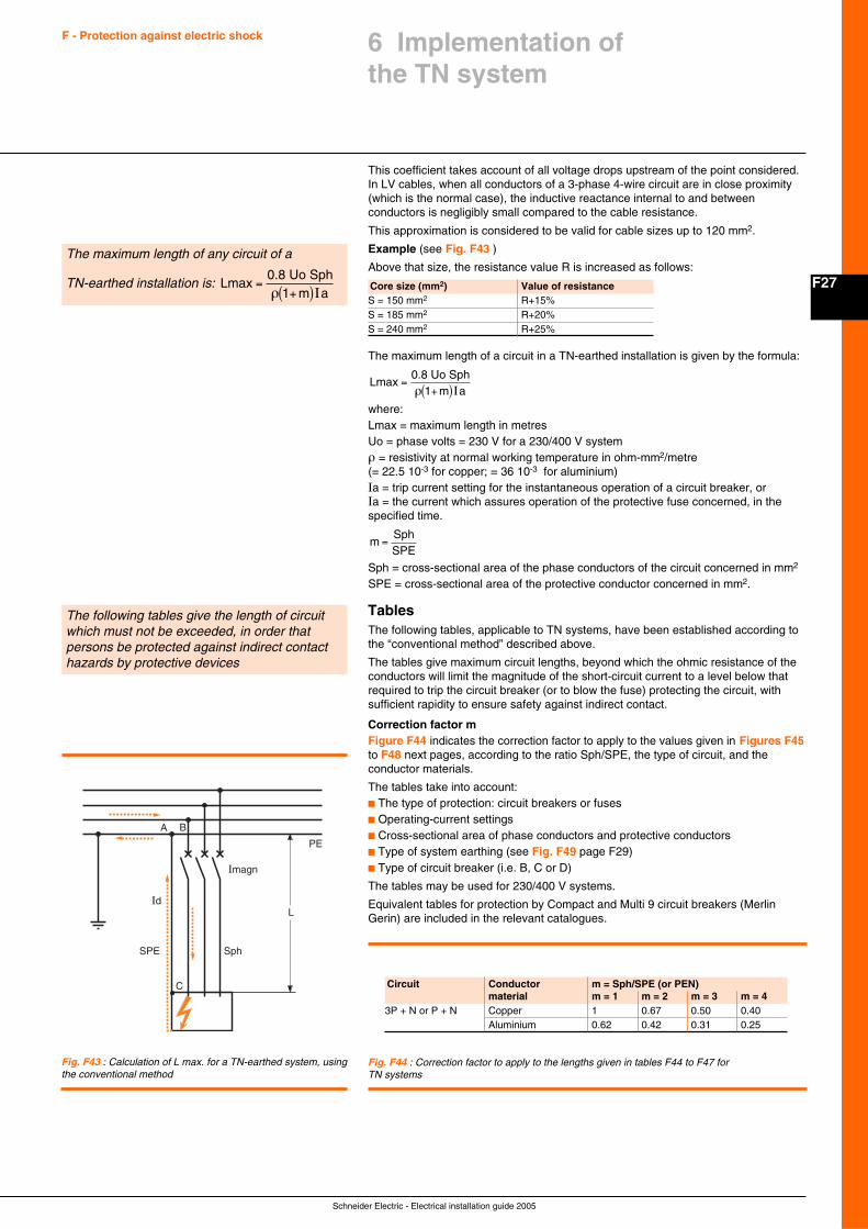
F27
Schneider Electric - Electrical installation guide 2005
F - Protection against electric shock 6 Implementation ofthe TN system
This coefficient takes account of all voltage drops upstream of the point considered.In LV cables, when all conductors of a 3-phase 4-wire circuit are in close proximity(which is the normal case), the inductive reactance internal to and betweenconductors is negligibly small compared to the cable resistance.
This approximation is considered to be valid for cable sizes up to 120 mm2.
Example (see Fig. F43 )
Above that size, the resistance value R is increased as follows:The maximum length of any circuit of a
TN-earthed installation is: Lm a
max0.8 Uo Sph
=+( )ρ 1 I
Fig. F43 : Calculation of L max. for a TN-earthed system, usingthe conventional method
Core size (mm2) Value of resistanceS = 150 mm2 R+15%S = 185 mm2 R+20%S = 240 mm2 R+25%
Imagn
IdL
C
PE
SPE Sph
A B
The maximum length of a circuit in a TN-earthed installation is given by the formula:
Lm a
max0.8 Uo Sph
=+( )ρ 1 I
where:Lmax = maximum length in metresUo = phase volts = 230 V for a 230/400 V systemρ = resistivity at normal working temperature in ohm-mm2/metre(= 22.5 10-3 for copper; = 36 10-3 for aluminium)Ia = trip current setting for the instantaneous operation of a circuit breaker, orIa = the current which assures operation of the protective fuse concerned, in thespecified time.
mSphSPE
=
Sph = cross-sectional area of the phase conductors of the circuit concerned in mm2
SPE = cross-sectional area of the protective conductor concerned in mm2.
TablesThe following tables, applicable to TN systems, have been established according tothe “conventional method” described above.
The tables give maximum circuit lengths, beyond which the ohmic resistance of theconductors will limit the magnitude of the short-circuit current to a level below thatrequired to trip the circuit breaker (or to blow the fuse) protecting the circuit, withsufficient rapidity to ensure safety against indirect contact.
Correction factor mFigure F44 indicates the correction factor to apply to the values given in Figures F45to F48 next pages, according to the ratio Sph/SPE, the type of circuit, and theconductor materials.
The tables take into account:c The type of protection: circuit breakers or fusesc Operating-current settingsc Cross-sectional area of phase conductors and protective conductorsc Type of system earthing (see Fig. F49 page F29)c Type of circuit breaker (i.e. B, C or D)
The tables may be used for 230/400 V systems.
Equivalent tables for protection by Compact and Multi 9 circuit breakers (MerlinGerin) are included in the relevant catalogues.
Fig. F44 : Correction factor to apply to the lengths given in tables F44 to F47 forTN systems
Circuit Conductor m = Sph/SPE (or PEN)material m = 1 m = 2 m = 3 m = 4
3P + N or P + N Copper 1 0.67 0.50 0.40Aluminium 0.62 0.42 0.31 0.25
The following tables give the length of circuitwhich must not be exceeded, in order thatpersons be protected against indirect contacthazards by protective devices
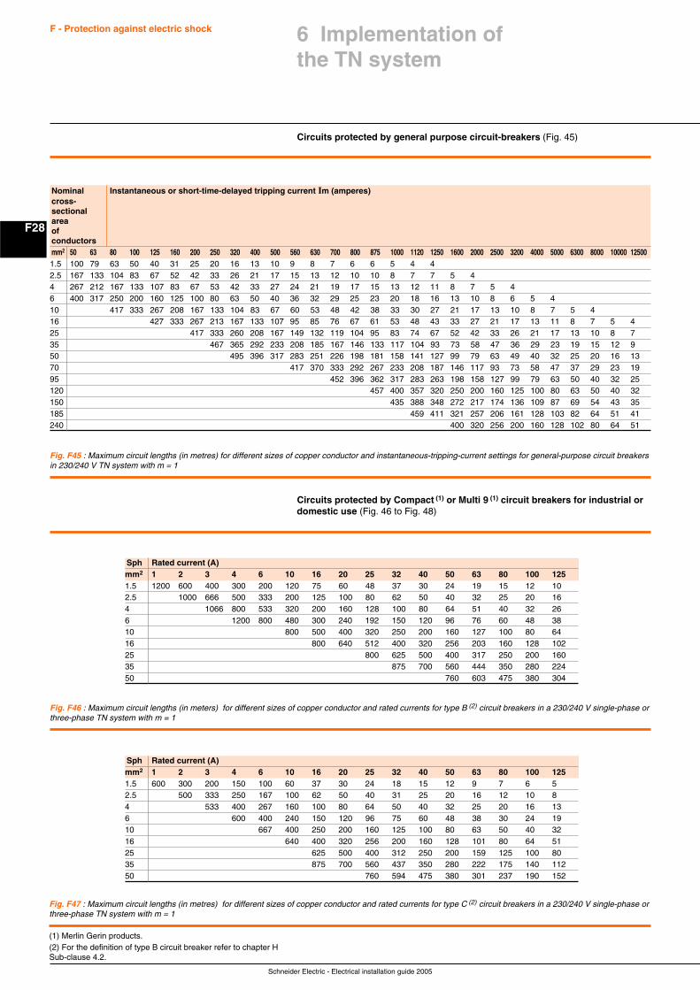
Schneider Electric - Electrical installation guide 2005
F28
F - Protection against electric shock
Circuits protected by general purpose circuit-breakers (Fig. 45)
Nominal Instantaneous or short-time-delayed tripping current Im (amperes)cross-sectionalareaofconductorsmm2 50 63 80 100 125 160 200 250 320 400 500 560 630 700 800 875 1000 1120 1250 1600 2000 2500 3200 4000 5000 6300 8000 10000 125001.5 100 79 63 50 40 31 25 20 16 13 10 9 8 7 6 6 5 4 42.5 167 133 104 83 67 52 42 33 26 21 17 15 13 12 10 10 8 7 7 5 44 267 212 167 133 107 83 67 53 42 33 27 24 21 19 17 15 13 12 11 8 7 5 46 400 317 250 200 160 125 100 80 63 50 40 36 32 29 25 23 20 18 16 13 10 8 6 5 410 417 333 267 208 167 133 104 83 67 60 53 48 42 38 33 30 27 21 17 13 10 8 7 5 416 427 333 267 213 167 133 107 95 85 76 67 61 53 48 43 33 27 21 17 13 11 8 7 5 425 417 333 260 208 167 149 132 119 104 95 83 74 67 52 42 33 26 21 17 13 10 8 735 467 365 292 233 208 185 167 146 133 117 104 93 73 58 47 36 29 23 19 15 12 950 495 396 317 283 251 226 198 181 158 141 127 99 79 63 49 40 32 25 20 16 1370 417 370 333 292 267 233 208 187 146 117 93 73 58 47 37 29 23 1995 452 396 362 317 283 263 198 158 127 99 79 63 50 40 32 25120 457 400 357 320 250 200 160 125 100 80 63 50 40 32150 435 388 348 272 217 174 136 109 87 69 54 43 35185 459 411 321 257 206 161 128 103 82 64 51 41240 400 320 256 200 160 128 102 80 64 51
Circuits protected by Compact (1) or Multi 9 (1) circuit breakers for industrial ordomestic use (Fig. 46 to Fig. 48)
Fig. F45 : Maximum circuit lengths (in metres) for different sizes of copper conductor and instantaneous-tripping-current settings for general-purpose circuit breakersin 230/240 V TN system with m = 1
Sph Rated current (A)mm2 1 2 3 4 6 10 16 20 25 32 40 50 63 80 100 1251.5 1200 600 400 300 200 120 75 60 48 37 30 24 19 15 12 102.5 1000 666 500 333 200 125 100 80 62 50 40 32 25 20 164 1066 800 533 320 200 160 128 100 80 64 51 40 32 266 1200 800 480 300 240 192 150 120 96 76 60 48 3810 800 500 400 320 250 200 160 127 100 80 6416 800 640 512 400 320 256 203 160 128 10225 800 625 500 400 317 250 200 16035 875 700 560 444 350 280 22450 760 603 475 380 304
Fig. F46 : Maximum circuit lengths (in meters) for different sizes of copper conductor and rated currents for type B (2) circuit breakers in a 230/240 V single-phase orthree-phase TN system with m = 1
(1) Merlin Gerin products.(2) For the definition of type B circuit breaker refer to chapter HSub-clause 4.2.
Sph Rated current (A)mm2 1 2 3 4 6 10 16 20 25 32 40 50 63 80 100 1251.5 600 300 200 150 100 60 37 30 24 18 15 12 9 7 6 52.5 500 333 250 167 100 62 50 40 31 25 20 16 12 10 84 533 400 267 160 100 80 64 50 40 32 25 20 16 136 600 400 240 150 120 96 75 60 48 38 30 24 1910 667 400 250 200 160 125 100 80 63 50 40 3216 640 400 320 256 200 160 128 101 80 64 5125 625 500 400 312 250 200 159 125 100 8035 875 700 560 437 350 280 222 175 140 11250 760 594 475 380 301 237 190 152
Fig. F47 : Maximum circuit lengths (in metres) for different sizes of copper conductor and rated currents for type C (2) circuit breakers in a 230/240 V single-phase orthree-phase TN system with m = 1
6 Implementation ofthe TN system
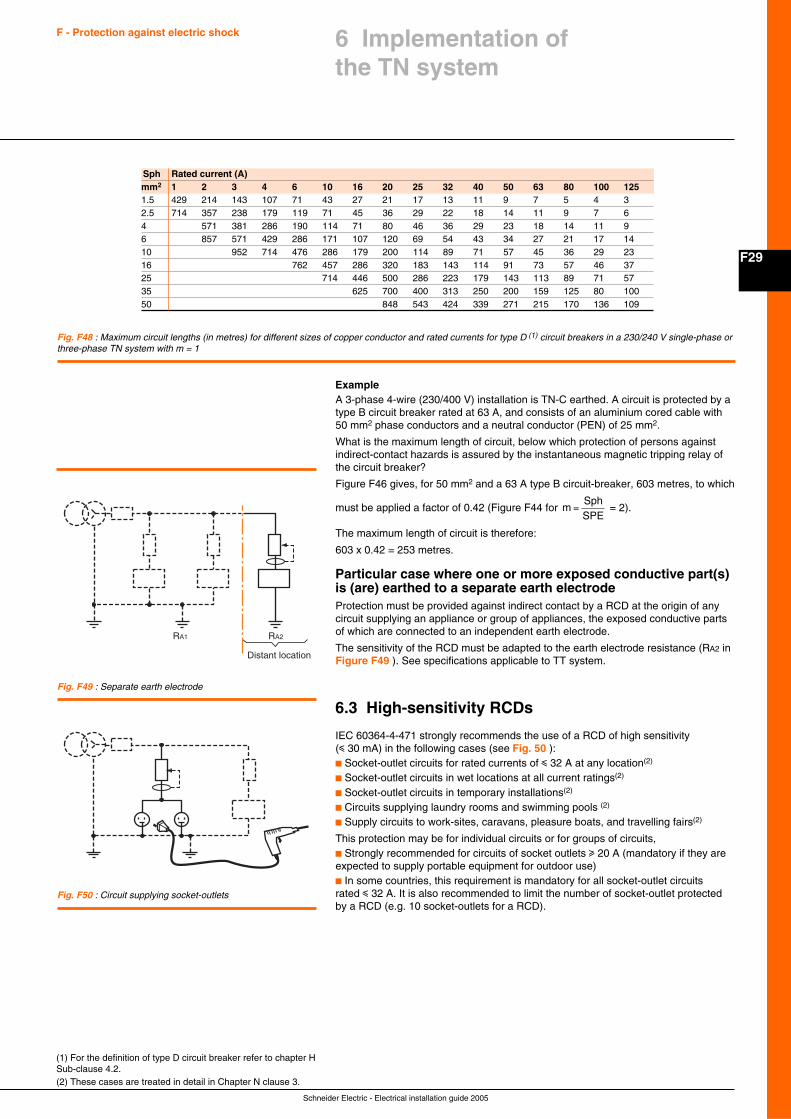
F29
Schneider Electric - Electrical installation guide 2005
F - Protection against electric shock 6 Implementation ofthe TN system
ExampleA 3-phase 4-wire (230/400 V) installation is TN-C earthed. A circuit is protected by atype B circuit breaker rated at 63 A, and consists of an aluminium cored cable with50 mm2 phase conductors and a neutral conductor (PEN) of 25 mm2.
What is the maximum length of circuit, below which protection of persons againstindirect-contact hazards is assured by the instantaneous magnetic tripping relay ofthe circuit breaker?
Figure F46 gives, for 50 mm2 and a 63 A type B circuit-breaker, 603 metres, to which
must be applied a factor of 0.42 (Figure F44 for mSphSPE
= = 2).
The maximum length of circuit is therefore:
603 x 0.42 = 253 metres.
Particular case where one or more exposed conductive part(s)is (are) earthed to a separate earth electrodeProtection must be provided against indirect contact by a RCD at the origin of anycircuit supplying an appliance or group of appliances, the exposed conductive partsof which are connected to an independent earth electrode.
The sensitivity of the RCD must be adapted to the earth electrode resistance (RA2 inFigure F49 ). See specifications applicable to TT system.
6.3 High-sensitivity RCDs
IEC 60364-4-471 strongly recommends the use of a RCD of high sensitivity(i 30 mA) in the following cases (see Fig. 50 ):c Socket-outlet circuits for rated currents of i 32 A at any location(2)
c Socket-outlet circuits in wet locations at all current ratings(2)
c Socket-outlet circuits in temporary installations(2)
c Circuits supplying laundry rooms and swimming pools (2)
c Supply circuits to work-sites, caravans, pleasure boats, and travelling fairs(2)
This protection may be for individual circuits or for groups of circuits,c Strongly recommended for circuits of socket outlets u 20 A (mandatory if they areexpected to supply portable equipment for outdoor use)c In some countries, this requirement is mandatory for all socket-outlet circuitsrated i 32 A. It is also recommended to limit the number of socket-outlet protectedby a RCD (e.g. 10 socket-outlets for a RCD).
Sph Rated current (A)mm2 1 2 3 4 6 10 16 20 25 32 40 50 63 80 100 1251.5 429 214 143 107 71 43 27 21 17 13 11 9 7 5 4 32.5 714 357 238 179 119 71 45 36 29 22 18 14 11 9 7 64 571 381 286 190 114 71 80 46 36 29 23 18 14 11 96 857 571 429 286 171 107 120 69 54 43 34 27 21 17 1410 952 714 476 286 179 200 114 89 71 57 45 36 29 2316 762 457 286 320 183 143 114 91 73 57 46 3725 714 446 500 286 223 179 143 113 89 71 5735 625 700 400 313 250 200 159 125 80 10050 848 543 424 339 271 215 170 136 109
Fig. F48 : Maximum circuit lengths (in metres) for different sizes of copper conductor and rated currents for type D (1) circuit breakers in a 230/240 V single-phase orthree-phase TN system with m = 1
(1) For the definition of type D circuit breaker refer to chapter HSub-clause 4.2.(2) These cases are treated in detail in Chapter N clause 3.
Fig. F49 : Separate earth electrode
RA1 RA2
Distant location
Fig. F50 : Circuit supplying socket-outlets
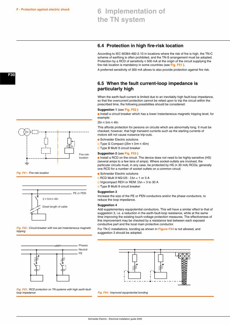
Schneider Electric - Electrical installation guide 2005
F30
F - Protection against electric shock
6.4 Protection in high fire-risk location
According to IEC 60364-482-2.10 in locations where the risk of fire is high, the TN-Cscheme of earthing is often prohibited, and the TN-S arrangement must be adopted.Protection by a RCD of sensitivity i 500 mA at the origin of the circuit supplying thefire-risk location is mandatory in some countries (see Fig. F51 ).
A preferred sensitivity of 300 mA allows to also provide protection against fire risk.
6.5 When the fault current-loop impedance isparticularly high
When the earth-fault current is limited due to an inevitably high fault-loop impedance,so that the overcurrent protection cannot be relied upon to trip the circuit within theprescribed time, the following possibilities should be considered:
Suggestion 1 (see Fig. F52 )c Install a circuit breaker which has a lower instantaneous magnetic tripping level, forexample:
2In i Irm i 4In
This affords protection for persons on circuits which are abnormally long. It must bechecked, however, that high transient currents such as the starting currents ofmotors will not cause nuisance trip-outs.
c Schneider Electric solutionsv Type G Compact (2Im i Irm i 4Im)v Type B Multi 9 circuit breaker
Suggestion 2 (see Fig. F53 )c Install a RCD on the circuit. The device does not need to be highly-sensitive (HS)(several amps to a few tens of amps). Where socket-outlets are involved, theparticular circuits must, in any case, be protected by HS (i 30 mA) RCDs; generallyone RCD for a number of socket outlets on a common circuit.
c Schneider Electric solutionsv RCD Multi 9 NG125 : I∆n = 1 or 3 Av Vigicompact REH or REM: I∆n = 3 to 30 Av Type B Multi 9 circuit breaker
Suggestion 3Increase the size of the PE or PEN conductors and/or the phase conductors, toreduce the loop impedance.
Suggestion 4Add supplementary equipotential conductors. This will have a similar effect to that ofsuggestion 3, i.e. a reduction in the earth-fault-loop resistance, while at the sametime improving the existing touch-voltage protection measures. The effectiveness ofthis improvement may be checked by a resistance test between each exposedconductive part and the local main protective conductor.
For TN-C installations, bonding as shown in Figure F54 is not allowed, andsuggestion 3 should be adopted.
Fig. F51 : Fire-risk location
Fire-risklocation
Fig. F52 : Circuit-breaker with low-set instantaneous magnetictripping
2 i Irm i 4In
PE or PEN
Great length of cable
Fig. F53 : RCD protection on TN systems with high earth-fault-loop impedance Fig. F54 : Improved equipotential bonding
Phases
NeutralPE
6 Implementation ofthe TN system
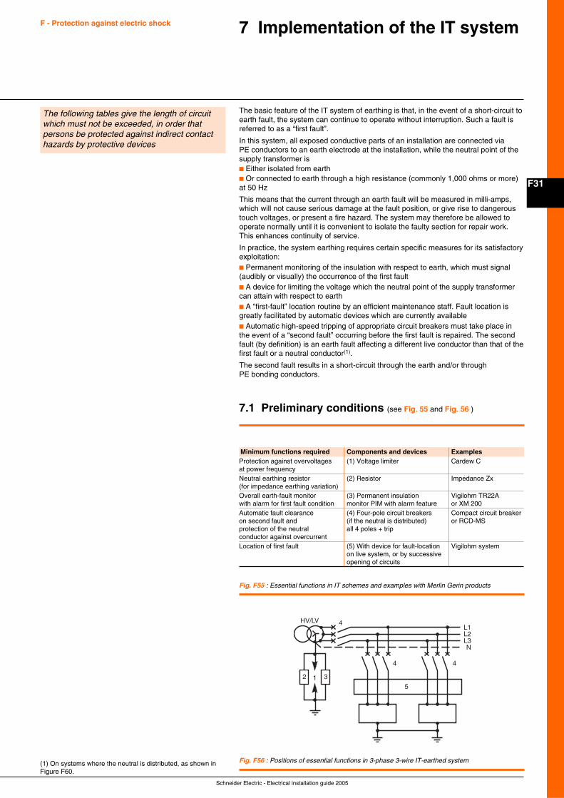
F31
Schneider Electric - Electrical installation guide 2005
F - Protection against electric shock 7 Implementation of the IT system
The basic feature of the IT system of earthing is that, in the event of a short-circuit toearth fault, the system can continue to operate without interruption. Such a fault isreferred to as a “first fault”.
In this system, all exposed conductive parts of an installation are connected viaPE conductors to an earth electrode at the installation, while the neutral point of thesupply transformer isc Either isolated from earthc Or connected to earth through a high resistance (commonly 1,000 ohms or more)at 50 Hz
This means that the current through an earth fault will be measured in milli-amps,which will not cause serious damage at the fault position, or give rise to dangeroustouch voltages, or present a fire hazard. The system may therefore be allowed tooperate normally until it is convenient to isolate the faulty section for repair work.This enhances continuity of service.
In practice, the system earthing requires certain specific measures for its satisfactoryexploitation:c Permanent monitoring of the insulation with respect to earth, which must signal(audibly or visually) the occurrence of the first faultc A device for limiting the voltage which the neutral point of the supply transformercan attain with respect to earthc A “first-fault” location routine by an efficient maintenance staff. Fault location isgreatly facilitated by automatic devices which are currently availablec Automatic high-speed tripping of appropriate circuit breakers must take place inthe event of a “second fault” occurring before the first fault is repaired. The secondfault (by definition) is an earth fault affecting a different live conductor than that of thefirst fault or a neutral conductor(1).
The second fault results in a short-circuit through the earth and/or throughPE bonding conductors.
7.1 Preliminary conditions (see Fig. 55 and Fig. 56 )
(1) On systems where the neutral is distributed, as shown inFigure F60.
The following tables give the length of circuitwhich must not be exceeded, in order thatpersons be protected against indirect contacthazards by protective devices
Minimum functions required Components and devices ExamplesProtection against overvoltages (1) Voltage limiter Cardew Cat power frequencyNeutral earthing resistor (2) Resistor Impedance Zx(for impedance earthing variation)Overall earth-fault monitor (3) Permanent insulation Vigilohm TR22Awith alarm for first fault condition monitor PIM with alarm feature or XM 200Automatic fault clearance (4) Four-pole circuit breakers Compact circuit breakeron second fault and (if the neutral is distributed) or RCD-MSprotection of the neutral all 4 poles + tripconductor against overcurrentLocation of first fault (5) With device for fault-location Vigilohm system
on live system, or by successiveopening of circuits
Fig. F55 : Essential functions in IT schemes and examples with Merlin Gerin products
Fig. F56 : Positions of essential functions in 3-phase 3-wire IT-earthed system
L1L2L3N
HV/LV
4
4
2 1 3
5
4
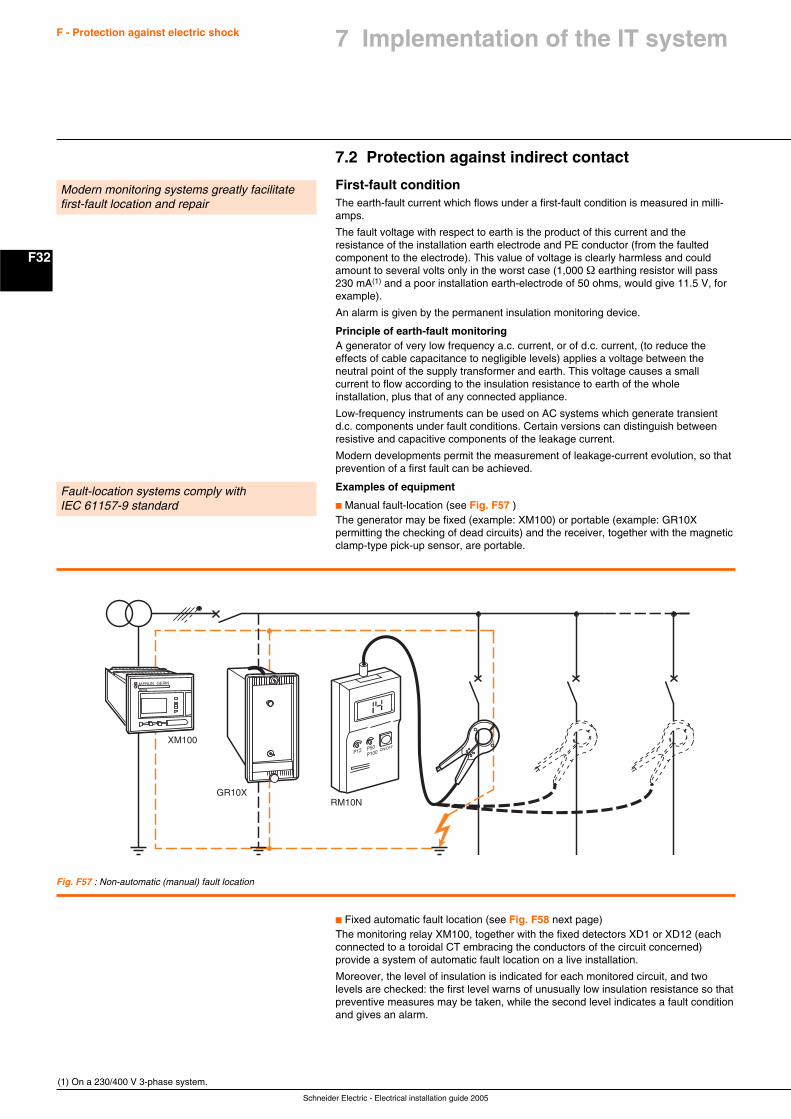
Schneider Electric - Electrical installation guide 2005
F32
F - Protection against electric shock
7.2 Protection against indirect contact
First-fault conditionThe earth-fault current which flows under a first-fault condition is measured in milli-amps.
The fault voltage with respect to earth is the product of this current and theresistance of the installation earth electrode and PE conductor (from the faultedcomponent to the electrode). This value of voltage is clearly harmless and couldamount to several volts only in the worst case (1,000 Ω earthing resistor will pass230 mA(1) and a poor installation earth-electrode of 50 ohms, would give 11.5 V, forexample).
An alarm is given by the permanent insulation monitoring device.
Principle of earth-fault monitoringA generator of very low frequency a.c. current, or of d.c. current, (to reduce theeffects of cable capacitance to negligible levels) applies a voltage between theneutral point of the supply transformer and earth. This voltage causes a smallcurrent to flow according to the insulation resistance to earth of the wholeinstallation, plus that of any connected appliance.
Low-frequency instruments can be used on AC systems which generate transientd.c. components under fault conditions. Certain versions can distinguish betweenresistive and capacitive components of the leakage current.
Modern developments permit the measurement of leakage-current evolution, so thatprevention of a first fault can be achieved.
Examples of equipment
c Manual fault-location (see Fig. F57 )The generator may be fixed (example: XM100) or portable (example: GR10Xpermitting the checking of dead circuits) and the receiver, together with the magneticclamp-type pick-up sensor, are portable.
Modern monitoring systems greatly facilitatefirst-fault location and repair
(1) On a 230/400 V 3-phase system.
Fault-location systems comply withIEC 61157-9 standard
Fig. F57 : Non-automatic (manual) fault location
P12 P50P100 ON/OFF
GR10XRM10N
XM100
MERLIN GERIN
XM100
c Fixed automatic fault location (see Fig. F58 next page)The monitoring relay XM100, together with the fixed detectors XD1 or XD12 (eachconnected to a toroidal CT embracing the conductors of the circuit concerned)provide a system of automatic fault location on a live installation.
Moreover, the level of insulation is indicated for each monitored circuit, and twolevels are checked: the first level warns of unusually low insulation resistance so thatpreventive measures may be taken, while the second level indicates a fault conditionand gives an alarm.
7 Implementation of the IT system
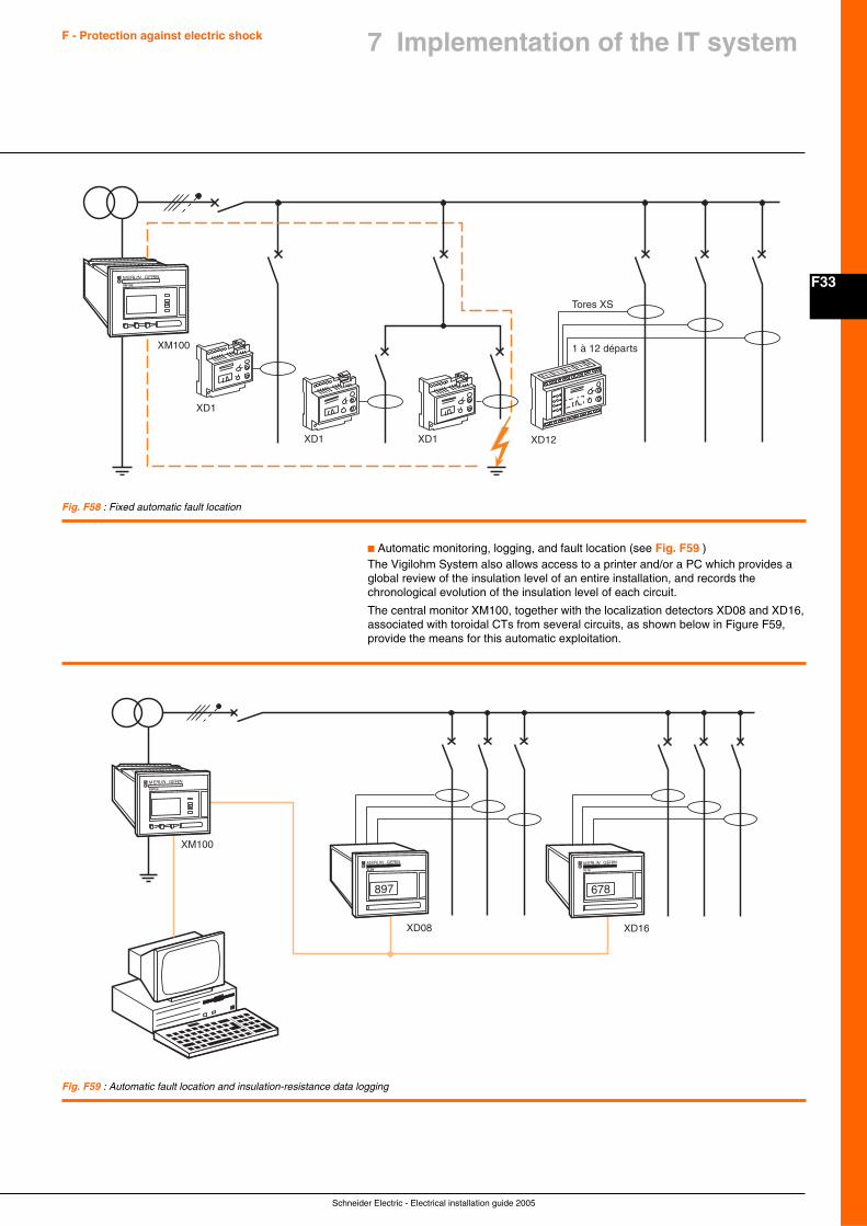
F33
Schneider Electric - Electrical installation guide 2005
F - Protection against electric shock 7 Implementation of the IT system
Fig. F58 : Fixed automatic fault location
Fig. F59 : Automatic fault location and insulation-resistance data logging
XD1
XD1 XD1 XD12
1 à 12 départs
Tores XS
XM100
MERLIN GERIN
XM100
c Automatic monitoring, logging, and fault location (see Fig. F59 )The Vigilohm System also allows access to a printer and/or a PC which provides aglobal review of the insulation level of an entire installation, and records thechronological evolution of the insulation level of each circuit.
The central monitor XM100, together with the localization detectors XD08 and XD16,associated with toroidal CTs from several circuits, as shown below in Figure F59,provide the means for this automatic exploitation.
XM100
XD08 XD16
MERLIN GERIN
XM100
MERLIN GERIN
XL08
897
MERLIN GERIN
XL16
678
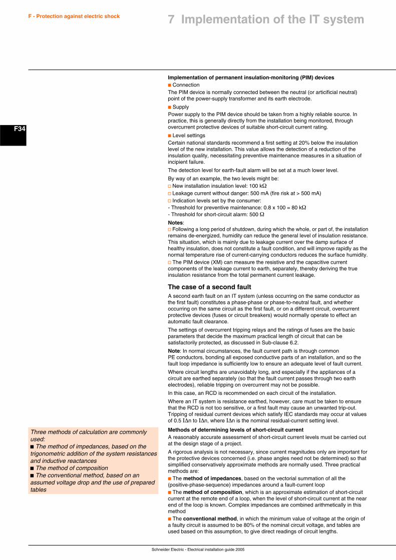
Schneider Electric - Electrical installation guide 2005
F34
F - Protection against electric shock
Implementation of permanent insulation-monitoring (PIM) devicesc ConnectionThe PIM device is normally connected between the neutral (or articificial neutral)point of the power-supply transformer and its earth electrode.
c SupplyPower supply to the PIM device should be taken from a highly reliable source. Inpractice, this is generally directly from the installation being monitored, throughovercurrent protective devices of suitable short-circuit current rating.
c Level settingsCertain national standards recommend a first setting at 20% below the insulationlevel of the new installation. This value allows the detection of a reduction of theinsulation quality, necessitating preventive maintenance measures in a situation ofincipient failure.
The detection level for earth-fault alarm will be set at a much lower level.
By way of an example, the two levels might be:v New installation insulation level: 100 kΩv Leakage current without danger: 500 mA (fire risk at > 500 mA)v Indication levels set by the consumer:- Threshold for preventive maintenance: 0.8 x 100 = 80 kΩ- Threshold for short-circuit alarm: 500 ΩNotes:v Following a long period of shutdown, during which the whole, or part of, the installationremains de-energized, humidity can reduce the general level of insulation resistance.This situation, which is mainly due to leakage current over the damp surface ofhealthy insulation, does not constitute a fault condition, and will improve rapidly as thenormal temperature rise of current-carrying conductors reduces the surface humidity.v The PIM device (XM) can measure the resistive and the capacitive currentcomponents of the leakage current to earth, separately, thereby deriving the trueinsulation resistance from the total permanent current leakage.
The case of a second faultA second earth fault on an IT system (unless occurring on the same conductor asthe first fault) constitutes a phase-phase or phase-to-neutral fault, and whetheroccurring on the same circuit as the first fault, or on a different circuit, overcurrentprotective devices (fuses or circuit breakers) would normally operate to effect anautomatic fault clearance.
The settings of overcurrent tripping relays and the ratings of fuses are the basicparameters that decide the maximum practical length of circuit that can besatisfactorily protected, as discussed in Sub-clause 6.2.
Note: In normal circumstances, the fault current path is through commonPE conductors, bonding all exposed conductive parts of an installation, and so thefault loop impedance is sufficiently low to ensure an adequate level of fault current.
Where circuit lengths are unavoidably long, and especially if the appliances of acircuit are earthed separately (so that the fault current passes through two earthelectrodes), reliable tripping on overcurrent may not be possible.
In this case, an RCD is recommended on each circuit of the installation.
Where an IT system is resistance earthed, however, care must be taken to ensurethat the RCD is not too sensitive, or a first fault may cause an unwanted trip-out.Tripping of residual current devices which satisfy IEC standards may occur at valuesof 0.5 I∆n to I∆n, where I∆n is the nominal residual-current setting level.
Methods of determining levels of short-circuit currentA reasonably accurate assessment of short-circuit current levels must be carried outat the design stage of a project.
A rigorous analysis is not necessary, since current magnitudes only are important forthe protective devices concerned (i.e. phase angles need not be determined) so thatsimplified conservatively approximate methods are normally used. Three practicalmethods are:c The method of impedances, based on the vectorial summation of all the(positive-phase-sequence) impedances around a fault-current loopc The method of composition, which is an approximate estimation of short-circuitcurrent at the remote end of a loop, when the level of short-circuit current at the nearend of the loop is known. Complex impedances are combined arithmetically in thismethodc The conventional method, in which the minimum value of voltage at the origin ofa faulty circuit is assumed to be 80% of the nominal circuit voltage, and tables areused based on this assumption, to give direct readings of circuit lengths.
Three methods of calculation are commonlyused:c The method of impedances, based on thetrigonometric addition of the system resistancesand inductive reactancesc The method of compositionc The conventional method, based on anassumed voltage drop and the use of preparedtables
7 Implementation of the IT system
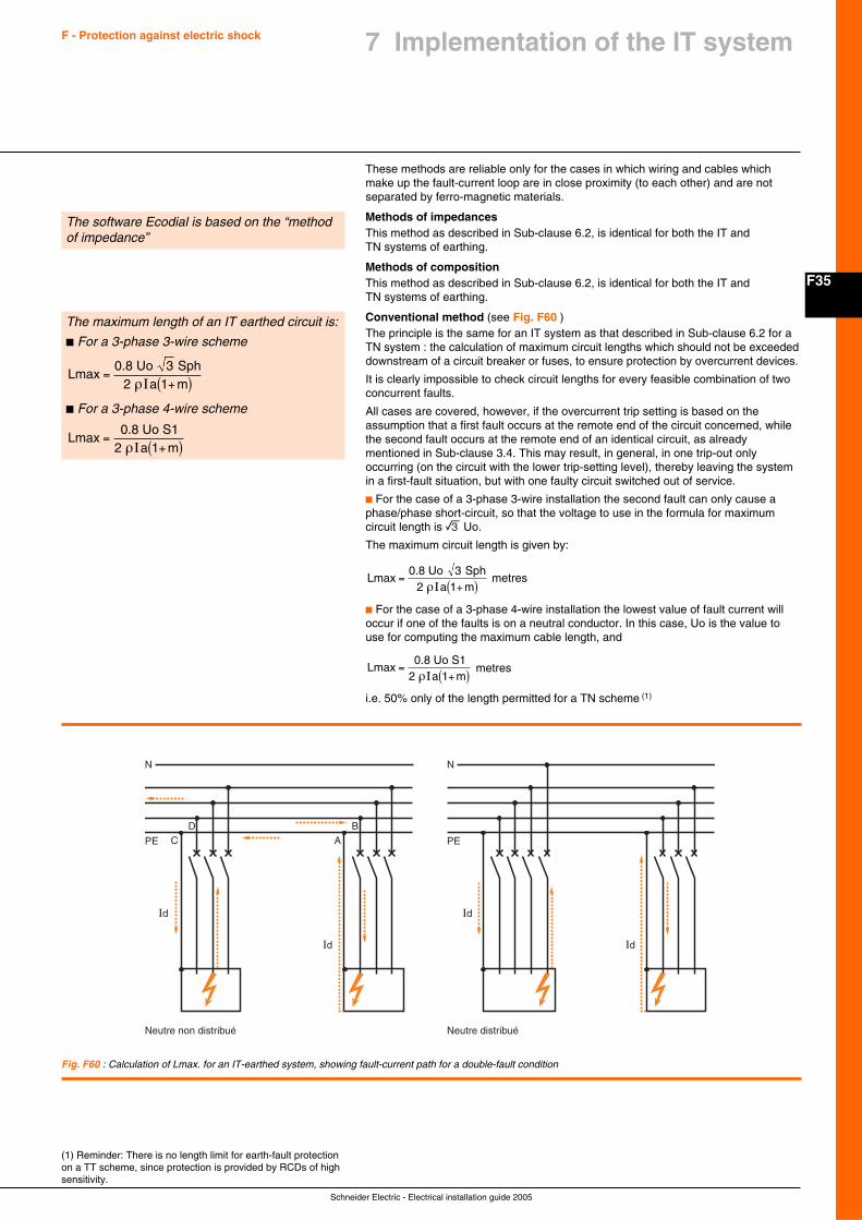
F35
Schneider Electric - Electrical installation guide 2005
F - Protection against electric shock 7 Implementation of the IT system
These methods are reliable only for the cases in which wiring and cables whichmake up the fault-current loop are in close proximity (to each other) and are notseparated by ferro-magnetic materials.
Methods of impedancesThis method as described in Sub-clause 6.2, is identical for both the IT andTN systems of earthing.
Methods of compositionThis method as described in Sub-clause 6.2, is identical for both the IT andTN systems of earthing.
Conventional method (see Fig. F60 )The principle is the same for an IT system as that described in Sub-clause 6.2 for aTN system : the calculation of maximum circuit lengths which should not be exceededdownstream of a circuit breaker or fuses, to ensure protection by overcurrent devices.
It is clearly impossible to check circuit lengths for every feasible combination of twoconcurrent faults.
All cases are covered, however, if the overcurrent trip setting is based on theassumption that a first fault occurs at the remote end of the circuit concerned, whilethe second fault occurs at the remote end of an identical circuit, as alreadymentioned in Sub-clause 3.4. This may result, in general, in one trip-out onlyoccurring (on the circuit with the lower trip-setting level), thereby leaving the systemin a first-fault situation, but with one faulty circuit switched out of service.
c For the case of a 3-phase 3-wire installation the second fault can only cause aphase/phase short-circuit, so that the voltage to use in the formula for maximumcircuit length is e Uo.
The maximum circuit length is given by:
La m
max0.8 Uo 3 Sph
2 =
+( )ρI 1 metres
c For the case of a 3-phase 4-wire installation the lowest value of fault current willoccur if one of the faults is on a neutral conductor. In this case, Uo is the value touse for computing the maximum cable length, and
La m
max0.8 Uo S1
2 =
+( )ρI 1 metres
i.e. 50% only of the length permitted for a TN scheme (1)
The software Ecodial is based on the “methodof impedance”
The maximum length of an IT earthed circuit is:
c For a 3-phase 3-wire scheme
La m
max0.8 Uo 3 Sph
2 =
+( )ρI 1
c For a 3-phase 4-wire scheme
La m
max0.8 Uo S1
2 =
+( )ρI 1
(1) Reminder: There is no length limit for earth-fault protectionon a TT scheme, since protection is provided by RCDs of highsensitivity.
Fig. F60 : Calculation of Lmax. for an IT-earthed system, showing fault-current path for a double-fault condition
Id
PE
Neutre non distribué
CD
Id
AB
N
Id
PE
Neutre distribué
Id
N
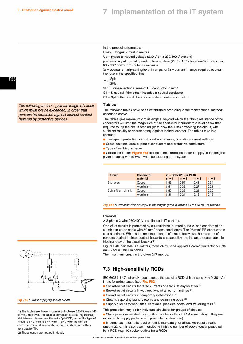
Schneider Electric - Electrical installation guide 2005
F36
F - Protection against electric shock
(1) The tables are those shown in Sub-clause 6.2 (Figures F45to F48). However, the table of correction factors (Figure F61)which takes into account the ratio Sph/SPE, and of the type ofcircuit (3-ph 3-wire; 3-ph 4-wire; 1-ph 2-wire) as well asconductor material, is specific to the IT system, and differsfrom that for TN.(2) These cases are treated in detail.
In the preceding formulae:Lmax = longest circuit in metresUo = phase-to-neutral voltage (230 V on a 230/400 V system)ρ = resistivity at normal operating temperature (22.5 x 10⁻³ ohms-mm2/m for copper,36 x 10-3 ohms-mm2/m for aluminium)Ia = overcurrent trip-setting level in amps, or Ia = current in amps required to clearthe fuse in the specified time
mSphSPE
=
SPE = cross-sectional area of PE conductor in mm2
S1 = S neutral if the circuit includes a neutral conductorS1 = Sph if the circuit does not include a neutral conductor
TablesThe following tables have been established according to the “conventional method”described above.
The tables give maximum circuit lengths, beyond which the ohmic resistance of theconductors will limit the magnitude of the short-circuit current to a level below thatrequired to trip the circuit breaker (or to blow the fuse) protecting the circuit, withsufficient rapidity to ensure safety against indirect contact. The tables take intoaccount:c The type of protection: circuit breakers or fuses, operating-current settingsc Cross-sectional area of phase conductors and protective conductorsc Type of earthing schemec Correction factor: Figure F61 indicates the correction factor to apply to the lengthsgiven in tables F44 to F47, when considering an IT system
The following tables(1) give the length of circuitwhich must not be exceeded, in order thatpersons be protected against indirect contacthazards by protective devices
Fig. F61 : Correction factor to apply to the lengths given in tables F45 to F48 for TN systems
Circuit Conductor m = Sph/SPE (or PEN)material m = 1 m = 2 m = 3 m = 4
3 phases Copper 0.86 0.57 0.43 0.34Aluminium 0.54 0.36 0.27 0.21
3ph + N or 1ph + N Copper 0.50 0.33 0.25 0.20Aluminium 0.31 0.21 0.16 0.12
ExampleA 3-phase 3-wire 230/400 V installation is IT-earthed.
One of its circuits is protected by a circuit breaker rated at 63 A, and consists of analuminium-cored cable with 50 mm2 phase conductors. The 25 mm2 PE conductor isalso aluminum. What is the maximum length of circuit, below which protection ofpersons against indirect-contact hazards is assured by the instantaneous magnetictripping relay of the circuit breaker?Figure F46 indicates 603 metres, to which must be applied a correction factor of 0.36(m = 2 for aluminium cable).The maximum length is therefore 217 metres.
7.3 High-sensitivity RCDs
IEC 60364-4-471 strongly recommends the use of a RCD of high sensitivity (i 30 mA)in the following cases (see Fig. F62 ):c Socket-outlet circuits for rated currents of i 32 A at any location(2)
c Socket-outlet circuits in wet locations at all current ratings (2)
c Socket-outlet circuits in temporary installations (2)
c Circuits supplying laundry rooms and swimming pools (2)
c Supply circuits to work-sites, caravans, pleasure boats, and travelling fairs (2)
This protection may be for individual circuits or for groups of circuits:c Strongly recommended for circuits of socket outlets u 20 A (mandatory if they areexpected to supply portable equipment for outdoor use)c In some countries, this requirement is mandatory for all socket-outlet circuitsrated i 32 A. It is also recommended to limit the number of socket-outlet protectedby a RCD (e.g. 10 socket-outlets for a RCD)
Fig. F62 : Circuit supplying socket-outlets
7 Implementation of the IT system
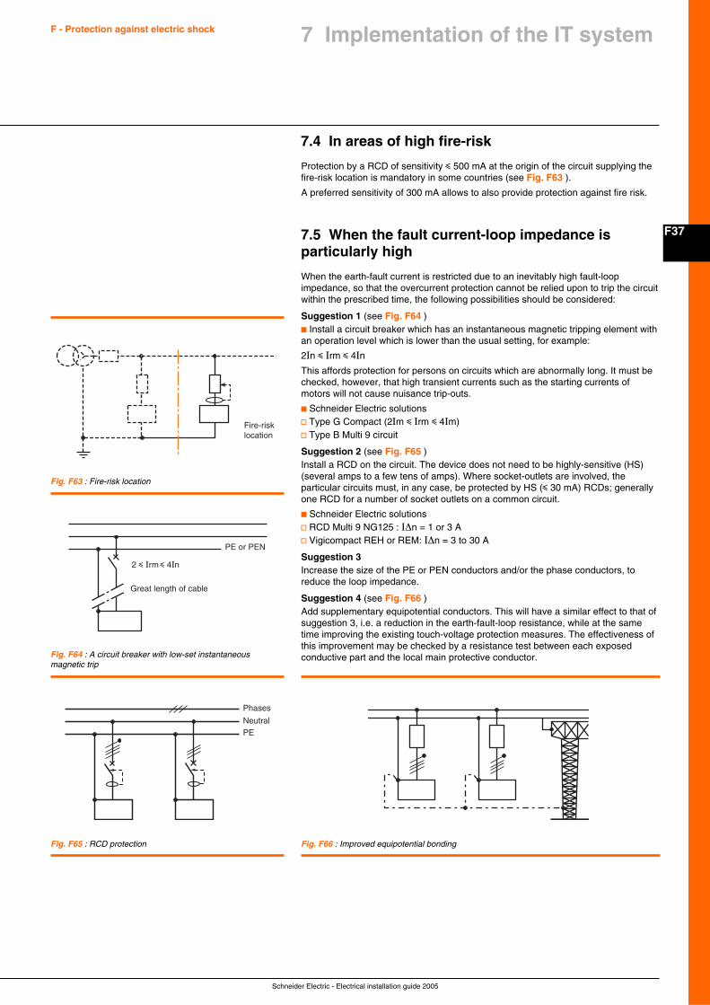
F37
Schneider Electric - Electrical installation guide 2005
F - Protection against electric shock 7 Implementation of the IT system
7.4 In areas of high fire-risk
Protection by a RCD of sensitivity i 500 mA at the origin of the circuit supplying thefire-risk location is mandatory in some countries (see Fig. F63 ).
A preferred sensitivity of 300 mA allows to also provide protection against fire risk.
7.5 When the fault current-loop impedance isparticularly high
When the earth-fault current is restricted due to an inevitably high fault-loopimpedance, so that the overcurrent protection cannot be relied upon to trip the circuitwithin the prescribed time, the following possibilities should be considered:
Suggestion 1 (see Fig. F64 )c Install a circuit breaker which has an instantaneous magnetic tripping element withan operation level which is lower than the usual setting, for example:
2In i Irm i 4In
This affords protection for persons on circuits which are abnormally long. It must bechecked, however, that high transient currents such as the starting currents ofmotors will not cause nuisance trip-outs.
c Schneider Electric solutionsv Type G Compact (2Im i Irm i 4Im)v Type B Multi 9 circuit
Suggestion 2 (see Fig. F65 )Install a RCD on the circuit. The device does not need to be highly-sensitive (HS)(several amps to a few tens of amps). Where socket-outlets are involved, theparticular circuits must, in any case, be protected by HS (i 30 mA) RCDs; generallyone RCD for a number of socket outlets on a common circuit.
c Schneider Electric solutionsv RCD Multi 9 NG125 : I∆n = 1 or 3 Av Vigicompact REH or REM: I∆n = 3 to 30 A
Suggestion 3Increase the size of the PE or PEN conductors and/or the phase conductors, toreduce the loop impedance.
Suggestion 4 (see Fig. F66 )Add supplementary equipotential conductors. This will have a similar effect to that ofsuggestion 3, i.e. a reduction in the earth-fault-loop resistance, while at the sametime improving the existing touch-voltage protection measures. The effectiveness ofthis improvement may be checked by a resistance test between each exposedconductive part and the local main protective conductor.
Fig. F63 : Fire-risk location
Fig. F64 : A circuit breaker with low-set instantaneousmagnetic trip
Fig. F65 : RCD protection Fig. F66 : Improved equipotential bonding
Phases
NeutralPE
2 i Irm i 4In
PE or PEN
Great length of cable
Fire-risklocation
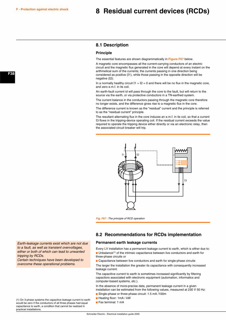
Schneider Electric - Electrical installation guide 2005
F38
F - Protection against electric shock 8 Residual current devices (RCDs)
8.1 Description
Principle
The essential features are shown diagrammatically in Figure F67 below.
A magnetic core encompasses all the current-carrying conductors of an electriccircuit and the magnetic flux generated in the core will depend at every instant on thearithmetical sum of the currents; the currents passing in one direction beingconsidered as positive (I1), while those passing in the opposite direction will benegative (I2).
In a normally healthy circuit I1 + I2 = 0 and there will be no flux in the magnetic core,and zero e.m.f. in its coil.
An earth-fault current id will pass through the core to the fault, but will return to thesource via the earth, or via protective conductors in a TN-earthed system.
The current balance in the conductors passing through the magnetic core thereforeno longer exists, and the difference gives rise to a magnetic flux in the core.
The difference current is known as the “residual” current and the principle is referredto as the “residual current” principle.
The resultant alternating flux in the core induces an e.m.f. in its coil, so that a currentI3 flows in the tripping-device operating coil. If the residual current exceeds the valuerequired to operate the tripping device either directly or via an electronic relay, thenthe associated circuit breaker will trip.
Fig. F67 : The principle of RCD operation
I1 I2
I3
8.2 Recommendations for RCDs implementation
Permanent earth leakage currents
Every LV installation has a permanent leakage current to earth, which is either due to:c Unbalance(1) of the intrinsic capacitance between live conductors and earth forthree-phase circuits orc Capacitance between live conductors and earth for single-phase circuits
The larger the installation the greater its capacitance with consequently increasedleakage current.
The capacitive current to earth is sometimes increased significantly by filteringcapacitors associated with electronic equipment (automation, informatics andcomputer-based systems, etc.).
In the absence of more-precise data, permanent leakage current in a giveninstallation can be estimated from the following values, measured at 230 V 50 Hz:c Single-phase or three-phase circuit: 1.5 mA /100mc Heating floor: 1mA / kWc Fax terminal: 1 mA
Earth-leakage currents exist which are not dueto a fault, as well as transient overvoltages,either or both of which can lead to unwantedtripping by RCDs.Certain techniques have been developed toovercome these operational problems.
(1) On 3-phase systems the capacitive leakage current to earthwould be zero if the conductors of all three phases had equalcapacitance to earth, a condition that cannot be realized inpractical installations.
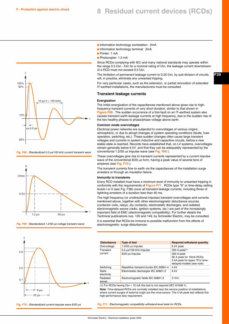
F39
Schneider Electric - Electrical installation guide 2005
F - Protection against electric shock
c Information technology workstation: 2mAc Information technology terminal: 2mAc Printer: 1 mAc Photocopier: 1.5 mA
Since RCDs complying with IEC and many national standards may operate withinthe range 0.5 I∆n - I∆n for a nominal rating of I∆n, the leakage current downstreamof a RCD must not exceed 0.5 I∆n.
The limitation of permanent leakage current to 0.25 I∆n, by sub-division of circuits,will, in practice, eliminate any unwanted tripping.
For very particular cases, such as the extension, or partial renovation of extendedIT-earthed installations, the manufacturers must be consulted.
Transient leakage currents
EnergizationThe initial energization of the capacitances mentioned above gives rise to high-frequency transient currents of very short duration, similar to that shown inFigure F68 . The sudden occurrence of a first-fault on an IT-earthed system alsocauses transient earth-leakage currents at high frequency, due to the sudden rise ofthe two healthy phases to phase/phase voltage above earth.
Common mode overvoltagesElectrical power networks are subjected to overvoltages of various origins;atmospheric, or due to abrupt changes of system operating conditions (faults, fuseoperation, switching, etc.). These sudden changes often cause large transientvoltages and currents in system inductive and capacitive circuits, before a newstable state is reached. Records have established that, on LV systems, overvoltagesremain generally below 6 kV, and that they can be adequately represented by theconventional 1.2/50 µs impulse wave (see Fig. F69 ).
These overvoltages give rise to transient currents represented by a current impulsewave of the conventional 8/20 µs form, having a peak value of several tens ofamperes (see Fig. F70 ).
The transient currents flow to earth via the capacitances of the installation surgearresters or through an insulation failure.
Immunity to transientsEvery RCD installed must have a minimum level of immunity to unwanted tripping inconformity with the requirements of Figure F71 . RCDs type “S” or time-delay settinglevels I or II (see Fig. F38) cover all transient leakage currents, including those oflightning arresters of a duration less than 40 ms.
The high-frequency (or unidirectional impulse) transient overvoltages and currentsmentioned above, together with other electromagnetic disturbance sources(contactor coils, relays, dry contacts), electrostatic discharges, and radiatedelectromagnetic waves (radio, ignition systems, etc.) are part of the increasinglyimportant field of EMC (electromagnetic compatibility). For further details theTechnical publications nos. 120 and 149, by Schneider Electric, may be consulted.
It is essential that RCDs be immune to possible malfunction from the effects ofelectromagnetic- surge disturbances.
10 s (f = 100 kHz)
t
100%
I
90%
10%
ca.0.5 s
60%
t1.2 s 50 s
0.5U
U
Umax
Fig. F68 : Standardized 0.5 µs/100 kHz current transient wave
Fig. F69 : Standardized 1.2/50 µs voltage transient wave
t
0.5
0.9
0.1
I
Fig. F70 : Standardized current-impulse wave 8/20 µs
Disturbance Type of test Required withstand quantityOvervoltage 1.2/50 µs impulse 6 kV peakTransient 0.5 µs/100 kHz impulse 200 A peak(1)
current 8/20 µs impulse 200 A peak60 A peak for 10mA RCDs5 kA peak for types “S”or time-delayed models (see note)
Switching Repetitive transient bursts IEC 60801-4 4 kVStatic Electrostatic discharges IEC 60801-2 8 kVelectricityRadiated Electromagnetic fields IEC 60801-3 3 V/mwaves
(1) For RCDs having I∆n < 10 mA this test is not required (IEC 61008-1).
Note: Time-delayed RCDs are normally installed near the service position of installations,where current surges of external origin are the most severe. The 5 kA peak test reflects thishigh-performance duty requirement.
Fig. F71 : Electromagnetic compatibility withstand-level tests for RCDs
8 Residual current devices (RCDs)
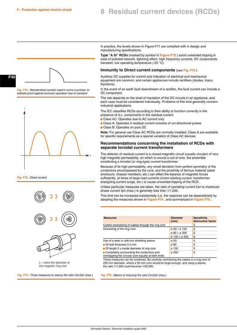
Schneider Electric - Electrical installation guide 2005
F40
F - Protection against electric shock
In practice, the levels shown in Figure F71 are complied with in design andmanufacturing specifications.
Type “A Si” RCDs (marked by symbol in Figure F72 ) avoid unwanted tripping incase of polluted network, lightning effect, high frequency currents, DC components,transient, low operating temperature (-25 °C).
Immunity to Direct current components (see Fig. F73 )
Auxiliary DC supplies for control and indication of electrical and mechanicalequipment are common, and certain appliances include rectifiers (diodes, triacs,thyristors).
In the event of an earth fault downstream of a rectifier, the fault current can include aDC component.
The risk depends on the level of insulation of the DC circuits in an appliance, andeach case must be considered individually. Problems of this kind generally concernindustrial applications.
The IEC classifies RCDs according to their ability to function correctly in thepresence of d.c. components in the residual current.c Class AC: Operates due to AC current onlyc Class A: Operates if residual current consists of uni-directional pulsesc Class B: Operates on pure DC
Note: For general use Class AC RCDs are normally installed. Class A are availablefor specific requirements as a special variation of Class AC devices.
Recommendations concerning the installation of RCDs withseparate toroidal current transformers
The detector of residual current is a closed magnetic circuit (usually circular) of veryhigh magnetic permeability, on which is wound a coil of wire, the ensembleconstituting a toroidal (or ring-type) current transformer.
Because of its high permeability, any small deviation from perfect symmetry of theconductors encompassed by the core, and the proximity of ferrous material (steelenclosure, chassis members, etc.) can affect the balance of magnetic forcessufficiently, at times of large load currents (motor-starting current, transformerenergizing current surge, etc.) to cause unwanted tripping of the RCD.
Unless particular measures are taken, the ratio of operating current I∆n to maximumphase current Iph (max.) is generally less than 1/1,000.
This limit can be increased substantially (i.e. the response can be desensitized) byadopting the measures shown in Figure F74 , and summarized in Figure F75 .
Fig. F72 : Standardized symbol used in some countries, toindicate proof against incorrect operation due to transient
Fig. F73 : Direct current
t
i
Fig. F74 : Three measures to reduce the ratio I∆n/Iph (max.)
L
L = twice the diameter of the magnetic ring core
Fig. F75 : Means of reducing the ratio I∆n/Iph (max.)
Measures Diameter Sensitivity(mm) diminution factor
Careful centralizing of cables through the ring core 3Oversizing of the ring core ø 50 > ø 100 2
ø 80 > ø 200 2ø 120 > ø 200 6
Use of a steel or soft-iron shielding sleeve ø 50 4c Of wall thickness 0.5 mm ø 80 3c Of length 2 x inside diameter of ring core ø 120 3c Completely surrounding the conductors and ø 200 2overlapping the circular core equally at both endsThese measures can be combined. By carefully centralizing the cables in a ring core of200 mm diameter, where a 50 mm core would be large enough, and using a sleeve,the ratio 1/1,000 could become 1/30,000.
8 Residual current devices (RCDs)
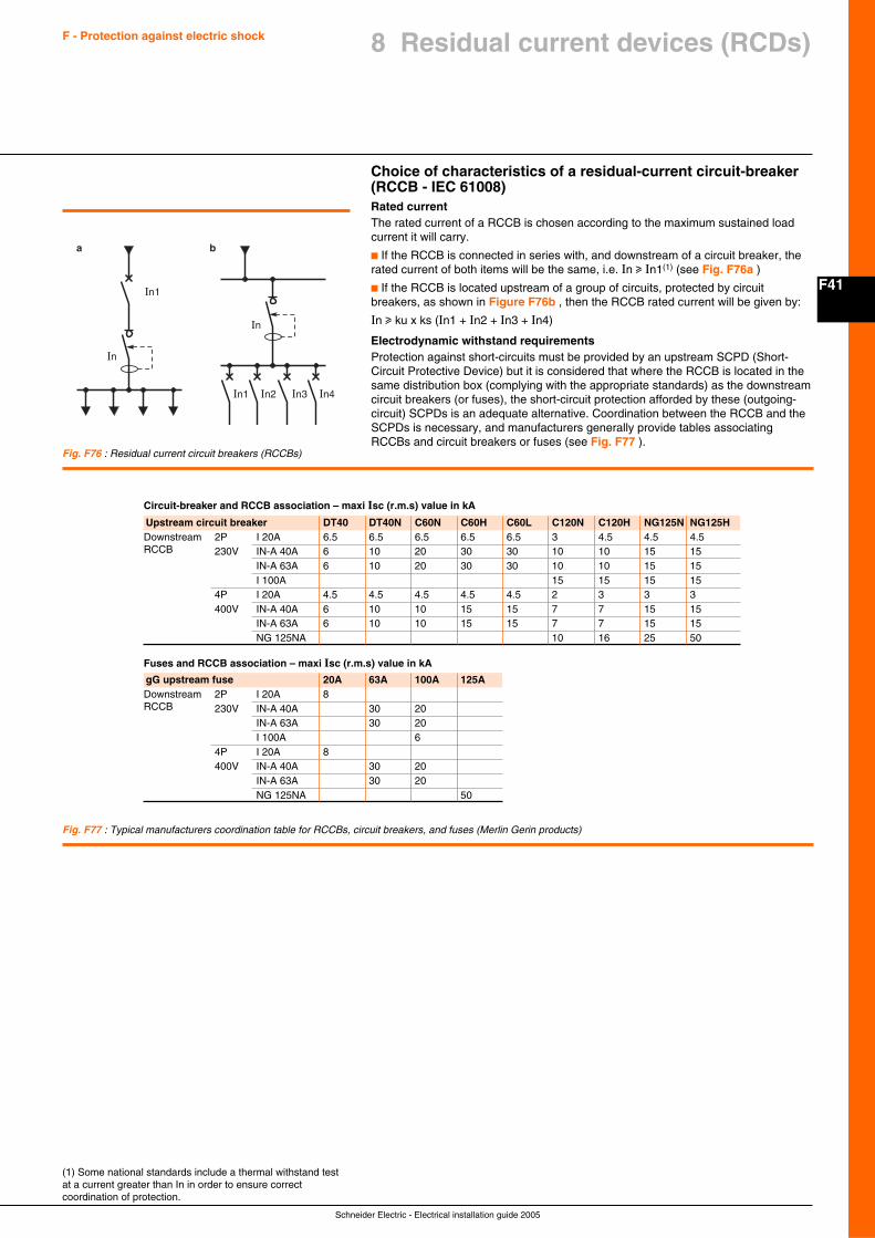
F41
Schneider Electric - Electrical installation guide 2005
F - Protection against electric shock 8 Residual current devices (RCDs)
Choice of characteristics of a residual-current circuit-breaker(RCCB - IEC 61008)Rated currentThe rated current of a RCCB is chosen according to the maximum sustained loadcurrent it will carry.
c If the RCCB is connected in series with, and downstream of a circuit breaker, therated current of both items will be the same, i.e. In u In1(1) (see Fig. F76a )
c If the RCCB is located upstream of a group of circuits, protected by circuitbreakers, as shown in Figure F76b , then the RCCB rated current will be given by:
In u ku x ks (In1 + In2 + In3 + In4)
Electrodynamic withstand requirementsProtection against short-circuits must be provided by an upstream SCPD (Short-Circuit Protective Device) but it is considered that where the RCCB is located in thesame distribution box (complying with the appropriate standards) as the downstreamcircuit breakers (or fuses), the short-circuit protection afforded by these (outgoing-circuit) SCPDs is an adequate alternative. Coordination between the RCCB and theSCPDs is necessary, and manufacturers generally provide tables associatingRCCBs and circuit breakers or fuses (see Fig. F77 ).
(1) Some national standards include a thermal withstand testat a current greater than In in order to ensure correctcoordination of protection.
Fig. F76 : Residual current circuit breakers (RCCBs)
Upstream circuit breaker DT40 DT40N C60N C60H C60L C120N C120H NG125N NG125HDownstream 2P I 20A 6.5 6.5 6.5 6.5 6.5 3 4.5 4.5 4.5RCCB 230V IN-A 40A 6 10 20 30 30 10 10 15 15
IN-A 63A 6 10 20 30 30 10 10 15 15I 100A 15 15 15 15
4P I 20A 4.5 4.5 4.5 4.5 4.5 2 3 3 3400V IN-A 40A 6 10 10 15 15 7 7 15 15
IN-A 63A 6 10 10 15 15 7 7 15 15NG 125NA 10 16 25 50
Circuit-breaker and RCCB association – maxi Isc (r.m.s) value in kA
Fuses and RCCB association – maxi Isc (r.m.s) value in kA
gG upstream fuse 20A 63A 100A 125ADownstream 2P I 20A 8RCCB 230V IN-A 40A 30 20
IN-A 63A 30 20I 100A 6
4P I 20A 8400V IN-A 40A 30 20
IN-A 63A 30 20NG 125NA 50
Fig. F77 : Typical manufacturers coordination table for RCCBs, circuit breakers, and fuses (Merlin Gerin products)
In1
In1 In2 In3 In4
In
In
a b
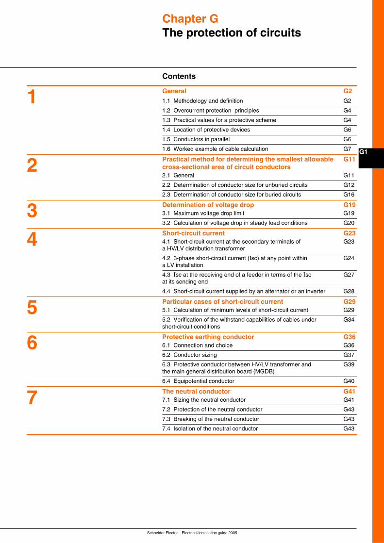
Schneider Electric - Electrical installation guide 2005
G1
Chapter GThe protection of circuits
Contents
General G2
1.1 Methodology and definition G2
1.2 Overcurrent protection principles G4
1.3 Practical values for a protective scheme G4
1.4 Location of protective devices G6
1.5 Conductors in parallel G6
1.6 Worked example of cable calculation G7
Practical method for determining the smallest allowable G11cross-sectional area of circuit conductors2.1 General G11
2.2 Determination of conductor size for unburied circuits G12
2.3 Determination of conductor size for buried circuits G16
Determination of voltage drop G193.1 Maximum voltage drop limit G19
3.2 Calculation of voltage drop in steady load conditions G20
Short-circuit current G234.1 Short-circuit current at the secondary terminals of G23a HV/LV distribution transformer
4.2 3-phase short-circuit current (Isc) at any point within G24a LV installation
4.3 Isc at the receiving end of a feeder in terms of the Isc G27at its sending end
4.4 Short-circuit current supplied by an alternator or an inverter G28
Particular cases of short-circuit current G295.1 Calculation of minimum levels of short-circuit current G29
5.2 Verification of the withstand capabilities of cables under G34short-circuit conditions
Protective earthing conductor G366.1 Connection and choice G36
6.2 Conductor sizing G37
6.3 Protective conductor between HV/LV transformer and G39the main general distribution board (MGDB)
6.4 Equipotential conductor G40
The neutral conductor G417.1 Sizing the neutral conductor G41
7.2 Protection of the neutral conductor G43
7.3 Breaking of the neutral conductor G43
7.4 Isolation of the neutral conductor G43
1
2
34
5
6
7
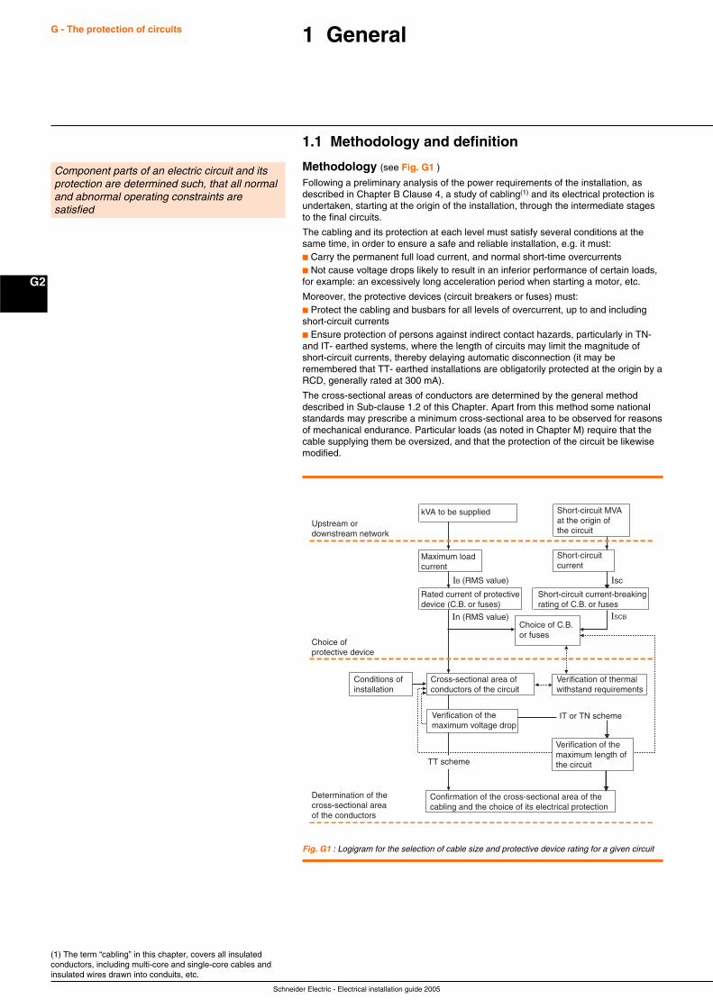
Schneider Electric - Electrical installation guide 2005
G2
G - The protection of circuits 1 General
1.1 Methodology and definition
Methodology (see Fig. G1 )
Following a preliminary analysis of the power requirements of the installation, asdescribed in Chapter B Clause 4, a study of cabling(1) and its electrical protection isundertaken, starting at the origin of the installation, through the intermediate stagesto the final circuits.
The cabling and its protection at each level must satisfy several conditions at thesame time, in order to ensure a safe and reliable installation, e.g. it must:c Carry the permanent full load current, and normal short-time overcurrentsc Not cause voltage drops likely to result in an inferior performance of certain loads,for example: an excessively long acceleration period when starting a motor, etc.
Moreover, the protective devices (circuit breakers or fuses) must:c Protect the cabling and busbars for all levels of overcurrent, up to and includingshort-circuit currentsc Ensure protection of persons against indirect contact hazards, particularly in TN-and IT- earthed systems, where the length of circuits may limit the magnitude ofshort-circuit currents, thereby delaying automatic disconnection (it may beremembered that TT- earthed installations are obligatorily protected at the origin by aRCD, generally rated at 300 mA).
The cross-sectional areas of conductors are determined by the general methoddescribed in Sub-clause 1.2 of this Chapter. Apart from this method some nationalstandards may prescribe a minimum cross-sectional area to be observed for reasonsof mechanical endurance. Particular loads (as noted in Chapter M) require that thecable supplying them be oversized, and that the protection of the circuit be likewisemodified.
Fig. G1 : Logigram for the selection of cable size and protective device rating for a given circuit
(1) The term “cabling” in this chapter, covers all insulatedconductors, including multi-core and single-core cables andinsulated wires drawn into conduits, etc.
Upstream ordownstream network
kVA to be supplied
Maximum loadcurrent
Short-circuit MVAat the origin ofthe circuit
Choice of C.B.or fuses
IT or TN scheme
Short-circuit current
Isc
In (RMS value)
IB (RMS value)
ISCB
Conditions ofinstallation
Cross-sectional area ofconductors of the circuit
Verification of thermalwithstand requirements
Rated current of protectivedevice (C.B. or fuses)
Short-circuit current-breakingrating of C.B. or fuses
Choice ofprotective device
Determination of thecross-sectional areaof the conductors
Verification of themaximum voltage drop
Confirmation of the cross-sectional area of thecabling and the choice of its electrical protection
Verification of themaximum length ofthe circuitTT scheme
Component parts of an electric circuit and itsprotection are determined such, that all normaland abnormal operating constraints aresatisfied
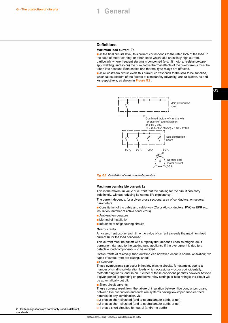
Schneider Electric - Electrical installation guide 2005
G3
G - The protection of circuits
Fig. G2 : Calculation of maximum load current IB
DefinitionsMaximum load current: IBc At the final circuits level, this current corresponds to the rated kVA of the load. Inthe case of motor-starting, or other loads which take an initially-high current,particularly where frequent starting is concerned (e.g. lift motors, resistance-typespot welding, and so on) the cumulative thermal effects of the overcurrents must betaken into account. Both cables and thermal type relays are affected.c At all upstream circuit levels this current corresponds to the kVA to be supplied,which takes account of the factors of simultaneity (diversity) and utilization, ks andku respectively, as shown in Figure G2 .
(1) Both designations are commonly used in differentstandards.
Main distributionboard
Sub-distributionboard
80 A 60 A 100 A
MNormal load motor current 50 A
Combined factors of simultaneity(or diversity) and utilization:ks x ku = 0.69IB = (80+60+100+50) x 0.69 = 200 A
50 A
Maximum permissible current: IzThis is the maximum value of current that the cabling for the circuit can carryindefinitely, without reducing its normal life expectancy.
The current depends, for a given cross sectional area of conductors, on severalparameters:c Constitution of the cable and cable-way (Cu or Alu conductors; PVC or EPR etc.insulation; number of active conductors)c Ambient temperaturec Method of installationc Influence of neighbouring circuits
OvercurrentsAn overcurrent occurs each time the value of current exceeds the maximum loadcurrent IB for the load concerned.
This current must be cut off with a rapidity that depends upon its magnitude, ifpermanent damage to the cabling (and appliance if the overcurrent is due to adefective load component) is to be avoided.
Overcurrents of relatively short duration can however, occur in normal operation; twotypes of overcurrent are distinguished:c OverloadsThese overcurrents can occur in healthy electric circuits, for example, due to anumber of small short-duration loads which occasionally occur co-incidentally;motorstarting loads, and so on. If either of these conditions persists however beyonda given period (depending on protective-relay settings or fuse ratings) the circuit willbe automatically cut off.c Short-circuit currentsThese currents result from the failure of insulation between live conductors or/andbetween live conductors and earth (on systems having low-impedance-earthedneutrals) in any combination, viz:v 3 phases short-circuited (and to neutral and/or earth, or not)v 2 phases short-circuited (and to neutral and/or earth, or not)v 1 phase short-circuited to neutral (and/or to earth)
1 General
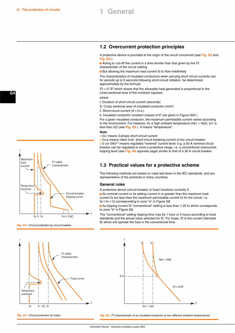
Schneider Electric - Electrical installation guide 2005
G4
G - The protection of circuits
1.2 Overcurrent protection principles
A protective device is provided at the origin of the circuit concerned (see Fig. G3 andFig. G4 ).c Acting to cut-off the current in a time shorter than that given by the I2tcharacteristic of the circuit cablingc But allowing the maximum load current IB to flow indefinitely
The characteristics of insulated conductors when carrying short-circuit currents can,for periods up to 5 seconds following short-circuit initiation, be determinedapproximately by the formula:
I2t = k2 S2 which shows that the allowable heat generated is proportional to thecross-sectional-area of the condutor squared.
wheret: Duration of short-circuit current (seconds)S: Cross sectional area of insulated conductor (mm2)I: Short-circuit current (A r.m.s.)k: Insulated conductor constant (values of k2 are given in Figure G54 )For a given insulated conductor, the maximum permissible current varies accordingto the environment. For instance, for a high ambient temperature (θa1 > θa2), Iz1 isless than Iz2 (see Fig. G5 ). θ means “temperature”.
Note:v ISC means 3-phase short-circuit currentv ISCB means rated 3-ph. short-circuit breaking current of the circuit breakerv Ir (or Irth)(1) means regulated “nominal” current level; e.g. a 50 A nominal circuitbreaker can be regulated to have a protective range, i.e. a conventional overcurrenttripping level (see Fig. G6 opposite page) similar to that of a 30 A circuit breaker.
1.3 Practical values for a protective scheme
The following methods are based on rules laid down in the IEC standards, and arerepresentative of the practices in many countries.
General rulesA protective device (circuit breaker or fuse) functions correctly if:c Its nominal current or its setting current In is greater than the maximum loadcurrent IB but less than the maximum permissible current Iz for the circuit, i.e.IB i In i Iz corresponding to zone “a” in Figure G6c Its tripping current I2 “conventional” setting is less than 1.45 Iz which correspondsto zone “b” in Figure G6
The “conventional” setting tripping time may be 1 hour or 2 hours according to localstandards and the actual value selected for I2. For fuses, I2 is the current (denotedIf) which will operate the fuse in the conventional time.
t
I
I2t cablecharacteristic
IB Ir ISCBIz
Circuit-breakertripping curve
PdC
Maximumloadcurrent
Temporaryoverload
t
I
I2t cablecharacteristic
IB Ir cIz Iz
Fuse curve
Temporaryoverload
1 2
θa1 > θa2
5 s
I2t = k2S2
Iz1 < Iz2
t
I
Fig. G5 : I2t characteristic of an insulated conductor at two different ambient temperatures
Fig. G3 : Circuit protection by circuit breaker
Fig. G4 : Circuit protection by fuses
1 General
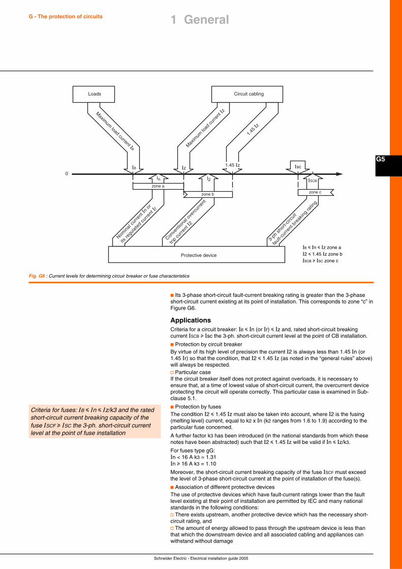
Schneider Electric - Electrical installation guide 2005
G5
G - The protection of circuits 1 General
Loads Circuit cabling
Max
imum
load
curre
nt Iz
1.45
Iz
Maxim
um load current IB
Protective device
0
zone a
zone b zone c
In I2
IzIB 1.45 Iz Isc
ISCB
Nomin
al c
urre
nt In
or
its re
gula
ted
curre
nt Ir
Conve
ntio
nal o
verc
urre
nt
trip
curre
nt I2
3-ph
sho
rt-cir
cuit
faul
t-cur
rent
bre
akin
g ra
ting
Fig. G6 : Current levels for determining circuir breaker or fuse characteristics
IB i In i Iz zone aI2 i 1.45 Iz zone bISCB u ISC zone c
c Its 3-phase short-circuit fault-current breaking rating is greater than the 3-phaseshort-circuit current existing at its point of installation. This corresponds to zone “c” inFigure G6.
ApplicationsCriteria for a circuit breaker: IB i In (or Ir) i Iz and, rated short-circuit breakingcurrent ISCB u Isc the 3-ph. short-circuit current level at the point of CB installation.
c Protection by circuit breakerBy virtue of its high level of precision the current I2 is always less than 1.45 In (or1.45 Ir) so that the condition, that I2 i 1.45 Iz (as noted in the “general rules” above)will always be respected.v Particular caseIf the circuit breaker itself does not protect against overloads, it is necessary toensure that, at a time of lowest value of short-circuit current, the overcurrent deviceprotecting the circuit will operate correctly. This particular case is examined in Sub-clause 5.1.
c Protection by fusesThe condition I2 i 1.45 Iz must also be taken into account, where I2 is the fusing(melting level) current, equal to k2 x In (k2 ranges from 1.6 to 1.9) according to theparticular fuse concerned.
A further factor k3 has been introduced (in the national standards from which thesenotes have been abstracted) such that I2 i 1.45 Iz will be valid if In i Iz/k3.
For fuses type gG:In < 16 A k3 = 1.31In u 16 A k3 = 1.10
Moreover, the short-circuit current breaking capacity of the fuse ISCF must exceedthe level of 3-phase short-circuit current at the point of installation of the fuse(s).
c Association of different protective devicesThe use of protective devices which have fault-current ratings lower than the faultlevel existing at their point of installation are permitted by IEC and many nationalstandards in the following conditions:v There exists upstream, another protective device which has the necessary short-circuit rating, andv The amount of energy allowed to pass through the upstream device is less thanthat which the downstream device and all associated cabling and appliances canwithstand without damage
Criteria for fuses: IB i In i Iz/k3 and the ratedshort-circuit current breaking capacity of thefuse ISCF u ISC the 3-ph. short-circuit currentlevel at the point of fuse installation
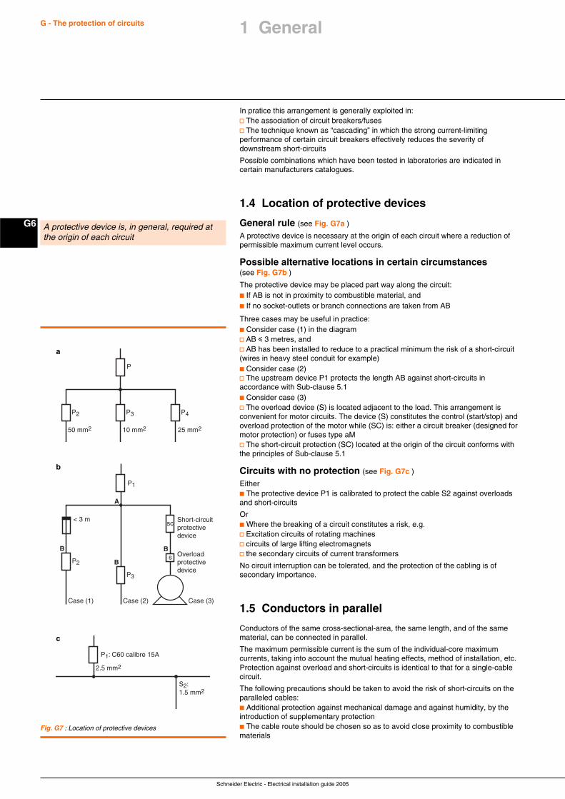
Schneider Electric - Electrical installation guide 2005
G6
G - The protection of circuits
In pratice this arrangement is generally exploited in:v The association of circuit breakers/fusesv The technique known as “cascading” in which the strong current-limitingperformance of certain circuit breakers effectively reduces the severity ofdownstream short-circuits
Possible combinations which have been tested in laboratories are indicated incertain manufacturers catalogues.
1.4 Location of protective devices
General rule (see Fig. G7a )
A protective device is necessary at the origin of each circuit where a reduction ofpermissible maximum current level occurs.
Possible alternative locations in certain circumstances(see Fig. G7b )
The protective device may be placed part way along the circuit:c If AB is not in proximity to combustible material, andc If no socket-outlets or branch connections are taken from AB
Three cases may be useful in practice:c Consider case (1) in the diagramv AB i 3 metres, andv AB has been installed to reduce to a practical minimum the risk of a short-circuit(wires in heavy steel conduit for example)c Consider case (2)v The upstream device P1 protects the length AB against short-circuits inaccordance with Sub-clause 5.1c Consider case (3)v The overload device (S) is located adjacent to the load. This arrangement isconvenient for motor circuits. The device (S) constitutes the control (start/stop) andoverload protection of the motor while (SC) is: either a circuit breaker (designed formotor protection) or fuses type aMv The short-circuit protection (SC) located at the origin of the circuit conforms withthe principles of Sub-clause 5.1
Circuits with no protection (see Fig. G7c )
Eitherc The protective device P1 is calibrated to protect the cable S2 against overloadsand short-circuits
Orc Where the breaking of a circuit constitutes a risk, e.g.v Excitation circuits of rotating machinesv circuits of large lifting electromagnetsv the secondary circuits of current transformers
No circuit interruption can be tolerated, and the protection of the cabling is ofsecondary importance.
1.5 Conductors in parallel
Conductors of the same cross-sectional-area, the same length, and of the samematerial, can be connected in parallel.
The maximum permissible current is the sum of the individual-core maximumcurrents, taking into account the mutual heating effects, method of installation, etc.Protection against overload and short-circuits is identical to that for a single-cablecircuit.
The following precautions should be taken to avoid the risk of short-circuits on theparalleled cables:c Additional protection against mechanical damage and against humidity, by theintroduction of supplementary protectionc The cable route should be chosen so as to avoid close proximity to combustiblematerials
A protective device is, in general, required atthe origin of each circuit
Fig. G7 : Location of protective devices
P
P2 P3 P4
50 mm2 10 mm2 25 mm2
P2
P3
Case (1) Case (2)
Short-circuitprotectivedevice
P1
sc
sB
Overloadprotectivedevice
B
B
< 3 m
A
Case (3)
P1: C60 calibre 15A
S2:1.5 mm2
2.5 mm2
a
b
c
1 General
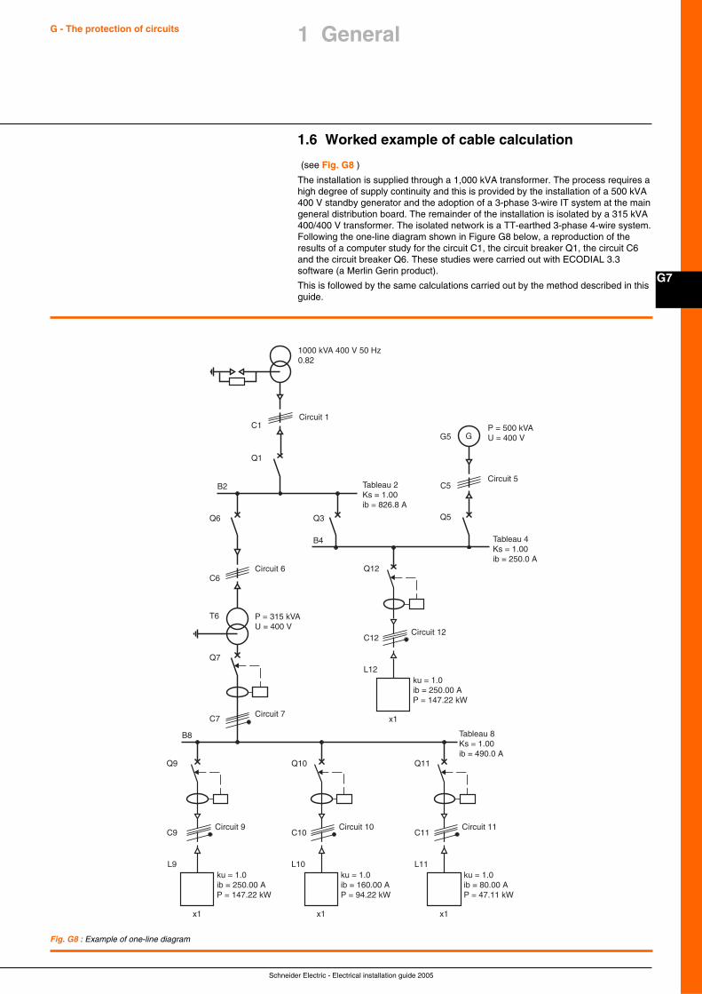
Schneider Electric - Electrical installation guide 2005
G7
G - The protection of circuits 1 General
1.6 Worked example of cable calculation
(see Fig. G8 )
The installation is supplied through a 1,000 kVA transformer. The process requires ahigh degree of supply continuity and this is provided by the installation of a 500 kVA400 V standby generator and the adoption of a 3-phase 3-wire IT system at the maingeneral distribution board. The remainder of the installation is isolated by a 315 kVA400/400 V transformer. The isolated network is a TT-earthed 3-phase 4-wire system.Following the one-line diagram shown in Figure G8 below, a reproduction of theresults of a computer study for the circuit C1, the circuit breaker Q1, the circuit C6and the circuit breaker Q6. These studies were carried out with ECODIAL 3.3software (a Merlin Gerin product).
This is followed by the same calculations carried out by the method described in thisguide.
1000 kVA 400 V 50 Hz0.82
Tableau 2Ks = 1.00ib = 826.8 A
Tableau 4Ks = 1.00ib = 250.0 A
Tableau 8Ks = 1.00ib = 490.0 A
Circuit 6
Circuit 7
P = 315 kVAU = 400 V
Circuit 1C1
Q1
P = 500 kVAU = 400 V
Circuit 5
G
Q5
G5
C5B2
Q6
C6
Q3
B4
B8
T6
Q7
Q9
C7
ku = 1.0ib = 250.00 AP = 147.22 kW
Circuit 9C9
L9
x1
Q12
ku = 1.0ib = 250.00 AP = 147.22 kW
Circuit 12C12
L12
x1
Q10
ku = 1.0ib = 160.00 AP = 94.22 kW
Circuit 10C10
L10
x1
Q11
ku = 1.0ib = 80.00 AP = 47.11 kW
Circuit 11C11
L11
x1
Fig. G8 : Example of one-line diagram
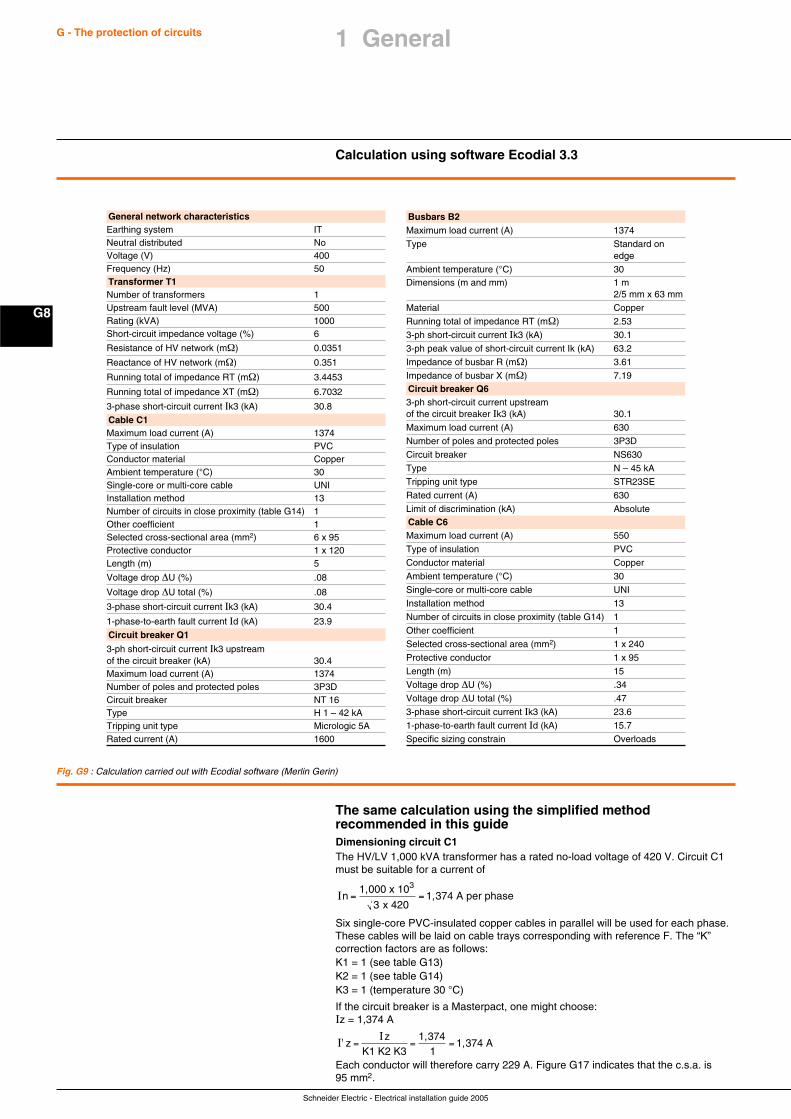
Schneider Electric - Electrical installation guide 2005
G8
G - The protection of circuits
Calculation using software Ecodial 3.3
The same calculation using the simplified methodrecommended in this guideDimensioning circuit C1The HV/LV 1,000 kVA transformer has a rated no-load voltage of 420 V. Circuit C1must be suitable for a current of
In = =1,000 x 10
x 4201,374 A per phase
3
3
Six single-core PVC-insulated copper cables in parallel will be used for each phase.These cables will be laid on cable trays corresponding with reference F. The “K”correction factors are as follows:K1 = 1 (see table G13)K2 = 1 (see table G14)K3 = 1 (temperature 30 °C)
If the circuit breaker is a Masterpact, one might choose:Iz = 1,374 A
I'I
zz
= = =K1 K2 K3
1,3741,374 A
1Each conductor will therefore carry 229 A. Figure G17 indicates that the c.s.a. is95 mm2.
Fig. G9 : Calculation carried out with Ecodial software (Merlin Gerin)
General network characteristicsEarthing system ITNeutral distributed NoVoltage (V) 400Frequency (Hz) 50Transformer T1Number of transformers 1Upstream fault level (MVA) 500Rating (kVA) 1000Short-circuit impedance voltage (%) 6
Resistance of HV network (mΩ) 0.0351
Reactance of HV network (mΩ) 0.351
Running total of impedance RT (mΩ) 3.4453
Running total of impedance XT (mΩ) 6.7032
3-phase short-circuit current Ik3 (kA) 30.8
Cable C1Maximum load current (A) 1374Type of insulation PVCConductor material CopperAmbient temperature (°C) 30Single-core or multi-core cable UNIInstallation method 13Number of circuits in close proximity (table G14) 1Other coefficient 1Selected cross-sectional area (mm2) 6 x 95Protective conductor 1 x 120Length (m) 5
Voltage drop ∆U (%) .08
Voltage drop ∆U total (%) .08
3-phase short-circuit current Ik3 (kA) 30.4
1-phase-to-earth fault current Id (kA) 23.9
Circuit breaker Q1
3-ph short-circuit current Ik3 upstreamof the circuit breaker (kA) 30.4Maximum load current (A) 1374Number of poles and protected poles 3P3DCircuit breaker NT 16Type H 1 – 42 kATripping unit type Micrologic 5ARated current (A) 1600
Busbars B2Maximum load current (A) 1374
Type Standard onedge
Ambient temperature (°C) 30Dimensions (m and mm) 1 m
2/5 mm x 63 mm
Material Copper
Running total of impedance RT (mΩ) 2.53
3-ph short-circuit current Ik3 (kA) 30.1
3-ph peak value of short-circuit current Ik (kA) 63.2
Impedance of busbar R (mΩ) 3.61
Impedance of busbar X (mΩ) 7.19Circuit breaker Q63-ph short-circuit current upstreamof the circuit breaker Ik3 (kA) 30.1
Maximum load current (A) 630
Number of poles and protected poles 3P3D
Circuit breaker NS630
Type N – 45 kA
Tripping unit type STR23SE
Rated current (A) 630
Limit of discrimination (kA) AbsoluteCable C6Maximum load current (A) 550
Type of insulation PVC
Conductor material Copper
Ambient temperature (°C) 30
Single-core or multi-core cable UNI
Installation method 13
Number of circuits in close proximity (table G14) 1
Other coefficient 1
Selected cross-sectional area (mm2) 1 x 240
Protective conductor 1 x 95
Length (m) 15
Voltage drop ∆U (%) .34
Voltage drop ∆U total (%) .47
3-phase short-circuit current Ik3 (kA) 23.6
1-phase-to-earth fault current Id (kA) 15.7
Specific sizing constrain Overloads
1 General
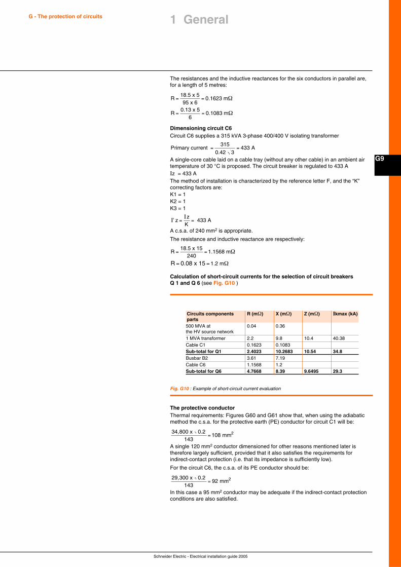
Schneider Electric - Electrical installation guide 2005
G9
G - The protection of circuits 1 General
The resistances and the inductive reactances for the six conductors in parallel are,for a length of 5 metres:
R
R
= =
= =
18.5 x 595 x 6
0.1623 m
0.13 x 56
0.1083 m
Ω
Ω
Dimensioning circuit C6Circuit C6 supplies a 315 kVA 3-phase 400/400 V isolating transformer
Primary current 0.42 3
A= =315
433
A single-core cable laid on a cable tray (without any other cable) in an ambient airtemperature of 30 °C is proposed. The circuit breaker is regulated to 433 AIz = 433 AThe method of installation is characterized by the reference letter F, and the “K”correcting factors are:K1 = 1K2 = 1K3 = 1
I'I
zz
= =K
433 A
A c.s.a. of 240 mm2 is appropriate.
The resistance and inductive reactance are respectively:
R
R
= =
= =
18.5 x 15240
1.1568 m
1.2 m0.08 x 15
Ω
Ω
Calculation of short-circuit currents for the selection of circuit breakersQ 1 and Q 6 (see Fig. G10 )
Circuits components R (mΩ) X (mΩ) Z (mΩ) Ikmax (kA)parts500 MVA at 0.04 0.36the HV source network1 MVA transformer 2.2 9.8 10.4 40.38Cable C1 0.1623 0.1083Sub-total for Q1 2.4023 10.2683 10.54 34.8Busbar B2 3.61 7.19Cable C6 1.1568 1.2Sub-total for Q6 4.7668 8.39 9.6495 29.3
Fig. G10 : Example of short-circuit current evaluation
The protective conductorThermal requirements: Figures G60 and G61 show that, when using the adiabaticmethod the c.s.a. for the protective earth (PE) conductor for circuit C1 will be:
34,800 x 0.2143
=108 2mm
A single 120 mm2 conductor dimensioned for other reasons mentioned later istherefore largely sufficient, provided that it also satisfies the requirements forindirect-contact protection (i.e. that its impedance is sufficiently low).
For the circuit C6, the c.s.a. of its PE conductor should be:
29,300 x 0.2143
= 92 2mm
In this case a 95 mm2 conductor may be adequate if the indirect-contact protectionconditions are also satisfied.
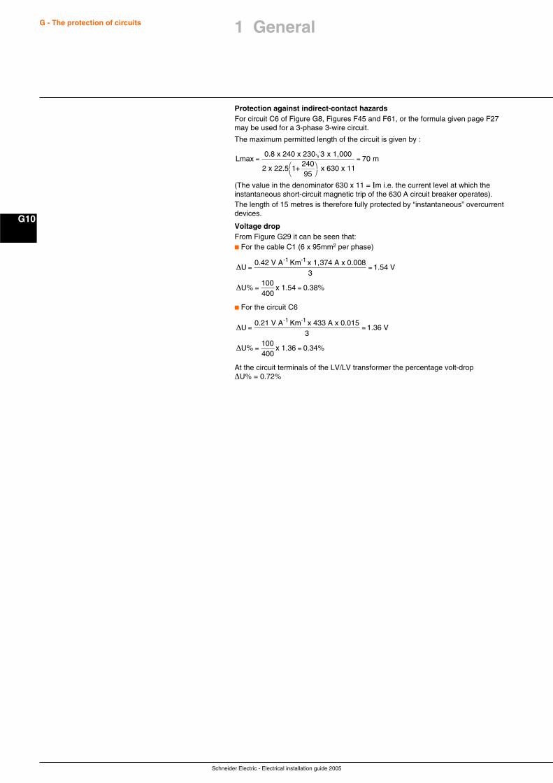
Schneider Electric - Electrical installation guide 2005
G10
G - The protection of circuits 1 General
Protection against indirect-contact hazardsFor circuit C6 of Figure G8, Figures F45 and F61, or the formula given page F27may be used for a 3-phase 3-wire circuit.
The maximum permitted length of the circuit is given by :
Lmax0.8 x 240 x 230 3 x 1,000
2 x 22.5 1+24095
x 630 x 11 m=
⎛⎝
⎞⎠
= 70
(The value in the denominator 630 x 11 = Im i.e. the current level at which theinstantaneous short-circuit magnetic trip of the 630 A circuit breaker operates).The length of 15 metres is therefore fully protected by “instantaneous” overcurrentdevices.
Voltage dropFrom Figure G29 it can be seen that:c For the cable C1 (6 x 95mm2 per phase)
∆
∆
U0.42 V A Km x 1,374 A x 0.008
1.54 V
U%100
1.54 0.38%
-1 -1= =
= =
3
400x
c For the circuit C6
∆
∆
U0.21 V A Km x 433 A x 0.015
1.36 V
U%100
1.36 0.34%
-1 -1= =
= =
3
400x
At the circuit terminals of the LV/LV transformer the percentage volt-drop∆U% = 0.72%
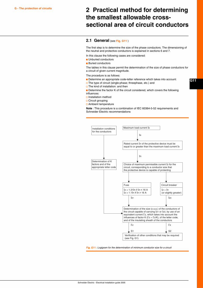
Schneider Electric - Electrical installation guide 2005
G11
G - The protection of circuits 2 Practical method for determiningthe smallest allowable cross-sectional area of circuit conductors
2.1 General (see Fig. G11 )
The first step is to determine the size of the phase conductors. The dimensioning ofthe neutral and protective conductors is explained in sections 6 and 7.
In this clause the following cases are considered:c Unburied conductorsc Buried conductors
The tables in this clause permit the determination of the size of phase conductors fora circuit of given current magnitude.
The procedure is as follows:c Determine an appropriate code-letter reference which takes into account:v The type of circuit (single-phase; threephase, etc.) andv The kind of installation: and thenc Determine the factor K of the circuit considered, which covers the followinginfluences:v Installation methodv Circuit groupingv Ambient temperature
Note : This procedure is a combination of IEC 60364-5-52 requirements andSchneider Electric recommendations
Fig. G11 : Logigram for the determination of minimum conductor size for a circuit
Installation conditionsfor the conductors
Maximum load current IB
Rated current In of the protective device must be equal to or greater than the maximum load current IB
Choice of maximum permissible current Iz for the circuit, corresponding to a conductor size that the protective device is capable of protecting
Determination of the size (c.s.a.) of the conductors of the circuit capable of carrying Iz1 or Iz2, by use of an equivalent current I'z, which takes into account the influences of factor K (I'z = I'z/K), of the letter code, and of the insulating sheath of the conductors
Verification of other conditions that may be required(see Fig. G1)
Iz = 1.31In if In i 16 AIz = 1.1In if In u 16 A
Iz = In(or slightly greater)
Iz1 Iz2
I'z I'z
S1 S2
Fuse Circuit breaker
Determination of Kfactors and of theappropriate letter code
IB
In
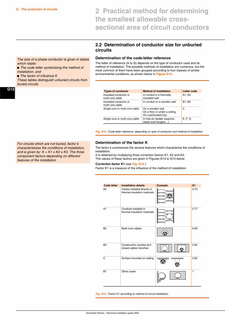
Schneider Electric - Electrical installation guide 2005
G12
G - The protection of circuits
2.2 Determination of conductor size for unburiedcircuits
Determination of the code-letter referenceThe letter of reference (A to G) depends on the type of conductor used and itsmethod of installation. The possible methods of installation are numerous, but themost common of them have been grouped according to four classes of similarenvironmental conditions, as shown below in Figure G12 .
The size of a phase conductor is given in tableswhich relate:c The code letter symbolizing the method ofinstallation, andc The factor of influence KThese tables distinguish unburied circuits fromburied circuits
Types of conductor Method of installation Letter codeInsulated conductor or In conduit in a thermally A1, A2multi core cable insulated wallInsulated conductor or In conduit on a wooden wall B1, B2multi core cableSingle core or multi core cable On a wooden wall C
On a floor or under a ceilingOn a perforated tray
Single core or multi core cable In free air (ladder supports, E, F, Gcleats and hangers…)
Fig. G12 : Code-letter reference, depending on type of conductor and method of installation
Determination of the factor KThe factor k summarizes the several features which characterize the conditions ofinstallation.It is obtained by multiplying three correction factors K1, K2 and K3.The values of these factors are given in Figures G13 to G15 below.
Correction factor K1 (see Fig. G13 )Factor K1 is a measure of the influence of the method of installation.
For circuits which are not buried, factor kcharacteristizes the conditions of installation,and is given by: K = K1 x K2 x K3. The threecomponent factors depending on differentfeatures of the installation
Fig. G13 : Factor K1 according to method of circuit installation
Code letter Installation details Example K1A2 Cables installed directly in 0.70
thermal-insulation materials
A1 Conduits installed in 0.77thermal-insulation materials
B2 Multi-core cables 0.90
B2 Construction cavities and 0.95closed cables trenches
C Surface mounted on ceiling 0.95
B1 Other cases 1
2 Practical method for determiningthe smallest allowable cross-sectional area of circuit conductors
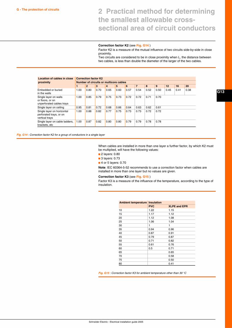
Schneider Electric - Electrical installation guide 2005
G13
G - The protection of circuits 2 Practical method for determiningthe smallest allowable cross-sectional area of circuit conductors
Correction factor K2 (see Fig. G14 )Factor K2 is a measure of the mutual influence of two circuits side-by-side in closeproximity.Two circuits are considered to be in close proximity when L, the distance betweentwo cables, is less than double the diameter of the larger of the two cables.
Fig. G14 : Correction factor K2 for a group of conductors in a single layer
Location of cables in close Correction factor K2proximity Number of circuits or multicore cables
1 2 3 4 5 6 7 8 9 12 16 20Embedded or buried 1.00 0.80 0.70 0.65 0.60 0.57 0.54 0.52 0.50 0.45 0.41 0.38in the wallsSingle layer on walls 1.00 0.85 0.79 0.75 0.73 0.72 0.72 0.71 0.70or floors, or onunperforated cables traysSingle layer on ceiling 0.95 0.81 0.72 0.68 0.66 0.64 0.63 0.62 0.61Single layer on horizontal 1.00 0.88 0.82 0.77 0.75 0.73 0.73 0.72 0.72perforated trays, or onvertical traysSingle layer on cable ladders, 1.00 0.87 0.82 0.80 0.80 0.79 0.79 0.78 0.78brackets, etc
When cables are installed in more than one layer a further factor, by which K2 mustbe multiplied, will have the following values:c 2 layers: 0.80c 3 layers: 0.73c 4 or 5 layers: 0.70
Note: IEC 60364-5-52 recommends to use a correction factor when cables areinstalled in more than one layer but no values are given.
Correction factor K3 (see Fig. G15 )Factor K3 is a measure of the influence of the temperature, according to the type ofinsulation.
Fig. G15 : Correction factor K3 for ambient temperature other than 30 °C
Ambient temperature InsulationPVC XLPE and EPR
10 1.22 1.1515 1.17 1.1220 1.12 1.0825 1.06 1.0430 1 135 0.94 0.9640 0.87 0.9145 0.79 0.8750 0.71 0.8255 0.61 0.7660 0.5 0.7165 0.6570 0.5875 0.5080 0.41
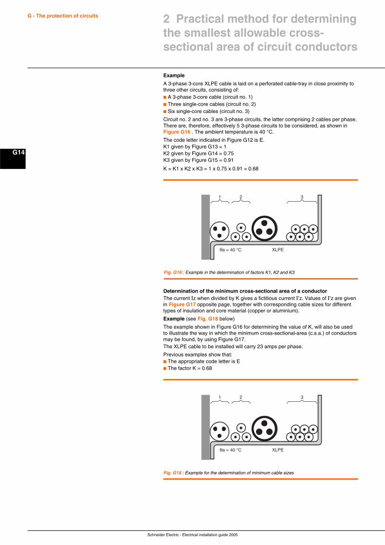
Schneider Electric - Electrical installation guide 2005
G14
G - The protection of circuits
Example
A 3-phase 3-core XLPE cable is laid on a perforated cable-tray in close proximity tothree other circuits, consisting of:c A 3-phase 3-core cable (circuit no. 1)c Three single-core cables (circuit no. 2)c Six single-core cables (circuit no. 3)
Circuit no. 2 and no. 3 are 3-phase circuits, the latter comprising 2 cables per phase.There are, therefore, effectively 5 3-phase circuits to be considered, as shown inFigure G16 . The ambient temperature is 40 °C.
The code letter indicated in Figure G12 is E.K1 given by Figure G13 = 1K2 given by Figure G14 = 0.75K3 given by Figure G15 = 0.91
K = K1 x K2 x K3 = 1 x 0.75 x 0.91 = 0.68
Fig. G16 : Example in the determination of factors K1, K2 and K3
321
XLPE
Determination of the minimum cross-sectional area of a conductorThe current Iz when divided by K gives a fictitious current I’z. Values of I’z are givenin Figure G17 opposite page, together with corresponding cable sizes for differenttypes of insulation and core material (copper or aluminium).
Example (see Fig. G18 below)
The example shown in Figure G16 for determining the value of K, will also be usedto illustrate the way in which the minimum cross-sectional-area (c.s.a.) of conductorsmay be found, by using Figure G17.The XLPE cable to be installed will carry 23 amps per phase.
Previous examples show that:c The appropriate code letter is Ec The factor K = 0.68
Fig. G18 : Example for the determination of minimum cable sizes
321
XLPEθa = 40 °C
2 Practical method for determiningthe smallest allowable cross-sectional area of circuit conductors
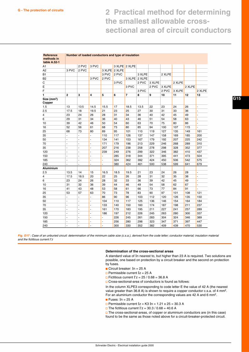
Schneider Electric - Electrical installation guide 2005
G15
G - The protection of circuits 2 Practical method for determiningthe smallest allowable cross-sectional area of circuit conductors
Fig. G17 : Case of an unburied circuit: determination of the minimum cable size (c.s.a.), derived from the code letter; conductor material; insulation materialand the fictitious current I’z
Determination of the cross-sectional areasA standard value of In nearest to, but higher than 23 A is required. Two solutions arepossible, one based on protection by a circuit breaker and the second on protectionby fuses.c Circuit breaker: In = 25 Av Permissible current Iz = 25 Av Fictitious current I’z = 25 / 0.68 = 36.8 Av Cross-sectional-area of conductors is found as follows:
In the column XLPE3 corresponding to code letter E the value of 42 A (the nearestvalue greater than 36.8 A) is shown to require a copper conductor c.s.a. of 4 mm2.For an aluminium conductor the corresponding values are 42 A and 6 mm2.c Fuses: In = 25 Av Permissible current Iz = K3 In = 1.21 x 25 = 30.3 Av The fictitious current I’z = 30.3 / 0.68 = 40.6 Av The cross-sectional-areas, of copper or aluminium conductors are (in this case)found to be the same as those noted above for a circuit-breaker-protected circuit.
Reference Number of loaded conductors and type of insulationmethods intable A.52-1A1 2 PVC 3 PVC 3 XLPE 2 XLPEA2 3 PVC 2 PVC 3 XLPE 2 XLPEB1 3 PVC 2 PVC 3 XLPE 2 XLPEB2 3 PVC 2 PVC 3 XLPE 2 XLPEC 3 PVC 2 PVC 3 XLPE 2 XLPEE 3 PVC 2 PVC 3 XLPE 2 XLPEF 3 PVC 2 PVC 3 XLPE 2 XLPE1 2 3 4 5 6 7 8 9 10 11 12 13Size (mm2)Copper1.5 13 13.5 14.5 15.5 17 18.5 13.5 22 23 24 26 -2.5 17.5 18 19.5 21 23 25 27 30 31 33 36 -4 23 24 26 28 31 34 36 40 42 45 49 -6 29 31 34 36 40 43 46 51 54 58 63 -10 39 42 46 50 54 60 63 70 75 80 86 -16 52 56 61 68 73 80 85 94 100 107 115 -25 68 73 80 89 95 101 110 119 127 135 149 16135 - - - 110 117 126 137 147 158 169 185 20050 - - - 134 141 153 167 179 192 207 225 24270 - - - 171 179 196 213 229 246 268 289 31035 - - - 207 216 238 258 278 298 328 352 377120 - - - 239 249 276 299 322 346 382 410 437150 - - - - 285 318 344 371 395 441 473 504185 - - - - 324 362 392 424 450 506 542 575240 - - - - 380 424 461 500 538 599 641 679Aluminium2.5 13.5 14 15 16.5 18.5 19.5 21 23 24 26 28 -4 17.5 18.5 20 22 25 26 28 31 32 35 38 -6 23 24 26 28 32 33 36 39 42 45 49 -10 31 32 36 39 44 46 49 54 58 62 67 -16 41 43 48 53 58 61 66 73 77 84 91 -25 53 57 63 70 73 78 83 90 97 101 108 12135 - - - 86 90 96 103 112 120 126 135 15050 - - - 104 110 117 125 136 146 154 164 18470 - - - 133 140 150 160 174 187 198 211 23735 - - - 161 170 183 195 211 227 241 257 289120 - - - 186 197 212 226 245 263 280 300 337150 - - - - 226 245 261 283 304 324 346 389185 - - - - 256 280 298 323 347 371 397 447240 - - - - 300 330 352 382 409 439 470 530
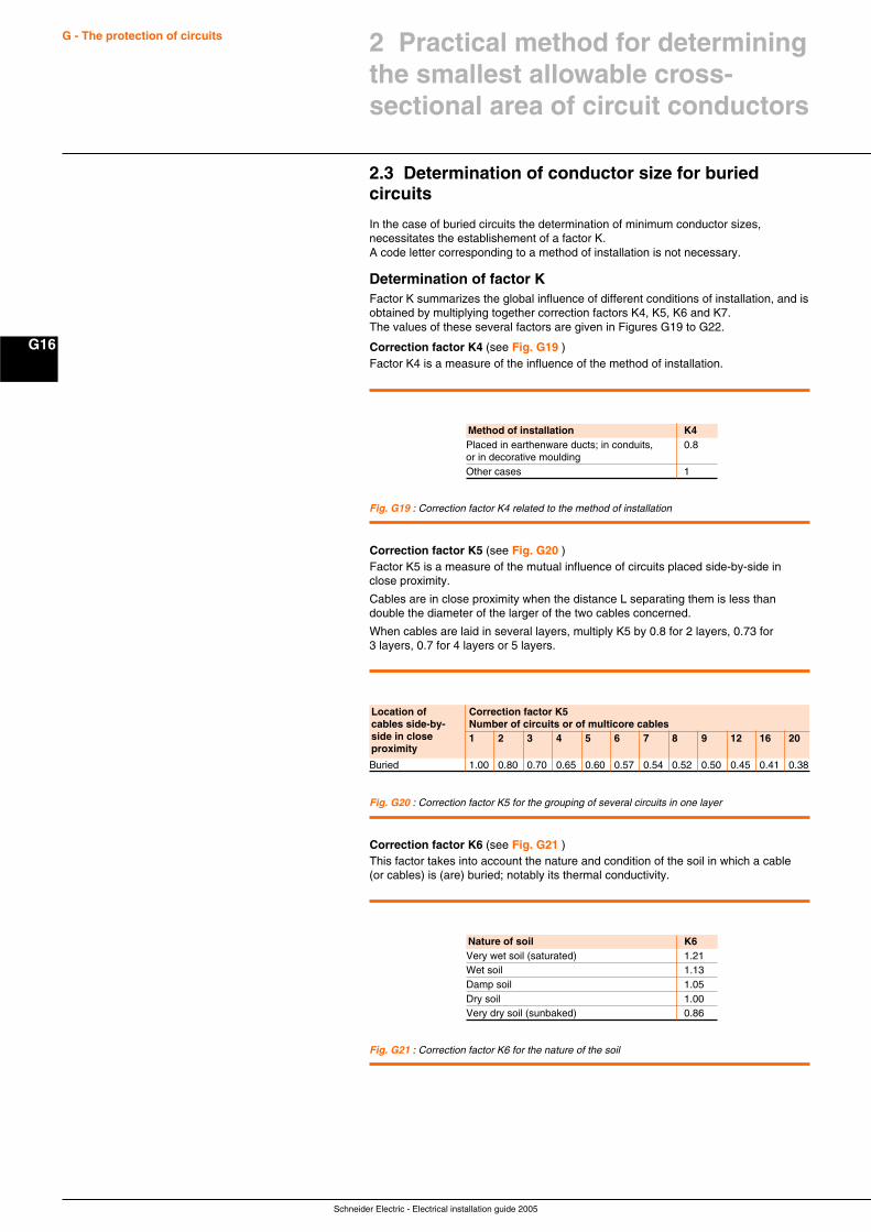
Schneider Electric - Electrical installation guide 2005
G16
G - The protection of circuits
2.3 Determination of conductor size for buriedcircuits
In the case of buried circuits the determination of minimum conductor sizes,necessitates the establishement of a factor K.A code letter corresponding to a method of installation is not necessary.
Determination of factor KFactor K summarizes the global influence of different conditions of installation, and isobtained by multiplying together correction factors K4, K5, K6 and K7.The values of these several factors are given in Figures G19 to G22.
Correction factor K4 (see Fig. G19 )Factor K4 is a measure of the influence of the method of installation.
Fig. G19 : Correction factor K4 related to the method of installation
Method of installation K4Placed in earthenware ducts; in conduits, 0.8or in decorative mouldingOther cases 1
Correction factor K5 (see Fig. G20 )Factor K5 is a measure of the mutual influence of circuits placed side-by-side inclose proximity.
Cables are in close proximity when the distance L separating them is less thandouble the diameter of the larger of the two cables concerned.
When cables are laid in several layers, multiply K5 by 0.8 for 2 layers, 0.73 for3 layers, 0.7 for 4 layers or 5 layers.
Fig. G20 : Correction factor K5 for the grouping of several circuits in one layer
Location of Correction factor K5cables side-by- Number of circuits or of multicore cablesside in close 1 2 3 4 5 6 7 8 9 12 16 20proximity
Buried 1.00 0.80 0.70 0.65 0.60 0.57 0.54 0.52 0.50 0.45 0.41 0.38
Correction factor K6 (see Fig. G21 )This factor takes into account the nature and condition of the soil in which a cable(or cables) is (are) buried; notably its thermal conductivity.
Fig. G21 : Correction factor K6 for the nature of the soil
Nature of soil K6Very wet soil (saturated) 1.21Wet soil 1.13Damp soil 1.05Dry soil 1.00Very dry soil (sunbaked) 0.86
2 Practical method for determiningthe smallest allowable cross-sectional area of circuit conductors
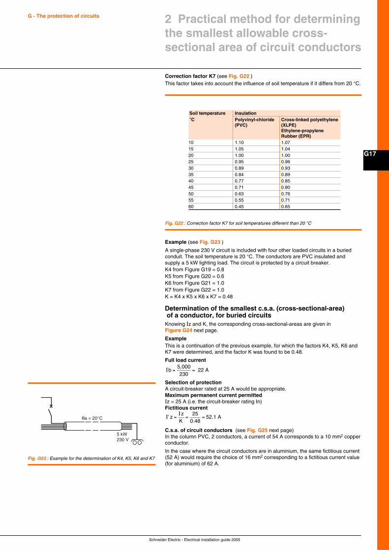
Schneider Electric - Electrical installation guide 2005
G17
G - The protection of circuits 2 Practical method for determiningthe smallest allowable cross-sectional area of circuit conductors
Correction factor K7 (see Fig. G22 )This factor takes into account the influence of soil temperature if it differs from 20 °C.
Fig. G22 : Correction factor K7 for soil temperatures different than 20 °C
Soil temperature Insulation°C Polyvinyl-chloride Cross-linked polyethylene
(PVC) (XLPE)Ethylene-propyleneRubber (EPR)
10 1.10 1.0715 1.05 1.0420 1.00 1.0025 0.95 0.9630 0.89 0.9335 0.84 0.8940 0.77 0.8545 0.71 0.8050 0.63 0.7655 0.55 0.7160 0.45 0.65
Example (see Fig. G23 )
A single-phase 230 V circuit is included with four other loaded circuits in a buriedconduit. The soil temperature is 20 °C. The conductors are PVC insulated andsupply a 5 kW lighting load. The circuit is protected by a circuit breaker.K4 from Figure G19 = 0.8K5 from Figure G20 = 0.6K6 from Figure G21 = 1.0K7 from Figure G22 = 1.0K = K4 x K5 x K6 x K7 = 0.48
Determination of the smallest c.s.a. (cross-sectional-area) of a conductor, for buried circuitsKnowing Iz and K, the corresponding cross-sectional-areas are given inFigure G24 next page.
ExampleThis is a continuation of the previous example, for which the factors K4, K5, K6 andK7 were determined, and the factor K was found to be 0.48.
Full load current
Ib = =5,000230
22 A
Selection of protectionA circuit-breaker rated at 25 A would be appropriate.Maximum permanent current permittedIz = 25 A (i.e. the circuit-breaker rating In)Fictitious current
I'I
zz
= = =K
250.48
5 .1 A2
C.s.a. of circuit conductors (see Fig. G25 next page)In the column PVC, 2 conductors, a current of 54 A corresponds to a 10 mm2 copperconductor.
In the case where the circuit conductors are in aluminium, the same fictitious current(52 A) would require the choice of 16 mm2 corresponding to a fictitious current value(for aluminium) of 62 A.
Fig. G23 : Example for the determination of K4, K5, K6 and K7
θa = 20°C
5 kW230 V
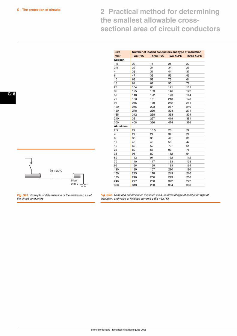
Schneider Electric - Electrical installation guide 2005
G18
G - The protection of circuits 2 Practical method for determiningthe smallest allowable cross-sectional area of circuit conductors
Fig. G25 : Example of determination of the minimum c.s.a ofthe circuit conductors
θa = 20°C
5 kW230 V
Fig. G24 : Case of a buried circuit: minimum c.s.a. in terms of type of conductor; type ofinsulation; and value of fictitious current I’z (I’z = Iz / K)
Size Number of loaded conductors and type of insulationmm2 Two PVC Three PVC Two XLPE Three XLPECopper1.5 22 18 26 222.5 29 24 34 294 38 31 44 376 47 39 56 4610 63 52 73 6116 81 67 95 7925 104 86 121 10135 125 103 146 12250 148 122 173 14470 183 151 213 17895 216 179 252 211120 246 203 287 240150 278 230 324 271185 312 258 363 304240 361 297 419 351300 408 336 474 396Aluminium2.5 22 18.5 26 224 29 24 34 296 36 30 42 3610 48 40 56 4716 62 52 73 6125 80 66 93 7835 96 80 112 9450 113 94 132 11270 140 117 163 13895 166 138 193 164120 189 157 220 186150 213 178 249 210185 240 200 279 236240 277 230 322 272300 313 260 364 308
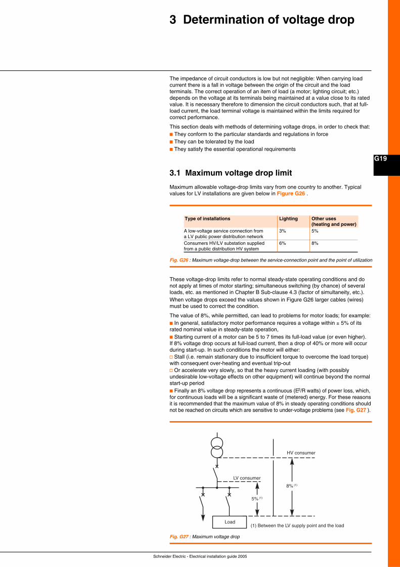
Schneider Electric - Electrical installation guide 2005
G19
3 Determination of voltage drop
The impedance of circuit conductors is low but not negligible: When carrying loadcurrent there is a fall in voltage between the origin of the circuit and the loadterminals. The correct operation of an item of load (a motor; lighting circuit; etc.)depends on the voltage at its terminals being maintained at a value close to its ratedvalue. It is necessary therefore to dimension the circuit conductors such, that at full-load current, the load terminal voltage is maintained within the limits required forcorrect performance.
This section deals with methods of determining voltage drops, in order to check that:c They conform to the particular standards and regulations in forcec They can be tolerated by the loadc They satisfy the essential operational requirements
3.1 Maximum voltage drop limit
Maximum allowable voltage-drop limits vary from one country to another. Typicalvalues for LV installations are given below in Figure G26 .
Fig. G26 : Maximum voltage-drop between the service-connection point and the point of utilization
Fig. G27 : Maximum voltage drop
Type of installations Lighting Other uses(heating and power)
A low-voltage service connection from 3% 5%a LV public power distribution networkConsumers HV/LV substation supplied 6% 8%from a public distribution HV system
These voltage-drop limits refer to normal steady-state operating conditions and donot apply at times of motor starting; simultaneous switching (by chance) of severalloads, etc. as mentioned in Chapter B Sub-clause 4.3 (factor of simultaneity, etc.).When voltage drops exceed the values shown in Figure G26 larger cables (wires)must be used to correct the condition.
The value of 8%, while permitted, can lead to problems for motor loads; for example:c In general, satisfactory motor performance requires a voltage within ± 5% of itsrated nominal value in steady-state operation,c Starting current of a motor can be 5 to 7 times its full-load value (or even higher).If 8% voltage drop occurs at full-load current, then a drop of 40% or more will occurduring start-up. In such conditions the motor will either:v Stall (i.e. remain stationary due to insufficient torque to overcome the load torque)with consequent over-heating and eventual trip-outv Or accelerate very slowly, so that the heavy current loading (with possiblyundesirable low-voltage effects on other equipment) will continue beyond the normalstart-up periodc Finally an 8% voltage drop represents a continuous (E2/R watts) of power loss, which,for continuous loads will be a significant waste of (metered) energy. For these reasonsit is recommended that the maximum value of 8% in steady operating conditions shouldnot be reached on circuits which are sensitive to under-voltage problems (see Fig. G27 ).
Load
LV consumer
5% (1)
8% (1)
HV consumer
(1) Between the LV supply point and the load
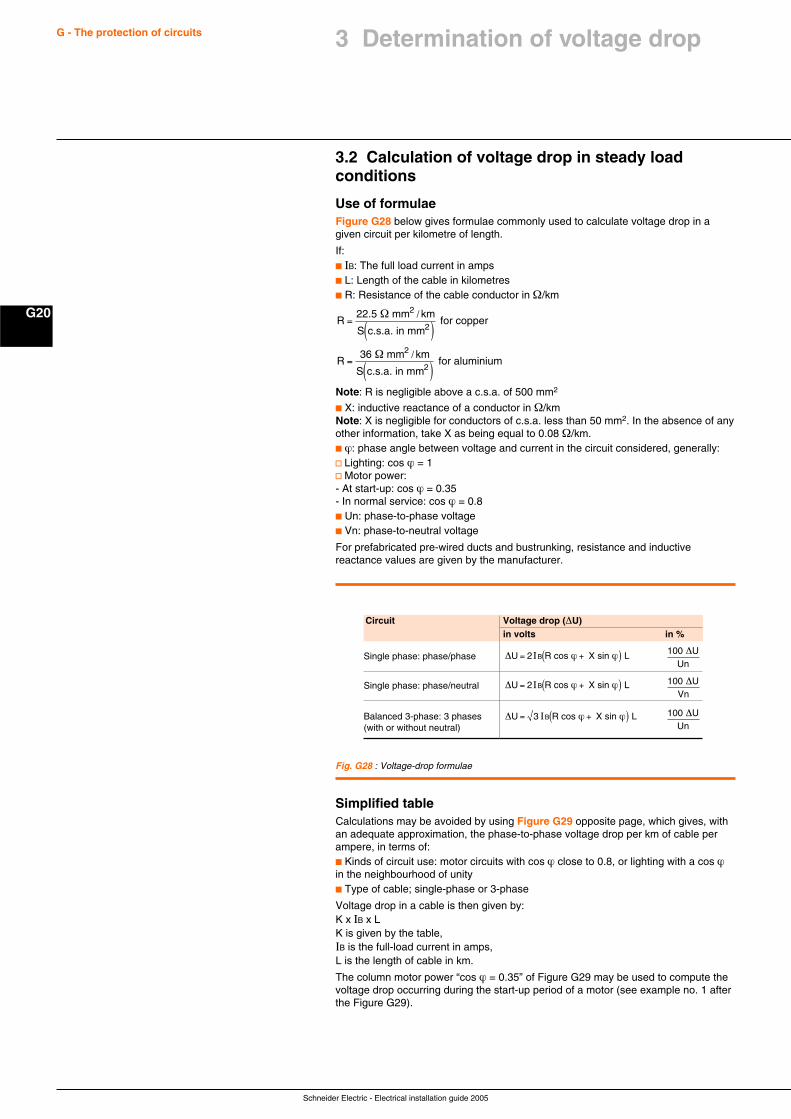
Schneider Electric - Electrical installation guide 2005
G20
G - The protection of circuits
3.2 Calculation of voltage drop in steady loadconditions
Use of formulaeFigure G28 below gives formulae commonly used to calculate voltage drop in agiven circuit per kilometre of length.
If:c IB: The full load current in ampsc L: Length of the cable in kilometresc R: Resistance of the cable conductor in Ω/km
Rkm
S
Rkm
S
=( )
=( )
22.5 mm
c.s.a. in mm for copper
36 mm
c.s.a. in mm for aluminium
2
2
2
2
Ω
Ω
/
/
Note: R is negligible above a c.s.a. of 500 mm2
c X: inductive reactance of a conductor in Ω/kmNote: X is negligible for conductors of c.s.a. less than 50 mm2. In the absence of anyother information, take X as being equal to 0.08 Ω/km.c ϕ: phase angle between voltage and current in the circuit considered, generally:v Lighting: cos ϕ = 1v Motor power:- At start-up: cos ϕ = 0.35- In normal service: cos ϕ = 0.8c Un: phase-to-phase voltagec Vn: phase-to-neutral voltage
For prefabricated pre-wired ducts and bustrunking, resistance and inductivereactance values are given by the manufacturer.
Fig. G28 : Voltage-drop formulae
Circuit Voltage drop (∆U)in volts in %
Single phase: phase/phase ∆U cos X sin = +( )2IB R Lϕ ϕ 100 UUn∆
Single phase: phase/neutral ∆U cos X sin = +( )2IB R Lϕ ϕ 100 UVn∆
Balanced 3-phase: 3 phases ∆U cos X sin = +( )3 IB R Lϕ ϕ 100 UUn∆
(with or without neutral)
Simplified tableCalculations may be avoided by using Figure G29 opposite page, which gives, withan adequate approximation, the phase-to-phase voltage drop per km of cable perampere, in terms of:c Kinds of circuit use: motor circuits with cos ϕ close to 0.8, or lighting with a cos ϕin the neighbourhood of unityc Type of cable; single-phase or 3-phase
Voltage drop in a cable is then given by:K x IB x LK is given by the table,IB is the full-load current in amps,L is the length of cable in km.
The column motor power “cos ϕ = 0.35” of Figure G29 may be used to compute thevoltage drop occurring during the start-up period of a motor (see example no. 1 afterthe Figure G29).
3 Determination of voltage drop
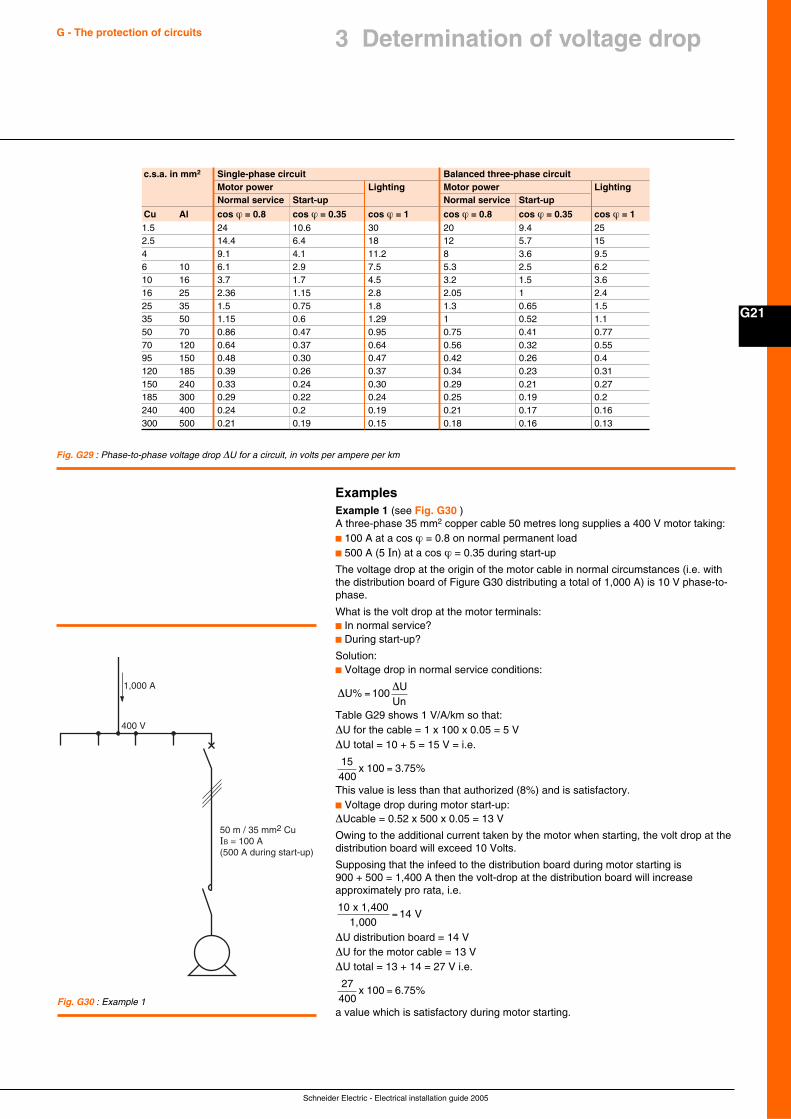
Schneider Electric - Electrical installation guide 2005
G21
G - The protection of circuits 3 Determination of voltage drop
c.s.a. in mm2 Single-phase circuit Balanced three-phase circuitMotor power Lighting Motor power LightingNormal service Start-up Normal service Start-up
Cu Al cos ϕ = 0.8 cos ϕ = 0.35 cos ϕ = 1 cos ϕ = 0.8 cos ϕ = 0.35 cos ϕ = 11.5 24 10.6 30 20 9.4 252.5 14.4 6.4 18 12 5.7 154 9.1 4.1 11.2 8 3.6 9.56 10 6.1 2.9 7.5 5.3 2.5 6.210 16 3.7 1.7 4.5 3.2 1.5 3.616 25 2.36 1.15 2.8 2.05 1 2.425 35 1.5 0.75 1.8 1.3 0.65 1.535 50 1.15 0.6 1.29 1 0.52 1.150 70 0.86 0.47 0.95 0.75 0.41 0.7770 120 0.64 0.37 0.64 0.56 0.32 0.5595 150 0.48 0.30 0.47 0.42 0.26 0.4120 185 0.39 0.26 0.37 0.34 0.23 0.31150 240 0.33 0.24 0.30 0.29 0.21 0.27185 300 0.29 0.22 0.24 0.25 0.19 0.2240 400 0.24 0.2 0.19 0.21 0.17 0.16300 500 0.21 0.19 0.15 0.18 0.16 0.13
Fig. G29 : Phase-to-phase voltage drop ∆U for a circuit, in volts per ampere per km
ExamplesExample 1 (see Fig. G30 )A three-phase 35 mm2 copper cable 50 metres long supplies a 400 V motor taking:c 100 A at a cos ϕ = 0.8 on normal permanent loadc 500 A (5 In) at a cos ϕ = 0.35 during start-up
The voltage drop at the origin of the motor cable in normal circumstances (i.e. withthe distribution board of Figure G30 distributing a total of 1,000 A) is 10 V phase-to-phase.
What is the volt drop at the motor terminals:c In normal service?c During start-up?
Solution:c Voltage drop in normal service conditions:
∆∆
U% 100U
=Un
Table G29 shows 1 V/A/km so that:∆U for the cable = 1 x 100 x 0.05 = 5 V∆U total = 10 + 5 = 15 V = i.e.
15400
100 3x .75%=
This value is less than that authorized (8%) and is satisfactory.c Voltage drop during motor start-up:∆Ucable = 0.52 x 500 x 0.05 = 13 V
Owing to the additional current taken by the motor when starting, the volt drop at thedistribution board will exceed 10 Volts.
Supposing that the infeed to the distribution board during motor starting is900 + 500 = 1,400 A then the volt-drop at the distribution board will increaseapproximately pro rata, i.e.
1014
1,4001,000
Vx
=
∆U distribution board = 14 V∆U for the motor cable = 13 V∆U total = 13 + 14 = 27 V i.e.
27400
100 6x .75%=
a value which is satisfactory during motor starting.Fig. G30 : Example 1
1,000 A
400 V
50 m / 35 mm2 CuIB = 100 A(500 A during start-up)
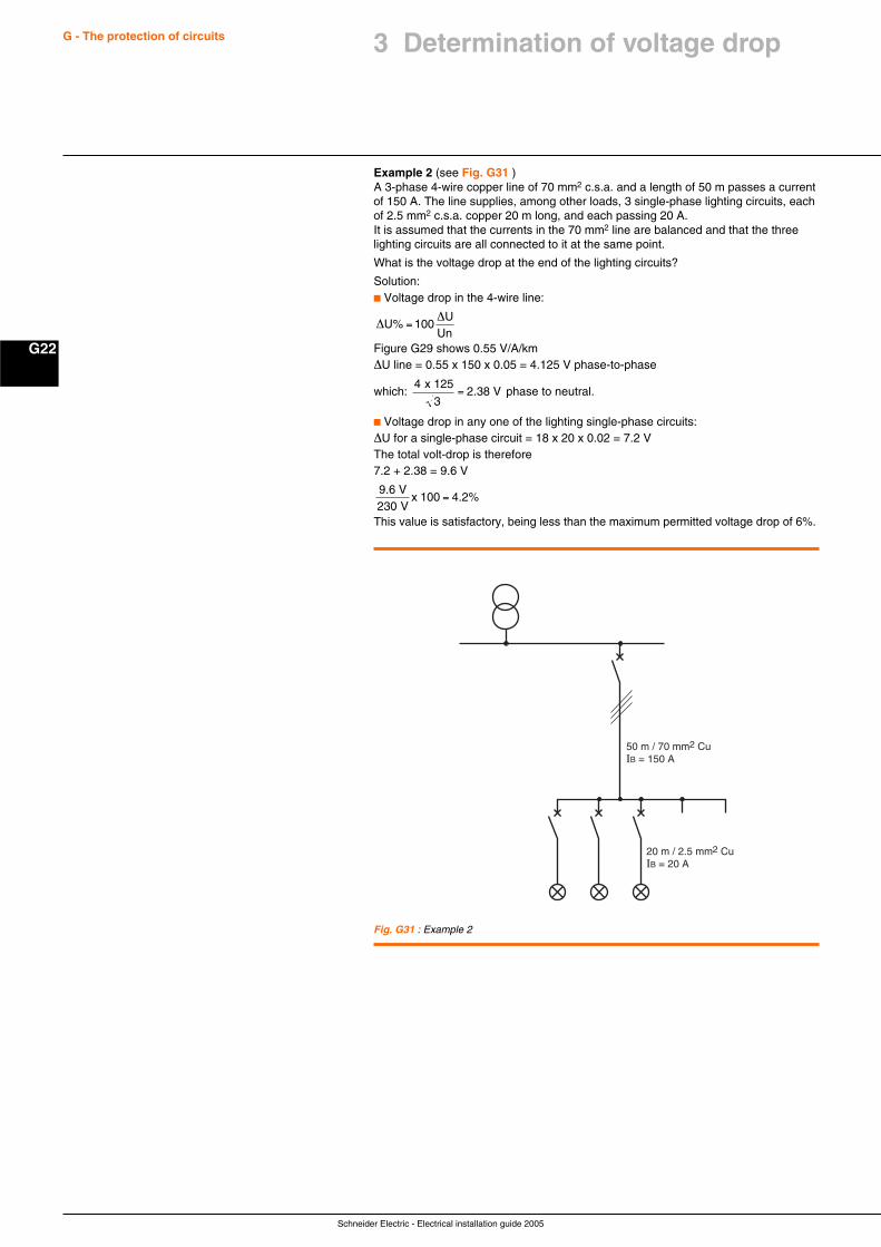
Schneider Electric - Electrical installation guide 2005
G22
G - The protection of circuits 3 Determination of voltage drop
Example 2 (see Fig. G31 )A 3-phase 4-wire copper line of 70 mm2 c.s.a. and a length of 50 m passes a currentof 150 A. The line supplies, among other loads, 3 single-phase lighting circuits, eachof 2.5 mm2 c.s.a. copper 20 m long, and each passing 20 A.It is assumed that the currents in the 70 mm2 line are balanced and that the threelighting circuits are all connected to it at the same point.
What is the voltage drop at the end of the lighting circuits?
Solution:c Voltage drop in the 4-wire line:
∆∆
U% 100U
=Un
Figure G29 shows 0.55 V/A/km∆U line = 0.55 x 150 x 0.05 = 4.125 V phase-to-phase
which: 4 125
32.38 V
x= phase to neutral.
c Voltage drop in any one of the lighting single-phase circuits:∆U for a single-phase circuit = 18 x 20 x 0.02 = 7.2 VThe total volt-drop is therefore7.2 + 2.38 = 9.6 V
9.6 V V
.2%230
100 4x =
This value is satisfactory, being less than the maximum permitted voltage drop of 6%.
Fig. G31 : Example 2
50 m / 70 mm2 CuIB = 150 A
20 m / 2.5 mm2 CuIB = 20 A
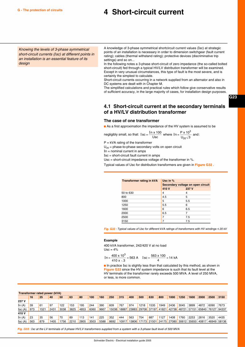
Schneider Electric - Electrical installation guide 2005
G23
G - The protection of circuits 4 Short-circuit current
A knowledge of 3-phase symmetrical shortcircuit current values (Isc) at strategicpoints of an installation is necessary in order to dimension switchgear (fault currentrating); cables (thermal withstand rating); protective devices (discriminative tripsettings) and so on...In the following notes a 3-phase short-circuit of zero impedance (the so-called boltedshort-circuit) fed through a typical HV/LV distribution transformer will be examined.Except in very unusual circumstances, this type of fault is the most severe, and iscertainly the simplest to calculate.Short-circuit currents occurring in a network supplied from an alternator and also inDC systems are dealt with in Chapter M.The simplified calculations and practical rules which follow give conservative resultsof sufficient accuracy, in the large majority of cases, for installation design purposes.
4.1 Short-circuit current at the secondary terminalsof a HV/LV distribution transformer
The case of one transformerc As a first approximation the impedance of the HV system is assumed to be
negligibly small, so that: II
IscnUsc
nP
U= =
x 100 where
x 10 and:
3
20 3
P = kVA rating of the transformerU20 = phase-to-phase secondary volts on open circuitIn = nominal current in ampsIsc = short-circuit fault current in ampsUsc = short-circuit impedance voltage of the transformer in %.
Typical values of Usc for distribution transformers are given in Figure G32 .
Fig. G32 : Typical values of Usc for different kVA ratings of transformers with HV windings i 20 kV
Transformer rating in kVA Usc in %Secondary voltage on open circuit410 V 237 V
50 to 630 4 4800 4.5 51000 5 5.51250 5.5 61600 6 6.52000 6.5 72500 7 7.53150 7 7.5
Example
400 kVA transformer, 242/420 V at no loadUsc = 4%
I In sc= = = =4
410 3563
54
1400 x 10
x A
63 x 100 kA
3
c In practice Isc is slightly less than that calculated by this method, as shown inFigure G33 since the HV system impedance is such that its fault level at theHV terminals of the transformer rarely exceeds 500 MVA. A level of 250 MVA,or less, is more common.
Fig. G33 : Isc at the LV terminals of 3-phase HV/LV transformers supplied from a system with a 3-phase fault level of 500 MVA
Transformer rated power (kVA)16 25 40 50 63 80 100 160 250 315 400 500 630 800 1000 1250 1600 2000 2500 3150
237 VIn (A) 39 61 97 122 153 195 244 390 609 767 974 1218 1535 1949 2436 3045 3899 4872 6090 7673Isc (A) 973 1521 2431 3038 3825 4853 6060 9667 15038 18887 23883 29708 37197 41821 42738 48721 57151 65840 76127 94337410 VIn (A) 23 35 56 70 89 113 141 225 352 444 563 704 887 1127 1408 1760 2253 2816 3520 4435Isc (A) 563 879 1405 1756 2210 2805 3503 5588 8692 10917 13806 17173 21501 24175 27080 30612 35650 40817 46949 58136
Knowing the levels of 3-phase symmetricalshort-circuit currents (Isc) at different points inan installation is an essential feature of itsdesign
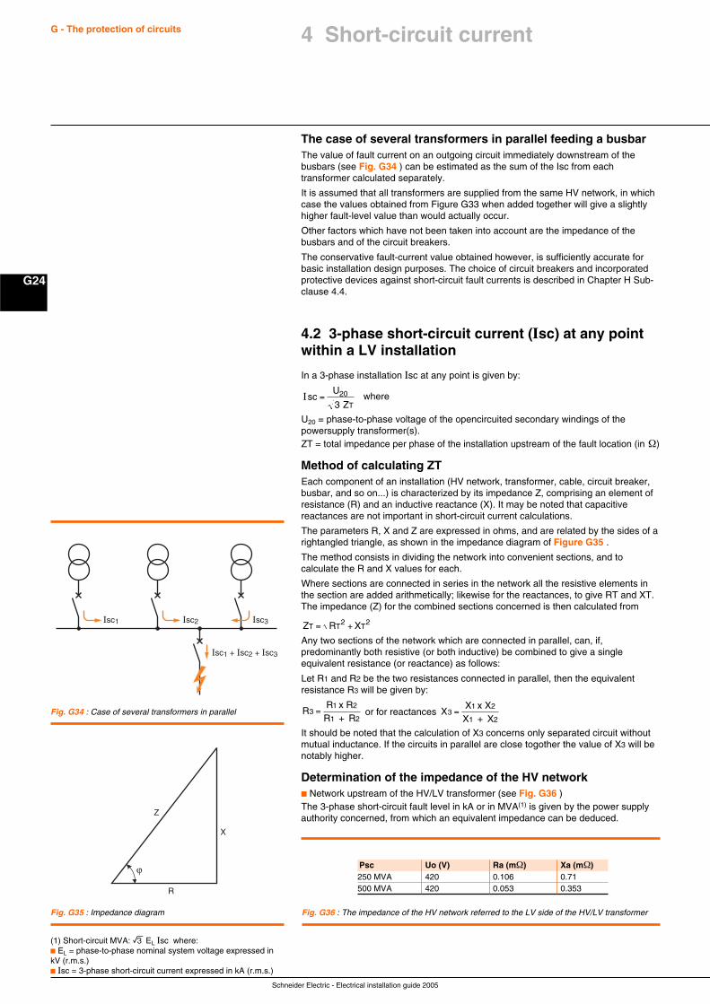
Schneider Electric - Electrical installation guide 2005
G24
G - The protection of circuits
The case of several transformers in parallel feeding a busbarThe value of fault current on an outgoing circuit immediately downstream of thebusbars (see Fig. G34 ) can be estimated as the sum of the Isc from eachtransformer calculated separately.
It is assumed that all transformers are supplied from the same HV network, in whichcase the values obtained from Figure G33 when added together will give a slightlyhigher fault-level value than would actually occur.
Other factors which have not been taken into account are the impedance of thebusbars and of the circuit breakers.
The conservative fault-current value obtained however, is sufficiently accurate forbasic installation design purposes. The choice of circuit breakers and incorporatedprotective devices against short-circuit fault currents is described in Chapter H Sub-clause 4.4.
4.2 3-phase short-circuit current (Isc) at any pointwithin a LV installation
In a 3-phase installation Isc at any point is given by:
IscU
ZT= 20
3 where
U20 = phase-to-phase voltage of the opencircuited secondary windings of thepowersupply transformer(s).ZT = total impedance per phase of the installation upstream of the fault location (in Ω)
Method of calculating ZTEach component of an installation (HV network, transformer, cable, circuit breaker,busbar, and so on...) is characterized by its impedance Z, comprising an element ofresistance (R) and an inductive reactance (X). It may be noted that capacitivereactances are not important in short-circuit current calculations.
The parameters R, X and Z are expressed in ohms, and are related by the sides of arightangled triangle, as shown in the impedance diagram of Figure G35 .
The method consists in dividing the network into convenient sections, and tocalculate the R and X values for each.
Where sections are connected in series in the network all the resistive elements inthe section are added arithmetically; likewise for the reactances, to give RT and XT.The impedance (Z) for the combined sections concerned is then calculated from
Z R XT T T= +2 2
Any two sections of the network which are connected in parallel, can, if,predominantly both resistive (or both inductive) be combined to give a singleequivalent resistance (or reactance) as follows:
Let R1 and R2 be the two resistances connected in parallel, then the equivalentresistance R3 will be given by:
RR
31
= x R
R + R2
1 2 or for reactances X
X3
1=
x XX + X
2
1 2
It should be noted that the calculation of X3 concerns only separated circuit withoutmutual inductance. If the circuits in parallel are close togother the value of X3 will benotably higher.
Determination of the impedance of the HV networkc Network upstream of the HV/LV transformer (see Fig. G36 )The 3-phase short-circuit fault level in kA or in MVA(1) is given by the power supplyauthority concerned, from which an equivalent impedance can be deduced.
Fig. G34 : Case of several transformers in parallel
Fig. G35 : Impedance diagram
Isc1
Isc1 + Isc2 + Isc3
Isc2 Isc3
Z
X
R
Psc Uo (V) Ra (mΩ) Xa (mΩ)250 MVA 420 0.106 0.71500 MVA 420 0.053 0.353
Fig. G36 : The impedance of the HV network referred to the LV side of the HV/LV transformer
(1) Short-circuit MVA: e EL Isc where:c EL = phase-to-phase nominal system voltage expressed inkV (r.m.s.)c Isc = 3-phase short-circuit current expressed in kA (r.m.s.)
4 Short-circuit current
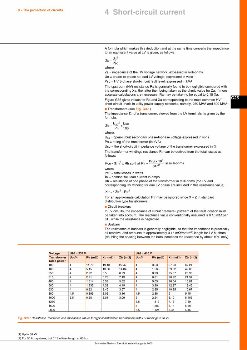
Schneider Electric - Electrical installation guide 2005
G25
G - The protection of circuits 4 Short-circuit current
A formula which makes this deduction and at the same time converts the impedanceto an equivalent value at LV is given, as follows:
ZsUPsc
= 02
whereZs = impedance of the HV voltage network, expessed in milli-ohmsUo = phase-to-phase no-load LV voltage, expressed in voltsPsc = HV 3-phase short-circuit fault level, expressed in kVA
The upstream (HV) resistance Ra is generally found to be negligible compared withthe corresponding Xa, the latter then being taken as the ohmic value for Za. If moreaccurate calculations are necessary, Ra may be taken to be equal to 0.15 Xa.
Figure G36 gives values for Ra and Xa corresponding to the most common HV(1)
short-circuit levels in utility power-supply networks, namely, 250 MVA and 500 MVA.
c Transformers (see Fig. G37 )The impedance Ztr of a transformer, viewed from the LV terminals, is given by theformula:
ZtrUPn
xUsc
= 202
100where:U20 = open-circuit secondary phase-tophase voltage expressed in voltsPn = rating of the transformer (in kVA)Usc = the short-circuit impedance voltage of the transformer expressed in %
The transformer windings resistance Rtr can be derived from the total losses asfollows:
Pcu nPcu
n= =3
32
2II
x Rtr so that Rtr x 103
in milli-ohms
wherePcu = total losses in wattsIn = nominal full-load current in ampsRtr = resistance of one phase of the transformer in milli-ohms (the LV andcorresponding HV winding for one LV phase are included in this resistance value).
Xtr Ztr Rtr= −2 2
For an approximate calculation Rtr may be ignored since X ≈ Z in standarddistribution type transformers.
c Circuit breakersIn LV circuits, the impedance of circuit breakers upstream of the fault location mustbe taken into account. The reactance value conventionally assumed is 0.15 mΩ perCB, while the resistance is neglected.
c BusbarsThe resistance of busbars is generally negligible, so that the impedance is practicallyall reactive, and amounts to approximately 0.15 mΩ/metre(2) length for LV busbars(doubling the spacing between the bars increases the reactance by about 10% only).
(1) Up to 36 kV(2) For 50 Hz systems, but 0.18 mW/m length at 60 Hz
Voltage U20 = 237 V U20 = 410 VTransformer Ucc% Rtr (mΩ) Xtr (mΩ) Ztr (mΩ) Ucc% Rtr (mΩ) Xtr (mΩ) Ztr (mΩ)rated power100 4 11.79 19.13 22.47 4 35.3 57.23 67.24160 4 5.15 13.06 14.04 4 15.63 39.02 42.03250 4 2.92 8.5 8.99 4 8.93 25.37 26.90315 4 2.21 6.78 7.13 4 6.81 20.22 21.34400 4 1.614 5.38 5.62 4 5.03 16.04 16.81500 4 1.235 4.32 4.49 4 3.90 12.87 13.45630 4 0.92 3.45 3.57 4 2.95 10.25 10.67800 4.5 0.895 3.03 3.16 4.5 2.88 9 9.451000 5.5 0.68 3.01 3.09 5 2.24 8.10 8.4051250 5.5 1.813 7.16 7.391600 6 1.389 6.14 6.302000 6.5 1.124 5.34 5.46
Fig. G37 : Resistance, reactance and impedance values for typical distribution transformers with HV windings i 20 kV
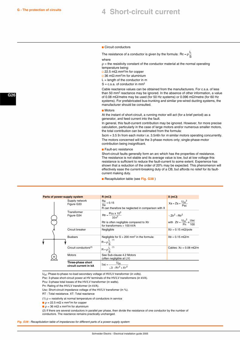
Schneider Electric - Electrical installation guide 2005
G26
G - The protection of circuits
c Circuit conductors
The resistance of a conductor is given by the formula: RcLS
= ρ
whereρ = the resistivity constant of the conductor material at the normal operatingtemperature being:v 22.5 mΩ.mm2/m for copperv 36 mΩ.mm2/m for aluminiumL = length of the conductor in mS = c.s.a. of conductor in mm2
Cable reactance values can be obtained from the manufacturers. For c.s.a. of lessthan 50 mm2 reactance may be ignored. In the absence of other information, a valueof 0.08 mΩ/metre may be used (for 50 Hz systems) or 0.096 mΩ/metre (for 60 Hzsystems). For prefabricated bus-trunking and similar pre-wired ducting systems, themanufacturer should be consulted.
c MotorsAt the instant of short-circuit, a running motor will act (for a brief period) as agenerator, and feed current into the fault.In general, this fault-current contribution may be ignored. However, for more precisecalculation, particularly in the case of large motors and/or numerous smaller motors,the total contribution can be estimated from the formula:Iscm = 3.5 In from each motor i.e. 3.5mIn for m similar motors operating concurrently.The motors concerned will be the 3-phase motors only; single-phase-motorcontribution being insignificant.
c Fault-arc resistanceShort-circuit faults generally form an arc which has the properties of resistance.The resistance is not stable and its average value is low, but at low voltage thisresistance is sufficient to reduce the fault-current to some extent. Experience hasshown that a reduction of the order of 20% may be expected. This phenomenon willeffectively ease the current-breaking duty of a CB, but affords no relief for its fault-current making duty.
c Recapitulation table (see Fig. G38 )
Fig. G38 : Recapitulation table of impedances for different parts of a power-supply system
U20: Phase-to-phase no-load secondary voltage of HV/LV transformer (in volts).Psc: 3-phase short-circuit power at HV terminals of the HV/LV transformers (in kVA).Pcu: 3-phase total losses of the HV/LV transformer (in watts).Pn: Rating of the HV/LV transformer (in kVA).Usc: Short-circuit impedance voltage of the HV/LV transfomer (in %).RT : Total resistance. XT: Total reactance
(1) ρ = resistivity at normal temperature of conductors in servicec ρ = 22.5 mΩ x mm2/m for copperc ρ = 36 mΩ x mm2/m for aluminium
(2) If there are several conductors in parallel per phase, then divide the resistance of one conductor by the number ofconductors. The reactance remains practically unchanged.
Parts of power-supply system R (mΩ) X (mΩ)Supply networkFigure G33
R can therefore be neglected in comparison with XTransformerFigure G34
Rtr is often negligible compared to Xtr withfor transformers > 100 kVA
Circuit breaker Negligible XD = 0.15 mΩ/pole
Busbars Negligible for S > 200 mm2 in the formula: XB = 0.15 mΩ/m (1)
Circuit conductors(2) (1) Cables: Xc = 0.08 mΩ/m
Motors See Sub-clause 4.2 Motors(often negligible at LV)
Three-phase shortcircuit current in kA
Xa ZaUPsc
= = 202Ra
Xa= 0.15
IscU
R XT T
=+
202 23
M
Pcu
n=
3 2IRtr
x 103
Ztr Rtr−2 2
ZtrUPn
xUsc
= 202
100
RLS
= ρ
RLS
= ρ
4 Short-circuit current
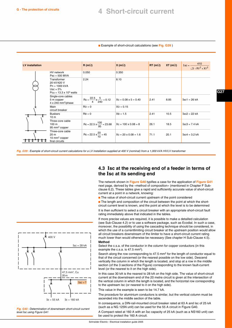
Schneider Electric - Electrical installation guide 2005
G27
G - The protection of circuits 4 Short-circuit current
Fig. G39 : Example of short-circuit current calculations for a LV installation supplied at 400 V (nominal) from a 1,000 kVA HV/LV transformer
c Example of short-circuit calculations (see Fig. G39 )
LV installation R (mΩ) X (mΩ) RT (mΩ) XT (mΩ)
HV network 0.050 0.350Psc = 500 MVATransformer 2.24 8.1020 kV/420 VPn = 1000 kVAUsc = 5%Pcu = 13.3 x 10³ wattsSingle-core cables5 m copper Xc = 0.08 x 5 = 0.40 2.41 8.85 Isc1 = 26 kA4 x 240 mm2/phaseMain RD = 0 XD = 0.15circuit breakerBusbars RB = 0 XB = 1.5 2.41 10.5 Isc2 = 22 kA10 mThree-core cable100 m Xc = 100 x 0.08 = 8 26.1 18.5 Isc3 = 7.4 kA95 mm2 copperThree-core cable20 m Xc = 20 x 0.08 = 1.6 71.1 20.1 Isc4 = 3.2 kA10 mm2 copperfinal circuits
IscR XT T
=+
410
3 2 2
Rc x= =22.5
40.12
5240
Rc x= =22.5 2 .6810095
3
Rc x= =22.5 2010
45
4.3 Isc at the receiving end of a feeder in terms ofthe Isc at its sending end
The network shown in Figure G40 typifies a case for the application of Figure G41next page, derived by the «method of composition» (mentioned in Chapter F Sub-clause 6.2). These tables give a rapid and sufficiently accurate value of short-circuitcurrent at a point in a network, knowing:c The value of short-circuit current upstream of the point consideredc The length and composition of the circuit between the point at which the short-circuit current level is known, and the point at which the level is to be determined
It is then sufficient to select a circuit breaker with an appropriate short-circuit faultrating immediately above that indicated in the tables.
If more precise values are required, it is possible to make a detailled calculation(see Sub-Clause 4.2) or to use a software package, such as Ecodial. In such a case,moreover, the possibility of using the cascading technique should be considered, inwhich the use of a currentlimiting circuit breaker at the upstream position would allowall circuit breakers downstream of the limiter to have a short-circuit current ratingmuch lower than would otherwise be necessary (See chapter H Sub-Clause 4.5).MethodSelect the c.s.a. of the conductor in the column for copper conductors (in thisexample the c.s.a. is 47.5 mm2).Search along the row corresponding to 47.5 mm2 for the length of conductor equal tothat of the circuit concerned (or the nearest possible on the low side). Descendvertically the column in which the length is located, and stop at a row in the middlesection (of the 3 sections of the Figure) corresponding to the known fault-currentlevel (or the nearest to it on the high side).
In this case 30 kA is the nearest to 28 kA on the high side. The value of short-circuitcurrent at the downstream end of the 20 metre circuit is given at the intersection ofthe vertical column in which the length is located, and the horizontal row correspondingto the upstream Isc (or nearest to it on the high side).
This value in the example is seen to be 14.7 kA.
The procedure for aluminium conductors is similar, but the vertical column must beascended into the middle section of the table.
In consequence, a DIN-rail-mounted circuit breaker rated at 63 A and Isc of 25 kA(such as a NG 125N unit) can be used for the 55 A circuit in Figure G40.
A Compact rated at 160 A with an Isc capacity of 25 kA (such as a NS160 unit) canbe used to protect the 160 A circuit.
Fig. G40 : Determination of downstream short-circuit currentlevel Isc using Figure G41
400 V
Isc = 28 kA
IB = 55 kA IB = 160 kA
47,5 mm2, Cu20 m
Isc = ?
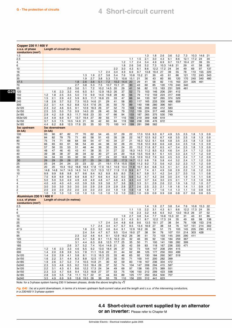
Schneider Electric - Electrical installation guide 2005
G28
G - The protection of circuits 4 Short-circuit current
Fig. G40 : Isc at a point downstream, in terms of a known upstream fault-current value and the length and c.s.a. of the intervening conductors,in a 230/400 V 3-phase system
Note: for a 3-phase system having 230 V between phases, divide the above lengths by e
4.4 Short-circuit current supplied by an alternatoror an inverter: Please refer to Chapter M
Copper 230 V / 400 Vc.s.a. of phase Length of circuit (in metres)conductors (mm2)1.5 1.3 1.8 2.6 3.6 5.2 7.3 10.3 14.6 212.5 1.1 1.5 2.1 3.0 4.3 6.1 8.6 12.1 17.2 24 344 1.2 1.7 2.4 3.4 4.9 6.9 9.7 13.7 19.4 27 39 556 1.8 2.6 3.6 5.2 7.3 10.3 14.6 21 29 41 58 8210 2.2 3.0 4.3 6.1 8.6 12.2 17.2 24 34 49 69 97 13716 1.7 2.4 3.4 4.9 6.9 9.7 13.8 19.4 27 39 55 78 110 155 22025 1.3 1.9 2.7 3.8 5.4 7.6 10.8 15.2 21 30 43 61 86 121 172 243 34335 1.9 2.7 3.8 5.3 7.5 10.6 15.1 21 30 43 60 85 120 170 240 340 48047.5 1.8 2.6 3.6 5.1 7.2 10.2 14.4 20 29 41 58 82 115 163 231 326 46170 2.7 3.8 5.3 7.5 10.7 15.1 21 30 43 60 85 120 170 240 34095 2.6 3.6 5.1 7.2 10.2 14.5 20 29 41 58 82 115 163 231 326 461120 1.6 2.3 3.2 4.6 6.5 9.1 12.9 18.3 26 37 52 73 103 146 206 291 412150 1.2 1.8 2.5 3.5 5.0 7.0 9.9 14.0 19.8 28 40 56 79 112 159 224 317 448185 1.5 2.1 2.9 4.2 5.9 8.3 11.7 16.6 23 33 47 66 94 133 187 265 374 529240 1.8 2.6 3.7 5.2 7.3 10.3 14.6 21 29 41 58 83 117 165 233 330 466 659300 2.2 3.1 4.4 6.2 8.8 12.4 17.6 25 35 50 70 99 140 198 280 396 5612x120 2.3 3.2 4.6 6.5 9.1 12.9 18.3 26 37 52 73 103 146 206 292 412 5832x150 2.5 3.5 5.0 7.0 9.9 14.0 20 28 40 56 79 112 159 224 317 448 6342x185 2.9 4.2 5.9 8.3 11.7 16.6 23 33 47 66 94 133 187 265 375 530 749553x120 3.4 4.9 6.9 9.7 13.7 19.4 27 39 55 77 110 155 219 309 438 6193x150 3.7 5.3 7.5 10.5 14.9 21 30 42 60 84 119 168 238 336 476 6723x185 4.4 6.2 8.8 12.5 17.6 25 35 50 70 100 141 199 281 398 562Isc upstream Isc downstream(in kA) (in kA)100 93 90 87 82 77 70 62 54 45 37 29 22 17.0 12.6 9.3 6.7 4.9 3.5 2.5 1.8 1.3 0.990 84 82 79 75 71 65 58 51 43 35 28 22 16.7 12.5 9.2 6.7 4.8 3.5 2.5 1.8 1.3 0.980 75 74 71 68 64 59 54 47 40 34 27 21 16.3 12.2 9.1 6.6 4.8 3.5 2.5 1.8 1.3 0.970 66 65 63 61 58 54 49 44 38 32 26 20 15.8 12.0 8.9 6.6 4.8 3.4 2.5 1.8 1.3 0.960 57 56 55 53 51 48 44 39 35 29 24 20 15.2 11.6 8.7 6.5 4.7 3.4 2.5 1.8 1.3 0.950 48 47 46 45 43 41 38 35 31 27 22 18.3 14.5 11.2 8.5 6.3 4.6 3.4 2.4 1.7 1.2 0.940 39 38 38 37 36 34 32 30 27 24 20 16.8 13.5 10.6 8.1 6.1 4.5 3.3 2.4 1.7 1.2 0.935 34 34 33 33 32 30 29 27 24 22 18.8 15.8 12.9 10.2 7.9 6.0 4.5 3.3 2.4 1.7 1.2 0.930 29 29 29 28 27 27 25 24 22 20 17.3 14.7 12.2 9.8 7.6 5.8 4.4 3.2 2.4 1.7 1.2 0.925 25 24 24 24 23 23 22 21 19.1 17.4 15.5 13.4 11.2 9.2 7.3 5.6 4.2 3.2 2.3 1.7 1.2 0.920 20 20 19.4 19.2 18.8 18.4 17.8 17.0 16.1 14.9 13.4 11.8 10.1 8.4 6.8 5.3 4.1 3.1 2.3 1.7 1.2 0.915 14.8 14.8 14.7 14.5 14.3 14.1 13.7 13.3 12.7 11.9 11.0 9.9 8.7 7.4 6.1 4.9 3.8 2.9 2.2 1.6 1.2 0.910 9.9 9.9 9.8 9.8 9.7 9.6 9.4 9.2 8.9 8.5 8.0 7.4 6.7 5.9 5.1 4.2 3.4 2.7 2.0 1.5 1.1 0.87 7.0 6.9 6.9 6.9 6.9 6.8 6.7 6.6 6.4 6.2 6.0 5.6 5.2 4.7 4.2 3.6 3.0 2.4 1.9 1.4 1.1 0.85 5.0 5.0 5.0 4.9 4.9 4.9 4.9 4.8 4.7 4.6 4.5 4.3 4.0 3.7 3.4 3.0 2.5 2.1 1.7 1.3 1.0 0.84 4.0 4.0 4.0 4.0 4.0 3.9 3.9 3.9 3.8 3.7 3.6 3.5 3.3 3.1 2.9 2.6 2.2 1.9 1.6 1.2 1.0 0.73 3.0 3.0 3.0 3.0 3.0 3.0 2.9 2.9 2.9 2.9 2.8 2.7 2.6 2.5 2.3 2.1 1.9 1.6 1.4 1.1 0.9 0.72 2.0 2.0 2.0 2.0 2.0 2.0 2.0 2.0 2.0 1.9 1.9 1.9 1.8 1.8 1.7 1.6 1.4 1.3 1.1 1.0 0.8 0.61 1.0 1.0 1.0 1.0 1.0 1.0 1.0 1.0 1.0 1.0 1.0 1.0 1.0 0.9 0.9 0.9 0.8 0.8 0.7 0.6 0.6 0.5Aluminium 230 V / 400 Vc.s.a. of phase Length of circuit (in metres)conductors (mm2)2.5 1.4 1.9 2.7 3.8 5.4 7.6 10.8 15.3 224 1.1 1.5 2.2 3.1 4.3 6.1 8.6 12.2 17.3 24 356 1.6 2.3 3.2 4.6 6.5 9.2 13.0 18.3 26 37 5210 1.9 2.7 3.8 5.4 7.7 10.8 15.3 22 31 43 61 8616 2.2 3.1 4.3 6.1 8.7 12.2 17.3 24 35 49 69 98 13825 1.7 2.4 3.4 4.8 6.8 9.6 13.5 19.1 27 38 54 76 108 153 21635 1.7 2.4 3.4 4.7 6.7 9.5 13.4 18.9 27 38 54 76 107 151 214 30247.5 1.6 2.3 3.2 4.6 6.4 9.1 12.9 18.2 26 36 51 73 103 145 205 290 41070 2.4 3.4 4.7 6.7 9.5 13.4 19.0 27 38 54 76 107 151 214 303 42895 2.3 3.2 4.6 6.4 9.1 12.9 18.2 26 36 51 73 103 145 205 290 411120 2.9 4.1 5.8 8.1 11.5 16.3 23 32 46 65 92 130 184 259 367150 3.1 4.4 6.3 8.8 12.5 17.7 25 35 50 71 100 141 199 282 399185 2.6 3.7 5.2 7.4 10.4 14.8 21 30 42 59 83 118 167 236 333 471240 1.2 1.6 2.3 3.3 4.6 6.5 9.2 13.0 18.4 26 37 52 73 104 147 208 294 415300 1.4 2.0 2.8 3.9 5.5 7.8 11.1 15.6 22 31 44 62 88 125 177 250 353 4992x120 1.4 2.0 2.9 4.1 5.8 8.1 11.5 16.3 23 33 46 65 92 130 184 260 367 5192x150 1.6 2.2 3.1 4.4 6.3 8.8 12.5 17.7 25 35 50 71 100 141 200 282 3992x185 1.9 2.6 3.7 5.2 7.4 10.5 14.8 21 30 42 59 83 118 167 236 334 4722x240 2.3 3.3 4.6 6.5 9.2 13.0 18.4 26 37 52 74 104 147 208 294 415 5873x120 2.2 3.1 4.3 6.1 8.6 12.2 17.3 24 34 49 69 97 138 195 275 389 5513x150 2.3 3.3 4.7 6.6 9.4 13.3 18.8 27 37 53 75 106 150 212 299 423 5983x185 2.8 3.9 5.5 7.8 11.1 15.7 22 31 44 63 89 125 177 250 354 500 7073x240 3.5 4.9 6.9 9.8 13.8 19.5 28 39 55 78 110 156 220 312 441 623
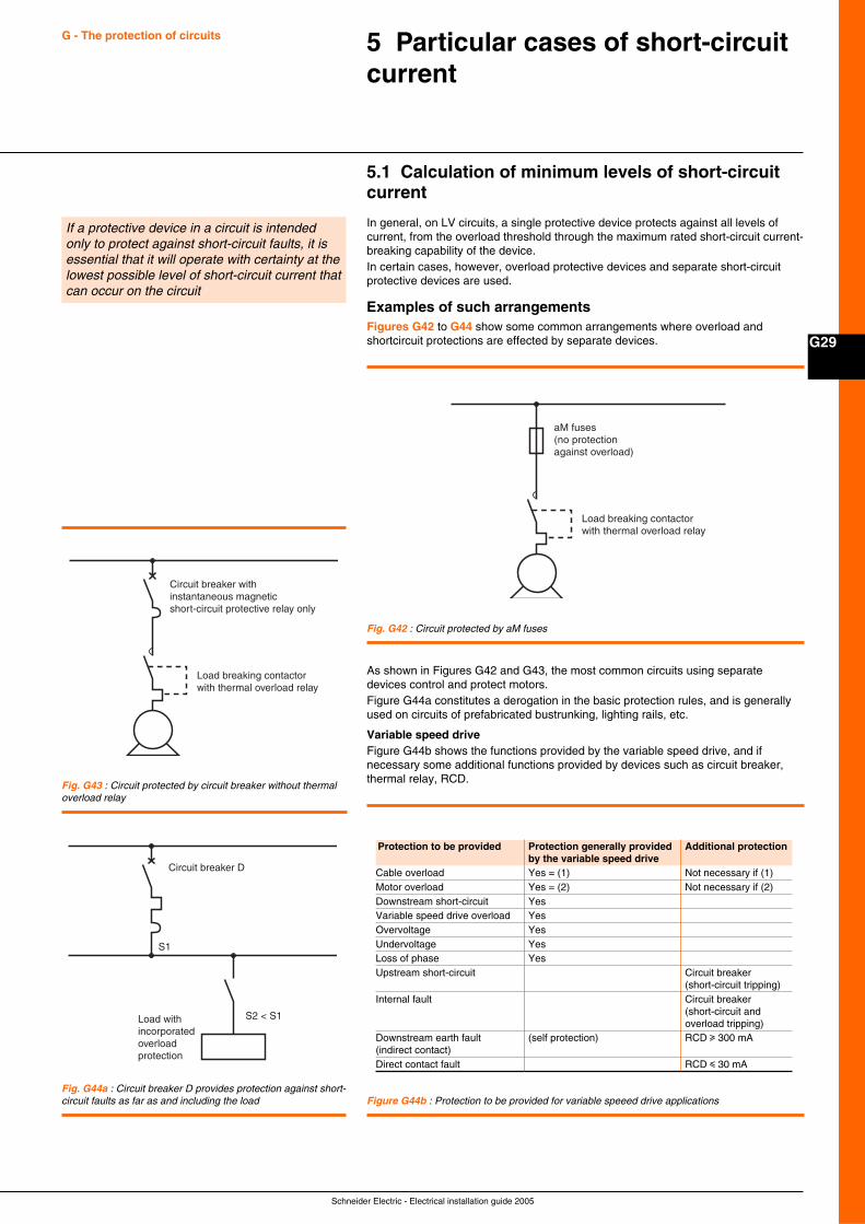
Schneider Electric - Electrical installation guide 2005
G29
G - The protection of circuits 5 Particular cases of short-circuitcurrent
5.1 Calculation of minimum levels of short-circuitcurrent
In general, on LV circuits, a single protective device protects against all levels ofcurrent, from the overload threshold through the maximum rated short-circuit current-breaking capability of the device.In certain cases, however, overload protective devices and separate short-circuitprotective devices are used.
Examples of such arrangementsFigures G42 to G44 show some common arrangements where overload andshortcircuit protections are effected by separate devices.
If a protective device in a circuit is intendedonly to protect against short-circuit faults, it isessential that it will operate with certainty at thelowest possible level of short-circuit current thatcan occur on the circuit
aM fuses (no protection against overload)
Load breaking contactorwith thermal overload relay
Circuit breaker withinstantaneous magneticshort-circuit protective relay only
Load breaking contactorwith thermal overload relay
Circuit breaker D
Load withincorporatedoverloadprotection
S1
S2 < S1
Fig. G44a : Circuit breaker D provides protection against short-circuit faults as far as and including the load
Fig. G42 : Circuit protected by aM fuses
Fig. G43 : Circuit protected by circuit breaker without thermaloverload relay
Protection to be provided Protection generally provided Additional protectionby the variable speed drive
Cable overload Yes = (1) Not necessary if (1)Motor overload Yes = (2) Not necessary if (2)Downstream short-circuit YesVariable speed drive overload YesOvervoltage YesUndervoltage YesLoss of phase YesUpstream short-circuit Circuit breaker
(short-circuit tripping)Internal fault Circuit breaker
(short-circuit andoverload tripping)
Downstream earth fault (self protection) RCD u 300 mA(indirect contact)Direct contact fault RCD i 30 mA
Figure G44b : Protection to be provided for variable speeed drive applications
As shown in Figures G42 and G43, the most common circuits using separatedevices control and protect motors.Figure G44a constitutes a derogation in the basic protection rules, and is generallyused on circuits of prefabricated bustrunking, lighting rails, etc.
Variable speed driveFigure G44b shows the functions provided by the variable speed drive, and ifnecessary some additional functions provided by devices such as circuit breaker,thermal relay, RCD.
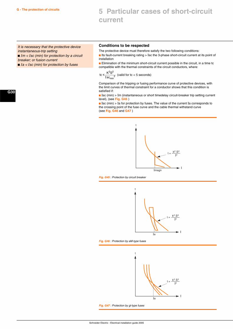
Schneider Electric - Electrical installation guide 2005
G30
G - The protection of circuits
Conditions to be respectedThe protective device must therefore satisfy the two following conditions:c Its fault-current breaking rating > Isc the 3-phase short-circuit current at its point ofinstallationc Elimination of the minimum short-circuit current possible in the circuit, in a time tccompatible with the thermal constraints of the circuit conductors, where:
tcK Ssc
min
i
2 2
2I (valid for tc < 5 seconds)
Comparison of the tripping or fusing performance curve of protective devices, withthe limit curves of thermal constraint for a conductor shows that this condition issatisfied if:c Isc (min) > Im (instantaneous or short timedelay circuit-breaker trip setting currentlevel), (see Fig. G45 )c Isc (min) > Ia for protection by fuses. The value of the current Ia corresponds tothe crossing point of the fuse curve and the cable thermal withstand curve(see Fig. G46 and G47 )
It is necessary that the protective deviceinstantaneous-trip settingc Im < Isc (min) for protection by a circuitbreaker; or fusion currentc Ia < Isc (min) for protection by fuses
Fig. G47 : Protection by gl-type fuses
I
t
Imagn
t = k2 S2
I2
I
t
Ia
t = k2 S2
I2
Fig. G45 : Protection by circuit breaker
I
t
Ia
t = k2 S2
I2
Fig. G46 : Protection by aM-type fuses
5 Particular cases of short-circuitcurrent
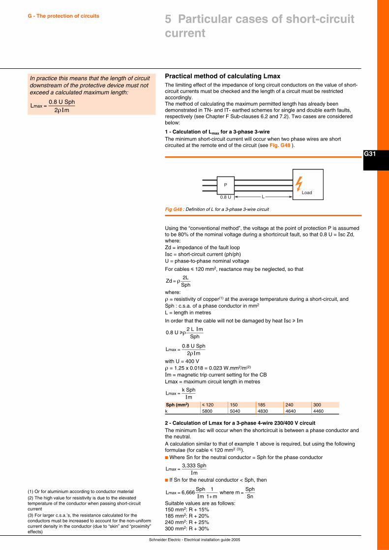
Schneider Electric - Electrical installation guide 2005
G31
G - The protection of circuits 5 Particular cases of short-circuitcurrent
Practical method of calculating LmaxThe limiting effect of the impedance of long circuit conductors on the value of short-circuit currents must be checked and the length of a circuit must be restrictedaccordingly.The method of calculating the maximum permitted length has already beendemonstrated in TN- and IT- earthed schemes for single and double earth faults,respectively (see Chapter F Sub-clauses 6.2 and 7.2). Two cases are consideredbelow:
1 - Calculation of Lmax for a 3-phase 3-wireThe minimum short-circuit current will occur when two phase wires are shortcircuited at the remote end of the circuit (see Fig. G48 ).
In practice this means that the length of circuitdownstream of the protective device must notexceed a calculated maximum length:
L0.8 U Sph
2 mmax =
ρI
Load
P
0.8 U L
Using the “conventional method”, the voltage at the point of protection P is assumedto be 80% of the nominal voltage during a shortcircuit fault, so that 0.8 U = Isc Zd,where:Zd = impedance of the fault loopIsc = short-circuit current (ph/ph)U = phase-to-phase nominal voltage
For cables i 120 mm2, reactance may be neglected, so that
Zd2L
= ρSph
where:ρ = resistivity of copper(1) at the average temperature during a short-circuit, andSph : c.s.a. of a phase conductor in mm2
L = length in metres
In order that the cable will not be damaged by heat Isc u Im
0.8 U 2 L m
Sphuρ
I
L0.8 U Sph
2 mmax =
ρIwith U = 400 Vρ = 1.25 x 0.018 = 0.023 W.mm2/m(2)
Im = magnetic trip current setting for the CBLmax = maximum circuit length in metres
Lk Sph
mmax =
I
Fig G48 : Definition of L for a 3-phase 3-wire circuit
Sph (mm2) i 120 150 185 240 300k 5800 5040 4830 4640 4460
(1) Or for aluminium according to conductor material(2) The high value for resistivity is due to the elevatedtemperature of the conductor when passing short-circuitcurrent(3) For larger c.s.a.’s, the resistance calculated for theconductors must be increased to account for the non-uniformcurrent density in the conductor (due to “skin” and “proximity”effects)
2 - Calculation of Lmax for a 3-phase 4-wire 230/400 V circuitThe minimum Isc will occur when the shortcircuit is between a phase conductor andthe neutral.A calculation similar to that of example 1 above is required, but using the followingformulae (for cable i 120 mm2 (3)).c Where Sn for the neutral conductor = Sph for the phase conductor
L3,333 Sph
mmax =
Ic If Sn for the neutral conductor < Sph, then
L 6,666Sph
m where max =
+=
I1
1 mm
SphSn
Suitable values are as follows:150 mm2: R + 15%185 mm2: R + 20%240 mm2: R + 25%300 mm2: R + 30%
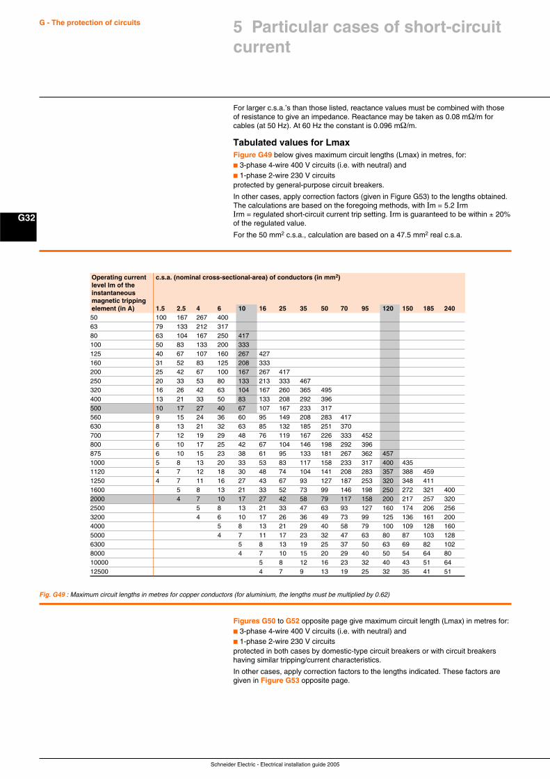
Schneider Electric - Electrical installation guide 2005
G32
G - The protection of circuits
For larger c.s.a.’s than those listed, reactance values must be combined with thoseof resistance to give an impedance. Reactance may be taken as 0.08 mΩ/m forcables (at 50 Hz). At 60 Hz the constant is 0.096 mΩ/m.
Tabulated values for LmaxFigure G49 below gives maximum circuit lengths (Lmax) in metres, for:c 3-phase 4-wire 400 V circuits (i.e. with neutral) andc 1-phase 2-wire 230 V circuitsprotected by general-purpose circuit breakers.
In other cases, apply correction factors (given in Figure G53) to the lengths obtained.The calculations are based on the foregoing methods, with Im = 5.2 IrmIrm = regulated short-circuit current trip setting. Irm is guaranteed to be within ± 20%of the regulated value.
For the 50 mm2 c.s.a., calculation are based on a 47.5 mm2 real c.s.a.
Fig. G49 : Maximum circuit lengths in metres for copper conductors (for aluminium, the lengths must be multiplied by 0.62)
Operating current c.s.a. (nominal cross-sectional-area) of conductors (in mm2)level Im of theinstantaneousmagnetic trippingelement (in A) 1.5 2.5 4 6 10 16 25 35 50 70 95 120 150 185 24050 100 167 267 40063 79 133 212 31780 63 104 167 250 417100 50 83 133 200 333125 40 67 107 160 267 427160 31 52 83 125 208 333200 25 42 67 100 167 267 417250 20 33 53 80 133 213 333 467320 16 26 42 63 104 167 260 365 495400 13 21 33 50 83 133 208 292 396500 10 17 27 40 67 107 167 233 317560 9 15 24 36 60 95 149 208 283 417630 8 13 21 32 63 85 132 185 251 370700 7 12 19 29 48 76 119 167 226 333 452800 6 10 17 25 42 67 104 146 198 292 396875 6 10 15 23 38 61 95 133 181 267 362 4571000 5 8 13 20 33 53 83 117 158 233 317 400 4351120 4 7 12 18 30 48 74 104 141 208 283 357 388 4591250 4 7 11 16 27 43 67 93 127 187 253 320 348 4111600 5 8 13 21 33 52 73 99 146 198 250 272 321 4002000 4 7 10 17 27 42 58 79 117 158 200 217 257 3202500 5 8 13 21 33 47 63 93 127 160 174 206 2563200 4 6 10 17 26 36 49 73 99 125 136 161 2004000 5 8 13 21 29 40 58 79 100 109 128 1605000 4 7 11 17 23 32 47 63 80 87 103 1286300 5 8 13 19 25 37 50 63 69 82 1028000 4 7 10 15 20 29 40 50 54 64 8010000 5 8 12 16 23 32 40 43 51 6412500 4 7 9 13 19 25 32 35 41 51
Figures G50 to G52 opposite page give maximum circuit length (Lmax) in metres for:c 3-phase 4-wire 400 V circuits (i.e. with neutral) andc 1-phase 2-wire 230 V circuitsprotected in both cases by domestic-type circuit breakers or with circuit breakershaving similar tripping/current characteristics.
In other cases, apply correction factors to the lengths indicated. These factors aregiven in Figure G53 opposite page.
5 Particular cases of short-circuitcurrent
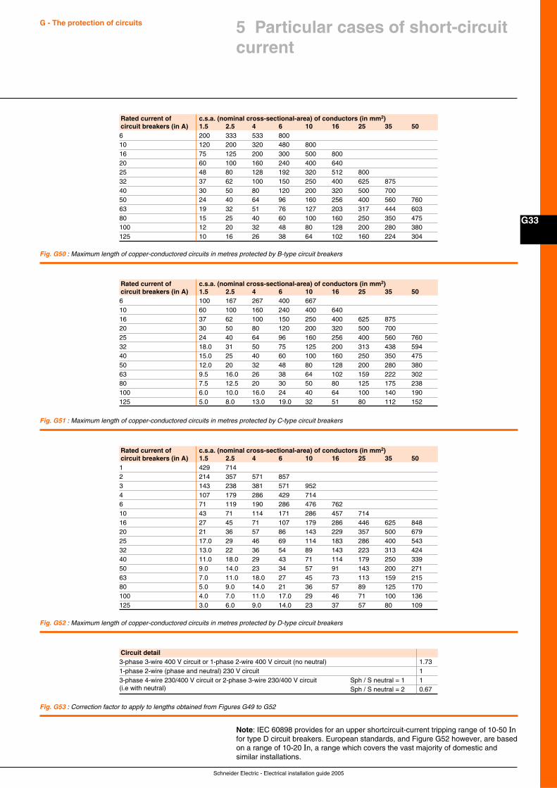
Schneider Electric - Electrical installation guide 2005
G33
G - The protection of circuits 5 Particular cases of short-circuitcurrent
Fig. G52 : Maximum length of copper-conductored circuits in metres protected by D-type circuit breakers
Fig. G50 : Maximum length of copper-conductored circuits in metres protected by B-type circuit breakers
Fig. G51 : Maximum length of copper-conductored circuits in metres protected by C-type circuit breakers
Fig. G53 : Correction factor to apply to lengths obtained from Figures G49 to G52
Circuit detail3-phase 3-wire 400 V circuit or 1-phase 2-wire 400 V circuit (no neutral) 1.731-phase 2-wire (phase and neutral) 230 V circuit 13-phase 4-wire 230/400 V circuit or 2-phase 3-wire 230/400 V circuit Sph / S neutral = 1 1(i.e with neutral) Sph / S neutral = 2 0.67
Note: IEC 60898 provides for an upper shortcircuit-current tripping range of 10-50 Infor type D circuit breakers. European standards, and Figure G52 however, are basedon a range of 10-20 In, a range which covers the vast majority of domestic andsimilar installations.
Rated current of c.s.a. (nominal cross-sectional-area) of conductors (in mm2)circuit breakers (in A) 1.5 2.5 4 6 10 16 25 35 506 200 333 533 80010 120 200 320 480 80016 75 125 200 300 500 80020 60 100 160 240 400 64025 48 80 128 192 320 512 80032 37 62 100 150 250 400 625 87540 30 50 80 120 200 320 500 70050 24 40 64 96 160 256 400 560 76063 19 32 51 76 127 203 317 444 60380 15 25 40 60 100 160 250 350 475100 12 20 32 48 80 128 200 280 380125 10 16 26 38 64 102 160 224 304
Rated current of c.s.a. (nominal cross-sectional-area) of conductors (in mm2)circuit breakers (in A) 1.5 2.5 4 6 10 16 25 35 506 100 167 267 400 66710 60 100 160 240 400 64016 37 62 100 150 250 400 625 87520 30 50 80 120 200 320 500 70025 24 40 64 96 160 256 400 560 76032 18.0 31 50 75 125 200 313 438 59440 15.0 25 40 60 100 160 250 350 47550 12.0 20 32 48 80 128 200 280 38063 9.5 16.0 26 38 64 102 159 222 30280 7.5 12.5 20 30 50 80 125 175 238100 6.0 10.0 16.0 24 40 64 100 140 190125 5.0 8.0 13.0 19.0 32 51 80 112 152
Rated current of c.s.a. (nominal cross-sectional-area) of conductors (in mm2)circuit breakers (in A) 1.5 2.5 4 6 10 16 25 35 501 429 7142 214 357 571 8573 143 238 381 571 9524 107 179 286 429 7146 71 119 190 286 476 76210 43 71 114 171 286 457 71416 27 45 71 107 179 286 446 625 84820 21 36 57 86 143 229 357 500 67925 17.0 29 46 69 114 183 286 400 54332 13.0 22 36 54 89 143 223 313 42440 11.0 18.0 29 43 71 114 179 250 33950 9.0 14.0 23 34 57 91 143 200 27163 7.0 11.0 18.0 27 45 73 113 159 21580 5.0 9.0 14.0 21 36 57 89 125 170100 4.0 7.0 11.0 17.0 29 46 71 100 136125 3.0 6.0 9.0 14.0 23 37 57 80 109
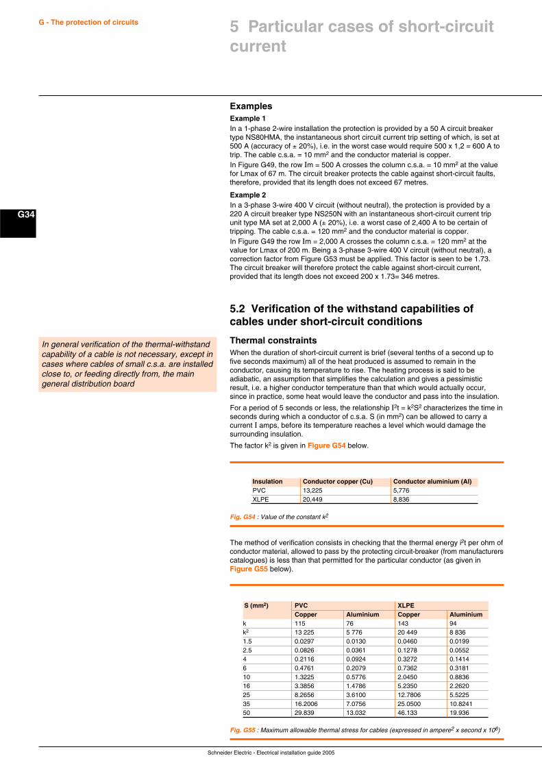
Schneider Electric - Electrical installation guide 2005
G34
G - The protection of circuits
ExamplesExample 1In a 1-phase 2-wire installation the protection is provided by a 50 A circuit breakertype NS80HMA, the instantaneous short circuit current trip setting of which, is set at500 A (accuracy of ± 20%), i.e. in the worst case would require 500 x 1,2 = 600 A totrip. The cable c.s.a. = 10 mm2 and the conductor material is copper.In Figure G49, the row Im = 500 A crosses the column c.s.a. = 10 mm2 at the valuefor Lmax of 67 m. The circuit breaker protects the cable against short-circuit faults,therefore, provided that its length does not exceed 67 metres.
Example 2In a 3-phase 3-wire 400 V circuit (without neutral), the protection is provided by a220 A circuit breaker type NS250N with an instantaneous short-circuit current tripunit type MA set at 2,000 A (± 20%), i.e. a worst case of 2,400 A to be certain oftripping. The cable c.s.a. = 120 mm2 and the conductor material is copper.In Figure G49 the row Im = 2,000 A crosses the column c.s.a. = 120 mm2 at thevalue for Lmax of 200 m. Being a 3-phase 3-wire 400 V circuit (without neutral), acorrection factor from Figure G53 must be applied. This factor is seen to be 1.73.The circuit breaker will therefore protect the cable against short-circuit current,provided that its length does not exceed 200 x 1.73= 346 metres.
5.2 Verification of the withstand capabilities ofcables under short-circuit conditions
Thermal constraintsWhen the duration of short-circuit current is brief (several tenths of a second up tofive seconds maximum) all of the heat produced is assumed to remain in theconductor, causing its temperature to rise. The heating process is said to beadiabatic, an assumption that simplifies the calculation and gives a pessimisticresult, i.e. a higher conductor temperature than that which would actually occur,since in practice, some heat would leave the conductor and pass into the insulation.
For a period of 5 seconds or less, the relationship I2t = k2S2 characterizes the time inseconds during which a conductor of c.s.a. S (in mm2) can be allowed to carry acurrent I amps, before its temperature reaches a level which would damage thesurrounding insulation.
The factor k2 is given in Figure G54 below.
In general verification of the thermal-withstandcapability of a cable is not necessary, except incases where cables of small c.s.a. are installedclose to, or feeding directly from, the maingeneral distribution board
Fig. G54 : Value of the constant k2
The method of verification consists in checking that the thermal energy i2t per ohm ofconductor material, allowed to pass by the protecting circuit-breaker (from manufacturerscatalogues) is less than that permitted for the particular conductor (as given inFigure G55 below).
Fig. G55 : Maximum allowable thermal stress for cables (expressed in ampere2 x second x 106)
Insulation Conductor copper (Cu) Conductor aluminium (Al)PVC 13,225 5,776XLPE 20,449 8,836
S (mm2) PVC XLPECopper Aluminium Copper Aluminium
k 115 76 143 94k2 13 225 5 776 20 449 8 8361.5 0.0297 0.0130 0.0460 0.01992.5 0.0826 0.0361 0.1278 0.05524 0.2116 0.0924 0.3272 0.14146 0.4761 0.2079 0.7362 0.318110 1.3225 0.5776 2.0450 0.883616 3.3856 1.4786 5.2350 2.262025 8.2656 3.6100 12.7806 5.522535 16.2006 7.0756 25.0500 10.824150 29.839 13.032 46.133 19.936
5 Particular cases of short-circuitcurrent
Schneider Electric - Electrical installation guide 2005
G35
G - The protection of circuits 5 Particular cases of short-circuitcurrent
ExampleIs a copper-cored XLPE cable of 4 mm2 c.s.a. adequately protected by aC60N circuit breaker?
Figure G55 shows that the I2t value for the cable is 0.3272 x 10⁶, while the maximum“let-through” value by the circuit breaker, as given in the manufacturer’s catalogue, isconsiderably less.The cable is therefore adequately protected by the circuit breaker up to its full ratedbreaking capability.
Electrodynamic constraintsFor all type of circuit (conductors or bus-trunking), it is necessary to take intoaccount of electrodynamic effects.
To withstand the electrodynamic constraints, the conductors must be solidly fixedand the connection must me strongly tightened.
For bus-trunking and other kinds of prefabricated pre-conductored channels, rails,etc. it is also necessary to verify that the electrodynamic withstand performancewhen carrying short-circuit currents is satisfactory. The peak value of current, limitedby the circuit breaker or fuse, must be less than that for which the pre-conductoredsystem is rated. Tables of coordination ensuring adequate protection of theirproducts are generally published by the manufacturers and provide a majoradvantage of such systems.
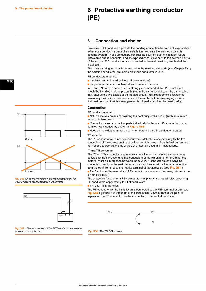
Schneider Electric - Electrical installation guide 2005
G36
G - The protection of circuits 6 Protective earthing conductor(PE)
6.1 Connection and choice
Protective (PE) conductors provide the bonding connection between all exposed andextraneous conductive parts of an installation, to create the main equipotentialbonding system. These conductors conduct fault current due to insulation failure(between a phase conductor and an exposed conductive part) to the earthed neutralof the source. P.E. conductors are connected to the main earthing terminal of theinstallation.The main earthing terminal is connected to the earthing electrode (see Chapter E) bythe earthing conductor (grounding electrode conductor in USA).
PE conductors must be:c Insulated and coloured yellow and green (stripes)c Be protected against mechanical and chemical damageIn IT and TN-earthed schemes it is strongly recommended that PE conductorsshould be installed in close proximity (i.e. in the same conduits, on the same cabletray, etc.) as the live cables of the related circuit. This arrangement ensures theminimum possible inductive reactance in the earth-fault currentcarrying circuits.It should be noted that this arrangement is originally provided by bus-trunking.
ConnectionPE conductors must:c Not include any means of breaking the continuity of the circuit (such as a switch,removable links, etc.)c Connect exposed conductive parts individually to the main PE conductor, i.e. inparallel, not in series, as shown in Figure G56c Have an individual terminal on common earthing bars in distribution boards.
TT schemeThe PE conductor need not necessarily be installed in close proximity to the liveconductors of the corresponding circuit, since high values of earth-fault current arenot needed to operate the RCD-type of protection used in TT installations.
IT and TN schemesThe PE or PEN conductor, as previously noted, must be installed as close by aspossible to the corresponding live conductors of the circuit and no ferro-magneticmaterial must be interposed between them. A PEN conductor must always beconnected directly to the earth terminal of an appliance, with a looped connectionfrom the earth terminal to the neutral terminal of the appliance (see Fig. G57 ).c TN-C scheme (the neutral and PE conductor are one and the same, referred to asa PEN conductor)The protective function of a PEN conductor has priority, so that all rules governingPE conductors apply strictly to PEN conductorsc TN-C to TN-S transitionThe PE conductor for the installlation is connected to the PEN terminal or bar (seeFig. G58 ) generally at the origin of the installation. Downstream of the point ofseparation, no PE conductor can be connected to the neutral conductor.
Fig. G57 : Direct connection of the PEN conductor to the earthterminal of an appliance
PE
PE
Correct
Incorrect
Fig. G56 : A poor connection in a series arrangement willleave all downstream appliances unprotected
Fig. G58 : The TN-C-S scheme
PEN
PEN PE
N
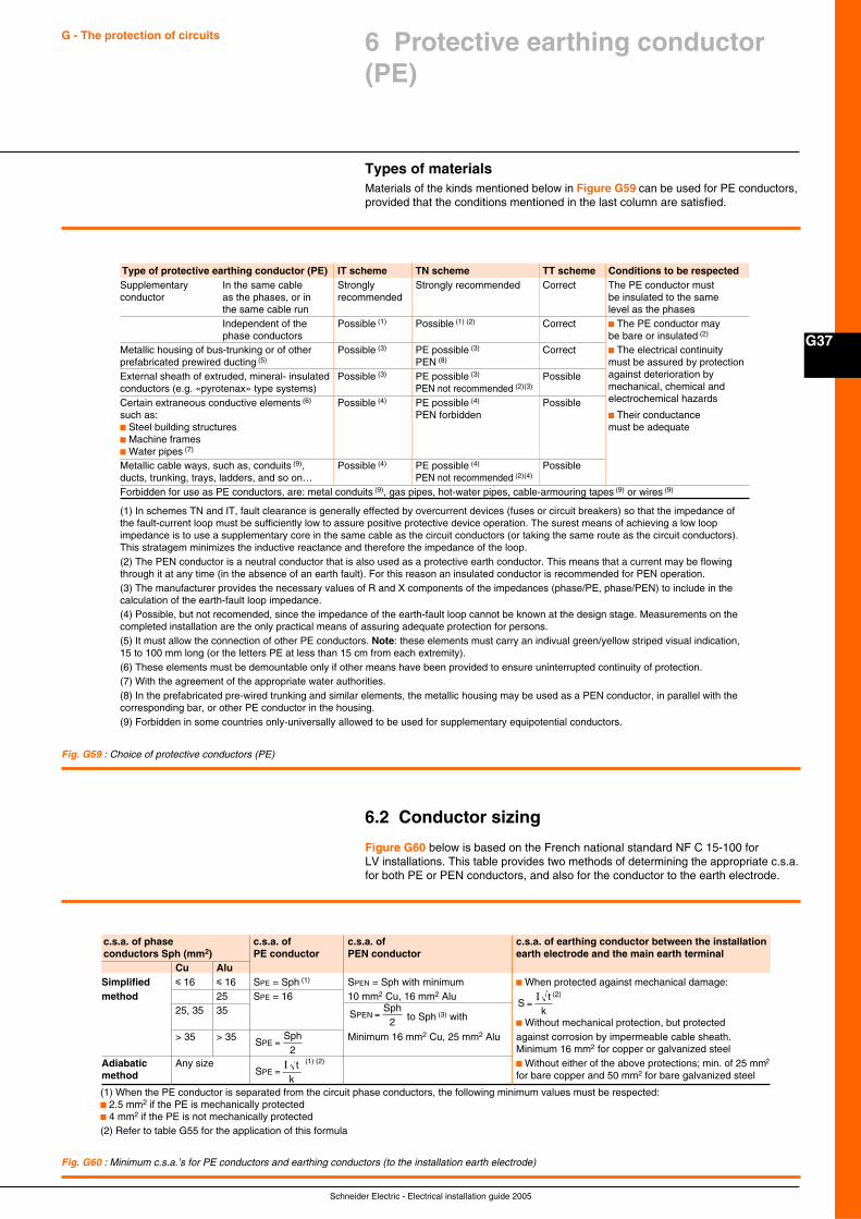
Schneider Electric - Electrical installation guide 2005
G37
G - The protection of circuits 6 Protective earthing conductor(PE)
Types of materialsMaterials of the kinds mentioned below in Figure G59 can be used for PE conductors,provided that the conditions mentioned in the last column are satisfied.
Fig. G59 : Choice of protective conductors (PE)
6.2 Conductor sizing
Figure G60 below is based on the French national standard NF C 15-100 forLV installations. This table provides two methods of determining the appropriate c.s.a.for both PE or PEN conductors, and also for the conductor to the earth electrode.
Fig. G60 : Minimum c.s.a.’s for PE conductors and earthing conductors (to the installation earth electrode)
(1) When the PE conductor is separated from the circuit phase conductors, the following minimum values must be respected:c 2.5 mm2 if the PE is mechanically protectedc 4 mm2 if the PE is not mechanically protected(2) Refer to table G55 for the application of this formula
c.s.a. of phase c.s.a. of c.s.a. of c.s.a. of earthing conductor between the installationconductors Sph (mm2) PE conductor PEN conductor earth electrode and the main earth terminal
Cu AluSimplified i 16 i 16 SPE = Sph (1) SPEN = Sph with minimum c When protected against mechanical damage:method 25 SPE = 16 10 mm2 Cu, 16 mm2 Alu (2)
25, 35 35 to Sph (3) with
c Without mechanical protection, but protected> 35 > 35 Minimum 16 mm2 Cu, 25 mm2 Alu against corrosion by impermeable cable sheath.
Minimum 16 mm2 for copper or galvanized steelAdiabatic Any size (1) (2)
c Without either of the above protections; min. of 25 mm2
method for bare copper and 50 mm2 for bare galvanized steel
SSph
PE =2
SSph
PEN =2
St
kPE =
I
St
k=I
(1) In schemes TN and IT, fault clearance is generally effected by overcurrent devices (fuses or circuit breakers) so that the impedance ofthe fault-current loop must be sufficiently low to assure positive protective device operation. The surest means of achieving a low loopimpedance is to use a supplementary core in the same cable as the circuit conductors (or taking the same route as the circuit conductors).This stratagem minimizes the inductive reactance and therefore the impedance of the loop.(2) The PEN conductor is a neutral conductor that is also used as a protective earth conductor. This means that a current may be flowingthrough it at any time (in the absence of an earth fault). For this reason an insulated conductor is recommended for PEN operation.(3) The manufacturer provides the necessary values of R and X components of the impedances (phase/PE, phase/PEN) to include in thecalculation of the earth-fault loop impedance.(4) Possible, but not recomended, since the impedance of the earth-fault loop cannot be known at the design stage. Measurements on thecompleted installation are the only practical means of assuring adequate protection for persons.(5) It must allow the connection of other PE conductors. Note: these elements must carry an indivual green/yellow striped visual indication,15 to 100 mm long (or the letters PE at less than 15 cm from each extremity).(6) These elements must be demountable only if other means have been provided to ensure uninterrupted continuity of protection.(7) With the agreement of the appropriate water authorities.(8) In the prefabricated pre-wired trunking and similar elements, the metallic housing may be used as a PEN conductor, in parallel with thecorresponding bar, or other PE conductor in the housing.(9) Forbidden in some countries only-universally allowed to be used for supplementary equipotential conductors.
Type of protective earthing conductor (PE) IT scheme TN scheme TT scheme Conditions to be respectedSupplementary In the same cable Strongly Strongly recommended Correct The PE conductor mustconductor as the phases, or in recommended be insulated to the same
the same cable run level as the phasesIndependent of the Possible (1) Possible (1) (2) Correct c The PE conductor mayphase conductors be bare or insulated (2)
Metallic housing of bus-trunking or of other Possible (3) PE possible (3) Correct c The electrical continuityprefabricated prewired ducting (5) PEN (8) must be assured by protectionExternal sheath of extruded, mineral- insulated Possible (3) PE possible (3) Possible against deterioration byconductors (e.g. «pyrotenax» type systems) PEN not recommended (2)(3) mechanical, chemical and
Certain extraneous conductive elements (6) Possible (4) PE possible (4) Possible electrochemical hazards
such as: PEN forbidden c Their conductancec Steel building structures must be adequatec Machine framesc Water pipes (7)
Metallic cable ways, such as, conduits (9), Possible (4) PE possible (4) Possibleducts, trunking, trays, ladders, and so on… PEN not recommended (2)(4)
Forbidden for use as PE conductors, are: metal conduits (9), gas pipes, hot-water pipes, cable-armouring tapes (9) or wires (9)

Schneider Electric - Electrical installation guide 2005
G38
G - The protection of circuits
The two methods are:c Adiabatic (which corresponds with that described in IEC 60724)This method, while being economical and assuring protection of the conductoragainst overheating, leads to small c.s.a.’s compared to those of the corresponding-circuit phase conductors. The result is sometimes incompatible with the necessity inIT and TN schemes to minimize the impedance of the circuit earth-fault loop, toensure positive operation by instantaneous overcurrent tripping devices. Thismethod is used in practice, therefore, for TT installations, and for dimensioning anearthing conductor (1).
c SimplifiedThis method is based on PE conductor sizes being related to those of thecorresponding circuit phase conductors, assuming that the same conductor materialis used in each case.
Thus, in Figure G60 for:Sph i 16 mm2 SPE = Sph16 < Sph i 35 mm2 SPE = 16 mm2
Sph > 35 mm2 SSph
PE =2
Note: when, in a TT scheme, the installation earth electrode is beyond the zone ofinfluence of the source earthing electrode, the c.s.a. of the PE conductor can belimited to 25 mm2 (for copper) or 35 mm2 (for aluminium).
The neutral cannot be used as a PEN conductor unless its c.s.a. is equal to or largerthan 10 mm2 (copper) or 16 mm2 (aluminium).Moreover, a PEN conductor is not allowed in a flexible cable. Since a PEN conductorfunctions also as a neutral conductor, its c.s.a. cannot, in any case, be less than thatnecessary for the neutral, as discuss in Subclause 7.1 of this Chapter.
This c.s.a. cannot be less than that of the phase conductors unless:c The kVA rating of single-phase loads is less than 10% of the total kVA load, andc Imax likely to pass through the neutral in normal circumstances, is less than thecurrent permitted for the cable size selected.
Furthermore, protection of the neutral conductor must be assured by the protectivedevices provided for phase-conductor protection (described in Sub-clause 7.2 of thisChapter).
Values of factor k to be used in the formulaeThese values are identical in several national standards, and the temperature riseranges, together with factor k values and the upper temperature limits for thedifferent classes of insulation, correspond with those published in IEC 60724 (1984).The data presented in Figure G61 are those most commonly needed for LV installationdesign.
(1) Grounding electrode conductor
Fig. G61 : k factor values for LV PE conductors, commonly used in national standards andcomplying with IEC 60724
k values Nature of insulationPolyvinylchloride (PVC) Cross-linked-polyethylene
(XLPE)Ethylene-propylene-rubber(EPR)
Final temperature (°C) 160 250Initial temperature (°C) 30 30Insulated conductors Copper 143 176not incoporated in Aluminium 95 116cables or bare Steel 52 64conductors in contactwith cable jackets
Conductors of a Copper 115 143multi-core-cable Aluminium 76 94
6 Protective earthing conductor(PE)
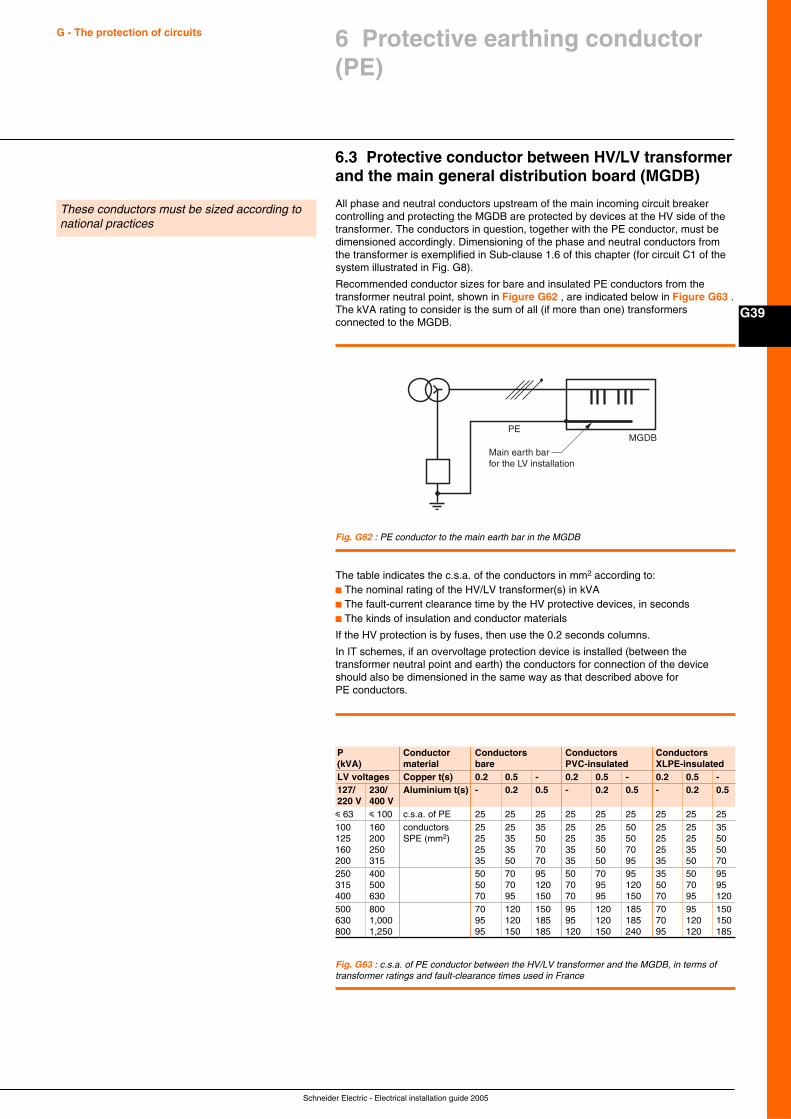
Schneider Electric - Electrical installation guide 2005
G39
G - The protection of circuits 6 Protective earthing conductor(PE)
6.3 Protective conductor between HV/LV transformerand the main general distribution board (MGDB)
All phase and neutral conductors upstream of the main incoming circuit breakercontrolling and protecting the MGDB are protected by devices at the HV side of thetransformer. The conductors in question, together with the PE conductor, must bedimensioned accordingly. Dimensioning of the phase and neutral conductors fromthe transformer is exemplified in Sub-clause 1.6 of this chapter (for circuit C1 of thesystem illustrated in Fig. G8).
Recommended conductor sizes for bare and insulated PE conductors from thetransformer neutral point, shown in Figure G62 , are indicated below in Figure G63 .The kVA rating to consider is the sum of all (if more than one) transformersconnected to the MGDB.
These conductors must be sized according tonational practices
PEMGDB
Main earth barfor the LV installation
Fig. G62 : PE conductor to the main earth bar in the MGDB
Fig. G63 : c.s.a. of PE conductor between the HV/LV transformer and the MGDB, in terms oftransformer ratings and fault-clearance times used in France
P Conductor Conductors Conductors Conductors(kVA) material bare PVC-insulated XLPE-insulatedLV voltages Copper t(s) 0.2 0.5 - 0.2 0.5 - 0.2 0.5 -127/ 230/ Aluminium t(s) - 0.2 0.5 - 0.2 0.5 - 0.2 0.5220 V 400 Vi 63 i 100 c.s.a. of PE 25 25 25 25 25 25 25 25 25100 160 conductors 25 25 35 25 25 50 25 25 35125 200 SPE (mm2) 25 35 50 25 35 50 25 25 50160 250 25 35 70 35 50 70 25 35 50200 315 35 50 70 35 50 95 35 50 70250 400 50 70 95 50 70 95 35 50 95315 500 50 70 120 70 95 120 50 70 95400 630 70 95 150 70 95 150 70 95 120500 800 70 120 150 95 120 185 70 95 150630 1,000 95 120 185 95 120 185 70 120 150800 1,250 95 150 185 120 150 240 95 120 185
The table indicates the c.s.a. of the conductors in mm2 according to:c The nominal rating of the HV/LV transformer(s) in kVAc The fault-current clearance time by the HV protective devices, in secondsc The kinds of insulation and conductor materials
If the HV protection is by fuses, then use the 0.2 seconds columns.
In IT schemes, if an overvoltage protection device is installed (between thetransformer neutral point and earth) the conductors for connection of the deviceshould also be dimensioned in the same way as that described above forPE conductors.
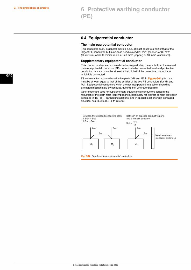
Schneider Electric - Electrical installation guide 2005
G40
G - The protection of circuits 6 Protective earthing conductor(PE)
Fig. G64 : Supplementary equipotential conductors
M1 M2
Between two exposed conductive partsif SPE1 i SPE2
if SLS = SPE1
Between an exposed conductive partsand a metallic structure
M1
Metal structures(conduits, girders…)
2
SPE1 SPE1SPE2
SPE
SLS SLS
SLS =
6.4 Equipotential conductor
The main equipotential conductorThis conductor must, in general, have a c.s.a. at least equal to a half of that of thelargest PE conductor, but in no case need exceed 25 mm2 (copper) or 35 mm2
(aluminium) while its minimum c.s.a. is 6 mm2 (copper) or 10 mm2 (aluminium).
Supplementary equipotential conductorThis conductor allows an exposed conductive part which is remote from the nearestmain equipotential conductor (PE conductor) to be connected to a local protectiveconductor. Its c.s.a. must be at least a half of that of the protective conductor towhich it is connected.
If it connects two exposed conductive parts (M1 and M2 in Figure G64 ) its c.s.a.must be at least equal to that of the smaller of the two PE conductors (for M1 andM2). Equipotential conductors which are not incorporated in a cable, should beprotected mechanically by conduits, ducting, etc. wherever possible.
Other important uses for supplementary equipotential conductors concern thereduction of the earth-fault-loop impedance, particulary for indirect-contact protectionschemes in TN- or IT-earthed installations, and in special locations with increasedelectrical risk (IEC 60364-4-41 refers).
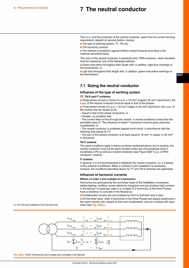
Schneider Electric - Electrical installation guide 2005
G41
G - The protection of circuits 7 The neutral conductor
The c.s.a. and the protection of the neutral conductor, apart from its current-carryingrequirement, depend on several factors, namely:c The type of earthing system, TT, TN, etc.c The harmonic currentsc The method of protection against indirect contact hazards according to themethods described below
The color of the neutral conductor is statutorily blue. PEN conductor, when insulated,shall be marked by one of the following methods :c Green-and-yellow throughout their length with, in addition, light blue markings atthe terminations, orc Ligh blue throughout their length with, in addition, green-and-yellow markings atthe terminations
7.1 Sizing the neutral conductor
Influence of the type of earthing systemTT, TN-S and IT schemesc Single-phase circuits or those of c.s.a. i 16 mm2 (copper) 25 mm2 (aluminium): thec.s.a. of the neutral conductor must be equal to that of the phasesc Three-phase circuits of c.s.a. > 16 mm2 copper or 25 mm2 aluminium: the c.s.a. ofthe neutral may be chosen to be:v Equal to that of the phase conductors, orv Smaller, on condition that:- The current likely to flow through the neutral in normal conditions is less than thepermitted value Iz. The influence of triplen(1) harmonics must be given particularconsideration or- The neutral conductor is protected against short-circuit, in accordance with thefollowing Sub-clause G-7.2- The size of the neutral conductor is at least equal to 16 mm2 in copper or 25 mm2
in aluminium
TN-C schemeThe same conditions apply in theory as those mentioned above, but in practice, theneutral conductor must not be open-circuited under any circumstances since itconstitutes a PE as well as a neutral conductor (see Figure G60 “c.s.a. of PENconductor” column).
IT schemeIn general, it is not recommended to distribute the neutral conductor, i.e. a 3-phase3-wire scheme is preferred. When a 3-phase 4-wire installation is necessary,however, the conditions described above for TT and TN-S schemes are applicable.
Influence of harmonic currentsEffects of order 3 and multiple of 3 harmonicsHarmonics are generated by the non-linear loads of the installation (computers,ballast lighting, rectifiers, power electronic choppers) and can produce high currentsin the Neutral. In particular order 3 or multiple of 3 harmonics of the three Phaseshave a tendency to cumulate in the Neutral as:c Fundamental currents are out-of-phase by 2π/3 so that their sum is zeroc On the other hand, order 3 harmonics of the three Phases are always positioned inthe same manner with respect to their own fundamental, and are in phase with eachother (see Fig. G65a ).(1) The 3rd and multiples of the 3rd harmonic
Fig. G65a : Order 3 harmonics are in phase and cumulate in the Neutral
+I1 H1 I1 H3
I2 H1 + I2 H3
I3 H1
Ik H1IN =
1
3
+
+
I3 H3
Σ Ik H3
0 + IH3
1
3
3
Σ
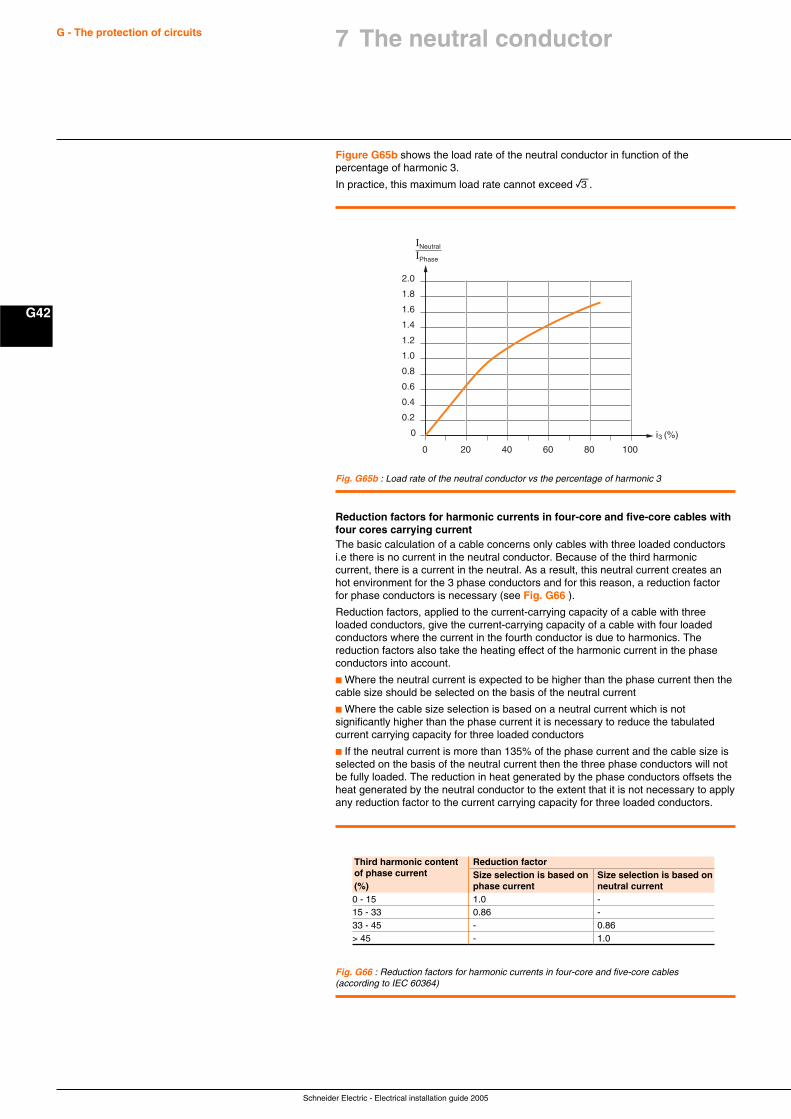
Schneider Electric - Electrical installation guide 2005
G42
G - The protection of circuits
Figure G65b shows the load rate of the neutral conductor in function of thepercentage of harmonic 3.
In practice, this maximum load rate cannot exceed e.
Reduction factors for harmonic currents in four-core and five-core cables withfour cores carrying currentThe basic calculation of a cable concerns only cables with three loaded conductorsi.e there is no current in the neutral conductor. Because of the third harmoniccurrent, there is a current in the neutral. As a result, this neutral current creates anhot environment for the 3 phase conductors and for this reason, a reduction factorfor phase conductors is necessary (see Fig. G66 ).
Reduction factors, applied to the current-carrying capacity of a cable with threeloaded conductors, give the current-carrying capacity of a cable with four loadedconductors where the current in the fourth conductor is due to harmonics. Thereduction factors also take the heating effect of the harmonic current in the phaseconductors into account.
c Where the neutral current is expected to be higher than the phase current then thecable size should be selected on the basis of the neutral current
c Where the cable size selection is based on a neutral current which is notsignificantly higher than the phase current it is necessary to reduce the tabulatedcurrent carrying capacity for three loaded conductors
c If the neutral current is more than 135% of the phase current and the cable size isselected on the basis of the neutral current then the three phase conductors will notbe fully loaded. The reduction in heat generated by the phase conductors offsets theheat generated by the neutral conductor to the extent that it is not necessary to applyany reduction factor to the current carrying capacity for three loaded conductors.
Fig. G65b : Load rate of the neutral conductor vs the percentage of harmonic 3
0 20 40 60 80 100
INeutral
IPhase
i3 (%)0
0.2
0.4
0.6
0.8
1.0
1.2
1.4
1.6
1.8
2.0
Fig. G66 : Reduction factors for harmonic currents in four-core and five-core cables(according to IEC 60364)
Third harmonic content Reduction factorof phase current Size selection is based on Size selection is based on(%) phase current neutral current0 - 15 1.0 -15 - 33 0.86 -33 - 45 - 0.86> 45 - 1.0
7 The neutral conductor
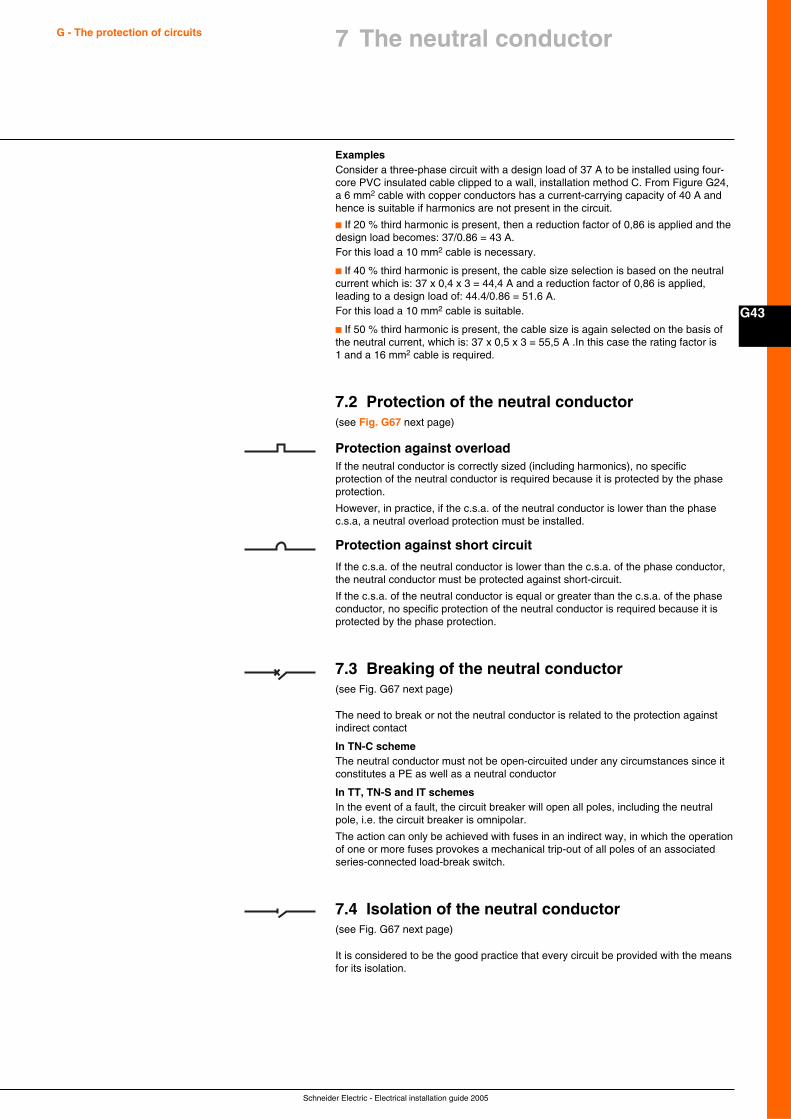
Schneider Electric - Electrical installation guide 2005
G43
G - The protection of circuits 7 The neutral conductor
ExamplesConsider a three-phase circuit with a design load of 37 A to be installed using four-core PVC insulated cable clipped to a wall, installation method C. From Figure G24,a 6 mm2 cable with copper conductors has a current-carrying capacity of 40 A andhence is suitable if harmonics are not present in the circuit.
c If 20 % third harmonic is present, then a reduction factor of 0,86 is applied and thedesign load becomes: 37/0.86 = 43 A.For this load a 10 mm2 cable is necessary.
c If 40 % third harmonic is present, the cable size selection is based on the neutralcurrent which is: 37 x 0,4 x 3 = 44,4 A and a reduction factor of 0,86 is applied,leading to a design load of: 44.4/0.86 = 51.6 A.For this load a 10 mm2 cable is suitable.
c If 50 % third harmonic is present, the cable size is again selected on the basis ofthe neutral current, which is: 37 x 0,5 x 3 = 55,5 A .In this case the rating factor is1 and a 16 mm2 cable is required.
7.2 Protection of the neutral conductor(see Fig. G67 next page)
Protection against overloadIf the neutral conductor is correctly sized (including harmonics), no specificprotection of the neutral conductor is required because it is protected by the phaseprotection.
However, in practice, if the c.s.a. of the neutral conductor is lower than the phasec.s.a, a neutral overload protection must be installed.
Protection against short circuit
If the c.s.a. of the neutral conductor is lower than the c.s.a. of the phase conductor,the neutral conductor must be protected against short-circuit.
If the c.s.a. of the neutral conductor is equal or greater than the c.s.a. of the phaseconductor, no specific protection of the neutral conductor is required because it isprotected by the phase protection.
7.3 Breaking of the neutral conductor(see Fig. G67 next page)
The need to break or not the neutral conductor is related to the protection againstindirect contact
In TN-C schemeThe neutral conductor must not be open-circuited under any circumstances since itconstitutes a PE as well as a neutral conductor
In TT, TN-S and IT schemesIn the event of a fault, the circuit breaker will open all poles, including the neutralpole, i.e. the circuit breaker is omnipolar.
The action can only be achieved with fuses in an indirect way, in which the operationof one or more fuses provokes a mechanical trip-out of all poles of an associatedseries-connected load-break switch.
7.4 Isolation of the neutral conductor(see Fig. G67 next page)
It is considered to be the good practice that every circuit be provided with the meansfor its isolation.
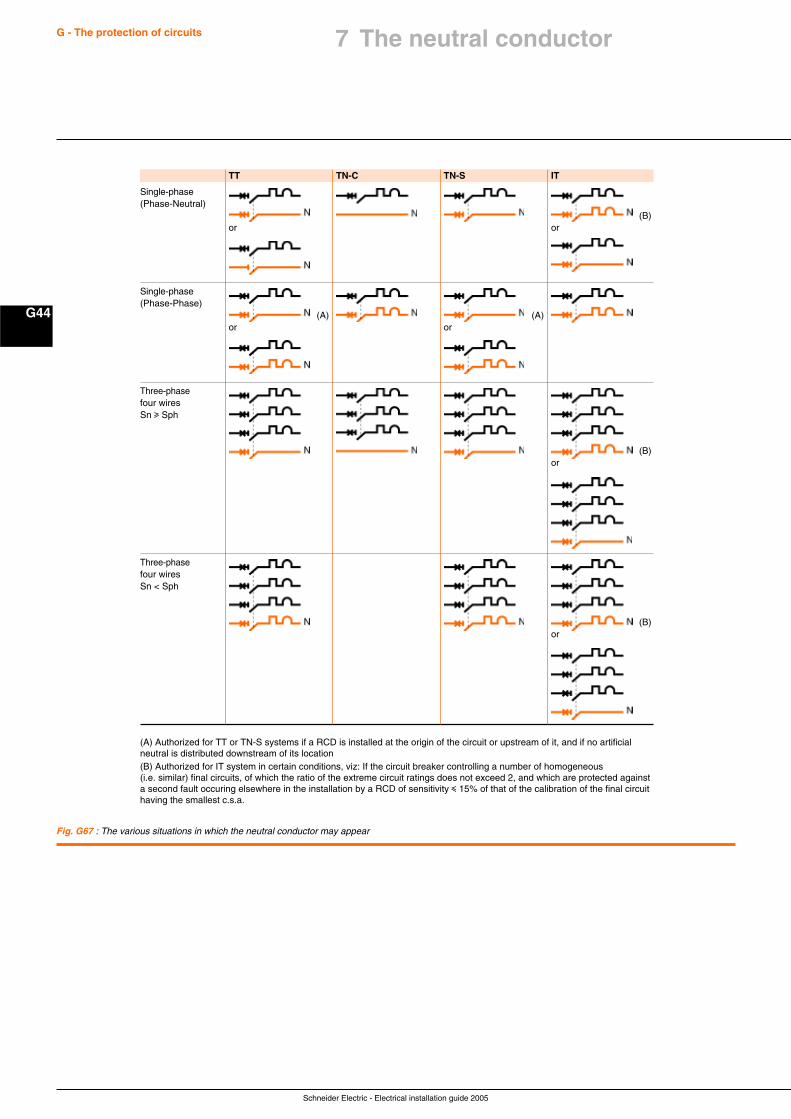
Schneider Electric - Electrical installation guide 2005
G44
G - The protection of circuits
Fig. G67 : The various situations in which the neutral conductor may appear
TT TN-C TN-S IT
Single-phase(Phase-Neutral)
(B)or or
Single-phase(Phase-Phase)
(A) (A)or or
Three-phasefour wiresSn u Sph
(B)or
Three-phasefour wiresSn < Sph
(B)or
(A) Authorized for TT or TN-S systems if a RCD is installed at the origin of the circuit or upstream of it, and if no artificialneutral is distributed downstream of its location(B) Authorized for IT system in certain conditions, viz: If the circuit breaker controlling a number of homogeneous(i.e. similar) final circuits, of which the ratio of the extreme circuit ratings does not exceed 2, and which are protected againsta second fault occuring elsewhere in the installation by a RCD of sensitivity i 15% of that of the calibration of the final circuithaving the smallest c.s.a.
7 The neutral conductor
Schneider Electric - Electrical installation guide 2005
H1
Chapter HThe switchgear
Contents
The basic functions of LV switchgear H2
1.1 Electrical protection H2
1.2 Isolation H3
1.3 Switchgear control H4
The switchgear H5
2.1 Elementary switching devices H5
2.2 Combined switchgear elements H9
Choice of switchgear H10
3.1 Tabulated functional capabilities H10
3.2 Switchgear selection H10
Circuit breaker H11
4.1 Standards and description H11
4.2 Fundamental characteristics of a circuit breaker H13
4.3 Other characteristics of a circuit breaker H15
4.4 Selection of a circuit breaker H18
4.5 Coordination between circuit breakers H22
4.6 Discrimination HV/LV in a consumer’s substation H28
1
2
3
4
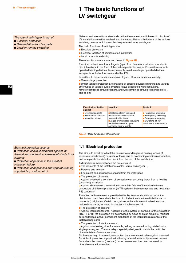
Schneider Electric - Electrical installation guide 2005
H2
H - The switchgear 1 The basic functions ofLV switchgear
The role of switchgear is that of:c Electrical protectionc Safe isolation from live partsc Local or remote switching
National and international standards define the manner in which electric circuits ofLV installations must be realized, and the capabilities and limitations of the variousswitching devices which are collectively referred to as switchgear.
The main functions of switchgear are:c Electrical protectionc Electrical isolation of sections of an installationc Local or remote switching
These functions are summarized below in Figure H1 .
Electrical protection at low voltage is (apart from fuses) normally incorporated incircuit breakers, in the form of thermal-magnetic devices and/or residual-current-operated tripping devices (less-commonly, residualvoltage- operated devices -acceptable to, but not recommended by IEC).
In addition to those functions shown in Figure H1, other functions, namely:c Over-voltage protectionc Under-voltage protection are provided by specific devices (lightning and variousother types of voltage-surge arrester; relays associated with: contactors,remotelycontrolled circuit breakers, and with combined circuit breaker/isolators…and so on)
Fig. H1 : Basic functions of LV switchgear
1.1 Electrical protection
The aim is to avoid or to limit the destructive or dangerous consequences ofexcessive (short-circuit) currents, or those due to overloading and insulation failure,and to separate the defective circuit from the rest of the installation.
A distinction is made between the protection of:c The elements of the installation (cables, wires, switchgear…)c Persons and animalsc Equipment and appliances supplied from the installationc The protection of circuits:v Against overload; a condition of excessive current being drawn from a healthy(unfaulted) installationv Against short-circuit currents due to complete failure of insulation betweenconductors of different phases or (in TN systems) between a phase and neutral (orPE) conductor
Protection in these cases is provided either by fuses or circuit breaker, at thedistribution board from which the final circuit (i.e. the circuit to which the load isconnected) originates. Certain derogations to this rule are authorized in somenational standards, as noted in chapter H1 sub-clause 1.4.c The protection of persons:v Against insulation failures. According to the system of earthing for the installation(TN, TT or IT) the protection will be provided by fuses or circuit breakers, residualcurrent devices, and/or permanent monitoring of the insulation resistance of theinstallation to earthc The protection of electric motors:v Against overheating, due, for example, to long term overloading; stalled rotor;single-phasing, etc. Thermal relays, specially designed to match the particularcharacteristics of motors are used.Such relays may, if required, also protect the motor-circuit cable against overload.Shortcircuit protection is provided either by type aM fuses or by a circuit breakerfrom which the thermal (overload) protective element has been removed, orotherwise made inoperative
Electrical protection assures:c Protection of circuit elements against thethermal and mechanical stresses of short-circuitcurrentsc Protection of persons in the event ofinsulation failurec Protection of appliances and apparatus beingsupplied (e.g. motors, etc.)
Electrical protection Isolation Controlagainstc Overload currents c Isolation clearly indicated c Functional switchingc Short-circuit currents by an authorized fail-proof c Emergency switchingc Insulation failure mechanical indicator c Emergency stopping
c A gap or interposed insulating c Switching off forbarrier between the open mechanical maintenancecontacts, clearly visible
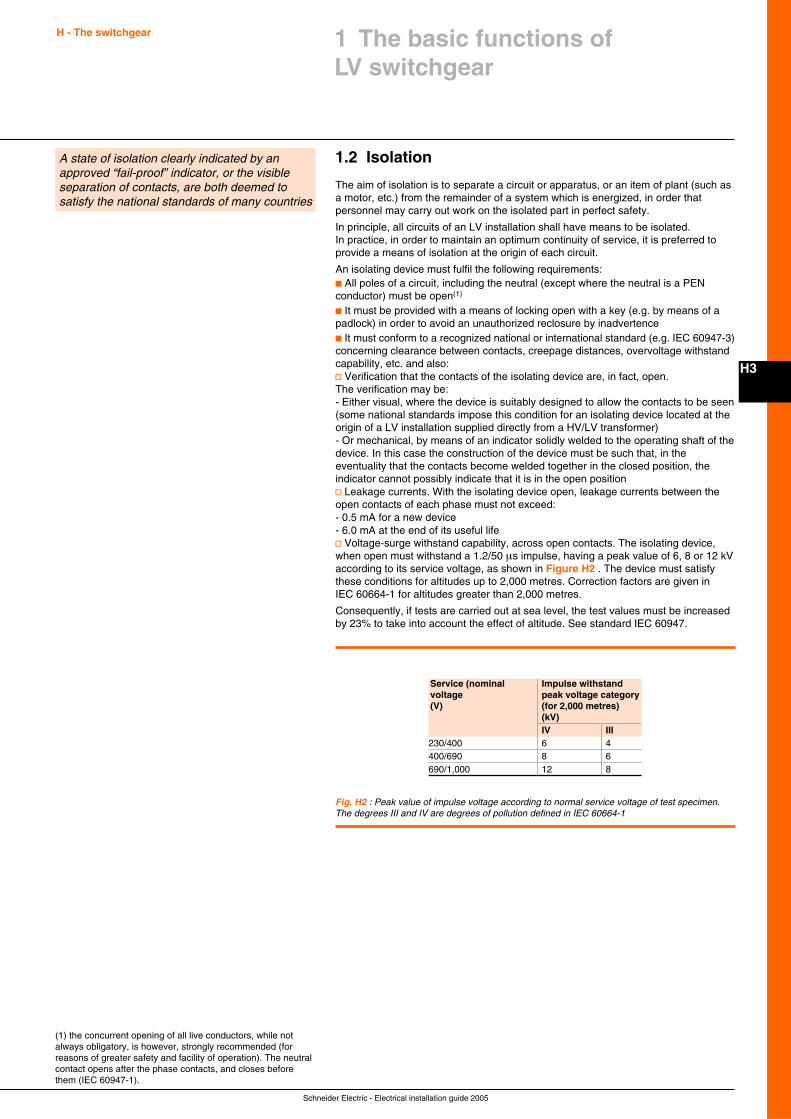
Schneider Electric - Electrical installation guide 2005
H3
H - The switchgear
1.2 Isolation
The aim of isolation is to separate a circuit or apparatus, or an item of plant (such asa motor, etc.) from the remainder of a system which is energized, in order thatpersonnel may carry out work on the isolated part in perfect safety.
In principle, all circuits of an LV installation shall have means to be isolated.In practice, in order to maintain an optimum continuity of service, it is preferred toprovide a means of isolation at the origin of each circuit.
An isolating device must fulfil the following requirements:c All poles of a circuit, including the neutral (except where the neutral is a PENconductor) must be open(1)
c It must be provided with a means of locking open with a key (e.g. by means of apadlock) in order to avoid an unauthorized reclosure by inadvertencec It must conform to a recognized national or international standard (e.g. IEC 60947-3)concerning clearance between contacts, creepage distances, overvoltage withstandcapability, etc. and also:v Verification that the contacts of the isolating device are, in fact, open.The verification may be:- Either visual, where the device is suitably designed to allow the contacts to be seen(some national standards impose this condition for an isolating device located at theorigin of a LV installation supplied directly from a HV/LV transformer)- Or mechanical, by means of an indicator solidly welded to the operating shaft of thedevice. In this case the construction of the device must be such that, in theeventuality that the contacts become welded together in the closed position, theindicator cannot possibly indicate that it is in the open positionv Leakage currents. With the isolating device open, leakage currents between theopen contacts of each phase must not exceed:- 0.5 mA for a new device- 6.0 mA at the end of its useful lifev Voltage-surge withstand capability, across open contacts. The isolating device,when open must withstand a 1.2/50 µs impulse, having a peak value of 6, 8 or 12 kVaccording to its service voltage, as shown in Figure H2 . The device must satisfythese conditions for altitudes up to 2,000 metres. Correction factors are given inIEC 60664-1 for altitudes greater than 2,000 metres.
Consequently, if tests are carried out at sea level, the test values must be increasedby 23% to take into account the effect of altitude. See standard IEC 60947.
1 The basic functions ofLV switchgear
A state of isolation clearly indicated by anapproved “fail-proof” indicator, or the visibleseparation of contacts, are both deemed tosatisfy the national standards of many countries
(1) the concurrent opening of all live conductors, while notalways obligatory, is however, strongly recommended (forreasons of greater safety and facility of operation). The neutralcontact opens after the phase contacts, and closes beforethem (IEC 60947-1).
Service (nominal Impulse withstandvoltage peak voltage category(V) (for 2,000 metres)
(kV)IV III
230/400 6 4400/690 8 6690/1,000 12 8
Fig. H2 : Peak value of impulse voltage according to normal service voltage of test specimen.The degrees III and IV are degrees of pollution defined in IEC 60664-1
Schneider Electric - Electrical installation guide 2005
H - The switchgear
H4
1.3 Switchgear control
In broad terms “control” signifies any facility for safely modifying a load-carryingpower system at all levels of an installation. The operation of switchgear is animportant part of power-system control.
Functional controlThis control relates to all switching operations in normal service conditions forenergizing or de-energizing a part of a system or installation, or an individual pieceof equipment, item of plant, etc.
Switchgear intended for such duty must be installed at least:c At the origin of any installationc At the final load circuit or circuits (one switch may control several loads)
Marking (of the circuits being controlled) must be clear and unambiguous.
In order to provide the maximum flexibility and continuity of operation, particularlywhere the switching device also constitutes the protection (e.g. a circuit breaker orswitch-fuse) it is preferable to include a switch at each level of distribution, i.e. oneach outgoing way of all distribution and subdistribution boards.
The manœuvre may be:c Either manual (by means of an operating lever on the switch) orc Electric, by push-button on the switch or at a remote location (load-shedding andreconnection, for example)
These switches operate instantaneously (i.e. with no deliberate delay), and thosethat provide protection are invariably omni-polar(1).
The main circuit breaker for the entire installation, as well as any circuit breakersused for change-over (from one source to another) must be omni-polar units.
Emergency switching - emergency stopAn emergency switching is intended to de-energize a live circuit which is, or couldbecome, dangerous (electric shock or fire).
An emergency stop is intended to arrest a movement which has become dangerous.In the two cases:c The emergency control device or its means of operation (local or at remotelocation(s)) such as a large red mushroom-headed emergency-stop pushbutton mustbe recognizable and readily accessible, in proximity to any position at which dangercould arise or be seenc A single action must result in a complete switching-off of all live conductors (2) (3)
c A “break glass” emergency switching initiation device is authorized, but inunmanned installations the re-energizing of the circuit can only be achieved bymeans of a key held by an authorized person
It should be noted that in certain cases, an emergency system of braking, mayrequire that the auxiliary supply to the braking-system circuits be maintained untilfinal stoppage of the machinery.
Switching-off for mechanical maintenance workThis operation assures the stopping of a machine and its impossibility to beinadvertently restarted while mechanical maintenance work is being carried out onthe driven machinery. The shutdown is generally carried out at the functionalswitching device, with the use of a suitable safety lock and warning notice at theswitch mechanism.
(1) One break in each phase and (where appropriate) onebreak in the neutral.(2) Taking into account stalled motors.(3) In a TN schema the PEN conductor must never beopened, since it functions as a protective earthing wire as wellas the system neutral conductor.
1 The basic functions ofLV switchgear
Switchgear-control functions allow systemoperating personnel to modify a loaded systemat any moment, according to requirements,and include:c Functional control (routine switching, etc.)c Emergency switchingc Maintenance operations on the power system
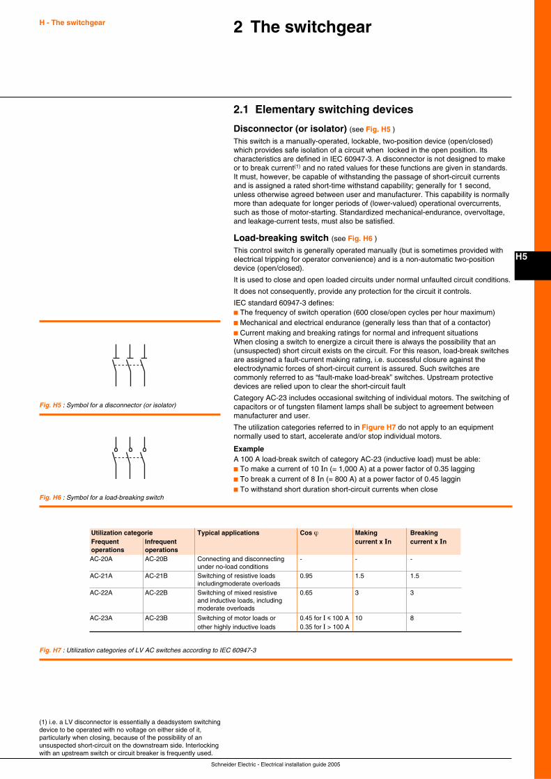
Schneider Electric - Electrical installation guide 2005
H5
2 The switchgearH - The switchgear
2.1 Elementary switching devices
Disconnector (or isolator) (see Fig. H5 )
This switch is a manually-operated, lockable, two-position device (open/closed)which provides safe isolation of a circuit when locked in the open position. Itscharacteristics are defined in IEC 60947-3. A disconnector is not designed to makeor to break current(1) and no rated values for these functions are given in standards.It must, however, be capable of withstanding the passage of short-circuit currentsand is assigned a rated short-time withstand capability; generally for 1 second,unless otherwise agreed between user and manufacturer. This capability is normallymore than adequate for longer periods of (lower-valued) operational overcurrents,such as those of motor-starting. Standardized mechanical-endurance, overvoltage,and leakage-current tests, must also be satisfied.
Load-breaking switch (see Fig. H6 )
This control switch is generally operated manually (but is sometimes provided withelectrical tripping for operator convenience) and is a non-automatic two-positiondevice (open/closed).
It is used to close and open loaded circuits under normal unfaulted circuit conditions.
It does not consequently, provide any protection for the circuit it controls.
IEC standard 60947-3 defines:c The frequency of switch operation (600 close/open cycles per hour maximum)c Mechanical and electrical endurance (generally less than that of a contactor)c Current making and breaking ratings for normal and infrequent situationsWhen closing a switch to energize a circuit there is always the possibility that an(unsuspected) short circuit exists on the circuit. For this reason, load-break switchesare assigned a fault-current making rating, i.e. successful closure against theelectrodynamic forces of short-circuit current is assured. Such switches arecommonly referred to as “fault-make load-break” switches. Upstream protectivedevices are relied upon to clear the short-circuit fault
Category AC-23 includes occasional switching of individual motors. The switching ofcapacitors or of tungsten filament lamps shall be subject to agreement betweenmanufacturer and user.
The utilization categories referred to in Figure H7 do not apply to an equipmentnormally used to start, accelerate and/or stop individual motors.
ExampleA 100 A load-break switch of category AC-23 (inductive load) must be able:c To make a current of 10 In (= 1,000 A) at a power factor of 0.35 laggingc To break a current of 8 In (= 800 A) at a power factor of 0.45 lagginc To withstand short duration short-circuit currents when close
(1) i.e. a LV disconnector is essentially a deadsystem switchingdevice to be operated with no voltage on either side of it,particularly when closing, because of the possibility of anunsuspected short-circuit on the downstream side. Interlockingwith an upstream switch or circuit breaker is frequently used.
Fig. H7 : Utilization categories of LV AC switches according to IEC 60947-3
Fig. H5 : Symbol for a disconnector (or isolator)
Fig. H6 : Symbol for a load-breaking switch
Utilization categorie Typical applications Cos ϕ Making BreakingFrequent Infrequent current x In current x Inoperations operationsAC-20A AC-20B Connecting and disconnecting - - -
under no-load conditionsAC-21A AC-21B Switching of resistive loads 0.95 1.5 1.5
includingmoderate overloadsAC-22A AC-22B Switching of mixed resistive 0.65 3 3
and inductive loads, includingmoderate overloads
AC-23A AC-23B Switching of motor loads or 0.45 for I i 100 A 10 8other highly inductive loads 0.35 for I > 100 A
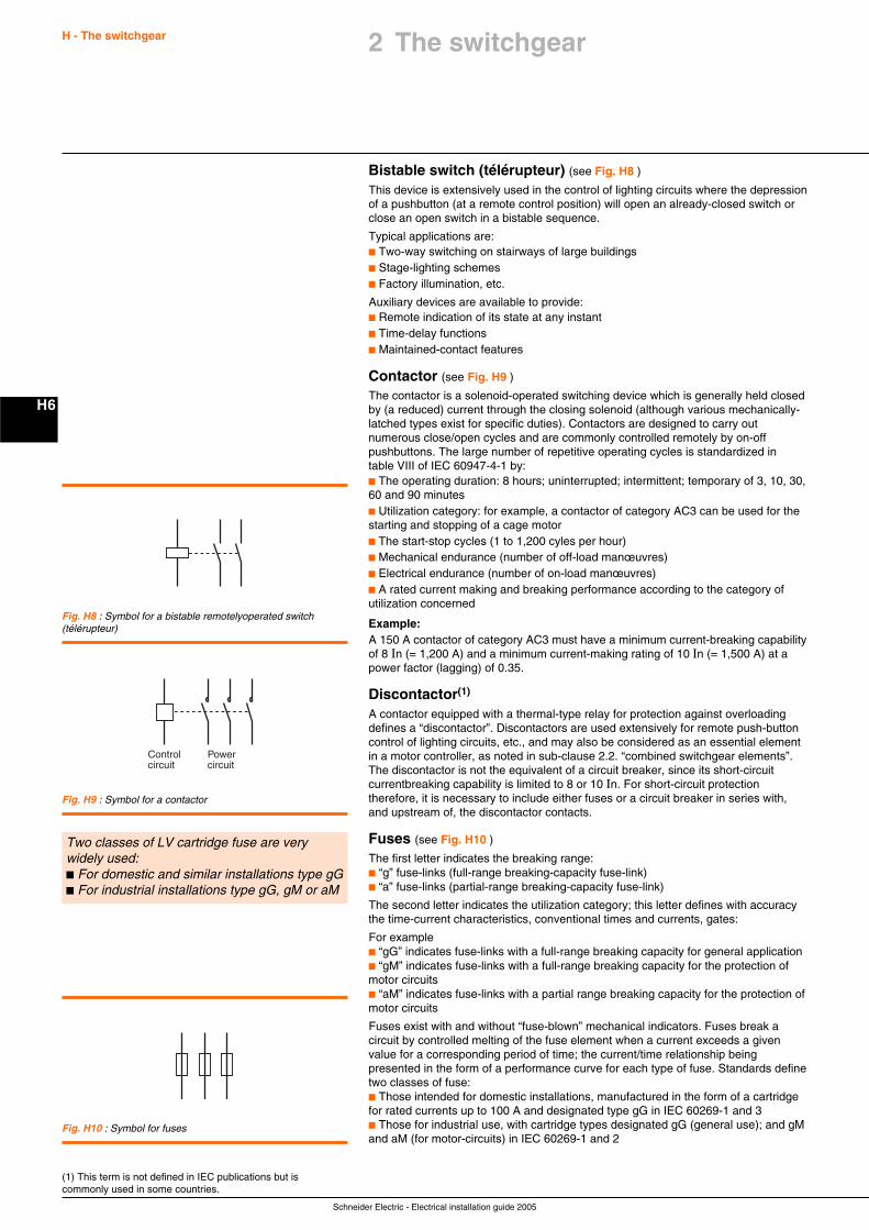
Schneider Electric - Electrical installation guide 2005
H - The switchgear
H6
Bistable switch (télérupteur) (see Fig. H8 )
This device is extensively used in the control of lighting circuits where the depressionof a pushbutton (at a remote control position) will open an already-closed switch orclose an open switch in a bistable sequence.
Typical applications are:c Two-way switching on stairways of large buildingsc Stage-lighting schemesc Factory illumination, etc.
Auxiliary devices are available to provide:c Remote indication of its state at any instantc Time-delay functionsc Maintained-contact features
Contactor (see Fig. H9 )
The contactor is a solenoid-operated switching device which is generally held closedby (a reduced) current through the closing solenoid (although various mechanically-latched types exist for specific duties). Contactors are designed to carry outnumerous close/open cycles and are commonly controlled remotely by on-offpushbuttons. The large number of repetitive operating cycles is standardized intable VIII of IEC 60947-4-1 by:c The operating duration: 8 hours; uninterrupted; intermittent; temporary of 3, 10, 30,60 and 90 minutesc Utilization category: for example, a contactor of category AC3 can be used for thestarting and stopping of a cage motorc The start-stop cycles (1 to 1,200 cyles per hour)c Mechanical endurance (number of off-load manœuvres)c Electrical endurance (number of on-load manœuvres)c A rated current making and breaking performance according to the category ofutilization concerned
Example:A 150 A contactor of category AC3 must have a minimum current-breaking capabilityof 8 In (= 1,200 A) and a minimum current-making rating of 10 In (= 1,500 A) at apower factor (lagging) of 0.35.
Discontactor(1)
A contactor equipped with a thermal-type relay for protection against overloadingdefines a “discontactor”. Discontactors are used extensively for remote push-buttoncontrol of lighting circuits, etc., and may also be considered as an essential elementin a motor controller, as noted in sub-clause 2.2. “combined switchgear elements”.The discontactor is not the equivalent of a circuit breaker, since its short-circuitcurrentbreaking capability is limited to 8 or 10 In. For short-circuit protectiontherefore, it is necessary to include either fuses or a circuit breaker in series with,and upstream of, the discontactor contacts.
Fuses (see Fig. H10 )
The first letter indicates the breaking range:c “g” fuse-links (full-range breaking-capacity fuse-link)c “a” fuse-links (partial-range breaking-capacity fuse-link)
The second letter indicates the utilization category; this letter defines with accuracythe time-current characteristics, conventional times and currents, gates:
For examplec “gG” indicates fuse-links with a full-range breaking capacity for general applicationc “gM” indicates fuse-links with a full-range breaking capacity for the protection ofmotor circuitsc “aM” indicates fuse-links with a partial range breaking capacity for the protection ofmotor circuits
Fuses exist with and without “fuse-blown” mechanical indicators. Fuses break acircuit by controlled melting of the fuse element when a current exceeds a givenvalue for a corresponding period of time; the current/time relationship beingpresented in the form of a performance curve for each type of fuse. Standards definetwo classes of fuse:c Those intended for domestic installations, manufactured in the form of a cartridgefor rated currents up to 100 A and designated type gG in IEC 60269-1 and 3c Those for industrial use, with cartridge types designated gG (general use); and gMand aM (for motor-circuits) in IEC 60269-1 and 2
Fig. H8 : Symbol for a bistable remotelyoperated switch(télérupteur)
Control circuit
Power circuit
Fig. H9 : Symbol for a contactor
(1) This term is not defined in IEC publications but iscommonly used in some countries.
Two classes of LV cartridge fuse are verywidely used:c For domestic and similar installations type gGc For industrial installations type gG, gM or aM
Fig. H10 : Symbol for fuses
2 The switchgear
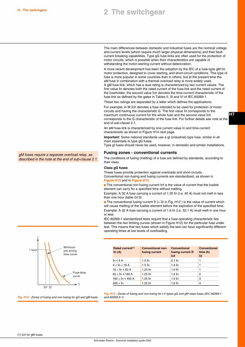
Schneider Electric - Electrical installation guide 2005
H - The switchgear
H7
The main differences between domestic and industrial fuses are the nominal voltageand current levels (which require much larger physical dimensions) and their fault-current breaking capabilities. Type gG fuse-links are often used for the protection ofmotor circuits, which is possible when their characteristics are capable ofwithstanding the motor-starting current without deterioration.
A more recent development has been the adoption by the IEC of a fuse-type gM formotor protection, designed to cover starting, and short-circuit conditions. This type offuse is more popular in some countries than in others, but at the present time theaM fuse in combination with a thermal overload relay is more-widely used.A gM fuse-link, which has a dual rating is characterized by two current values. Thefirst value In denotes both the rated current of the fuse-link and the rated current ofthe fuseholder; the second value Ich denotes the time-current characteristic of thefuse-link as defined by the gates in Tables II, III and VI of IEC 60269-1.
These two ratings are separated by a letter which defines the applications.
For example: In M Ich denotes a fuse intended to be used for protection of motorcircuits and having the characteristic G. The first value In corresponds to themaximum continuous current for the whole fuse and the second value Ichcorresponds to the G characteristic of the fuse link. For further details see note at theend of sub-clause 2.1.
An aM fuse-link is characterized by one current value In and time-currentcharacteristic as shown in Figure H14 next page.
Important: Some national standards use a gI (industrial) type fuse, similar in allmain essentails to type gG fuses.Type gI fuses should never be used, however, in domestic and similar installations.
Fusing zones - conventional currentsThe conditions of fusing (melting) of a fuse are defined by standards, according totheir class.
Class gG fusesThese fuses provide protection against overloads and short-circuits.Conventional non-fusing and fusing currents are standardized, as shown inFigure H12 and in Figure H13 .c The conventional non-fusing current Inf is the value of current that the fusibleelement can carry for a specified time without melting.Example: A 32 A fuse carrying a current of 1.25 In (i.e. 40 A) must not melt in lessthan one hour (table G13)c The conventional fusing current If (= I2 in Fig. H12 ) is the value of current whichwill cause melting of the fusible element before the expiration of the specified time.Example: A 32 A fuse carrying a current of 1.6 In (i.e. 52.1 A) must melt in one houror lessIEC 60269-1 standardized tests require that a fuse-operating characteristic liesbetween the two limiting curves (shown in Figure H12) for the particular fuse undertest. This means that two fuses which satisfy the test can have significantly differentoperating times at low levels of overloading.
gM fuses require a separate overload relay, asdescribed in the note at the end of sub-clause 2.1.
1 hour
t
Minimum pre-arcing time curve
Fuse-blowcurve
IInf I2
2 The switchgear
Fig. H12 : Zones of fusing and non-fusing for gG and gM fuses
(1) Ich for gM fuses
Fig. H13 : Zones of fusing and non-fusing for LV types gG and gM class fuses (IEC 60269-1and 60269-2-1)
Rated current(1) Conventional non- Conventional ConventionalIn (A) fusing current fusing current If time (h)
Inf I2In i 4 A 1.5 In 2.1 In 1
4 < In < 16 A 1.5 In 1.9 In 1
16 < In i 63 A 1.25 In 1.6 In 1
63 < In i 160 A 1.25 In 1.6 In 2
160 < In i 400 A 1.25 In 1.6 In 3
400 < In 1.25 In 1.6 In 4
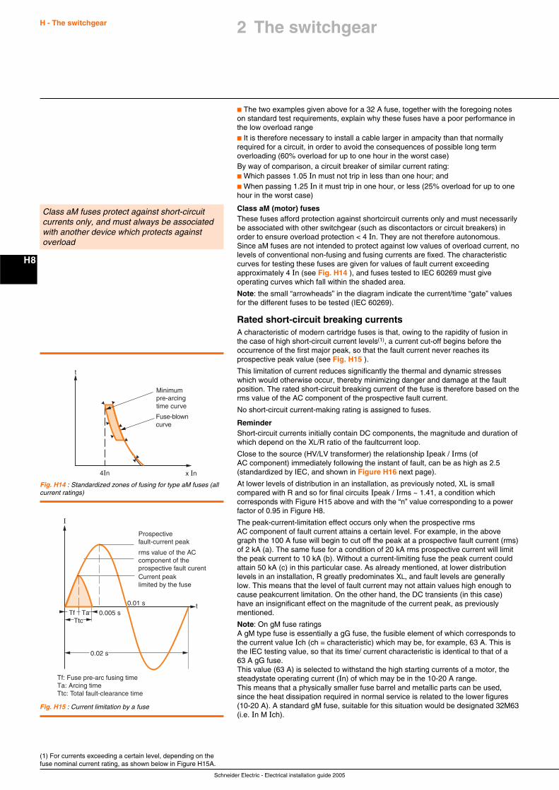
Schneider Electric - Electrical installation guide 2005
H - The switchgear
H8
c The two examples given above for a 32 A fuse, together with the foregoing noteson standard test requirements, explain why these fuses have a poor performance inthe low overload rangec It is therefore necessary to install a cable larger in ampacity than that normallyrequired for a circuit, in order to avoid the consequences of possible long termoverloading (60% overload for up to one hour in the worst case)By way of comparison, a circuit breaker of similar current rating:c Which passes 1.05 In must not trip in less than one hour; andc When passing 1.25 In it must trip in one hour, or less (25% overload for up to onehour in the worst case)
Class aM (motor) fusesThese fuses afford protection against shortcircuit currents only and must necessarilybe associated with other switchgear (such as discontactors or circuit breakers) inorder to ensure overload protection < 4 In. They are not therefore autonomous.Since aM fuses are not intended to protect against low values of overload current, nolevels of conventional non-fusing and fusing currents are fixed. The characteristiccurves for testing these fuses are given for values of fault current exceedingapproximately 4 In (see Fig. H14 ), and fuses tested to IEC 60269 must giveoperating curves which fall within the shaded area.
Note: the small “arrowheads” in the diagram indicate the current/time “gate” valuesfor the different fuses to be tested (IEC 60269).
Rated short-circuit breaking currentsA characteristic of modern cartridge fuses is that, owing to the rapidity of fusion inthe case of high short-circuit current levels(1), a current cut-off begins before theoccurrence of the first major peak, so that the fault current never reaches itsprospective peak value (see Fig. H15 ).
This limitation of current reduces significantly the thermal and dynamic stresseswhich would otherwise occur, thereby minimizing danger and damage at the faultposition. The rated short-circuit breaking current of the fuse is therefore based on therms value of the AC component of the prospective fault current.
No short-circuit current-making rating is assigned to fuses.
ReminderShort-circuit currents initially contain DC components, the magnitude and duration ofwhich depend on the XL/R ratio of the faultcurrent loop.
Close to the source (HV/LV transformer) the relationship Ipeak / Irms (ofAC component) immediately following the instant of fault, can be as high as 2.5(standardized by IEC, and shown in Figure H16 next page).
At lower levels of distribution in an installation, as previously noted, XL is smallcompared with R and so for final circuits Ipeak / Irms ~ 1.41, a condition whichcorresponds with Figure H15 above and with the “n” value corresponding to a powerfactor of 0.95 in Figure H8.
The peak-current-limitation effect occurs only when the prospective rmsAC component of fault current attains a certain level. For example, in the abovegraph the 100 A fuse will begin to cut off the peak at a prospective fault current (rms)of 2 kA (a). The same fuse for a condition of 20 kA rms prospective current will limitthe peak current to 10 kA (b). Without a current-limiting fuse the peak current couldattain 50 kA (c) in this particular case. As already mentioned, at lower distributionlevels in an installation, R greatly predominates XL, and fault levels are generallylow. This means that the level of fault current may not attain values high enough tocause peakcurrent limitation. On the other hand, the DC transients (in this case)have an insignificant effect on the magnitude of the current peak, as previouslymentioned.
Note: On gM fuse ratingsA gM type fuse is essentially a gG fuse, the fusible element of which corresponds tothe current value Ich (ch = characteristic) which may be, for example, 63 A. This isthe IEC testing value, so that its time/ current characteristic is identical to that of a63 A gG fuse.This value (63 A) is selected to withstand the high starting currents of a motor, thesteadystate operating current (In) of which may be in the 10-20 A range.This means that a physically smaller fuse barrel and metallic parts can be used,since the heat dissipation required in normal service is related to the lower figures(10-20 A). A standard gM fuse, suitable for this situation would be designated 32M63(i.e. In M Ich).
Class aM fuses protect against short-circuitcurrents only, and must always be associatedwith another device which protects againstoverload
(1) For currents exceeding a certain level, depending on thefuse nominal current rating, as shown below in Figure H15A.
x In
t
4In
Fuse-blown curve
Minimum pre-arcing time curve
Fig. H14 : Standardized zones of fusing for type aM fuses (allcurrent ratings)
I
0.005 s
0.02 s
0.01 s t
Prospective fault-current peak
rms value of the AC component of the prospective fault curentCurrent peak limited by the fuse
Tf TaTtc
Tf: Fuse pre-arc fusing timeTa: Arcing timeTtc: Total fault-clearance time
Fig. H15 : Current limitation by a fuse
2 The switchgear
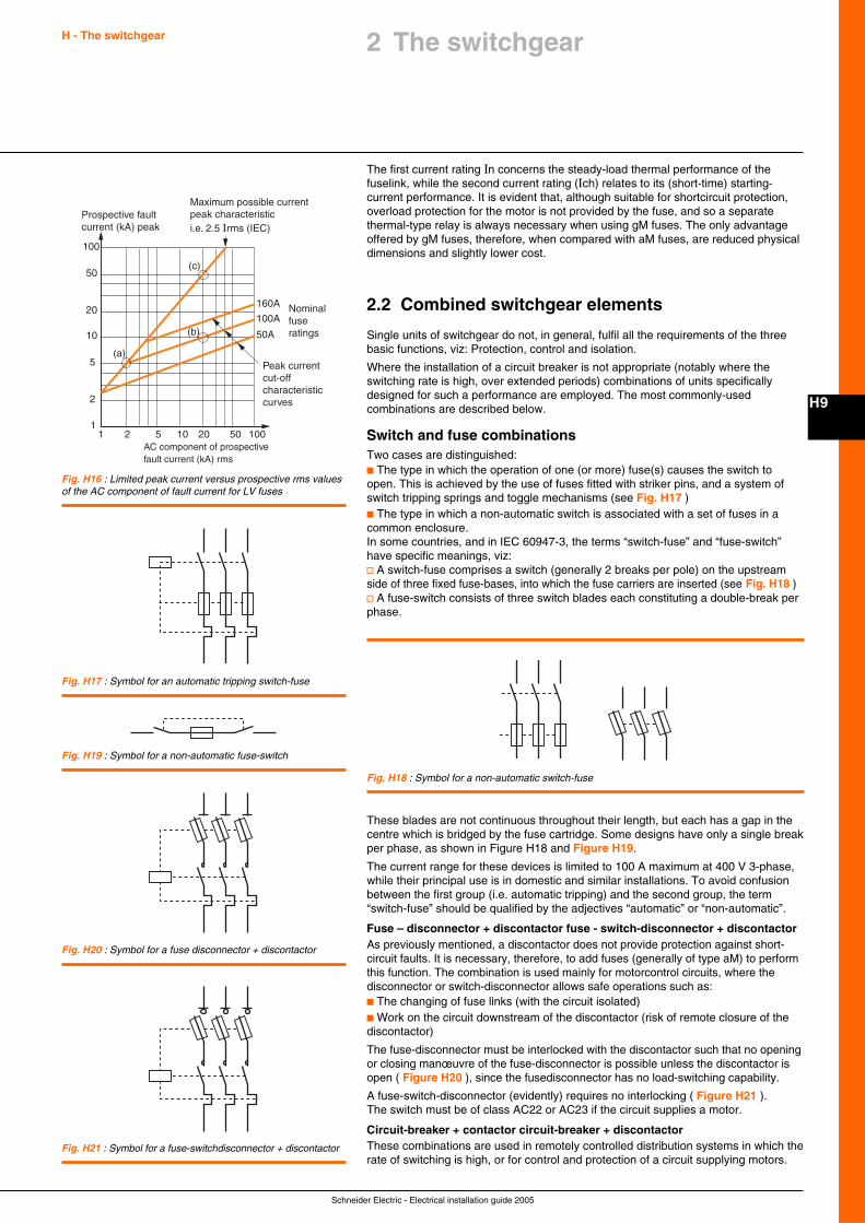
Schneider Electric - Electrical installation guide 2005
H - The switchgear
H9
The first current rating In concerns the steady-load thermal performance of thefuselink, while the second current rating (Ich) relates to its (short-time) starting-current performance. It is evident that, although suitable for shortcircuit protection,overload protection for the motor is not provided by the fuse, and so a separatethermal-type relay is always necessary when using gM fuses. The only advantageoffered by gM fuses, therefore, when compared with aM fuses, are reduced physicaldimensions and slightly lower cost.
2.2 Combined switchgear elements
Single units of switchgear do not, in general, fulfil all the requirements of the threebasic functions, viz: Protection, control and isolation.
Where the installation of a circuit breaker is not appropriate (notably where theswitching rate is high, over extended periods) combinations of units specificallydesigned for such a performance are employed. The most commonly-usedcombinations are described below.
Switch and fuse combinationsTwo cases are distinguished:c The type in which the operation of one (or more) fuse(s) causes the switch toopen. This is achieved by the use of fuses fitted with striker pins, and a system ofswitch tripping springs and toggle mechanisms (see Fig. H17 )c The type in which a non-automatic switch is associated with a set of fuses in acommon enclosure.In some countries, and in IEC 60947-3, the terms “switch-fuse” and “fuse-switch”have specific meanings, viz:v A switch-fuse comprises a switch (generally 2 breaks per pole) on the upstreamside of three fixed fuse-bases, into which the fuse carriers are inserted (see Fig. H18 )v A fuse-switch consists of three switch blades each constituting a double-break perphase.
Fig. H17 : Symbol for an automatic tripping switch-fuse
Fig. H18 : Symbol for a non-automatic switch-fuse
Fig. H19 : Symbol for a non-automatic fuse-switch
2 The switchgear
Fig. H16 : Limited peak current versus prospective rms valuesof the AC component of fault current for LV fuses
1 2 5 10 20 50 1001
2
5
10
20
50
100
(a)
(b)
(c)
Peak current cut-off characteristic curves
Maximum possible currentpeak characteristici.e. 2.5 Irms (IEC)
160A
100A
50A
Nominal fuse ratings
Prospective faultcurrent (kA) peak
AC component of prospectivefault current (kA) rms
Fig. H20 : Symbol for a fuse disconnector + discontactor
Fig. H21 : Symbol for a fuse-switchdisconnector + discontactor
These blades are not continuous throughout their length, but each has a gap in thecentre which is bridged by the fuse cartridge. Some designs have only a single breakper phase, as shown in Figure H18 and Figure H19.
The current range for these devices is limited to 100 A maximum at 400 V 3-phase,while their principal use is in domestic and similar installations. To avoid confusionbetween the first group (i.e. automatic tripping) and the second group, the term“switch-fuse” should be qualified by the adjectives “automatic” or “non-automatic”.
Fuse – disconnector + discontactor fuse - switch-disconnector + discontactorAs previously mentioned, a discontactor does not provide protection against short-circuit faults. It is necessary, therefore, to add fuses (generally of type aM) to performthis function. The combination is used mainly for motorcontrol circuits, where thedisconnector or switch-disconnector allows safe operations such as:c The changing of fuse links (with the circuit isolated)c Work on the circuit downstream of the discontactor (risk of remote closure of thediscontactor)
The fuse-disconnector must be interlocked with the discontactor such that no openingor closing manœuvre of the fuse-disconnector is possible unless the discontactor isopen ( Figure H20 ), since the fusedisconnector has no load-switching capability.
A fuse-switch-disconnector (evidently) requires no interlocking ( Figure H21 ).The switch must be of class AC22 or AC23 if the circuit supplies a motor.
Circuit-breaker + contactor circuit-breaker + discontactorThese combinations are used in remotely controlled distribution systems in which therate of switching is high, or for control and protection of a circuit supplying motors.
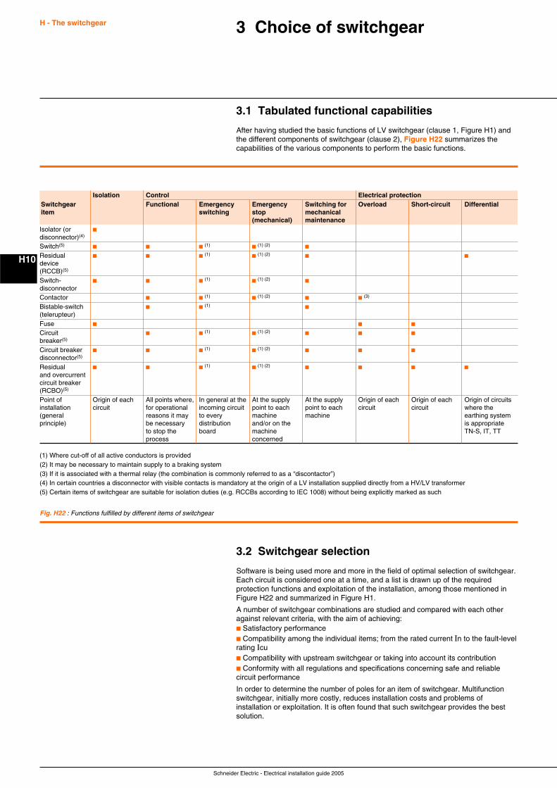
Schneider Electric - Electrical installation guide 2005
H - The switchgear
H10
3 Choice of switchgear
3.1 Tabulated functional capabilities
After having studied the basic functions of LV switchgear (clause 1, Figure H1) andthe different components of switchgear (clause 2), Figure H22 summarizes thecapabilities of the various components to perform the basic functions.
(1) Where cut-off of all active conductors is provided(2) It may be necessary to maintain supply to a braking system(3) If it is associated with a thermal relay (the combination is commonly referred to as a “discontactor”)(4) In certain countries a disconnector with visible contacts is mandatory at the origin of a LV installation supplied directly from a HV/LV transformer(5) Certain items of switchgear are suitable for isolation duties (e.g. RCCBs according to IEC 1008) without being explicitly marked as such
3.2 Switchgear selection
Software is being used more and more in the field of optimal selection of switchgear.Each circuit is considered one at a time, and a list is drawn up of the requiredprotection functions and exploitation of the installation, among those mentioned inFigure H22 and summarized in Figure H1.
A number of switchgear combinations are studied and compared with each otheragainst relevant criteria, with the aim of achieving:c Satisfactory performancec Compatibility among the individual items; from the rated current In to the fault-levelrating Icuc Compatibility with upstream switchgear or taking into account its contributionc Conformity with all regulations and specifications concerning safe and reliablecircuit performance
In order to determine the number of poles for an item of switchgear. Multifunctionswitchgear, initially more costly, reduces installation costs and problems ofinstallation or exploitation. It is often found that such switchgear provides the bestsolution.
Isolation Control Electrical protectionSwitchgear Functional Emergency Emergency Switching for Overload Short-circuit Differentialitem switching stop mechanical
(mechanical) maintenanceIsolator (or c
disconnector)(4)
Switch(5)c c c (1)
c (1) (2)c
Residual c c c (1)c (1) (2)
c c
device(RCCB)(5)
Switch- c c c (1)c (1) (2)
c
disconnectorContactor c c (1)
c (1) (2)c c (3)
Bistable-switch c c (1)c
(telerupteur)Fuse c c c
Circuit c c (1)c (1) (2)
c c c
breaker(5)
Circuit breaker c c c (1)c (1) (2)
c c c
disconnector(5)
Residual c c c (1)c (1) (2)
c c c c
and overcurrentcircuit breaker(RCBO)(5)
Point of Origin of each All points where, In general at the At the supply At the supply Origin of each Origin of each Origin of circuitsinstallation circuit for operational incoming circuit point to each point to each circuit circuit where the(general reasons it may to every machine machine earthing systemprinciple) be necessary distribution and/or on the is appropriate
to stop the board machine TN-S, IT, TTprocess concerned
Fig. H22 : Functions fulfilled by different items of switchgear
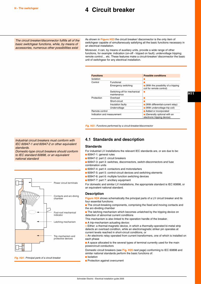
Schneider Electric - Electrical installation guide 2005
H11
4 Circuit breakerH - The switchgear
The circuit breaker/disconnector fulfills all of thebasic switchgear functions, while, by means ofaccessories, numerous other possibilities exist
As shown in Figure H23 the circuit breaker/ disconnector is the only item ofswitchgear capable of simultaneously satisfying all the basic functions necessary inan electrical installation.
Moreover, it can, by means of auxiliary units, provide a wide range of otherfunctions, for example: indication (on-off - tripped on fault); undervoltage tripping;remote control… etc. These features make a circuit-breaker/ disconnector the basicunit of switchgear for any electrical installation.
Fig. H23 : Functions performed by a circuit-breaker/disconnector
4.1 Standards and description
StandardsFor industrial LV installations the relevant IEC standards are, or are due to be:c 60947-1: general rulesc 60947-2: part 2: circuit breakersc 60947-3: part 3: switches, disconnectors, switch-disconnectors and fusecombination unitsc 60947-4: part 4: contactors and motorstartersc 60947-5: part 5: control-circuit devices and switching elementsc 60947-6: part 6: multiple function switching devicesc 60947-7: part 7: ancillary equipment
For domestic and similar LV installations, the appropriate standard is IEC 60898, oran equivalent national standard.
DescriptionFigure H24 shows schematically the principal parts of a LV circuit breaker and itsfour essential functions:c The circuit-breaking components, comprising the fixed and moving contacts andthe arc-dividing chamberc The latching mechanism which becomes unlatched by the tripping device ondetection of abnormal current conditionsThis mechanism is also linked to the operation handle of the breaker.c A trip-mechanism actuating device:v Either: a thermal-magnetic device, in which a thermally-operated bi-metal stripdetects an overload condition, while an electromagnetic striker pin operates atcurrent levels reached in short-circuit conditions, orv An electronic relay operated from current transformers, one of which is installed oneach phasec A space allocated to the several types of terminal currently used for the mainpowercircuit conductors
Domestic circuit breakers (see Fig. H25 next page) conforming to IEC 60898 andsimilar national standards perform the basic functions of:c Isolationc Protection against overcurrent
Power circuit terminals
Trip mechanism and protective devices
Latching mechanism
Contacts and arc-diving chamber
Fool-roof mechanical indicator
Fig. H24 : Principal parts of a circuit breaker
Industrial circuit breakers must conform withIEC 60947-1 and 60947-2 or other equivalentstandards.Domestic-type circuit breakers should conformto IEC standard 60898, or an equivalentnational standard
Functions Possible conditionsIsolation c
Control Functional c
Emergency switching c (With the possibility of a trippingcoil for remote control)
Switching-off for mechanical c
maintenanceProtection Overload c
Short-circuit c
Insulation faulty c (With differential-current relay)Undervoltage c (With undervoltage-trip coil)
Remote control c Added or incorporatedIndication and measurement c (Generally optional with an
electronic tripping device)
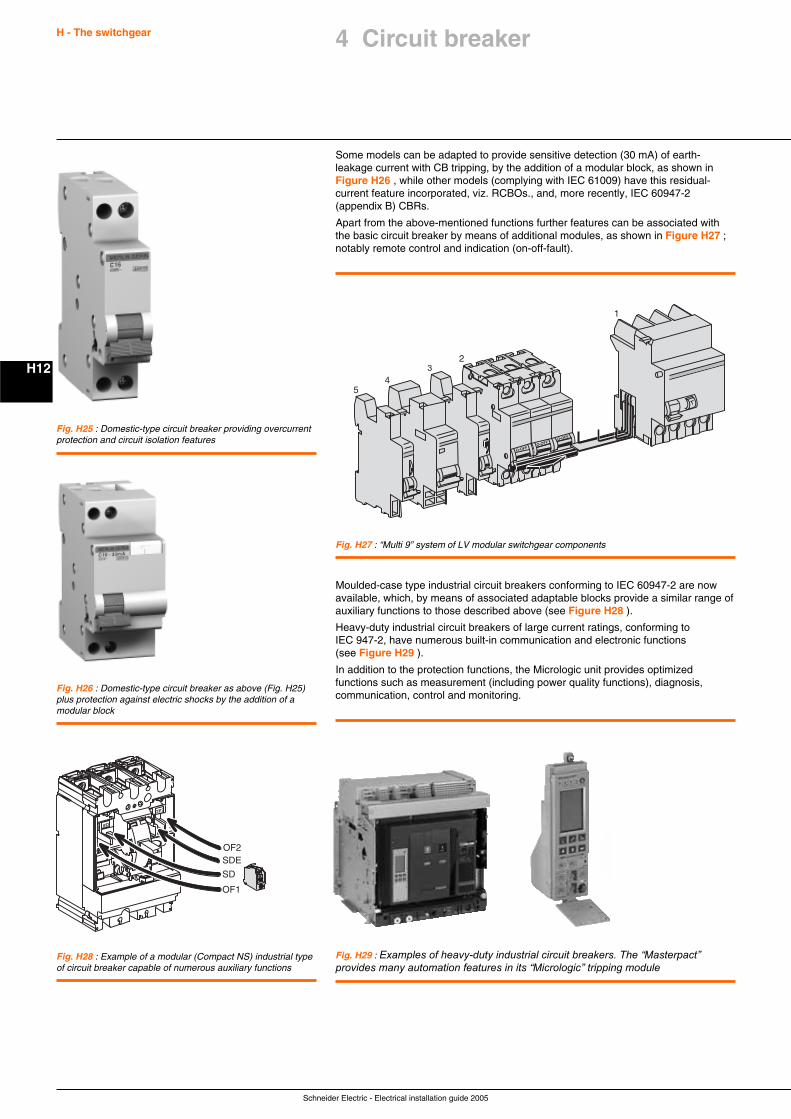
Schneider Electric - Electrical installation guide 2005
H - The switchgear
H12
Some models can be adapted to provide sensitive detection (30 mA) of earth-leakage current with CB tripping, by the addition of a modular block, as shown inFigure H26 , while other models (complying with IEC 61009) have this residual-current feature incorporated, viz. RCBOs., and, more recently, IEC 60947-2(appendix B) CBRs.
Apart from the above-mentioned functions further features can be associated withthe basic circuit breaker by means of additional modules, as shown in Figure H27 ;notably remote control and indication (on-off-fault).
O-OFF
O-OFF
O-OFF-
-
1
23
45
Fig. H27 : “Multi 9” system of LV modular switchgear components
Fig. H29 : Examples of heavy-duty industrial circuit breakers. The “Masterpact”provides many automation features in its “Micrologic” tripping module
Moulded-case type industrial circuit breakers conforming to IEC 60947-2 are nowavailable, which, by means of associated adaptable blocks provide a similar range ofauxiliary functions to those described above (see Figure H28 ).
Heavy-duty industrial circuit breakers of large current ratings, conforming toIEC 947-2, have numerous built-in communication and electronic functions(see Figure H29 ).
In addition to the protection functions, the Micrologic unit provides optimizedfunctions such as measurement (including power quality functions), diagnosis,communication, control and monitoring.
Fig. H25 : Domestic-type circuit breaker providing overcurrentprotection and circuit isolation features
Fig. H26 : Domestic-type circuit breaker as above (Fig. H25)plus protection against electric shocks by the addition of amodular block
SDE
OF1SD
OF2
OF2SDE
SD
OF1
Fig. H28 : Example of a modular (Compact NS) industrial typeof circuit breaker capable of numerous auxiliary functions
4 Circuit breaker
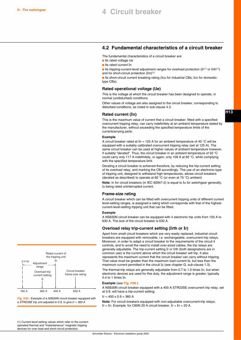
Schneider Electric - Electrical installation guide 2005
H - The switchgear
H13
4 Circuit breaker
4.2 Fundamental characteristics of a circuit breaker
The fundamental characteristics of a circuit breaker are:c Its rated voltage Uec Its rated current Inc Its tripping-current-level adjustment ranges for overload protection (Ir(1) or Irth(1))and for short-circuit protection (Im)(1)
c Its short-circuit current breaking rating (Icu for industrial CBs; Icn for domestic-type CBs).
Rated operational voltage (Ue)This is the voltage at which the circuit breaker has been designed to operate, innormal (undisturbed) conditions.
Other values of voltage are also assigned to the circuit breaker, corresponding todisturbed conditions, as noted in sub-clause 4.3.
Rated current (In)This is the maximum value of current that a circuit breaker, fitted with a specifiedovercurrent tripping relay, can carry indefinitely at an ambient temperature stated bythe manufacturer, without exceeding the specified temperature limits of thecurrentcarrying parts.
ExampleA circuit breaker rated at In = 125 A for an ambient temperature of 40 °C will beequipped with a suitably calibrated overcurrent tripping relay (set at 125 A). Thesame circuit breaker can be used at higher values of ambient temperature however,if suitably “derated”. Thus, the circuit breaker in an ambient temperature of 50 °Ccould carry only 117 A indefinitely, or again, only 109 A at 60 °C, while complyingwith the specified temperature limit.
Derating a circuit breaker is achieved therefore, by reducing the trip-current settingof its overload relay, and marking the CB accordingly. The use of an electronic-typeof tripping unit, designed to withstand high temperatures, allows circuit breakers(derated as described) to operate at 60 °C (or even at 70 °C) ambient.
Note: In for circuit breakers (in IEC 60947-2) is equal to Iu for switchgear generally,Iu being rated uninterrupted current.
Frame-size ratingA circuit breaker which can be fitted with overcurrent tripping units of different currentlevel-setting ranges, is assigned a rating which corresponds with that of the highestcurrent-level-setting tripping unit that can be fitted.
ExampleA NS630N circuit breaker can be equipped with 4 electronic trip units from 150 A to630 A. The size of the circuit breaker is 630 A.
Overload relay trip-current setting (Irth or Ir)Apart from small circuit breakers which are very easily replaced, industrial circuitbreakers are equipped with removable, i.e. exchangeable, overcurrent-trip relays.Moreover, in order to adapt a circuit breaker to the requirements of the circuit itcontrols, and to avoid the need to install over-sized cables, the trip relays aregenerally adjustable. The trip-current setting Ir or Irth (both designations are incommon use) is the current above which the circuit breaker will trip. It alsorepresents the maximum current that the circuit breaker can carry without tripping.That value must be greater than the maximum load current IB, but less than themaximum current permitted in the circuit Iz (see chapter G, sub-clause 1.3).
The thermal-trip relays are generally adjustable from 0.7 to 1.0 times In, but whenelectronic devices are used for this duty, the adjustment range is greater; typically0.4 to 1 times In.
Example (see Fig. H30 )A NS630N circuit breaker equipped with a 400 A STR23SE overcurrent trip relay, setat 0.9, will have a trip-current setting:
Ir = 400 x 0.9 = 360 A
Note: For circuit breakers equipped with non-adjustable overcurrent-trip relays,Ir = In. Example: for C60N 20 A circuit breaker, Ir = In = 20 A.
(1) Current-level setting values which refer to the current-operated thermal and “instantaneous” magnetic trippingdevices for over-load and short-circuit protection.
0.4 In
160 A 360 A 400 A 630 A
Rated current ofthe tripping unit
In
Overload tripcurrent setting
Ir
Adjustmentrange
Circuit breakerframe-size rating
Fig. H30 : Example of a NS630N circuit breaker equipped witha STR23SE trip unit adjusted to 0.9, to give Ir = 360 A
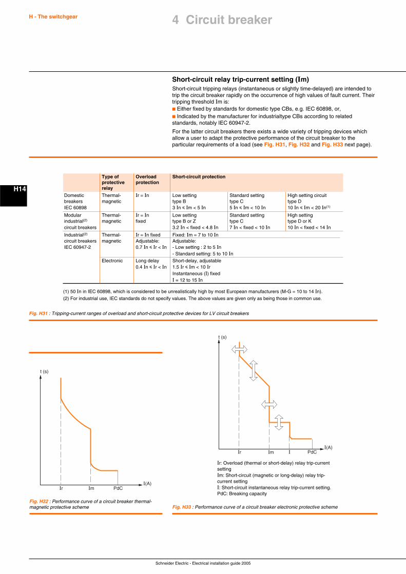
Schneider Electric - Electrical installation guide 2005
H - The switchgear
H14
Short-circuit relay trip-current setting (Im)Short-circuit tripping relays (instantaneous or slightly time-delayed) are intended totrip the circuit breaker rapidly on the occurrence of high values of fault current. Theirtripping threshold Im is:c Either fixed by standards for domestic type CBs, e.g. IEC 60898, or,c Indicated by the manufacturer for industrialtype CBs according to relatedstandards, notably IEC 60947-2.
For the latter circuit breakers there exists a wide variety of tripping devices whichallow a user to adapt the protective performance of the circuit breaker to theparticular requirements of a load (see Fig. H31, Fig. H32 and Fig. H33 next page).
Fig. H31 : Tripping-current ranges of overload and short-circuit protective devices for LV circuit breakers
I(A)Im
t (s)
Ir PdCI
Fig. H33 : Performance curve of a circuit breaker electronic protective scheme
Ir: Overload (thermal or short-delay) relay trip-currentsettingIm: Short-circuit (magnetic or long-delay) relay trip-current settingI: Short-circuit instantaneous relay trip-current setting.PdC: Breaking capacity
I(A)Im
t (s)
Ir PdC
Fig. H32 : Performance curve of a circuit breaker thermal-magnetic protective scheme
(1) 50 In in IEC 60898, which is considered to be unrealistically high by most European manufacturers (M-G = 10 to 14 In).
(2) For industrial use, IEC standards do not specify values. The above values are given only as being those in common use.
Type of Overload Short-circuit protectionprotective protectionrelay
Domestic Thermal- Ir = In Low setting Standard setting High setting circuitbreakers magnetic type B type C type DIEC 60898 3 In i Im < 5 In 5 In i Im < 10 In 10 In i Im < 20 In(1)
Modular Thermal- Ir = In Low setting Standard setting High settingindustrial(2) magnetic fixed type B or Z type C type D or Kcircuit breakers 3.2 In < fixed < 4.8 In 7 In < fixed < 10 In 10 In < fixed < 14 InIndustrial(2) Thermal- Ir = In fixed Fixed: Im = 7 to 10 Incircuit breakers magnetic Adjustable: Adjustable:IEC 60947-2 0.7 In i Ir < In - Low setting : 2 to 5 In
- Standard setting: 5 to 10 InElectronic Long delay Short-delay, adjustable
0.4 In i Ir < In 1.5 Ir i Im < 10 IrInstantaneous (I) fixedI = 12 to 15 In
4 Circuit breaker
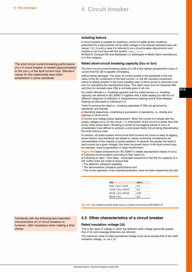
Schneider Electric - Electrical installation guide 2005
H - The switchgear
H15
Isolating featureA circuit breaker is suitable for isolating a circuit if it fulfills all the conditionsprescribed for a disconnector (at its rated voltage) in the relevant standard (see sub-clause 1.2). In such a case it is referred to as a circuit breaker-disconnector andmarked on its front face with the symbol All Multi 9, Compact NS and Masterpact LV switchgear of Merlin Gerin manufactureis in this category.
Rated short-circuit breaking capacity (Icu or Icn)
The short-circuit current-breaking rating of a CB is the highest (prospective) value ofcurrent that the CB is capable of breaking.
without being damaged. The value of current quoted in the standards is the rmsvalue of the AC component of the fault current, i.e. the DC transient component(which is always present in the worst possible case of short-circuit) is assumed to bezero for calculating the standardized value. This rated value (Icu) for industrial CBsand (Icn) for domestic-type CBs is normally given in kA rms.
Icu (rated ultimate s.c. breaking capacity) and Ics (rated service s.c. breakingcapacity) are defined in IEC 60947-2 together with a table relating Ics with Icu fordifferent categories of utilization A (instantaneous tripping) and B (time-delayedtripping) as discussed in subclause 4.3.
Tests for proving the rated s.c. breaking capacities of CBs are governed bystandards, and include:c Operating sequences, comprising a succession of operations, i.e. closing andopening on short-circuitc Current and voltage phase displacement. When the current is in phase with thesupply voltage (cos ϕ for the circuit = 1), interruption of the current is easier than thatat any other power factor. Breaking a current at low lagging values of cos ϕ isconsiderably more difficult to achieve; a zero power-factor circuit being (theoretically)the most onerous case
In practice, all power-system short-circuit fault currents are (more-or-less) at laggingpower factors, and standards are based on values commonly considered to berepresentative of the majority of power systems. In general, the greater the level offault current (at a given voltage), the lower the power factor of the fault-current loop,for example, close to generators or large transformers.
Figure H34 below extracted from IEC 60947-2 relates standardized values of cos ϕto industrial circuit breakers according to their rated Icu.c Following an open - time delay - close/open sequence to test the Icu capacity of aCB, further tests are made to ensure thatv The dielectric withstand capabilityv The disconnection (isolation) performance andv The correct operation of the overload protection, have not been impaired by the test
4.3 Other characteristics of a circuit breaker
Rated insulation voltage (Ui)This is the value of voltage to which the dielectric tests voltage (generally greaterthan 2 Ui) and creepage distances are referred.
The maximum value of rated operational voltage must never exceed that of the ratedinsulation voltage, i.e. Ue i Ui.
Familiarity with the following less-importantcharacteristics of LV circuit breakers is,however, often necessary when making a finalchoice.
4 Circuit breaker
The short-circuit current-breaking performanceof a LV circuit breaker is related (approximately)to the cos ϕ of the fault-current loop. Standardvalues for this relationship have beenestablished in some standards
Icu cos ϕ6 kA < Icu i 10 kA 0.5
10 kA < Icu i 20 kA 0.3
20 kA < Icu i 50 kA 0.25
50 kA < Icu 0.2
Fig. H34 : Icu related to power factor (cos ϕ) of fault-current circuit (IEC 60947-2)
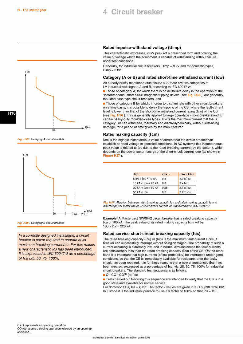
Schneider Electric - Electrical installation guide 2005
H - The switchgear
H16
Rated impulse-withstand voltage (Uimp)This characteristic expresses, in kV peak (of a prescribed form and polarity) thevalue of voltage which the equipment is capable of withstanding without failure,under test conditions.
Generally, for industrial circuit breakers, Uimp = 8 kV and for domestic types,Uimp = 6 kV.
Category (A or B) and rated short-time withstand current (Icw)As already briefly mentioned (sub-clause 4.2) there are two categories ofLV industrial switchgear, A and B, according to IEC 60947-2:c Those of category A, for which there is no deliberate delay in the operation of the“instantaneous” short-circuit magnetic tripping device (see Fig. H35 ), are generallymoulded-case type circuit breakers, andc Those of category B for which, in order to discriminate with other circuit breakerson a time basis, it is possible to delay the tripping of the CB, where the fault-currentlevel is lower than that of the short-time withstand current rating (Icw) of the CB(see Fig. H36 ). This is generally applied to large open-type circuit breakers and tocertain heavy-duty moulded-case types. Icw is the maximum current that the Bcategory CB can withstand, thermally and electrodynamically, without sustainingdamage, for a period of time given by the manufacturer
Rated making capacity (Icm)Icm is the highest instantaneous value of current that the circuit breaker canestablish at rated voltage in specified conditions. In AC systems this instantaneouspeak value is related to Icu (i.e. to the rated breaking current) by the factor k, whichdepends on the power factor (cos ϕ) of the short-circuit current loop (as shown inFigure H37 ).
In a correctly designed installation, a circuitbreaker is never required to operate at itsmaximum breaking current Icu. For this reasona new characteristic Ics has been introduced.It is expressed in IEC 60947-2 as a percentageof Icu (25, 50, 75, 100%)
Icu cos ϕ Icm = kIcu
6 kA < Icu i 10 kA 0.5 1.7 x Icu
10 kA < Icu i 20 kA 0.3 2 x Icu
20 kA < Icu i 50 kA 0.25 2.1 x Icu
50 kA i Icu 0.2 2.2 x Icu
Fig. H37 : Relation between rated breaking capacity Icu and rated making capacity Icm atdifferent power-factor values of short-circuit current, as standardized in IEC 60947-2
Example: A Masterpact NW08H2 circuit breaker has a rated breaking capacityIcu of 100 kA. The peak value of its rated making capacity Icm will be100 x 2.2 = 220 kA.
Rated service short-circuit breaking capacity (Ics)The rated breaking capacity (Icu) or (Icn) is the maximum fault-current a circuitbreaker can successfully interrupt without being damaged. The probability of such acurrent occurring is extremely low, and in normal circumstances the fault-currentsare considerably less than the rated breaking capacity (Icu) of the CB. On the otherhand it is important that high currents (of low probability) be interrupted under goodconditions, so that the CB is immediately available for reclosure, after the faultycircuit has been repaired. It is for these reasons that a new characteristic (Ics) hasbeen created, expressed as a percentage of Icu, viz: 25, 50, 75, 100% for industrialcircuit breakers. The standard test sequence is as follows:c O - CO - CO(1) (at Ics)c Tests carried out following this sequence are intended to verify that the CB is in agood state and available for normal serviceFor domestic CBs, Ics = k Icn. The factor k values are given in IEC 60898 table XIV.In Europe it is the industrial practice to use a k factor of 100% so that Ics = Icu.
(1) O represents an opening operation.CO represents a closing operation followed by an opening)operation.
I(A)Im
t (s)
Fig. H35 : Category A circuit breaker
I(A)Im
t (s)
PdCIcwI
Fig. H36 : Category B circuit breaker
4 Circuit breaker
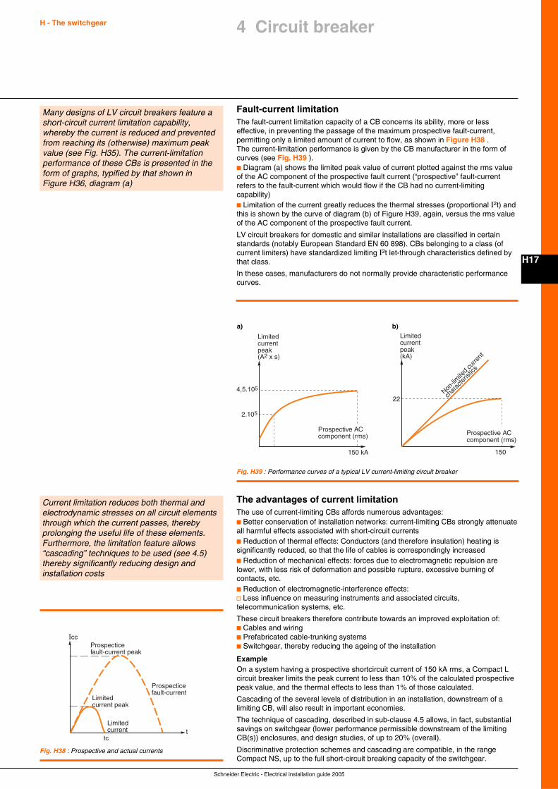
Schneider Electric - Electrical installation guide 2005
H - The switchgear
H17
4 Circuit breaker
Fault-current limitationThe fault-current limitation capacity of a CB concerns its ability, more or lesseffective, in preventing the passage of the maximum prospective fault-current,permitting only a limited amount of current to flow, as shown in Figure H38 .The current-limitation performance is given by the CB manufacturer in the form ofcurves (see Fig. H39 ).c Diagram (a) shows the limited peak value of current plotted against the rms valueof the AC component of the prospective fault current (“prospective” fault-currentrefers to the fault-current which would flow if the CB had no current-limitingcapability)c Limitation of the current greatly reduces the thermal stresses (proportional I2t) andthis is shown by the curve of diagram (b) of Figure H39, again, versus the rms valueof the AC component of the prospective fault current.
LV circuit breakers for domestic and similar installations are classified in certainstandards (notably European Standard EN 60 898). CBs belonging to a class (ofcurrent limiters) have standardized limiting I2t let-through characteristics defined bythat class.
In these cases, manufacturers do not normally provide characteristic performancecurves.
Many designs of LV circuit breakers feature ashort-circuit current limitation capability,whereby the current is reduced and preventedfrom reaching its (otherwise) maximum peakvalue (see Fig. H35). The current-limitationperformance of these CBs is presented in theform of graphs, typified by that shown inFigure H36, diagram (a)
Limited current peak (kA)
Non-lim
ited
curre
nt
char
acte
ristic
s
150
22
Prospective AC component (rms)
a)
150 kA
Limited current peak(A2 x s)
2.105
4,5.105
Prospective AC component (rms)
b)
Fig. H39 : Performance curves of a typical LV current-limiting circuit breaker
Current limitation reduces both thermal andelectrodynamic stresses on all circuit elementsthrough which the current passes, therebyprolonging the useful life of these elements.Furthermore, the limitation feature allows“cascading” techniques to be used (see 4.5)thereby significantly reducing design andinstallation costs
The advantages of current limitationThe use of current-limiting CBs affords numerous advantages:c Better conservation of installation networks: current-limiting CBs strongly attenuateall harmful effects associated with short-circuit currentsc Reduction of thermal effects: Conductors (and therefore insulation) heating issignificantly reduced, so that the life of cables is correspondingly increasedc Reduction of mechanical effects: forces due to electromagnetic repulsion arelower, with less risk of deformation and possible rupture, excessive burning ofcontacts, etc.c Reduction of electromagnetic-interference effects:v Less influence on measuring instruments and associated circuits,telecommunication systems, etc.
These circuit breakers therefore contribute towards an improved exploitation of:c Cables and wiringc Prefabricated cable-trunking systemsc Switchgear, thereby reducing the ageing of the installation
ExampleOn a system having a prospective shortcircuit current of 150 kA rms, a Compact Lcircuit breaker limits the peak current to less than 10% of the calculated prospectivepeak value, and the thermal effects to less than 1% of those calculated.
Cascading of the several levels of distribution in an installation, downstream of alimiting CB, will also result in important economies.
The technique of cascading, described in sub-clause 4.5 allows, in fact, substantialsavings on switchgear (lower performance permissible downstream of the limitingCB(s)) enclosures, and design studies, of up to 20% (overall).
Discriminative protection schemes and cascading are compatible, in the rangeCompact NS, up to the full short-circuit breaking capacity of the switchgear.
Fig. H38 : Prospective and actual currents
Icc
t
Limited current peak
Limited current
tc
Prospectice fault-current
Prospectice fault-current peak
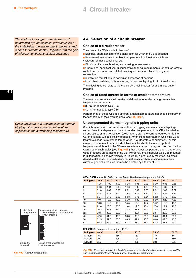
Schneider Electric - Electrical installation guide 2005
H - The switchgear
H18
4.4 Selection of a circuit breaker
Choice of a circuit breakerThe choice of a CB is made in terms of:c Electrical characteristics of the installation for which the CB is destinedc Its eventual environment: ambient temperature, in a kiosk or switchboardenclosure, climatic conditions, etc.c Short-circuit current breaking and making requirementsc Operational specifications: Discriminative tripping, requirements (or not) for remotecontrol and indication and related auxiliary contacts, auxiliary tripping coils,connectionc Installation regulations; in particular: Protection of personsc Load characteristics, such as motors, fluorescent lighting, LV/LV transformers
The following notes relate to the choice LV circuit breaker for use in distributionsystems.
Choice of rated current in terms of ambient temperatureThe rated current of a circuit breaker is defined for operation at a given ambienttemperature, in general:c 30 °C for domestic-type CBsc 40 °C for industrial-type CBs
Performance of these CBs in a different ambient temperature depends principally onthe technology of their tripping units (see Fig. H40 ).
Uncompensated thermalmagnetic tripping unitsCircuit breakers with uncompensated thermal tripping elements have a tripping-current level that depends on the surrounding temperature. If the CB is installed inan enclosure, or in a hot location (boiler room, etc.), the current required to trip theCB on overload will be sensibly reduced. When the temperature in which the CB islocated exceeds its reference temperature, it will therefore be “derated”. For thisreason, CB manufacturers provide tables which indicate factors to apply attemperatures different to the CB reference temperature. It may be noted from typicalexamples of such tables (see Fig. H41 ) that a lower temperature than the referencevalue produces an up-rating of the CB. Moreover, small modular-type CBs mountedin juxtaposition, as shown typically in Figure H27, are usually mounted in a smallclosed metal case. In this situation, mutual heating, when passing normal loadcurrents, generally requires them to be derated by a factor of 0.8.
The choice of a range of circuit breakers isdetermined by: the electrical characteristics ofthe installation, the environment, the loads anda need for remote control, together with the typeof telecommunications system envisaged
Ambient temperature
Single CBin free air
Circuit breakers installed in an enclosure
Ambient temperature
Temperature of airsurrouding the
circuit breakers
Fig. H40 : Ambient temperature
Circuit breakers with uncompensated thermaltripping units have a trip current level thatdepends on the surrounding temperature
C60a, C60H: curve C. C60N: curves B and C (reference temperature: 30 °C)Rating (A) 20 °C 25 °C 30 °C 35 °C 40 °C 45 °C 50 °C 55 °C 60 °C1 1.05 1.02 1.00 0.98 0.95 0.93 0.90 0.88 0.852 2.08 2.04 2.00 1.96 1.92 1.88 1.84 1.80 1.743 3.18 3.09 3.00 2.91 2.82 2.70 2.61 2.49 2.374 4.24 4.12 4.00 3.88 3.76 3.64 3.52 3.36 3.246 6.24 6.12 6.00 5.88 5.76 5.64 5.52 5.40 5.3010 10.6 10.3 10.0 9.70 9.30 9.00 8.60 8.20 7.8016 16.8 16.5 16.0 15.5 15.2 14.7 14.2 13.8 13.520 21.0 20.6 20.0 19.4 19.0 18.4 17.8 17.4 16.825 26.2 25.7 25.0 24.2 23.7 23.0 22.2 21.5 20.732 33.5 32.9 32.0 31.4 30.4 29.8 28.4 28.2 27.540 42.0 41.2 40.0 38.8 38.0 36.8 35.6 34.4 33.250 52.5 51.5 50.0 48.5 47.4 45.5 44.0 42.5 40.563 66.2 64.9 63.0 61.1 58.0 56.7 54.2 51.7 49.2
NS250N/H/L (reference temperature: 40 °C)Rating (A) 40 °C 45 °C 50 °C 55 °C 60 °CTM160D 160 156 152 147 144TM200D 200 195 190 185 180TM250D 250 244 238 231 225
Fig. H41 : Examples of tables for the determination of derating/uprating factors to apply to CBswith uncompensated thermal tripping units, according to temperature
4 Circuit breaker
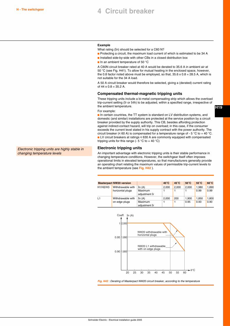
Schneider Electric - Electrical installation guide 2005
H - The switchgear
H19
4 Circuit breaker
ExampleWhat rating (In) should be selected for a C60 N?c Protecting a circuit, the maximum load current of which is estimated to be 34 Ac Installed side-by-side with other CBs in a closed distribution boxc In an ambient temperature of 50 °C
A C60N circuit breaker rated at 40 A would be derated to 35.6 A in ambient air at50 °C (see Fig. H41). To allow for mutual heating in the enclosed space, however,the 0.8 factor noted above must be employed, so that, 35.6 x 0.8 = 28.5 A, which isnot suitable for the 34 A load.
A 50 A circuit breaker would therefore be selected, giving a (derated) current ratingof 44 x 0.8 = 35.2 A.
Compensated thermal-magnetic tripping unitsThese tripping units include a bi-metal compensating strip which allows the overloadtrip-current setting (Ir or Irth) to be adjusted, within a specified range, irrespective ofthe ambient temperature.
For example:c In certain countries, the TT system is standard on LV distribution systems, anddomestic (and similar) installations are protected at the service position by a circuitbreaker provided by the supply authority. This CB, besides affording protectionagainst indirect-contact hazard, will trip on overload; in this case, if the consumerexceeds the current level stated in his supply contract with the power authority. Thecircuit breaker (i 60 A) is compensated for a temperature range of - 5 °C to + 40 °C.c LV circuit breakers at ratings i 630 A are commonly equipped with compensatedtripping units for this range (- 5 °C to + 40 °C)
Electronic tripping unitsAn important advantage with electronic tripping units is their stable performance inchanging temperature conditions. However, the switchgear itself often imposesoperational limits in elevated temperatures, so that manufacturers generally providean operating chart relating the maximum values of permissible trip-current levels tothe ambient temperature (see Fig. H42 ).
Electronic tripping units are highly stable inchanging temperature levels
Masterpact NW20 version 40°C 45°C 50°C 55°C 60°CH1/H2/H3 Withdrawable with In (A) 2,000 2,000 2,000 1,980 1,890
horizontal plugs Maximum 1 1 1 0.99 0.99adjustment Ir
L1 Withdrawable with In (A) 2,000 200 1,900 1,850 1,800on edge plugs Maximum 1 1 0.95 0.93 0.90
adjustment Ir
In (A)Coeff.
2,0001
NW20 withdrawable with horizontal plugs
NW20 L1 withdrawable with on edge plugs
1,8900.95
1,8000.90
20 50 55 6035 40 4525 30θ°C
Fig. H42 : Derating of Masterpact NW20 circuit breaker, according to the temperature
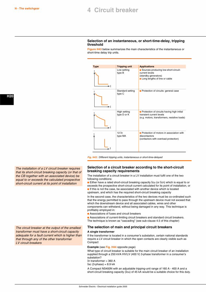
Schneider Electric - Electrical installation guide 2005
H - The switchgear
H20
Selection of an instantaneous, or short-time-delay, trippingthresholdFigure H43 below summarizes the main characteristics of the instantaneous orshort-time delay trip units.
Selection of a circuit breaker according to the short-circuitbreaking capacity requirementsThe installation of a circuit breaker in a LV installation must fulfil one of the twofollowing conditions:c Either have a rated short-circuit breaking capacity Icu (or Icn) which is equal to orexceeds the prospective short-circuit current calculated for its point of installation, orc If this is not the case, be associated with another device which is locatedupstream, and which has the required short-circuit breaking capacity
In the second case, the characteristics of the two devices must be co-ordinated suchthat the energy permitted to pass through the upstream device must not exceed thatwhich the downstream device and all associated cables, wires and othercomponents can withstand, without being damaged in any way. This technique isprofitably employed in:c Associations of fuses and circuit breakersc Associations of current-limiting circuit breakers and standard circuit breakers.The technique is known as “cascading” (see sub-clause 4.5 of this chapter)
The selection of main and principal circuit breakersA single transformerIf the transformer is located in a consumer’s substation, certain national standardsrequire a LV circuit breaker in which the open contacts are clearly visible such asCompact
Example (see Fig. H44 opposite page)What type of circuit breaker is suitable for the main circuit breaker of an installationsupplied through a 250 kVA HV/LV (400 V) 3-phase transformer in a consumer’ssubstation?In transformer = 360 AIsc (3-phase) = 8.9 kA
A Compact NS400N with an adjustable tripping-unit range of 160 A - 400 A and ashort-circuit breaking capacity (Icu) of 45 kA would be a suitable choice for this duty.
The installation of a LV circuit breaker requiresthat its short-circuit breaking capacity (or that ofthe CB together with an associated device) beequal to or exceeds the calculated prospectiveshort-circuit current at its point of installation
The circuit breaker at the output of the smallesttransformer must have a short-circuit capacityadequate for a fault current which is higher thanthat through any of the other transformerLV circuit breakers
Fig. H43 : Different tripping units, instantaneous or short-time-delayed
Type Tripping unit ApplicationsLow setting c Sources producing low-short-circuit-type B current levels
(standby generators)c Long lengths of line or cable
Standard setting c Protection of circuits: general casetype C
High setting c Protection of circuits having high initialtype D or K transient current levels
(e.g. motors, transformers, resistive loads)
12 In c Protection of motors in association withtype MA discontactors
(contactors with overload protection)
I
t
I
t
I
t
I
t
4 Circuit breaker
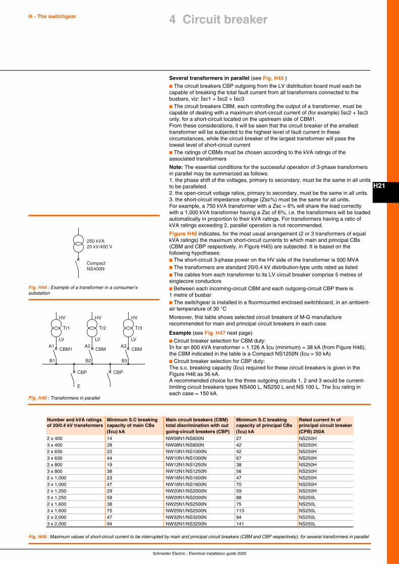
Schneider Electric - Electrical installation guide 2005
H - The switchgear
H21
Several transformers in parallel (see Fig. H45 )
c The circuit breakers CBP outgoing from the LV distribution board must each becapable of breaking the total fault current from all transformers connected to thebusbars, viz: Isc1 + Isc2 + Isc3c The circuit breakers CBM, each controlling the output of a transformer, must becapable of dealing with a maximum short-circuit current of (for example) Isc2 + Isc3only, for a short-circuit located on the upstream side of CBM1.From these considerations, it will be seen that the circuit breaker of the smallesttransformer will be subjected to the highest level of fault current in thesecircumstances, while the circuit breaker of the largest transformer will pass thelowest level of short-circuit currentc The ratings of CBMs must be chosen according to the kVA ratings of theassociated transformers
Note: The essential conditions for the successful operation of 3-phase transformersin parallel may be summarized as follows:1. the phase shift of the voltages, primary to secondary, must be the same in all unitsto be paralleled.2. the open-circuit voltage ratios, primary to secondary, must be the same in all units.3. the short-circuit impedance voltage (Zsc%) must be the same for all units.For example, a 750 kVA transformer with a Zsc = 6% will share the load correctlywith a 1,000 kVA transformer having a Zsc of 6%, i.e. the transformers will be loadedautomatically in proportion to their kVA ratings. For transformers having a ratio ofkVA ratings exceeding 2, parallel operation is not recommended.
Figure H46 indicates, for the most usual arrangement (2 or 3 transformers of equalkVA ratings) the maximum short-circuit currents to which main and principal CBs(CBM and CBP respectively, in Figure H45) are subjected. It is based on thefollowing hypotheses:c The short-circuit 3-phase power on the HV side of the transformer is 500 MVAc The transformers are standard 20/0.4 kV distribution-type units rated as listedc The cables from each transformer to its LV circuit breaker comprise 5 metres ofsinglecore conductorsc Between each incoming-circuit CBM and each outgoing-circuit CBP there is1 metre of busbarc The switchgear is installed in a floormounted enclosed switchboard, in an ambient-air temperature of 30 °C
Moreover, this table shows selected circuit breakers of M-G manufacturerecommended for main and principal circuit breakers in each case.
Example (see Fig. H47 next page)
c Circuit breaker selection for CBM duty:In for an 800 kVA transformer = 1.126 A Icu (minimum) = 38 kA (from Figure H46),the CBM indicated in the table is a Compact NS1250N (Icu = 50 kA)c Circuit breaker selection for CBP duty:The s.c. breaking capacity (Icu) required for these circuit breakers is given in theFigure H46 as 56 kA.A recommended choice for the three outgoing circuits 1, 2 and 3 would be current-limiting circuit breakers types NS400 L, NS250 L and NS 100 L. The Icu rating ineach case = 150 kA.
CompactNS400N
250 kVA20 kV/400 V
HV
Tr1
LV
CBM1A1
B1
CBP
HV
Tr2
LV
CBMA2
B2
CBP
HV
Tr3
LV
CBMA3
B3
E
Fig. H44 : Example of a transformer in a consumer’ssubstation
Fig. H45 : Transformers in parallel
4 Circuit breaker
Fig. H46 : Maximum values of short-circuit current to be interrupted by main and principal circuit breakers (CBM and CBP respectively), for several transformers in parallel
Number and kVA ratings Minimum S.C breaking Main circuit breakers (CBM) Minimum S.C breaking Rated current In ofof 20/0.4 kV transformers capacity of main CBs total discrimination with out capacity of principal CBs principal circuit breaker
(Icu) kA going-circuit breakers (CBP) (Icu) kA (CPB) 250A2 x 400 14 NW08N1/NS800N 27 NS250H3 x 400 28 NW08N1/NS800N 42 NS250H2 x 630 22 NW10N1/NS1000N 42 NS250H3 x 630 44 NW10N1/NS1000N 67 NS250H2 x 800 19 NW12N1/NS1250N 38 NS250H3 x 800 38 NW12N1/NS1250N 56 NS250H2 x 1,000 23 NW16N1/NS1600N 47 NS250H3 x 1,000 47 NW16N1/NS1600N 70 NS250H2 x 1,250 29 NW20N1/NS2000N 59 NS250H3 x 1,250 59 NW20N1/NS2000N 88 NS250L2 x 1,600 38 NW25N1/NS2500N 75 NS250L3 x 1,600 75 NW25N1/NS2500N 113 NS250L2 x 2,000 47 NW32N1/NS3200N 94 NS250L3 x 2,000 94 NW32N1/NS3200N 141 NS250L
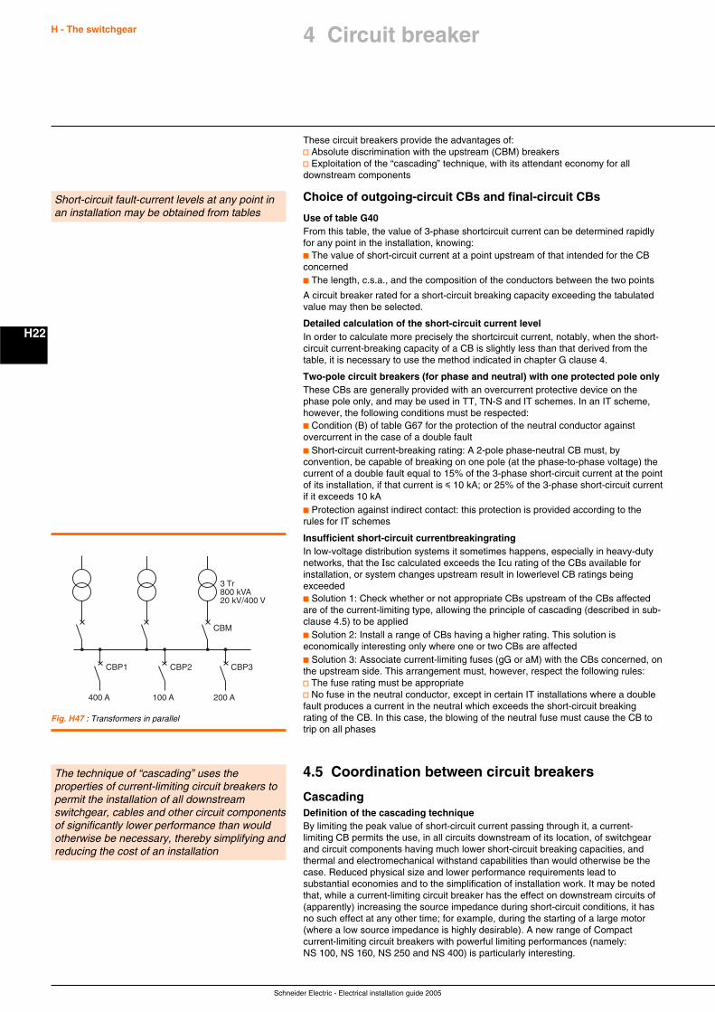
Schneider Electric - Electrical installation guide 2005
H - The switchgear
H22
These circuit breakers provide the advantages of:v Absolute discrimination with the upstream (CBM) breakersv Exploitation of the “cascading” technique, with its attendant economy for alldownstream components
Choice of outgoing-circuit CBs and final-circuit CBs
Use of table G40From this table, the value of 3-phase shortcircuit current can be determined rapidlyfor any point in the installation, knowing:c The value of short-circuit current at a point upstream of that intended for the CBconcernedc The length, c.s.a., and the composition of the conductors between the two points
A circuit breaker rated for a short-circuit breaking capacity exceeding the tabulatedvalue may then be selected.
Detailed calculation of the short-circuit current levelIn order to calculate more precisely the shortcircuit current, notably, when the short-circuit current-breaking capacity of a CB is slightly less than that derived from thetable, it is necessary to use the method indicated in chapter G clause 4.
Two-pole circuit breakers (for phase and neutral) with one protected pole onlyThese CBs are generally provided with an overcurrent protective device on thephase pole only, and may be used in TT, TN-S and IT schemes. In an IT scheme,however, the following conditions must be respected:c Condition (B) of table G67 for the protection of the neutral conductor againstovercurrent in the case of a double faultc Short-circuit current-breaking rating: A 2-pole phase-neutral CB must, byconvention, be capable of breaking on one pole (at the phase-to-phase voltage) thecurrent of a double fault equal to 15% of the 3-phase short-circuit current at the pointof its installation, if that current is i 10 kA; or 25% of the 3-phase short-circuit currentif it exceeds 10 kAc Protection against indirect contact: this protection is provided according to therules for IT schemes
Insufficient short-circuit currentbreakingratingIn low-voltage distribution systems it sometimes happens, especially in heavy-dutynetworks, that the Isc calculated exceeds the Icu rating of the CBs available forinstallation, or system changes upstream result in lowerlevel CB ratings beingexceededc Solution 1: Check whether or not appropriate CBs upstream of the CBs affectedare of the current-limiting type, allowing the principle of cascading (described in sub-clause 4.5) to be appliedc Solution 2: Install a range of CBs having a higher rating. This solution iseconomically interesting only where one or two CBs are affectedc Solution 3: Associate current-limiting fuses (gG or aM) with the CBs concerned, onthe upstream side. This arrangement must, however, respect the following rules:v The fuse rating must be appropriatev No fuse in the neutral conductor, except in certain IT installations where a doublefault produces a current in the neutral which exceeds the short-circuit breakingrating of the CB. In this case, the blowing of the neutral fuse must cause the CB totrip on all phases
4.5 Coordination between circuit breakers
CascadingDefinition of the cascading techniqueBy limiting the peak value of short-circuit current passing through it, a current-limiting CB permits the use, in all circuits downstream of its location, of switchgearand circuit components having much lower short-circuit breaking capacities, andthermal and electromechanical withstand capabilities than would otherwise be thecase. Reduced physical size and lower performance requirements lead tosubstantial economies and to the simplification of installation work. It may be notedthat, while a current-limiting circuit breaker has the effect on downstream circuits of(apparently) increasing the source impedance during short-circuit conditions, it hasno such effect at any other time; for example, during the starting of a large motor(where a low source impedance is highly desirable). A new range of Compactcurrent-limiting circuit breakers with powerful limiting performances (namely:NS 100, NS 160, NS 250 and NS 400) is particularly interesting.
Short-circuit fault-current levels at any point inan installation may be obtained from tables
The technique of “cascading” uses theproperties of current-limiting circuit breakers topermit the installation of all downstreamswitchgear, cables and other circuit componentsof significantly lower performance than wouldotherwise be necessary, thereby simplifying andreducing the cost of an installation
CBP1
3 Tr800 kVA20 kV/400 V
CBM
400 A
CBP2
100 A
CBP3
200 A
Fig. H47 : Transformers in parallel
4 Circuit breaker
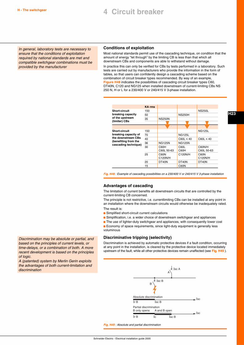
Schneider Electric - Electrical installation guide 2005
H - The switchgear
H23
4 Circuit breaker
Conditions of exploitationMost national standards permit use of the cascading technique, on condition that theamount of energy “let through” by the limiting CB is less than that which alldownstream CBs and components are able to withstand without damage.
In practice this can only be verified for CBs by tests performed in a laboratory. Suchtests are carried out by manufacturers who provide the information in the form oftables, so that users can confidently design a cascading scheme based on thecombination of circuit breaker types recommended. By way of an example,Figure H48 indicates the possibilities of cascading circuit breaker types C60,DT40N, C120 and NG125 when installed downstream of current-limiting CBs NS250 N, H or L for a 230/400 V or 240/415 V 3-phase installation.
In general, laboratory tests are necessary toensure that the conditions of exploitationrequired by national standards are met andcompatible switchgear combinations must beprovided by the manufacturer
Fig. H48 : Example of cascading possibilities on a 230/400 V or 240/415 V 3-phase installation
KA rmsShort-circuit 150 NS250Lbreaking capacity 50 NS250Hof the upstream 35 NS250N(limiter) CBs
Short-circuit 150 NG125Lbreaking capacity of 70 NG125Lthe downstream CBs 40 C60L i 40 C60L i 40(benefiting from the
36 NG125N NG125Ncascading technique)30 C60H C60L C60N/H
C60L 50-63 C60H C60L 50-6325 C60N C120N/H C60N
C120N/H C120N/H20 DT40N DT40N DT40N15 C60N
Advantages of cascadingThe limitation of current benefits all downstream circuits that are controlled by thecurrent-limiting CB concerned.The principle is not restrictive, i.e. currentlimiting CBs can be installed at any point inan installation where the downstream circuits would otherwise be inadequately rated.
The result is:c Simplified short-circuit current calculationsc Simplification, i.e. a wider choice of downstream switchgear and appliancesc The use of lighter-duty switchgear and appliances, with consequently lower costc Economy of space requirements, since light-duty equipment is generally lessvoluminous
Discriminative tripping (selectivity)Discrimination is achieved by automatic protective devices if a fault condition, occurringat any point in the installation, is cleared by the protective device located immediatelyupstream of the fault, while all other protective devices remain unaffected (see Fig. H49 ).
Isc A
Isc B
A
B
IscAbsolute discrimination
Isc BIr B
Isc
Partial discrimination
Isc BIr B Ic
B only opens A and B open
Fig. H49 : Absolute and partial discrimination
Discrimination may be absolute or partial, andbased on the principles of current levels, ortime-delays, or a combination of both. A morerecent development is based on the principlesof logic.A (patented) system by Merlin Gerin exploitsthe advantages of both current-limitation anddiscrimination
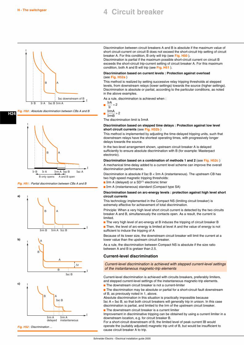
Schneider Electric - Electrical installation guide 2005
H - The switchgear
H24
Discrimination between circuit breakers A and B is absolute if the maximum value ofshort circuit-current on circuit B does not exceed the short-circuit trip setting of circuitbreaker A. For this condition, B only will trip (see Fig. H50 ).Discrimination is partial if the maximum possible short-circuit current on circuit Bexceeds the short-circuit trip-current setting of circuit breaker A. For this maximumcondition, both A and B will trip (see Fig. H51 ).
Discrimination based on current levels : Protection against overload(see Fig. H52a )This method is realized by setting successive relay tripping thresholds at steppedlevels, from downstream relays (lower settings) towards the source (higher settings).Discrimination is absolute or partial, according to the particular conditions, as notedin the above examples.
As a rule, discrimination is achieved when :
c IIrAr< 2
c IIrmArmB
> 2
The discrimination limit is IrmA
Discrimination based on stepped time delays : Protection against low levelshort circuit currents (see Fig. H52b )This method is implemented by adjusting the time-delayed tripping units, such thatdownstream relays have the shortest operating times, with progressively longerdelays towards the source.
In the two-level arrangement shown, upstream circuit breaker A is delayedsufficiently to ensure absolute discrimination with B (for example: Masterpactelectronic).
Discrimination based on a combination of methods 1 and 2 (see Fig. H52c )A mechanical time-delay added to a current level scheme can improve the overalldiscrimination performance.
Discrimination is absolute if Isc B < Irm A (instantaneous). The upstream CB hastwo high-speed magnetic tripping thresholds:c Irm A (delayed) or a SD(1) electronic timerc Irm A (instantaneous) standard (Compact type SA)
Discrimination based on arc-energy levels : protection against high level shortcircuit currentsThis technology implemented in the Compact NS (limiting circuit breaker) isextremely effective for achievement of total discrimination.
Principle: When a very high level short circuit current is detected by the two circuitsbreaker A and B, simultaneously the contacts open. As a result, the current islimited.c The very high level of arc-energy at B induces the tripping of circuit breaker Bc Then, the level of arc-energy is limited at level A and the value of energy is notsufficient to induce the tripping of A
Because of its lower size, the downstream circuit breaker will limit the current at alower value than the upstream circuit breaker.
As a rule, the discrimination between Compact NS is absolute if the size ratiobetween A and B is gretaer than 2.5.
Current-level discrimination
t
Irm A Isc BIr AIr B
B A
Isc AI
A and B openB only opens
Fig. H51 : Partial discrimination between CBs A and B
t
Irm AIr AIr B
B A
Isc B
Isc downstream of BI
Fig. H50 : Absolute discrimination between CBs A and B
Current-level discrimination is achieved with stepped current-level settingsof the instantaneous magnetic-trip elements
I
t
Irm AIrm B Icc B
B A
a)
b)
I
t
Isc B
∆t
A
B
A
B
c) t
Irm Adelayed
Isc B
I
B A
Irm Ainstantaneous
Fig. H52 : Discrimination ...
Current-level discrimination is achieved with circuits breakers, preferably limiters,and stepped current-level settings of the instantaneous magnetic-trip elements.c The downstream circuit breaker is not a current-limiterc The discrimination may be absolute or partial for a short-circuit fault downstreamof B, as previously noted in 1, above.Absolute discrimination in this situation is practically impossible becauseIsc A ≈ Isc B, so that both circuit breakers will generally trip in unison. In this casediscrimination is partial, and limited to the Irm of the upstream circuit breaker.c The downstream circuit breaker is a current limiterImprovement in discriminative tripping can be obtained by using a current limiter in adownstream location, e.g. for circuit breaker B.For a short-circuit downstream of B, the limited level of peak current IB wouldoperate the (suitably adjusted) magnetic trip unit of B, but would be insufficient tocause circuit breaker A to trip.
4 Circuit breaker
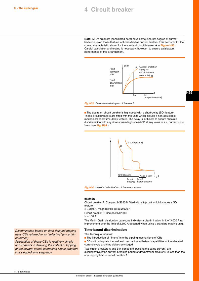
Schneider Electric - Electrical installation guide 2005
H - The switchgear
H25
4 Circuit breaker
Note: All LV breakers (considered here) have some inherent degree of currentlimitation, even those that are not classified as current limiters. This accounts for thecurved characteristic shown for the standard circuit breaker A in Figure H53 .Careful calculation and testing is necessary, however, to ensure satisfactoryperformance of this arrangement.
(1) Short-delay
I
I peak
Iscprospective (rms)
Current limitation curve for circuit breaker (see note)
Isc
A
B
Fault upstream of B
Fault downstream of B
Fig. H53 : Downstream limiting circuit breaker B
Fig. H54 : Use of a “selective” circuit breaker upstream
I
t
Irm Adelayed
A (Compact S)
Irm Sinstantaneous
B
Only B opens A and B open
c The upstream circuit breaker is highspeed with a short-delay (SD) feature.These circuit breakers are fitted with trip units which include a non-adjustablemechanical short-time-delay feature. The delay is sufficient to ensure absolutediscrimination with any downstream high-speed CB at any value of s.c. current up toIrms (see Fig. H54 ).
ExampleCircuit breaker A: Compact NS250 N fitted with a trip unit which includes a SDfeature.Ir = 250 A, magnetic trip set at 2,000 A
Circuit breaker B: Compact NS100NIr = 100 A
The Merlin Gerin distribution catalogue indicates a discrimination limit of 3,000 A (animprovement over the limit of 2,500 A obtained when using a standard tripping unit).
Time-based discriminationThis technique requires:c The introduction of “timers” into the tripping mechanisms of CBsc CBs with adequate thermal and mechanical withstand capabilities at the elevatedcurrent levels and time delays envisaged
Two circuit breakers A and B in series (i.e. passing the same current) arediscriminative if the current-breaking period of downstream breaker B is less than thenon-tripping time of circuit breaker A.
Discrimination based on time-delayed trippinguses CBs referred to as “selective” (in certaincountries).Application of these CBs is relatively simpleand consists in delaying the instant of trippingof the several series-connected circuit breakersin a stepped time sequence
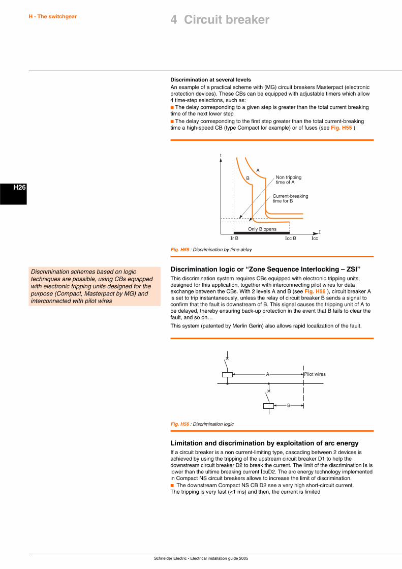
Schneider Electric - Electrical installation guide 2005
H - The switchgear
H26
Discrimination at several levelsAn example of a practical scheme with (MG) circuit breakers Masterpact (electronicprotection devices). These CBs can be equipped with adjustable timers which allow4 time-step selections, such as:c The delay corresponding to a given step is greater than the total current breakingtime of the next lower stepc The delay corresponding to the first step greater than the total current-breakingtime a high-speed CB (type Compact for example) or of fuses (see Fig. H55 )
Discrimination schemes based on logictechniques are possible, using CBs equippedwith electronic tripping units designed for thepurpose (Compact, Masterpact by MG) andinterconnected with pilot wires
I
t
Icc B
A
Icc
B
Only B opens
Current-breaking time for B
Non tripping time of A
Ir B
Fig. H55 : Discrimination by time delay
A Pilot wires
B
Fig. H56 : Discrimination logic
Discrimination logic or “Zone Sequence Interlocking – ZSI”This discrimination system requires CBs equipped with electronic tripping units,designed for this application, together with interconnecting pilot wires for dataexchange between the CBs. With 2 levels A and B (see Fig. H56 ), circuit breaker Ais set to trip instantaneously, unless the relay of circuit breaker B sends a signal toconfirm that the fault is downstream of B. This signal causes the tripping unit of A tobe delayed, thereby ensuring back-up protection in the event that B fails to clear thefault, and so on…
This system (patented by Merlin Gerin) also allows rapid localization of the fault.
Limitation and discrimination by exploitation of arc energyIf a circuit breaker is a non current-limiting type, cascading between 2 devices isachieved by using the tripping of the upstream circuit breaker D1 to help thedownstream circuit breaker D2 to break the current. The limit of the discrimination Is islower than the ultime breaking current IcuD2. The arc energy technology implementedin Compact NS circuit breakers allows to increase the limit of discrimination.c The downstream Compact NS CB D2 see a very high short-circuit current.The tripping is very fast (<1 ms) and then, the current is limited
4 Circuit breaker
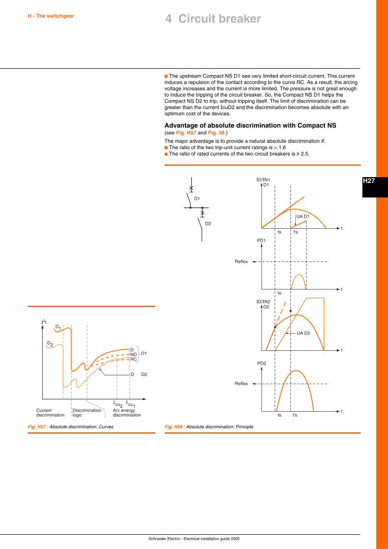
Schneider Electric - Electrical installation guide 2005
H - The switchgear
H27
4 Circuit breaker
Fig. H58 : Absolute discrimination: Principle
I I
D1
D1DNDRC
D2
I2t
D2D
cu2 cu1Currentdiscrimination
Discriminationlogic
Arc energydiscrimination
Fig. H57 : Absolute discrimination: Curves
UA D2
UA D1
D1
D1
D2
D2ID/IN2
PD2
ID/IN1
t
t
t
t
ts t's
PD1
ts
ts t's
Reflex
Reflex
c The upstream Compact NS D1 see very limited short-circuit current. This currentinduces a repulsion of the contact according to the curve RC. As a result, the arcingvoltage increases and the current is more limited. The pressure is not great enoughto induce the tripping of the circuit breaker. So, the Compact NS D1 helps theCompact NS D2 to trip, without tripping itself. The limit of discrimination can begreater than the current IcuD2 and the discrimination becomes absolute with anoptimum cost of the devices.
Advantage of absolute discrimination with Compact NS(see Fig. H57 and Fig. 58 )
The major advantage is to provide a natural absolute discrimination if:c The ratio of the two trip-unit current ratings is > 1.6c The ratio of rated currents of the two circuit breakers is u 2.5.
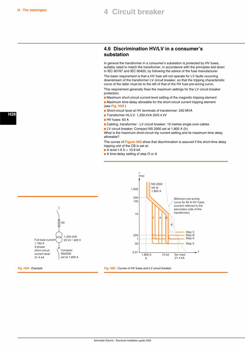
Schneider Electric - Electrical installation guide 2005
H - The switchgear
H28
4 Circuit breaker
Fig. H59 : Example
63
1,250 kVA20 kV / 400 V
Compact NS2000 set at 1,800 A
Full-load current1,760 A 3-phase short-circuit current level31.4 kA
I
t(ms)
Step CStep BStep A
Step 050
1220
10
100200
1,000
NS 2000set at 1,800 A
1,800 AIr
Isc maxi31.4 kA
10 kA0.01
Minimum pre-arcing curve for 63 A HV fuses (current referred to the secondary side of the transformer)
1 4 6
8
Fig. H60 : Curves of HV fuses and LV circuit breaker
4.6 Discrimination HV/LV in a consumer’ssubstation
In general the transformer in a consumer’s substation is protected by HV fuses,suitably rated to match the transformer, in accordance with the principles laid downin IEC 60787 and IEC 60420, by following the advice of the fuse manufacturer.
The basic requirement is that a HV fuse will not operate for LV faults occurringdownstream of the transformer LV circuit breaker, so that the tripping characteristiccurve of the latter must be to the left of that of the HV fuse pre-arcing curve.
This requirement generally fixes the maximum settings for the LV circuit breakerprotection:c Maximum short-circuit current-level setting of the magnetic tripping elementc Maximum time-delay allowable for the short-circuit current tripping element(see Fig. H59 )c Short-circuit level at HV terminals of transformer: 250 MVAc Transformer HL/LV: 1,250 kVA 20/0.4 kVc HV fuses: 63 Ac Cabling, transformer - LV circuit breaker: 10 metres single-core cablesc LV circuit breaker: Compact NS 2000 set at 1,800 A (Ir)What is the maximum short-circuit trip current setting and its maximum time delayallowable?
The curves of Figure H60 show that discrimination is assured if the short-time delaytripping unit of the CB is set at:c A level i 6 Ir = 10.8 kAc A time-delay setting of step O or A
Schneider Electric - Electrical installation guide 2005
J1
Chapter JProtection against voltage surges
Contents
General J2
1.1 What is a voltage surge? J2
1.2 The four voltage surge types J2
1.3 Main characteristics of voltage surges J4
1.4 Different propagation modes J5
Overvoltage protection devices J6
2.1 Primary protection devices (protection of installations J6against lightning: IEPF)
2.2 Secondary protection devices (porotection of internal J8installations against lightning : IIPF)
Standards J11
3.1 Surge arrester description J11
3.2 Product standards J11
3.3 Surge arrester data according to the IEC 61643-11 standard J11
3.4 Surge arrester installation standards J13
Choosing a protection device J14
4.1 Assessing the overvoltage risk for the installation J14to be protected
4.2 Choosing surge arrester flow capacity (LV network) J16
4.3 Choosing surge arrester in function of earthing system J16
4.4 Choosing a disconnection circuit breaker J17
1
2
3
4
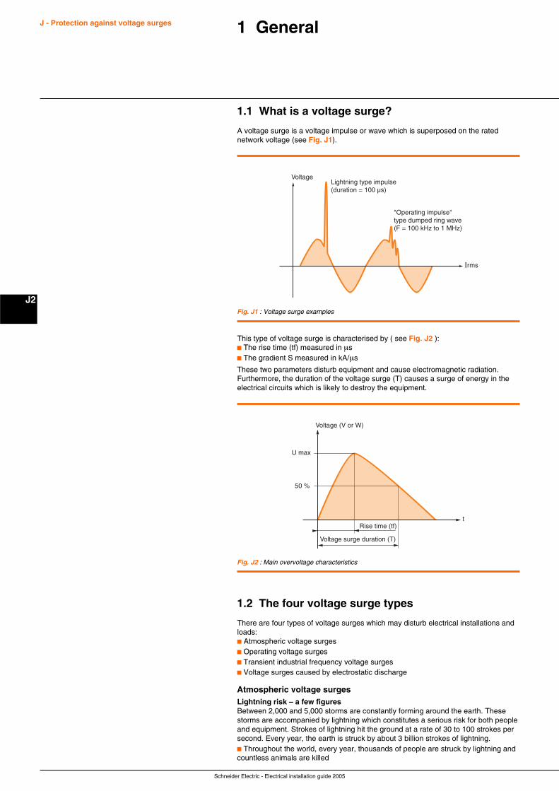
Schneider Electric - Electrical installation guide 2005
J - Protection against voltage surges
J2
1 General
1.1 What is a voltage surge?
A voltage surge is a voltage impulse or wave which is superposed on the ratednetwork voltage (see Fig. J1).
VoltageLightning type impulse(duration = 100 µs)
"Operating impulse"type dumped ring wave(F = 100 kHz to 1 MHz)
Irms
Fig. J1 : Voltage surge examples
This type of voltage surge is characterised by ( see Fig. J2 ):c The rise time (tf) measured in µsc The gradient S measured in kA/µs
These two parameters disturb equipment and cause electromagnetic radiation.Furthermore, the duration of the voltage surge (T) causes a surge of energy in theelectrical circuits which is likely to destroy the equipment.
Voltage (V or W)
U max
50 %
tRise time (tf)
Voltage surge duration (T)
Fig. J2 : Main overvoltage characteristics
1.2 The four voltage surge types
There are four types of voltage surges which may disturb electrical installations andloads:c Atmospheric voltage surgesc Operating voltage surgesc Transient industrial frequency voltage surgesc Voltage surges caused by electrostatic discharge
Atmospheric voltage surgesLightning risk – a few figuresBetween 2,000 and 5,000 storms are constantly forming around the earth. Thesestorms are accompanied by lightning which constitutes a serious risk for both peopleand equipment. Strokes of lightning hit the ground at a rate of 30 to 100 strokes persecond. Every year, the earth is struck by about 3 billion strokes of lightning.c Throughout the world, every year, thousands of people are struck by lightning andcountless animals are killed
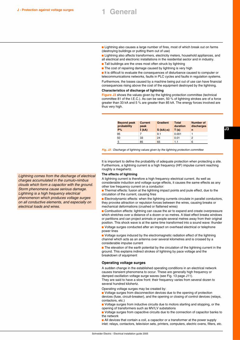
Schneider Electric - Electrical installation guide 2005
J3
J - Protection against voltage surges 1 General
Fig. J3 : Discharge of lightning values given by the lightning protection committee
Lightning comes from the discharge of electricalcharges accumulated in the cumulo-nimbusclouds which form a capacitor with the ground.Storm phenomena cause serious damage.Lightning is a high frequency electricalphenomenon which produces voltage surgeson all conductive elements, and especially onelectrical loads and wires.
Beyond peak Current Gradient Total Number ofprobability peak duration dischargesP% I (kA) S (kA/µs) T (s) n95 7 9.1 0.001 150 33 24 0.01 25 85 65 1.1 6
c Lightning also causes a large number of fires, most of which break out on farms(destroying buildings or putting them out of use)c Lightning also affects transformers, electricity meters, household appliances, andall electrical and electronic installations in the residential sector and in industry.c Tall buildings are the ones most often struck by lightningc The cost of repairing damage caused by lightning is very highc It is difficult to evaluate the consequences of disturbance caused to computer ortelecommunications networks, faults in PLC cycles and faults in regulation systems.
Furthermore, the losses caused by a machine being put out of use can have financialconsequences rising above the cost of the equipment destroyed by the lightning.
Characteristics of discharge of lightningFigure J3 shows the values given by the lighting protection committee (technicalcommittee 81 of the I.E.C.). As can be seen, 50 % of lightning strokes are of a forcegreater than 33 kA and 5 % are greater than 85 kA. The energy forces involved arethus very high.
It is important to define the probability of adequate protection when protecting a site.Furthermore, a lightning current is a high frequency (HF) impulse current reachingroughly a megahertz.
The effects of lightningA lightning current is therefore a high frequency electrical current. As well asconsiderable induction and voltage surge effects, it causes the same effects as anyother low frequency current on a conductor:c Thermal effects: fusion at the lightning impact points and joule effect, due to thecirculation of the current, causing firesc Electrodynamic effects: when the lightning currents circulate in parallel conductors,they provoke attraction or repulsion forces between the wires, causing breaks ormechanical deformations (crushed or flattened wires)c Combustion effects: lightning can cause the air to expand and create overpressurewhich stretches over a distance of a dozen or so metres. A blast effect breaks windowsor partitions and can project animals or people several metres away from their originalposition. This shock wave is at the same time transformed into a sound wave: thunderc Voltage surges conducted after an impact on overhead electrical or telephonepower linesc Voltage surges induced by the electromagnetic radiation effect of the lightningchannel which acts as an antenna over several kilometres and is crossed by aconsiderable impulse currentc The elevation of the earth potential by the circulation of the lightning current in theground. This explains indirect strokes of lightning by pace voltage and thebreakdown of equipment
Operating voltage surgesA sudden change in the established operating conditions in an electrical networkcauses transient phenomena to occur. These are generally high frequency ordamped oscillation voltage surge waves (see Fig. 13 page J11).They are said to have a slow front: their frequency varies from several dozen toseveral hundred kilohertz.
Operating voltage surges may be created by:c Voltage surges from disconnection devices due to the opening of protectiondevices (fuse, circuit-breaker), and the opening or closing of control devices (relays,contactors, etc.)c Voltage surges from inductive circuits due to motors starting and stopping, or theopening of transformers such as MV/LV substationsc Voltage surges from capacitive circuits due to the connection of capacitor banks tothe networkc All devices that contain a coil, a capacitor or a transformer at the power supplyinlet: relays, contactors, television sets, printers, computers, electric ovens, filters, etc.
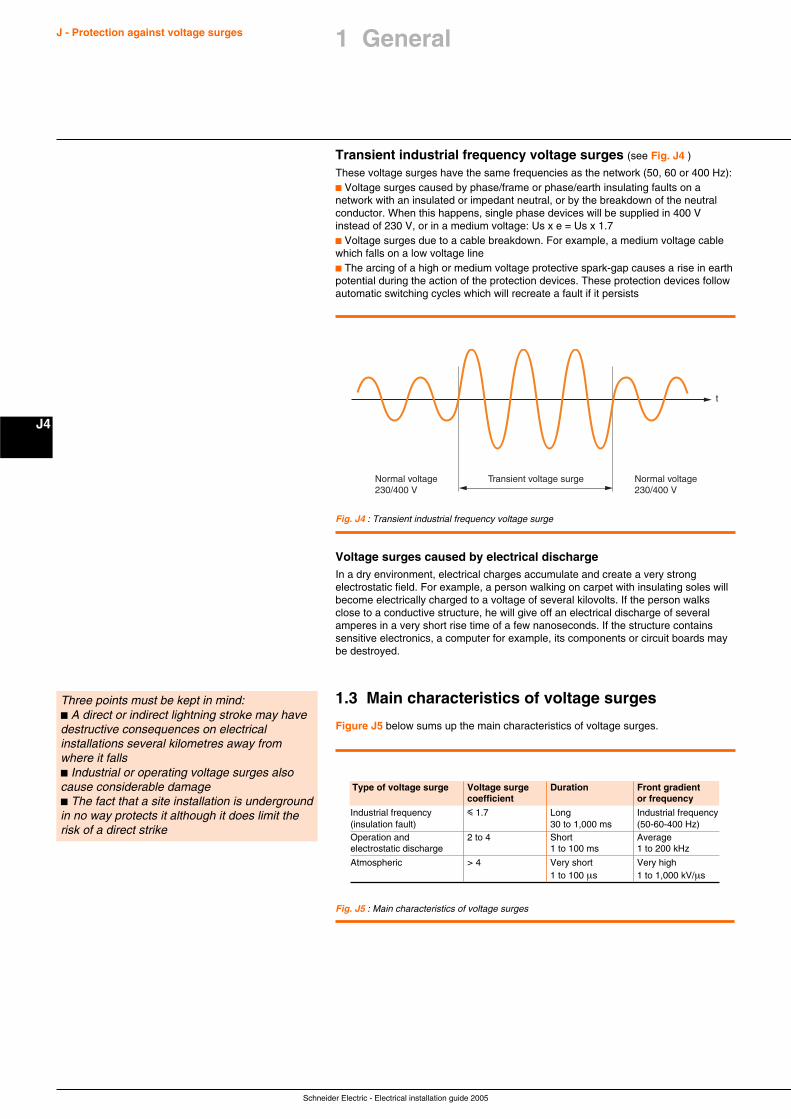
Schneider Electric - Electrical installation guide 2005
J - Protection against voltage surges
J4
Transient industrial frequency voltage surges (see Fig. J4 )
These voltage surges have the same frequencies as the network (50, 60 or 400 Hz):c Voltage surges caused by phase/frame or phase/earth insulating faults on anetwork with an insulated or impedant neutral, or by the breakdown of the neutralconductor. When this happens, single phase devices will be supplied in 400 Vinstead of 230 V, or in a medium voltage: Us x e = Us x 1.7c Voltage surges due to a cable breakdown. For example, a medium voltage cablewhich falls on a low voltage linec The arcing of a high or medium voltage protective spark-gap causes a rise in earthpotential during the action of the protection devices. These protection devices followautomatic switching cycles which will recreate a fault if it persists
Voltage surges caused by electrical dischargeIn a dry environment, electrical charges accumulate and create a very strongelectrostatic field. For example, a person walking on carpet with insulating soles willbecome electrically charged to a voltage of several kilovolts. If the person walksclose to a conductive structure, he will give off an electrical discharge of severalamperes in a very short rise time of a few nanoseconds. If the structure containssensitive electronics, a computer for example, its components or circuit boards maybe destroyed.
1.3 Main characteristics of voltage surges
Figure J5 below sums up the main characteristics of voltage surges.
Fig. J4 : Transient industrial frequency voltage surge
Normal voltage230/400 V
Normal voltage230/400 V
t
Transient voltage surge
Three points must be kept in mind:c A direct or indirect lightning stroke may havedestructive consequences on electricalinstallations several kilometres away fromwhere it fallsc Industrial or operating voltage surges alsocause considerable damagec The fact that a site installation is undergroundin no way protects it although it does limit therisk of a direct strike
Type of voltage surge Voltage surge Duration Front gradientcoefficient or frequency
Industrial frequency i 1.7 Long Industrial frequency(insulation fault) 30 to 1,000 ms (50-60-400 Hz)Operation and 2 to 4 Short Averageelectrostatic discharge 1 to 100 ms 1 to 200 kHz
Atmospheric > 4 Very short Very high1 to 100 µs 1 to 1,000 kV/µs
Fig. J5 : Main characteristics of voltage surges
1 General
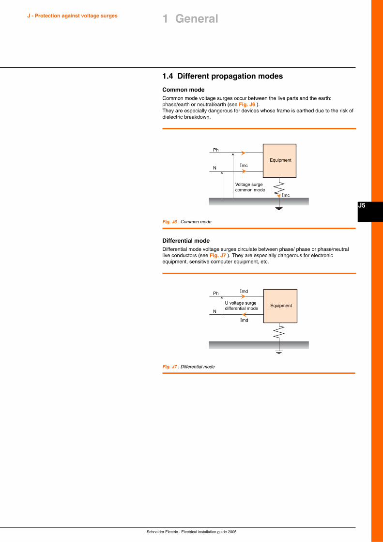
Schneider Electric - Electrical installation guide 2005
J5
J - Protection against voltage surges 1 General
1.4 Different propagation modes
Common modeCommon mode voltage surges occur between the live parts and the earth:phase/earth or neutral/earth (see Fig. J6 ).They are especially dangerous for devices whose frame is earthed due to the risk ofdielectric breakdown.
Fig. J6 : Common mode
Fig. J7 : Differential mode
Ph Imd
N
Imd
U voltage surgedifferential mode
Equipment
Ph
Imc
Imc
N
Voltage surgecommon mode
Equipment
Differential modeDifferential mode voltage surges circulate between phase/ phase or phase/neutrallive conductors (see Fig. J7 ). They are especially dangerous for electronicequipment, sensitive computer equipment, etc.
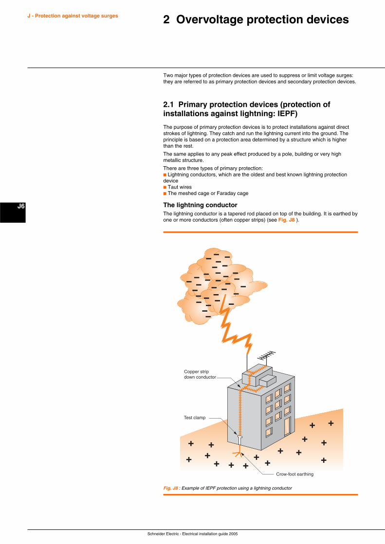
Schneider Electric - Electrical installation guide 2005
J - Protection against voltage surges
J6
2 Overvoltage protection devices
Two major types of protection devices are used to suppress or limit voltage surges:they are referred to as primary protection devices and secondary protection devices.
2.1 Primary protection devices (protection ofinstallations against lightning: IEPF)
The purpose of primary protection devices is to protect installations against directstrokes of lightning. They catch and run the lightning current into the ground. Theprinciple is based on a protection area determined by a structure which is higherthan the rest.
The same applies to any peak effect produced by a pole, building or very highmetallic structure.
There are three types of primary protection:c Lightning conductors, which are the oldest and best known lightning protectiondevicec Taut wiresc The meshed cage or Faraday cage
The lightning conductorThe lightning conductor is a tapered rod placed on top of the building. It is earthed byone or more conductors (often copper strips) (see Fig. J8 ).
Fig. J8 : Example of IEPF protection using a lightning conductor
Copper stripdown conductor
Test clamp
Crow-foot earthing
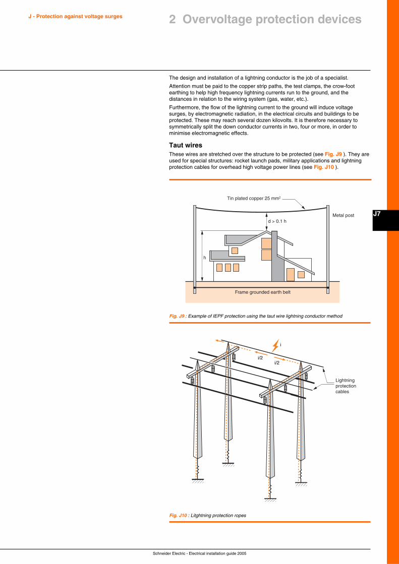
Schneider Electric - Electrical installation guide 2005
J7
J - Protection against voltage surges
The design and installation of a lightning conductor is the job of a specialist.
Attention must be paid to the copper strip paths, the test clamps, the crow-footearthing to help high frequency lightning currents run to the ground, and thedistances in relation to the wiring system (gas, water, etc.).
Furthermore, the flow of the lightning current to the ground will induce voltagesurges, by electromagnetic radiation, in the electrical circuits and buildings to beprotected. These may reach several dozen kilovolts. It is therefore necessary tosymmetrically split the down conductor currents in two, four or more, in order tominimise electromagnetic effects.
Taut wiresThese wires are stretched over the structure to be protected (see Fig. J9 ). They areused for special structures: rocket launch pads, military applications and lightningprotection cables for overhead high voltage power lines (see Fig. J10 ).
Fig. J9 : Example of IEPF protection using the taut wire lightning conductor method
Fig. J10 : Litghtning protection ropes
Tin plated copper 25 mm2
Frame grounded earth belt
h
d > 0.1 hMetal post
i/2i/2
i
Lightning protection cables
2 Overvoltage protection devices
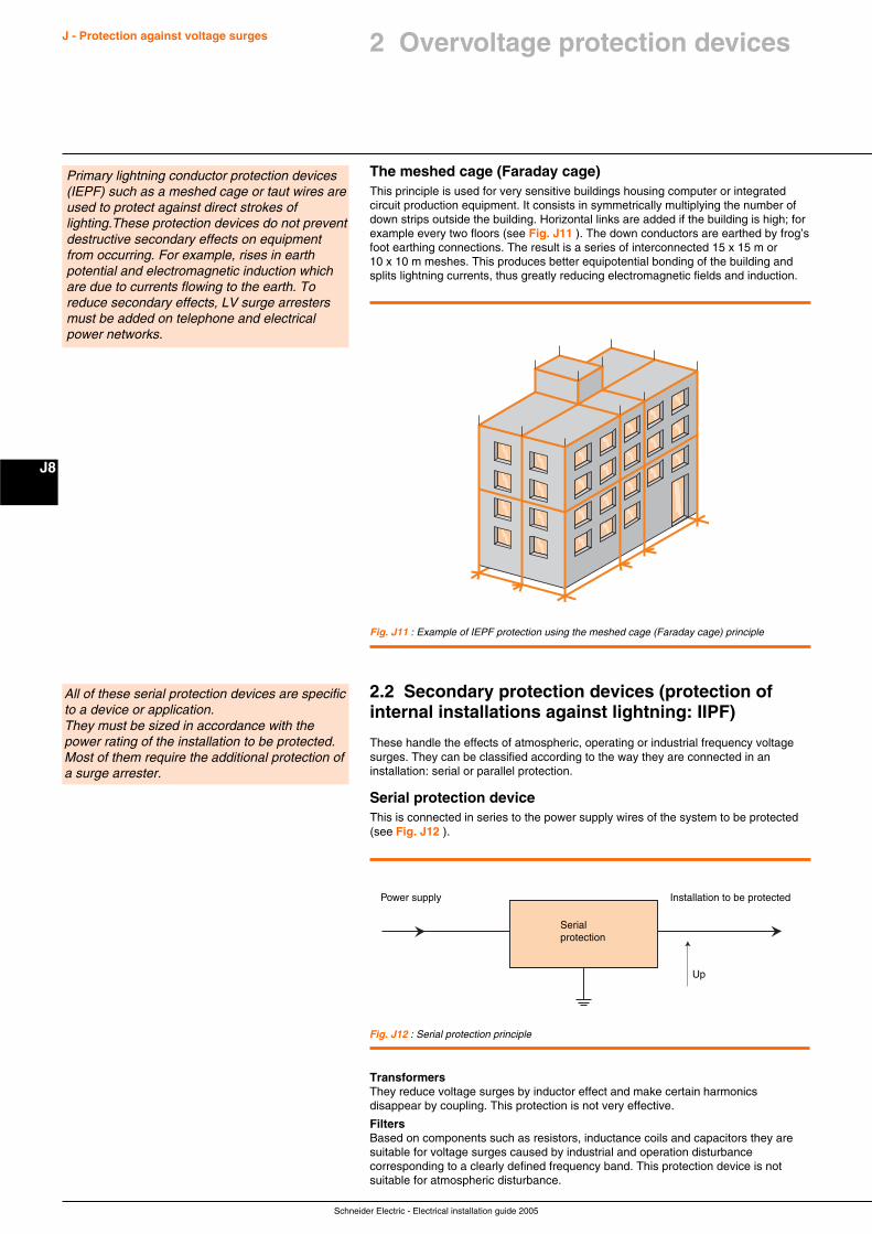
Schneider Electric - Electrical installation guide 2005
J - Protection against voltage surges
J8
The meshed cage (Faraday cage)This principle is used for very sensitive buildings housing computer or integratedcircuit production equipment. It consists in symmetrically multiplying the number ofdown strips outside the building. Horizontal links are added if the building is high; forexample every two floors (see Fig. J11 ). The down conductors are earthed by frog’sfoot earthing connections. The result is a series of interconnected 15 x 15 m or10 x 10 m meshes. This produces better equipotential bonding of the building andsplits lightning currents, thus greatly reducing electromagnetic fields and induction.
Primary lightning conductor protection devices(IEPF) such as a meshed cage or taut wires areused to protect against direct strokes oflighting.These protection devices do not preventdestructive secondary effects on equipmentfrom occurring. For example, rises in earthpotential and electromagnetic induction whichare due to currents flowing to the earth. Toreduce secondary effects, LV surge arrestersmust be added on telephone and electricalpower networks.
Fig. J11 : Example of IEPF protection using the meshed cage (Faraday cage) principle
2.2 Secondary protection devices (protection ofinternal installations against lightning: IIPF)
These handle the effects of atmospheric, operating or industrial frequency voltagesurges. They can be classified according to the way they are connected in aninstallation: serial or parallel protection.
Serial protection deviceThis is connected in series to the power supply wires of the system to be protected(see Fig. J12 ).
All of these serial protection devices are specificto a device or application.They must be sized in accordance with thepower rating of the installation to be protected.Most of them require the additional protection ofa surge arrester.
Installation to be protectedPower supply
Up
Serialprotection
Fig. J12 : Serial protection principle
TransformersThey reduce voltage surges by inductor effect and make certain harmonicsdisappear by coupling. This protection is not very effective.
FiltersBased on components such as resistors, inductance coils and capacitors they aresuitable for voltage surges caused by industrial and operation disturbancecorresponding to a clearly defined frequency band. This protection device is notsuitable for atmospheric disturbance.
2 Overvoltage protection devices
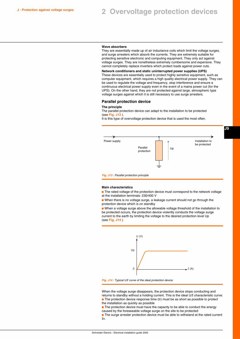
Schneider Electric - Electrical installation guide 2005
J9
J - Protection against voltage surges
Wave absorbersThey are essentially made up of air inductance coils which limit the voltage surges,and surge arresters which absorb the currents. They are extremely suitable forprotecting sensitive electronic and computing equipment. They only act againstvoltage surges. They are nonetheless extremely cumbersome and expensive. Theycannot completely replace inverters which protect loads against power cuts.
Network conditioners and static uninterrupted power supplies (UPS)These devices are essentially used to protect highly sensitive equipment, such ascomputer equipment, which requires a high quality electrical power supply. They canbe used to regulate the voltage and frequency, stop interference and ensure acontinuous electrical power supply even in the event of a mains power cut (for theUPS). On the other hand, they are not protected against large, atmospheric typevoltage surges against which it is still necessary to use surge arresters.
Parallel protection deviceThe principleThe parallel protection device can adapt to the installation to be protected(see Fig. J13 ).It is this type of overvoltage protection device that is used the most often.
Main characteristicsc The rated voltage of the protection device must correspond to the network voltageat the installation terminals: 230/400 Vc When there is no voltage surge, a leakage current should not go through theprotection device which is on standbyc When a voltage surge above the allowable voltage threshold of the installation tobe protected occurs, the protection device violently conducts the voltage surgecurrent to the earth by limiting the voltage to the desired protection level Up(see Fig. J14 ).
2 Overvoltage protection devices
Installation to be protected
Power supply
UpParallelprotection
Fig. J13 : Parallel protection principle
Fig. J14 : Typical U/I curve of the ideal protection device
0 I (A)
U (V)
Up
When the voltage surge disappears, the protection device stops conducting andreturns to standby without a holding current. This is the ideal U/I characteristic curve:c The protection device response time (tr) must be as short as possible to protectthe installation as quickly as possiblec The protection device must have the capacity to be able to conduct the energycaused by the foreseeable voltage surge on the site to be protectedc The surge arrester protection device must be able to withstand at the rated currentIn.
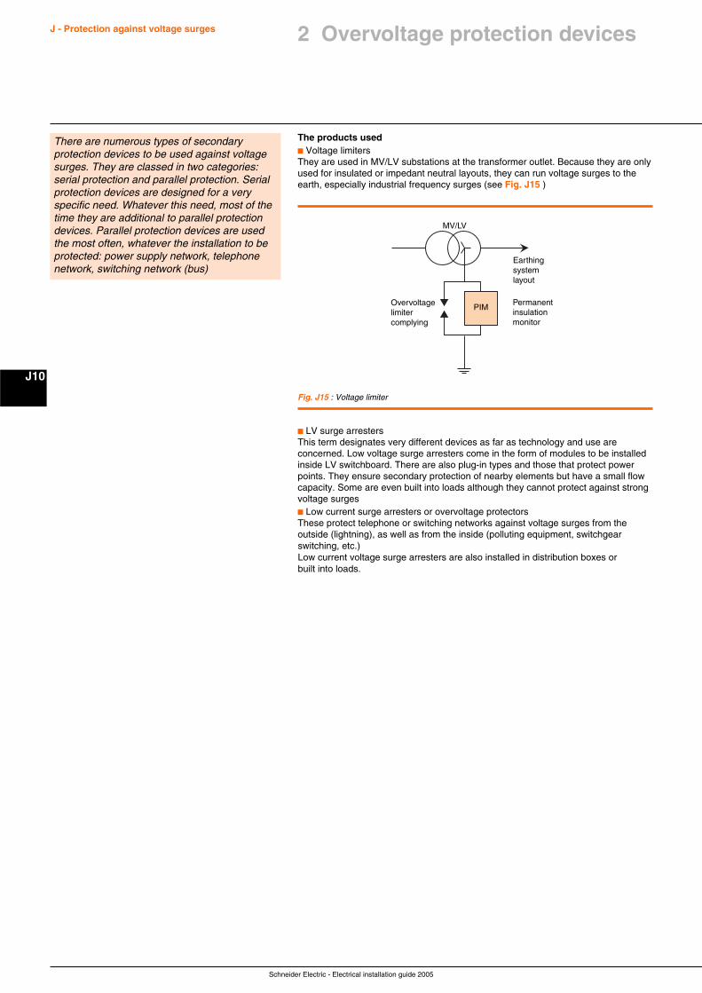
Schneider Electric - Electrical installation guide 2005
J - Protection against voltage surges
J10
The products usedc Voltage limitersThey are used in MV/LV substations at the transformer outlet. Because they are onlyused for insulated or impedant neutral layouts, they can run voltage surges to theearth, especially industrial frequency surges (see Fig. J15 )
There are numerous types of secondaryprotection devices to be used against voltagesurges. They are classed in two categories:serial protection and parallel protection. Serialprotection devices are designed for a veryspecific need. Whatever this need, most of thetime they are additional to parallel protectiondevices. Parallel protection devices are usedthe most often, whatever the installation to beprotected: power supply network, telephonenetwork, switching network (bus)
Fig. J15 : Voltage limiter
c LV surge arrestersThis term designates very different devices as far as technology and use areconcerned. Low voltage surge arresters come in the form of modules to be installedinside LV switchboard. There are also plug-in types and those that protect powerpoints. They ensure secondary protection of nearby elements but have a small flowcapacity. Some are even built into loads although they cannot protect against strongvoltage surgesc Low current surge arresters or overvoltage protectorsThese protect telephone or switching networks against voltage surges from theoutside (lightning), as well as from the inside (polluting equipment, switchgearswitching, etc.)Low current voltage surge arresters are also installed in distribution boxes orbuilt into loads.
Earthing system layout
MV/LV
Overvoltagelimitercomplying
Permanent insulationmonitor
PIM
2 Overvoltage protection devices
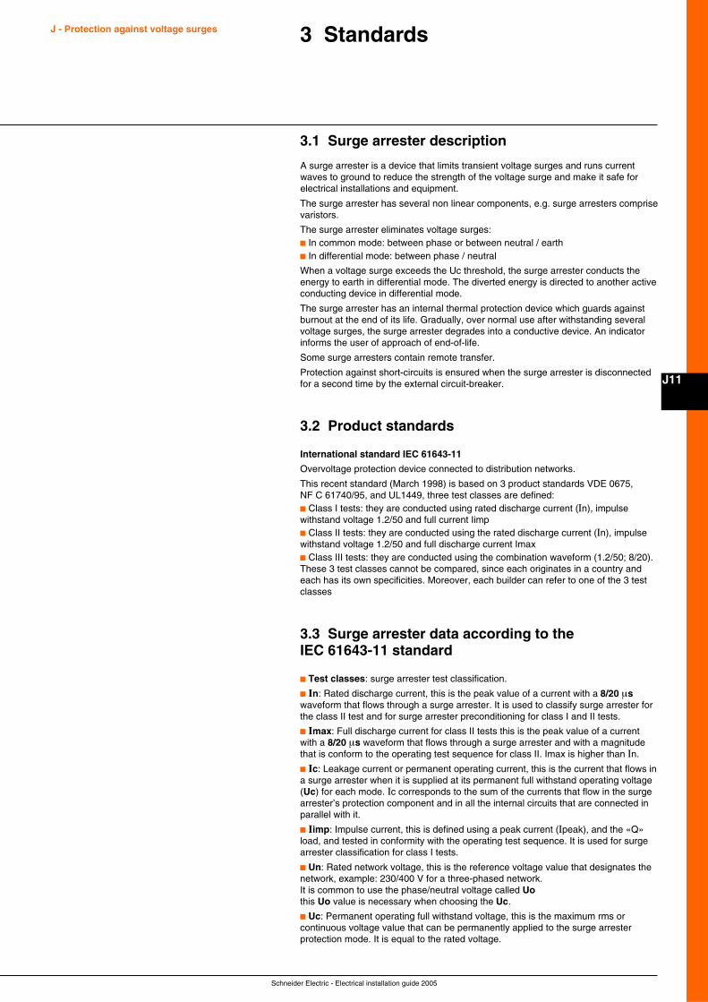
Schneider Electric - Electrical installation guide 2005
J11
3 Standards
3.1 Surge arrester description
A surge arrester is a device that limits transient voltage surges and runs currentwaves to ground to reduce the strength of the voltage surge and make it safe forelectrical installations and equipment.
The surge arrester has several non linear components, e.g. surge arresters comprisevaristors.
The surge arrester eliminates voltage surges:c In common mode: between phase or between neutral / earthc In differential mode: between phase / neutral
When a voltage surge exceeds the Uc threshold, the surge arrester conducts theenergy to earth in differential mode. The diverted energy is directed to another activeconducting device in differential mode.
The surge arrester has an internal thermal protection device which guards againstburnout at the end of its life. Gradually, over normal use after withstanding severalvoltage surges, the surge arrester degrades into a conductive device. An indicatorinforms the user of approach of end-of-life.
Some surge arresters contain remote transfer.
Protection against short-circuits is ensured when the surge arrester is disconnectedfor a second time by the external circuit-breaker.
3.2 Product standards
International standard IEC 61643-11
Overvoltage protection device connected to distribution networks.
This recent standard (March 1998) is based on 3 product standards VDE 0675,NF C 61740/95, and UL1449, three test classes are defined:c Class I tests: they are conducted using rated discharge current (In), impulsewithstand voltage 1.2/50 and full current Iimpc Class II tests: they are conducted using the rated discharge current (In), impulsewithstand voltage 1.2/50 and full discharge current Imaxc Class III tests: they are conducted using the combination waveform (1.2/50; 8/20).These 3 test classes cannot be compared, since each originates in a country andeach has its own specificities. Moreover, each builder can refer to one of the 3 testclasses
3.3 Surge arrester data according to theIEC 61643-11 standard
c Test classes: surge arrester test classification.
c In: Rated discharge current, this is the peak value of a current with a 8/20 µswaveform that flows through a surge arrester. It is used to classify surge arrester forthe class II test and for surge arrester preconditioning for class I and II tests.
c Imax: Full discharge current for class II tests this is the peak value of a currentwith a 8/20 µs waveform that flows through a surge arrester and with a magnitudethat is conform to the operating test sequence for class II. Imax is higher than In.
c Ic: Leakage current or permanent operating current, this is the current that flows ina surge arrester when it is supplied at its permanent full withstand operating voltage(Uc) for each mode. Ic corresponds to the sum of the currents that flow in the surgearrester’s protection component and in all the internal circuits that are connected inparallel with it.
c Iimp: Impulse current, this is defined using a peak current (Ipeak), and the «Q»load, and tested in conformity with the operating test sequence. It is used for surgearrester classification for class I tests.
c Un: Rated network voltage, this is the reference voltage value that designates thenetwork, example: 230/400 V for a three-phased network.It is common to use the phase/neutral voltage called Uothis Uo value is necessary when choosing the Uc.
c Uc: Permanent operating full withstand voltage, this is the maximum rms orcontinuous voltage value that can be permanently applied to the surge arresterprotection mode. It is equal to the rated voltage.
J - Protection against voltage surges
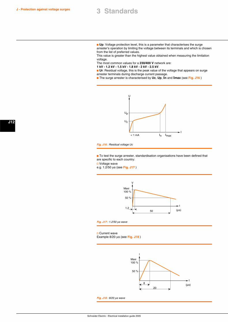
Schneider Electric - Electrical installation guide 2005
J - Protection against voltage surges
J12
c Up: Voltage protection level, this is a parameter that characterises the surgearrester’s operation by limiting the voltage between its terminals and which is chosenfrom the list of preferred values.This value is greater than the highest value obtained when measuring the limitationvoltage.The most common values for a 230/400 V network are:1 kV - 1.2 kV - 1.5 kV - 1.8 kV - 2 kV - 2.5 kV.c Ur: Residual voltage, this is the peak value of the voltage that appears on surgearrester terminals during discharge current passage.c The surge arrester is characterised by Uc, Up, In and Imax (see Fig. J16 )
In Imax< 1 mAI
U
Up
Uc
Fig. J16 : Residual voltage Uc
c To test the surge arrester, standardisation organisations have been defined thatare specific to each country:v Voltage wavee.g. 1.2/50 µs (see Fig. J17 )
Maxi100 %
50 %
1,250
t
(µs)
V
Fig. J17 : 1.2/50 µs wave
v Current waveExample 8/20 µs (see Fig. J18 )
20
8
Maxi100 %
I
50 %
t
(µs)
Fig. J18 : 8/20 µs wave
3 Standards
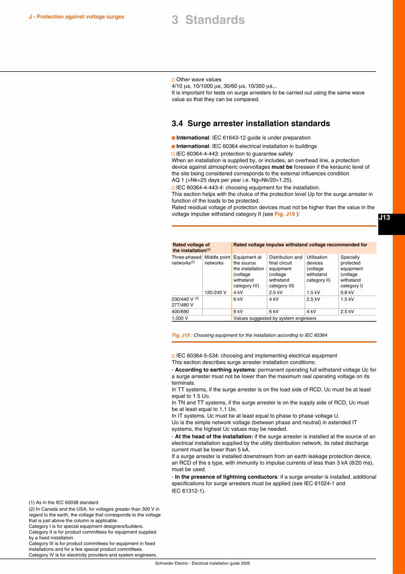
Schneider Electric - Electrical installation guide 2005
J13
J - Protection against voltage surges
v Other wave values4/10 µs, 10/1000 µs, 30/60 µs, 10/350 µs...It is important for tests on surge arresters to be carried out using the same wavevalue so that they can be compared.
3.4 Surge arrester installation standards
c International: IEC 61643-12 guide is under preparation
c International: IEC 60364 electrical installation in buildingsv IEC 60364-4-443: protection to guarantee safetyWhen an installation is supplied by, or includes, an overhead line, a protectiondevice against atmospheric overvoltages must be foreseen if the keraunic level ofthe site being considered corresponds to the external influences conditionAQ 1 (>Nk=25 days per year i.e. Ng=Nk/20=1.25).v IEC 60364-4-443-4: choosing equipment for the installation.This section helps with the choice of the protection level Up for the surge arrester infunction of the loads to be protected.Rated residual voltage of protection devices must not be higher than the value in thevoltage impulse withstand category II (see Fig. J19 ):
v IEC 60364-5-534: choosing and implementing electrical equipmentThis section describes surge arrester installation conditions:- According to earthing systems: permanent operating full withstand voltage Uc fora surge arrester must not be lower than the maximum real operating voltage on itsterminals.In TT systems, if the surge arrester is on the load side of RCD, Uc must be at leastequal to 1.5 Uo.In TN and TT systems, if the surge arrester is on the supply side of RCD, Uc mustbe at least equal to 1.1 Uo.In IT systems, Uc must be at least equal to phase to phase voltage U.Uo is the simple network voltage (between phase and neutral) in extended ITsystems, the highest Uc values may be needed.- At the head of the installation: if the surge arrester is installed at the source of anelectrical installation supplied by the utility distribution network, its rated dischargecurrent must be lower than 5 kA.If a surge arrester is installed downstream from an earth leakage protection device,an RCD of the s type, with immunity to impulse currents of less than 3 kA (8/20 ms),must be used.- In the presence of lightning conductors: if a surge arrester is installed, additionalspecifications for surge arresters must be applied (see IEC 61024-1 andIEC 61312-1).
Rated voltage of Rated voltage impulse withstand voltage recommended forthe installation(1)
Three-phased Middle point Equipment at Distribution and Utilisation Speciallynetworks(2) networks the source final circuit devices protected
the installation equipment (voltage equipment(voltage (voltage withstand (voltagewithstand withstand category II) withstandcategory IV) category III) category I)
120-240 V 4 kV 2.5 kV 1.5 kV 0.8 kV230/440 V (2) 6 kV 4 kV 2.5 kV 1.5 kV277/480 V400/690 8 kV 6 kV 4 kV 2.5 kV1,000 V Values suggested by system engineers
(1) As in the IEC 60038 standard(2) In Canada and the USA, for voltages greater than 300 V inregard to the earth, the voltage that corresponds to the voltagethat is just above the column is applicable.Category I is for special equipment designers/builders.Category II is for product committees for equipment suppliedby a fixed installation.Category III is for product committees for equipment in fixedinstallations and for a few special product committees.Category IV is for electricity providers and system engineers.
Fig. J19 : Choosing equipment for the installation according to IEC 60364
3 Standards
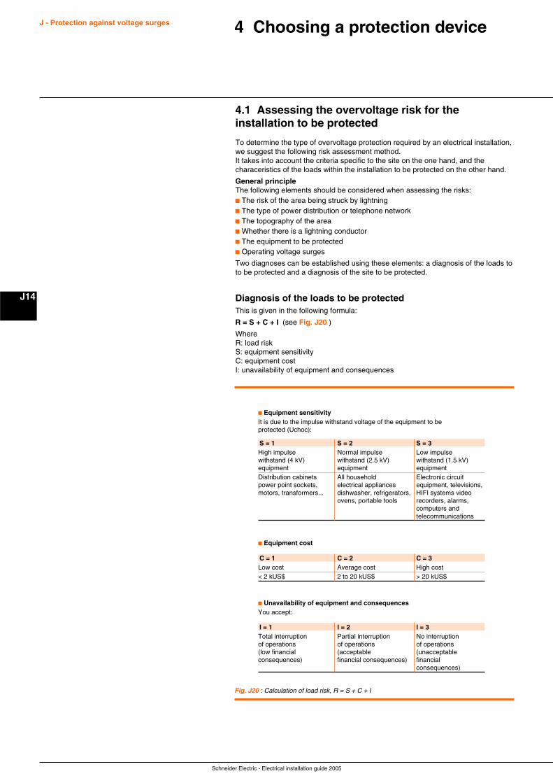
Schneider Electric - Electrical installation guide 2005
J - Protection against voltage surges
J14
4 Choosing a protection device
4.1 Assessing the overvoltage risk for theinstallation to be protected
To determine the type of overvoltage protection required by an electrical installation,we suggest the following risk assessment method.It takes into account the criteria specific to the site on the one hand, and thecharaceristics of the loads within the installation to be protected on the other hand.
General principleThe following elements should be considered when assessing the risks:c The risk of the area being struck by lightningc The type of power distribution or telephone networkc The topography of the areac Whether there is a lightning conductorc The equipment to be protectedc Operating voltage surges
Two diagnoses can be established using these elements: a diagnosis of the loads toto be protected and a diagnosis of the site to be protected.
Diagnosis of the loads to be protectedThis is given in the following formula:
R = S + C + I (see Fig. J20 )
WhereR: load riskS: equipment sensitivityC: equipment costI: unavailability of equipment and consequences
c Equipment sensitivityIt is due to the impulse withstand voltage of the equipment to beprotected (Uchoc):
S = 1 S = 2 S = 3High impulse Normal impulse Low impulsewithstand (4 kV) withstand (2.5 kV) withstand (1.5 kV)equipment equipment equipmentDistribution cabinets All household Electronic circuitpower point sockets, electrical appliances equipment, televisions,motors, transformers... dishwasher, refrigerators, HIFI systems video
ovens, portable tools recorders, alarms,computers andtelecommunications
C = 1 C = 2 C = 3Low cost Average cost High cost< 2 kUS$ 2 to 20 kUS$ > 20 kUS$
c Equipment cost
I = 1 I = 2 I = 3Total interruption Partial interruption No interruptionof operations of operations of operations(low financial (acceptable (unacceptableconsequences) financial consequences) financial
consequences)
c Unavailability of equipment and consequencesYou accept:
Fig. J20 : Calculation of load risk, R = S + C + I
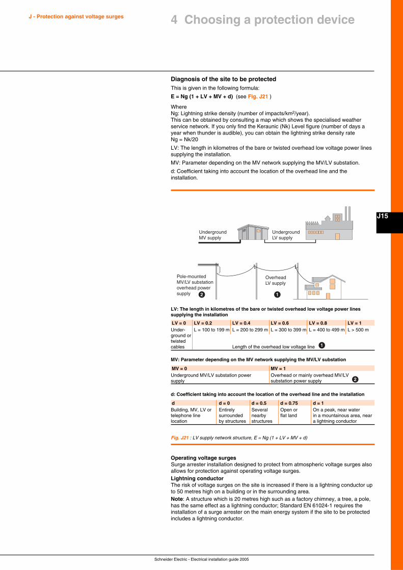
Schneider Electric - Electrical installation guide 2005
J15
J - Protection against voltage surges
Diagnosis of the site to be protectedThis is given in the following formula:
E = Ng (1 + LV + MV + d) (see Fig. J21 )
WhereNg: Lightning strike density (number of impacts/km2/year).This can be obtained by consulting a map which shows the specialised weatherservice network. If you only find the Keraunic (Nk) Level figure (number of days ayear when thunder is audible), you can obtain the lightning strike density rateNg = Nk/20
LV: The length in kilometres of the bare or twisted overhead low voltage power linessupplying the installation.
MV: Parameter depending on the MV network supplying the MV/LV substation.
d: Coefficient taking into account the location of the overhead line and theinstallation.
Fig. J21 : LV supply network structure, E = Ng (1 + LV + MV + d)
4 Choosing a protection device
UndergroundMV supply
Pole-mountedMV/LV substationoverhead powersupply
UndergroundLV supply
Overhead LV supply
12
d d = 0 d = 0.5 d = 0.75 d = 1Building, MV, LV or Entirely Several Open or On a peak, near watertelephone line surrounded nearby flat land in a mountainous area, nearlocation by structures structures a lightning conductor
d: Coefficient taking into account the location of the overhead line and the installation
Operating voltage surgesSurge arrester installation designed to protect from atmospheric voltage surges alsoallows for protection against operating voltage surges.Lightning conductorThe risk of voltage surges on the site is increased if there is a lightning conductor upto 50 metres high on a building or in the surrounding area.Note: A structure which is 20 metres high such as a factory chimney, a tree, a pole,has the same effect as a lightning conductor; Standard EN 61024-1 requires theinstallation of a surge arrester on the main energy system if the site to be protectedincludes a lightning conductor.
MV = 0 MV = 1Underground MV/LV substation power Overhead or mainly overhead MV/LVsupply substation power supply
MV: Parameter depending on the MV network supplying the MV/LV substation
2
LV = 0 LV = 0.2 LV = 0.4 LV = 0.6 LV = 0.8 LV = 1Under- L = 100 to 199 m L = 200 to 299 m L = 300 to 399 m L = 400 to 499 m L > 500 mground ortwistedcables Length of the overhead low voltage line
LV: The length in kilometres of the bare or twisted overhead low voltage power linessupplying the installation
1
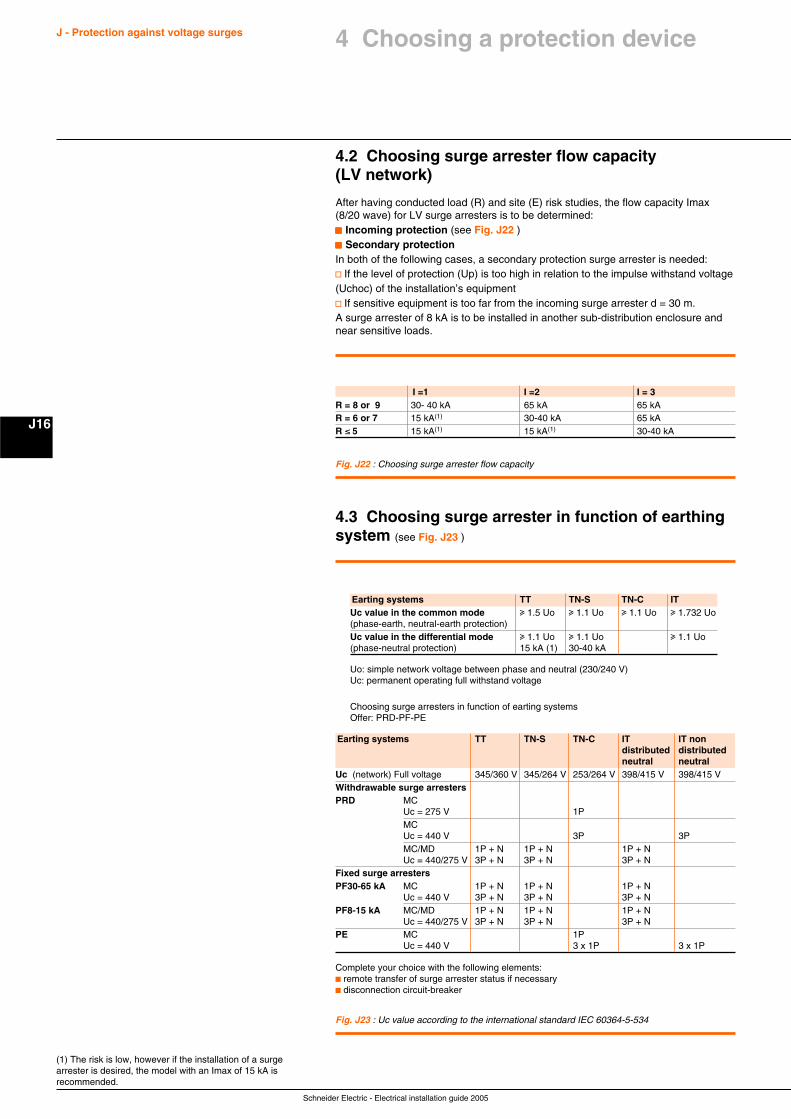
Schneider Electric - Electrical installation guide 2005
J - Protection against voltage surges
J16
(1) The risk is low, however if the installation of a surgearrester is desired, the model with an Imax of 15 kA isrecommended.
I =1 I =2 I = 3R = 8 or 9 30- 40 kA 65 kA 65 kAR = 6 or 7 15 kA(1) 30-40 kA 65 kAR ≤ 5 15 kA(1) 15 kA(1) 30-40 kA
Fig. J22 : Choosing surge arrester flow capacity
Uo: simple network voltage between phase and neutral (230/240 V)Uc: permanent operating full withstand voltage
Choosing surge arresters in function of earting systemsOffer: PRD-PF-PE
4.2 Choosing surge arrester flow capacity(LV network)
After having conducted load (R) and site (E) risk studies, the flow capacity Imax(8/20 wave) for LV surge arresters is to be determined:ccccc Incoming protection (see Fig. J22 )ccccc Secondary protectionIn both of the following cases, a secondary protection surge arrester is needed:v If the level of protection (Up) is too high in relation to the impulse withstand voltage(Uchoc) of the installation’s equipmentv If sensitive equipment is too far from the incoming surge arrester d = 30 m.A surge arrester of 8 kA is to be installed in another sub-distribution enclosure andnear sensitive loads.
Earting systems TT TN-S TN-C ITUc value in the common mode u 1.5 Uo u 1.1 Uo u 1.1 Uo u 1.732 Uo(phase-earth, neutral-earth protection)Uc value in the differential mode u 1.1 Uo u 1.1 Uo u 1.1 Uo(phase-neutral protection) 15 kA (1) 30-40 kA
Complete your choice with the following elements:c remote transfer of surge arrester status if necessaryc disconnection circuit-breaker
Fig. J23 : Uc value according to the international standard IEC 60364-5-534
Earting systems TT TN-S TN-C IT IT nondistributed distributedneutral neutral
Uc (network) Full voltage 345/360 V 345/264 V 253/264 V 398/415 V 398/415 VWithdrawable surge arrestersPRD MC
Uc = 275 V 1PMCUc = 440 V 3P 3PMC/MD 1P + N 1P + N 1P + NUc = 440/275 V 3P + N 3P + N 3P + N
Fixed surge arrestersPF30-65 kA MC 1P + N 1P + N 1P + N
Uc = 440 V 3P + N 3P + N 3P + NPF8-15 kA MC/MD 1P + N 1P + N 1P + N
Uc = 440/275 V 3P + N 3P + N 3P + NPE MC 1P
Uc = 440 V 3 x 1P 3 x 1P
4.3 Choosing surge arrester in function of earthingsystem (see Fig. J23 )
4 Choosing a protection device
Schneider Electric - Electrical installation guide 2005
J17
J - Protection against voltage surges
Fig. J24 : Choosing a disconnection circuit-breaker
4 Choosing a protection device
Full discharge current for Disconnectionsurge arresters circuit-breaker
Rating Curve8-15-30-40 kA 20 A C65 kA 50 A C
4.4 Choosing a disconnection circuit breaker(see Fig. J24 )
After having chosen the surge arrester(s) needed to protect the installation, theappropriate disconnection circuit-breaker is to be chosen from the table below:c Its breaking capacity must be compatible with the installation’s breaking capacityc Each live conductor must be protected, for example: a surge arrester 1P+N mustbe associated with a 2-pole disconnection circuit-breaker (2 protected poles).
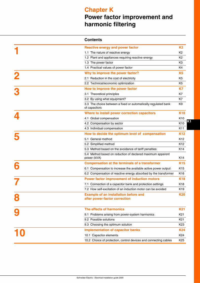
Schneider Electric - Electrical installation guide 2005
K1
Chapter KPower factor improvement andharmonic filtering
Contents
Reactive energy and power factor K2
1.1 The nature of reactive energy K2
1.2 Plant and appliances requiring reactive energy K2
1.3 The power factor K3
1.4 Practical values of power factor K4
Why to improve the power factor? K5
2.1 Reduction in the cost of electricity K5
2.2 Technical/economic optimization K5
How to improve the power factor K7
3.1 Theoretical principles K7
3.2 By using what equipment? K7
3.3 The choice between a fixed or automatically-regulated bank K9of capacitors
Where to install power correction capacitors K10
4.1 Global compensation K10
4.2 Compensation by sector K10
4.3 Individual compensation K11
How to decide the optimum level of compensation K12
5.1 General method K12
5.2 Simplified method K12
5.3 Method based on the avoidance of tariff penalties K14
5.4 Method based on reduction of declared maximum apparentpower (kVA) K14
Compensation at the terminals of a transformer K15
6.1 Compensation to increase the available active power output K15
6.2 Compensation of reactive energy absorbed by the transformer K16
Power factor improvement of induction motors K18
7.1 Connection of a capacitor bank and protection settings K18
7.2 How self-excitation of an induction motor can be avoided K19
Example of an installation before and K20after power-factor correction
The effects of harmonics K21
9.1 Problems arising from power-system harmonics K21
9.2 Possible solutions K21
9.3 Choosing the optimum solution K23
Implementation of capacitor banks K24
10.1 Capacitor elements K24
10.2 Choice of protection, control devices and connecting cables K25
1
2
3
4
5
6
7
89
10
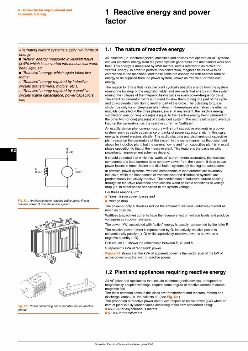
Schneider Electric - Electrical installation guide 2005
K - Power factor improvement andharmonic filtering
K2
1 Reactive energy and powerfactor
Alternating current systems supply two forms ofenergy:c “Active” energy measured in kilowatt hours(kWh) which is converted into mechanical work,heat, light, etcc “Reactive” energy, which again takes twoforms:v “Reactive” energy required by inductivecircuits (transformers, motors, etc.),v “Reactive” energy required by capacitivecircuits (cable capacitance, power capacitors,etc)
1.1 The nature of reactive energy
All inductive (i.e. electromagnetic) machines and devices that operate on AC systemsconvert electrical energy from the powersystem generators into mechanical work andheat. This energy is measured by kWh meters, and is referred to as “active” or“wattful” energy. In order to perform this conversion, magnetic fields have to beestablished in the machines, and these fields are associated with another form ofenergy to be supplied from the power system, known as “reactive” or “wattless”energy.
The reason for this is that inductive plant cyclically absorbs energy from the system(during the build-up of the magnetic fields) and re-injects that energy into the system(during the collapse of the magnetic fields) twice in every power-frequency cycle.The effect on generator rotors is to (tend to) slow them during one part of the cycleand to accelerate them during another part of the cycle. The pulsating torque isstricly true only for single-phase alternators. In three-phase alternators the effect ismutually cancelled in the three phases, since, at any instant, the reactive energysupplied on one (or two) phase(s) is equal to the reactive energy being returned onthe other two (or one) phase(s) of a balanced system. The nett result is zero averageload on the generators, i.e. the reactive current is “wattless”.
An exactly similar phenomenon occurs with shunt capacitive elements in a powersystem, such as cable capacitance or banks of power capacitors, etc. In this case,energy is stored electrostatically. The cyclic charging and discharging of capacitiveplant reacts on the generators of the system in the same manner as that describedabove for inductive plant, but the current flow to and from capacitive plant is in exactphase opposition to that of the inductive plant. This feature is the basis on whichpowerfactor improvement schemes depend.
It should be noted that while this “wattless” current (more accurately, the wattlesscomponent of a load current) does not draw power from the system, it does causepower losses in transmission and distribution systems by heating the conductors.
In practical power systems, wattless components of load currents are invariablyinductive, while the impedances of transmission and distribution systems arepredominantly inductively reactive. The combination of inductive current passingthrough an inductive reactance produces the worst possible conditions of voltagedrop (i.e. in direct phase opposition to the system voltage).
For these reasons, viz:c Transmission power losses andc Voltage drop
The power-supply authorities reduce the amount of wattless (inductive) current asmuch as possible.
Wattless (capacitive) currents have the reverse effect on voltage levels and producevoltage-rises in power systems.
The power (kW) associated with “active” energy is usually represented by the letter P.
The reactive power (kvar) is represented by Q. Inductively-reactive power isconventionally positive (+ Q) while capacitively-reactive power is shown as anegative quantity (- Q).
Sub-clause 1.3 shows the relationship between P, Q, and S.
S represents kVA of “apparent” power.
Figure K1 shows that the kVA of apparent power is the vector sum of the kW ofactive power plus the kvar of reactive power.
1.2 Plant and appliances requiring reactive energy
All AC plant and appliances that include electromagnetic devices, or depend onmagnetically-coupled windings, require some degree of reactive current to createmagnetic flux.The most common items in this class are transformers and reactors, motors anddischarge lamps (i.e. the ballasts of) (see Fig. K2 ).The proportion of reactive power (kvar) with respect to active power (kW) when anitem of plant is fully loaded varies according to the item concerned being:c 65-75% for asynchronous motorsc 5-10% for transformers
Q(kvar)
S(kVA)
P(kW)
Fig. K1 : An electric motor requires active power P andreactive power Q from the power system
Fig. K2 : Power consuming items that also require reactiveenergy
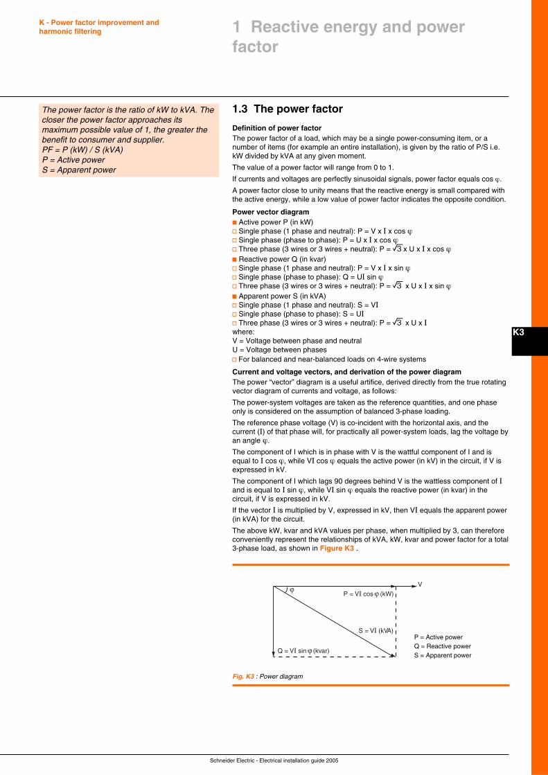
Schneider Electric - Electrical installation guide 2005
K - Power factor improvement andharmonic filtering
K3
1.3 The power factor
Definition of power factorThe power factor of a load, which may be a single power-consuming item, or anumber of items (for example an entire installation), is given by the ratio of P/S i.e.kW divided by kVA at any given moment.
The value of a power factor will range from 0 to 1.
If currents and voltages are perfectly sinusoidal signals, power factor equals cos ϕ.
A power factor close to unity means that the reactive energy is small compared withthe active energy, while a low value of power factor indicates the opposite condition.
Power vector diagramc Active power P (in kW)v Single phase (1 phase and neutral): P = V x I x cos ϕv Single phase (phase to phase): P = U x I x cos ϕv Three phase (3 wires or 3 wires + neutral): P = ex U x I x cos ϕc Reactive power Q (in kvar)v Single phase (1 phase and neutral): P = V x I x sin ϕv Single phase (phase to phase): Q = UI sin ϕv Three phase (3 wires or 3 wires + neutral): P = e x U x I x sin ϕc Apparent power S (in kVA)v Single phase (1 phase and neutral): S = VIv Single phase (phase to phase): S = UIv Three phase (3 wires or 3 wires + neutral): P = e x U x Iwhere:V = Voltage between phase and neutralU = Voltage between phasesv For balanced and near-balanced loads on 4-wire systems
Current and voltage vectors, and derivation of the power diagramThe power “vector” diagram is a useful artifice, derived directly from the true rotatingvector diagram of currents and voltage, as follows:
The power-system voltages are taken as the reference quantities, and one phaseonly is considered on the assumption of balanced 3-phase loading.
The reference phase voltage (V) is co-incident with the horizontal axis, and thecurrent (I) of that phase will, for practically all power-system loads, lag the voltage byan angle ϕ.
The component of I which is in phase with V is the wattful component of I and isequal to I cos ϕ, while VI cos ϕ equals the active power (in kV) in the circuit, if V isexpressed in kV.
The component of I which lags 90 degrees behind V is the wattless component of Iand is equal to I sin ϕ, while VI sin ϕ equals the reactive power (in kvar) in thecircuit, if V is expressed in kV.
If the vector I is multiplied by V, expressed in kV, then VI equals the apparent power(in kVA) for the circuit.
The above kW, kvar and kVA values per phase, when multiplied by 3, can thereforeconveniently represent the relationships of kVA, kW, kvar and power factor for a total3-phase load, as shown in Figure K3 .
1 Reactive energy and powerfactor
The power factor is the ratio of kW to kVA. Thecloser the power factor approaches itsmaximum possible value of 1, the greater thebenefit to consumer and supplier.PF = P (kW) / S (kVA)P = Active powerS = Apparent power
Fig. K3 : Power diagram
P = Active powerQ = Reactive powerS = Apparent power
Q = VI sin ϕ (kvar)
S = VI (kVA)
Vϕ
P = VI cos ϕ (kW)
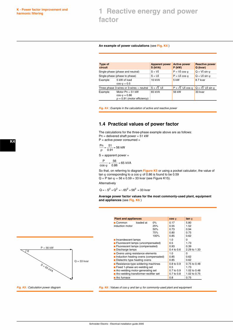
Schneider Electric - Electrical installation guide 2005
K - Power factor improvement andharmonic filtering
K4
Fig. K4 : Example in the calculation of active and reactive power
An example of power calculations (see Fig. K4 )
Type of Apparent power Active power Reactive powercircuit S (kVA) P (kW) Q (kvar)
Single-phase (phase and neutral) S = VI P = VI cos ϕ Q = VI sin ϕSingle-phase (phase to phase) S = UI P = UI cos ϕ Q = UI sin ϕExample 5 kW of load 10 kVA 5 kW 8.7 kvar
cos ϕ = 0.5
Three phase 3-wires or 3-wires + neutral S = e UI P = e UI cos ϕ Q = e UI sin ϕExample Motor Pn = 51 kW 65 kVA 56 kW 33 kvar
cos ϕ = 0.86ρ = 0.91 (motor efficiency)
1.4 Practical values of power factor
The calculations for the three-phase example above are as follows:Pn = delivered shaft power = 51 kWP = active power consumed =
Pn56 kW
ρ= =
510 91.
S = apparent power =
Pcos
6 kVAϕ
= =56
0 865
.
So that, on referring to diagram Figure K5 or using a pocket calculator, the value oftan ϕ corresponding to a cos ϕ of 0.86 is found to be 0.59Q = P tan ϕ = 56 x 0.59 = 33 kvar (see Figure K15).
Alternatively
Q 65 56 33 kvar2= + = + =S Q2 2 2
Average power factor values for the most commonly-used plant, equipmentand appliances (see Fig. K6 )
Plant and appliances cos ϕ tan ϕc Common loaded at 0% 0.17 5.80induction motor 25% 0.55 1.52
50% 0.73 0.9475% 0.80 0.75100% 0.85 0.62
c Incandescent lamps 1.0 0c Fluorescent lamps (uncompensated) 0.5 1.73c Fluorescent lamps (compensated) 0.93 0.39c Discharge lamps 0.4 to 0.6 2.29 to 1.33c Ovens using resistance elements 1.0 0c Induction heating ovens (compensated) 0.85 0.62c Dielectric type heating ovens 0.85 0.62c Resistance-type soldering machines 0.8 to 0.9 0.75 to 0.48c Fixed 1-phase arc-welding set 0.5 1.73c Arc-welding motor-generating set 0.7 to 0.9 1.02 to 0.48c Arc-welding transformer-rectifier set 0.7 to 0.8 1.02 to 0.75c Arc furnace 0.8 0.75
Fig. K6 : Values of cos ϕ and tan ϕ for commonly-used plant and equipment
1 Reactive energy and powerfactor
Q = 33 kvar
ϕP = 56 kW
S = 65 kVA
Fig. K5 : Calculation power diagram
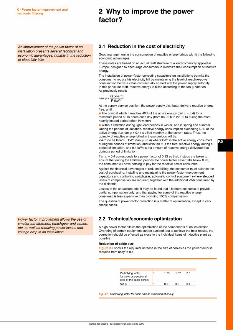
Schneider Electric - Electrical installation guide 2005
K - Power factor improvement andharmonic filtering
K5
2.1 Reduction in the cost of electricity
Good management in the consumption of reactive energy brings with it the followingeconomic advantages.
These notes are based on an actual tariff structure of a kind commonly applied inEurope, designed to encourage consumers to minimize their consumption of reactiveenergy.
The installation of power-factor correcting capacitors on installations permits theconsumer to reduce his electricity bill by maintaining the level of reactive-powerconsumption below a value contractually agreed with the power supply authority.In this particular tariff, reactive energy is billed according to the tan ϕ criterion.As previously noted:
tan Q (kvarh)P (kWh)
ϕ =
At the supply service position, the power supply distributor delivers reactive energyfree, until:c The point at which it reaches 40% of the active energy (tan ϕ = 0.4) for amaximum period of 16 hours each day (from 06-00 h to 22-00 h) during the most-heavily loaded period (often in winter)c Without limitation during light-load periods in winter, and in spring and summer.During the periods of limitation, reactive energy consumption exceeding 40% of theactive energy (i.e. tan ϕ > 0.4) is billed monthly at the current rates. Thus, thequantity of reactive energy billed in these periods will be:kvarh (to be billed) = kWh (tan ϕ - 0.4) where kWh is the active energy consumedduring the periods of limitation, and kWh tan ϕ is the total reactive energy during aperiod of limitation, and 0.4 kWh is the amount of reactive energy delivered freeduring a period of limitation.
Tan ϕ = 0.4 corresponds to a power factor of 0.93 so that, if steps are taken toensure that during the limitation periods the power factor never falls below 0.93,the consumer will have nothing to pay for the reactive power consumed.
Against the financial advantages of reduced billing, the consumer must balance thecost of purchasing, installing and maintaining the power-factor-improvementcapacitors and controlling switchgear, automatic control equipment (where steppedlevels of compensation are required) together with the additional kWh consumed bythe dielectric.
Losses of the capacitors, etc. It may be found that it is more economic to providepartial compensation only, and that paying for some of the reactive energyconsumed is less expensive than providing 100% compensation.
The question of power-factor correction is a matter of optimization, except in verysimple cases.
2.2 Technical/economic optimization
A high power factor allows the optimization of the components of an installation.Overating of certain equipment can be avoided, but to achieve the best results, thecorrection should be effected as close to the individual items of inductive plant aspossible.
Reduction of cable sizeFigure K7 shows the required increase in the size of cables as the power factor isreduced from unity to 0.4.
An improvement of the power factor of aninstallation presents several technical andeconomic advantages, notably in the reductionof electricity bills
2 Why to improve the powerfactor?
Power factor improvement allows the use ofsmaller transformers, switchgear and cables,etc. as well as reducing power losses andvoltage drop in an installation
Fig. K7 : Multiplying factor for cable size as a function of cos ϕ
Multiplying factor 1 1.25 1.67 2.5for the cross-sectionalarea of the cable core(s)
cos ϕ 1 0.8 0.6 0.4

Schneider Electric - Electrical installation guide 2005
K - Power factor improvement andharmonic filtering
K6
2 Why to improve the powerfactor?
(1) Since other benefits accrue from a high value of powerfactor, as previously noted.
Reduction of losses (P, kW) in cablesLosses in cables are proportional to the current squared, and are measured by thekWh meter for the installation. Reduction of the total current in a conductor by 10%for example, will reduce the losses by almost 20%.
Reduction of voltage dropPower factor correction capacitors reduce or even cancel completely the (inductive)reactive current in upstream conductors, thereby reducing or eliminating voltagedrops.
Note: Overcompensation will produce a voltage rise at the capacitors.
Increase in available powerBy improving the power factor of a load supplied from a transformer, the currentthrough the transformer will be reduced, thereby allowing more load to be added. Inpractice, it may be less expensive to improve the power factor (1), than to replace thetransformer by a larger unit.
This matter is further elaborated in clause 6.
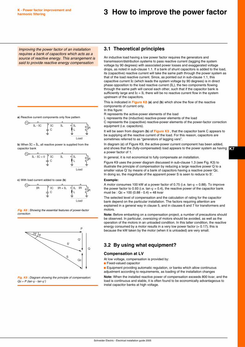
Schneider Electric - Electrical installation guide 2005
K7
3 How to improve the power factor
3.1 Theoretical principles
An inductive load having a low power factor requires the generators andtransmission/distribution systems to pass reactive current (lagging the systemvoltage by 90 degrees) with associated power losses and exaggerated voltagedrops, as noted in sub-clause 1.1. If a bank of shunt capacitors is added to the load,its (capacitive) reactive current will take the same path through the power system asthat of the load reactive current. Since, as pointed out in sub-clause 1.1, thiscapacitive current Ic (which leads the system voltage by 90 degrees) is in directphase opposition to the load reactive current (IL), the two components flowingthrough the same path will cancel each other, such that if the capacitor bank issufficiently large and Ic = IL there will be no reactive current flow in the systemupstream of the capacitors.
This is indicated in Figure K8 (a) and (b) which show the flow of the reactivecomponents of current only.In this figure:R represents the active-power elements of the loadL represents the (inductive) reactive-power elements of the loadC represents the (capacitive) reactive-power elements of the power-factor correctionequipment (i.e. capacitors).
It will be seen from diagram (b) of Figure K9 , that the capacitor bank C appears tobe supplying all the reactive current of the load. For this reason, capacitors aresometimes referred to as “generators of lagging vars”.
In diagram (c) of Figure K9, the active-power current component has been added,and shows that the (fully-compensated) load appears to the power system as havinga power factor of 1.
In general, it is not economical to fully compensate an installation.
Figure K9 uses the power diagram discussed in sub-clause 1.3 (see Fig. K3) toillustrate the principle of compensation by reducing a large reactive power Q to asmaller value Q’ by means of a bank of capacitors having a reactive power Qc.In doing so, the magnitude of the apparent power S is seen to reduce to S’.
Example:A motor consumes 100 kW at a power factor of 0.75 (i.e. tan ϕ = 0.88). To improvethe power factor to 0.93 (i.e. tan ϕ = 0.4), the reactive power of the capacitor bankmust be : Qc = 100 (0.88 - 0.4) = 48 kvar
The selected level of compensation and the calculation of rating for the capacitorbank depend on the particular installation. The factors requiring attention areexplained in a general way in clause 5, and in clauses 6 and 7 for transformers andmotors.
Note: Before embarking on a compensation project, a number of precautions shouldbe observed. In particular, oversizing of motors should be avoided, as well as theoperation of the motors in an unloaded condition. In this latter condition, the reactiveenergy consumed by a motor results in a very low power factor (≈ 0.17); this isbecause the kW taken by the motor (when it is unloaded) are very small.
3.2 By using what equipment?
Compensation at LVAt low voltage, compensation is provided by:c Fixed-valued capacitorc Equipment providing automatic regulation, or banks which allow continuousadjustment according to requirements, as loading of the installation changes
Note: When the installed reactive power of compensation exceeds 800 kvar, and theload is continuous and stable, it is often found to be economically advantageous toinstal capacitor banks at high voltage.
Improving the power factor of an installationrequires a bank of capacitors which acts as asource of reactive energy. This arrangement issaid to provide reactive energy compensation
C LR
IL - IC IL ILIC
Load
C LR
IL - IC = 0 IL ILIC
Load
C LR
IR IRIR + IL ILIC
Load
a) Reactive current components only flow pattern
b) When IC = IL, all reactive power is supplied from thecapacitor bank
c) With load current added to case (b)
Fig. K8 : Showing the essential features of power-factorcorrection
Qc
ϕϕ'
P
S
S'
Q
Q'
Fig. K9 : Diagram showing the principle of compensation:Qc = P (tan ϕ - tan ϕ’)
K - Power factor improvement andharmonic filtering
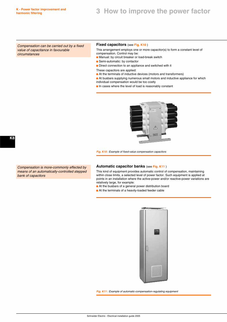
Schneider Electric - Electrical installation guide 2005
K - Power factor improvement andharmonic filtering
K8
Fixed capacitors (see Fig. K10 )
This arrangement employs one or more capacitor(s) to form a constant level ofcompensation. Control may be:c Manual: by circuit breaker or load-break switchc Semi-automatic: by contactorc Direct connection to an appliance and switched with it
These capacitors are applied:c At the terminals of inductive devices (motors and transformers)c At busbars supplying numerous small motors and inductive appliance for whichindividual compensation would be too costlyc In cases where the level of load is reasonably constant
Compensation can be carried out by a fixedvalue of capacitance in favourablecircumstances
Compensation is more-commonly effected bymeans of an automatically-controlled steppedbank of capacitors
Fig. K11 : Example of automatic-compensation-regulating equipment
Automatic capacitor banks (see Fig. K11 )
This kind of equipment provides automatic control of compensation, maintainingwithin close limits, a selected level of power factor. Such equipment is applied atpoints in an installation where the active-power and/or reactive-power variations arerelatively large, for example:c At the busbars of a general power distribution boardc At the terminals of a heavily-loaded feeder cable
Fig. K10 : Example of fixed-value compensation capacitors
3 How to improve the power factor
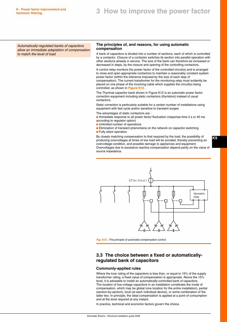
Schneider Electric - Electrical installation guide 2005
K - Power factor improvement andharmonic filtering
K9
The principles of, and reasons, for using automaticcompensationA bank of capacitors is divided into a number of sections, each of which is controlledby a contactor. Closure of a contactor switches its section into parallel operation withother sections already in service. The size of the bank can therefore be increased ordecreased in steps, by the closure and opening of the controlling contactors.
A control relay monitors the power factor of the controlled circuit(s) and is arrangedto close and open appropriate contactors to maintain a reasonably constant systempower factor (within the tolerance imposed by the size of each step ofcompensation). The current transformer for the monitoring relay must evidently beplaced on one phase of the incoming cable which supplies the circuit(s) beingcontrolled, as shown in Figure K12 .
The Thyrimat capacitor bank shown in Figure K12 is an automatic power factorcorrection equipment including static contactors (thyristors) instead of usualcontactors.
Static correction is particularly suitable for a certain number of installations usingequipment with fast cycle and/or sensitive to transient surges.
The advantages of static contactors are :c Immediate response to all power factor fluctuation (response time 2 s or 40 msaccording to regulator option)c Unlimited number of operationsc Elimination of transient phenomena on the network on capacitor switchingc Fully silant operation
By closely matching compensation to that required by the load, the possibility ofproducing overvoltages at times of low load will be avoided, thereby preventing anovervoltage condition, and possible damage to appliances and equipment.Overvoltages due to excessive reactive compensation depend partly on the value ofsource impedance.
Automatically-regulated banks of capacitorsallow an immediate adaptation of compensationto match the level of load
Varmetricrelay
CT In / 5 A cl 1
Fig. K12 : The principle of automatic-compensation control
3.3 The choice between a fixed or automatically-regulated bank of capacitors
Commonly-applied rulesWhere the kvar rating of the capacitors is less than, or equal to 15% of the supplytransformer rating, a fixed value of compensation is appropriate. Above the 15%level, it is advisable to install an automatically-controlled bank of capacitors.The location of low-voltage capacitors in an installation constitutes the mode ofcompensation, which may be global (one location for the entire installation), partial(section-by-section), local (at each individual device), or some combination of thelatter two. In principle, the ideal compensation is applied at a point of consumptionand at the level required at any instant.
In practice, technical and economic factors govern the choice.
3 How to improve the power factor
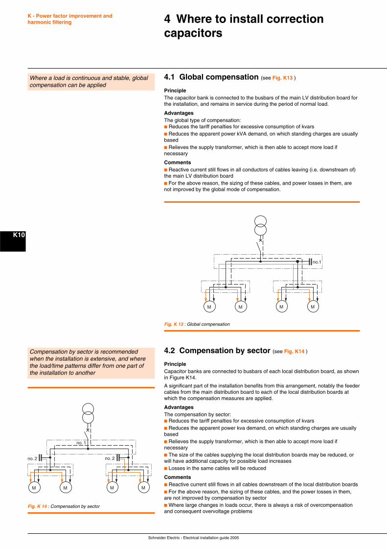
Schneider Electric - Electrical installation guide 2005
K - Power factor improvement andharmonic filtering
K10
4 Where to install correctioncapacitors
Where a load is continuous and stable, globalcompensation can be applied
4.1 Global compensation (see Fig. K13 )
PrincipleThe capacitor bank is connected to the busbars of the main LV distribution board forthe installation, and remains in service during the period of normal load.
AdvantagesThe global type of compensation:c Reduces the tariff penalties for excessive consumption of kvarsc Reduces the apparent power kVA demand, on which standing charges are usuallybasedc Relieves the supply transformer, which is then able to accept more load ifnecessary
Commentsc Reactive current still flows in all conductors of cables leaving (i.e. downstream of)the main LV distribution boardc For the above reason, the sizing of these cables, and power losses in them, arenot improved by the global mode of compensation.
Fig. K 14 : Compensation by sector
Compensation by sector is recommendedwhen the installation is extensive, and wherethe load/time patterns differ from one part ofthe installation to another
M M M M
no. 2 no. 2
no. 1
4.2 Compensation by sector (see Fig. K14 )
PrincipleCapacitor banks are connected to busbars of each local distribution board, as shownin Figure K14.
A significant part of the installation benefits from this arrangement, notably the feedercables from the main distribution board to each of the local distribution boards atwhich the compensation measures are applied.
AdvantagesThe compensation by sector:c Reduces the tariff penalties for excessive consumption of kvarsc Reduces the apparent power kva demand, on which standing charges are usuallybasedc Relieves the supply transformer, which is then able to accept more load ifnecessaryc The size of the cables supplying the local distribution boards may be reduced, orwill have additional capacity for possible load increasesc Losses in the same cables will be reduced
Commentsc Reactive current still flows in all cables downstream of the local distribution boardsc For the above reason, the sizing of these cables, and the power losses in them,are not improved by compensation by sectorc Where large changes in loads occur, there is always a risk of overcompensationand consequent overvoltage problems
Fig. K 13 : Global compensation
M M M M
no.1
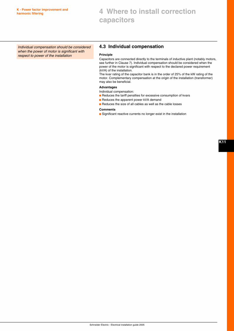
Schneider Electric - Electrical installation guide 2005
K - Power factor improvement andharmonic filtering
K11
Individual compensation should be consideredwhen the power of motor is significant withrespect to power of the installation
4.3 Individual compensation
PrincipleCapacitors are connected directly to the terminals of inductive plant (notably motors,see further in Clause 7). Individual compensation should be considered when thepower of the motor is significant with respect to the declared power requirement(kVA) of the installation.The kvar rating of the capacitor bank is in the order of 25% of the kW rating of themotor. Complementary compensation at the origin of the installation (transformer)may also be beneficial.
AdvantagesIndividual compensation:c Reduces the tariff penalties for excessive consumption of kvarsc Reduces the apparent power kVA demandc Reduces the size of all cables as well as the cable losses
Commentsc Significant reactive currents no longer exist in the installation
4 Where to install correctioncapacitors
Schneider Electric - Electrical installation guide 2005
K - Power factor improvement andharmonic filtering
K12
5.1 General method
Listing of reactive power demands at the design stageThis listing can be made in the same way (and at the same time) as that for thepower loading described in chapter B. The levels of active and reactive powerloading, at each level of the installation (generally at points of distribution and sub-distribution of circuits) can then be determined.
Technical-economic optimization for an existing installationThe optimum rating of compensation capacitors for an existing installation can bedetermined from the following principal considerations:c Electricity bills prior to the installation of capacitorsc Future electricity bills anticipated following the installation of capacitorsc Costs of:v Purchase of capacitors and control equipment (contactors, relaying, cabinets, etc.)v Installation and maintenance costsv Cost of dielectric heating losses in the capacitors, versus reduced losses in cables,transformer, etc., following the installation of capacitors
Several simplified methods applied to typical tariffs (common in Europe) are shownin sub-clauses 5.3 and 5.4.
5.2 Simplified method
General principleAn approximate calculation is generally adequate for most practical cases, and maybe based on the assumption of a power factor of 0.8 (lagging) before compensation.In order to improve the power factor to a value sufficient to avoid tariff penalties (thisdepends on local tariff structures, but is assumed here to be 0.93) and to reducelosses, volt-drops, etc. in the installation, reference can be made to Figure K15 nextpage.
From the figure, it can be seen that, to raise the power factor of the installation from0.8 to 0.93 will require 0.355 kvar per kW of load. The rating of a bank of capacitorsat the busbars of the main distribution board of the installation would be
Q (kvar) = 0.355 x P (kW).
This simple approach allows a rapid determination of the compensation capacitorsrequired, albeit in the global, partial or independent mode.
ExampleIt is required to improve the power factor of a 666 kVA installation from 0.75 to0.928. The active power demand is 666 x 0.75 = 500 kW.In Figure K17, the intersection of the row cos ϕ = 0.75 (before correction) with thecolumn cos ϕ = 0.93 (after correction) indicates a value of 0.487 kvar ofcompensation per kW of load.For a load of 500 kW, therefore, 500 x 0.487 = 244 kvar of capacitive compensationis required.
Note: this method is valid for any voltage level, i.e. is independent of voltage.
5 How to decide the optimum levelof compensation
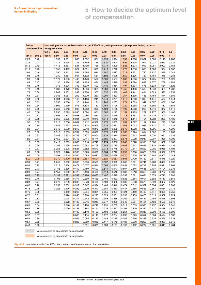
Schneider Electric - Electrical installation guide 2005
K - Power factor improvement andharmonic filtering
K13
5 How to decide the optimum levelof compensation
Before kvar rating of capacitor bank to install per kW of load, to improve cos ϕ (the power factor) or tan ϕ,compensation to a given value
tan ϕ 0.75 0.59 0.48 0.46 0.43 0.40 0.36 0.33 0.29 0.25 0.20 0.14 0.0
tan ϕ cos ϕ cos ϕ 0.80 0.86 0.90 0.91 0.92 0.93 0.94 0.95 0.96 0.97 0.98 0.99 12.29 0.40 1.557 1.691 1.805 1.832 1.861 1.895 1.924 1.959 1.998 2.037 2.085 2.146 2.2882.22 0.41 1.474 1.625 1.742 1.769 1.798 1.831 1.840 1.896 1.935 1.973 2.021 2.082 2.2252.16 0.42 1.413 1.561 1.681 1.709 1.738 1.771 1.800 1.836 1.874 1.913 1.961 2.022 2.1642.10 0.43 1.356 1.499 1.624 1.651 1.680 1.713 1.742 1.778 1.816 1.855 1.903 1.964 2.1072.04 0.44 1.290 1.441 1.558 1.585 1.614 1.647 1.677 1.712 1.751 1.790 1.837 1.899 2.0411.98 0.45 1.230 1.384 1.501 1.532 1.561 1.592 1.628 1.659 1.695 1.737 1.784 1.846 1.9881.93 0.46 1.179 1.330 1.446 1.473 1.502 1.533 1.567 1.600 1.636 1.677 1.725 1.786 1.9291.88 0.47 1.130 1.278 1.397 1.425 1.454 1.485 1.519 1.532 1.588 1.629 1.677 1.758 1.8811.83 0.48 1.076 1.228 1.343 1.370 1.400 1.430 1.464 1.497 1.534 1.575 1.623 1.684 1.8261.78 0.49 1.030 1.179 1.297 1.326 1.355 1.386 1.420 1.453 1.489 1.530 1.578 1.639 1.7821.73 0.50 0.982 1.232 1.248 1.276 1.303 1.337 1.369 1.403 1.441 1.481 1.529 1.590 1.7321.69 0.51 0.936 1.087 1.202 1.230 1.257 1.291 1.323 1.357 1.395 1.435 1.483 1.544 1.6861.64 0.52 0.894 1.043 1.160 1.188 1.215 1.249 1.281 1.315 1.353 1.393 1.441 1.502 1.6441.60 0.53 0.850 1.000 1.116 1.144 1.171 1.205 1.237 1.271 1.309 1.349 1.397 1.458 1.6001.56 0.54 0.809 0.959 1.075 1.103 1.130 1.164 1.196 1.230 1.268 1.308 1.356 1.417 1.5591.52 0.55 0.769 0.918 1.035 1.063 1.090 1.124 1.156 1.190 1.228 1.268 1.316 1.377 1.5191.48 0.56 0.730 0.879 0.996 1.024 1.051 1.085 1.117 1.151 1.189 1.229 1.277 1.338 1.4801.44 0.57 0.692 0.841 0.958 0.986 1.013 1.047 1.079 1.113 1.151 1.191 1.239 1.300 1.4421.40 0.58 0.665 0.805 0.921 0.949 0.976 1.010 1.042 1.076 1.114 1.154 1.202 1.263 1.4051.37 0.59 0.618 0.768 0.884 0.912 0.939 0.973 1.005 1.039 1.077 1.117 1.165 1.226 1.3681.33 0.60 0.584 0.733 0.849 0.878 0.905 0.939 0.971 1.005 1.043 1.083 1.131 1.192 1.3341.30 0.61 0.549 0.699 0.815 0.843 0.870 0.904 0.936 0.970 1.008 1.048 1.096 1.157 1.2991.27 0.62 0.515 0.665 0.781 0.809 0.836 0.870 0.902 0.936 0.974 1.014 1.062 1.123 1.2651.23 0.63 0.483 0.633 0.749 0.777 0.804 0.838 0.870 0.904 0.942 0.982 1.030 1.091 1.2331.20 0.64 0.450 0.601 0.716 0.744 0.771 0.805 0.837 0.871 0.909 0.949 0.997 1.058 1.2001.17 0.65 0.419 0.569 0.685 0.713 0.740 0.774 0.806 0.840 0.878 0.918 0.966 1.007 1.1691.14 0.66 0.388 0.538 0.654 0.682 0.709 0.743 0.775 0.809 0.847 0.887 0.935 0.996 1.1381.11 0.67 0.358 0.508 0.624 0.652 0.679 0.713 0.745 0.779 0.817 0.857 0.905 0.966 1.1081.08 0.68 0.329 0.478 0.595 0.623 0.650 0.684 0.716 0.750 0.788 0.828 0.876 0.937 1.0791.05 0.69 0.299 0.449 0.565 0.593 0.620 0.654 0.686 0.720 0.758 0.798 0.840 0.907 1.0491.02 0.70 0.270 0.420 0.536 0.564 0.591 0.625 0.657 0.691 0.729 0.769 0.811 0.878 1.0200.99 0.71 0.242 0.392 0.508 0.536 0.563 0.597 0.629 0.663 0.701 0.741 0.783 0.850 0.9920.96 0.72 0.213 0.364 0.479 0.507 0.534 0.568 0.600 0.634 0.672 0.712 0.754 0.821 0.9630.94 0.73 0.186 0.336 0.452 0.480 0.507 0.541 0.573 0.607 0.645 0.685 0.727 0.794 0.9360.91 0.74 0.159 0.309 0.425 0.453 0.480 0.514 0.546 0.580 0.618 0.658 0.700 0.767 0.9090.88 0.75 0.132 0.82 0.398 0.426 0.453 0.487 0.519 0.553 0.591 0.631 0.673 0.740 0.8820.86 0.76 0.105 0.255 0.371 0.399 0.426 0.460 0.492 0.526 0.564 0.604 0.652 0.713 0.8550.83 0.77 0.079 0.229 0.345 0.373 0.400 0.434 0.466 0.500 0.538 0.578 0.620 0.687 0.8290.80 0.78 0.053 0.202 0.319 0.347 0.374 0.408 0.440 0.474 0.512 0.552 0.594 0.661 0.8030.78 0.79 0.026 0.176 0.292 0.320 0.347 0.381 0.413 0.447 0.485 0.525 0.567 0.634 0.7760.75 0.80 0.150 0.266 0.294 0.321 0.355 0.387 0.421 0.459 0.499 0.541 0.608 0.7500.72 0.81 0.124 0.240 0.268 0.295 0.329 0.361 0.395 0.433 0.473 0.515 0.582 0.7240.70 0.82 0.098 0.214 0.242 0.269 0.303 0.335 0.369 0.407 0.447 0.489 0.556 0.6980.67 0.83 0.072 0.188 0.216 0.243 0.277 0.309 0.343 0.381 0.421 0.463 0.530 0.6720.65 0.84 0.046 0.162 0.190 0.217 0.251 0.283 0.317 0.355 0.395 0.437 0.504 0.6450.62 0.85 0.020 0.136 0.164 0.191 0.225 0.257 0.291 0.329 0.369 0.417 0.478 0.6200.59 0.86 0.109 0.140 0.167 0.198 0.230 0.264 0.301 0.343 0.390 0.450 0.5930.57 0.87 0.083 0.114 0.141 0.172 0.204 0.238 0.275 0.317 0.364 0.424 0.5670.54 0.88 0.054 0.085 0.112 0.143 0.175 0.209 0.246 0.288 0.335 0.395 0.5380.51 0.89 0.028 0.059 0.086 0.117 0.149 0.183 0.230 0.262 0.309 0.369 0.5120.48 0.90 0.031 0.058 0.089 0.121 0.155 0.192 0.234 0.281 0.341 0.484
Fig. K15 : kvar to be installed per kW of load, to improve the power factor of an installation
Value selected as an example on section 5.2
Value selected as an example on section 5.4
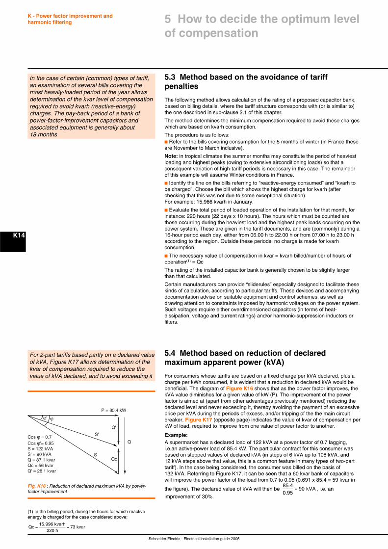
Schneider Electric - Electrical installation guide 2005
K - Power factor improvement andharmonic filtering
K14
5.3 Method based on the avoidance of tariffpenalties
The following method allows calculation of the rating of a proposed capacitor bank,based on billing details, where the tariff structure corresponds with (or is similar to)the one described in sub-clause 2.1 of this chapter.
The method determines the minimum compensation required to avoid these chargeswhich are based on kvarh consumption.
The procedure is as follows:c Refer to the bills covering consumption for the 5 months of winter (in France theseare November to March inclusive).
Note: in tropical climates the summer months may constitute the period of heaviestloading and highest peaks (owing to extensive airconditioning loads) so that aconsequent variation of high-tariff periods is necessary in this case. The remainderof this example will assume Winter conditions in France.
c Identify the line on the bills referring to “reactive-energy consumed” and “kvarh tobe charged”. Choose the bill which shows the highest charge for kvarh (afterchecking that this was not due to some exceptional situation).For example: 15,966 kvarh in January.
c Evaluate the total period of loaded operation of the installation for that month, forinstance: 220 hours (22 days x 10 hours). The hours which must be counted arethose occurring during the heaviest load and the highest peak loads occurring on thepower system. These are given in the tariff documents, and are (commonly) during a16-hour period each day, either from 06.00 h to 22.00 h or from 07.00 h to 23.00 haccording to the region. Outside these periods, no charge is made for kvarhconsumption.
c The necessary value of compensation in kvar = kvarh billed/number of hours ofoperation(1) = Qc
The rating of the installed capacitor bank is generally chosen to be slightly largerthan that calculated.
Certain manufacturers can provide “sliderules” especially designed to facilitate thesekinds of calculation, according to particular tariffs. These devices and accompanyingdocumentation advise on suitable equipment and control schemes, as well asdrawing attention to constraints imposed by harmonic voltages on the power system.Such voltages require either overdimensioned capacitors (in terms of heat-dissipation, voltage and current ratings) and/or harmonic-suppression inductors orfilters.
5.4 Method based on reduction of declaredmaximum apparent power (kVA)
For consumers whose tariffs are based on a fixed charge per kVA declared, plus acharge per kWh consumed, it is evident that a reduction in declared kVA would bebeneficial. The diagram of Figure K16 shows that as the power factor improves, thekVA value diminishes for a given value of kW (P). The improvement of the powerfactor is aimed at (apart from other advantages previously mentioned) reducing thedeclared level and never exceeding it, thereby avoiding the payment of an excessiveprice per kVA during the periods of excess, and/or tripping of the the main circuitbreaker. Figure K17 (opposite page) indicates the value of kvar of compensation perkW of load, required to improve from one value of power factor to another.
Example:A supermarket has a declared load of 122 kVA at a power factor of 0.7 lagging,i.e.an active-power load of 85.4 kW. The particular contract for this consumer wasbased on stepped values of declared kVA (in steps of 6 kVA up to 108 kVA, and12 kVA steps above that value, this is a common feature in many types of two-parttariff). In the case being considered, the consumer was billed on the basis of132 kVA. Referring to Figure K17, it can be seen that a 60 kvar bank of capacitorswill improve the power factor of the load from 0.7 to 0.95 (0.691 x 85.4 = 59 kvar in
the figure). The declared value of kVA will then be 85.40.95
9 kVA= 0 , i.e. an
improvement of 30%.
For 2-part tariffs based partly on a declared valueof kVA, Figure K17 allows determination of thekvar of compensation required to reduce thevalue of kVA declared, and to avoid exceeding it
Qc
ϕϕ'
P = 85.4 kW
Cos ϕ = 0.7 Cos ϕ'= 0.95S = 122 kVAS' = 90 kVAQ = 87.1 kvarQc = 56 kvarQ' = 28.1 kvar
S
S'
Q
Q'
Fig. K16 : Reduction of declared maximum kVA by power-factor improvement
5 How to decide the optimum levelof compensation
In the case of certain (common) types of tariff,an examination of several bills covering themost heavily-loaded period of the year allowsdetermination of the kvar level of compensationrequired to avoid kvarh (reactive-energy)charges. The pay-back period of a bank ofpower-factor-improvement capacitors andassociated equipment is generally about18 months
(1) In the billing period, during the hours for which reactiveenergy is charged for the case considered above:
Qc15,996 kvarh
220 h73 kvar= =
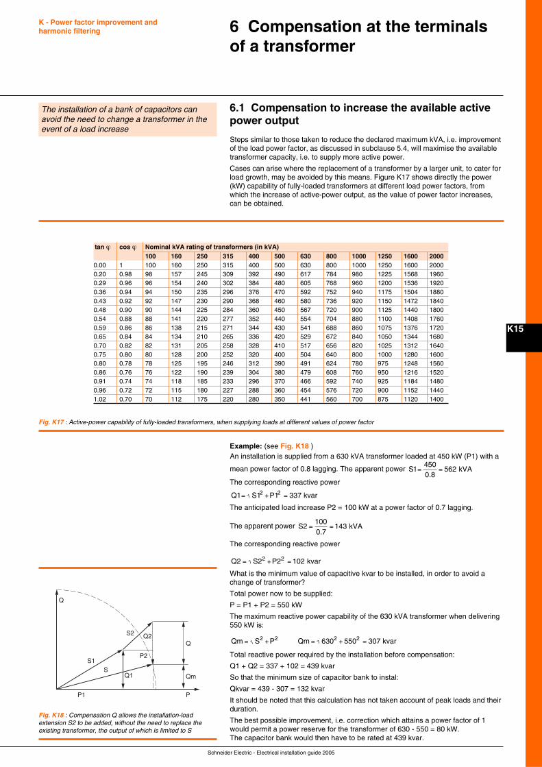
Schneider Electric - Electrical installation guide 2005
K15
6.1 Compensation to increase the available activepower output
Steps similar to those taken to reduce the declared maximum kVA, i.e. improvementof the load power factor, as discussed in subclause 5.4, will maximise the availabletransformer capacity, i.e. to supply more active power.
Cases can arise where the replacement of a transformer by a larger unit, to cater forload growth, may be avoided by this means. Figure K17 shows directly the power(kW) capability of fully-loaded transformers at different load power factors, fromwhich the increase of active-power output, as the value of power factor increases,can be obtained.
6 Compensation at the terminalsof a transformer
The installation of a bank of capacitors canavoid the need to change a transformer in theevent of a load increase
Example: (see Fig. K18 )An installation is supplied from a 630 kVA transformer loaded at 450 kW (P1) with a
mean power factor of 0.8 lagging. The apparent power S4500.8
5 kVA1 62= =
The corresponding reactive power
Q1 S1 P1 337 kvar2 2= + =
The anticipated load increase P2 = 100 kW at a power factor of 0.7 lagging.
The apparent power S1000.7
kVA2 143= =
The corresponding reactive power
Q2 S2 P2 1 kvar2 2= + = 02
What is the minimum value of capacitive kvar to be installed, in order to avoid achange of transformer?
Total power now to be supplied:
P = P1 + P2 = 550 kW
The maximum reactive power capability of the 630 kVA transformer when delivering550 kW is:
Qm S P2 2= + Qm 6 5 307 kvar2 2= + =30 50
Total reactive power required by the installation before compensation:
Q1 + Q2 = 337 + 102 = 439 kvar
So that the minimum size of capacitor bank to instal:
Qkvar = 439 - 307 = 132 kvar
It should be noted that this calculation has not taken account of peak loads and theirduration.
The best possible improvement, i.e. correction which attains a power factor of 1would permit a power reserve for the transformer of 630 - 550 = 80 kW.The capacitor bank would then have to be rated at 439 kvar.
Fig. K17 : Active-power capability of fully-loaded transformers, when supplying loads at different values of power factor
Q
Q
PP1
S1S
Q1
P2
S2 Q2
Qm
Fig. K18 : Compensation Q allows the installation-loadextension S2 to be added, without the need to replace theexisting transformer, the output of which is limited to S
K - Power factor improvement andharmonic filtering
tan ϕ cos ϕ Nominal kVA rating of transformers (in kVA)100 160 250 315 400 500 630 800 1000 1250 1600 2000
0.00 1 100 160 250 315 400 500 630 800 1000 1250 1600 20000.20 0.98 98 157 245 309 392 490 617 784 980 1225 1568 19600.29 0.96 96 154 240 302 384 480 605 768 960 1200 1536 19200.36 0.94 94 150 235 296 376 470 592 752 940 1175 1504 18800.43 0.92 92 147 230 290 368 460 580 736 920 1150 1472 18400.48 0.90 90 144 225 284 360 450 567 720 900 1125 1440 18000.54 0.88 88 141 220 277 352 440 554 704 880 1100 1408 17600.59 0.86 86 138 215 271 344 430 541 688 860 1075 1376 17200.65 0.84 84 134 210 265 336 420 529 672 840 1050 1344 16800.70 0.82 82 131 205 258 328 410 517 656 820 1025 1312 16400.75 0.80 80 128 200 252 320 400 504 640 800 1000 1280 16000.80 0.78 78 125 195 246 312 390 491 624 780 975 1248 15600.86 0.76 76 122 190 239 304 380 479 608 760 950 1216 15200.91 0.74 74 118 185 233 296 370 466 592 740 925 1184 14800.96 0.72 72 115 180 227 288 360 454 576 720 900 1152 14401.02 0.70 70 112 175 220 280 350 441 560 700 875 1120 1400

Schneider Electric - Electrical installation guide 2005
K - Power factor improvement andharmonic filtering
K16
6.2 Compensation of reactive energy absorbed bythe transformer
The nature of transformer inductive reactancesAll previous references have been to shuntconnected devices such as those used innormal loads, and power factor-correcting capacitor banks etc. The reason for this isthat shuntconnected plant requires (by far) the largest quantities of reactive energy inpower systems; however, series-connected reactances, such as the inductivereactances of power lines and the leakage reactance of transformer windings, etc.,also absorb reactive energy.
Where metering is carried out at the HV side of a transformer, the reactive-energylosses in the transformer may (depending on the tariff) need to be compensated. Asfar as reactive-energy losses only are concerned, a transformer may be representedby the elementary diagram of Figure K19 . All reactance values are referred to thesecondary side of the transformer, where the shunt branch represents themagnetizing-current path. The magnetizing current remains practically constant (atabout 1.8% of full-load current) from no load to full load, in normal circumstances, i.e.with a constant primary voltage, so that a shunt capacitor of fixed value can beinstalled at the HV or LV side, to compensate for the reactive energy absorbed.
XL reactive-power absorption in series-connected(leakage flux) reactance
A simple illustration of this phenomenon is given by the vector diagram ofFigure K20 .
The reactive-current component through the load = I sin ϕ so that kvarL = VI sin ϕ.
The reactive-current component from the source = I sin ϕ’ so that
kvars = EI sin ϕ’
where V and E are expressed in kV.
It can be seen that E > V and sin ϕ’ > sin ϕ.
The difference between EI sin ϕ’ and VI sin ϕ gives the kvar per phase absorbedby XL.
It can be shown that this kvar value is equal to I2XL (which is analogous to the I2Ractivepower (kW) losses due to the series resistance of power lines, etc.).
From the I2XL formula it is very simple to deduce the kvar absorbed at any loadvalue for a given transformer, as follows:
If per-unit values are used (instead of percentage values) direct multiplication of Iand XL can be carried out.
Example:A 630 kVA transformer with a short-circuit reactance voltage of 4% is fully loaded.
What is its reactive-power (kvar) loss?
4% = 0.04 pu Ipu = 1
loss = I2XL = 12 x 0.04 = 0.04 pu kvar
where 1 pu = 630 kVA
The 3-phase kvar losses are 630 x 0.04 = 25.2 kvar (or, quite simply, 4% of630 kVA).
At half load i.e. I = 0.5 pu the losses will be0.52 x 0.04 = 0.01 pu = 630 x 0.01 = 6.3 kvar and so on...
This example, and the vector diagram of Figure K22 show that:c The power factor at the primary side of a loaded transformer is different (normallylower) than that at the secondary side (due to the absorption of vars)c That full-load kvar losses due to leakage reactance are equal to the transformerpercentage reactance (4% reactance means a kvar loss equal to 4% of the kVA ratingof the transformer)c That kvar losses due to leakage reactance vary according to the current(or kVA loading) squared
Where metering is carried out at the HV side ofa transformer, the reactive-energy losses in thetransformer may (depending on the tariff) needto be compensated
Fig. K19 : Transformer reactances per phase
Perfect transformer
Primarywinding
Secondarywinding
Magnetizingreactance
Leakage reactance
The reactive power absorbed by a transformercannot be neglected, and can amount to (about)5% of the transformer rating when supplying itsfull load. Compensation can be provided by abank of capacitors. In transformers, reactivepower is absorbed by both shunt (magnetizing)and series (leakage flux) reactances. Completecompensation can be provided by a bank ofshunt-connected LV capacitors
XL
ESource
VLoad
E
ϕϕ'
I sin ϕ
I
I sin
I
ϕ'
VIXL
Fig. K20 : Reactive power absorption by series inductance
6 Compensation at the terminalsof a transformer
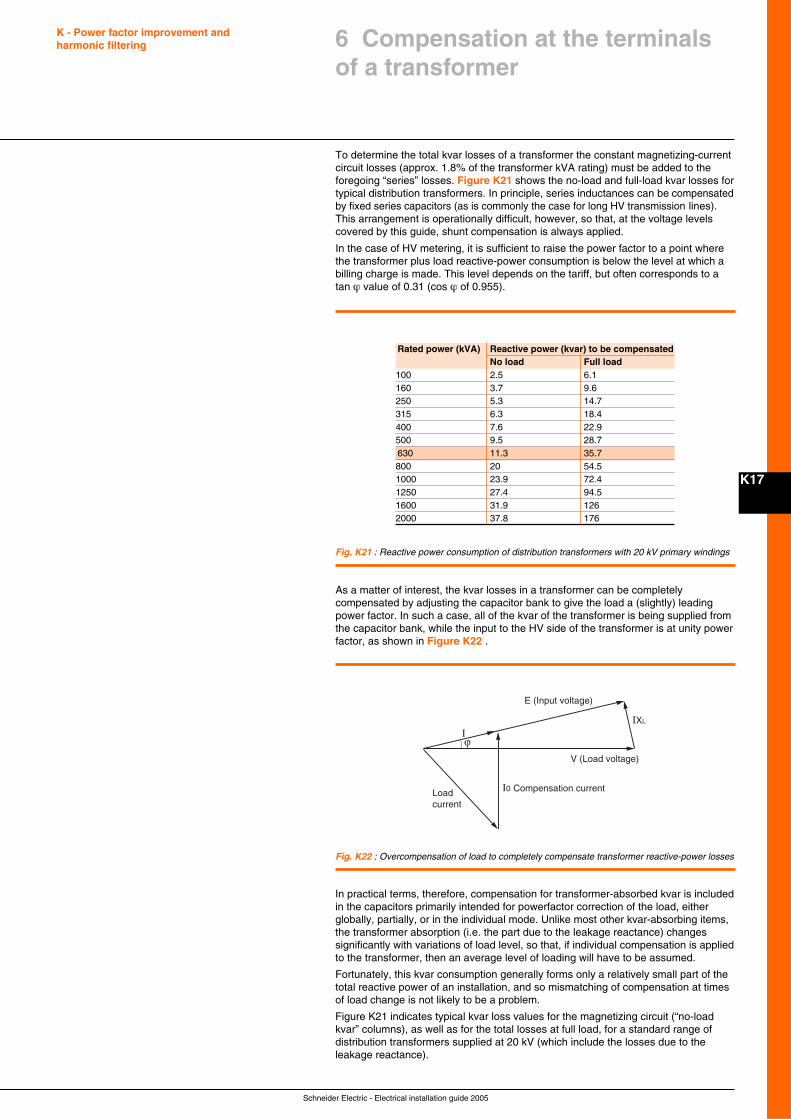
Schneider Electric - Electrical installation guide 2005
K - Power factor improvement andharmonic filtering
K17
To determine the total kvar losses of a transformer the constant magnetizing-currentcircuit losses (approx. 1.8% of the transformer kVA rating) must be added to theforegoing “series” losses. Figure K21 shows the no-load and full-load kvar losses fortypical distribution transformers. In principle, series inductances can be compensatedby fixed series capacitors (as is commonly the case for long HV transmission lines).This arrangement is operationally difficult, however, so that, at the voltage levelscovered by this guide, shunt compensation is always applied.
In the case of HV metering, it is sufficient to raise the power factor to a point wherethe transformer plus load reactive-power consumption is below the level at which abilling charge is made. This level depends on the tariff, but often corresponds to atan ϕ value of 0.31 (cos ϕ of 0.955).
6 Compensation at the terminalsof a transformer
Rated power (kVA) Reactive power (kvar) to be compensatedNo load Full load
100 2.5 6.1160 3.7 9.6250 5.3 14.7315 6.3 18.4400 7.6 22.9500 9.5 28.7630 11.3 35.7800 20 54.51000 23.9 72.41250 27.4 94.51600 31.9 1262000 37.8 176
Fig. K21 : Reactive power consumption of distribution transformers with 20 kV primary windings
ϕ
IXL
I
V (Load voltage)
E (Input voltage)
Load current
I0 Compensation current
Fig. K22 : Overcompensation of load to completely compensate transformer reactive-power losses
As a matter of interest, the kvar losses in a transformer can be completelycompensated by adjusting the capacitor bank to give the load a (slightly) leadingpower factor. In such a case, all of the kvar of the transformer is being supplied fromthe capacitor bank, while the input to the HV side of the transformer is at unity powerfactor, as shown in Figure K22 .
In practical terms, therefore, compensation for transformer-absorbed kvar is includedin the capacitors primarily intended for powerfactor correction of the load, eitherglobally, partially, or in the individual mode. Unlike most other kvar-absorbing items,the transformer absorption (i.e. the part due to the leakage reactance) changessignificantly with variations of load level, so that, if individual compensation is appliedto the transformer, then an average level of loading will have to be assumed.
Fortunately, this kvar consumption generally forms only a relatively small part of thetotal reactive power of an installation, and so mismatching of compensation at timesof load change is not likely to be a problem.
Figure K21 indicates typical kvar loss values for the magnetizing circuit (“no-loadkvar” columns), as well as for the total losses at full load, for a standard range ofdistribution transformers supplied at 20 kV (which include the losses due to theleakage reactance).
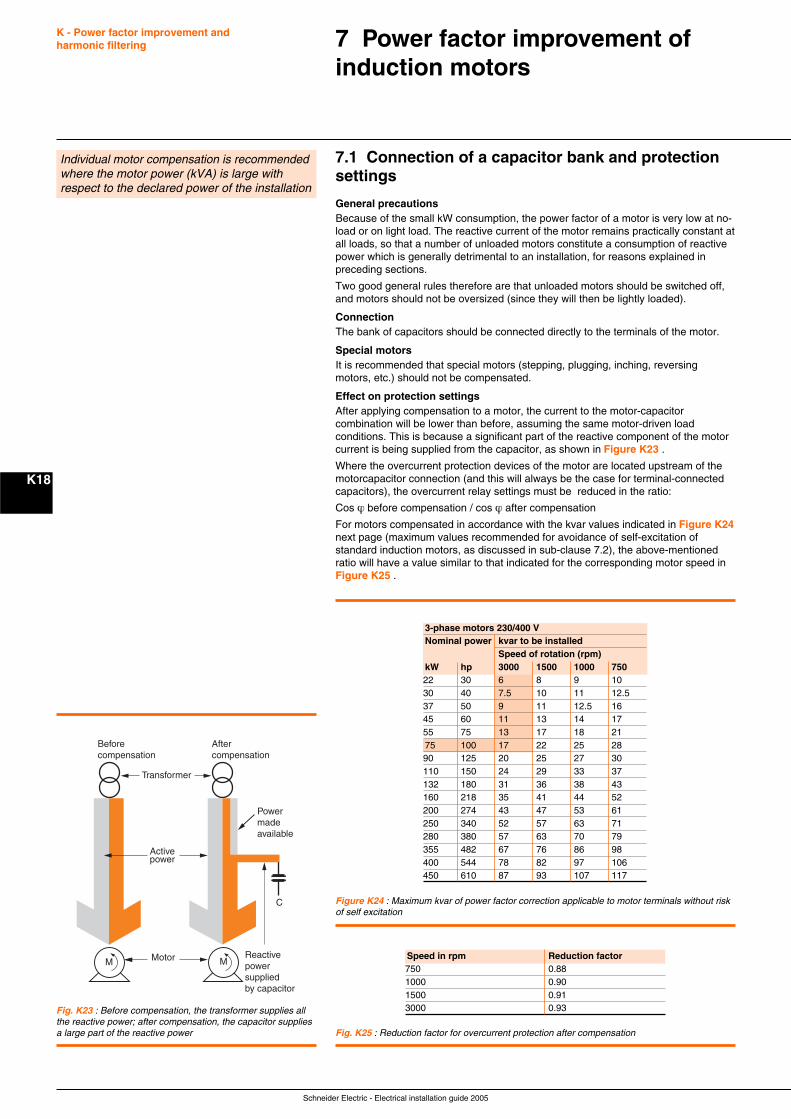
Schneider Electric - Electrical installation guide 2005
K - Power factor improvement andharmonic filtering
K18
7.1 Connection of a capacitor bank and protectionsettings
General precautionsBecause of the small kW consumption, the power factor of a motor is very low at no-load or on light load. The reactive current of the motor remains practically constant atall loads, so that a number of unloaded motors constitute a consumption of reactivepower which is generally detrimental to an installation, for reasons explained inpreceding sections.
Two good general rules therefore are that unloaded motors should be switched off,and motors should not be oversized (since they will then be lightly loaded).
ConnectionThe bank of capacitors should be connected directly to the terminals of the motor.
Special motorsIt is recommended that special motors (stepping, plugging, inching, reversingmotors, etc.) should not be compensated.
Effect on protection settingsAfter applying compensation to a motor, the current to the motor-capacitorcombination will be lower than before, assuming the same motor-driven loadconditions. This is because a significant part of the reactive component of the motorcurrent is being supplied from the capacitor, as shown in Figure K23 .
Where the overcurrent protection devices of the motor are located upstream of themotorcapacitor connection (and this will always be the case for terminal-connectedcapacitors), the overcurrent relay settings must be reduced in the ratio:
Cos ϕ before compensation / cos ϕ after compensation
For motors compensated in accordance with the kvar values indicated in Figure K24next page (maximum values recommended for avoidance of self-excitation ofstandard induction motors, as discussed in sub-clause 7.2), the above-mentionedratio will have a value similar to that indicated for the corresponding motor speed inFigure K25 .
7 Power factor improvement ofinduction motors
Individual motor compensation is recommendedwhere the motor power (kVA) is large withrespect to the declared power of the installation
Speed in rpm Reduction factor750 0.881000 0.901500 0.913000 0.93
Activepower
Reactive power supplied by capacitor
Power made available
C
Transformer
Before compensation
After compensation
MotorM M
Fig. K23 : Before compensation, the transformer supplies allthe reactive power; after compensation, the capacitor suppliesa large part of the reactive power Fig. K25 : Reduction factor for overcurrent protection after compensation
3-phase motors 230/400 VNominal power kvar to be installed
Speed of rotation (rpm)kW hp 3000 1500 1000 75022 30 6 8 9 1030 40 7.5 10 11 12.537 50 9 11 12.5 1645 60 11 13 14 1755 75 13 17 18 2175 100 17 22 25 2890 125 20 25 27 30110 150 24 29 33 37132 180 31 36 38 43160 218 35 41 44 52200 274 43 47 53 61250 340 52 57 63 71280 380 57 63 70 79355 482 67 76 86 98400 544 78 82 97 106450 610 87 93 107 117
Figure K24 : Maximum kvar of power factor correction applicable to motor terminals without riskof self excitation
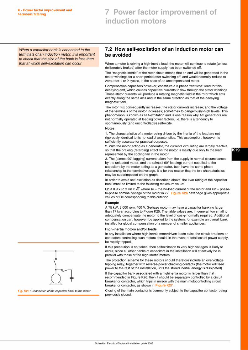
Schneider Electric - Electrical installation guide 2005
K - Power factor improvement andharmonic filtering
K19
7.2 How self-excitation of an induction motor canbe avoided
When a motor is driving a high-inertia load, the motor will continue to rotate (unlessdeliberately braked) after the motor supply has been switched off.
The “magnetic inertia” of the rotor circuit means that an emf will be generated in thestator windings for a short period after switching off, and would normally reduce tozero after 1 or 2 cycles, in the case of an uncompensated motor.
Compensation capacitors however, constitute a 3-phase “wattless” load for thisdecaying emf, which causes capacitive currents to flow through the stator windings.These stator currents will produce a rotating magnetic field in the rotor which actsexactly along the same axis and in the same direction as that of the decayingmagnetic field.
The rotor flux consequently increases; the stator currents increase; and the voltageat the terminals of the motor increases; sometimes to dangerously-high levels. Thisphenomenon is known as self-excitation and is one reason why AC generators arenot normally operated at leading power factors, i.e. there is a tendency tospontaneously (and uncontrollably) selfexcite.
Notes:
1. The characteristics of a motor being driven by the inertia of the load are notrigorously identical to its no-load characteristics. This assumption, however, issufficiently accurate for practical purposes.2. With the motor acting as a generator, the currents circulating are largely reactive,so that the braking (retarding) effect on the motor is mainly due only to the loadrepresented by the cooling fan in the motor.3. The (almost 90° lagging) current taken from the supply in normal circumstancesby the unloaded motor, and the (almost 90° leading) current supplied to thecapacitors by the motor acting as a generator, both have the same phaserelationship to the terminalvoltage. It is for this reason that the two characteristicsmay be superimposed on the graph.
In order to avoid self-excitation as described above, the kvar rating of the capacitorbank must be limited to the following maximum value:
Qc i 0.9 x Io x Un x e where Io = the no-load current of the motor and Un = phase-to-phase nominal voltage of the motor in kV. Figure K26 next page gives appropriatevalues of Qc corresponding to this criterion.
ExampleA 75 kW, 3,000 rpm, 400 V, 3-phase motor may have a capacitor bank no largerthan 17 kvar according to Figure K25. The table values are, in general, too small toadequately compensate the motor to the level of cos ϕ normally required. Additionalcompensation can, however, be applied to the system, for example an overall bank,installed for global compensation of a number of smaller appliances.
High-inertia motors and/or loadsIn any installation where high-inertia motordriven loads exist, the circuit breakers orcontactors controlling such motors should, in the event of total loss of power supply,be rapidly tripped.
If this precaution is not taken, then selfexcitation to very high voltages is likely tooccur, since all other banks of capacitors in the installation will effectively be inparallel with those of the high-inertia motors.
The protection scheme for these motors should therefore include an overvoltagetripping relay, together with reverse-power checking contacts (the motor will feedpower to the rest of the installation, until the stored inertial energy is dissipated).
If the capacitor bank associated with a highinertia motor is larger than thatrecommended in Figure K26, then it should be separately controlled by a circuitbreaker or contactor, which trips in unison with the main motocontrolling circuitbreaker or contactor, as shown in Figure K27 .
Closing of the main contactor is commonly subject to the capacitor contactor beingpreviously closed.
When a capacitor bank is connected to theterminals of an induction motor, it is importantto check that the size of the bank is less thanthat at which self-excitation can occur
Fig. K27 : Connection of the capacitor bank to the motor
7 Power factor improvement ofinduction motors
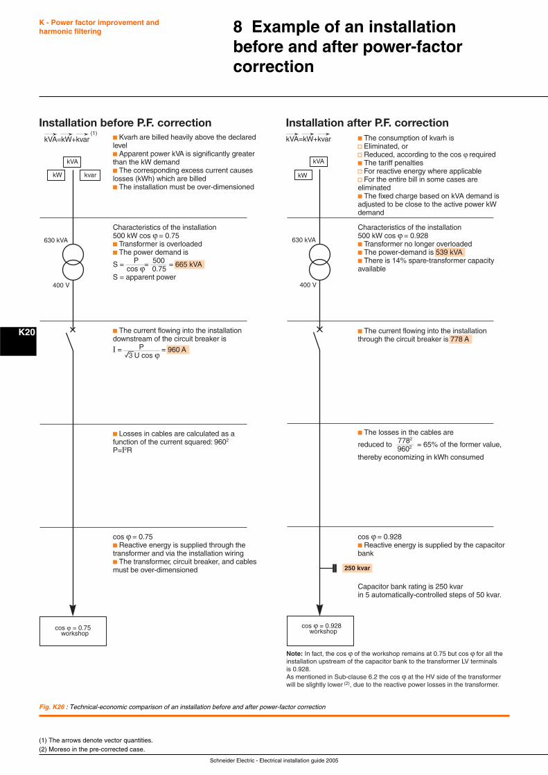
Schneider Electric - Electrical installation guide 2005
K20
K - Power factor improvement andharmonic filtering 8 Example of an installation
before and after power-factorcorrection
cos ϕ = 0.75workshop
kVA
kW kvar
630 kVA
400 V
Installation before P.F. correctionc Kvarh are billed heavily above the declaredlevelc Apparent power kVA is significantly greaterthan the kW demandc The corresponding excess current causeslosses (kWh) which are billedc The installation must be over-dimensioned
kVA=kW+kvar→→→ →→→
Characteristics of the installation500 kW cos ϕ = 0.75c Transformer is overloadedc The power demand is
S = P = 500 = 665 kVA cos ϕ 0.75S = apparent power
c The current flowing into the installationdownstream of the circuit breaker is
I = P = 960 A eU cos ϕ
c Losses in cables are calculated as afunction of the current squared: 9602
P=I2R
cos ϕ = 0.75c Reactive energy is supplied through thetransformer and via the installation wiringc The transformer, circuit breaker, and cablesmust be over-dimensioned
Installation after P.F. correctionkVA=kW+kvar c The consumption of kvarh is
v Eliminated, orv Reduced, according to the cos ϕ requiredc The tariff penaltiesv For reactive energy where applicablev For the entire bill in some cases areeliminatedc The fixed charge based on kVA demand isadjusted to be close to the active power kWdemand
cos ϕ
Note: In fact, the cos ϕ of the workshop remains at 0.75 but cos ϕ for all theinstallation upstream of the capacitor bank to the transformer LV terminalsis 0.928.As mentioned in Sub-clause 6.2 the cos ϕ at the HV side of the transformerwill be slightly lower (2), due to the reactive power losses in the transformer.
= 0.928workshop
kVA
kW
630 kVA
400 V
250 kvar
Characteristics of the installation500 kW cos ϕ = 0.928c Transformer no longer overloadedc The power-demand is 539 kVAc There is 14% spare-transformer capacityavailable
c The current flowing into the installationthrough the circuit breaker is 778 A
c The losses in the cables are
reduced to 7782 = 65% of the former value, 9602
thereby economizing in kWh consumed
cos ϕ = 0.928c Reactive energy is supplied by the capacitor bank
Capacitor bank rating is 250 kvarin 5 automatically-controlled steps of 50 kvar.
(1)
Fig. K26 : Technical-economic comparison of an installation before and after power-factor correction
(1) The arrows denote vector quantities.(2) Moreso in the pre-corrected case.
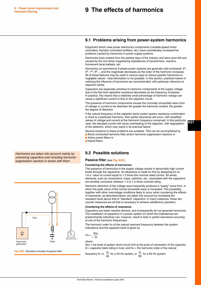
Schneider Electric - Electrical installation guide 2005
K21
9.1 Problems arising from power-system harmonics
Equipment which uses power electronics components (variable-speed motorcontrollers, thyristor-controlled rectifiers, etc.) have considerably increased theproblems caused by harmonics in power supply systems.
Harmonics have existed from the earliest days of the industry and were (and still are)caused by the non-linear magnetizing impedances of transformers, reactors,fluorescent lamp ballasts, etc.
Harmonics on symmetrical 3-phase power systems are generally odd-numbered: 3rd,5th, 7th, 9th..., and the magnitude decreases as the order of the harmonic increases.All of these features may be used in various ways to reduce specific harmonics tonegligible values - total elimination is not possible. In this section, practical means ofreducing the influence of harmonics are recommended, with particular reference tocapacitor banks.
Capacitors are especially sensitive to harmonic components of the supply voltagedue to the fact that capacitive reactance decreases as the frequency increases.In practice, this means that a relatively small percentage of harmonic voltage cancause a significant current to flow in the capacitor circuit.
The presence of harmonic components causes the (normally sinusoidal) wave formof voltage or current to be distorted; the greater the harmonic content, the greaterthe degree of distortion.
If the natural frequency of the capacitor bank/ power-system reactance combinationis close to a particular harmonic, then partial resonance will occur, with amplifiedvalues of voltage and current at the harmonic frequency concerned. In this particularcase, the elevated current will cause overheating of the capacitor, with degradationof the dielectric, which may result in its eventual failure.
Several solutions to these problems are available. This can be accomplished byc Shunt connected harmonic filter and/or harmonic-suppression reactors orc Active power filters orc Hybrid filters
9.2 Possible solutions
Passive filter (see Fig. K28 )
Countering the effects of harmonicsThe presence of harmonics in the supply voltage results in abnormally high currentlevels through the capacitors. An allowance is made for this by designing for anr.m.s. value of current equal to 1.3 times the nominal rated current. All serieselements, such as connections, fuses, switches, etc., associated with the capacitorsare similarly oversized, between 1.3 to 1.5 times nominal rating.
Harmonic distortion of the voltage wave frequently produces a “peaky” wave form, inwhich the peak value of the normal sinusoidal wave is increased. This possibility,together with other overvoltage conditions likely to occur when countering the effectsof resonance, as described below, are taken into account by increasing theinsulation level above that of “standard” capacitors. In many instances, these twocounter measures are all that is necessary to achieve satisfactory operation.
Countering the effects of resonanceCapacitors are linear reactive devices, and consequently do not generate harmonics.The installation of capacitors in a power system (in which the impedances arepredominantly inductive) can, however, result in total or partial resonance occurringat one of the harmonic frequencies.
The harmonic order ho of the natural resonant frequency between the systeminductance and the capacitor bank is given by
ho =SscQ
whereSsc = the level of system short-circuit kVA at the point of connection of the capacitorQ = capacitor bank rating in kvar; and ho = the harmonic order of the natural
frequency fo i.e. fo50
for a 50 Hz system, or fo60
for a 60 Hz system.
9 The effects of harmonicsK - Power factor improvement andharmonic filtering
Harmonics are taken into account mainly byoversizing capacitors and including harmonic-suppression reactors in series with them
Harmonic generator
Ihar
Filter
Fig. K28 : Operation principle of passive filter
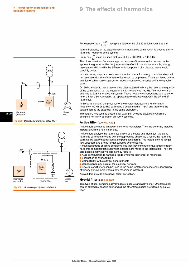
Schneider Electric - Electrical installation guide 2005
K - Power factor improvement andharmonic filtering
K22
For example: ho =SscQ
may give a value for ho of 2.93 which shows that the
natural frequency of the capacitor/system-inductance combination is close to the 3rd
harmonic frequency of the system.
From hofo50
= it can be seen that fo = 50 ho = 50 x 2.93 = 146.5 Hz
The closer a natural frequency approaches one of the harmonics present on thesystem, the greater will be the (undesirable) effect. In the above example, strongresonant conditions with the 3rd harmonic component of a distorted wave wouldcertainly occur.
In such cases, steps are taken to change the natural frequency to a value which willnot resonate with any of the harmonics known to be present. This is achieved by theaddition of a harmonic-suppression inductor connected in series with the capacitorbank.
On 50 Hz systems, these reactors are often adjusted to bring the resonant frequencyof the combination, i.e. the capacitor bank + reactors to 190 Hz. The reactors areadjusted to 228 Hz for a 60 Hz system. These frequencies correspond to a value forho of 3.8 for a 50 Hz system, i.e. approximately mid-way between the 3rd and 5th
harmonics.
In this arrangement, the presence of the reactor increases the fundamental-frequency (50 Hz or 60 Hz) current by a small amount (7-8%) and therefore thevoltage across the capacitor in the same proportion.
This feature is taken into account, for example, by using capacitors which aredesigned for 440 V operation on 400 V systems.
Active filter (see Fig. K29 )
Active filters are based on power electronic technology. They are generally installedin parallel with the non linear load.
Active filters analyse the harmonics drawn by the load and then inject the sameharmonic current to the load with the appropriate phase. As a result, the harmoniccurrents are totally neutralised at the point considered. This means they no longerflow upstream and are no longer supplied by the source.A main advantage of active conditioners is that they continue to guarantee efficientharmonic compensation even when changes are made to the installation. They arealso exceptionally easy to use as they feature:c Auto-configuration to harmonic loads whatever their order of magnitudec Elimination of overload risksc Compatibility with electrical generator setsc Connection to any point of the electrical networkc Several conditioners can be used in the same installation to increase depollutionefficiency (for example when a new machine is installed)
Active filters provide also power factor correction.
Hybrid filter (see Fig. K30 )
This type of filter combines advantages of passive and active filter. One frequencycan be filtered by passive filter and all the other frequencies are filtered by activefilter.
Fig. K30 : Operation principle of hybrid filter
Fig. K29 : Operation principle of active filter
Harmonic generator
Linear load
Active filter
IsIhar
Iact
Harmonic generator
Linear load
Active filter
IsIhar
Iact
Hybride filter
9 The effects of harmonics
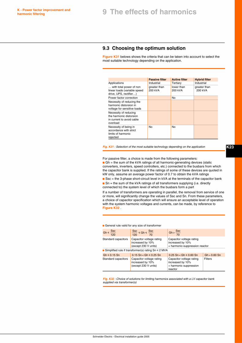
Schneider Electric - Electrical installation guide 2005
K - Power factor improvement andharmonic filtering
K23
9.3 Choosing the optimum solution
Figure K31 belows shows the criteria that can be taken into account to select themost suitable technology depending on the application.
Fig. K31 : Selection of the most suitable technology depending on the application
For passive filter, a choice is made from the following parameters:c Gh = the sum of the kVA ratings of all harmonic-generating devices (staticconverters, inverters, speed controllers, etc.) connected to the busbars from whichthe capacitor bank is supplied. If the ratings of some of these devices are quoted inkW only, assume an average power factor of 0.7 to obtain the kVA ratingsc Ssc = the 3-phase short-circuit level in kVA at the terminals of the capacitor bankc Sn = the sum of the kVA ratings of all transformers supplying (i.e. directlyconnected to) the system level of which the busbars form a part
If a number of transformers are operating in parallel, the removal from service of oneor more, will significantly change the values of Ssc and Sn. From these parameters,a choice of capacitor specification which will ensure an acceptable level of operationwith the system harmonic voltages and currents, can be made, by reference toFigure K32 .
Fig. K32 : Choice of solutions for limiting harmonics associated with a LV capacitor banksupplied via transformer(s)
c General rule valid for any size of transformer
Gh
Ssc120
i
i iSsc120
Gh Ssc70
Gh >Ssc70
Standard capacitors Capacitor voltage rating Capacitor voltage ratingincreased by 10% increased by 10%(except 230 V units) + harmonic-suppression reactor
c Simplified rule if transformer(s) rating Sn i 2 MVA
Gh 0.15 Sni 0.15 Sn < Gh 0.25 Sni 0.25 Sn < Gh 0.60 Sni Gh 0.60 Sn>Standard capacitors Capacitor voltage rating Capacitor voltage rating Filters
increased by 10% increased by 10%(except 230 V units) + harmonic suppression
reactor
9 The effects of harmonics
Passive filter Active filter Hybrid filterApplications Industrial Tertiary Industrial… with total power of non greater than lower than greater thanlinear loads (variable speed 200 kVA 200 kVA 200 kVAdrive, UPS, rectifier…)Power factor correction NoNecessity of reducing theharmonic distorsion involtage for sensitive loadsNecessity of reducingthe harmonic distorsionin current to avoid cableoverloadNecessity of being in No Noaccordance with strictlimits of harmonicrejected
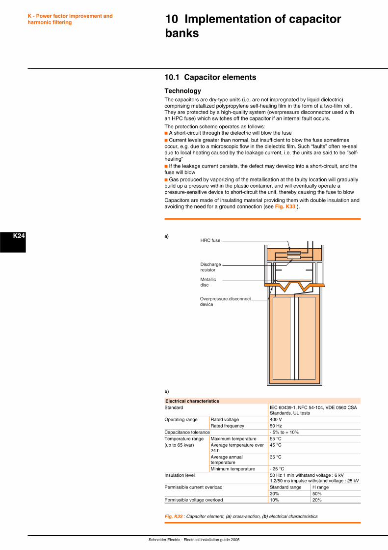
Schneider Electric - Electrical installation guide 2005
K - Power factor improvement andharmonic filtering
K24
10.1 Capacitor elements
TechnologyThe capacitors are dry-type units (i.e. are not impregnated by liquid dielectric)comprising metallized polypropylene self-healing film in the form of a two-film roll.They are protected by a high-quality system (overpressure disconnector used withan HPC fuse) which switches off the capacitor if an internal fault occurs.
The protection scheme operates as follows:c A short-circuit through the dielectric will blow the fusec Current levels greater than normal, but insufficient to blow the fuse sometimesoccur, e.g. due to a microscopic flow in the dielectric film. Such “faults” often re-sealdue to local heating caused by the leakage current, i.e. the units are said to be “self-healing”c If the leakage current persists, the defect may develop into a short-circuit, and thefuse will blowc Gas produced by vaporizing of the metallisation at the faulty location will graduallybuild up a pressure within the plastic container, and will eventually operate apressure-sensitive device to short-circuit the unit, thereby causing the fuse to blow
Capacitors are made of insulating material providing them with double insulation andavoiding the need for a ground connection (see Fig. K33 ).
10 Implementation of capacitorbanks
Fig. K33 : Capacitor element, (a) cross-section, (b) electrical characteristics
Electrical characteristicsStandard IEC 60439-1, NFC 54-104, VDE 0560 CSA
Standards, UL testsOperating range Rated voltage 400 V
Rated frequency 50 HzCapacitance tolerance - 5% to + 10%Temperature range Maximum temperature 55 °C(up to 65 kvar) Average temperature over 45 °C
24 hAverage annual 35 °CtemperatureMinimum temperature - 25 °C
Insulation level 50 Hz 1 min withstand voltage : 6 kV1.2/50 ms impulse withstand voltage : 25 kV
Permissible current overload Standard range H range30% 50%
Permissible voltage overload 10% 20%
HRC fuse
Dischargeresistor
Metallicdisc
Overpressure disconnectdevice
a)
b)
Schneider Electric - Electrical installation guide 2005
K - Power factor improvement andharmonic filtering
K25
10.2 Choice of protection, control devices andconnecting cables
The choice of upstream cables and protection and control devices depends on thecurrent loading.
For capacitors, the current is a function of:c The applied voltage and its harmonicsc The capacitance value
The nominal current In a capacitor of kvar rating Q, supplied from a 3-phase systemhaving a phase/phase voltage of Un kilo-volts, is given by:
InUn 3
=Q
The permitted range of applied voltage at fundamental frequency, plus harmoniccomponents, together with manufacturing tolerances of actual capacitance (for adeclared nominal value) can result in a 50% increase above the calculated value ofcurrent. Approximately 30% of this increase is due to the voltage increases, while afurther 15% is due to the range of manufacturing tolerances, so that1.3 x 1.15 = 1.5 In.
All components carrying the capacitor current therefore, must be adequate to coverthis “worst-case” condition, in an ambient temperature of 50 °C maximum. In thecase where higher temperatures (than 50 °C) occur in enclosures, etc. derating ofthe components will be necessary.
Protection
The size of the circuit breaker can be chosen in order to allow the setting of longtime delay at:
c 1.36 x In for standard type
c 1.50 x In for H type
c 1.12 x In for SAH type (tuned at 2.7 f)
c 1.19 x In for SAH type (tuned at 3.8 f)
c 1.31 x In for SAH type (tuned at 4.3 f)
Short time delay setting (short-circuit protection) must be insensitive to inrushcurrent. The setting will be 10 x In for standard type, H type and SAH type.
Example 1
50 kvar – 400V – 50 Hz – standard type
In400 x 1.732
72 A=( )
=50 000,
Long time delay setting: 1.36 x 72 = 98 A
Short time delay setting: 10 x In = 720 A
Example 2
50 kvar – 400V – 50 Hz – SAH type (tuned at 4.3 f)
In = 72 A
Long time delay setting: 1.31 x 72 = 94 A
Short time delay setting: 10 x In = 720 A
Upstream cablesFigure K34 next page gives the minimum cross section area of the upstream cablefor Rectiphase capacitors.
Cables for controlThe minimum cross section area of these cables will be 1.5 mm2 for 230 V.
For the secondary side of the transformer, the recommended cross sectionarea is u 2.5 mm2.
10 Implementation of capacitorbanks
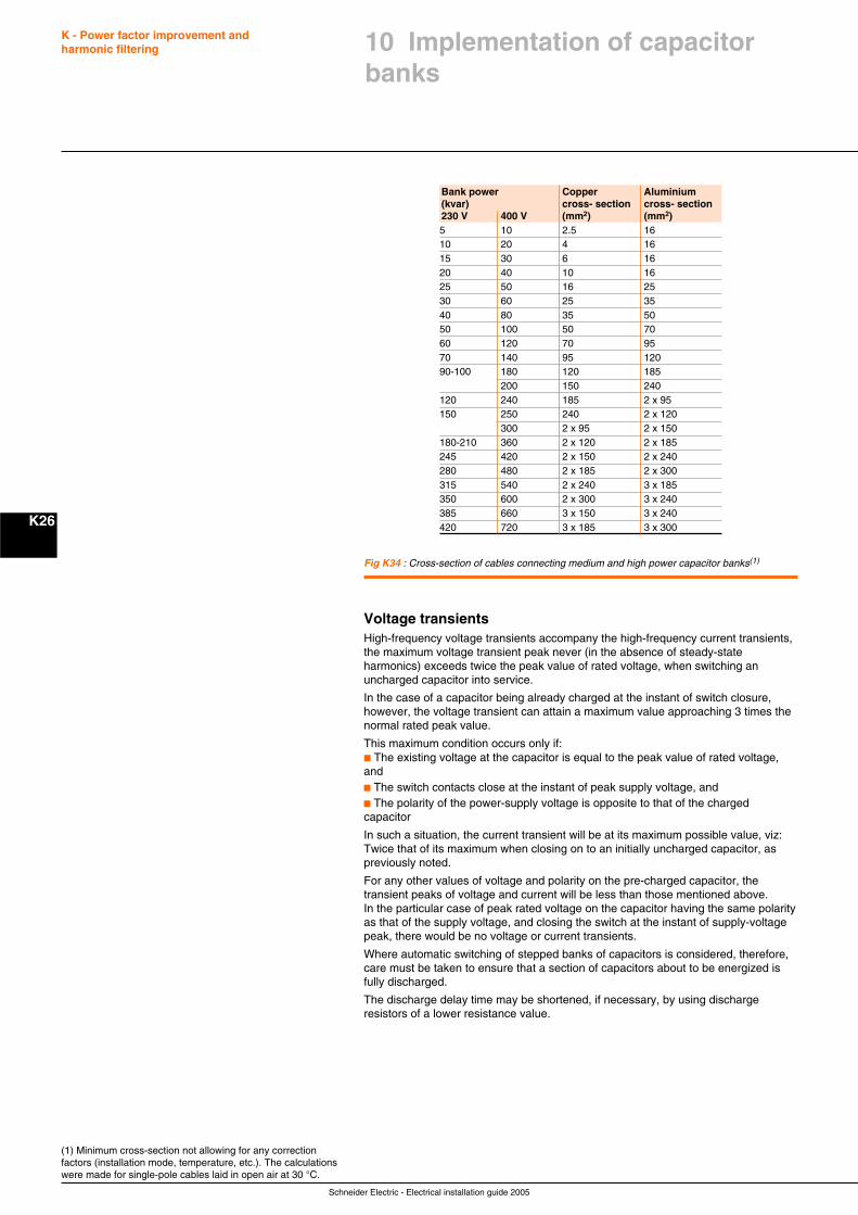
Schneider Electric - Electrical installation guide 2005
K - Power factor improvement andharmonic filtering
K26
10 Implementation of capacitorbanks
Fig K34 : Cross-section of cables connecting medium and high power capacitor banks(1)
(1) Minimum cross-section not allowing for any correctionfactors (installation mode, temperature, etc.). The calculationswere made for single-pole cables laid in open air at 30 °C.
Bank power Copper Aluminium(kvar) cross- section cross- section230 V 400 V (mm2) (mm2)5 10 2.5 1610 20 4 1615 30 6 1620 40 10 1625 50 16 2530 60 25 3540 80 35 5050 100 50 7060 120 70 9570 140 95 12090-100 180 120 185
200 150 240120 240 185 2 x 95150 250 240 2 x 120
300 2 x 95 2 x 150180-210 360 2 x 120 2 x 185245 420 2 x 150 2 x 240280 480 2 x 185 2 x 300315 540 2 x 240 3 x 185350 600 2 x 300 3 x 240385 660 3 x 150 3 x 240420 720 3 x 185 3 x 300
Voltage transientsHigh-frequency voltage transients accompany the high-frequency current transients,the maximum voltage transient peak never (in the absence of steady-stateharmonics) exceeds twice the peak value of rated voltage, when switching anuncharged capacitor into service.
In the case of a capacitor being already charged at the instant of switch closure,however, the voltage transient can attain a maximum value approaching 3 times thenormal rated peak value.
This maximum condition occurs only if:c The existing voltage at the capacitor is equal to the peak value of rated voltage,andc The switch contacts close at the instant of peak supply voltage, andc The polarity of the power-supply voltage is opposite to that of the chargedcapacitor
In such a situation, the current transient will be at its maximum possible value, viz:Twice that of its maximum when closing on to an initially uncharged capacitor, aspreviously noted.
For any other values of voltage and polarity on the pre-charged capacitor, thetransient peaks of voltage and current will be less than those mentioned above.In the particular case of peak rated voltage on the capacitor having the same polarityas that of the supply voltage, and closing the switch at the instant of supply-voltagepeak, there would be no voltage or current transients.
Where automatic switching of stepped banks of capacitors is considered, therefore,care must be taken to ensure that a section of capacitors about to be energized isfully discharged.
The discharge delay time may be shortened, if necessary, by using dischargeresistors of a lower resistance value.
Schneider Electric - Electrical installation guide 2005
L1
Chapter LDetection and filtering ofharmonics
Contents
The problem: Why is it necessary to detect L2and eliminate harmonics?
Standards L3
General L4
Main effects of harmonics in installations L6
4.1 Resonance L6
4.2 Increased losses L6
4.3 Overloads on equipment L7
4.4 Disturbances affecting sensitive loads L9
4.5 Economic impact L10
Essential indicators of harmonic distortion L11and measurement principles
5.1 Power factor L11
5.2 Crest factor L11
5.3 Power values and harmonics L11
5.4 Harmonic spectrum and harmonic distortion L12
5.5 Total harmonic distortion (THD) L12
5.6 Usefulness of the various indicators L13
Measuring the indicators L14
6.1 Devices used to measure the indicators L14
6.2 Procedures for harmonic analysis of distribution networks L14
6.3 Keeping a close eye on harmonics L15
Detection devices L16
Solutions to attenuate harmonics L17
8.1 Basic solutions L17
8.2 Harmonic filtering L18
8.3 The method L20
8.4 Specific products L20
1234
7
5
6
8
Schneider Electric - Electrical installation guide 2005
L - Detection and filtering of harmonics
L2
1 The problem: Why is it necessaryto detect and eliminate harmonics?
Disturbances caused by harmonicsHarmonics flowing in distribution networks downgrade the quality of electrical power.This can have a number of negative effects:c Overloads on distribution networks due to the increase in rms currentc Overloads in neutral conductors due to the cumulative increase in third-orderharmonics created by single-phase loadsc Overloads, vibration and premature ageing of generators, transformers and motorsas well as increased transformer humc Overloads and premature ageing of power-factor correction capacitorsc Distortion of the supply voltage that can disturb sensitive loadsc Disturbances in communication networks and on telephone lines
Economic impact of disturbancesHarmonics have a major economic impact:c Premature ageing of equipment means it must be replaced sooner unlessoversized right from the startc Overloads on the distribution network can require higher subscribed power levelsand increase lossesc Distortion of current waveforms provokes nuisance tripping that can stopproduction
Increasingly serious consequencesOnly ten years ago, harmonics were not yet considered a real problem because theireffects on distribution networks were generally minor. However, the massiveintroduction of power electronics in equipment has made the phenomenon far moreserious in all sectors of economic activity.
In addition, the equipment causing the harmonics is often vital to the company ororganisation.
Which harmonics must be measured and eliminated?The most frequently encountered harmonics in three-phase distribution networks arethe odd orders. Harmonic amplitudes normally decrease as the frequency increases.Above order 50, harmonics are negligible and measurements are no longermeaningful. Sufficiently accurate measurements are obtained by measuringharmonics up to order 30.
Utilities monitor harmonic orders 3, 5, 7, 11 and 13. Generally speaking, harmonicconditioning of the lowest orders (up to 13) is sufficient. More comprehensiveconditioning takes into account harmonic orders up to 25.
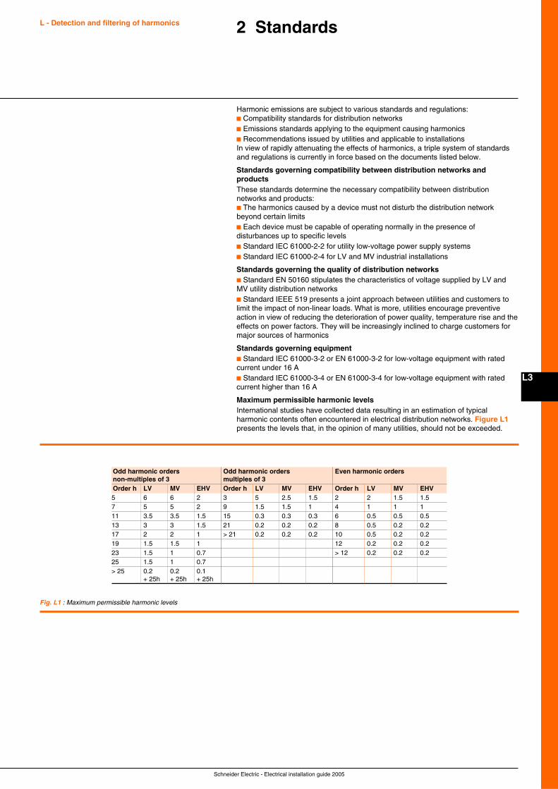
Schneider Electric - Electrical installation guide 2005
L3
2 Standards
Harmonic emissions are subject to various standards and regulations:c Compatibility standards for distribution networksc Emissions standards applying to the equipment causing harmonicsc Recommendations issued by utilities and applicable to installationsIn view of rapidly attenuating the effects of harmonics, a triple system of standardsand regulations is currently in force based on the documents listed below.
Standards governing compatibility between distribution networks andproductsThese standards determine the necessary compatibility between distributionnetworks and products:c The harmonics caused by a device must not disturb the distribution networkbeyond certain limitsc Each device must be capable of operating normally in the presence ofdisturbances up to specific levelsc Standard IEC 61000-2-2 for utility low-voltage power supply systemsc Standard IEC 61000-2-4 for LV and MV industrial installations
Standards governing the quality of distribution networksc Standard EN 50160 stipulates the characteristics of voltage supplied by LV andMV utility distribution networksc Standard IEEE 519 presents a joint approach between utilities and customers tolimit the impact of non-linear loads. What is more, utilities encourage preventiveaction in view of reducing the deterioration of power quality, temperature rise and theeffects on power factors. They will be increasingly inclined to charge customers formajor sources of harmonics
Standards governing equipmentc Standard IEC 61000-3-2 or EN 61000-3-2 for low-voltage equipment with ratedcurrent under 16 Ac Standard IEC 61000-3-4 or EN 61000-3-4 for low-voltage equipment with ratedcurrent higher than 16 A
Maximum permissible harmonic levelsInternational studies have collected data resulting in an estimation of typicalharmonic contents often encountered in electrical distribution networks. Figure L1presents the levels that, in the opinion of many utilities, should not be exceeded.
L - Detection and filtering of harmonics
Fig. L1 : Maximum permissible harmonic levels
Odd harmonic orders Odd harmonic orders Even harmonic ordersnon-multiples of 3 multiples of 3Order h LV MV EHV Order h LV MV EHV Order h LV MV EHV5 6 6 2 3 5 2.5 1.5 2 2 1.5 1.57 5 5 2 9 1.5 1.5 1 4 1 1 111 3.5 3.5 1.5 15 0.3 0.3 0.3 6 0.5 0.5 0.513 3 3 1.5 21 0.2 0.2 0.2 8 0.5 0.2 0.217 2 2 1 > 21 0.2 0.2 0.2 10 0.5 0.2 0.219 1.5 1.5 1 12 0.2 0.2 0.223 1.5 1 0.7 > 12 0.2 0.2 0.225 1.5 1 0.7> 25 0.2 0.2 0.1
+ 25h + 25h + 25h
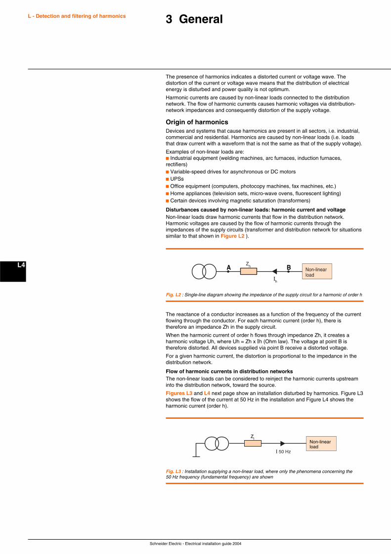
Schneider Electric - Electrical installation guide 2004
L4
L - Detection and filtering of harmonics
The presence of harmonics indicates a distorted current or voltage wave. Thedistortion of the current or voltage wave means that the distribution of electricalenergy is disturbed and power quality is not optimum.
Harmonic currents are caused by non-linear loads connected to the distributionnetwork. The flow of harmonic currents causes harmonic voltages via distribution-network impedances and consequently distortion of the supply voltage.
Origin of harmonicsDevices and systems that cause harmonics are present in all sectors, i.e. industrial,commercial and residential. Harmonics are caused by non-linear loads (i.e. loadsthat draw current with a waveform that is not the same as that of the supply voltage).
Examples of non-linear loads are:c Industrial equipment (welding machines, arc furnaces, induction furnaces,rectifiers)c Variable-speed drives for asynchronous or DC motorsc UPSsc Office equipment (computers, photocopy machines, fax machines, etc.)c Home appliances (television sets, micro-wave ovens, fluorescent lighting)c Certain devices involving magnetic saturation (transformers)
Disturbances caused by non-linear loads: harmonic current and voltageNon-linear loads draw harmonic currents that flow in the distribution network.Harmonic voltages are caused by the flow of harmonic currents through theimpedances of the supply circuits (transformer and distribution network for situationssimilar to that shown in Figure L2 ).
3 General
Non-linearload
AZh B
Ih
Fig. L2 : Single-line diagram showing the impedance of the supply circuit for a harmonic of order h
The reactance of a conductor increases as a function of the frequency of the currentflowing through the conductor. For each harmonic current (order h), there istherefore an impedance Zh in the supply circuit.
When the harmonic current of order h flows through impedance Zh, it creates aharmonic voltage Uh, where Uh = Zh x Ih (Ohm law). The voltage at point B istherefore distorted. All devices supplied via point B receive a distorted voltage.
For a given harmonic current, the distortion is proportional to the impedance in thedistribution network.
Flow of harmonic currents in distribution networksThe non-linear loads can be considered to reinject the harmonic currents upstreaminto the distribution network, toward the source.
Figures L3 and L4 next page show an installation disturbed by harmonics. Figure L3shows the flow of the current at 50 Hz in the installation and Figure L4 shows theharmonic current (order h).
Fig. L3 : Installation supplying a non-linear load, where only the phenomena concerning the50 Hz frequency (fundamental frequency) are shown
Non-linearload
Zl
I 50 Hz
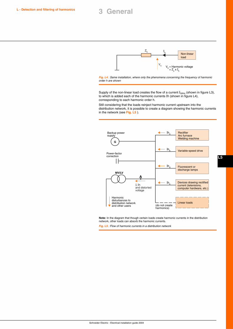
Schneider Electric - Electrical installation guide 2004
L5
L - Detection and filtering of harmonics
Fig. L4 : Same installation, where only the phenomena concerning the frequency of harmonicorder h are shown
Ih
Vh Vh = Harmonic voltage = Zs x Ih
ZhNon-linear load
Supply of the non-linear load creates the flow of a current I50Hz (shown in figure L3),to which is added each of the harmonic currents Ih (shown in figure L4),corresponding to each harmonic order h.
Still considering that the loads reinject harmonic current upstream into thedistribution network, it is possible to create a diagram showing the harmonic currentsin the network (see Fig. L5 ).
AMV/LV
Devices drawing rectified current (televisions, computer hardware, etc.)
Fluorescent or discharge lamps
Variable-speed drive
RectifierArc furnaceWelding machine
Linear loads
G
Backup power supply
Power-factor correction
Ihe
Ihd
Ihb
Iha
(do not create harmonics)
Harmonic disturbances to distribution network and other users
Fig. L5 : Flow of harmonic currents in a distribution network
Note: In the diagram that though certain loads create harmonic currents in the distributionnetwork, other loads can absorb the harmonic currents.
3 General
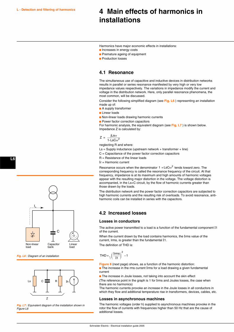
Schneider Electric - Electrical installation guide 2005
L - Detection and filtering of harmonics
L6
Harmonics have major economic effects in installations:c Increases in energy costsc Premature ageing of equipmentc Production losses
4.1 Resonance
The simultaneous use of capacitive and inductive devices in distribution networksresults in parallel or series resonance manifested by very high or very lowimpedance values respectively. The variations in impedance modify the current andvoltage in the distribution network. Here, only parallel resonance phenomena, themost common, will be discussed.
Consider the following simplified diagram (see Fig. L6 ) representing an installationmade up of:c A supply transformerc Linear loadsc Non-linear loads drawing harmonic currentsc Power factor correction capacitorsFor harmonic analysis, the equivalent diagram (see Fig. L7 ) is shown below.Impedance Z is calculated by:
Zs
= jL
1-LsC 2ω
ω
neglecting R and where:Ls = Supply inductance (upstream network + transformer + line)C = Capacitance of the power factor correction capacitorsR = Resistance of the linear loadsIr = Harmonic current
Resonance occurs when the denominator 1 2 = LsCω tends toward zero. Thecorresponding frequency is called the resonance frequency of the circuit. At thatfrequency, impedance is at its maximum and high amounts of harmonic voltagesappear with the resulting major distortion in the voltage. The voltage distortion isaccompanied, in the Ls+C circuit, by the flow of harmonic currents greater thanthose drawn by the loads.
The distribution network and the power factor correction capacitors are subjected tohigh harmonic currents and the resulting risk of overloads. To avoid resonance, anti-harmonic coils can be installed in series with the capacitors.
4.2 Increased losses
Losses in conductors
The active power transmitted to a load is a function of the fundamental component I1of the current.
When the current drawn by the load contains harmonics, the Irms value of thecurrent, Irms, is greater than the fundamental I1.
The definition of THD is:
THD =rms
1II
⎛⎝⎜
⎞⎠⎟ −
2
1
Figure 8 (next page) shows, as a function of the harmonic distortion:c The increase in the rms current Irms for a load drawing a given fundamentalcurrentc The increase in Joule losses, not taking into account the skin effect(The reference point in the graph is 1 for Irms and Joules losses, the case whenthere are no harmonics)The harmonic currents provoke an increase in the Joule losses in all conductors inwhich they flow and additional temperature rise in transformers, devices, cables, etc.
Losses in asynchronous machinesThe harmonic voltages (order h) supplied to asynchronous machines provoke in therotor the flow of currents with frequencies higher than 50 Hz that are the cause ofadditional losses.
4 Main effects of harmonics ininstallations
Non-linear load
Capacitor bank
Linear load
Ih
C
Fig. L6 : Diagram of an installation
Ls C R Ih
Z
Fig. L7 : Equivalent diagram of the installation shown inFigure L6
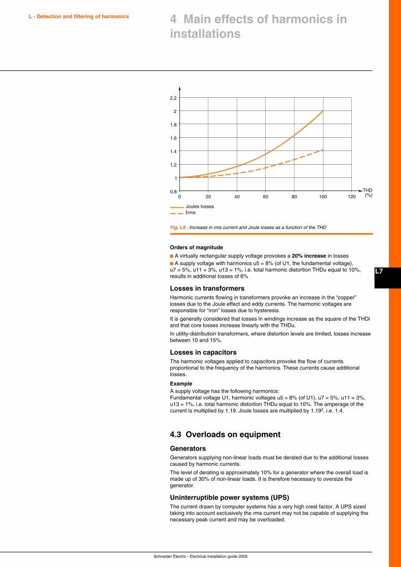
Schneider Electric - Electrical installation guide 2005
L7
L - Detection and filtering of harmonics
Orders of magnitude
c A virtually rectangular supply voltage provokes a 20% increase in lossesc A supply voltage with harmonics u5 = 8% (of U1, the fundamental voltage),u7 = 5%, u11 = 3%, u13 = 1%, i.e. total harmonic distortion THDu equal to 10%,results in additional losses of 6%
Losses in transformersHarmonic currents flowing in transformers provoke an increase in the “copper”losses due to the Joule effect and eddy currents. The harmonic voltages areresponsible for “iron” losses due to hysteresis.
It is generally considered that losses in windings increase as the square of the THDiand that core losses increase linearly with the THDu.
In utility-distribution transformers, where distortion levels are limited, losses increasebetween 10 and 15%.
Losses in capacitorsThe harmonic voltages applied to capacitors provoke the flow of currentsproportional to the frequency of the harmonics. These currents cause additionallosses.
ExampleA supply voltage has the following harmonics:Fundamental voltage U1, harmonic voltages u5 = 8% (of U1), u7 = 5%, u11 = 3%,u13 = 1%, i.e. total harmonic distortion THDu equal to 10%. The amperage of thecurrent is multiplied by 1.19. Joule losses are multiplied by 1.192, i.e. 1.4.
4.3 Overloads on equipment
GeneratorsGenerators supplying non-linear loads must be derated due to the additional lossescaused by harmonic currents.
The level of derating is approximately 10% for a generator where the overall load ismade up of 30% of non-linear loads. It is therefore necessary to oversize thegenerator.
Uninterruptible power systems (UPS)The current drawn by computer systems has a very high crest factor. A UPS sizedtaking into account exclusively the rms current may not be capable of supplying thenecessary peak current and may be overloaded.
0 20 40 60 80 100 120
1
1.2
1.4
1.6
1.8
2
2.2
0.8 THD(%)
Joules lossesIrms
Fig. L8 : Increase in rms current and Joule losses as a function of the THD
4 Main effects of harmonics ininstallations
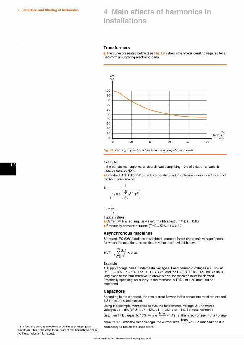
Schneider Electric - Electrical installation guide 2005
L - Detection and filtering of harmonics
L8
Transformersc The curve presented below (see Fig. L9 ) shows the typical derating required for atransformer supplying electronic loads
ExampleIf the transformer supplies an overall load comprising 40% of electronic loads, itmust be derated 40%.c Standard UTE C15-112 provides a derating factor for transformers as a function ofthe harmonic currents.
k1
1 0.1 h 1.6
h 2
40=
+⎛
⎝⎜
⎞
⎠⎟
=∑ Th
2
Th =IIh
1
Typical values:c Current with a rectangular waveform (1/h spectrum (1)): k = 0.86c Frequency-converter current (THD ≈ 50%): k = 0.80
Asynchronous machinesStandard IEC 60892 defines a weighted harmonic factor (Harmonic voltage factor)for which the equation and maximum value are provided below.
HVFU
0.02h
h 2
13=
=∑
∆
h2 i
ExampleA supply voltage has a fundamental voltage U1 and harmonic voltages u3 = 2% ofU1, u5 = 3%, u7 = 1%. The THDu is 3.7% and the HVF is 0.018. The HVF value isvery close to the maximum value above which the machine must be derated.Practically speaking, for supply to the machine, a THDu of 10% must not beexceeded.
CapacitorsAccording to the standard, the rms current flowing in the capacitors must not exceed1.3 times the rated current.
Using the example mentioned above, the fundamental voltage U1, harmonicvoltages u5 = 8% (of U1), u7 = 5%, u11 = 3%, u13 = 1%, i.e. total harmonic
distortion THDu equal to 10%, where II
rms1
= 1 19. , at the rated voltage. For a voltage
equal to 1.1 times the rated voltage, the current limit II
rms1
= 1 3. is reached and it is
necessary to resize the capacitors.(1) In fact, the current waveform is similar to a rectangularwaveform. This is the case for all current rectifiers (three-phaserectifiers, induction furnaces).
%Electronic
load0 20 40 60 80 100
10
20
0
kVA(%)
30
40
50
60
70
80
90
100
Fig. L9 : Derating required for a transformer supplying electronic loads
4 Main effects of harmonics ininstallations
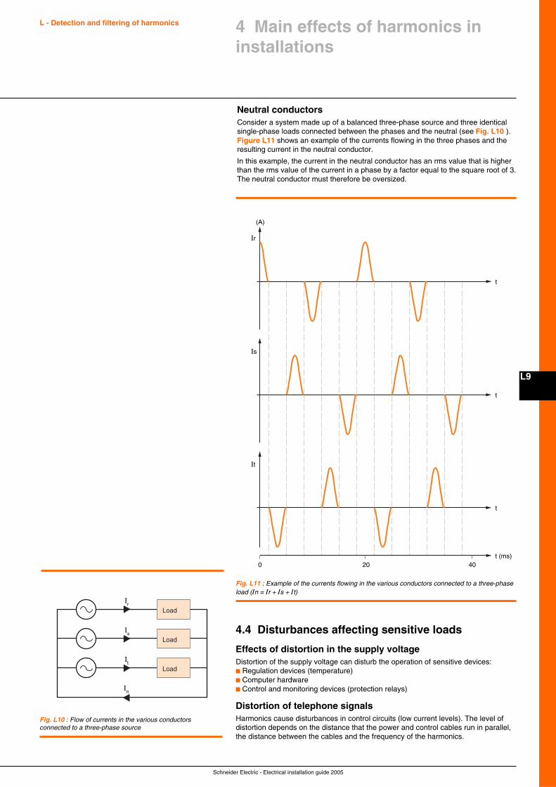
Schneider Electric - Electrical installation guide 2005
L9
L - Detection and filtering of harmonics 4 Main effects of harmonics ininstallations
Is
Ir
It
In
Load
Load
Load
Fig. L10 : Flow of currents in the various conductorsconnected to a three-phase source
Neutral conductorsConsider a system made up of a balanced three-phase source and three identicalsingle-phase loads connected between the phases and the neutral (see Fig. L10 ).Figure L11 shows an example of the currents flowing in the three phases and theresulting current in the neutral conductor.
In this example, the current in the neutral conductor has an rms value that is higherthan the rms value of the current in a phase by a factor equal to the square root of 3.The neutral conductor must therefore be oversized.
Fig. L11 : Example of the currents flowing in the various conductors connected to a three-phaseload (In = Ir + Is + It)
(A)
20 400
It
t (ms)
Is
t
t
Ir
t
4.4 Disturbances affecting sensitive loads
Effects of distortion in the supply voltageDistortion of the supply voltage can disturb the operation of sensitive devices:c Regulation devices (temperature)c Computer hardwarec Control and monitoring devices (protection relays)
Distortion of telephone signalsHarmonics cause disturbances in control circuits (low current levels). The level ofdistortion depends on the distance that the power and control cables run in parallel,the distance between the cables and the frequency of the harmonics.
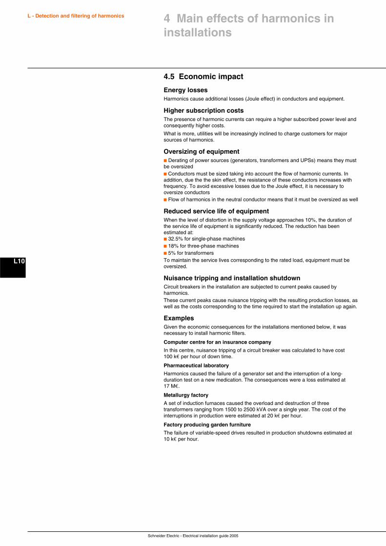
Schneider Electric - Electrical installation guide 2005
L - Detection and filtering of harmonics
L10
4 Main effects of harmonics ininstallations
4.5 Economic impact
Energy lossesHarmonics cause additional losses (Joule effect) in conductors and equipment.
Higher subscription costsThe presence of harmonic currents can require a higher subscribed power level andconsequently higher costs.
What is more, utilities will be increasingly inclined to charge customers for majorsources of harmonics.
Oversizing of equipmentc Derating of power sources (generators, transformers and UPSs) means they mustbe oversizedc Conductors must be sized taking into account the flow of harmonic currents. Inaddition, due the the skin effect, the resistance of these conductors increases withfrequency. To avoid excessive losses due to the Joule effect, it is necessary tooversize conductorsc Flow of harmonics in the neutral conductor means that it must be oversized as well
Reduced service life of equipmentWhen the level of distortion in the supply voltage approaches 10%, the duration ofthe service life of equipment is significantly reduced. The reduction has beenestimated at:c 32.5% for single-phase machinesc 18% for three-phase machinesc 5% for transformersTo maintain the service lives corresponding to the rated load, equipment must beoversized.
Nuisance tripping and installation shutdownCircuit breakers in the installation are subjected to current peaks caused byharmonics.These current peaks cause nuisance tripping with the resulting production losses, aswell as the costs corresponding to the time required to start the installation up again.
ExamplesGiven the economic consequences for the installations mentioned below, it wasnecessary to install harmonic filters.
Computer centre for an insurance company
In this centre, nuisance tripping of a circuit breaker was calculated to have cost100 k€ per hour of down time.
Pharmaceutical laboratory
Harmonics caused the failure of a generator set and the interruption of a long-duration test on a new medication. The consequences were a loss estimated at17 M€.
Metallurgy factory
A set of induction furnaces caused the overload and destruction of threetransformers ranging from 1500 to 2500 kVA over a single year. The cost of theinterruptions in production were estimated at 20 k€ per hour.
Factory producing garden furniture
The failure of variable-speed drives resulted in production shutdowns estimated at10 k€ per hour.
Schneider Electric - Electrical installation guide 2005
L11
A number of indicators are used to quantify and evaluate the harmonic distortionin current and voltage waveforms, namely:c Power factorc Crest factorc Distortion powerc Harmonic spectrumc Harmonic-distortion values
These indicators are indispensable in determining any necessary correctiveaction.
5.1 Power factor
DefinitionThe power factor PF is the ratio between the active power P and the apparentpower S.
PFPS
=
Among electricians, there is often confusion with:
c P1S1
os ϕ =
WhereP1 = active power of the fundamentalS1 = apparent power of the fundamental
The cos ϕ concerns exclusively the fundamental frequency and therefore differsfrom the power factor PF when there are harmonics in the installation.
Interpreting the power factorAn initial indication that there are significant amounts of harmonics is a measuredpower factor PF that is different (lower) than the measured cos ϕ.
5.2 Crest factor
Definition
The crest factor is the ratio between the value of the peak current or voltage (Im orUm) and its rms value.c For a sinusoidal signal, the crest factor is therefore equal to r.c For a non-sinusoidal signal, the crest factor can be either greater than or lessthan r.
In the latter case, the crest factor signals divergent peak values with respect to therms value.
Interpretation of the crest factorThe typical crest factor for the current drawn by non-linear loads is much higherthan r. It is generally between 1.5 and 2 and can even reach 5 in critical cases.A high crest factor signals high transient overcurrents which, when detected byprotection devices, can cause nuisance tripping.
5.3 Power values and harmonics
Active powerThe active power P of a signal comprising harmonics is the sum of the activepowers resulting from the currents and voltages of the same order.
Reactive powerReactive power is defined exclusively in terms of the fundamental, i.e.
Q U1 1 x sin 1= x I ϕ
Distortion powerWhen harmonics are present, the distortion power D is defined asD = (S2 - P2 - Q2)1/2 where S is the apparent power.
5 Essential indicators of harmonicdistortion and measurementprinciples
L - Detection and filtering of harmonics
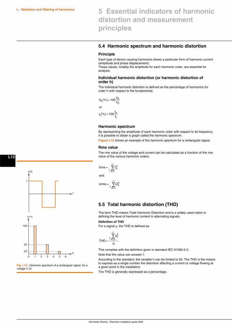
Schneider Electric - Electrical installation guide 2005
L - Detection and filtering of harmonics
L12
5.4 Harmonic spectrum and harmonic distortion
PrincipleEach type of device causing harmonics draws a particular form of harmonic current(amplitude and phase displacement).These values, notably the amplitude for each harmonic order, are essential foranalysis.
Individual harmonic distortion (or harmonic distortion oforder h)The individual harmonic distortion is defined as the percentage of harmonics fororder h with respect to the fundamental.
U % 100UU
or
i % 100
hh
1
hh
1
( ) =
( ) =II
Harmonic spectrumBy representing the amplitude of each harmonic order with respect to its frequency,it is possible to obtain a graph called the harmonic spectrum.
Figure L12 shows an example of the harmonic spectrum for a rectangular signal.
Rms valueThe rms value of the voltage and current can be calculated as a function of the rmsvalue of the various harmonic orders.
I Irms
rms
=
=
=
∞
=
∞
∑
∑
h2
h 1
h2
h 1
and
U U
5.5 Total harmonic distortion (THD)
The term THD means Total Harmonic Distortion and is a widely used notion indefining the level of harmonic content in alternating signals.
Definition of THDFor a signal y, the THD is defined as:
THD h= =
∞
∑y
y
h2
2
1
This complies with the definition given in standard IEC 61000-2-2.
Note that the value can exceed 1.
According to the standard, the variable h can be limited to 50. The THD is the meansto express as a single number the distortion affecting a current or voltage flowing ata given point in the installation.
The THD is generally expressed as a percentage.
U(t)
1
t
2 3 4 5 6
H %
100
33
20
10h
Fig. L12 : Harmonic spectrum of a rectangular signal, for avoltage U (t)
5 Essential indicators of harmonicdistortion and measurementprinciples
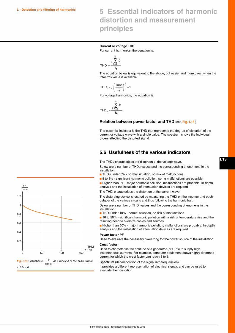
Schneider Electric - Electrical installation guide 2005
L13
L - Detection and filtering of harmonics
Current or voltage THDFor current harmonics, the equation is:
THDih= =
∞
∑ I
I
h2
2
1
The equation below is equivalent to the above, but easier and more direct when thetotal rms value is available:
THDi =⎛
⎝⎜
⎞
⎠⎟ −
IIrms
1
2
1
For voltage harmonics, the equation is:
THD
U
Uuh= =
∞
∑ h2
2
1
Relation between power factor and THD (see Fig. L13 )
The essential indicator is the THD that represents the degree of distortion of thecurrent or voltage wave with a single value. The spectrum shows the individualorders affecting the distorted signal.
5.6 Usefulness of the various indicators
The THDu characterises the distortion of the voltage wave.
Below are a number of THDu values and the corresponding phenomena in theinstallation:c THDu under 5% - normal situation, no risk of malfunctionsc 5 to 8% - significant harmonic pollution, some malfunctions are possiblec Higher than 8% - major harmonic pollution, malfunctions are probable. In-depthanalysis and the installation of attenuation devices are required
The THDi characterises the distortion of the current wave.
The disturbing device is located by measuring the THDi on the incomer and eachoutgoer of the various circuits and thus following the harmonic trail.
Below are a number of THDi values and the corresponding phenomena in theinstallation:c THDi under 10% - normal situation, no risk of malfunctionsc 10 to 50% - significant harmonic pollution with a risk of temperature rise and theresulting need to oversize cables and sourcesc Higher than 50% - major harmonic pollution, malfunctions are probable. In-depthanalysis and the installation of attenuation devices are required
Power factor PFUsed to evaluate the necessary oversizing for the power source of the installation.
Crest factorUsed to characterise the aptitude of a generator (or UPS) to supply highinstantaneous currents. For example, computer equipment draws highly deformedcurrent for which the crest factor can reach 3 to 5.
Spectrum (decomposition of the signal into frequencies)It provides a different representation of electrical signals and can be used toevaluate their distortion.
Fig. L13 : Variation in PFcos ϕ
as a function of the THDi, where
THDu = 0
5 Essential indicators of harmonicdistortion and measurementprinciples
0.6
0.4
0.2
0.8
1
1.2
PFcos ϕ
100500
THDi(%)
150
Schneider Electric - Electrical installation guide 2005
L - Detection and filtering of harmonics
L14
6.1 Devices used to measure the indicators
Device selectionThe traditional observation and measurement methods include:c Observations using an oscilloscopeAn initial indication on the distortion affecting a signal can be obtained by viewing thecurrent or the voltage on an oscilloscope.The waveform, when it diverges from a sinusoidal, clearly indicates the presence ofharmonics. Current and voltage peaks can be viewed.Note, however, that this method does not offer precise quantification of the harmoniccomponentsc Analogue spectral analysersThey are made up of passband filters coupled with an rms voltmeter. They offermediocre performance and do not provide information on phase displacement.Only the recent digital analysers can determine sufficiently precisely the values of allthe mentioned indicators.
Functions of digital analysersThe microprocessors in digital analysers:c Calculate the values of the harmonic indicators (power factor, crest factor,distortion power, THD)c Carry out various complementary functions (corrections, statistical detection,measurement management, display, communication, etc.)c In multi-channel analysers, supply virtually in real time the simultaneous spectraldecomposition of the currents and voltages
Analyser operation and data processingThe analogue signals are converted into a series of numerical values.
Using this data, an algorithm implementing the Fast Fourier Transform (FFT)calculates the amplitudes and the phases of the harmonics over a large number oftime windows.
Most digital analysers measure harmonics up to order 20 or 25 when calculating theTHD.
Processing of the successive values calculated using the FFT (smoothing,classification, statistics) can be carried out by the measurement device or by externalsoftware.
6.2 Procedures for harmonic analysis ofdistribution networks
Measurements are carried out on the industrial or commercial site:c Preventively, to obtain an overall idea on distribution-network status (network map)c In view of corrective action:v To diagnose a disturbance and determine the solutions required to eliminate itv To check the validity of a solution (followed by modifications in the distributionnetwork to check the reduction in harmonics)
Operating modeThe current and voltage are studied:c At the supply sourcec On the busbars of the main distribution switchboard (or on the MV busbars)c On each outgoing circuit in the main distribution switchboard (or on theMV busbars)
For the measurements, it is necessary to know the precise operating conditions ofthe installation and particularly the status of the capacitor banks (operating, notoperating, the number of disconnected steps).
Analysis resultsc Determine any necessary derating of equipment in the installation orc Quantify any necessary harmonic protection and filtering systems to be installed inthe distribution networkc Enable comparison between the measured values and the reference values of theutility (maximum harmonic values, acceptable values, reference values)
6 Measuring the indicators
Schneider Electric - Electrical installation guide 2005
L15
L - Detection and filtering of harmonics
Use of measurement devicesMeasurement devices serve to show both the instantaneous and long-term effects ofharmonics. Analysis requires values spanning durations ranging from a few secondsto several minutes over observation periods of a number of days.
The required values include:c The amplitudes of the harmonic currents and voltagesc The individual harmonic content of each harmonic order of the current and voltagec The THD for the current and voltagec Where applicable, the phase displacement between the harmonic voltage andcurrent of the same harmonic order and the phase of the harmonics with respect to acommon reference (e.g. the fundamental voltage)
6.3 Keeping a close eye on harmonics
The harmonic indicators can be measured:c Either by devices permanently installed in the distribution networkc Or by an expert present at least a half day on the site (limited perception)
Permanent devices are preferableFor a number of reasons, the installation of permanent measurement devices in thedistribution network is preferable.c The presence of an expert is limited in time. Only a number of measurements atdifferent points in the installation and over a sufficiently long period (one week to amonth) provide an overall view of operation and take into account all the situationsthat can occur following:v Fluctuations in the supply sourcev Variations in the operation of the installationv The addition of new equipment in the installationc Measurement devices installed in the distribution network prepare and facilitate thediagnosis of the experts, thus reducing the number and duration of their visitsc Permanent measurement devices detect any new disturbances arising followingthe installation of new equipment, the implementation of new operating modes orfluctuations in the supply network
Take advantage of built-in measurement and detection devicesMeasurement and detection devices built into the electrical distribution equipment:c For an overall evaluation of network status (preventive analysis), avoid:v Renting measurement equipmentv Calling in expertsv Having to connect and disconnect the measurement equipment.
For the overall evaluation of network status, the analysis on the main low-voltagedistribution switchboards (MLVS) can often be carried out by the incoming deviceand/or the measurement devices equipping each outgoing circuitc For corrective action, are the means to:v Determine the operating conditions at the time of the incidentv Draw up a map of the distribution network and evaluate the implemented solution
The diagnosis is improved by the use of equipment intended for the studied problem.
6 Measuring the indicators
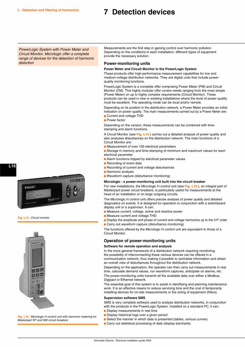
Schneider Electric - Electrical installation guide 2005
L - Detection and filtering of harmonics
L16
7 Detection devices
PowerLogic System with Power Meter andCircuit Monitor, Micrologic offer a completerange of devices for the detection of harmonicdistortion
Measurements are the first step in gaining control over harmonic pollution.Depending on the conditions in each installation, different types of equipmentprovide the necessary solution.
Power-monitoring unitsPower Meter and Circuit Monitor in the PowerLogic SystemThese products offer high-performance measurement capabilities for low andmedium-voltage distribution networks. They are digital units that include power-quality monitoring functions.
PowerLogic System is a complete offer comprising Power Meter (PM) and CircuitMonitor (CM). This highly modular offer covers needs ranging from the most simple(Power Meter) on up to highly complex requirements (Circuit Monitor). Theseproducts can be used in new or existing installations where the level of power qualitymust be excellent. The operating mode can be local and/or remote.
Depending on its position in the distribution network, a Power Meter provides an initialindication on power quality. The main measurements carried out by a Power Meter are:c Current and voltage THDc Power factor
Depending on the version, these measurements can be combined with time-stamping and alarm functions.
A Circuit Monitor (see Fig. L14 ) carries out a detailed analysis of power quality andalso analyses disturbances on the distribution network. The main functions of aCircuit Monitor are:c Measurement of over 100 electrical parametersc Storage in memory and time-stamping of minimum and maximum values for eachelectrical parameterc Alarm functions tripped by electrical parameter valuesc Recording of event datac Recording of current and voltage disturbancesc Harmonic analysisc Waveform capture (disturbance monitoring)
Micrologic - a power-monitoring unit built into the circuit breakerFor new installations, the Micrologic H control unit (see Fig. L15 ), an integral part ofMasterpact power circuit breakers, is particularly useful for measurements at thehead of an installation or on large outgoing circuits.
The Micrologic H control unit offers precise analysis of power quality and detaileddiagnostics on events. It is designed for operation in conjunction with a switchboarddisplay unit or a supervisor. It can:c Measure current, voltage, active and reactive powerc Measure current and voltage THDc Display the amplitude and phase of current and voltage harmonics up to the 51st orderc Carry out waveform capture (disturbance monitoring)
The functions offered by the Micrologic H control unit are equivalent to those of aCircuit Monitor.
Operation of power-monitoring unitsSoftware for remote operation and analysisIn the more general framework of a distribution network requiring monitoring,the possibility of interconnecting these various devices can be offered in acommunication network, thus making it possible to centralise information and obtainan overall view of disturbances throughout the distribution network.Depending on the application, the operator can then carry out measurements in realtime, calculate demand values, run waveform captures, anticipate on alarms, etc.The power-monitoring units transmit all the available data over either a Modbus,Digipact or Ethernet network.The essential goal of this system is to assist in identifying and planning maintenancework. It is an effective means to reduce servicing time and the cost of temporarilyinstalling devices for on-site measurements or the sizing of equipment (filters).
Supervision software SMSSMS is very complete software used to analyse distribution networks, in conjunctionwith the products in the PowerLogic System. Installed on a standard PC, it can:c Display measurements in real timec Display historical logs over a given periodc Select the manner in which data is presented (tables, various curves)c Carry out statistical processing of data (display barcharts)
Fig. L14 : Circuit monitor
Fig. L15 : Micrologic H control unit with harmonic metering forMasterpact NT and NW circuit breakers
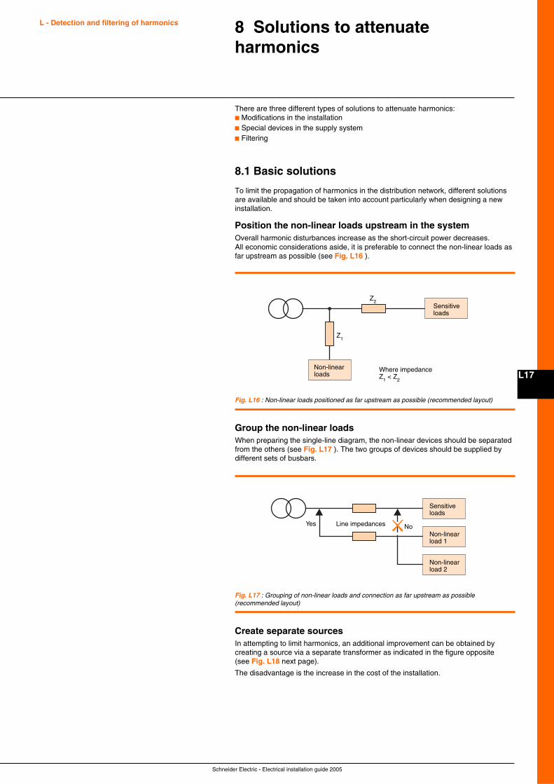
Schneider Electric - Electrical installation guide 2005
L17
8 Solutions to attenuateharmonics
There are three different types of solutions to attenuate harmonics:c Modifications in the installationc Special devices in the supply systemc Filtering
8.1 Basic solutions
To limit the propagation of harmonics in the distribution network, different solutionsare available and should be taken into account particularly when designing a newinstallation.
Position the non-linear loads upstream in the systemOverall harmonic disturbances increase as the short-circuit power decreases.All economic considerations aside, it is preferable to connect the non-linear loads asfar upstream as possible (see Fig. L16 ).
Fig. L16 : Non-linear loads positioned as far upstream as possible (recommended layout)
Sensitive loads
Z2
Z1
Non-linear loads
Where impedanceZ1 < Z2
Group the non-linear loadsWhen preparing the single-line diagram, the non-linear devices should be separatedfrom the others (see Fig. L17 ). The two groups of devices should be supplied bydifferent sets of busbars.
Sensitive loads
Line impedances
Non-linear load 1
Non-linear load 2
Yes No
Fig. L17 : Grouping of non-linear loads and connection as far upstream as possible(recommended layout)
Create separate sourcesIn attempting to limit harmonics, an additional improvement can be obtained bycreating a source via a separate transformer as indicated in the figure opposite(see Fig. L18 next page).
The disadvantage is the increase in the cost of the installation.
L - Detection and filtering of harmonics
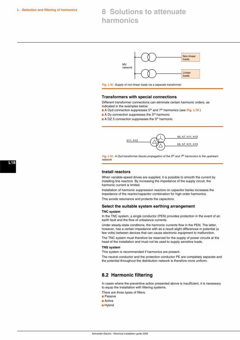
Schneider Electric - Electrical installation guide 2005
L - Detection and filtering of harmonics
L18
Non-linear loads
Linear loads
MV network
Fig. L18 : Supply of non-linear loads via a separate transformer
Transformers with special connectionsDifferent transformer connections can eliminate certain harmonic orders, asindicated in the examples below:c A Dyd connection suppresses 5th and 7th harmonics (see Fig. L19 )c A Dy connection suppresses the 3rd harmonicc A DZ 5 connection suppresses the 5th harmonic
h11, h13h5, h7, h11, h13
h5, h7, h11, h13
Fig. L19 : A Dyd transformer blocks propagation of the 5th and 7th harmonics to the upstreamnetwork
Install reactorsWhen variable-speed drives are supplied, it is possible to smooth the current byinstalling line reactors. By increasing the impedance of the supply circuit, theharmonic current is limited.
Installation of harmonic suppression reactors on capacitor banks increases theimpedance of the reactor/capacitor combination for high-order harmonics.
This avoids resonance and protects the capacitors.
Select the suitable system earthing arrangementTNC systemIn the TNC system, a single conductor (PEN) provides protection in the event of anearth fault and the flow of unbalance currents.
Under steady-state conditions, the harmonic currents flow in the PEN. The latter,however, has a certain impedance with as a result slight differences in potential (afew volts) between devices that can cause electronic equipment to malfunction.
The TNC system must therefore be reserved for the supply of power circuits at thehead of the installation and must not be used to supply sensitive loads.
TNS systemThis system is recommended if harmonics are present.
The neutral conductor and the protection conductor PE are completely separate andthe potential throughout the distribution network is therefore more uniform.
8.2 Harmonic filtering
In cases where the preventive action presented above is insufficient, it is necessaryto equip the installation with filtering systems.
There are three types of filters:c Passivec Activec Hybrid
8 Solutions to attenuateharmonics
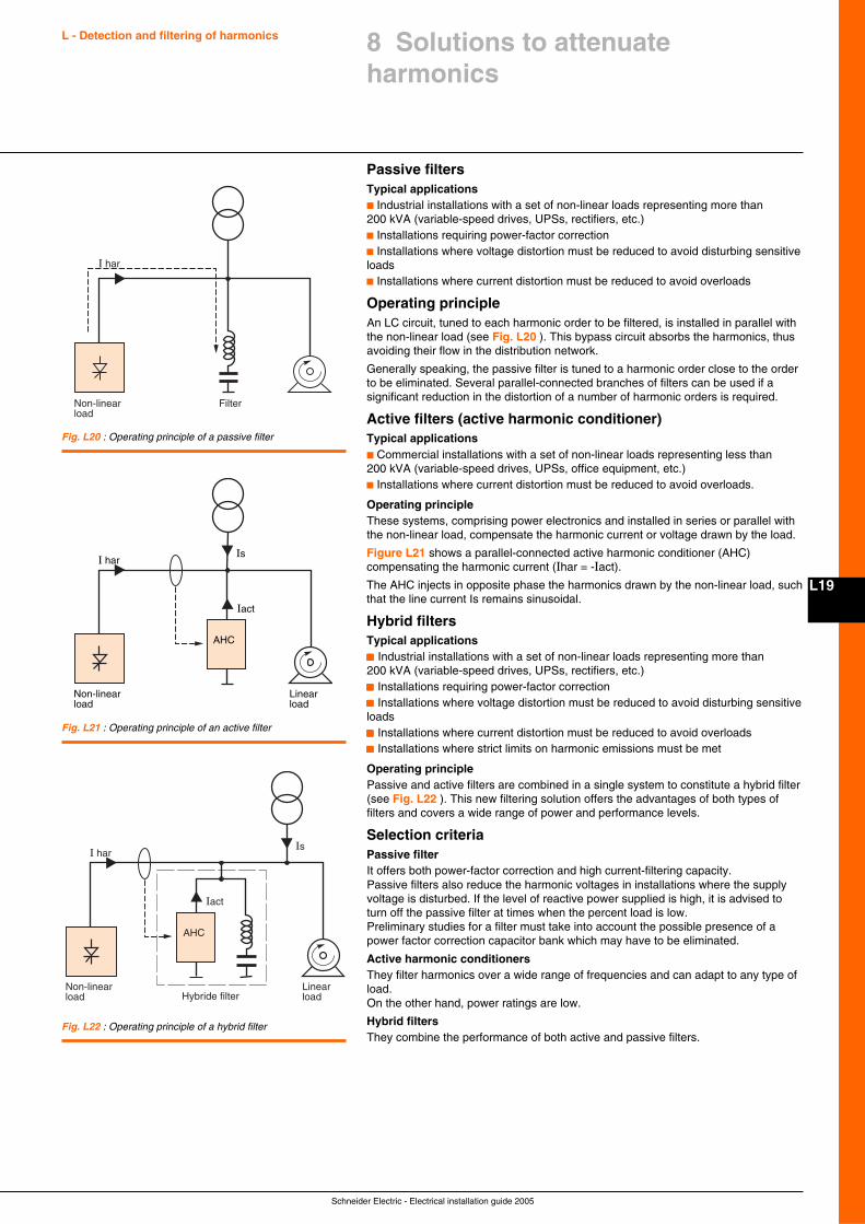
Schneider Electric - Electrical installation guide 2005
L19
L - Detection and filtering of harmonics
Passive filtersTypical applicationsc Industrial installations with a set of non-linear loads representing more than200 kVA (variable-speed drives, UPSs, rectifiers, etc.)c Installations requiring power-factor correctionc Installations where voltage distortion must be reduced to avoid disturbing sensitiveloadsc Installations where current distortion must be reduced to avoid overloads
Operating principleAn LC circuit, tuned to each harmonic order to be filtered, is installed in parallel withthe non-linear load (see Fig. L20 ). This bypass circuit absorbs the harmonics, thusavoiding their flow in the distribution network.
Generally speaking, the passive filter is tuned to a harmonic order close to the orderto be eliminated. Several parallel-connected branches of filters can be used if asignificant reduction in the distortion of a number of harmonic orders is required.
Active filters (active harmonic conditioner)Typical applicationsc Commercial installations with a set of non-linear loads representing less than200 kVA (variable-speed drives, UPSs, office equipment, etc.)c Installations where current distortion must be reduced to avoid overloads.
Operating principleThese systems, comprising power electronics and installed in series or parallel withthe non-linear load, compensate the harmonic current or voltage drawn by the load.
Figure L21 shows a parallel-connected active harmonic conditioner (AHC)compensating the harmonic current (Ihar = -Iact).
The AHC injects in opposite phase the harmonics drawn by the non-linear load, suchthat the line current Is remains sinusoidal.
Hybrid filtersTypical applicationsccccc Industrial installations with a set of non-linear loads representing more than200 kVA (variable-speed drives, UPSs, rectifiers, etc.)ccccc Installations requiring power-factor correctionccccc Installations where voltage distortion must be reduced to avoid disturbing sensitiveloadsccccc Installations where current distortion must be reduced to avoid overloadsccccc Installations where strict limits on harmonic emissions must be met
Operating principlePassive and active filters are combined in a single system to constitute a hybrid filter(see Fig. L22 ). This new filtering solution offers the advantages of both types offilters and covers a wide range of power and performance levels.
Selection criteriaPassive filterIt offers both power-factor correction and high current-filtering capacity.Passive filters also reduce the harmonic voltages in installations where the supplyvoltage is disturbed. If the level of reactive power supplied is high, it is advised toturn off the passive filter at times when the percent load is low.Preliminary studies for a filter must take into account the possible presence of apower factor correction capacitor bank which may have to be eliminated.
Active harmonic conditionersThey filter harmonics over a wide range of frequencies and can adapt to any type ofload.On the other hand, power ratings are low.
Hybrid filtersThey combine the performance of both active and passive filters.
Fig. L22 : Operating principle of a hybrid filter
Fig. L20 : Operating principle of a passive filter
Non-linear load
I har
Filter
Non-linear load
Linear load
AHC
IsI har
Iact
Fig. L21 : Operating principle of an active filter
Non-linear load
Linear load
AHC
IsI har
Iact
Hybride filter
8 Solutions to attenuateharmonics
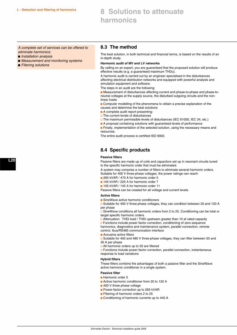
Schneider Electric - Electrical installation guide 2005
L - Detection and filtering of harmonics
L20
A complete set of services can be offered toeliminate harmonics:c Installation analysisc Measurement and monitoring systemsc Filtering solutions
8.3 The methodThe best solution, in both technical and financial terms, is based on the results of anin-depth study.
Harmonic audit of MV and LV networksBy calling on an expert, you are guaranteed that the proposed solution will produceeffective results (e.g. a guaranteed maximum THDu).A harmonic audit is carried out by an engineer specialised in the disturbancesaffecting electrical distribution networks and equipped with powerful analysis andsimulation equipment and software.The steps in an audit are the following:c Measurement of disturbances affecting current and phase-to-phase and phase-to-neutral voltages at the supply source, the disturbed outgoing circuits and the non-linear loadsc Computer modelling of the phenomena to obtain a precise explanation of thecauses and determine the best solutionsc A complete audit report presenting:v The current levels of disturbancesv The maximum permissible levels of disturbances (IEC 61000, IEC 34, etc.)c A proposal containing solutions with guaranteed levels of performancec Finally, implementation of the selected solution, using the necessary means andresources.The entire audit process is certified ISO 9002.
8.4 Specific productsPassive filtersPassive filters are made up of coils and capacitors set up in resonant circuits tunedto the specific harmonic order that must be eliminated.A system may comprise a number of filters to eliminate several harmonic orders.Suitable for 400 V three-phase voltages, the power ratings can reach:c 265 kVAR / 470 A for harmonic order 5c 145 kVAR / 225 A for harmonic order 7c 105 kVAR / 145 A for harmonic order 11Passive filters can be created for all voltage and current levels.
Active filtersc SineWave active harmonic conditionersv Suitable for 400 V three-phase voltages, they can condition between 20 and 120 Aper phasev SineWave conditions all harmonic orders from 2 to 25. Conditioning can be total ortarget specific harmonic ordersv Attenuation: THDi load / THDi upstream greater than 10 at rated capacityv Functions include power factor correction, conditioning of zero-sequenceharmonics, diagnostics and maintenance system, parallel connection, remotecontrol, Ibus/RS485 communication interfacec Accusine active filtersv Suitable for 400 and 480 V three-phase voltages, they can filter between 50 and30 A per phasev All harmonic orders up to 50 are filteredv Functions include power factor correction, parallel connection, instantaneousresponse to load variations
Hybrid filtersThese filters combine the advantages of both a passive filter and the SineWaveactive harmonic conditioner in a single system.
Passive filterc Harmonic order 5c Active harmonic conditioner from 20 to 120 Ac 400 V three-phase voltagec Power-factor correction up to 265 kVARc Filtering of harmonic orders 2 to 25c Conditioning of harmonic currents up to 440 A
8 Solutions to attenuateharmonics
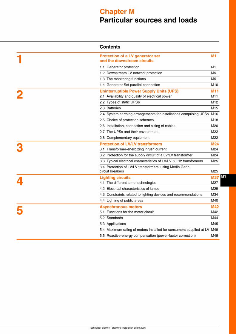
Schneider Electric - Electrical installation guide 2005
M1
Chapter MParticular sources and loads
Contents
Protection of a LV generator set M1and the downstream circuits
1.1 Generator protection M1
1.2 Downstream LV network protection M5
1.3 The monitoring functions M5
1.4 Generator Set parallel-connection M10
Uninterruptible Power Supply Units (UPS) M112.1 Availability and quality of electrical power M11
2.2 Types of static UPSs M12
2.3 Batteries M15
2.4 System earthing arrangements for installations comprising UPSs M16
2.5 Choice of protection schemes M18
2.6 Installation, connection and sizing of cables M20
2.7 The UPSs and their environment M22
2.8 Complementary equipment M22
Protection of LV/LV transformers M243.1 Transformer-energizing inrush current M24
3.2 Protection for the supply circuit of a LV/LV transformer M24
3.3 Typical electrical characteristics of LV/LV 50 Hz transformers M25
3.4 Protection of LV/LV transformers, using Merlin Gerincircuit breakers M25
Lighting circuits M274.1 The different lamp technologies M27
4.2 Electrical characteristics of lamps M29
4.3 Constraints related to lighting devices and recommendations M34
4.4 Lighting of public areas M40
Asynchronous motors M425.1 Functions for the motor circuit M42
5.2 Standards M44
5.3 Applications M45
5.4 Maximum rating of motors installed for consumers supplied at LV M49
5.5 Reactive-energy compensation (power-factor correction) M49
5
4
3
2
1
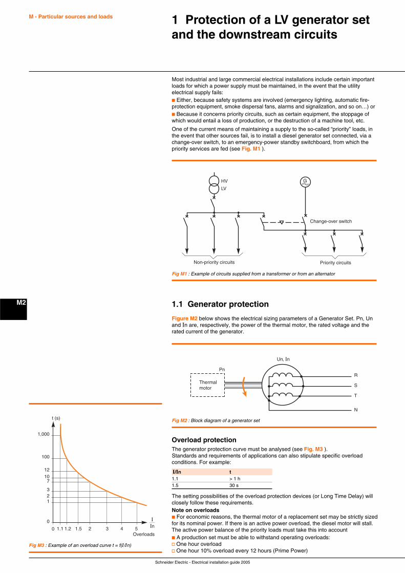
Schneider Electric - Electrical installation guide 2005
M - Particular sources and loads
M2
1 Protection of a LV generator setand the downstream circuits
Most industrial and large commercial electrical installations include certain importantloads for which a power supply must be maintained, in the event that the utilityelectrical supply fails:c Either, because safety systems are involved (emergency lighting, automatic fire-protection equipment, smoke dispersal fans, alarms and signalization, and so on…) orc Because it concerns priority circuits, such as certain equipment, the stoppage ofwhich would entail a loss of production, or the destruction of a machine tool, etc.
One of the current means of maintaining a supply to the so-called “priority” loads, inthe event that other sources fail, is to install a diesel generator set connected, via achange-over switch, to an emergency-power standby switchboard, from which thepriority services are fed (see Fig. M1 ).
G
Change-over switch
Priority circuitsNon-priority circuits
HV
LV
Fig M1 : Example of circuits supplied from a transformer or from an alternator
1.1 Generator protection
Figure M2 below shows the electrical sizing parameters of a Generator Set. Pn, Unand In are, respectively, the power of the thermal motor, the rated voltage and therated current of the generator.
Fig M2 : Block diagram of a generator set
Thermalmotor
R
Un, In
Pn
S
T
N
Overload protectionThe generator protection curve must be analysed (see Fig. M3 ).Standards and requirements of applications can also stipulate specific overloadconditions. For example:
t (s)
1
0
0
32
1.1
71012
100
1,000
Overloads1.2 1.5 2 3 4 5
IIn
Fig M3 : Example of an overload curve t = f(I/In)
I/In t1.1 > 1 h1.5 30 s
The setting possibilities of the overload protection devices (or Long Time Delay) willclosely follow these requirements.Note on overloadsc For economic reasons, the thermal motor of a replacement set may be strictly sizedfor its nominal power. If there is an active power overload, the diesel motor will stall.The active power balance of the priority loads must take this into accountc A production set must be able to withstand operating overloads:v One hour overloadv One hour 10% overload every 12 hours (Prime Power)
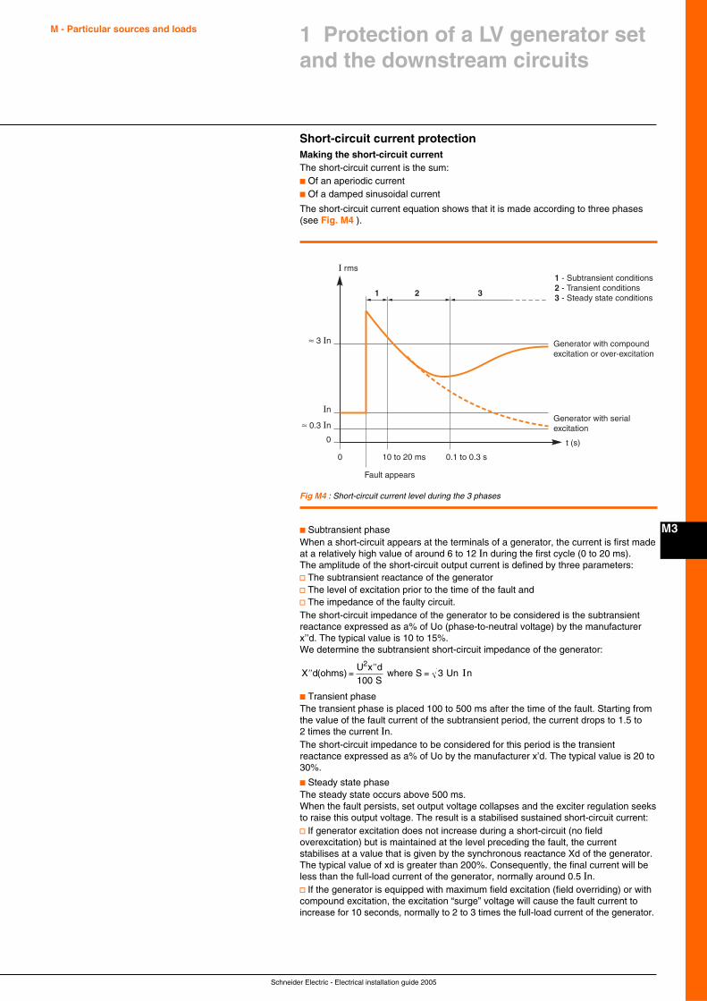
Schneider Electric - Electrical installation guide 2005
M - Particular sources and loads
M3
1 Protection of a LV generator setand the downstream circuits
Short-circuit current protectionMaking the short-circuit currentThe short-circuit current is the sum:c Of an aperiodic currentc Of a damped sinusoidal current
The short-circuit current equation shows that it is made according to three phases(see Fig. M4 ).
Fig M4 : Short-circuit current level during the 3 phases
I rms
≈ 0.3 In
≈ 3 In
In
Generator with compound excitation or over-excitation
Generator with serial excitation
t (s)
Fault appears
10 to 20 ms0
0
0.1 to 0.3 s
1 - Subtransient conditions2 - Transient conditions3 - Steady state conditions1 2 3
c Subtransient phaseWhen a short-circuit appears at the terminals of a generator, the current is first madeat a relatively high value of around 6 to 12 In during the first cycle (0 to 20 ms).The amplitude of the short-circuit output current is defined by three parameters:v The subtransient reactance of the generatorv The level of excitation prior to the time of the fault andv The impedance of the faulty circuit.The short-circuit impedance of the generator to be considered is the subtransientreactance expressed as a% of Uo (phase-to-neutral voltage) by the manufacturerx’’d. The typical value is 10 to 15%.We determine the subtransient short-circuit impedance of the generator:
′′ =′′
=X dU x d
S(ohms)
where S Un n
2
1003 I
c Transient phaseThe transient phase is placed 100 to 500 ms after the time of the fault. Starting fromthe value of the fault current of the subtransient period, the current drops to 1.5 to2 times the current In.The short-circuit impedance to be considered for this period is the transientreactance expressed as a% of Uo by the manufacturer x’d. The typical value is 20 to30%.
c Steady state phaseThe steady state occurs above 500 ms.When the fault persists, set output voltage collapses and the exciter regulation seeksto raise this output voltage. The result is a stabilised sustained short-circuit current:v If generator excitation does not increase during a short-circuit (no fieldoverexcitation) but is maintained at the level preceding the fault, the currentstabilises at a value that is given by the synchronous reactance Xd of the generator.The typical value of xd is greater than 200%. Consequently, the final current will beless than the full-load current of the generator, normally around 0.5 In.v If the generator is equipped with maximum field excitation (field overriding) or withcompound excitation, the excitation “surge” voltage will cause the fault current toincrease for 10 seconds, normally to 2 to 3 times the full-load current of the generator.
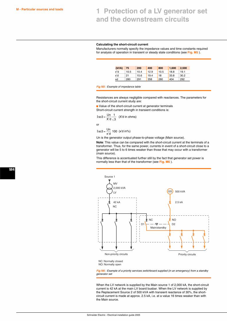
Schneider Electric - Electrical installation guide 2005
M - Particular sources and loads
M4
Calculating the short-circuit currentManufacturers normally specify the impedance values and time constants requiredfor analysis of operation in transient or steady state conditions (see Fig. M5 ).
Fig M5 : Example of impedance table
(kVA) 75 200 400 800 1,600 2,500x”d 10.5 10.4 12.9 10.5 18.8 19.1x’d 21 15.6 19.4 18 33.8 30.2xd 280 291 358 280 404 292
Resistances are always negligible compared with reactances. The parameters forthe short-circuit current study are:
c Value of the short-circuit current at generator terminalsShort-circuit current strength in transient conditions is:
Isc3 =′
UnX d
1
3 (X’d in ohms)
or
Isc3 =′
Unx d
100 (x’d in%)
Un is the generator output phase-to-phase voltage (Main source).
Note: This value can be compared with the short-circuit current at the terminals of atransformer. Thus, for the same power, currents in event of a short-circuit close to agenerator will be 5 to 6 times weaker than those that may occur with a transformer(main source).
This difference is accentuated further still by the fact that generator set power isnormally less than that of the transformer (see Fig. M6 ).
Fig M6 : Example of a priority services switchboard supplied (in an emergency) from a standbygenerator set
GS
Priority circuitsNon-priority circuits
MV
Source 1
Main/standby
NC NO
NC: Normally closedNO: Normally open
NC
D1 D2
2,000 kVA
42 kA
500 kVA
2.5 kA
LV
When the LV network is supplied by the Main source 1 of 2,000 kA, the short-circuitcurrent is 42 kA at the main LV board busbar. When the LV network is supplied bythe Replacement Source 2 of 500 kVA with transient reactance of 30%, the short-circuit current is made at approx. 2.5 kA, i.e. at a value 16 times weaker than withthe Main source.
1 Protection of a LV generator setand the downstream circuits
Schneider Electric - Electrical installation guide 2005
M - Particular sources and loads
M5
1 Protection of a LV generator setand the downstream circuits
1.2 Downstream LV network protection
Priority circuit protectionChoice of breaking capacityThis must be systematically checked with the characteristics of the main source(HV/LV transformer).
Choice and setting of the Short Time Delay releasesc Subdistribution boardsThe ratings of the protection devices for the subdistribution and final distributioncircuits are always lower than generator set rated current. Consequently, except inspecial cases, conditions are similar to supply by the transformer.
c Main LV switchboardv The sizing of the main feeder protection devices is normally similar to that of thegenerator set. Setting of the STD must allow for the short-circuit characteristic of thegenerator set (see “Short-circuit current protection” before)v Discrimination of protection devices on the priority feeders must be provided ingenerator set operation (it can even be compulsory for safety feeders). It isnecessary to check proper staggering of STD setting of the protection devices of themain feeders with that of the subdistribution protection devices downstream(normally set for distribution circuits at 10 In).
Note: When operating on the generator set, use of a low sensitivity Residual CurrentDevice enables management of the insulation fault and ensures very simplediscrimination.
Safety of peopleIn the IT (2nd fault) and TN grounding systems, protection of people against indirectcontacts is provided by the STD protection of circuit-breakers. Their operation on afault must be ensured, whether the installation is supplied by the main source(Transformer) or by the replacement source (generator set).
Calculating the insulation fault currentZero-sequence reactance formulated as a% of Uo by the manufacturer x’o.The typical value is 8%.The phase-to-neutral single-phase short-circuit current is given by:
I f X o
=′ + ′
UnX d
32
The insulation fault current in the TN system is slightly greater than the threephasefault current. For example, in event of an insulation fault on the system in theprevious example, the insulation fault current is equal to 3 kA.
1.3 The monitoring functions
Due to the specific characteristics of the generator and its regulation, the properoperating parameters of the generator set must be monitored when special loads areimplemented.
The behaviour of the generator is different from that of the transformer:c The active power it supplies is optimised for a power factor = 0.8c At less than power factor 0.8, the generator may, by increased excitation, supplypart of the reactive power
Capacitor bankAn off-load generator connected to a capacitor bank may self-arc, consequentlyincreasing its overvoltage.The capacitor banks used for power factor regulation must therefore be disconnected.This operation can be performed by sending the stopping setpoint to the regulator(if it is connected to the system managing the source switchings) or by opening thecircuit-breaker supplying the capacitors.If capacitors continue to be necessary, do not use regulation of the power factorrelay in this case (incorrect and over-slow setting).
Motor restart and re-accelerationA generator can supply at most in transient period a current of between 3 and 5 timesits nominal current.A motor absorbs roughly 6 In for 2 to 20 s during start-up.
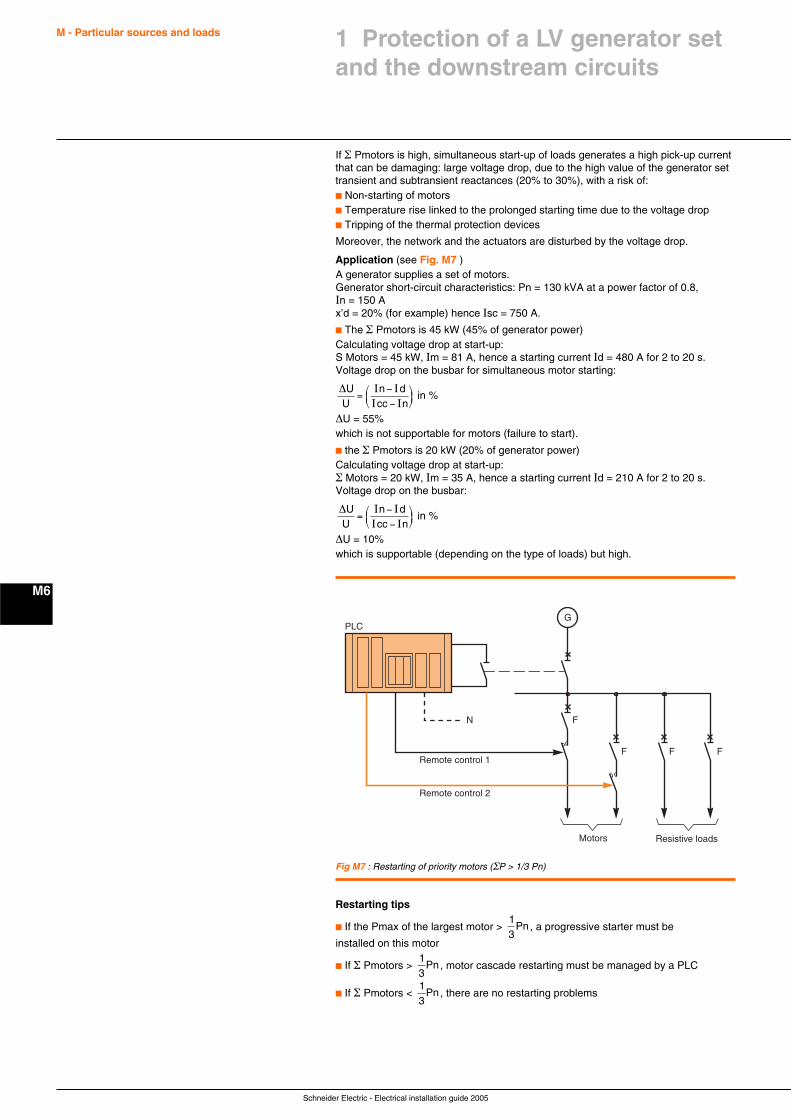
Schneider Electric - Electrical installation guide 2005
M - Particular sources and loads
M6
If Σ Pmotors is high, simultaneous start-up of loads generates a high pick-up currentthat can be damaging: large voltage drop, due to the high value of the generator settransient and subtransient reactances (20% to 30%), with a risk of:c Non-starting of motorsc Temperature rise linked to the prolonged starting time due to the voltage dropc Tripping of the thermal protection devices
Moreover, the network and the actuators are disturbed by the voltage drop.
Application (see Fig. M7 )A generator supplies a set of motors.Generator short-circuit characteristics: Pn = 130 kVA at a power factor of 0.8,In = 150 Ax’d = 20% (for example) hence Isc = 750 A.
c The Σ Pmotors is 45 kW (45% of generator power)Calculating voltage drop at start-up:S Motors = 45 kW, Im = 81 A, hence a starting current Id = 480 A for 2 to 20 s.Voltage drop on the busbar for simultaneous motor starting:
∆UU
n dcc n
=−−
⎛⎝⎜
⎞⎠⎟
I II I
in %
∆U = 55%which is not supportable for motors (failure to start).
c the Σ Pmotors is 20 kW (20% of generator power)Calculating voltage drop at start-up:Σ Motors = 20 kW, Im = 35 A, hence a starting current Id = 210 A for 2 to 20 s.Voltage drop on the busbar:
∆UU
n dcc n
=−−
⎛⎝⎜
⎞⎠⎟
I II I
in %
∆U = 10%which is supportable (depending on the type of loads) but high.
Fig M7 : Restarting of priority motors (ΣP > 1/3 Pn)
G
Resistive loadsMotors
PLC
FN
Remote control 1
Remote control 2
F F F
Restarting tips
c If the Pmax of the largest motor > 13
Pn, a progressive starter must be
installed on this motor
c If Σ Pmotors > 13
Pn, motor cascade restarting must be managed by a PLC
c If Σ Pmotors < 13
Pn, there are no restarting problems
1 Protection of a LV generator setand the downstream circuits
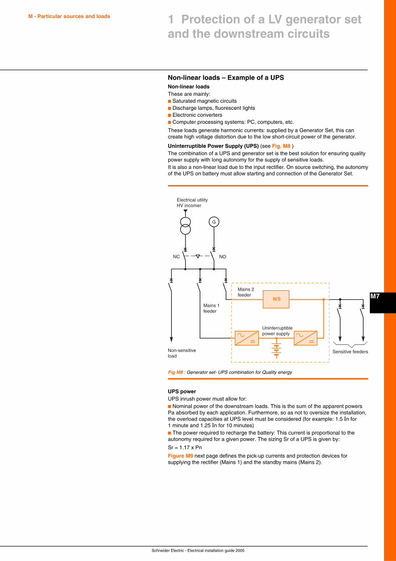
Schneider Electric - Electrical installation guide 2005
M - Particular sources and loads
M7
1 Protection of a LV generator setand the downstream circuits
Non-linear loads – Example of a UPSNon-linear loadsThese are mainly:c Saturated magnetic circuitsc Discharge lamps, fluorescent lightsc Electronic convertersc Computer processing systems: PC, computers, etc.
These loads generate harmonic currents: supplied by a Generator Set, this cancreate high voltage distortion due to the low short-circuit power of the generator.
Uninterruptible Power Supply (UPS) (see Fig. M8 )The combination of a UPS and generator set is the best solution for ensuring qualitypower supply with long autonomy for the supply of sensitive loads.It is also a non-linear load due to the input rectifier. On source switching, the autonomyof the UPS on battery must allow starting and connection of the Generator Set.
Fig M8 : Generator set- UPS combination for Quality energy
G
Sensitive feeders
Mains 2feeder
Mains 1feeder
Uninterruptiblepower supply
Non-sensitiveload
Electrical utilityHV incomer
NC NO
N/S
UPS powerUPS inrush power must allow for:c Nominal power of the downstream loads. This is the sum of the apparent powersPa absorbed by each application. Furthermore, so as not to oversize the installation,the overload capacities at UPS level must be considered (for example: 1.5 In for1 minute and 1.25 In for 10 minutes)c The power required to recharge the battery: This current is proportional to theautonomy required for a given power. The sizing Sr of a UPS is given by:
Sr = 1.17 x Pn
Figure M9 next page defines the pick-up currents and protection devices forsupplying the rectifier (Mains 1) and the standby mains (Mains 2).
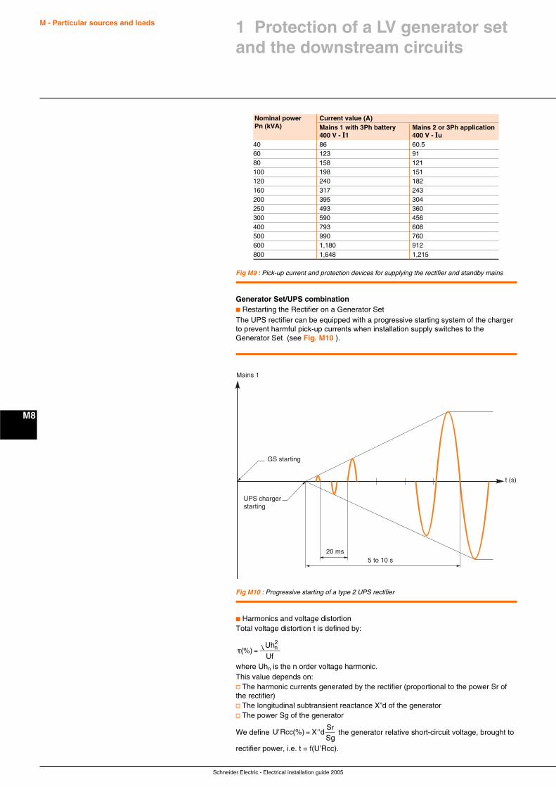
Schneider Electric - Electrical installation guide 2005
M - Particular sources and loads
M8
Generator Set/UPS combinationc Restarting the Rectifier on a Generator SetThe UPS rectifier can be equipped with a progressive starting system of the chargerto prevent harmful pick-up currents when installation supply switches to theGenerator Set (see Fig. M10 ).
Fig M9 : Pick-up current and protection devices for supplying the rectifier and standby mains
Nominal power Current value (A)Pn (kVA) Mains 1 with 3Ph battery Mains 2 or 3Ph application
400 V - I1 400 V - Iu40 86 60.560 123 9180 158 121100 198 151120 240 182160 317 243200 395 304250 493 360300 590 456400 793 608500 990 760600 1,180 912800 1,648 1,215
Fig M10 : Progressive starting of a type 2 UPS rectifier
20 ms5 to 10 s
t (s)
Mains 1
GS starting
UPS chargerstarting
c Harmonics and voltage distortionTotal voltage distortion t is defined by:
τ(%) =Uh
Ufn2
where Uhn is the n order voltage harmonic.This value depends on:v The harmonic currents generated by the rectifier (proportional to the power Sr ofthe rectifier)v The longitudinal subtransient reactance X”d of the generatorv The power Sg of the generator
We define ′ = ′′U Rcc X dSrSg
(%) the generator relative short-circuit voltage, brought to
rectifier power, i.e. t = f(U’Rcc).
1 Protection of a LV generator setand the downstream circuits
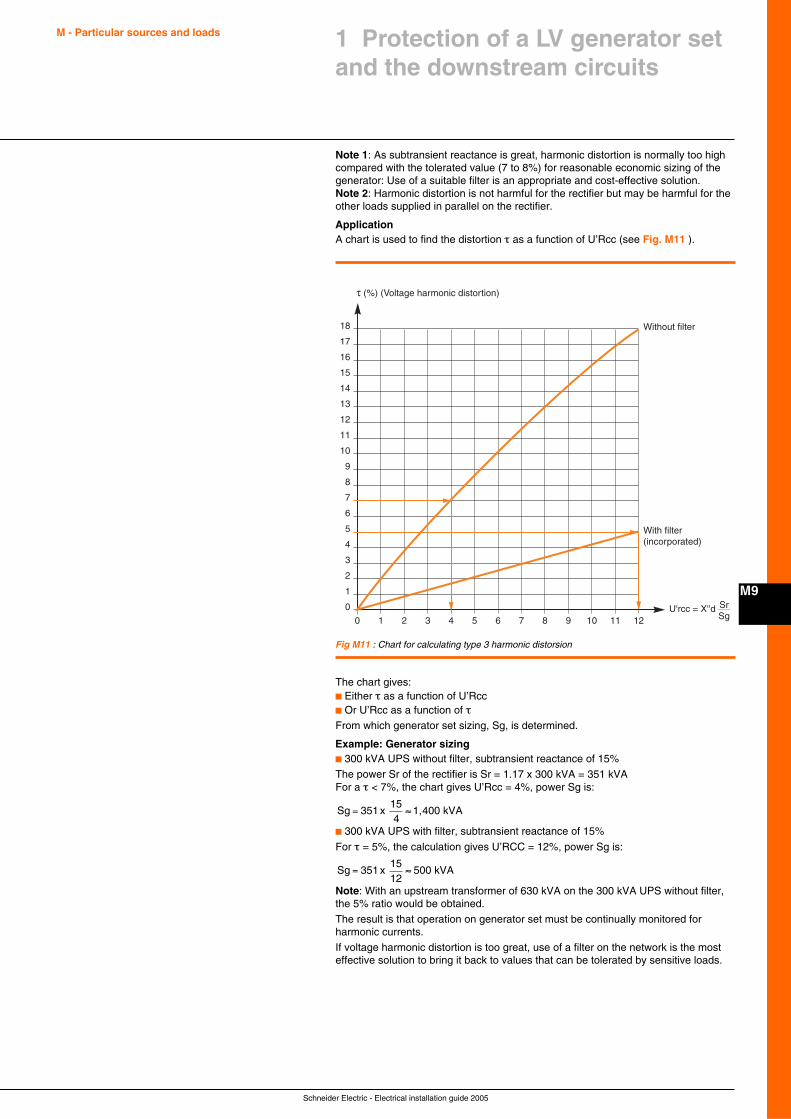
Schneider Electric - Electrical installation guide 2005
M - Particular sources and loads
M9
1 Protection of a LV generator setand the downstream circuits
Note 1: As subtransient reactance is great, harmonic distortion is normally too highcompared with the tolerated value (7 to 8%) for reasonable economic sizing of thegenerator: Use of a suitable filter is an appropriate and cost-effective solution.Note 2: Harmonic distortion is not harmful for the rectifier but may be harmful for theother loads supplied in parallel on the rectifier.
ApplicationA chart is used to find the distortion τ as a function of U’Rcc (see Fig. M11 ).
Fig M11 : Chart for calculating type 3 harmonic distorsion
τ (%) (Voltage harmonic distortion)
U'rcc = X''d SrSg1 20
0
1
2
3
4
5
6
7
8
9
10
11
Without filter
With filter(incorporated)
12
13
14
15
16
17
18
3 4 5 6 7 8 9 10 11 12
The chart gives:c Either τ as a function of U’Rccc Or U’Rcc as a function of τFrom which generator set sizing, Sg, is determined.
Example: Generator sizingc 300 kVA UPS without filter, subtransient reactance of 15%
The power Sr of the rectifier is Sr = 1.17 x 300 kVA = 351 kVAFor a τ < 7%, the chart gives U’Rcc = 4%, power Sg is:
Sg = ≈351154
x 1,400 kVA
c 300 kVA UPS with filter, subtransient reactance of 15%
For τ = 5%, the calculation gives U’RCC = 12%, power Sg is:
Sg = ≈3511512
x 500 kVA
Note: With an upstream transformer of 630 kVA on the 300 kVA UPS without filter,the 5% ratio would be obtained.
The result is that operation on generator set must be continually monitored forharmonic currents.
If voltage harmonic distortion is too great, use of a filter on the network is the mosteffective solution to bring it back to values that can be tolerated by sensitive loads.
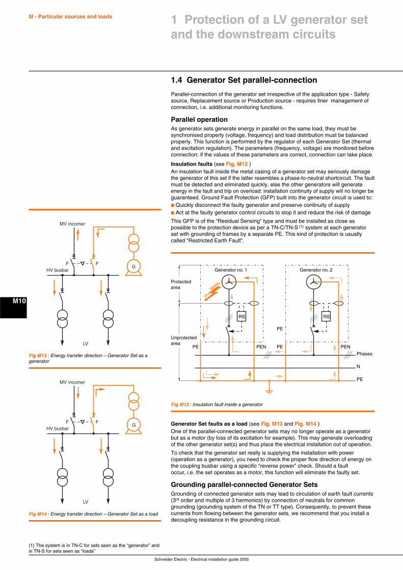
Schneider Electric - Electrical installation guide 2005
M - Particular sources and loads
M10
1 Protection of a LV generator setand the downstream circuits
1.4 Generator Set parallel-connection
Parallel-connection of the generator set irrespective of the application type - Safetysource, Replacement source or Production source - requires finer management ofconnection, i.e. additional monitoring functions.
Parallel operationAs generator sets generate energy in parallel on the same load, they must besynchronised properly (voltage, frequency) and load distribution must be balancedproperly. This function is performed by the regulator of each Generator Set (thermaland excitation regulation). The parameters (frequency, voltage) are monitored beforeconnection: if the values of these parameters are correct, connection can take place.
Insulation faults (see Fig. M12 )An insulation fault inside the metal casing of a generator set may seriously damagethe generator of this set if the latter resembles a phase-to-neutral shortcircuit. The faultmust be detected and eliminated quickly, else the other generators will generateenergy in the fault and trip on overload: installation continuity of supply will no longer beguaranteed. Ground Fault Protection (GFP) built into the generator circuit is used to:c Quickly disconnect the faulty generator and preserve continuity of supplyc Act at the faulty generator control circuits to stop it and reduce the risk of damage
This GFP is of the “Residual Sensing” type and must be installed as close aspossible to the protection device as per a TN-C/TN-S (1) system at each generatorset with grounding of frames by a separate PE. This kind of protection is usuallycalled “Restricted Earth Fault”.
(1) The system is in TN-C for sets seen as the “generator” andin TN-S for sets seen as “loads”
Fig M12 : Insulation fault inside a generator
Protected area
Generator no. 1
Phases
N
PE
PENPEN PE
PE
PE
Generator no. 2
Unprotected area
RS RS
Generator Set faults as a load (see Fig. M13 and Fig. M14 )One of the parallel-connected generator sets may no longer operate as a generatorbut as a motor (by loss of its excitation for example). This may generate overloadingof the other generator set(s) and thus place the electrical installation out of operation.
To check that the generator set really is supplying the installation with power(operation as a generator), you need to check the proper flow direction of energy onthe coupling busbar using a specific “reverse power” check. Should a faultoccur, i.e. the set operates as a motor, this function will eliminate the faulty set.
Grounding parallel-connected Generator SetsGrounding of connected generator sets may lead to circulation of earth fault currents(3rd order and multiple of 3 harmonics) by connection of neutrals for commongrounding (grounding system of the TN or TT type). Consequently, to prevent thesecurrents from flowing between the generator sets, we recommend that you install adecoupling resistance in the grounding circuit.
G
MV incomer
LV
HV busbarF F
G
MV incomer
LV
HV busbarF F
Fig M13 : Energy transfer direction – Generator Set as agenerator
Fig M14 : Energy transfer direction – Generator Set as a load
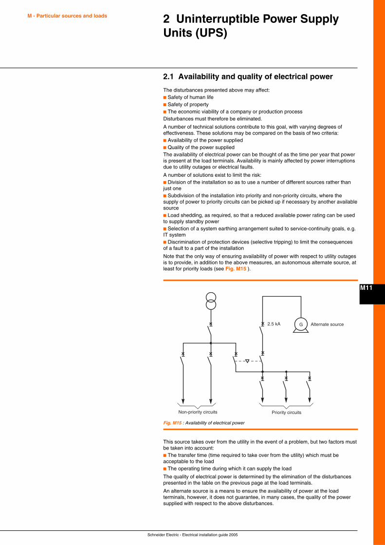
Schneider Electric - Electrical installation guide 2005
M - Particular sources and loads
M11
2 Uninterruptible Power SupplyUnits (UPS)
2.1 Availability and quality of electrical power
The disturbances presented above may affect:c Safety of human lifec Safety of propertyc The economic viability of a company or production processDisturbances must therefore be eliminated.
A number of technical solutions contribute to this goal, with varying degrees ofeffectiveness. These solutions may be compared on the basis of two criteria:c Availability of the power suppliedc Quality of the power suppliedThe availability of electrical power can be thought of as the time per year that poweris present at the load terminals. Availability is mainly affected by power interruptionsdue to utility outages or electrical faults.
A number of solutions exist to limit the risk:c Division of the installation so as to use a number of different sources rather thanjust onec Subdivision of the installation into priority and non-priority circuits, where thesupply of power to priority circuits can be picked up if necessary by another availablesourcec Load shedding, as required, so that a reduced available power rating can be usedto supply standby powerc Selection of a system earthing arrangement suited to service-continuity goals, e.g.IT systemc Discrimination of protection devices (selective tripping) to limit the consequencesof a fault to a part of the installation
Note that the only way of ensuring availability of power with respect to utility outagesis to provide, in addition to the above measures, an autonomous alternate source, atleast for priority loads (see Fig. M15 ).
Fig. M15 : Availability of electrical power
Priority circuitsNon-priority circuits
Alternate source2.5 kA G
This source takes over from the utility in the event of a problem, but two factors mustbe taken into account:c The transfer time (time required to take over from the utility) which must beacceptable to the loadc The operating time during which it can supply the load
The quality of electrical power is determined by the elimination of the disturbancespresented in the table on the previous page at the load terminals.
An alternate source is a means to ensure the availability of power at the loadterminals, however, it does not guarantee, in many cases, the quality of the powersupplied with respect to the above disturbances.
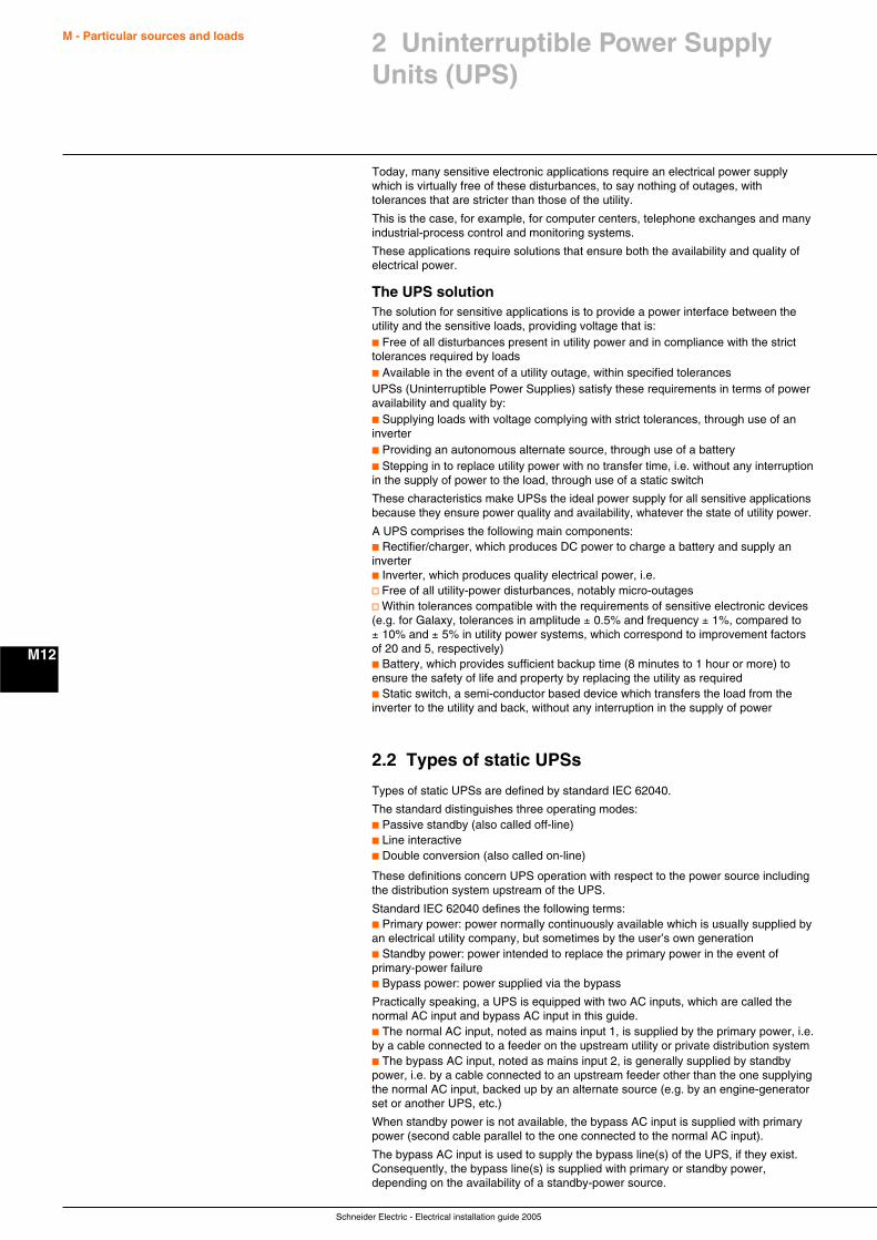
Schneider Electric - Electrical installation guide 2005
M - Particular sources and loads
M12
Today, many sensitive electronic applications require an electrical power supplywhich is virtually free of these disturbances, to say nothing of outages, withtolerances that are stricter than those of the utility.
This is the case, for example, for computer centers, telephone exchanges and manyindustrial-process control and monitoring systems.
These applications require solutions that ensure both the availability and quality ofelectrical power.
The UPS solutionThe solution for sensitive applications is to provide a power interface between theutility and the sensitive loads, providing voltage that is:c Free of all disturbances present in utility power and in compliance with the stricttolerances required by loadsc Available in the event of a utility outage, within specified tolerancesUPSs (Uninterruptible Power Supplies) satisfy these requirements in terms of poweravailability and quality by:c Supplying loads with voltage complying with strict tolerances, through use of aninverterc Providing an autonomous alternate source, through use of a batteryc Stepping in to replace utility power with no transfer time, i.e. without any interruptionin the supply of power to the load, through use of a static switch
These characteristics make UPSs the ideal power supply for all sensitive applicationsbecause they ensure power quality and availability, whatever the state of utility power.
A UPS comprises the following main components:c Rectifier/charger, which produces DC power to charge a battery and supply aninverterc Inverter, which produces quality electrical power, i.e.v Free of all utility-power disturbances, notably micro-outagesv Within tolerances compatible with the requirements of sensitive electronic devices(e.g. for Galaxy, tolerances in amplitude ± 0.5% and frequency ± 1%, compared to± 10% and ± 5% in utility power systems, which correspond to improvement factorsof 20 and 5, respectively)c Battery, which provides sufficient backup time (8 minutes to 1 hour or more) toensure the safety of life and property by replacing the utility as requiredc Static switch, a semi-conductor based device which transfers the load from theinverter to the utility and back, without any interruption in the supply of power
2.2 Types of static UPSs
Types of static UPSs are defined by standard IEC 62040.
The standard distinguishes three operating modes:c Passive standby (also called off-line)c Line interactivec Double conversion (also called on-line)
These definitions concern UPS operation with respect to the power source includingthe distribution system upstream of the UPS.
Standard IEC 62040 defines the following terms:c Primary power: power normally continuously available which is usually supplied byan electrical utility company, but sometimes by the user’s own generationc Standby power: power intended to replace the primary power in the event ofprimary-power failurec Bypass power: power supplied via the bypass
Practically speaking, a UPS is equipped with two AC inputs, which are called thenormal AC input and bypass AC input in this guide.c The normal AC input, noted as mains input 1, is supplied by the primary power, i.e.by a cable connected to a feeder on the upstream utility or private distribution systemc The bypass AC input, noted as mains input 2, is generally supplied by standbypower, i.e. by a cable connected to an upstream feeder other than the one supplyingthe normal AC input, backed up by an alternate source (e.g. by an engine-generatorset or another UPS, etc.)
When standby power is not available, the bypass AC input is supplied with primarypower (second cable parallel to the one connected to the normal AC input).
The bypass AC input is used to supply the bypass line(s) of the UPS, if they exist.Consequently, the bypass line(s) is supplied with primary or standby power,depending on the availability of a standby-power source.
2 Uninterruptible Power SupplyUnits (UPS)
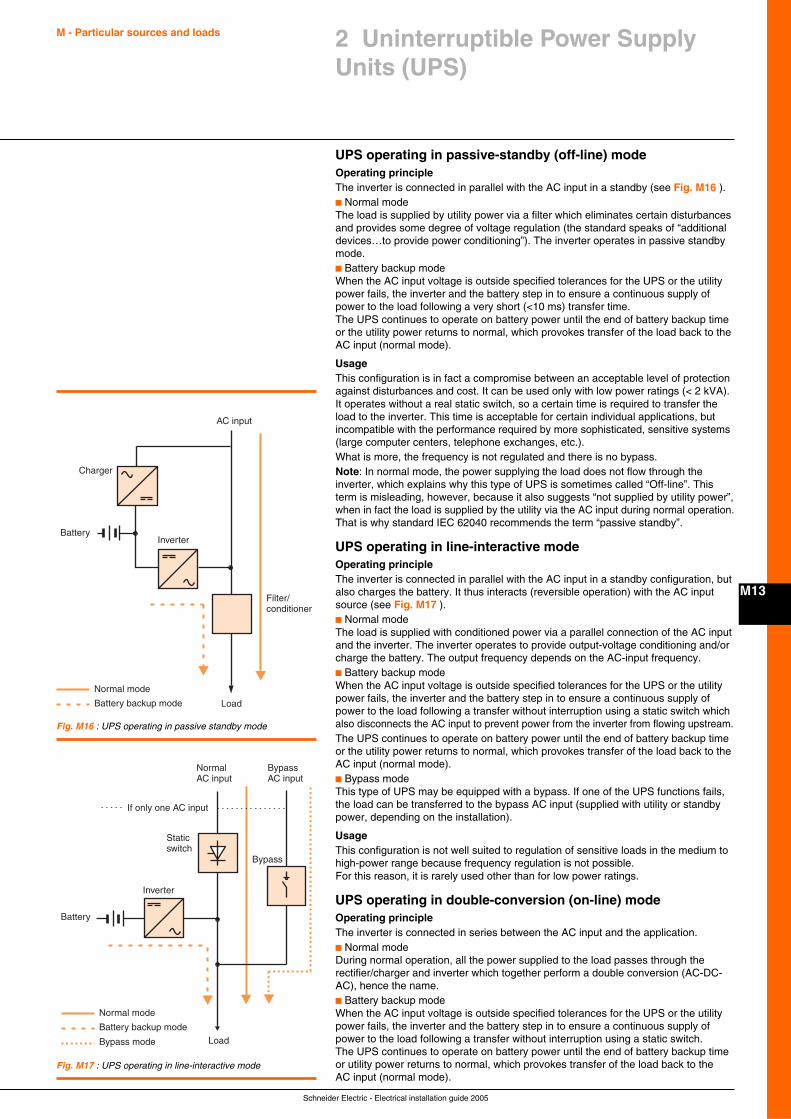
Schneider Electric - Electrical installation guide 2005
M - Particular sources and loads
M13
2 Uninterruptible Power SupplyUnits (UPS)
UPS operating in passive-standby (off-line) modeOperating principleThe inverter is connected in parallel with the AC input in a standby (see Fig. M16 ).c Normal modeThe load is supplied by utility power via a filter which eliminates certain disturbancesand provides some degree of voltage regulation (the standard speaks of “additionaldevices…to provide power conditioning”). The inverter operates in passive standbymode.c Battery backup modeWhen the AC input voltage is outside specified tolerances for the UPS or the utilitypower fails, the inverter and the battery step in to ensure a continuous supply ofpower to the load following a very short (<10 ms) transfer time.The UPS continues to operate on battery power until the end of battery backup timeor the utility power returns to normal, which provokes transfer of the load back to theAC input (normal mode).
UsageThis configuration is in fact a compromise between an acceptable level of protectionagainst disturbances and cost. It can be used only with low power ratings (< 2 kVA).It operates without a real static switch, so a certain time is required to transfer theload to the inverter. This time is acceptable for certain individual applications, butincompatible with the performance required by more sophisticated, sensitive systems(large computer centers, telephone exchanges, etc.).What is more, the frequency is not regulated and there is no bypass.Note: In normal mode, the power supplying the load does not flow through theinverter, which explains why this type of UPS is sometimes called “Off-line”. Thisterm is misleading, however, because it also suggests “not supplied by utility power”,when in fact the load is supplied by the utility via the AC input during normal operation.That is why standard IEC 62040 recommends the term “passive standby”.
UPS operating in line-interactive modeOperating principleThe inverter is connected in parallel with the AC input in a standby configuration, butalso charges the battery. It thus interacts (reversible operation) with the AC inputsource (see Fig. M17 ).c Normal modeThe load is supplied with conditioned power via a parallel connection of the AC inputand the inverter. The inverter operates to provide output-voltage conditioning and/orcharge the battery. The output frequency depends on the AC-input frequency.c Battery backup modeWhen the AC input voltage is outside specified tolerances for the UPS or the utilitypower fails, the inverter and the battery step in to ensure a continuous supply ofpower to the load following a transfer without interruption using a static switch whichalso disconnects the AC input to prevent power from the inverter from flowing upstream.The UPS continues to operate on battery power until the end of battery backup timeor the utility power returns to normal, which provokes transfer of the load back to theAC input (normal mode).c Bypass modeThis type of UPS may be equipped with a bypass. If one of the UPS functions fails,the load can be transferred to the bypass AC input (supplied with utility or standbypower, depending on the installation).
UsageThis configuration is not well suited to regulation of sensitive loads in the medium tohigh-power range because frequency regulation is not possible.For this reason, it is rarely used other than for low power ratings.
UPS operating in double-conversion (on-line) modeOperating principleThe inverter is connected in series between the AC input and the application.c Normal modeDuring normal operation, all the power supplied to the load passes through therectifier/charger and inverter which together perform a double conversion (AC-DC-AC), hence the name.c Battery backup modeWhen the AC input voltage is outside specified tolerances for the UPS or the utilitypower fails, the inverter and the battery step in to ensure a continuous supply ofpower to the load following a transfer without interruption using a static switch.The UPS continues to operate on battery power until the end of battery backup timeor utility power returns to normal, which provokes transfer of the load back to theAC input (normal mode).
Normal mode
Battery
Charger
Inverter
AC input
Filter/conditioner
LoadBattery backup mode
Fig. M17 : UPS operating in line-interactive mode
Fig. M16 : UPS operating in passive standby mode
Normal mode
Battery
If only one AC input
Inverter
NormalAC input
BypassAC input
Bypass
Staticswitch
LoadBattery backup mode
Bypass mode
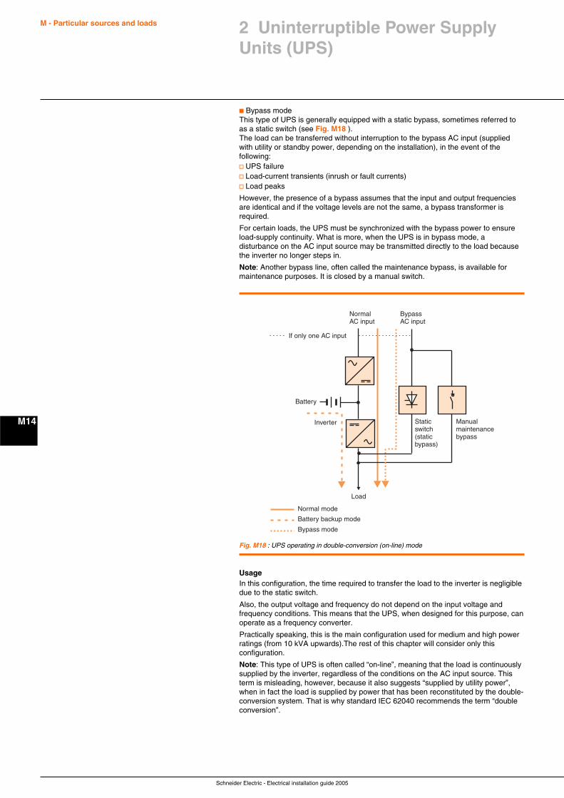
Schneider Electric - Electrical installation guide 2005
M - Particular sources and loads
M14
c Bypass modeThis type of UPS is generally equipped with a static bypass, sometimes referred toas a static switch (see Fig. M18 ).The load can be transferred without interruption to the bypass AC input (suppliedwith utility or standby power, depending on the installation), in the event of thefollowing:v UPS failurev Load-current transients (inrush or fault currents)v Load peaks
However, the presence of a bypass assumes that the input and output frequenciesare identical and if the voltage levels are not the same, a bypass transformer isrequired.
For certain loads, the UPS must be synchronized with the bypass power to ensureload-supply continuity. What is more, when the UPS is in bypass mode, adisturbance on the AC input source may be transmitted directly to the load becausethe inverter no longer steps in.
Note: Another bypass line, often called the maintenance bypass, is available formaintenance purposes. It is closed by a manual switch.
Normal mode
Battery
If only one AC input
Inverter
NormalAC input
BypassAC input
Staticswitch(staticbypass)
Manualmaintenancebypass
Load
Battery backup mode
Bypass mode
Fig. M18 : UPS operating in double-conversion (on-line) mode
UsageIn this configuration, the time required to transfer the load to the inverter is negligibledue to the static switch.
Also, the output voltage and frequency do not depend on the input voltage andfrequency conditions. This means that the UPS, when designed for this purpose, canoperate as a frequency converter.
Practically speaking, this is the main configuration used for medium and high powerratings (from 10 kVA upwards).The rest of this chapter will consider only thisconfiguration.
Note: This type of UPS is often called “on-line”, meaning that the load is continuouslysupplied by the inverter, regardless of the conditions on the AC input source. Thisterm is misleading, however, because it also suggests “supplied by utility power”,when in fact the load is supplied by power that has been reconstituted by the double-conversion system. That is why standard IEC 62040 recommends the term “doubleconversion”.
2 Uninterruptible Power SupplyUnits (UPS)

Schneider Electric - Electrical installation guide 2005
M - Particular sources and loads
M15
2 Uninterruptible Power SupplyUnits (UPS)
2.3 Batteries
Selection of battery typeA battery is made up of interconnected cells which may be vented or of therecombination type.
There are two main families of batteries:c Nickel-cadmium batteriesc Lead-acid batteriesc Vented cells (lead-antimony): They are equipped with ports tov Release to the atmosphere the oxygen and hydrogen produced during the differentchemical reactionsv Top off the electrolyte by adding distilled or demineralized waterc Recombination cells (lead, pure lead, lead-tin batteries): The gas recombinationrate is at least 95% and they therefore do not require water to be added duringservice lifeBy extension, reference will be made to vented or recombination batteries(recombination batteries are also often called “sealed” batteries).
The main types of batteries used in conjunction with UPSs are:c Sealed lead-acid batteries, used 95% of the time because they are easy tomaintain and do not require a special roomc Vented lead-acid batteriesc Vented nickel-cadmium batteries
The above three types of batteries may be proposed, depending on economicfactors and the operating requirements of the installation, with all the availableservice-life durations.
Capacity levels and backup times may be adapted to suit the user’s needs.The proposed batteries are also perfectly suited to UPS applications in that they arethe result of collaboration with leading battery manufacturers.
Selection of back up timeSelection depends on:c The average duration of power-system failuresc Any available long-lasting standby power (engine-generator set, etc.)c The type of application
The typical range generally proposed is:c Standard backup times of 10, 15 or 30 minutesc Custom backup times
The following general rules apply:c Computer applicationsBattery backup time must be sufficient to cover file-saving and system-shutdownprocedures required to ensure a controlled shutdown of the computer system.Generally speaking, the computer department determines the necessary backuptime, depending on its specific requirements.c Industrial processesThe backup time calculation should take into account the economic cost incurred byan interruption in the process and the time required to restart.
Selection tableFigure M19 next page sums up the main characteristics of the various types ofbatteries.Increasingly, recombination batteries would seem to be the market choice for thefollowing reasons:c No maintenancec Easy implementationc Installation in all types of rooms (computer rooms, technical rooms not specificallyintended for batteries, etc.)
In certain cases, however, vented batteries are preferred, notably for:c Long service lifec Long backup timesc High power ratings
Vented batteries must be installed in special rooms complying with preciseregulations and require appropriate maintenance.
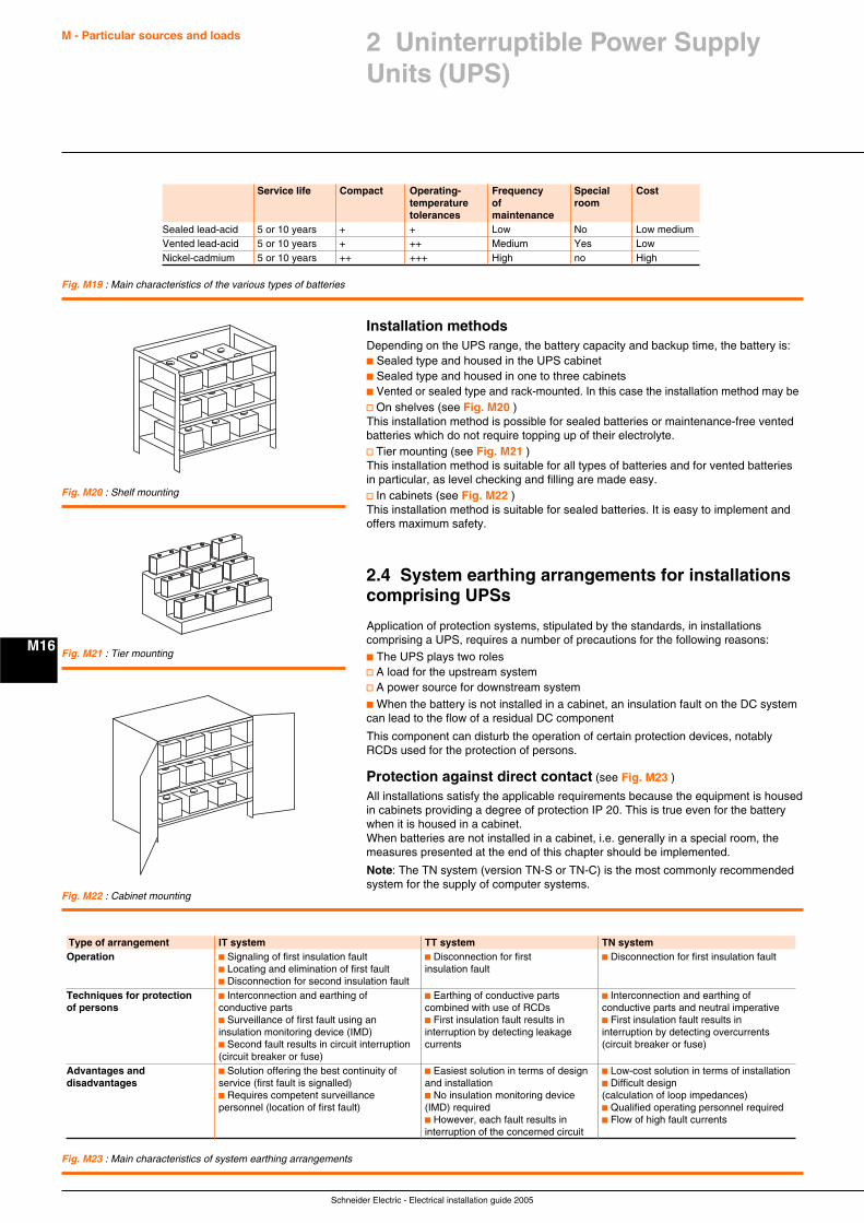
Schneider Electric - Electrical installation guide 2005
M - Particular sources and loads
M16
Installation methodsDepending on the UPS range, the battery capacity and backup time, the battery is:c Sealed type and housed in the UPS cabinetc Sealed type and housed in one to three cabinetsc Vented or sealed type and rack-mounted. In this case the installation method may bev On shelves (see Fig. M20 )This installation method is possible for sealed batteries or maintenance-free ventedbatteries which do not require topping up of their electrolyte.v Tier mounting (see Fig. M21 )This installation method is suitable for all types of batteries and for vented batteriesin particular, as level checking and filling are made easy.v In cabinets (see Fig. M22 )This installation method is suitable for sealed batteries. It is easy to implement andoffers maximum safety.
2.4 System earthing arrangements for installationscomprising UPSs
Application of protection systems, stipulated by the standards, in installationscomprising a UPS, requires a number of precautions for the following reasons:
c The UPS plays two rolesv A load for the upstream systemv A power source for downstream system
c When the battery is not installed in a cabinet, an insulation fault on the DC systemcan lead to the flow of a residual DC component
This component can disturb the operation of certain protection devices, notablyRCDs used for the protection of persons.
Protection against direct contact (see Fig. M23 )
All installations satisfy the applicable requirements because the equipment is housedin cabinets providing a degree of protection IP 20. This is true even for the batterywhen it is housed in a cabinet.When batteries are not installed in a cabinet, i.e. generally in a special room, themeasures presented at the end of this chapter should be implemented.
Note: The TN system (version TN-S or TN-C) is the most commonly recommendedsystem for the supply of computer systems.
Fig. M19 : Main characteristics of the various types of batteries
Fig. M20 : Shelf mounting
Fig. M21 : Tier mounting
Fig. M22 : Cabinet mounting
Fig. M23 : Main characteristics of system earthing arrangements
Type of arrangement IT system TT system TN systemOperation c Signaling of first insulation fault c Disconnection for first c Disconnection for first insulation fault
c Locating and elimination of first fault insulation faultc Disconnection for second insulation fault
Techniques for protection c Interconnection and earthing of c Earthing of conductive parts c Interconnection and earthing ofof persons conductive parts combined with use of RCDs conductive parts and neutral imperative
c Surveillance of first fault using an c First insulation fault results in c First insulation fault results ininsulation monitoring device (IMD) interruption by detecting leakage interruption by detecting overcurrentsc Second fault results in circuit interruption currents (circuit breaker or fuse)(circuit breaker or fuse)
Advantages and c Solution offering the best continuity of c Easiest solution in terms of design c Low-cost solution in terms of installationdisadvantages service (first fault is signalled) and installation c Difficult design
c Requires competent surveillance c No insulation monitoring device (calculation of loop impedances)personnel (location of first fault) (IMD) required c Qualified operating personnel required
c However, each fault results in c Flow of high fault currentsinterruption of the concerned circuit
Service life Compact Operating- Frequency Special Costtemperature of roomtolerances maintenance
Sealed lead-acid 5 or 10 years + + Low No Low mediumVented lead-acid 5 or 10 years + ++ Medium Yes LowNickel-cadmium 5 or 10 years ++ +++ High no High
2 Uninterruptible Power SupplyUnits (UPS)
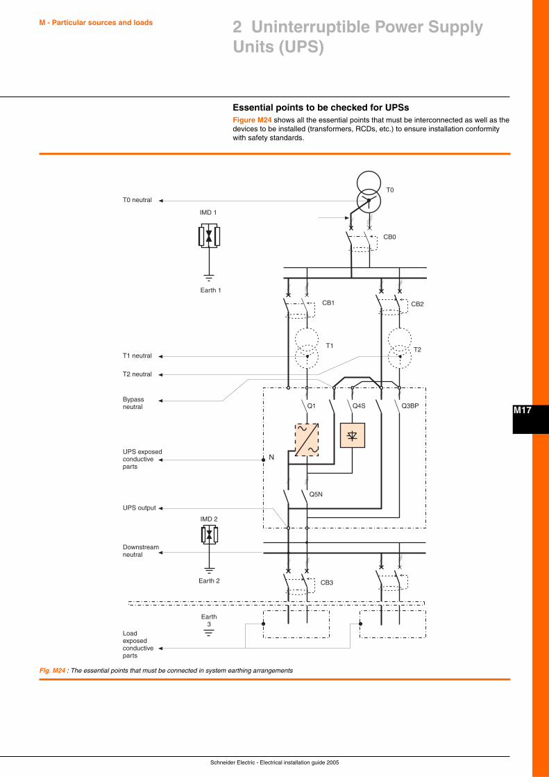
Schneider Electric - Electrical installation guide 2005
M - Particular sources and loads
M17
2 Uninterruptible Power SupplyUnits (UPS)
Essential points to be checked for UPSsFigure M24 shows all the essential points that must be interconnected as well as thedevices to be installed (transformers, RCDs, etc.) to ensure installation conformitywith safety standards.
Fig. M24 : The essential points that must be connected in system earthing arrangements
N
CB0
T0
IMD 1
IMD 2
Earth 2
Earth 3
Earth 1
CB1
CB3
T1T2
CB2
Q1 Q4S
Q5N
Q3BP
T0 neutral
T1 neutral
T2 neutral
Bypassneutral
UPS exposedconductiveparts
UPS output
Downstreamneutral
Loadexposedconductiveparts
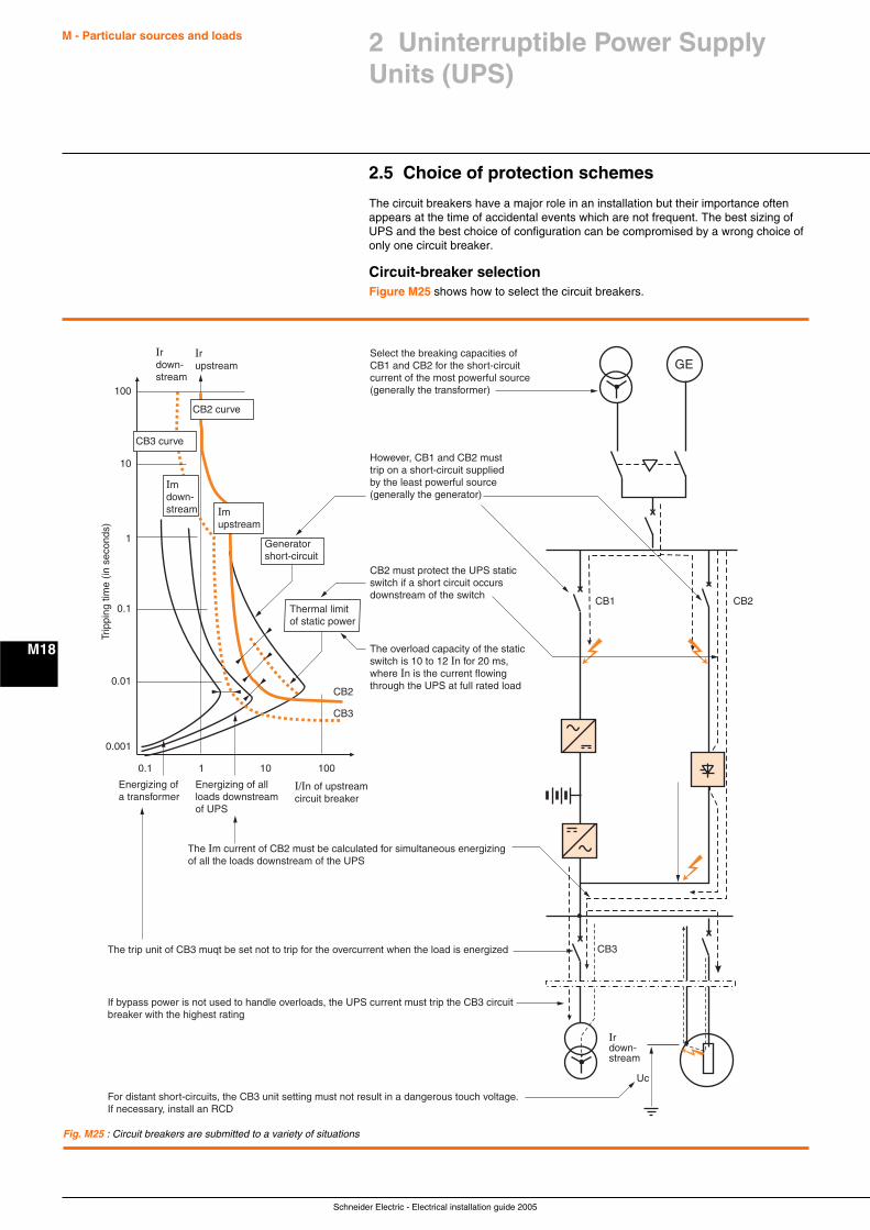
Schneider Electric - Electrical installation guide 2005
M - Particular sources and loads
M18
2.5 Choice of protection schemes
The circuit breakers have a major role in an installation but their importance oftenappears at the time of accidental events which are not frequent. The best sizing ofUPS and the best choice of configuration can be compromised by a wrong choice ofonly one circuit breaker.
Circuit-breaker selectionFigure M25 shows how to select the circuit breakers.
Fig. M25 : Circuit breakers are submitted to a variety of situations
CB1 CB2
CB3
CB3
CB2
1010.1 100
0.1
0.01
0.001
1
10
100
Uc
GE
Ir down-stream
Select the breaking capacities of CB1 and CB2 for the short-circuit current of the most powerful source (generally the transformer)
However, CB1 and CB2 must trip on a short-circuit supplied by the least powerful source (generally the generator)
CB2 must protect the UPS static switch if a short circuit occurs downstream of the switch
The Im current of CB2 must be calculated for simultaneous energizing of all the loads downstream of the UPS
If bypass power is not used to handle overloads, the UPS current must trip the CB3 circuit breaker with the highest rating
The trip unit of CB3 muqt be set not to trip for the overcurrent when the load is energized
For distant short-circuits, the CB3 unit setting must not result in a dangerous touch voltage. If necessary, install an RCD
The overload capacity of the static switch is 10 to 12 In for 20 ms, where In is the current flowing through the UPS at full rated load
Trip
ping
tim
e (in
sec
onds
)
Energizing of a transformer
Energizing of all loads downstream of UPS
I/In of upstream circuit breaker
Imupstream
Imdown-stream
Irupstream
Irdown-stream
CB2 curve
CB3 curve
Generatorshort-circuit
Thermal limitof static power
2 Uninterruptible Power SupplyUnits (UPS)
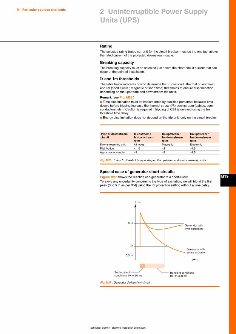
Schneider Electric - Electrical installation guide 2005
M - Particular sources and loads
M19
2 Uninterruptible Power SupplyUnits (UPS)
RatingThe selected rating (rated current) for the circuit breaker must be the one just abovethe rated current of the protected downstream cable.
Breaking capacityThe breaking capacity must be selected just above the short-circuit current that canoccur at the point of installation.
Ir and Im thresholdsThe table below indicates how to determine the Ir (overload ; thermal or longtime)and Im (short circuit ; magnetic or short time) thresholds to ensure discrimination,depending on the upstream and downstream trip units.
Remark (see Fig. M26 )c Time discrimination must be implemented by qualified personnel because timedelays before tripping increase the thermal stress (I2t) downstream (cables, semi-conductors, etc.). Caution is required if tripping of CB2 is delayed using the Imthreshold time delayc Energy discrimination does not depend on the trip unit, only on the circuit breaker
Fig. M26 : Ir and Im thresholds depending on the upstream and downstream trip units
Type of downstream Ir upstream / Im upstream / Im upstream /circuit Ir downstream Im downstream Im downstream
ratio ratio ratioDownstream trip unit All types Magnetic ElectronicDistribution > 1.6 >2 >1.5Asynchronous motor >3 >2 >1.5
Special case of generator short-circuitsFigure M27 shows the reaction of a generator to a short-circuit.To avoid any uncertainty concerning the type of excitation, we will trip at the firstpeak (3 to 5 In as per X”d) using the Im protection setting without a time delay.
Fig. M27 : Generator during short-circuit
Irms
t
3 In
In
0.3 In
Subtransient conditions 10 to 20 ms
Transient conditions 100 to 300 ms
Generator withover-excitation
Generator with series excitation
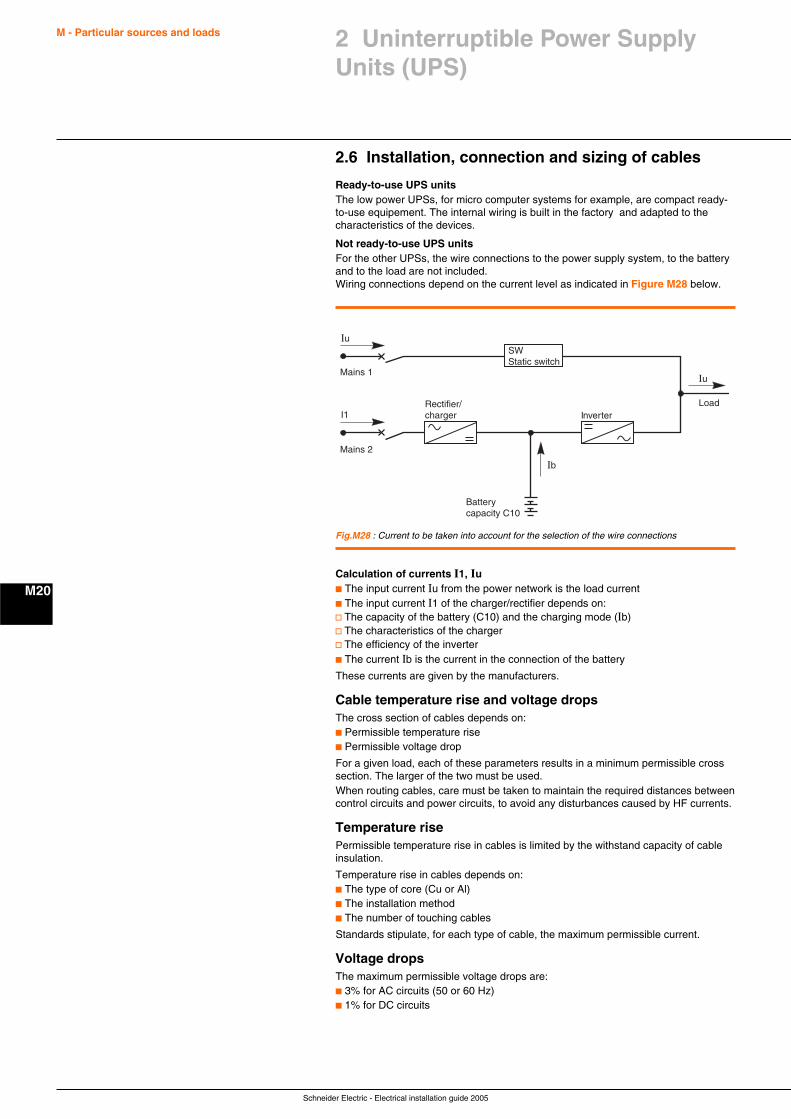
Schneider Electric - Electrical installation guide 2005
M - Particular sources and loads
M20
2.6 Installation, connection and sizing of cables
Ready-to-use UPS unitsThe low power UPSs, for micro computer systems for example, are compact ready-to-use equipement. The internal wiring is built in the factory and adapted to thecharacteristics of the devices.
Not ready-to-use UPS unitsFor the other UPSs, the wire connections to the power supply system, to the batteryand to the load are not included.Wiring connections depend on the current level as indicated in Figure M28 below.
Fig.M28 : Current to be taken into account for the selection of the wire connections
SWStatic switch
Rectifier/charger
Batterycapacity C10
Ib
InverterLoad
Mains 1
Mains 2
Iu
I1
Iu
Calculation of currents I1, Iuc The input current Iu from the power network is the load currentc The input current I1 of the charger/rectifier depends on:v The capacity of the battery (C10) and the charging mode (Ib)v The characteristics of the chargerv The efficiency of the inverterc The current Ib is the current in the connection of the battery
These currents are given by the manufacturers.
Cable temperature rise and voltage dropsThe cross section of cables depends on:c Permissible temperature risec Permissible voltage drop
For a given load, each of these parameters results in a minimum permissible crosssection. The larger of the two must be used.When routing cables, care must be taken to maintain the required distances betweencontrol circuits and power circuits, to avoid any disturbances caused by HF currents.
Temperature risePermissible temperature rise in cables is limited by the withstand capacity of cableinsulation.
Temperature rise in cables depends on:c The type of core (Cu or Al)c The installation methodc The number of touching cables
Standards stipulate, for each type of cable, the maximum permissible current.
Voltage dropsThe maximum permissible voltage drops are:c 3% for AC circuits (50 or 60 Hz)c 1% for DC circuits
2 Uninterruptible Power SupplyUnits (UPS)
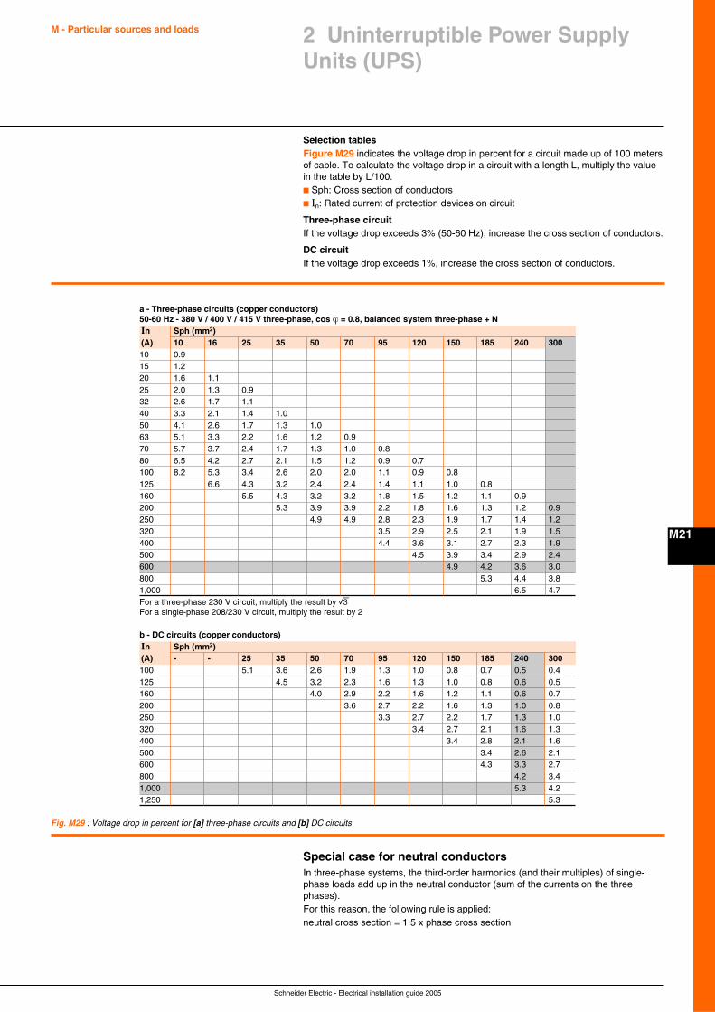
Schneider Electric - Electrical installation guide 2005
M - Particular sources and loads
M21
2 Uninterruptible Power SupplyUnits (UPS)
Selection tablesFigure M29 indicates the voltage drop in percent for a circuit made up of 100 metersof cable. To calculate the voltage drop in a circuit with a length L, multiply the valuein the table by L/100.c Sph: Cross section of conductorsc In: Rated current of protection devices on circuit
Three-phase circuitIf the voltage drop exceeds 3% (50-60 Hz), increase the cross section of conductors.
DC circuitIf the voltage drop exceeds 1%, increase the cross section of conductors.
a - Three-phase circuits (copper conductors)50-60 Hz - 380 V / 400 V / 415 V three-phase, cos ϕ = 0.8, balanced system three-phase + NIn Sph (mm2)(A) 10 16 25 35 50 70 95 120 150 185 240 30010 0.915 1.220 1.6 1.125 2.0 1.3 0.932 2.6 1.7 1.140 3.3 2.1 1.4 1.050 4.1 2.6 1.7 1.3 1.063 5.1 3.3 2.2 1.6 1.2 0.970 5.7 3.7 2.4 1.7 1.3 1.0 0.880 6.5 4.2 2.7 2.1 1.5 1.2 0.9 0.7100 8.2 5.3 3.4 2.6 2.0 2.0 1.1 0.9 0.8125 6.6 4.3 3.2 2.4 2.4 1.4 1.1 1.0 0.8160 5.5 4.3 3.2 3.2 1.8 1.5 1.2 1.1 0.9200 5.3 3.9 3.9 2.2 1.8 1.6 1.3 1.2 0.9250 4.9 4.9 2.8 2.3 1.9 1.7 1.4 1.2320 3.5 2.9 2.5 2.1 1.9 1.5400 4.4 3.6 3.1 2.7 2.3 1.9500 4.5 3.9 3.4 2.9 2.4600 4.9 4.2 3.6 3.0800 5.3 4.4 3.81,000 6.5 4.7For a three-phase 230 V circuit, multiply the result by eFor a single-phase 208/230 V circuit, multiply the result by 2
b - DC circuits (copper conductors)In Sph (mm2)(A) - - 25 35 50 70 95 120 150 185 240 300100 5.1 3.6 2.6 1.9 1.3 1.0 0.8 0.7 0.5 0.4125 4.5 3.2 2.3 1.6 1.3 1.0 0.8 0.6 0.5160 4.0 2.9 2.2 1.6 1.2 1.1 0.6 0.7200 3.6 2.7 2.2 1.6 1.3 1.0 0.8250 3.3 2.7 2.2 1.7 1.3 1.0320 3.4 2.7 2.1 1.6 1.3400 3.4 2.8 2.1 1.6500 3.4 2.6 2.1600 4.3 3.3 2.7800 4.2 3.41,000 5.3 4.21,250 5.3
Fig. M29 : Voltage drop in percent for [a] three-phase circuits and [b] DC circuits
Special case for neutral conductorsIn three-phase systems, the third-order harmonics (and their multiples) of single-phase loads add up in the neutral conductor (sum of the currents on the threephases).For this reason, the following rule is applied:neutral cross section = 1.5 x phase cross section
Schneider Electric - Electrical installation guide 2005
M - Particular sources and loads
M22
ExampleConsider a 70-meter 400 V three-phase circuit, with copper conductors and a ratedcurrent of 600 A.Standard IEC 364 indicates, depending on the installation method and the load, aminimum cross section.We shall assume that the minimum cross section is 95 mm2.It is first necessary to check that the voltage drop does not exceed 3%.The table for three-phase circuits on the following page indicates, for a 600 A currentflowing in a 300 mm2 cable, a voltage drop of 3% for 100 meters of cable, i.e. for70 meters:
3 x 70
1002.1%=
Therefore less than 3%
A identical calculation can be run for a DC current of 1,000 A.In a ten-meter cable, the voltage drop for 100 meters of 240 mm2 cable is 5.3%, i.e.for ten meters:
5. x 10100
0.53%3 =
Therefore less than 3%
2.7 The UPSs and their environment
The UPSs can communicate with electrical and computing environment. They canreceive some data and provide information on their operation in order:
c To optimize the protectionFor example, the UPS provides essential information on operating status to thecomputer system (load on inverter, load on static bypass, load on batterie, lowbattery warning)
c To remotly controlThe UPS provides measurement and operating status information to inform andallow operators to take specific actions
c To manage the installationThe operator has a building and energy management system which allow to obtainand save information from UPSs, to provide alarms and events and to take actions.
This evolution towards compatibilty between computer equipment and UPSs has theeffect to incorporate new built-in UPS functions.
2.8 Complementary equipment
TransformersA two-winding transformer included on the upstream side of the static contactor ofcircuit 2 allows:c A change of voltage level when the power network voltage is different to that of theloadc A change of system of earthing between the networks
Moreover, such a transformer :c Reduces the short-circuit current level on the secondary, (i.e load) side comparedwith that on the power network sidec Prevents third harmonic currents which may be present on the secondary sidefrom passing into the power-system network, providing that the primary winding isconnected in delta.
Anti-harmonic filterThe UPS system includes a battery charger which is controlled by thyristors ortransistors. The resulting regularly-chopped current cycles “generate” harmoniccomponents in the power-supply network.
These indesirable components are filtered at the input of the rectifier and for mostcases this reduces the harmonic current level sufficiently for all practical purposes.In certain specific cases however, notably in very large installations, an additionalfilter circuit may be necessary.
2 Uninterruptible Power SupplyUnits (UPS)
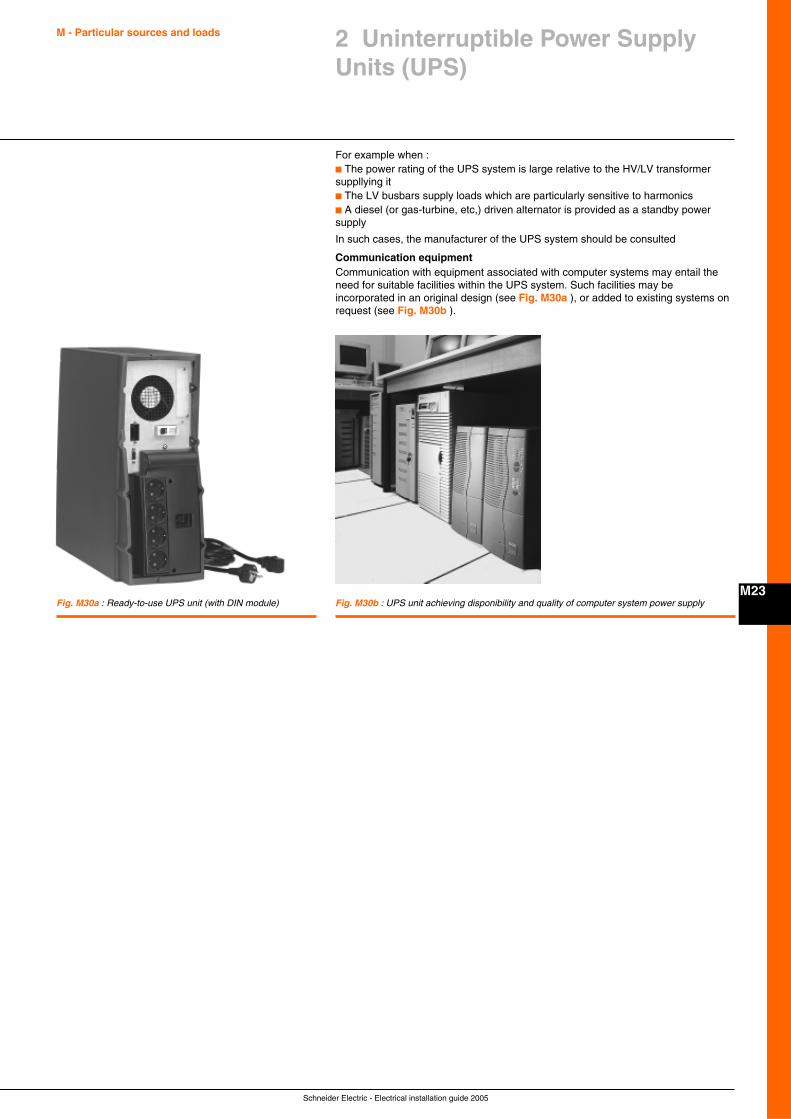
Schneider Electric - Electrical installation guide 2005
M - Particular sources and loads
M23
2 Uninterruptible Power SupplyUnits (UPS)
For example when :c The power rating of the UPS system is large relative to the HV/LV transformersuppllying itc The LV busbars supply loads which are particularly sensitive to harmonicsc A diesel (or gas-turbine, etc,) driven alternator is provided as a standby powersupply
In such cases, the manufacturer of the UPS system should be consulted
Communication equipmentCommunication with equipment associated with computer systems may entail theneed for suitable facilities within the UPS system. Such facilities may beincorporated in an original design (see Fig. M30a ), or added to existing systems onrequest (see Fig. M30b ).
Fig. M30b : UPS unit achieving disponibility and quality of computer system power supplyFig. M30a : Ready-to-use UPS unit (with DIN module)
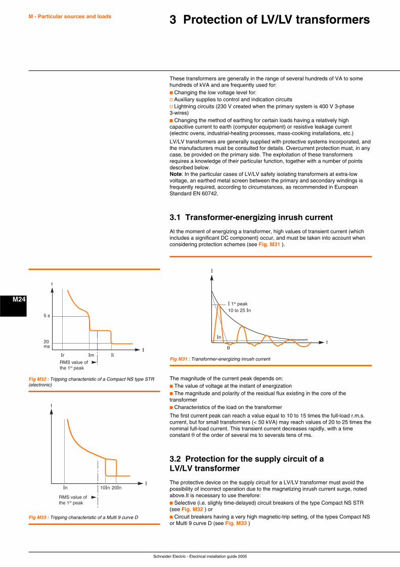
Schneider Electric - Electrical installation guide 2005
M - Particular sources and loads
M24
3 Protection of LV/LV transformers
These transformers are generally in the range of several hundreds of VA to somehundreds of kVA and are frequently used for:c Changing the low voltage level for:v Auxiliary supplies to control and indication circuitsv Lightning circuits (230 V created when the primary system is 400 V 3-phase3-wires)c Changing the method of earthing for certain loads having a relatively highcapacitive current to earth (computer equipment) or resistive leakage current(electric ovens, industrial-heating processes, mass-cooking installations, etc.)
LV/LV transformers are generally supplied with protective systems incorporated, andthe manufacturers must be consulted for details. Overcurrent protection must, in anycase, be provided on the primary side. The exploitation of these transformersrequires a knowledge of their particular function, together with a number of pointsdescribed below.Note: In the particular cases of LV/LV safety isolating transformers at extra-lowvoltage, an earthed metal screen between the primary and secondary windings isfrequently required, according to circumstances, as recommended in EuropeanStandard EN 60742.
3.1 Transformer-energizing inrush current
At the moment of energizing a transformer, high values of transient current (whichincludes a significant DC component) occur, and must be taken into account whenconsidering protection schemes (see Fig. M31 ).
Fig M31 : Transformer-energizing inrush current
In
I
I 1st peak10 to 25 In
t
RMS value ofthe 1st peak
t
20ms
5 s
ImI
IiIr
Fig M32 : Tripping characteristic of a Compact NS type STR(electronic)
Fig M33 : Tripping characteristic of a Multi 9 curve D
The magnitude of the current peak depends on:c The value of voltage at the instant of energizationc The magnitude and polarity of the residual flux existing in the core of thetransformerc Characteristics of the load on the transformer
The first current peak can reach a value equal to 10 to 15 times the full-load r.m.s.current, but for small transformers (< 50 kVA) may reach values of 20 to 25 times thenominal full-load current. This transient current decreases rapidly, with a timeconstant θ of the order of several ms to severals tens of ms.
3.2 Protection for the supply circuit of aLV/LV transformer
The protective device on the supply circuit for a LV/LV transformer must avoid thepossibility of incorrect operation due to the magnetizing inrush current surge, notedabove.It is necessary to use therefore:c Selective (i.e. slighly time-delayed) circuit breakers of the type Compact NS STR(see Fig. M32 ) orc Circuit breakers having a very high magnetic-trip setting, of the types Compact NSor Multi 9 curve D (see Fig. M33 )
RMS value ofthe 1st peak
In 10In 20InI
t
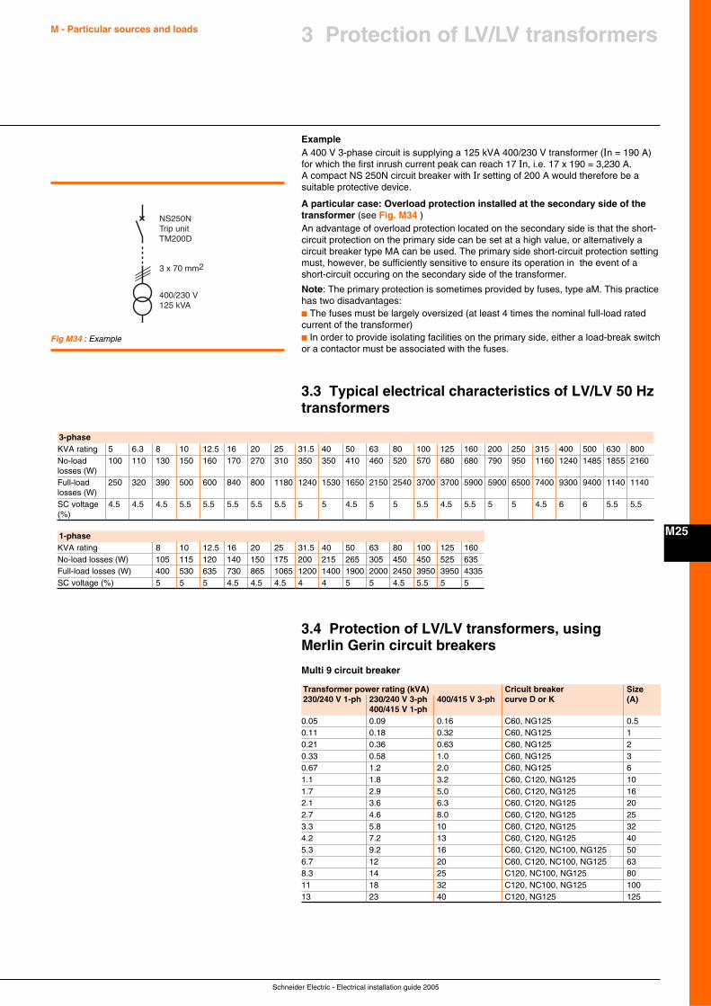
Schneider Electric - Electrical installation guide 2005
M - Particular sources and loads
M25
3 Protection of LV/LV transformers
ExampleA 400 V 3-phase circuit is supplying a 125 kVA 400/230 V transformer (In = 190 A)for which the first inrush current peak can reach 17 In, i.e. 17 x 190 = 3,230 A.A compact NS 250N circuit breaker with Ir setting of 200 A would therefore be asuitable protective device.
A particular case: Overload protection installed at the secondary side of thetransformer (see Fig. M34 )An advantage of overload protection located on the secondary side is that the short-circuit protection on the primary side can be set at a high value, or alternatively acircuit breaker type MA can be used. The primary side short-circuit protection settingmust, however, be sufficiently sensitive to ensure its operation in the event of ashort-circuit occuring on the secondary side of the transformer.
Note: The primary protection is sometimes provided by fuses, type aM. This practicehas two disadvantages:c The fuses must be largely oversized (at least 4 times the nominal full-load ratedcurrent of the transformer)c In order to provide isolating facilities on the primary side, either a load-break switchor a contactor must be associated with the fuses.
3.3 Typical electrical characteristics of LV/LV 50 Hztransformers
400/230 V125 kVA
3 x 70 mm2
NS250NTrip unitTM200D
Fig M34 : Example
3.4 Protection of LV/LV transformers, usingMerlin Gerin circuit breakers
Multi 9 circuit breaker
3-phaseKVA rating 5 6.3 8 10 12.5 16 20 25 31.5 40 50 63 80 100 125 160 200 250 315 400 500 630 800No-load 100 110 130 150 160 170 270 310 350 350 410 460 520 570 680 680 790 950 1160 1240 1485 1855 2160losses (W)Full-load 250 320 390 500 600 840 800 1180 1240 1530 1650 2150 2540 3700 3700 5900 5900 6500 7400 9300 9400 1140 1140losses (W)SC voltage 4.5 4.5 4.5 5.5 5.5 5.5 5.5 5.5 5 5 4.5 5 5 5.5 4.5 5.5 5 5 4.5 6 6 5.5 5.5(%)
1-phaseKVA rating 8 10 12.5 16 20 25 31.5 40 50 63 80 100 125 160No-load losses (W) 105 115 120 140 150 175 200 215 265 305 450 450 525 635Full-load losses (W) 400 530 635 730 865 1065 1200 1400 1900 2000 2450 3950 3950 4335SC voltage (%) 5 5 5 4.5 4.5 4.5 4 4 5 5 4.5 5.5 5 5
Transformer power rating (kVA) Cricuit breaker Size230/240 V 1-ph 230/240 V 3-ph 400/415 V 3-ph curve D or K (A)
400/415 V 1-ph0.05 0.09 0.16 C60, NG125 0.50.11 0.18 0.32 C60, NG125 10.21 0.36 0.63 C60, NG125 20.33 0.58 1.0 C60, NG125 30.67 1.2 2.0 C60, NG125 61.1 1.8 3.2 C60, C120, NG125 101.7 2.9 5.0 C60, C120, NG125 162.1 3.6 6.3 C60, C120, NG125 202.7 4.6 8.0 C60, C120, NG125 253.3 5.8 10 C60, C120, NG125 324.2 7.2 13 C60, C120, NG125 405.3 9.2 16 C60, C120, NC100, NG125 506.7 12 20 C60, C120, NC100, NG125 638.3 14 25 C120, NC100, NG125 8011 18 32 C120, NC100, NG125 10013 23 40 C120, NG125 125
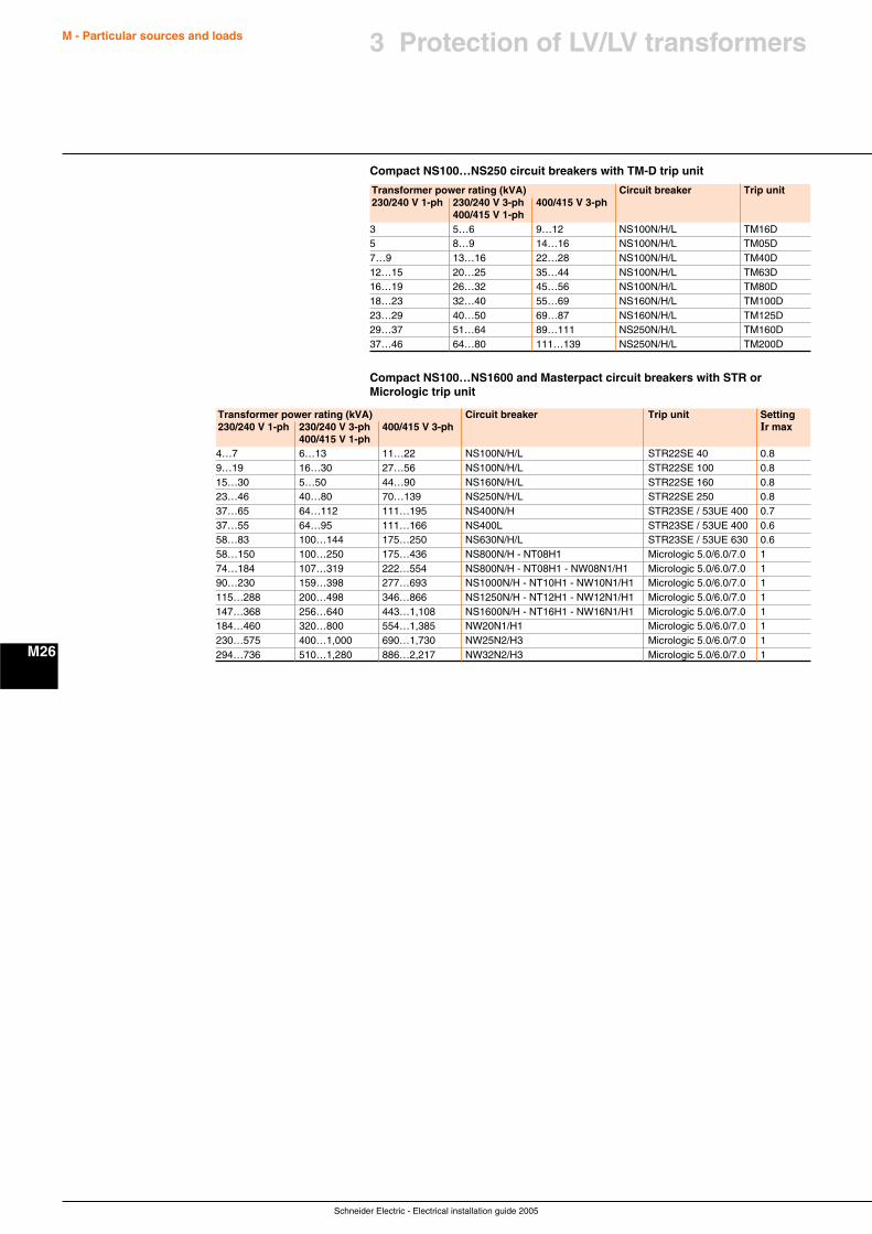
Schneider Electric - Electrical installation guide 2005
M - Particular sources and loads
M26
3 Protection of LV/LV transformers
Compact NS100…NS250 circuit breakers with TM-D trip unit
Compact NS100…NS1600 and Masterpact circuit breakers with STR orMicrologic trip unit
Transformer power rating (kVA) Circuit breaker Trip unit230/240 V 1-ph 230/240 V 3-ph 400/415 V 3-ph
400/415 V 1-ph3 5…6 9…12 NS100N/H/L TM16D5 8…9 14…16 NS100N/H/L TM05D7…9 13…16 22…28 NS100N/H/L TM40D12…15 20…25 35…44 NS100N/H/L TM63D16…19 26…32 45…56 NS100N/H/L TM80D18…23 32…40 55…69 NS160N/H/L TM100D23…29 40…50 69…87 NS160N/H/L TM125D29…37 51…64 89…111 NS250N/H/L TM160D37…46 64…80 111…139 NS250N/H/L TM200D
Transformer power rating (kVA) Circuit breaker Trip unit Setting230/240 V 1-ph 230/240 V 3-ph 400/415 V 3-ph Ir max
400/415 V 1-ph4…7 6…13 11…22 NS100N/H/L STR22SE 40 0.89…19 16…30 27…56 NS100N/H/L STR22SE 100 0.815…30 5…50 44…90 NS160N/H/L STR22SE 160 0.823…46 40…80 70…139 NS250N/H/L STR22SE 250 0.837…65 64…112 111…195 NS400N/H STR23SE / 53UE 400 0.737…55 64…95 111…166 NS400L STR23SE / 53UE 400 0.658…83 100…144 175…250 NS630N/H/L STR23SE / 53UE 630 0.658…150 100…250 175…436 NS800N/H - NT08H1 Micrologic 5.0/6.0/7.0 174…184 107…319 222…554 NS800N/H - NT08H1 - NW08N1/H1 Micrologic 5.0/6.0/7.0 190…230 159…398 277…693 NS1000N/H - NT10H1 - NW10N1/H1 Micrologic 5.0/6.0/7.0 1115…288 200…498 346…866 NS1250N/H - NT12H1 - NW12N1/H1 Micrologic 5.0/6.0/7.0 1147…368 256…640 443…1,108 NS1600N/H - NT16H1 - NW16N1/H1 Micrologic 5.0/6.0/7.0 1184…460 320…800 554…1,385 NW20N1/H1 Micrologic 5.0/6.0/7.0 1230…575 400…1,000 690…1,730 NW25N2/H3 Micrologic 5.0/6.0/7.0 1294…736 510…1,280 886…2,217 NW32N2/H3 Micrologic 5.0/6.0/7.0 1
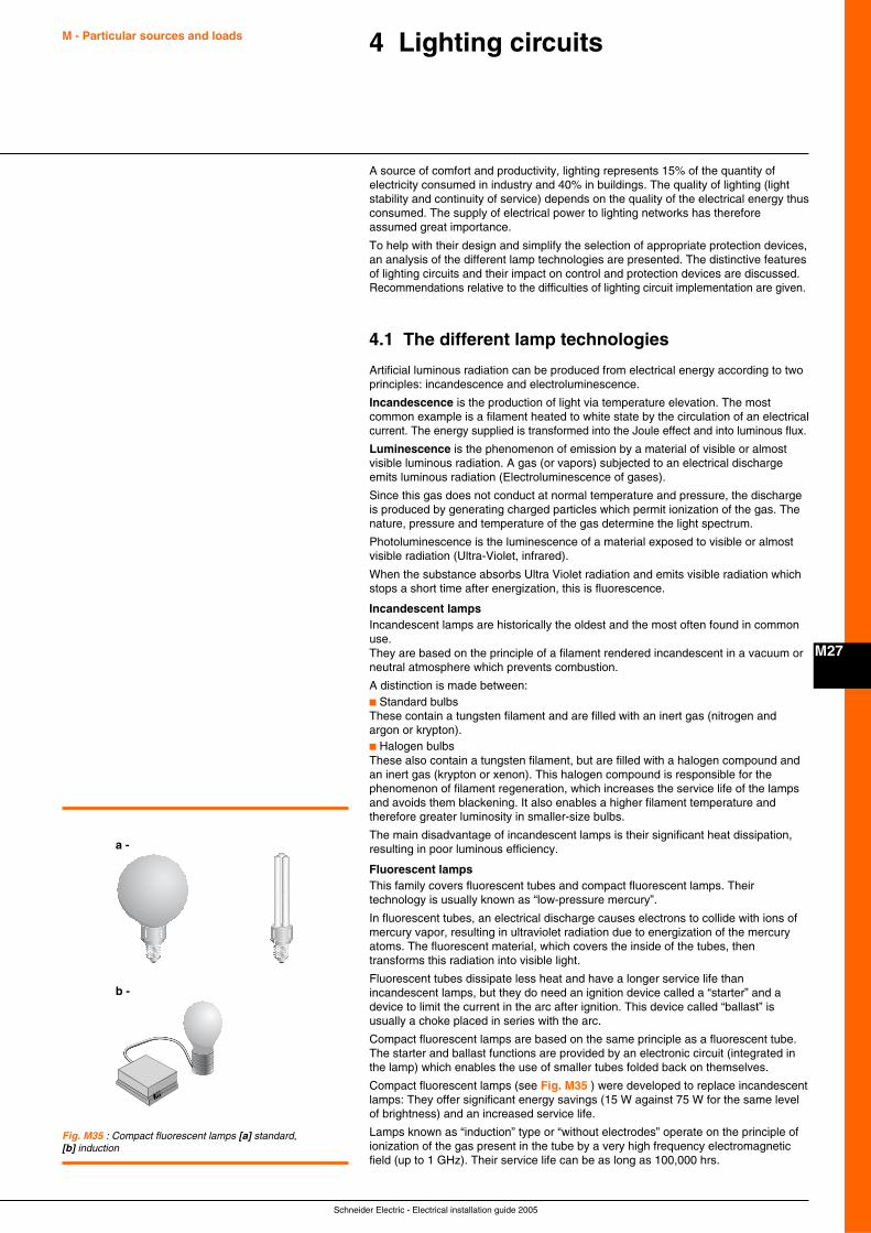
Schneider Electric - Electrical installation guide 2005
M - Particular sources and loads
M27
4 Lighting circuits
A source of comfort and productivity, lighting represents 15% of the quantity ofelectricity consumed in industry and 40% in buildings. The quality of lighting (lightstability and continuity of service) depends on the quality of the electrical energy thusconsumed. The supply of electrical power to lighting networks has thereforeassumed great importance.
To help with their design and simplify the selection of appropriate protection devices,an analysis of the different lamp technologies are presented. The distinctive featuresof lighting circuits and their impact on control and protection devices are discussed.Recommendations relative to the difficulties of lighting circuit implementation are given.
4.1 The different lamp technologies
Artificial luminous radiation can be produced from electrical energy according to twoprinciples: incandescence and electroluminescence.
Incandescence is the production of light via temperature elevation. The mostcommon example is a filament heated to white state by the circulation of an electricalcurrent. The energy supplied is transformed into the Joule effect and into luminous flux.
Luminescence is the phenomenon of emission by a material of visible or almostvisible luminous radiation. A gas (or vapors) subjected to an electrical dischargeemits luminous radiation (Electroluminescence of gases).
Since this gas does not conduct at normal temperature and pressure, the dischargeis produced by generating charged particles which permit ionization of the gas. Thenature, pressure and temperature of the gas determine the light spectrum.
Photoluminescence is the luminescence of a material exposed to visible or almostvisible radiation (Ultra-Violet, infrared).
When the substance absorbs Ultra Violet radiation and emits visible radiation whichstops a short time after energization, this is fluorescence.
Incandescent lampsIncandescent lamps are historically the oldest and the most often found in commonuse.They are based on the principle of a filament rendered incandescent in a vacuum orneutral atmosphere which prevents combustion.
A distinction is made between:c Standard bulbsThese contain a tungsten filament and are filled with an inert gas (nitrogen andargon or krypton).c Halogen bulbsThese also contain a tungsten filament, but are filled with a halogen compound andan inert gas (krypton or xenon). This halogen compound is responsible for thephenomenon of filament regeneration, which increases the service life of the lampsand avoids them blackening. It also enables a higher filament temperature andtherefore greater luminosity in smaller-size bulbs.
The main disadvantage of incandescent lamps is their significant heat dissipation,resulting in poor luminous efficiency.
Fluorescent lampsThis family covers fluorescent tubes and compact fluorescent lamps. Theirtechnology is usually known as “low-pressure mercury”.
In fluorescent tubes, an electrical discharge causes electrons to collide with ions ofmercury vapor, resulting in ultraviolet radiation due to energization of the mercuryatoms. The fluorescent material, which covers the inside of the tubes, thentransforms this radiation into visible light.
Fluorescent tubes dissipate less heat and have a longer service life thanincandescent lamps, but they do need an ignition device called a “starter” and adevice to limit the current in the arc after ignition. This device called “ballast” isusually a choke placed in series with the arc.
Compact fluorescent lamps are based on the same principle as a fluorescent tube.The starter and ballast functions are provided by an electronic circuit (integrated inthe lamp) which enables the use of smaller tubes folded back on themselves.
Compact fluorescent lamps (see Fig. M35 ) were developed to replace incandescentlamps: They offer significant energy savings (15 W against 75 W for the same levelof brightness) and an increased service life.
Lamps known as “induction” type or “without electrodes” operate on the principle ofionization of the gas present in the tube by a very high frequency electromagneticfield (up to 1 GHz). Their service life can be as long as 100,000 hrs.
Fig. M35 : Compact fluorescent lamps [a] standard,[b] induction
a -
b -
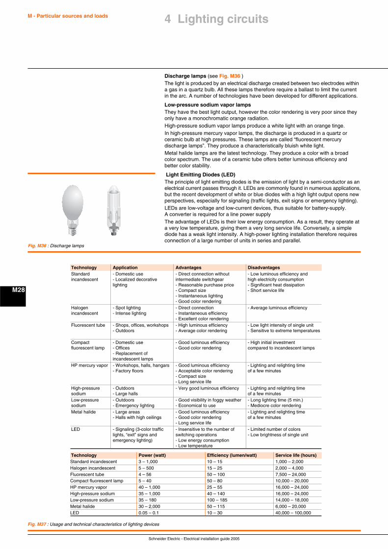
Schneider Electric - Electrical installation guide 2005
M - Particular sources and loads
M28
Discharge lamps (see Fig. M36 )The light is produced by an electrical discharge created between two electrodes withina gas in a quartz bulb. All these lamps therefore require a ballast to limit the currentin the arc. A number of technologies have been developed for different applications.
Low-pressure sodium vapor lampsThey have the best light output, however the color rendering is very poor since theyonly have a monochromatic orange radiation.High-pressure sodium vapor lamps produce a white light with an orange tinge.In high-pressure mercury vapor lamps, the discharge is produced in a quartz orceramic bulb at high pressures. These lamps are called “fluorescent mercurydischarge lamps”. They produce a characteristically bluish white light.Metal halide lamps are the latest technology. They produce a color with a broadcolor spectrum. The use of a ceramic tube offers better luminous efficiency andbetter color stability.
Light Emitting Diodes (LED)The principle of light emitting diodes is the emission of light by a semi-conductor as anelectrical current passes through it. LEDs are commonly found in numerous applications,but the recent development of white or blue diodes with a high light output opens newperspectives, especially for signaling (traffic lights, exit signs or emergency lighting).LEDs are low-voltage and low-current devices, thus suitable for battery-supply.A converter is required for a line power supplyThe advantage of LEDs is their low energy consumption. As a result, they operate ata very low temperature, giving them a very long service life. Conversely, a simplediode has a weak light intensity. A high-power lighting installation therefore requiresconnection of a large number of units in series and parallel.
Fig. M36 : Discharge lamps
Technology Application Advantages DisadvantagesStandard - Domestic use - Direct connection without - Low luminous efficiency andincandescent - Localized decorative intermediate switchgear high electricity consumption
lighting - Reasonable purchase price - Significant heat dissipation- Compact size - Short service life- Instantaneous lighting- Good color rendering
Halogen - Spot lighting - Direct connection - Average luminous efficiencyincandescent - Intense lighting - Instantaneous efficiency
- Excellent color renderingFluorescent tube - Shops, offices, workshops - High luminous efficiency - Low light intensity of single unit
- Outdoors - Average color rendering - Sensitive to extreme temperatures
Compact - Domestic use - Good luminous efficiency - High initial investmentfluorescent lamp - Offices - Good color rendering compared to incandescent lamps
- Replacement ofincandescent lamps
HP mercury vapor - Workshops, halls, hangars - Good luminous efficiency - Lighting and relighting time- Factory floors - Acceptable color rendering of a few minutes
- Compact size- Long service life
High-pressure - Outdoors - Very good luminous efficiency - Lighting and relighting timesodium - Large halls of a few minutesLow-pressure - Outdoors - Good visibility in foggy weather - Long lighting time (5 min.)sodium - Emergency lighting - Economical to use - Mediocre color renderingMetal halide - Large areas - Good luminous efficiency - Lighting and relighting time
- Halls with high ceilings - Good color rendering of a few minutes- Long service life
LED - Signaling (3-color traffic - Insensitive to the number of - Limited number of colorslights, “exit” signs and switching operations - Low brightness of single unitemergency lighting) - Low energy consumption
- Low temperature
Technology Power (watt) Efficiency (lumen/watt) Service life (hours)Standard incandescent 3 – 1,000 10 – 15 1,000 – 2,000Halogen incandescent 5 – 500 15 – 25 2,000 – 4,000Fluorescent tube 4 – 56 50 – 100 7,500 – 24,000Compact fluorescent lamp 5 – 40 50 – 80 10,000 – 20,000HP mercury vapor 40 – 1,000 25 – 55 16,000 – 24,000High-pressure sodium 35 – 1,000 40 – 140 16,000 – 24,000Low-pressure sodium 35 – 180 100 – 185 14,000 – 18,000Metal halide 30 – 2,000 50 – 115 6,000 – 20,000LED 0.05 – 0.1 10 – 30 40,000 – 100,000
Fig. M37 : Usage and technical characteristics of lighting devices
4 Lighting circuits
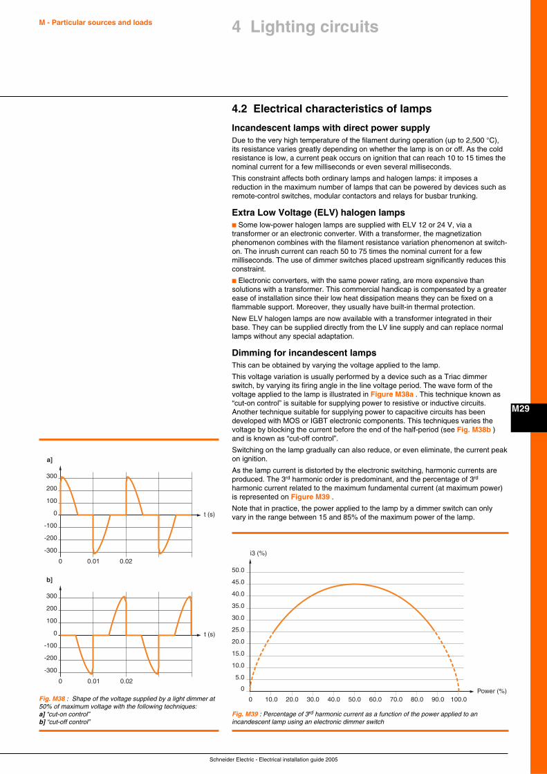
Schneider Electric - Electrical installation guide 2005
M - Particular sources and loads
M29
4 Lighting circuits
4.2 Electrical characteristics of lamps
Incandescent lamps with direct power supplyDue to the very high temperature of the filament during operation (up to 2,500 °C),its resistance varies greatly depending on whether the lamp is on or off. As the coldresistance is low, a current peak occurs on ignition that can reach 10 to 15 times thenominal current for a few milliseconds or even several milliseconds.
This constraint affects both ordinary lamps and halogen lamps: it imposes areduction in the maximum number of lamps that can be powered by devices such asremote-control switches, modular contactors and relays for busbar trunking.
Extra Low Voltage (ELV) halogen lampsc Some low-power halogen lamps are supplied with ELV 12 or 24 V, via atransformer or an electronic converter. With a transformer, the magnetizationphenomenon combines with the filament resistance variation phenomenon at switch-on. The inrush current can reach 50 to 75 times the nominal current for a fewmilliseconds. The use of dimmer switches placed upstream significantly reduces thisconstraint.
c Electronic converters, with the same power rating, are more expensive thansolutions with a transformer. This commercial handicap is compensated by a greaterease of installation since their low heat dissipation means they can be fixed on aflammable support. Moreover, they usually have built-in thermal protection.
New ELV halogen lamps are now available with a transformer integrated in theirbase. They can be supplied directly from the LV line supply and can replace normallamps without any special adaptation.
Dimming for incandescent lampsThis can be obtained by varying the voltage applied to the lamp.
This voltage variation is usually performed by a device such as a Triac dimmerswitch, by varying its firing angle in the line voltage period. The wave form of thevoltage applied to the lamp is illustrated in Figure M38a . This technique known as“cut-on control” is suitable for supplying power to resistive or inductive circuits.Another technique suitable for supplying power to capacitive circuits has beendeveloped with MOS or IGBT electronic components. This techniques varies thevoltage by blocking the current before the end of the half-period (see Fig. M38b )and is known as “cut-off control”.
Switching on the lamp gradually can also reduce, or even eliminate, the current peakon ignition.
As the lamp current is distorted by the electronic switching, harmonic currents areproduced. The 3rd harmonic order is predominant, and the percentage of 3rd
harmonic current related to the maximum fundamental current (at maximum power)is represented on Figure M39 .
Note that in practice, the power applied to the lamp by a dimmer switch can onlyvary in the range between 15 and 85% of the maximum power of the lamp.
300
200
100
0
0
t (s)
t (s)
0.01 0.02
-100
-200
-300
300
a]
b]
200
100
0
0 0.01 0.02
-100
-200
-300
Fig. M38 : Shape of the voltage supplied by a light dimmer at50% of maximum voltage with the following techniques:a] “cut-on control”b] “cut-off control”
0 10.0 20.0 30.0 40.0 50.0 60.0 70.0 80.0 90.0 100.0
50.0
45.0
40.0
35.0
30.0
25.0
20.0
15.0
10.0
5.0
0
i3 (%)
Power (%)
Fig. M39 : Percentage of 3rd harmonic current as a function of the power applied to anincandescent lamp using an electronic dimmer switch
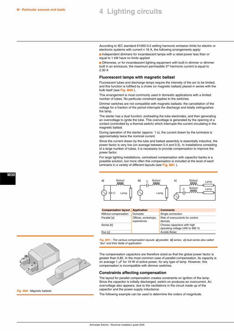
Schneider Electric - Electrical installation guide 2005
M - Particular sources and loads
M30
According to IEC standard 61000-3-2 setting harmonic emission limits for electric orelectronic systems with current i 16 A, the following arrangements apply:
c Independent dimmers for incandescent lamps with a rated power less than orequal to 1 kW have no limits applied
c Otherwise, or for incandescent lighting equipment with built-in dimmer or dimmerbuilt in an enclosure, the maximum permissible 3rd harmonic current is equal to2.30 A
Fluorescent lamps with magnetic ballastFluorescent tubes and discharge lamps require the intensity of the arc to be limited,and this function is fulfilled by a choke (or magnetic ballast) placed in series with thebulb itself (see Fig. M40 ).
This arrangement is most commonly used in domestic applications with a limitednumber of tubes. No particular constraint applies to the switches.
Dimmer switches are not compatible with magnetic ballasts: the cancellation of thevoltage for a fraction of the period interrupts the discharge and totally extinguishesthe lamp.
The starter has a dual function: preheating the tube electrodes, and then generatingan overvoltage to ignite the tube. This overvoltage is generated by the opening of acontact (controlled by a thermal switch) which interrupts the current circulating in themagnetic ballast.
During operation of the starter (approx. 1 s), the current drawn by the luminaire isapproximately twice the nominal current.
Since the current drawn by the tube and ballast assembly is essentially inductive, thepower factor is very low (on average between 0.4 and 0.5). In installations consistingof a large number of tubes, it is necessary to provide compensation to improve thepower factor.
For large lighting installations, centralized compensation with capacitor banks is apossible solution, but more often this compensation is included at the level of eachluminaire in a variety of different layouts (see Fig. M41 ).
Fig. M40 : Magnetic ballasts
a
a] b] c]C
Ballast Lamp
Ballast Lamp
Ca
Ballast
LampC a
Ballast
Lamp
Fig. M41 : The various compensation layouts: a] parallel; b] series; c] dual series also called“duo” and their fields of application
Compensation layout Application CommentsWithout compensation Domestic Single connectionParallel [a] Offices, workshops, Risk of overcurrents for control
superstores devicesSeries [b] Choose capacitors with high
operating voltage (450 to 480 V)Duo [c] Avoids flicker
The compensation capacitors are therefore sized so that the global power factor isgreater than 0.85. In the most common case of parallel compensation, its capacity ison average 1 µF for 10 W of active power, for any type of lamp. However, thiscompensation is incompatible with dimmer switches.
Constraints affecting compensationThe layout for parallel compensation creates constraints on ignition of the lamp.Since the capacitor is initially discharged, switch-on produces an overcurrent. Anovervoltage also appears, due to the oscillations in the circuit made up of thecapacitor and the power supply inductance.
The following example can be used to determine the orders of magnitude.
4 Lighting circuits
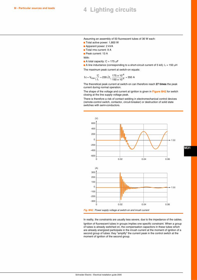
Schneider Electric - Electrical installation guide 2005
M - Particular sources and loads
M31
4 Lighting circuits
Assuming an assembly of 50 fluorescent tubes of 36 W each:c Total active power: 1,800 Wc Apparent power: 2 kVAc Total rms current: 9 Ac Peak current: 13 A
With:c A total capacity: C = 175 µFc A line inductance (corresponding to a short-circuit current of 5 kA): L = 150 µH
The maximum peak current at switch-on equals:
Ic VCL
= = =max
-6
-6 x 10
x 10 A230 2
175
150350
The theoretical peak current at switch-on can therefore reach 27 times the peakcurrent during normal operation.
The shape of the voltage and current at ignition is given in Figure M42 for switchclosing at the line supply voltage peak.
There is therefore a risk of contact welding in electromechanical control devices(remote-control switch, contactor, circuit-breaker) or destruction of solid stateswitches with semi-conductors.
Fig. M42 : Power supply voltage at switch-on and inrush current
600
400
200
0
-200
-400
-6000
(V)
t (s)
0.02 0.04 0.06
300
200
100
0
-100
-200
-3000
(A)
t (s)
0.02 0.04 0.06
In reality, the constraints are usually less severe, due to the impedance of the cables.
Ignition of fluorescent tubes in groups implies one specific constraint. When a groupof tubes is already switched on, the compensation capacitors in these tubes whichare already energized participate in the inrush current at the moment of ignition of asecond group of tubes: they “amplify” the current peak in the control switch at themoment of ignition of the second group.
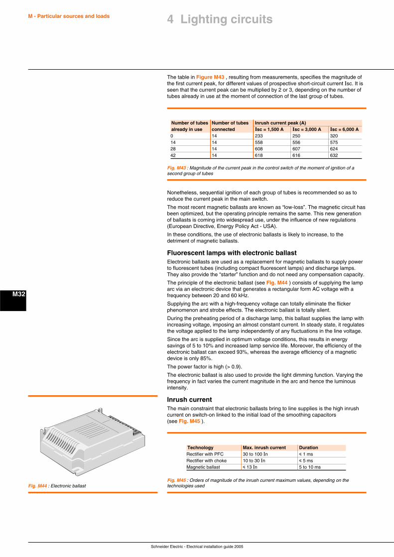
Schneider Electric - Electrical installation guide 2005
M - Particular sources and loads
M32
The table in Figure M43 , resulting from measurements, specifies the magnitude ofthe first current peak, for different values of prospective short-circuit current Isc. It isseen that the current peak can be multiplied by 2 or 3, depending on the number oftubes already in use at the moment of connection of the last group of tubes.
Fig. M43 : Magnitude of the current peak in the control switch of the moment of ignition of asecond group of tubes
Number of tubes Number of tubes Inrush current peak (A)already in use connected Isc = 1,500 A Isc = 3,000 A Isc = 6,000 A0 14 233 250 32014 14 558 556 57528 14 608 607 62442 14 618 616 632
Nonetheless, sequential ignition of each group of tubes is recommended so as toreduce the current peak in the main switch.
The most recent magnetic ballasts are known as “low-loss”. The magnetic circuit hasbeen optimized, but the operating principle remains the same. This new generationof ballasts is coming into widespread use, under the influence of new regulations(European Directive, Energy Policy Act - USA).
In these conditions, the use of electronic ballasts is likely to increase, to thedetriment of magnetic ballasts.
Fluorescent lamps with electronic ballastElectronic ballasts are used as a replacement for magnetic ballasts to supply powerto fluorescent tubes (including compact fluorescent lamps) and discharge lamps.They also provide the “starter” function and do not need any compensation capacity.
The principle of the electronic ballast (see Fig. M44 ) consists of supplying the lamparc via an electronic device that generates a rectangular form AC voltage with afrequency between 20 and 60 kHz.
Supplying the arc with a high-frequency voltage can totally eliminate the flickerphenomenon and strobe effects. The electronic ballast is totally silent.
During the preheating period of a discharge lamp, this ballast supplies the lamp withincreasing voltage, imposing an almost constant current. In steady state, it regulatesthe voltage applied to the lamp independently of any fluctuations in the line voltage.
Since the arc is supplied in optimum voltage conditions, this results in energysavings of 5 to 10% and increased lamp service life. Moreover, the efficiency of theelectronic ballast can exceed 93%, whereas the average efficiency of a magneticdevice is only 85%.
The power factor is high (> 0.9).
The electronic ballast is also used to provide the light dimming function. Varying thefrequency in fact varies the current magnitude in the arc and hence the luminousintensity.
Inrush currentThe main constraint that electronic ballasts bring to line supplies is the high inrushcurrent on switch-on linked to the initial load of the smoothing capacitors(see Fig. M45 ).
Fig. M44 : Electronic ballastFig. M45 : Orders of magnitude of the inrush current maximum values, depending on thetechnologies used
Technology Max. inrush current DurationRectifier with PFC 30 to 100 In i 1 msRectifier with choke 10 to 30 In i 5 msMagnetic ballast i 13 In 5 to 10 ms
4 Lighting circuits
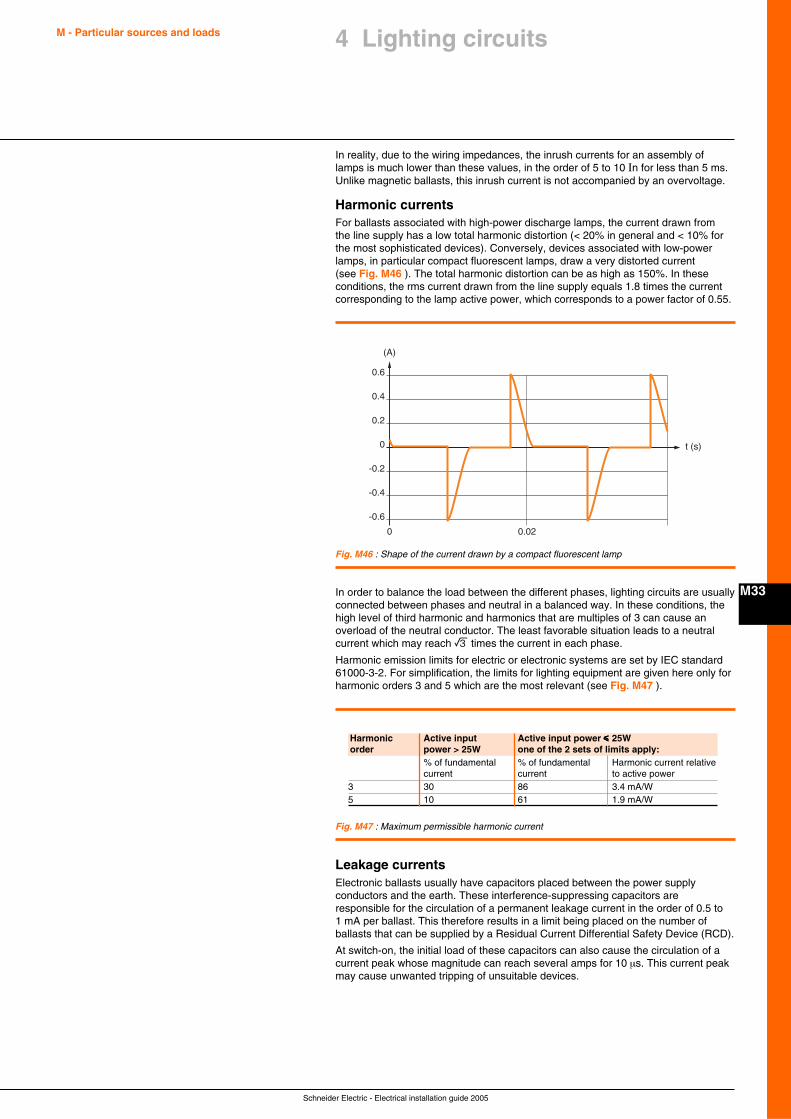
Schneider Electric - Electrical installation guide 2005
M - Particular sources and loads
M33
4 Lighting circuits
In reality, due to the wiring impedances, the inrush currents for an assembly oflamps is much lower than these values, in the order of 5 to 10 In for less than 5 ms.Unlike magnetic ballasts, this inrush current is not accompanied by an overvoltage.
Harmonic currentsFor ballasts associated with high-power discharge lamps, the current drawn fromthe line supply has a low total harmonic distortion (< 20% in general and < 10% forthe most sophisticated devices). Conversely, devices associated with low-powerlamps, in particular compact fluorescent lamps, draw a very distorted current(see Fig. M46 ). The total harmonic distortion can be as high as 150%. In theseconditions, the rms current drawn from the line supply equals 1.8 times the currentcorresponding to the lamp active power, which corresponds to a power factor of 0.55.
Fig. M46 : Shape of the current drawn by a compact fluorescent lamp
0.6
0.4
0.2
0
-0.2
-0.4
-0.6
0
(A)
t (s)
0.02
In order to balance the load between the different phases, lighting circuits are usuallyconnected between phases and neutral in a balanced way. In these conditions, thehigh level of third harmonic and harmonics that are multiples of 3 can cause anoverload of the neutral conductor. The least favorable situation leads to a neutralcurrent which may reach e times the current in each phase.
Harmonic emission limits for electric or electronic systems are set by IEC standard61000-3-2. For simplification, the limits for lighting equipment are given here only forharmonic orders 3 and 5 which are the most relevant (see Fig. M47 ).
Fig. M47 : Maximum permissible harmonic current
Harmonic Active input Active input power iiiii 25Worder power > 25W one of the 2 sets of limits apply:
% of fundamental % of fundamental Harmonic current relativecurrent current to active power
3 30 86 3.4 mA/W5 10 61 1.9 mA/W
Leakage currentsElectronic ballasts usually have capacitors placed between the power supplyconductors and the earth. These interference-suppressing capacitors areresponsible for the circulation of a permanent leakage current in the order of 0.5 to1 mA per ballast. This therefore results in a limit being placed on the number ofballasts that can be supplied by a Residual Current Differential Safety Device (RCD).
At switch-on, the initial load of these capacitors can also cause the circulation of acurrent peak whose magnitude can reach several amps for 10 µs. This current peakmay cause unwanted tripping of unsuitable devices.
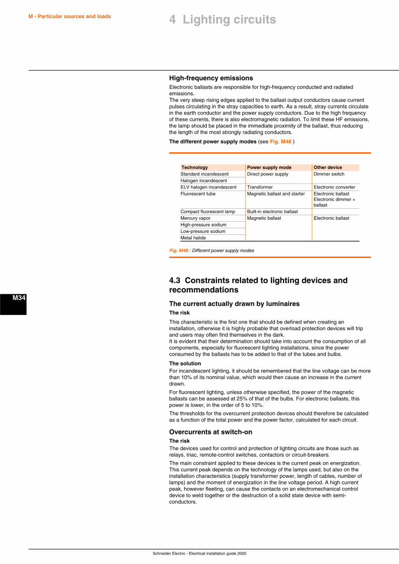
Schneider Electric - Electrical installation guide 2005
M - Particular sources and loads
M34
High-frequency emissionsElectronic ballasts are responsible for high-frequency conducted and radiatedemissions.The very steep rising edges applied to the ballast output conductors cause currentpulses circulating in the stray capacities to earth. As a result, stray currents circulatein the earth conductor and the power supply conductors. Due to the high frequencyof these currents, there is also electromagnetic radiation. To limit these HF emissions,the lamp should be placed in the immediate proximity of the ballast, thus reducingthe length of the most strongly radiating conductors.
The different power supply modes (see Fig. M48 )
Technology Power supply mode Other deviceStandard incandescent Direct power supply Dimmer switchHalogen incandescentELV halogen incandescent Transformer Electronic converterFluorescent tube Magnetic ballast and starter Electronic ballast
Electronic dimmer +ballast
Compact fluorescent lamp Built-in electronic ballastMercury vapor Magnetic ballast Electronic ballastHigh-pressure sodiumLow-pressure sodiumMetal halide
Fig. M48 : Different power supply modes
4.3 Constraints related to lighting devices andrecommendations
The current actually drawn by luminairesThe risk
This characteristic is the first one that should be defined when creating aninstallation, otherwise it is highly probable that overload protection devices will tripand users may often find themselves in the dark.It is evident that their determination should take into account the consumption of allcomponents, especially for fluorescent lighting installations, since the powerconsumed by the ballasts has to be added to that of the tubes and bulbs.
The solutionFor incandescent lighting, it should be remembered that the line voltage can be morethan 10% of its nominal value, which would then cause an increase in the currentdrawn.
For fluorescent lighting, unless otherwise specified, the power of the magneticballasts can be assessed at 25% of that of the bulbs. For electronic ballasts, thispower is lower, in the order of 5 to 10%.
The thresholds for the overcurrent protection devices should therefore be calculatedas a function of the total power and the power factor, calculated for each circuit.
Overcurrents at switch-onThe riskThe devices used for control and protection of lighting circuits are those such asrelays, triac, remote-control switches, contactors or circuit-breakers.
The main constraint applied to these devices is the current peak on energization.This current peak depends on the technology of the lamps used, but also on theinstallation characteristics (supply transformer power, length of cables, number oflamps) and the moment of energization in the line voltage period. A high currentpeak, however fleeting, can cause the contacts on an electromechanical controldevice to weld together or the destruction of a solid state device with semi-conductors.
4 Lighting circuits
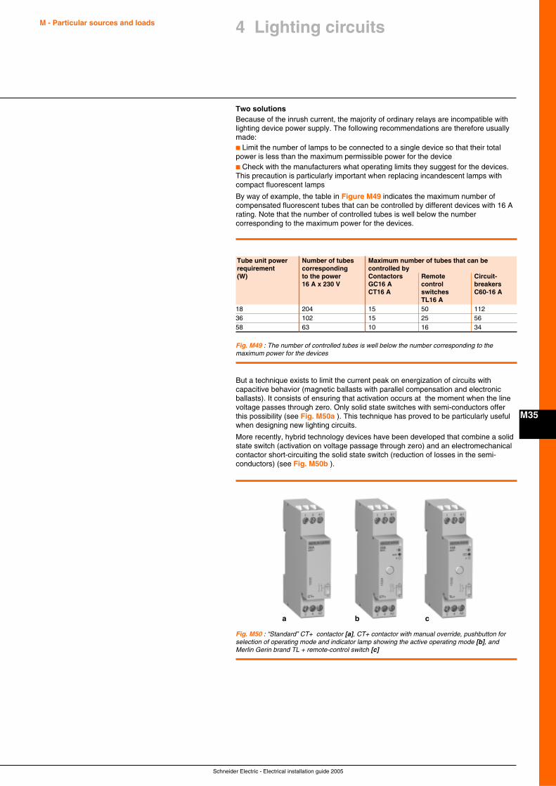
Schneider Electric - Electrical installation guide 2005
M - Particular sources and loads
M35
4 Lighting circuits
Two solutionsBecause of the inrush current, the majority of ordinary relays are incompatible withlighting device power supply. The following recommendations are therefore usuallymade:c Limit the number of lamps to be connected to a single device so that their totalpower is less than the maximum permissible power for the devicec Check with the manufacturers what operating limits they suggest for the devices.This precaution is particularly important when replacing incandescent lamps withcompact fluorescent lamps
By way of example, the table in Figure M49 indicates the maximum number ofcompensated fluorescent tubes that can be controlled by different devices with 16 Arating. Note that the number of controlled tubes is well below the numbercorresponding to the maximum power for the devices.
Fig. M49 : The number of controlled tubes is well below the number corresponding to themaximum power for the devices
Tube unit power Number of tubes Maximum number of tubes that can berequirement corresponding controlled by(W) to the power Contactors Remote Circuit-
16 A x 230 V GC16 A control breakersCT16 A switches C60-16 A
TL16 A18 204 15 50 11236 102 15 25 5658 63 10 16 34
But a technique exists to limit the current peak on energization of circuits withcapacitive behavior (magnetic ballasts with parallel compensation and electronicballasts). It consists of ensuring that activation occurs at the moment when the linevoltage passes through zero. Only solid state switches with semi-conductors offerthis possibility (see Fig. M50a ). This technique has proved to be particularly usefulwhen designing new lighting circuits.
More recently, hybrid technology devices have been developed that combine a solidstate switch (activation on voltage passage through zero) and an electromechanicalcontactor short-circuiting the solid state switch (reduction of losses in the semi-conductors) (see Fig. M50b ).
Fig. M50 : “Standard” CT+ contactor [a], CT+ contactor with manual override, pushbutton forselection of operating mode and indicator lamp showing the active operating mode [b], andMerlin Gerin brand TL + remote-control switch [c]
a b c
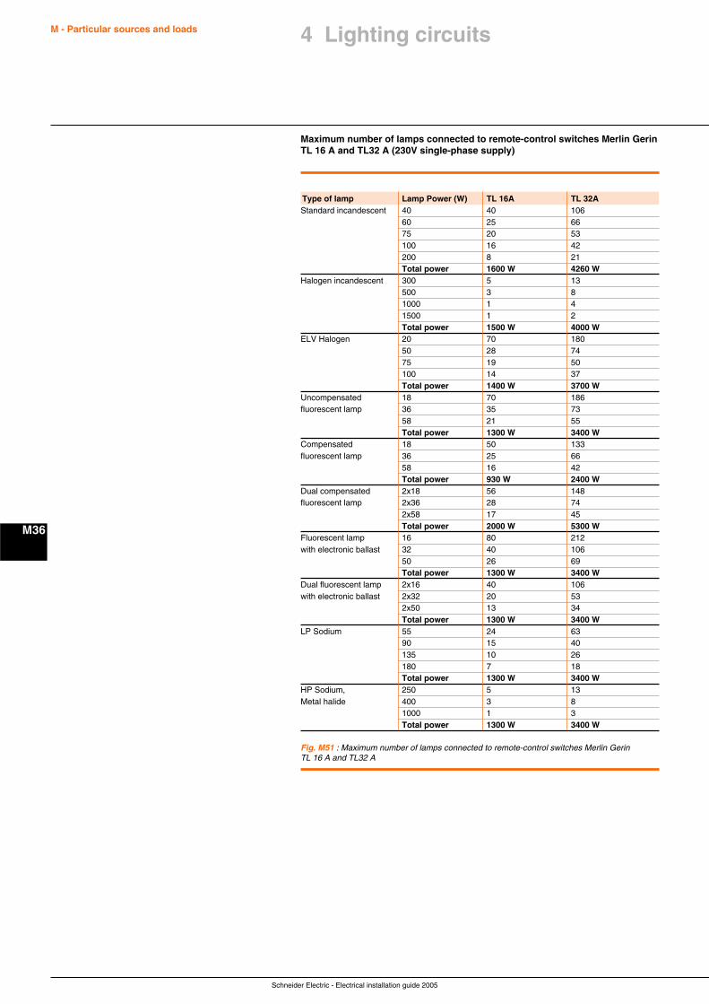
Schneider Electric - Electrical installation guide 2005
M - Particular sources and loads
M36
Maximum number of lamps connected to remote-control switches Merlin GerinTL 16 A and TL32 A (230V single-phase supply)
Type of lamp Lamp Power (W) TL 16A TL 32AStandard incandescent 40 40 106
60 25 6675 20 53100 16 42200 8 21Total power 1600 W 4260 W
Halogen incandescent 300 5 13500 3 81000 1 41500 1 2Total power 1500 W 4000 W
ELV Halogen 20 70 18050 28 7475 19 50100 14 37Total power 1400 W 3700 W
Uncompensated 18 70 186fluorescent lamp 36 35 73
58 21 55Total power 1300 W 3400 W
Compensated 18 50 133fluorescent lamp 36 25 66
58 16 42Total power 930 W 2400 W
Dual compensated 2x18 56 148fluorescent lamp 2x36 28 74
2x58 17 45Total power 2000 W 5300 W
Fluorescent lamp 16 80 212with electronic ballast 32 40 106
50 26 69Total power 1300 W 3400 W
Dual fluorescent lamp 2x16 40 106with electronic ballast 2x32 20 53
2x50 13 34Total power 1300 W 3400 W
LP Sodium 55 24 6390 15 40135 10 26180 7 18Total power 1300 W 3400 W
HP Sodium, 250 5 13Metal halide 400 3 8
1000 1 3Total power 1300 W 3400 W
Fig. M51 : Maximum number of lamps connected to remote-control switches Merlin GerinTL 16 A and TL32 A
4 Lighting circuits
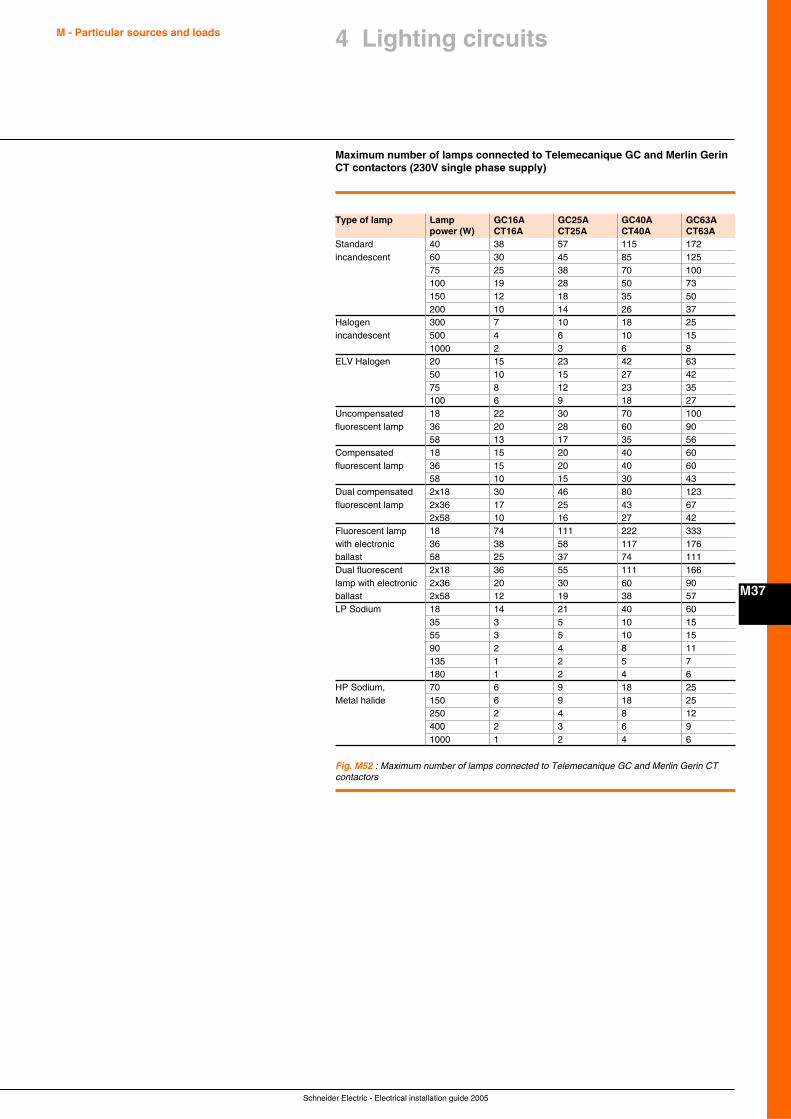
Schneider Electric - Electrical installation guide 2005
M - Particular sources and loads
M37
4 Lighting circuits
Maximum number of lamps connected to Telemecanique GC and Merlin GerinCT contactors (230V single phase supply)
Type of lamp Lamp GC16A GC25A GC40A GC63Apower (W) CT16A CT25A CT40A CT63A
Standard 40 38 57 115 172incandescent 60 30 45 85 125
75 25 38 70 100100 19 28 50 73150 12 18 35 50200 10 14 26 37
Halogen 300 7 10 18 25incandescent 500 4 6 10 15
1000 2 3 6 8ELV Halogen 20 15 23 42 63
50 10 15 27 4275 8 12 23 35100 6 9 18 27
Uncompensated 18 22 30 70 100fluorescent lamp 36 20 28 60 90
58 13 17 35 56Compensated 18 15 20 40 60fluorescent lamp 36 15 20 40 60
58 10 15 30 43Dual compensated 2x18 30 46 80 123fluorescent lamp 2x36 17 25 43 67
2x58 10 16 27 42Fluorescent lamp 18 74 111 222 333with electronic 36 38 58 117 176ballast 58 25 37 74 111Dual fluorescent 2x18 36 55 111 166lamp with electronic 2x36 20 30 60 90ballast 2x58 12 19 38 57LP Sodium 18 14 21 40 60
35 3 5 10 1555 3 5 10 1590 2 4 8 11135 1 2 5 7180 1 2 4 6
HP Sodium, 70 6 9 18 25Metal halide 150 6 9 18 25
250 2 4 8 12400 2 3 6 91000 1 2 4 6
Fig. M52 : Maximum number of lamps connected to Telemecanique GC and Merlin Gerin CTcontactors
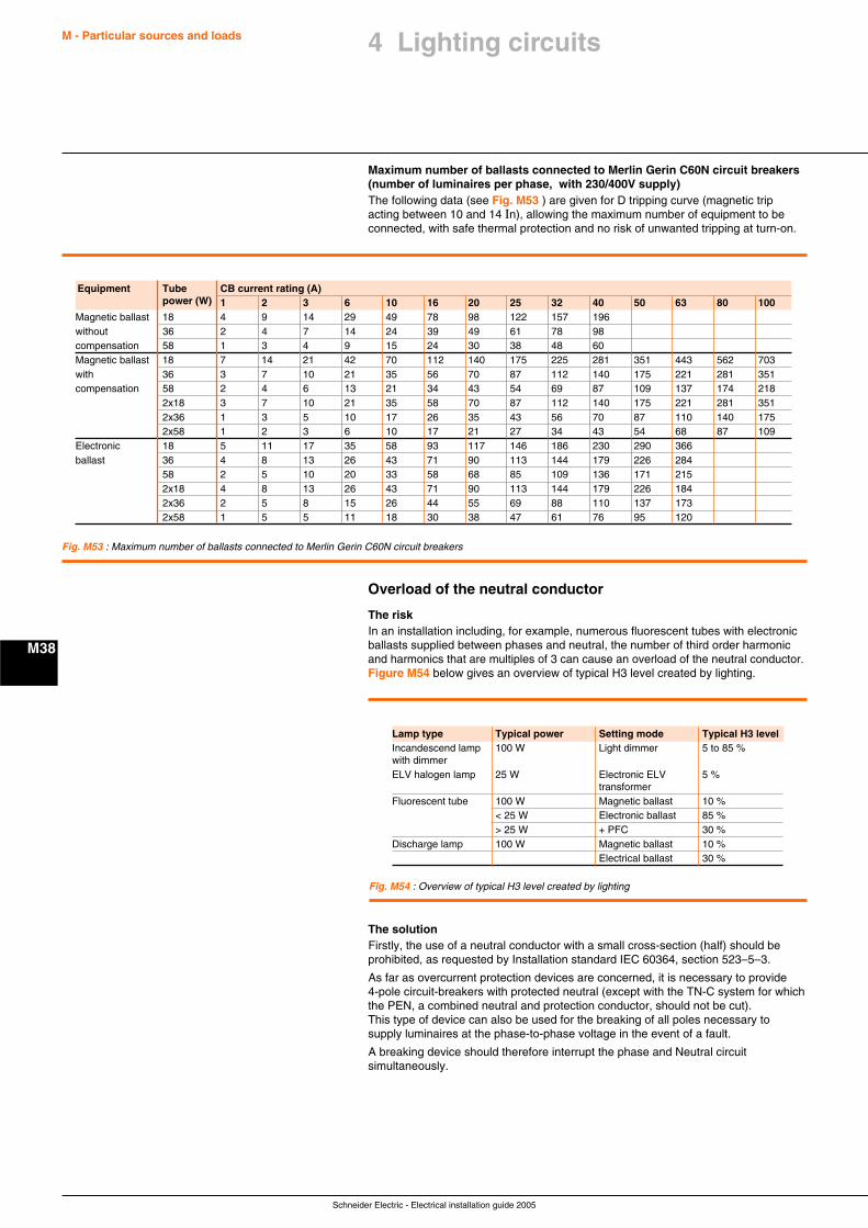
Schneider Electric - Electrical installation guide 2005
M - Particular sources and loads
M38
Maximum number of ballasts connected to Merlin Gerin C60N circuit breakers(number of luminaires per phase, with 230/400V supply)The following data (see Fig. M53 ) are given for D tripping curve (magnetic tripacting between 10 and 14 In), allowing the maximum number of equipment to beconnected, with safe thermal protection and no risk of unwanted tripping at turn-on.
Equipment Tube CB current rating (A)power (W) 1 2 3 6 10 16 20 25 32 40 50 63 80 100
Magnetic ballast 18 4 9 14 29 49 78 98 122 157 196without 36 2 4 7 14 24 39 49 61 78 98compensation 58 1 3 4 9 15 24 30 38 48 60Magnetic ballast 18 7 14 21 42 70 112 140 175 225 281 351 443 562 703with 36 3 7 10 21 35 56 70 87 112 140 175 221 281 351compensation 58 2 4 6 13 21 34 43 54 69 87 109 137 174 218
2x18 3 7 10 21 35 58 70 87 112 140 175 221 281 3512x36 1 3 5 10 17 26 35 43 56 70 87 110 140 1752x58 1 2 3 6 10 17 21 27 34 43 54 68 87 109
Electronic 18 5 11 17 35 58 93 117 146 186 230 290 366ballast 36 4 8 13 26 43 71 90 113 144 179 226 284
58 2 5 10 20 33 58 68 85 109 136 171 2152x18 4 8 13 26 43 71 90 113 144 179 226 1842x36 2 5 8 15 26 44 55 69 88 110 137 1732x58 1 5 5 11 18 30 38 47 61 76 95 120
Fig. M53 : Maximum number of ballasts connected to Merlin Gerin C60N circuit breakers
Overload of the neutral conductor
The riskIn an installation including, for example, numerous fluorescent tubes with electronicballasts supplied between phases and neutral, the number of third order harmonicand harmonics that are multiples of 3 can cause an overload of the neutral conductor.Figure M54 below gives an overview of typical H3 level created by lighting.
Lamp type Typical power Setting mode Typical H3 levelIncandescend lamp 100 W Light dimmer 5 to 85 %with dimmerELV halogen lamp 25 W Electronic ELV 5 %
transformerFluorescent tube 100 W Magnetic ballast 10 %
< 25 W Electronic ballast 85 %> 25 W + PFC 30 %
Discharge lamp 100 W Magnetic ballast 10 %Electrical ballast 30 %
Fig. M54 : Overview of typical H3 level created by lighting
The solutionFirstly, the use of a neutral conductor with a small cross-section (half) should beprohibited, as requested by Installation standard IEC 60364, section 523–5–3.
As far as overcurrent protection devices are concerned, it is necessary to provide4-pole circuit-breakers with protected neutral (except with the TN-C system for whichthe PEN, a combined neutral and protection conductor, should not be cut).This type of device can also be used for the breaking of all poles necessary tosupply luminaires at the phase-to-phase voltage in the event of a fault.
A breaking device should therefore interrupt the phase and Neutral circuitsimultaneously.
4 Lighting circuits
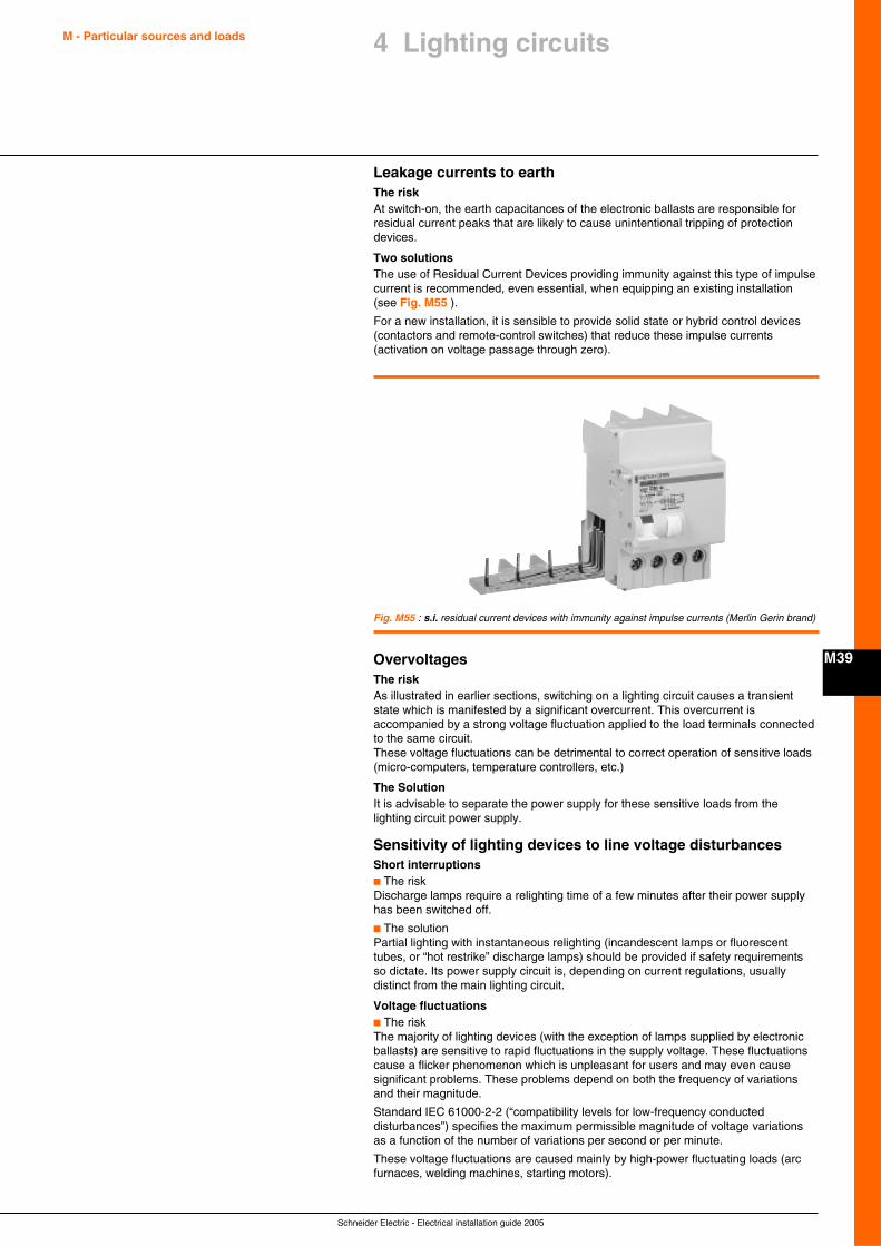
Schneider Electric - Electrical installation guide 2005
M - Particular sources and loads
M39
4 Lighting circuits
Leakage currents to earthThe riskAt switch-on, the earth capacitances of the electronic ballasts are responsible forresidual current peaks that are likely to cause unintentional tripping of protectiondevices.
Two solutionsThe use of Residual Current Devices providing immunity against this type of impulsecurrent is recommended, even essential, when equipping an existing installation(see Fig. M55 ).
For a new installation, it is sensible to provide solid state or hybrid control devices(contactors and remote-control switches) that reduce these impulse currents(activation on voltage passage through zero).
Fig. M55 : s.i. residual current devices with immunity against impulse currents (Merlin Gerin brand)
OvervoltagesThe riskAs illustrated in earlier sections, switching on a lighting circuit causes a transientstate which is manifested by a significant overcurrent. This overcurrent isaccompanied by a strong voltage fluctuation applied to the load terminals connectedto the same circuit.These voltage fluctuations can be detrimental to correct operation of sensitive loads(micro-computers, temperature controllers, etc.)
The SolutionIt is advisable to separate the power supply for these sensitive loads from thelighting circuit power supply.
Sensitivity of lighting devices to line voltage disturbancesShort interruptionsc The riskDischarge lamps require a relighting time of a few minutes after their power supplyhas been switched off.
c The solutionPartial lighting with instantaneous relighting (incandescent lamps or fluorescenttubes, or “hot restrike” discharge lamps) should be provided if safety requirementsso dictate. Its power supply circuit is, depending on current regulations, usuallydistinct from the main lighting circuit.
Voltage fluctuationsc The riskThe majority of lighting devices (with the exception of lamps supplied by electronicballasts) are sensitive to rapid fluctuations in the supply voltage. These fluctuationscause a flicker phenomenon which is unpleasant for users and may even causesignificant problems. These problems depend on both the frequency of variationsand their magnitude.
Standard IEC 61000-2-2 (“compatibility levels for low-frequency conducteddisturbances”) specifies the maximum permissible magnitude of voltage variationsas a function of the number of variations per second or per minute.
These voltage fluctuations are caused mainly by high-power fluctuating loads (arcfurnaces, welding machines, starting motors).
Schneider Electric - Electrical installation guide 2005
M - Particular sources and loads
M40
c The solutionSpecial methods can be used to reduce voltage fluctuations. Nonetheless, it isadvisable, wherever possible, to supply lighting circuits via a separate line supply.The use of electronic ballasts is recommended for demanding applications(hospitals, clean rooms, inspection rooms, computer rooms, etc).
Developments in control and protection equipmentThe use of light dimmers is more and more common. The constraints on ignition aretherefore reduced and derating of control and protection equipment is less important.New protection devices adapted to the constraints on lighting circuits are beingintroduced, for example Merlin Gerin brand circuit-breakers and modular residualcurrent circuit-breakers with special immunity, such as ID switches and s.i. typeVigi circuit-breakers. As control and protection equipment evolves, some now offerremote control, 24-hour management, lighting control, reduced consumption, etc.
4.4 Lighting of public areas
Normal lightingRegulations governing the minimum requirements for buildings receiving the publicin most European countries are as follows:
c Installations which illuminates areas accessible to the public must be controlledand protected independently from installations providing illumination to other areas
c Loss of supply on a final lighting circuit (i.e. fuse blown or CB tripped) must notresult in total loss of illumination in an area which is capable of accommodating morethan 50 persons
c Protection by Residual Current Devices (RCD) must be divided amongst severaldevices (i.e. more than on device must be used)
Emergency lightingThese schemes include illuminated emergency exit signs and direction indications,as well as general lighting.
Emergency exit indicationIn areas accommodating more than 50 persons, luminous directional indications tothe nearest emergency exits must be provided.
General emergency lightingGeneral lighting is obligatory when an area can accommodate 100 persons or more(50 persons or more in areas below ground level).
A fault on a lighting distribution circuit must not affect any other circuit:c The discrimination of overcurrent protection relays and of RCD must be absolute,so that only the faulty circuit must be cut offc The installation must be an IT scheme, or must be entirely class II, i.e. doublyisolated
Supply sources for emergency lightingSupply sources for emergency-lighting systems must be capable of maintaining thesupply to all lamps in the most unfavorable circumstances likely to occur, and for aperiod judged necessary to ensure the total evacuation of the premises concerned,with (in any case) a minimum of one hour.
Compatibility between emergency lighting and other parts ofthe installationEmergency-lighting sources must supply exclusively the circuits installed only foroperations in emergency situations.
Standby lighting systems operate to maintain illumination on failure of normal lightingcircuits (generally in non-emergency circumstances). However, failure of standbylighting must automatically bring the emergency lighting system into operation.
Central sources for emergency supplies may also be used to provide stand-bysupplies, provided that the following conditions are simultaneously fulfilled:c Where there are several sources, the failure of one source must leave sufficientcapacity in service to maintain supply to all safety systems, with automatic loadshedding of non-essential loads (if necessary)c The failure of one source, or one equipment concerned with safety, must leave allother sources and safety equipment unaffectedc Any safety equipment must be arranged to receive supply from any source
4 Lighting circuits
Schneider Electric - Electrical installation guide 2005
M - Particular sources and loads
M41
4 Lighting circuits
Classification of emergency-lighting schemesMany countries have statutory regulations concerning safety in buildings and areasintended for public gatherings.
Classification of such locations leads to the determination of suitable types ofsolutions, authorized for use in emergency-lighting schemes in the different areas.The following four classifications are typical:
Type AThe lamps are supplied permanently and totally in the presence of the public by asingle central source (battery or storage cell, or a heat-engine driven generator).These circuits must be independent of any other circuits (1).
Type BThe lamps are permanently supplied during the presence of the public, either:c By battery to which the lamps are permanently connected, and which is onpermanent trickle charge from a normal lighting source, orc By a heat-engine driven generator, the characteristics of which also assuresupplies to essential loads within one second (since the set is already running andsupplying the emergency lighting) in the event of failure of the normal supply, orc By autonomous units which are normally supplied and permanently alight from thenormal lighting supply, and which remain alight (at least for one hour), on the loss ofnormal supply, by virtue of a self contained battery. The battery is trickle-charged innormal circumstances. These units have fluorescent lamps for general emergencylighting, and fluorescent or incandescent lamps or incandescent lamps for exit anddirection-indicating signs. The circuits for all emergency lamps must be independentof any other circuits (1)
Type CThe lamps may or may not be supplied in normal conditions and if supplied, may befed from the normal lighting system, or from the emergency-lighting supply.c The emergency-lighting batteries must be maintained on charge from the normalsource by automatically regulated systems, that ensure a minimum of capacity equalto the full emergency-lighting load of one hourc The heat-engine driven generator sets must be capable of automatically picking-upthe full emergency lighting load from stand-by (stationary) condition, in less than15 seconds, following the failure of normal supply. The engine start-up power isprovided by a battery which is capable of six starting attempts, or by a system ofcompressed air. Minimum reserves of energy in the two systems of start-up must bemaintained automatically.c Failures in the central emergency supply source must be detected at a sufficientnumber of points and adequately signaled to supervisory/maintenance personnelc Autonomous units may be of the permanently-lit type or non-permanently-lit type.The circuits of all emergency lamps must be independent of any other circuits (2).
Type DThis type of emergency lighting comprises hand-carried battery-powered (primary orsecondary cells) at the disposal of service personnel or the public.
(1) Circuits for types A and B, in the case of a centralemergency power source, must also be fire-resistant. Conduitboxes junction sleeves, and so on must satisfy nationalstandards heat tests, or the circuits must be installed inprotective cable chases, trunking, etc. capable of assuringsatisfactory performance for at lest one hour in the event of fire(2) Cable circuits of type C are nor required to comply with theconditions of (1)
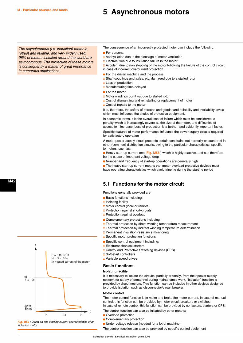
Schneider Electric - Electrical installation guide 2005
M - Particular sources and loads
M42
5 Asynchronous motors
The consequence of an incorrectly protected motor can include the following:
c For persons:v Asphyxiation due to the blockage of motor ventilationv Electrocution due to insulation failure in the motorv Accident due to non stopping of the motor following the failure of the control circuitin case of incorrect overcurrent protection
c For the driven machine and the processv Shaft couplings and axles, etc, damaged due to a stalled rotorv Loss of productionv Manufacturing time delayed
c For the motorv Motor windings burnt out due to stalled rotorv Cost of dismantling and reinstalling or replacement of motorv Cost of repairs to the motor
It is, therefore, the safety of persons and goods, and reliability and availability levelswhich must influence the choice of protective equipment.
In economic terms, it is the overall cost of failure which must be considered; apenalty which is increasingly severe as the size of the motor, and difficulties ofaccess to it increase. Loss of production is a further, and evidently important factor.
Specific features of motor performance influence the power supply circuits requiredfor satisfactory operation
A motor power-supply circuit presents certain constrains not normally encountered inother (common) distribution circuits, owing to the particular characteristics, specificto motors, such as:c Heavy start-up current (see Fig. M56 ) which is highly reactive, and can thereforebe the cause of important voltage dropc Number and frequency of start-up operations are generally highc The heavy start-up current means that motor overload protective devices musthave operating characteristics which avoid tripping during the starting period
5.1 Functions for the motor circuit
Functions generally provided are:
c Basic functions including:v Isolating facilityv Motor control (local or remote)v Protection against short-circuitsv Protection against overload
c Complementary protections including:v Thermal protection by direct winding temperature measurementv Thermal protection by indirect winding temperature determinationv Permanent insulation-resistance monitoringv Specific motor protection functions
c Specific control equipment including:v Electromechanical startersv Control and Protective Switching devices (CPS)v Soft-start controllersv Variable speed drives
Basic functionsIsolating facilityIt is necessary to isolate the circuits, partially or totally, from their power supplynetwork for satety of personnel during maintenance work. “Isolation” function isprovided by disconnectors. This function can be included in other devices designedto provide isolation such as disconnector/circuit breaker.
Motor controlThe motor control function is to make and brake the motor current. In case of manualcontrol, this function can be provided by motor-circuit breakers or switches.In case of remote control, this function can be provided by contactors, starters or CPS.
The control function can also be initiated by other means:c Overload protectionc Complementary protectionc Under voltage release (needed for a lot of machine)
The control function can also be provided by specific control equipment
The asynchronous (i.e. induction) motor isrobust and reliable, and very widely used.95% of motors installed around the world areasynchronous. The protection of these motorsis consequently a matter of great importancein numerous applications.
Fig. M56 : Direct on-line starting current characteristics of aninduction motor
I" = 8 to 12 InId = 5 to 8 InIn = rated current of the motor
In Id I"I
20 to30 ms
td1 to 10s
t

Schneider Electric - Electrical installation guide 2005
M - Particular sources and loads
M43
5 Asynchronous motors
Protection against short-circuitsc Phase-to-phase short circuitThis type of fault inside the machine is very rare. It is generally due to mechanicalincident of the power supply cable of the motor.
c Phase-to-earth short circuitThe deterioration of winding insulation is the main cause. The resulting fault currentdepends on the system of earthing. For the TN system, the resulting fault current isvery great and in most cases the motor will be deteriorated. For the other systems ofearthing, protection of the motor can be achieved by earth fault protection.
For short circuit protection, it is recommended to pay special attention to avoidunexpected tripping during the starting period of the motor. The inrush current of astandard motor is from about 6 to 8 times its rated current but during a fault thecurrent can be only 15 times the rated current. So, the starting current must not beseen as a fault by the protection. In addition, a fault occuring in a motor circuit mustnot disturb any upstream circuit. As a consequence, discrimination and filiation/selectivity of magnetic protections must be respected with all parts of the installation.
Protection against overloadMechanical overloads due to the driven machine are the main origins of the overloadfor a motor application. They cause overload current and motor overheating. The lifeof the motor can be reduced and sometimes, the motor can be deteriorated. So, it isnecessary to detect motor overload. This protection can be provided by:c Specific thermal overload relayc Specific thermal-magnetic circuit breaker commonly referred to as “motor circuitbreaker”c Complementary protection (see below) like thermal sensor or electronicmultifunction relayc Electronic soft start controllers or variable speed drives (see below)
Complementary protectionsc Thermal protection by direct winding temperature measurementProvided by thermal sensors incorporated inside the windings of the motor andassociated relays.
c Thermal protection by indirect winding temperature determinationProvided by multifunction relays through current measurement and taking intoaccount the characteristics of the motors.
c Permanent insulation-resistance monitoring relays or residual current differentialrelaysThey provide detection and protection against earth leakage current and short circuitto earth, allowing maintenance operation before destruction of the motor.
c Specific motor protection functionsSuch as protection against too long starting period or stalled rotor, protection againstunbalanced, loss or permutation of phase, earth fault protection, no load protection,rotor blocked(during start or after)…; pre alarm overheating indication,communication, can also be provided by multifunction relays.
Specific control equipmentc Electromechanical starters (star-delta, auto-transformer, rheostatic rotorstarters,…)They are generally used for application with no load during the starting period(pump, fan, small centrifuge, machine-tool, etc.)v AdvantagesGood ratio torque/current; great reduction of inrush current.v DisadvantagesLow torque during the starting period; no facility of adjustment; power cut off duringthe transition and transient phenomenon; 6 motor connection cables needed.
c Control and Protective Switching devices (CPS)They provide all the basic functions listed before within a single unit and also somecomplementary functions and the possibility of communication. These devices alsoprovide continuity of service in case of short circuit.
c Soft-start controllersUsed for applications with pump, fan, compressor, conveyor.v AdvantagesLimitation of peak of current, voltage drop, mechanical strenghts during the motorstart, built-in thermal protection, small size device. possibility of communicationv DisadvantagesLow torque during the starting period; thermal dissipation.
Schneider Electric - Electrical installation guide 2005
M - Particular sources and loads
M44
c Variable speed drivesThey are used for applications with pump, fan, compressor, conveyor, machine withgreat load torque, machine with great inertia.v AdvantagesContinuous speed variation (adjustment typically from 2 to 130% of nominal speed),overspeed is possible; accurate control of acceleration and deceleration; high torqueduring the starting and the stop periods; low inrush current, built-in thermal protection,possibility of communication.v DisadvantagesThermal dissipation, volume, cost.
5.2 Standards
The motor control and protection can be achieved in different way:c By using an association of a SCPD (Short-Circuit-Protective-Device) andelectromechanical devices such asv An electromechanical starters fulfilling the standard IEC 60947-4-1v A semiconductor starter fulfilling the standard IEC 60947-4-2v A variable speed drives fulfilling the standard series IEC 61800c By using a CPS, single device covering all the basic functions, and fulfilling thestandard IEC 60947-6-2
In this document, only the motor circuits including association of electromechanicaldevices such as, starters and protection against short-circuit, are considered. Thedevices meeting the standard 60947-6-2, the semiconductor starters and the variablespeed drives will be considered only for specific points.
A motor circuit will meet the rules of the IEC 60947-4-1 and mainly:c The co-ordination between the devices of the motor circuitc The tripping class of the thermal relaysc The category of utilization of the contactorsc The insulation co-ordination
Note: The first and last points are satisfied inherently by the devices meeting theIEC 60947-6-2 because they provide a continuity of service.
Standardization of the association circuit breaker + contactor+ thermal relayUtilization categorie of the contactorsThe standard IEC 60947-4-1 gives utilization categories which considerably facilitatethe choice of a suitable contactor for a given service duty. The utilization categoriesadvise on:c A range of functions for which the contactor must be adaptedc The required current breaking and making capabilitiesc Standard values for on load durability tests, according to the utilization category.
Figure M57 gives some typical examples of the utilization categories covered.
Fig. M57 : Utilization categories for contactors
Utilization category Application characteristicsAC-1 Non-inductive (or slightly inductive) loads:
cos ϕ u 0.95 (heating, distribution)AC-2 Starting and switching off of slip-ring motorsAC-3 Cage motors: Starting, and switching off motors
during runningAC-4 Cage motors: Starting, plugging, inching
Note: These utilization categories are adapted to the devices meeting the othersstandards. For example AC-3 becomes AC-53 for the semiconductor starters(IEC 60947-4-2) and becomes AC-43 for CPS’s (IEC 60947-6-2).
5 Asynchronous motors

Schneider Electric - Electrical installation guide 2005
M - Particular sources and loads
M45
5 Asynchronous motors
The types of co-ordinationFor each association of devices, a type of co-ordination is given, according to thestate of the constituant parts following a circuit breaker trip out on fault, or theopening of a contactor on overload.
The standard IEC 947-4-1 defines two types of co-ordination, type 1 and type 2,which set maximum allowable limits of deterioration of switchgear, in case of short-circuit.
Whatever the type of co-ordination, it is required that the contactor or the starter mustnever present a danger for the personnel and for the installation. The specificities ofeach type are:c Type 1Deterioration of the starter is acceptable after a short-circuit and the operation of thestarter may be recovered after reparing or replacing some parts.c Type 2Burning and the risk of welding of the contacts of the contactor are the only risksallowed.
Which type to choose?The type of co-ordination to adop depends on the parameters of exploitation and mustbe chosen to satisfy (optimally) the needs of the user and the cost of installation.c Type 1v Qualified maintenance servicev Volume and cost of switchgear reducedv May not be suitable for further service without repair or replacement of parts after ashort-circuitc Type 2v Only light maintenance measures for further use after a short-circuit
5.3 Applications
The control and protection of a motor can consist of one, two, three or four differentdevices which provide one or several functions.
In the case of the combination of several devices, co-ordination between themis essential in order to provide optimized protection of the motor application.To protect a motor circuit, many parameters must be taken into account, theydepend on:c The application (type of driven machine, safety of operation, number of operations,etc.)c The continuity performance requested by the applicationc The standards to be enforced to provide security and safety.
The electrical functions to be provided are quite different:c Start, normal operation and stop without unexpected tripping while maintainingcontrol requirements, number of operations, durability and safety requirements(emergency stops), as well as circuit and motor protection, disconnection (isolation)for safety of personnel during maintenance work.
Basic protection schemes: circuit breaker + contactor+ thermal relayAvantagesThe combination of devices facilitates installation work, as well as operation andmaintenance, by:c The reduction of the maintenance work load: the circuit breaker avoids the need toreplace blown fuses and the necessity of maintaining a stock (of different sizes andtypes)c Better continuity performance: the installation can be re-energizes immediatelyfollowing the elimination of a fault and after checking of the starterc Additional complementary devices sometimes required on a motor circuit areeasily accomodatedc Tripping of all three phases is assured (thereby avoiding the possibility of “singlephasing”)c Full load current switching possibility (by circuit breaker) in the event of contactorfailure, e.g. contact weldingc Interlockingc Diverse remote indications
Among the many possible methods ofprotecting a motor, the association of acircuit breaker + contactor + thermal relay (1)
provides many advantages
(1) The combination of a contactor with a thermal relay iscommonly referred to as a “discontactor”
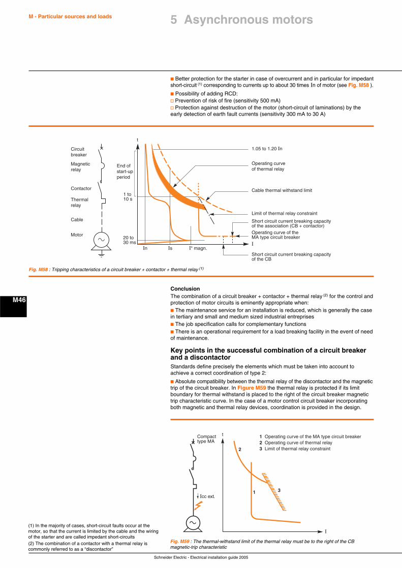
Schneider Electric - Electrical installation guide 2005
M - Particular sources and loads
M46
c Better protection for the starter in case of overcurrent and in particular for impedantshort-circuit (1) corresponding to currents up to about 30 times In of motor (see Fig. M58 ).
c Possibility of adding RCD:v Prevention of risk of fire (sensitivity 500 mA)v Protection against destruction of the motor (short-circuit of laminations) by theearly detection of earth fault currents (sensitivity 300 mA to 30 A)
(1) In the majority of cases, short-circuit faults occur at themotor, so that the current is limited by the cable and the wiringof the starter and are called impedant short-circuits(2) The combination of a contactor with a thermal relay iscommonly referred to as a “discontactor”
Fig. M58 : Tripping characteristics of a circuit breaker + contactor + thermal relay (1)
t
In Is
Limit of thermal relay constraint
Operating curve of the MA type circuit breakerI
Circuitbreaker
Magneticrelay
Contactor
Thermalrelay
Cable
Motor
End ofstart-upperiod
1 to10 s
20 to 30 ms
I" magn.
Cable thermal withstand limit
Operating curveof thermal relay
1.05 to 1.20 In
Short circuit current breaking capacityof the association (CB + contactor)
Short circuit current breaking capacity of the CB
ConclusionThe combination of a circuit breaker + contactor + thermal relay (2) for the control andprotection of motor circuits is eminently appropriate when:c The maintenance service for an installation is reduced, which is generally the casein tertiary and small and medium sized industrial entreprisesc The job specification calls for complementary functionsc There is an operational requirement for a load breaking facility in the event of needof maintenance.
Key points in the successful combination of a circuit breakerand a discontactorStandards define precisely the elements which must be taken into account toachieve a correct coordination of type 2:
c Absolute compatibility between the thermal relay of the discontactor and the magnetictrip of the circuit breaker. In Figure M59 the thermal relay is protected if its limitboundary for thermal withstand is placed to the right of the circuit breaker magnetictrip characteristic curve. In the case of a motor control circuit breaker incorporatingboth magnetic and thermal relay devices, coordination is provided in the design.
Fig. M59 : The thermal-withstand limit of the thermal relay must be to the right of the CBmagnetic-trip characteristic
1 Operating curve of the MA type circuit breaker2 Operating curve of thermal relay3 Limit of thermal relay constraint
Compacttype MA
Icc ext.31
2
t
I
5 Asynchronous motors
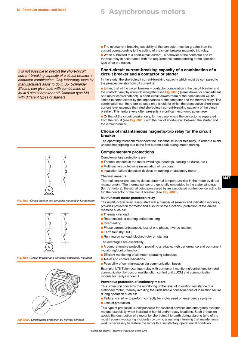
Schneider Electric - Electrical installation guide 2005
M - Particular sources and loads
M47
5 Asynchronous motors
c The overcurrent breaking capability of the contactor must be greater than thecurrent corresponding to the setting of the circuit breaker magnetic trip relay.c When submitted to a short-circuit current, a behavior of the contactor and itsthermal relay in accordance with the requirements corresponding to the specifiedtype of co-ordination.
Short-circuit current-breaking capacity of a combination of acircuit breaker and a contactor or starterIn the study, the short-circuit current-breaking capacity which must be compared tothe prospective short-circuit current is:
c Either, that of the circuit breaker + contactor combination if the circuit breaker andthe contactor are physically close together (see Fig. M60 ) (same drawer or compartmentof a motor control cabinet). A short-circuit downstream of the combination will belimited to some extent by the impedances of the contactor and the thermal relay. Thecombination can therefore be used on a circuit for which the prospective short-circuitcurrent level exceeds the rated short-circuit current-breaking capacity of the circuitbreaker. This feature very often presents a significant economic advantage
c Or that of the circuit breaker only, for the case where the contactor is separatedfrom the circuit (see Fig. M61 ) with the risk of short-circuit between the starter andthe circuit breaker.
Choice of instantaneous magnetic-trip relay for the circuitbreakerThe operating threshold must never be less than 12 In for this relay, in order to avoidunexpected tripping due to the first current peak during motor starting.
Complementary protectionsComplementary protections are:c Thermal sensors in the motor (windings, bearings, cooling-air ducts, etc.)c Multifunction protections (association of functions)c Insulation-failure detection devices on running or stationary motor
Thermal sensorsThermal sensor are used to detect abnormal temperature rise in the motor by directmeasurement. The thermal sensor are generally embedded in the stator windings(for LV motors), the signal being processed by an associated control device acting totrip the contactor or the circuit breaker (see Fig. M62 ).
Mutifunction motor protection relayThe multifunction relay, associated with a number of sensors and indication modules,provides protection for motor and also for some functions, protection of the drivenmachine such as:c Thermal overloadc Rotor stalled, or starting period too longc Overheatingc Phase current unbalanced, loss of one phase, inverse rotationc Earth fault (by RCD)c Running on no-load, blocked rotor on starting
The avantages are essentially:c A comprehensive protection, providing a reliable, high performance and permanentmonitoring/control functionc Efficient monitoring of all motor-operating schedulesc Alarm and control indicationsc Possibility of communication via communication buses
Example: LT6 Telemecanique relay with permanent monitoring/control function andcommunication by bus, or multifunction control unit LUCM and communicationmodule for TèSys model U.
Preventive protection of stationary motorsThis protection concerns the monitoring of the level of insulation resistance of astationary motor, thereby avoiding the undesirable consequences of insulation failureduring operation such as:c Failure to start or to perform correctly for motor used on emergency systemsc Loss of production
This type of protection is indispensable for essential-services and emergency systemsmotors, especially when installed in humid and/or dusty locations. Such protectionavoids the destruction of a motor by short-circuit to earth during starting (one of themost frequently-occuring incidents) by giving a warning informing that maintenancework is necessary to restore the motor to a satisfactory operationnal condition.
It is not possible to predict the short-circuitcurrent-breaking capacity of a circuit breaker +contactor combination. Only laboratory tests bymanufacturers allow to do it. So, SchneiderElectric can give table with combination ofMulti 9 circuit breaker and Compact type MAwith different types of starters
M
Fig. M60 : Circuit breaker and contactor mounted in juxtaposition
M
Fig. M61 : Circuit breaker and contactor separately mounted
Fig. M62 : Overheating protection by thermal sensors
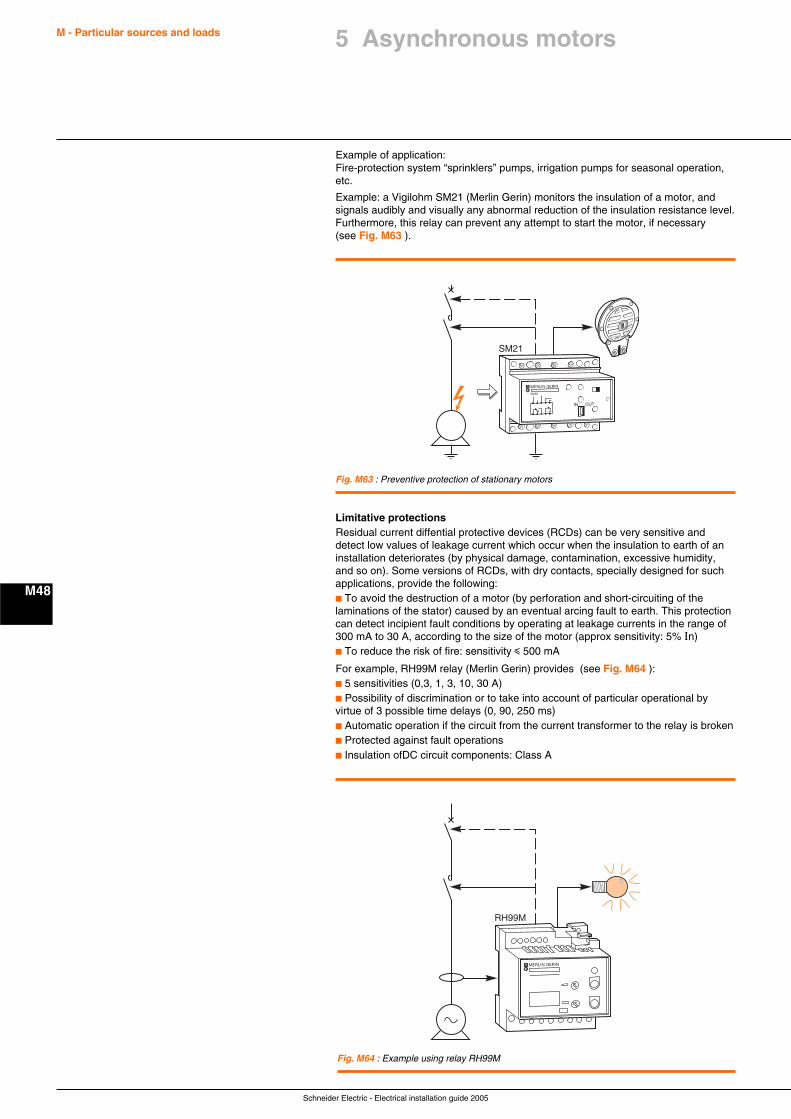
Schneider Electric - Electrical installation guide 2005
M - Particular sources and loads
M48
Example of application:Fire-protection system “sprinklers” pumps, irrigation pumps for seasonal operation,etc.
Example: a Vigilohm SM21 (Merlin Gerin) monitors the insulation of a motor, andsignals audibly and visually any abnormal reduction of the insulation resistance level.Furthermore, this relay can prevent any attempt to start the motor, if necessary(see Fig. M63 ).
SM21
MERLIN GERIN
SM20
IN OUT
Fig. M63 : Preventive protection of stationary motors
RH99M
MERLIN GERIN
Fig. M64 : Example using relay RH99M
Limitative protectionsResidual current diffential protective devices (RCDs) can be very sensitive anddetect low values of leakage current which occur when the insulation to earth of aninstallation deteriorates (by physical damage, contamination, excessive humidity,and so on). Some versions of RCDs, with dry contacts, specially designed for suchapplications, provide the following:c To avoid the destruction of a motor (by perforation and short-circuiting of thelaminations of the stator) caused by an eventual arcing fault to earth. This protectioncan detect incipient fault conditions by operating at leakage currents in the range of300 mA to 30 A, according to the size of the motor (approx sensitivity: 5% In)c To reduce the risk of fire: sensitivity i 500 mA
For example, RH99M relay (Merlin Gerin) provides (see Fig. M64 ):c 5 sensitivities (0,3, 1, 3, 10, 30 A)c Possibility of discrimination or to take into account of particular operational byvirtue of 3 possible time delays (0, 90, 250 ms)c Automatic operation if the circuit from the current transformer to the relay is brokenc Protected against fault operationsc Insulation ofDC circuit components: Class A
5 Asynchronous motors

Schneider Electric - Electrical installation guide 2005
M - Particular sources and loads
M49
5 Asynchronous motors
The importance of limiting voltage drop at the motor during start-upIn order that a motor starts and accelerates to its normal spped in the appropriatetime, the torque of the motor must exceed the load torque by at least 70%. However,the starting current is much greater than the full-load current of the motor. As a result,if the voltage drop is very high, the motor torque will be excessively reduced (motortorque is proportional to U2) and it will result, for extreme case, in failure to start.
Example:c With 400 V maintained at the terminals of a motor, its torque would be 2.1 timesthat of the load torquec For a voltage drop of 10% during start-up, the motor torque would be2.1 x 0.92 = 1.7 times the load torque, and the motor would accelerate to its ratedspeed normallyc For a voltage drop of 15% during start-up, the motor torque would be2.1 x 0.852 = 1.5 times the load torque, so that the motor starting time time wouldbe longer than normal
In general, a maximum allowable voltage drop of 10% Un is recommended duringstar-up of the motor.
5.4 Maximum rating of motors installed forconsumers supplied at LV
The disturbances caused on LV distribution networks during the start-up of largedirect-on-line AC motors can occasion considerable nuisance to neighbouringconsumers, so that most power-supply utilities have strict rules intended to limit suchdisturbances to tolerable levels. The amount of disturbance created by a given motordepends on the “strength” of the network, i.e. on the short-circuit fault level at thepoint concerned. The higher the fault level, the “stronger” the system and the lowerof the disturbance (principally volt-drop) experienced by neibouring consumers. Fordistribution networks in many countries, typical values of maximum allowable startingcurrents and corresponding maximum power ratings for direct-on-line motors areshown in Figures M65 and M66 below.
Type of motor Location Maximum starting current (A)Overhead-line network Underground-cable network
Single phase Dwellings 45 45Others 100 200
Three phase Dwellings 60 60Others 125 250
Location Type of motorSingle phase 230 V Three phase 400 V (kW) Direct-on-line starting Other methods
at full load (kW) of starting (kW)Dwellings 1.4 5.5 11Others Overhead 3 11 22
line networkUnderground 5.5 22 45cable network
Fig. M65 : Maximum permitted values of starting current for direct-on-line LV motors (230/400 V)
Since, even in areas supplied by one power utility only, “weak” areas of the networkexist as well as “strong” areas, it is always advisable to secure the agreement of thepower supplier before acquiring the motors for a new project.
Other (but generally more costly) alternative starting arrangements exist, whichreduce the large starting currents of direct-on-line motors to acceptable levels; forexample, star-delta starters, slip-ring motor, “soft start” electronic devices, etc.
5.5 Reactive-energy compensation (power-factorcorrection)The method to correct the power factor is indicated in chapter K.
Fig. M66 : Maximum permitted power ratings for LV direct-on-line starting motors
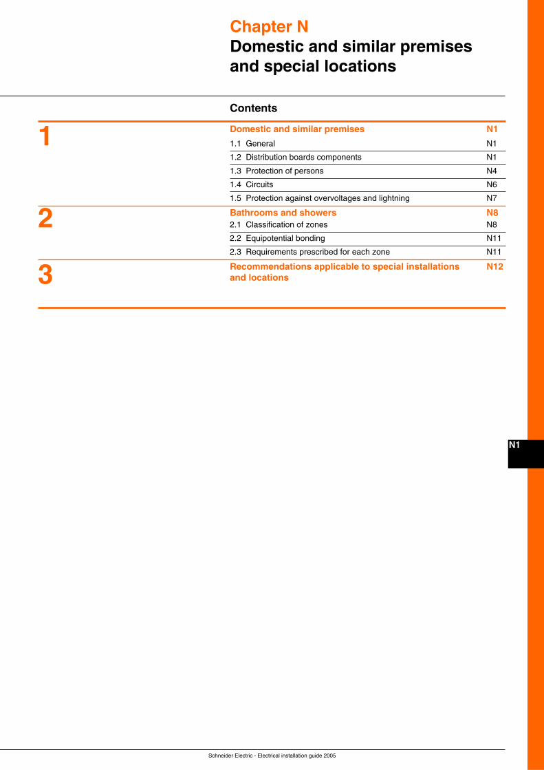
Schneider Electric - Electrical installation guide 2005
N1
Chapter NDomestic and similar premisesand special locations
Contents
Domestic and similar premises N1
1.1 General N1
1.2 Distribution boards components N1
1.3 Protection of persons N4
1.4 Circuits N6
1.5 Protection against overvoltages and lightning N7
Bathrooms and showers N82.1 Classification of zones N8
2.2 Equipotential bonding N11
2.3 Requirements prescribed for each zone N11
Recommendations applicable to special installations N12and locations3
2
1
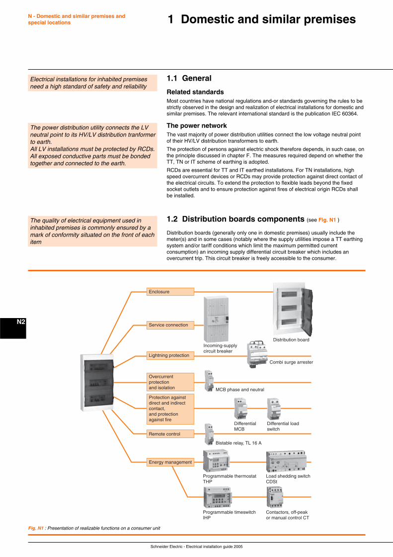
Schneider Electric - Electrical installation guide 2005
N - Domestic and similar premises andspecial locations
N2
1.1 General
Related standardsMost countries have national regulations and-or standards governing the rules to bestrictly observed in the design and realization of electrical installations for domestic andsimilar premises. The relevant international standard is the publication IEC 60364.
The power networkThe vast majority of power distribution utilities connect the low voltage neutral pointof their HV/LV distribution transformers to earth.
The protection of persons against electric shock therefore depends, in such case, onthe principle discussed in chapter F. The measures required depend on whether theTT, TN or IT scheme of earthing is adopted.
RCDs are essential for TT and IT earthed installations. For TN installations, highspeed overcurrent devices or RCDs may provide protection against direct contact ofthe electrical circuits. To extend the protection to flexible leads beyond the fixedsocket outlets and to ensure protection against fires of electrical origin RCDs shallbe installed.
1.2 Distribution boards components (see Fig. N1 )
Distribution boards (generally only one in domestic premises) usually include themeter(s) and in some cases (notably where the supply utilities impose a TT earthingsystem and/or tariff conditions which limit the maximum permitted currentconsumption) an incoming supply differential circuit breaker which includes anovercurrent trip. This circuit breaker is freely accessible to the consumer.
1 Domestic and similar premises
The quality of electrical equipment used ininhabited premises is commonly ensured by amark of conformity situated on the front of eachitem
The power distribution utility connects the LVneutral point to its HV/LV distribution tranformerto earth.All LV installations must be protected by RCDs.All exposed conductive parts must be bondedtogether and connected to the earth.
Electrical installations for inhabited premisesneed a high standard of safety and reliability
Fig. N1 : Presentation of realizable functions on a consumer unit
Distribution board
Combi surge arrester
Bistable relay, TL 16 A
Programmable thermostat THP
Load shedding switchCDSt
Programmable timeswitch IHP
Contactors, off-peakor manual control CT
DifferentialMCB
Differential loadswitch
Incoming-supplycircuit breaker
Enclosure
Remote control
Energy management
Service connection
Lightning protection
Overcurrentprotectionand isolation
Protection againstdirect and indirectcontact,and protectionagainst fire
MCB phase and neutral
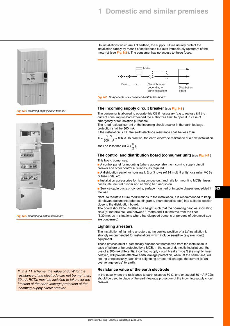
Schneider Electric - Electrical installation guide 2005
N3
On installations which are TN earthed, the supply utilities usually protect theinstallation simply by means of sealed fuse cut-outs immediately upstream of themeter(s) (see Fig. N2 ). The consumer has no access to these fuses.
1 Domestic and similar premises
If, in a TT scheme, the value of 80 W for theresistance of the electrode can not be met then,30 mA RCDs must be installed to take over thefunction of the earth leakage protection of theincoming supply circuit breaker
The incoming supply circuit breaker (see Fig. N3 )
The consumer is allowed to operate this CB if necessary (e.g to reclose it if thecurrent consumption bad exceeded the authorizes limit; to open it in case ofemergency or for isolation purposes).The rated residual current of the incoming circuit breaker in the earth leakageprotection shall be 300 mA.If the installation is TT, the earth electrode resistance shall be less than
R50 V
300 mA166 = = Ω . In practise, the earth electrode resistance of a new installation
shall be less than 80 Ω (R2
).
The control and distribution board (consumer unit) (see Fig. N4 )
This board comprises:c A control panel for mounting (where appropriate) the incoming supply circuitbreaker and other control auxiliaries, as requiredc A distribution panel for housing 1, 2 or 3 rows (of 24 multi 9 units) or similar MCBsor fuse units, etc.c Installation accessories for fixing conductors, and rails for mounting MCBs, fusesbases, etc, neutral busbar and earthing bar, and so onc Service cable ducts or conduits, surface mounted or in cable chases embedded inthe wall
Note: to facilitate future modifications to the installation, it is recommended to keepall relevant documents (photos, diagrams, characteristics, etc.) in a suitable locationclose to the distribution board.The board should be installed at a height such that the operating handles, indicatingdials (of meters) etc., are between 1 metre and 1.80 metres from the floor(1.30 metres in situations where handicapped persons or persons of advanced ageare concerned).
Lightning arrestersThe installation of lightning arresters at the service position of a LV installation isstrongly recommended for installations which include sensitive (e.g electronic)equipment.
These devices must automatically disconnect themselves from the installation incase of failure or be protected by a MCB. In the case of domestic installations, theuse of a 300 mA differential incoming supply circuit breaker type S (i.e slightly time-delayed) will provide effective earth leakage protection, while, at the same time, willnot trip unnecessarily each time a lightning arrester discharges the current (of anovervoltage-surge) to earth.
Resistance value of the earth electrodeIn the case where the resistance to earth exceeds 80 Ω, one or several 30 mA RCDsshould be used in place of the earth leakage protection of the incoming supply circuitbreaker.
Circuit breakerdepending onearthing system
Fuse … or …Distributionboard
Meter
Fig. N2 : Components of a control and distribution board
Fig. N3 : Incoming-supply circuit breaker
Fig. N4 : Control and distribution board
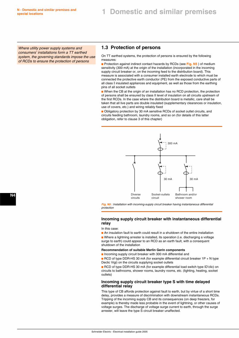
Schneider Electric - Electrical installation guide 2005
N - Domestic and similar premises andspecial locations
N4
1.3 Protection of persons
On TT earthed systems, the protection of persons is ensured by the followingmeasures:c Protection against indirect contact hazards by RCDs (see Fig. N5 ) of mediumsensitivity (300 mA) at the origin of the installation (incorporated in the incomingsupply circuit breaker or, on the incoming feed to the distribution board). Thismeasure is associated with a consumer installed earth electrode to which must beconnected the protective earth conductor (PE) from the exposed conductive parts ofall class I insulated appliances and equipment, as well as those from the earthingpins of all socket outletsc When the CB at the origin of an installation has no RCD protection, the protectionof persons shall be ensured by class II level of insulation on all circuits upstream ofthe first RCDs. In the case where the distribution board is metallic, care shall betaken that all live parts are double insulated (supplementary clearances or insulation,use of covers, etc.) and wiring reliably fixedc Obligatory protection by 30 mA sensitive RCDs of socket outlet circuits, andcircuits feeding bathroom, laundry rooms, and so on (for details of this latterobligation, refer to clause 3 of this chapter)
Where utility power supply systems andconsumers’ installations form a TT earthedsystem, the governing standards impose the useof RCDs to ensure the protection of persons
300 mA
30 mA 30 mA
Bathroom and/orshower room
Socket-outletscircuit
Diversecircuits
Fig. N5 : Installation with incoming-supply circuit breaker having instantaneous differentialprotection
Incoming supply circuit breaker with instantaneous differentialrelayIn this case:c An insulation fault to earth could result in a shutdown of the entire installationc Where a lightning arrester is installed, its operation (i.e. discharging a voltagesurge to earth) could appear to an RCD as an earth fault, with a consequentshutdown of the installation
Recommendation of suitable Merlin Gerin componentsc Incoming supply circuit breaker with 300 mA differential andc RCD of type DDR-HS 30 mA (for example differential circuit breaker 1P + N typeDeclic Vigi) on the circuits supplying socket outletsc RCD of type DDR-HS 30 mA (for example differential load switch type ID’clic) oncircuits to bathrooms, shower rooms, laundry rooms, etc. (lighting, heating, socketoutlets)
Incoming supply circuit breaker type S with time delayeddifferential relayThis type of CB affords protection against fault to earth, but by virtue of a short timedelay, provides a measure of discrimination with downstream instantaneous RCDs.Tripping of the incoming supply CB and its consequences (on deep freezers, forexample) is thereby made less probable in the event of lightning, or other causes ofvoltage surges. The discharge of voltage surge current to earth, through the surgearrester, will leave the type S circuit breaker unaffected.
1 Domestic and similar premises
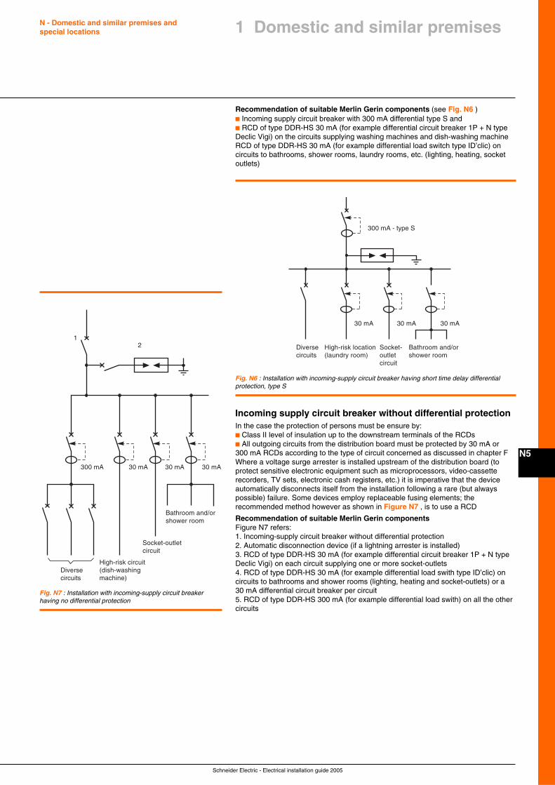
Schneider Electric - Electrical installation guide 2005
N - Domestic and similar premises andspecial locations
N5
1 Domestic and similar premises
Recommendation of suitable Merlin Gerin components (see Fig. N6 )c Incoming supply circuit breaker with 300 mA differential type S andc RCD of type DDR-HS 30 mA (for example differential circuit breaker 1P + N typeDeclic Vigi) on the circuits supplying washing machines and dish-washing machineRCD of type DDR-HS 30 mA (for example differential load switch type ID’clic) oncircuits to bathrooms, shower rooms, laundry rooms, etc. (lighting, heating, socketoutlets)
300 mA - type S
30 mA
Bathroom and/orshower room
Socket-outletcircuit
Diversecircuits
30 mA 30 mA
High-risk location(laundry room)
Fig. N6 : Installation with incoming-supply circuit breaker having short time delay differentialprotection, type S
Incoming supply circuit breaker without differential protectionIn the case the protection of persons must be ensure by:c Class II level of insulation up to the downstream terminals of the RCDsc All outgoing circuits from the distribution board must be protected by 30 mA or300 mA RCDs according to the type of circuit concerned as discussed in chapter FWhere a voltage surge arrester is installed upstream of the distribution board (toprotect sensitive electronic equipment such as microprocessors, video-cassetterecorders, TV sets, electronic cash registers, etc.) it is imperative that the deviceautomatically disconnects itself from the installation following a rare (but alwayspossible) failure. Some devices employ replaceable fusing elements; therecommended method however as shown in Figure N7 , is to use a RCD
Recommendation of suitable Merlin Gerin componentsFigure N7 refers:1. Incoming-supply circuit breaker without differential protection2. Automatic disconnection device (if a lightning arrester is installed)3. RCD of type DDR-HS 30 mA (for example differential circuit breaker 1P + N typeDeclic Vigi) on each circuit supplying one or more socket-outlets4. RCD of type DDR-HS 30 mA (for example differential load swith type ID’clic) oncircuits to bathrooms and shower rooms (lighting, heating and socket-outlets) or a30 mA differential circuit breaker per circuit5. RCD of type DDR-HS 300 mA (for example differential load swith) on all the othercircuits
Bathroom and/orshower room
Socket-outletcircuit
300 mA 30 mA 30 mA 30 mA
High-risk circuit(dish-washingmachine)
Diversecircuits
21
Fig. N7 : Installation with incoming-supply circuit breakerhaving no differential protection
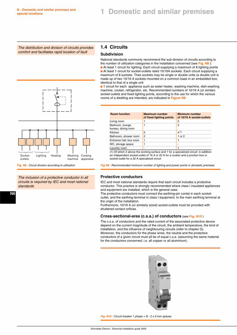
Schneider Electric - Electrical installation guide 2005
N - Domestic and similar premises andspecial locations
N6
1.4 CircuitsSubdivisionNational standards commonly recommend the sub-division of circuits according tothe number of utilization categories in the installation concerned (see Fig. N8 ):c At least 1 circuit for lighting. Each circuit supplying a maximum of 8 lighting pointsc At least 1 circuit for socket-outlets rated 10/16A sockets. Each circuit supplying amaximum of 8 sockets. Thee sockets may be single or double units (a double unit ismade up of two 10/16 A sockets mounted on a common base in an embedded box,identical to that of a single unitc 1 circuit for each appliance such as water heater, washing machine, dish-washingmachine, cooker, refrigerator, etc. Recommended numbers of 10/16 A (or similar)socket-outlets and fixed lighting points, according to the use for which the variousrooms of a dwelling are intended, are indicated in Figure N9
The distribution and division of circuits providescomfort and facilitates rapid location of fault
Cookingapparatus
Washingmachine
Lighting HeatingSocket-outlets
Fig. N8 : Circuit division according to utilization Fig N9 : Recommended minimum number of lighting and power points in domestic premises
Protective conductorsIEC and most national standards require that each circuit includes a protectiveconductor. This practice is strongly recommended where class I insulated appliancesand equipment are installed, which is the general case.The protective conductors must connect the earthing-pin contat in each socket-outlet, and the earthing terminal in class I equipment, to the main earthing terminal atthe origin of the installation.Furthermore, 10/16 A (or similarly sized) socket-outlets must be provided withshuttered contact orifices.
Cross-sectional-area (c.s.a.) of conductors (see Fig. N10 )
The c.s.a. of conductors and the rated current of the associated protective devicedepend on the current magnitude of the circuit, the ambient temperature, the kind ofinstallation, and the influence of neighbouring circuits (refer to chapter G)Moreover, the conductors for the phase wires, the neutral and the protectiveconductors of a given circuit must all be of equal c.s.a. (assuming the same materialfor the conductors concerned, i.e. all copper or all aluminium).
The inclusion of a protective conductor in allcircuits is required by IEC and most nationalstandards
Fig. N10 : Circuit breaker 1 phase + N - 2 x 9 mm spaces
Room function Maximum number Minimum numberof fixed lighting points of 10/16 A socket-outlets
Living room 1 5Bedroom, lounge, 1 3bureau, dining roomKitchen 2 4 (1)
Bathroom, shower room 2 1 or 2Entrance hall, box room 1 1WC, storage space 1 -Laundry room - 1(1) Of which 2 above the working surface and 1 for a specialized circuit: in additionan independent socket-outlet of 16 A or 20 A for a cooker and a junction box orsocket-outlet for a 32 A specialized circuit
1 Domestic and similar premises
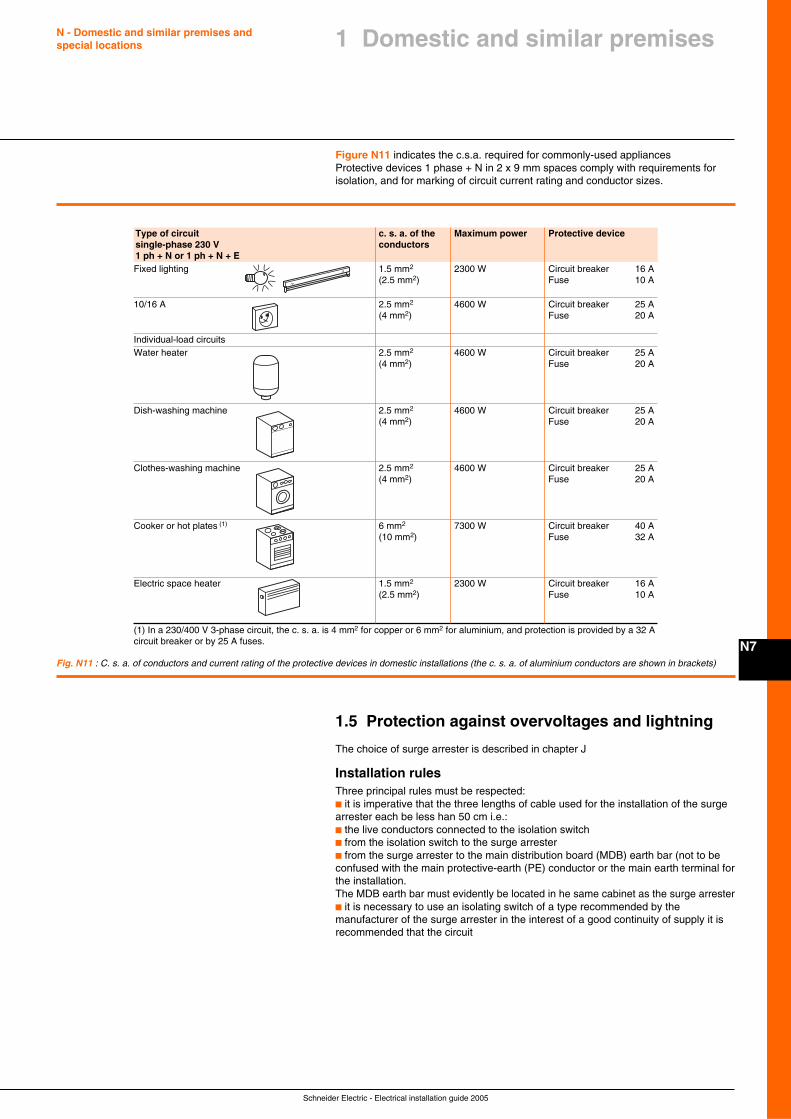
Schneider Electric - Electrical installation guide 2005
N - Domestic and similar premises andspecial locations
N7
Figure N11 indicates the c.s.a. required for commonly-used appliancesProtective devices 1 phase + N in 2 x 9 mm spaces comply with requirements forisolation, and for marking of circuit current rating and conductor sizes.
1.5 Protection against overvoltages and lightning
The choice of surge arrester is described in chapter J
Installation rulesThree principal rules must be respected:c it is imperative that the three lengths of cable used for the installation of the surgearrester each be less han 50 cm i.e.:c the live conductors connected to the isolation switchc from the isolation switch to the surge arresterc from the surge arrester to the main distribution board (MDB) earth bar (not to beconfused with the main protective-earth (PE) conductor or the main earth terminal forthe installation.The MDB earth bar must evidently be located in he same cabinet as the surge arresterc it is necessary to use an isolating switch of a type recommended by themanufacturer of the surge arrester in the interest of a good continuity of supply it isrecommended that the circuit
Type of circuit c. s. a. of the Maximum power Protective devicesingle-phase 230 V conductors1 ph + N or 1 ph + N + EFixed lighting 1.5 mm2 2300 W Circuit breaker 16 A
(2.5 mm2) Fuse 10 A
10/16 A 2.5 mm2 4600 W Circuit breaker 25 A(4 mm2) Fuse 20 A
Individual-load circuitsWater heater 2.5 mm2 4600 W Circuit breaker 25 A
(4 mm2) Fuse 20 A
Dish-washing machine 2.5 mm2 4600 W Circuit breaker 25 A(4 mm2) Fuse 20 A
Clothes-washing machine 2.5 mm2 4600 W Circuit breaker 25 A(4 mm2) Fuse 20 A
Cooker or hot plates (1) 6 mm2 7300 W Circuit breaker 40 A(10 mm2) Fuse 32 A
Electric space heater 1.5 mm2 2300 W Circuit breaker 16 A(2.5 mm2) Fuse 10 A
(1) In a 230/400 V 3-phase circuit, the c. s. a. is 4 mm2 for copper or 6 mm2 for aluminium, and protection is provided by a 32 Acircuit breaker or by 25 A fuses.
Fig. N11 : C. s. a. of conductors and current rating of the protective devices in domestic installations (the c. s. a. of aluminium conductors are shown in brackets)
1 Domestic and similar premises
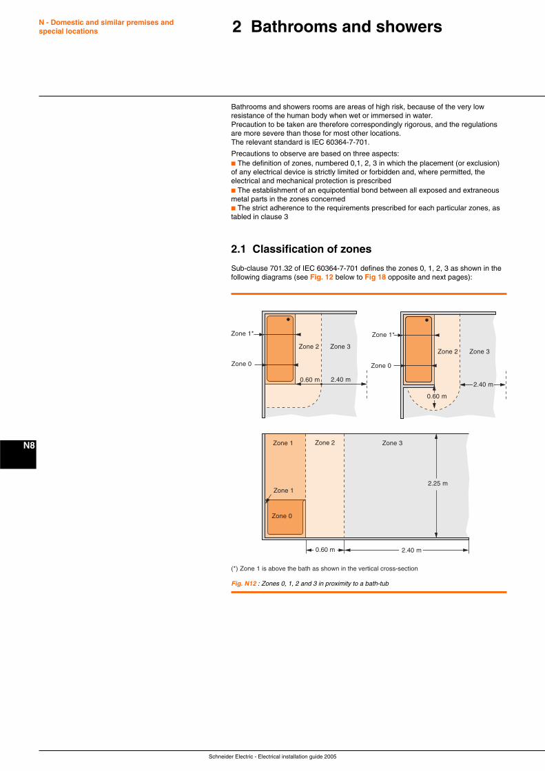
Schneider Electric - Electrical installation guide 2005
N - Domestic and similar premises andspecial locations
N8
Bathrooms and showers rooms are areas of high risk, because of the very lowresistance of the human body when wet or immersed in water.Precaution to be taken are therefore correspondingly rigorous, and the regulationsare more severe than those for most other locations.The relevant standard is IEC 60364-7-701.
Precautions to observe are based on three aspects:c The definition of zones, numbered 0,1, 2, 3 in which the placement (or exclusion)of any electrical device is strictly limited or forbidden and, where permitted, theelectrical and mechanical protection is prescribedc The establishment of an equipotential bond between all exposed and extraneousmetal parts in the zones concernedc The strict adherence to the requirements prescribed for each particular zones, astabled in clause 3
2.1 Classification of zones
Sub-clause 701.32 of IEC 60364-7-701 defines the zones 0, 1, 2, 3 as shown in thefollowing diagrams (see Fig. 12 below to Fig 18 opposite and next pages):
2 Bathrooms and showers
Fig. N12 : Zones 0, 1, 2 and 3 in proximity to a bath-tub
Zone 1*
(*) Zone 1 is above the bath as shown in the vertical cross-section
Zone 0
Zone 2 Zone 3
0.60 m 2.40 m
Zone 1*
Zone 2 Zone 3
0.60 m
2.40 m
Zone 0
Zone 0
Zone 1
Zone 3Zone 2
0.60 m
2.25 m
Zone 1
2.40 m
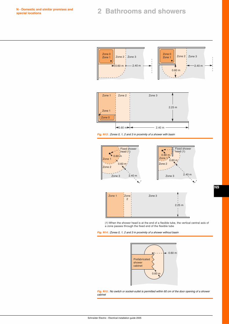
Schneider Electric - Electrical installation guide 2005
N - Domestic and similar premises andspecial locations
N9
2 Bathrooms and showers
Zone 2
Zone 3 Zone 3
0.60 m
2.25 m
Zone 2
2.40 m
Zone 0Zone 1
Zone 0Zone 1 Zone 2
0.60 m
2.40 m
Zone 1 Zone 3
2.40 m0.60 m
Zone 1
Zone 0
Fig. N13 : Zones 0, 1, 2 and 3 in proximity of a shower with basin
(1) When the shower head is at the end of a flexible tube, the vertical central axis ofa zone passes through the fixed end of the flexible tube
Zone 2
2.25 m
Zone 1
Zone 3
2.40 m
0.60 m
Zone 1
Zone2
Zone 3Zone 3
Zone 2
Zone 1
2.40 m
0.60 m
0.60 m 0.60 m
Fixed showerhead (1)
Fixed showerhead (1)
Fig. N14 : Zones 0, 1, 2 and 3 in proximity of a shower without basin
Prefabricatedshowercabinet
0.60 m
0.60 m
Fig. N15 : No switch or socket-outlet is permitted within 60 cm of the door opening of a showercabinet
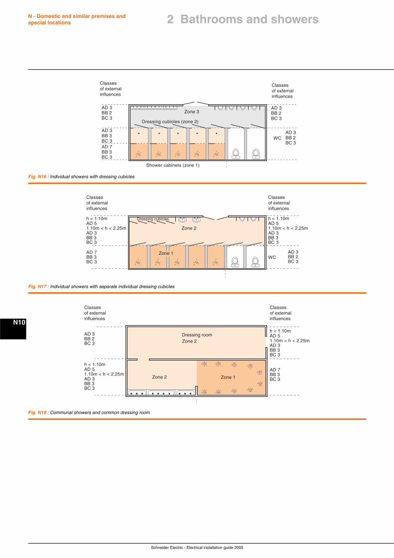
Schneider Electric - Electrical installation guide 2005
N - Domestic and similar premises andspecial locations
N10
Fig. N16 : Individual showers with dressing cubicles
Zone 3AD 3BB 2BC 3
AD 3BB 2BC 3
Shower cabinets (zone 1)
Dressing cubicles (zone 2)
Classesof externalinfluences
WC
Classesof externalinfluences
AD 3BB 2BC 3
AD 3BB 3BC 3AD 7BB 3BC 3
Zone 2
AD 3BB 2BC 3
WC
Classesof externalinfluences
AD 7BB 3BC 3
Classesof externalinfluences
h < 1.10m
1.10m < h < 2.25mAD 3BB 3BC 3
Zone 1
Dressing cubiclesAD 5
h < 1.10m
1.10m < h < 2.25mAD 3BB 3BC 3
AD 5
Fig. N17 : Individual showers with separate individual dressing cubicles
Fig. N18 : Communal showers and common dressing room
Zone 2
AD 7BB 3BC 3
Classesof externalinfluences
AD 3BB 2BC 3
Classesof externalinfluences
Zone 2
Dressing room
Zone 1
h < 1.10m
1.10m < h < 2.25mAD 3BB 3BC 3
AD 5
h < 1.10m
1.10m < h < 2.25mAD 3BB 3BC 3
AD 5
2 Bathrooms and showers
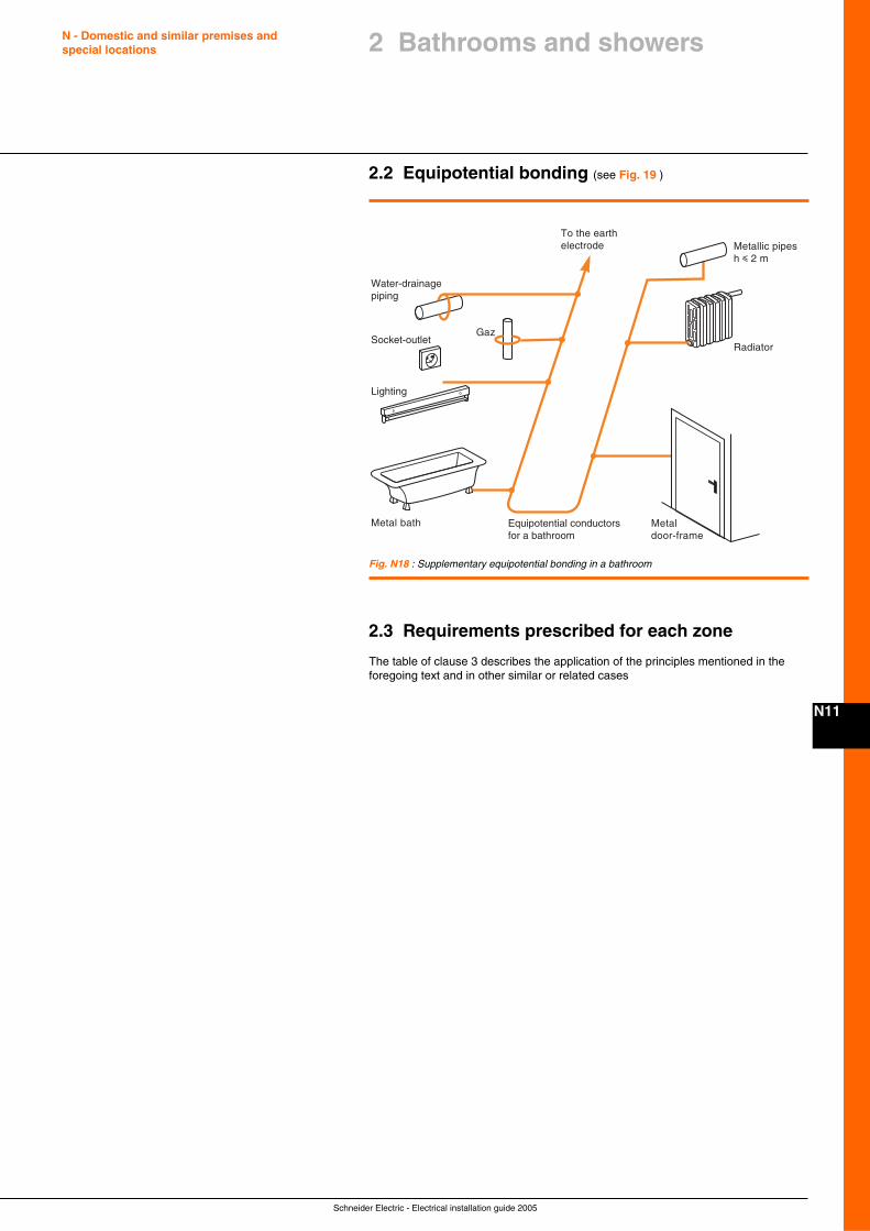
Schneider Electric - Electrical installation guide 2005
N - Domestic and similar premises andspecial locations
N11
2 Bathrooms and showers
2.2 Equipotential bonding (see Fig. 19 )
Metallic pipesh i 2 m
Radiator
Metaldoor-frame
Metal bath Equipotential conductorsfor a bathroom
Lighting
Gaz
Water-drainagepiping
Socket-outlet
To the earthelectrode
Fig. N18 : Supplementary equipotential bonding in a bathroom
2.3 Requirements prescribed for each zone
The table of clause 3 describes the application of the principles mentioned in theforegoing text and in other similar or related cases
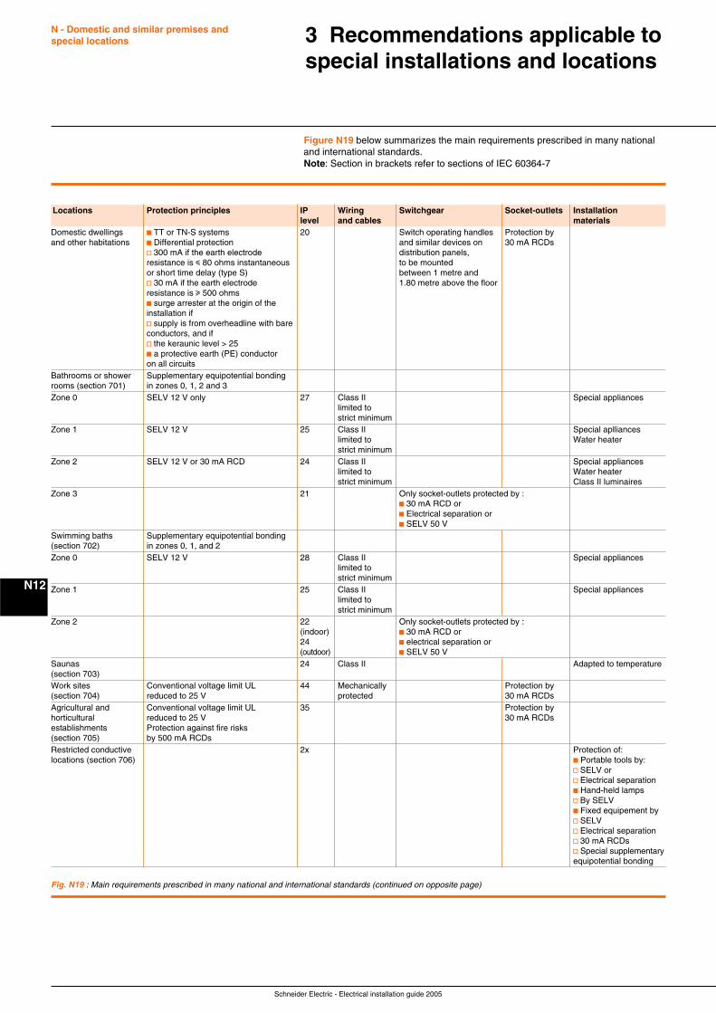
Schneider Electric - Electrical installation guide 2005
N - Domestic and similar premises andspecial locations
N12
3 Recommendations applicable tospecial installations and locations
Fig. N19 : Main requirements prescribed in many national and international standards (continued on opposite page)
Figure N19 below summarizes the main requirements prescribed in many nationaland international standards.Note: Section in brackets refer to sections of IEC 60364-7
Locations Protection principles IP Wiring Switchgear Socket-outlets Installationlevel and cables materials
Domestic dwellings c TT or TN-S systems 20 Switch operating handles Protection byand other habitations c Differential protection and similar devices on 30 mA RCDs
v 300 mA if the earth electrode distribution panels,resistance is i 80 ohms instantaneous to be mountedor short time delay (type S) between 1 metre andv 30 mA if the earth electrode 1.80 metre above the floorresistance is u 500 ohmsc surge arrester at the origin of theinstallation ifv supply is from overheadline with bareconductors, and ifv the keraunic level > 25c a protective earth (PE) conductoron all circuits
Bathrooms or shower Supplementary equipotential bondingrooms (section 701) in zones 0, 1, 2 and 3Zone 0 SELV 12 V only 27 Class II Special appliances
limited tostrict minimum
Zone 1 SELV 12 V 25 Class II Special apllianceslimited to Water heaterstrict minimum
Zone 2 SELV 12 V or 30 mA RCD 24 Class II Special applianceslimited to Water heaterstrict minimum Class II luminaires
Zone 3 21 Only socket-outlets protected by :c 30 mA RCD orc Electrical separation orc SELV 50 V
Swimming baths Supplementary equipotential bonding(section 702) in zones 0, 1, and 2Zone 0 SELV 12 V 28 Class II Special appliances
limited tostrict minimum
Zone 1 25 Class II Special applianceslimited tostrict minimum
Zone 2 22 Only socket-outlets protected by :(indoor) c 30 mA RCD or24 c electrical separation or(outdoor) c SELV 50 V
Saunas 24 Class II Adapted to temperature(section 703)Work sites Conventional voltage limit UL 44 Mechanically Protection by(section 704) reduced to 25 V protected 30 mA RCDsAgricultural and Conventional voltage limit UL 35 Protection byhorticultural reduced to 25 V 30 mA RCDsestablishments Protection against fire risks(section 705) by 500 mA RCDsRestricted conductive 2x Protection of:locations (section 706) c Portable tools by:
v SELV orv Electrical separationc Hand-held lampsv By SELVc Fixed equipement byv SELVv Electrical separationv 30 mA RCDsv Special supplementaryequipotential bonding
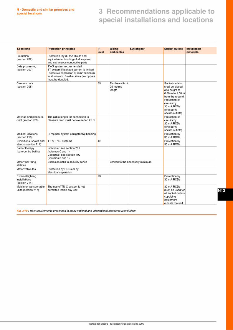
Schneider Electric - Electrical installation guide 2005
N - Domestic and similar premises andspecial locations
N13
3 Recommendations applicable tospecial installations and locations
Locations Protection principles IP Wiring Switchgear Socket-outlets Installationlevel and cables materials
Fountains Protection by 30 mA RCDs and(section 702) equipotential bonding of all exposed
and extraneous conductive partsData processing TV-S system recommended(section 707) TT system if leakage current is limited.
Protective conductor 10 mm2 minimumin aluminium. Smaller sizes (in copper)must be doubled.
Caravan park 55 Flexible cable of Socket-outlets(section 708) 25 metres shall be placed
length at a height of0.80 m to 1.50 mfrom the ground.Protection ofcircuits by30 mA RCDs(one per 6socket-outlets)
Marinas and pleasure The cable length for connection to Protection ofcraft (section 709) pleasure craft must not exceeded 25 m circuits by
30 mA RCDs(one per 6socket-outlets)
Medical locations IT medical system equipotential bonding Protection by(section 710) 30 mA RCDsExhibitions, shows and TT or TN-S systems 4x Protection bystands (section 711) 30 mA RCDsBalneotherapy Individual: see section 701(cure-centre baths) (volumes 0 and 1)
Collective: see section 702(volumes 0 and 1)
Motor-fuel filling Explosion risks in security zones Limited to the necessary minimumstationsMotor vehicules Protection by RCDs or by
electrical separationExternal lighting 23 Protection byinstallations 30 mA RCDs(section 714)Mobile or transportable The use of TN-C system is not 30 mA RCDsunits (section 717) permitted inside any unit must be used for
all socket-outletssupplyingequipmentoutside the unit
Fig. N19 : Main requirements prescribed in many national and international standards (concluded)
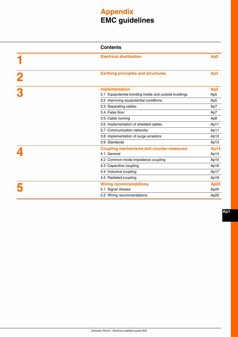
Schneider Electric - Electrical installation guide 2005
Ap1
AppendixEMC guidelines
Contents
Electrical distribution Ap2
Earthing principles and structures Ap3
Implementation Ap53.1 Equipotential bonding inside and outside buildings Ap5
3.2 Improving equipotential conditions Ap5
3.3 Separating cables Ap7
3.4 False floor Ap7
3.5 Cable running Ap8
3.6 Implementation of shielded cables Ap11
3.7 Communication networks Ap11
3.8 Implementation of surge arrestors Ap12
3.9 Standards Ap13
Coupling mechanisms and counter-measures Ap144.1 General Ap14
4.2 Common-mode impedance coupling Ap15
4.3 Capacitive coupling Ap16
4.4 Inductive coupling Ap17
4.5 Radiated coupling Ap18
Wiring recommendations Ap205.1 Signal classes Ap20
5.2 Wiring recommendations Ap20
123
4
5
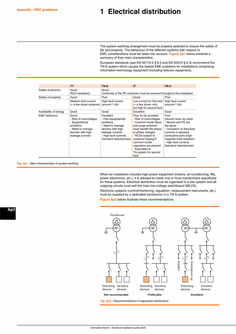
Schneider Electric - Electrical installation guide 2005
Appendix - EMC guidelines
Ap2
1 Electrical distribution
The system earthing arrangement must be properly selected to ensure the safety oflife and property. The behaviour of the different systems with respect toEMC considerations must be taken into account. Figure Ap1 below presents asummary of their main characteristics.
European standards (see EN 50174-2 § 6.4 and EN 50310 § 6.3) recommend theTN-S system which causes the fewest EMC problems for installations comprisinginformation-technology equipment (including telecom equipment).
Fig. Ap1 : Main characteristics of system earthing
When an installation includes high-power equipment (motors, air-conditioning, lifts,power electronics, etc.), it is advised to install one or more transformers specificallyfor these systems. Electrical distribution must be organised in a star system and alloutgoing circuits must exit the main low-voltage switchboard (MLVS).
Electronic systems (control/monitoring, regulation, measurement instruments, etc.)must be supplied by a dedicated transformer in a TN-S system.
Figure Ap2 below illustrate these recommendations.
Disturbingdevices
Sensitivedevices
Transformer
Not recommended Preferable Excellent
Disturbingdevices
Sensitivedevices
Disturbingdevices
Ligh
ting
Air
cond
ition
ing
Sensitivedevices
Fig. Ap2 : Recommendations of separated distributions
TT TN-S IT TN-CSafety of persons Good Good
RCD mandatory Continuity of the PE conductor must be ensured throughout the installationSafety of property Good Poor Good Poor
Medium fault current High fault current Low current for first fault High fault current(< a few dozen amperes) (around 1 kA) (< a few dozen mA), (around 1 kA)
but high for second faultAvailability of energy Good Good Excellent GoodEMC behaviour Good Excellent Poor (to be avoided) Poor
- Risk of overvoltages - Few equipotential - Risk of overvoltages (should never be used)- Equipotential problems - Common-mode filters - Neutral and PE areproblems - Need to manage and surge arrestors the same- Need to manage devices with high must handle the phase- - Circulation of disturbeddevices with high leakage currents to-phase voltages currents in exposedleakage currents - High fault currents - RCDs subject to conductive parts (high
(transient disturbances) nuisance tripping if magnetic-field radiation)common-mode - High fault currentscapacitors are present (transient disturbances)- Equivalent toTN system for secondfault

Schneider Electric - Electrical installation guide 2005
Appendix - EMC guidelines
Ap3
2 Earthing principles andstructures
This section deals with the earthing and equipotential bonding of information-technologydevices and other similar devices requiring interconnections for signalling purposes.
Earthing networks are designed to fulfil a number of functions. They can beindependent or operate together to provide one or more of the following:c Safety of persons with respect to electrical hazardsc Protection of equipment with respect to electrical hazardsc A reference value for reliable, high-quality signalsc Satisfactory EMC performance
The system earthing arrangement is generally designed and installed in view ofobtaining a low impedance capable of diverting fault currents and HF currents awayfrom electronic devices and systems. There are different types of system earthingarrangements and some require that specific conditions be met. These conditionsare not always met in typical installations. The recommendations presented in thissection are intended for such installations.
For professional and industrial installations, a common bonding network (CBN) maybe useful to ensure better EMC performance with respect to the following points:c Digital systems and new technologiesc Compliance with the EMC requirements of EEC 89/336 (emission and immunity)c The wide number of electrical applicationsc A high level of system safety and security, as well as reliability and/or availability
For residential premises, however, where the use of electrical devices is limited, anisolated bonding network (IBN) or, even better, a mesh IBN may be a solution.
It is now recognised that independent, dedicated earth electrodes, each serving aseparate earthing network, are a solution that is not acceptable in terms of EMC, butalso represent a serious safety hazard. In certain countries, the national buildingcodes forbid such systems.
Use of a separate “clean” earthing network for electronics and a “dirty” earthingnetwork for energy is not recommended in view of obtaining correct EMC, evenwhen a single electrode is used (see Fig. Ap3 and Fig. Ap4 ). In the event of alightning strike, a fault current or HF disturbances as well as transient currents willflow in the installation. Consequently, transient voltages will be created and result infailures or damage to the installation. If installation and maintenance are carried outproperly, this approach may be dependable (at power frequencies), but it is generallynot suitable for EMC purposes and is not recommended for general use.
Fig. Ap3 : Independent earth electrodes, a solution generally not acceptable for safety and EMCreasons
Fig. Ap4 : Installation with a single earth electrode
"Clean"earthing network
Electricalearthing network
Surge arrestors
Separate earth electrodes
"Clean"earthing network
Electricalearthing network
Surge arrestors
Single earth electrode
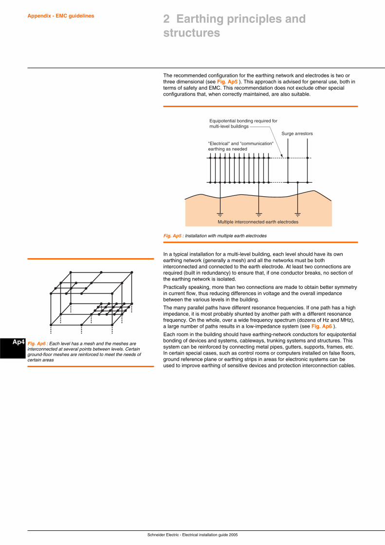
Schneider Electric - Electrical installation guide 2005
Appendix - EMC guidelines
Ap4
The recommended configuration for the earthing network and electrodes is two orthree dimensional (see Fig. Ap5 ). This approach is advised for general use, both interms of safety and EMC. This recommendation does not exclude other specialconfigurations that, when correctly maintained, are also suitable.
Fig. Ap5 : Installation with multiple earth electrodes
Fig. Ap6 : Each level has a mesh and the meshes areinterconnected at several points between levels. Certainground-floor meshes are reinforced to meet the needs ofcertain areas
2 Earthing principles andstructures
Equipotential bonding required formulti-level buildings
"Electrical" and "communication" earthing as needed
Surge arrestors
Multiple interconnected earth electrodes
In a typical installation for a multi-level building, each level should have its ownearthing network (generally a mesh) and all the networks must be bothinterconnected and connected to the earth electrode. At least two connections arerequired (built in redundancy) to ensure that, if one conductor breaks, no section ofthe earthing network is isolated.
Practically speaking, more than two connections are made to obtain better symmetryin current flow, thus reducing differences in voltage and the overall impedancebetween the various levels in the building.
The many parallel paths have different resonance frequencies. If one path has a highimpedance, it is most probably shunted by another path with a different resonancefrequency. On the whole, over a wide frequency spectrum (dozens of Hz and MHz),a large number of paths results in a low-impedance system (see Fig. Ap6 ).
Each room in the building should have earthing-network conductors for equipotentialbonding of devices and systems, cableways, trunking systems and structures. Thissystem can be reinforced by connecting metal pipes, gutters, supports, frames, etc.In certain special cases, such as control rooms or computers installed on false floors,ground reference plane or earthing strips in areas for electronic systems can beused to improve earthing of sensitive devices and protection interconnection cables.
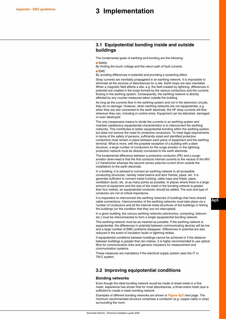
Schneider Electric - Electrical installation guide 2005
Appendix - EMC guidelines
Ap5
3 Implementation
3.1 Equipotential bonding inside and outsidebuildings
The fundamental goals of earthing and bonding are the following:
c SafetyBy limiting the touch voltage and the return path of fault currents
c EMCBy avoiding differences in potential and providing a screening effect.
Stray currents are inevitably propagated in an earthing network. It is impossible toeliminate all the sources of disturbances for a site. Earth loops are also inevitable.When a magnetic field affects a site, e.g. the field created by lightning, differences inpotential are created in the loops formed by the various conductors and the currentsflowing in the earthing system. Consequently, the earthing network is directlyaffected by any counter-measures taken outside the building.
As long as the currents flow in the earthing system and not in the electronic circuits,they do no damage. However, when earthing networks are not equipotential, e.g.when they are star connected to the earth electrode, the HF stray currents will flowwherever they can, including in control wires. Equipment can be disturbed, damagedor even destroyed.
The only inexpensive means to divide the currents in an earthing system andmaintain satisfactory equipotential characteristics is to interconnect the earthingnetworks. This contributes to better equipotential bonding within the earthing system,but does not remove the need for protective conductors. To meet legal requirementsin terms of the safety of persons, sufficiently sized and identified protectiveconductors must remain in place between each piece of equipment and the earthingterminal. What is more, with the possible exception of a building with a steelstructure, a large number of conductors for the surge-arrestor or the lightning-protection network must be directly connected to the earth electrode.
The fundamental difference between a protective conductor (PE) and a surge-arrestor down-lead is that the first conducts internal currents to the neutral of the MV/LV transformer whereas the second carries external current (from outside theinstallation) to the earth electrode.
In a building, it is advised to connect an earthing network to all accessibleconducting structures, namely metal beams and door frames, pipes, etc. It isgenerally sufficient to connect metal trunking, cable trays and lintels, pipes,ventilation ducts, etc. at as many points as possible. In places where there is a largeamount of equipment and the size of the mesh in the bonding network is greaterthan four metres, an equipotential conductor should be added. The size and type ofconductor are not of critical importance.
It is imperative to interconnect the earthing networks of buildings that have sharedcable connections. Interconnection of the earthing networks must take place via anumber of conductors and all the internal metal structures of the buildings or linkingthe buildings (on the condition that they are not interrupted).
In a given building, the various earthing networks (electronics, computing, telecom,etc.) must be interconnected to form a single equipotential bonding network.
This earthing-network must be as meshed as possible. If the earthing network isequipotential, the differences in potential between communicating devices will be lowand a large number of EMC problems disappear. Differences in potential are alsoreduced in the event of insulation faults or lightning strikes.
If equipotential conditions between buildings cannot be achieved or if the distancebetween buildings is greater than ten metres, it is highly recommended to use opticalfibre for communication links and galvanic insulators for measurement andcommunication systems.
These measures are mandatory if the electrical supply system uses the IT orTN-C system.
3.2 Improving equipotential conditions
Bonding networksEven though the ideal bonding network would be made of sheet metal or a finemesh, experience has shown that for most disturbances, a three-metre mesh size issufficient to create a mesh bonding network.
Examples of different bonding networks are shown in Figure Ap7 next page. Theminimum recommended structure comprises a conductor (e.g. copper cable or strip)surrounding the room.
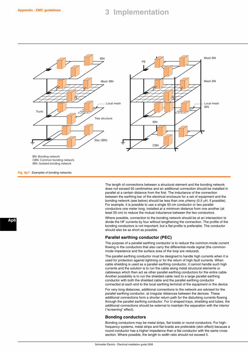
Schneider Electric - Electrical installation guide 2005
Appendix - EMC guidelines
Ap6
Fig. Ap7 : Examples of bonding networks
Trunk
IBN
IBN
BN: Bonding networkCBN: Common bonding networkIBN: Isolated bonding network
CBN
Star (IBN)
PE
Mesh IBN
Mesh BN
Mesh BN
Local mesh Local meshIBN
Tree structure
The length of connections between a structural element and the bonding networkdoes not exceed 50 centimetres and an additional connection should be installed inparallel at a certain distance from the first. The inductance of the connectionbetween the earthing bar of the electrical enclosure for a set of equipment and thebonding network (see below) should be less than one µHenry (0.5 µH, if possible).For example, it is possible to use a single 50 cm conductor or two parallelconductors one meter long, installed at a minimum distance from one another (atleast 50 cm) to reduce the mutual inductance between the two conductors.
Where possible, connection to the bonding network should be at an intersection todivide the HF currents by four without lengthening the connection. The profile of thebonding conductors is not important, but a flat profile is preferable. The conductorshould also be as short as possible.
Parallel earthing conductor (PEC)The purpose of a parallel earthing conductor is to reduce the common-mode currentflowing in the conductors that also carry the differential-mode signal (the common-mode impedance and the surface area of the loop are reduced).
The parallel earthing conductor must be designed to handle high currents when it isused for protection against lightning or for the return of high fault currents. Whencable shielding is used as a parallel earthing conductor, it cannot handle such highcurrents and the solution is to run the cable along metal structural elements orcableways which then act as other parallel earthing conductors for the entire cable.Another possibility is to run the shielded cable next to a large parallel earthingconductor with both the shielded cable and the parallel earthing conductorconnected at each end to the local earthing terminal of the equipment or the device.
For very long distances, additional connections to the network are advised for theparallel earthing conductor, at irregular distances between the devices. Theseadditional connections form a shorter return path for the disturbing currents flowingthrough the parallel earthing conductor. For U-shaped trays, shielding and tubes, theadditional connections should be external to maintain the separation with the interior(“screening” effect).
Bonding conductorsBonding conductors may be metal strips, flat braids or round conductors. For high-frequency systems, metal strips and flat braids are preferable (skin effect) because around conductor has a higher impedance than a flat conductor with the same crosssection. Where possible, the length to width ratio should not exceed 5.
3 Implementation
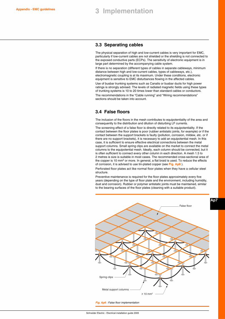
Schneider Electric - Electrical installation guide 2005
Appendix - EMC guidelines
Ap7
3 Implementation
3.3 Separating cables
The physical separation of high and low-current cables is very important for EMC,particularly if low-current cables are not shielded or the shielding is not connected tothe exposed conductive parts (ECPs). The sensitivity of electronic equipment is inlarge part determined by the accompanying cable system.
If there is no separation (different types of cables in separate cableways, minimumdistance between high and low-current cables, types of cableways, etc.),electromagnetic coupling is at its maximum. Under these conditions, electronicequipment is sensitive to EMC disturbances flowing in the affected cables.
Use of busbar trunking systems such as Canalis or busbar ducts for high powerratings is strongly advised. The levels of radiated magnetic fields using these typesof trunking systems is 10 to 20 times lower than standard cables or conductors.
The recommendations in the “Cable running” and “Wiring recommendations”sections should be taken into account.
3.4 False floors
The inclusion of the floors in the mesh contributes to equipotentiality of the area andconsequently to the distribution and dilution of disturbing LF currents.
The screening effect of a false floor is directly related to its equipotentiality. If thecontact between the floor plates is poor (rubber antistatic joints, for example) or if thecontact between the support brackets is faulty (pollution, corrosion, mildew, etc. or ifthere are no support brackets), it is necessary to add an equipotential mesh. In thiscase, it is sufficient to ensure effective electrical connections between the metalsupport columns. Small spring clips are available on the market to connect the metalcolumns to the equipotential mesh. Ideally, each column should be connected, but itis often sufficient to connect every other column in each direction. A mesh 1.5 to2 metres is size is suitable in most cases. The recommended cross-sectional area ofthe copper is 10 mm2 or more. In general, a flat braid is used. To reduce the effectsof corrosion, it is advised to use tin-plated copper (see Fig. Ap8 ).
Perforated floor plates act like normal floor plates when they have a cellular steelstructure.
Preventive maintenance is required for the floor plates approximately every fiveyears (depending on the type of floor plate and the environment, including humidity,dust and corrosion). Rubber or polymer antistatic joints must be maintained, similarto the bearing surfaces of the floor plates (cleaning with a suitable product).
False floor
u 10 mm2
Metal support columns
Spring clips
Fig. Ap8 : False floor implementation
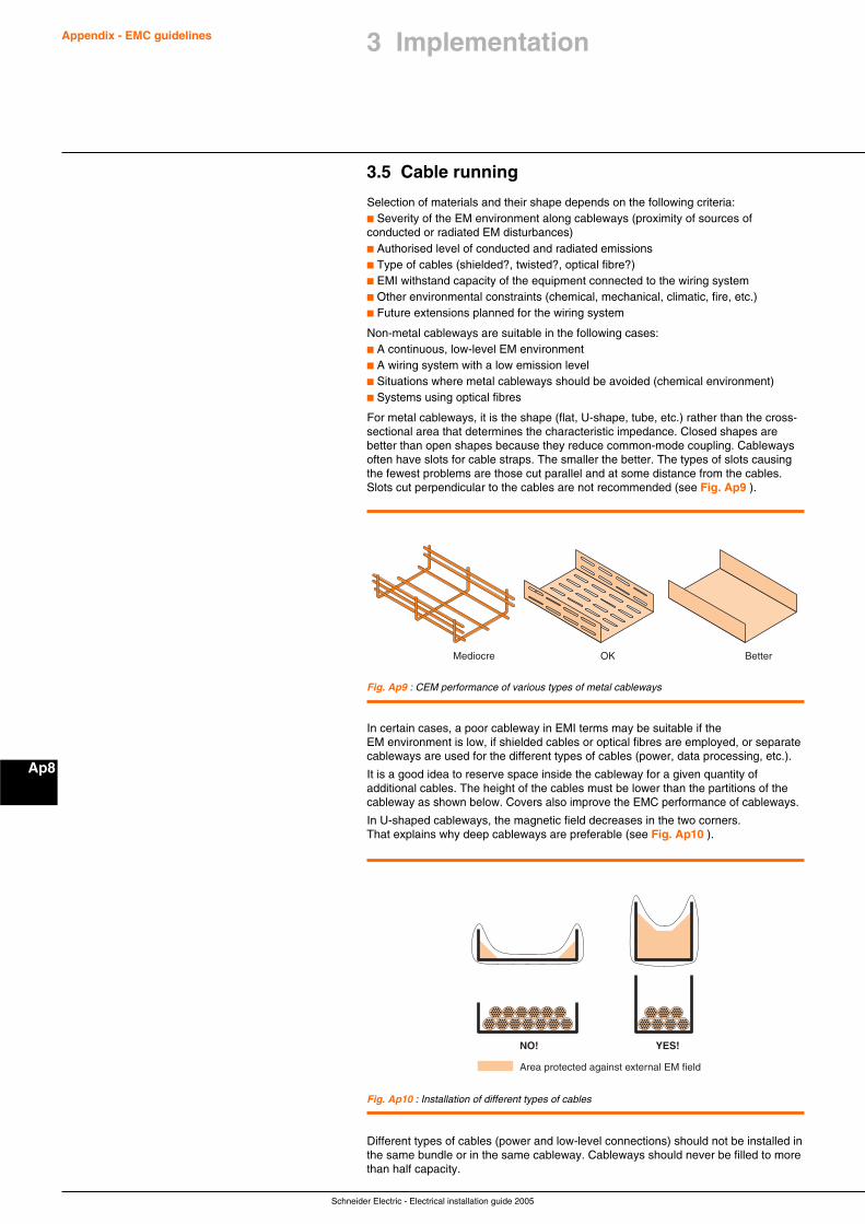
Schneider Electric - Electrical installation guide 2005
Appendix - EMC guidelines
Ap8
Fig. Ap9 : CEM performance of various types of metal cableways
Fig. Ap10 : Installation of different types of cables
Mediocre OK Better
NO!
Area protected against external EM field
YES!
3.5 Cable running
Selection of materials and their shape depends on the following criteria:c Severity of the EM environment along cableways (proximity of sources ofconducted or radiated EM disturbances)c Authorised level of conducted and radiated emissionsc Type of cables (shielded?, twisted?, optical fibre?)c EMI withstand capacity of the equipment connected to the wiring systemc Other environmental constraints (chemical, mechanical, climatic, fire, etc.)c Future extensions planned for the wiring system
Non-metal cableways are suitable in the following cases:c A continuous, low-level EM environmentc A wiring system with a low emission levelc Situations where metal cableways should be avoided (chemical environment)c Systems using optical fibres
For metal cableways, it is the shape (flat, U-shape, tube, etc.) rather than the cross-sectional area that determines the characteristic impedance. Closed shapes arebetter than open shapes because they reduce common-mode coupling. Cablewaysoften have slots for cable straps. The smaller the better. The types of slots causingthe fewest problems are those cut parallel and at some distance from the cables.Slots cut perpendicular to the cables are not recommended (see Fig. Ap9 ).
In certain cases, a poor cableway in EMI terms may be suitable if theEM environment is low, if shielded cables or optical fibres are employed, or separatecableways are used for the different types of cables (power, data processing, etc.).
It is a good idea to reserve space inside the cableway for a given quantity ofadditional cables. The height of the cables must be lower than the partitions of thecableway as shown below. Covers also improve the EMC performance of cableways.
In U-shaped cableways, the magnetic field decreases in the two corners.That explains why deep cableways are preferable (see Fig. Ap10 ).
Different types of cables (power and low-level connections) should not be installed inthe same bundle or in the same cableway. Cableways should never be filled to morethan half capacity.
3 Implementation
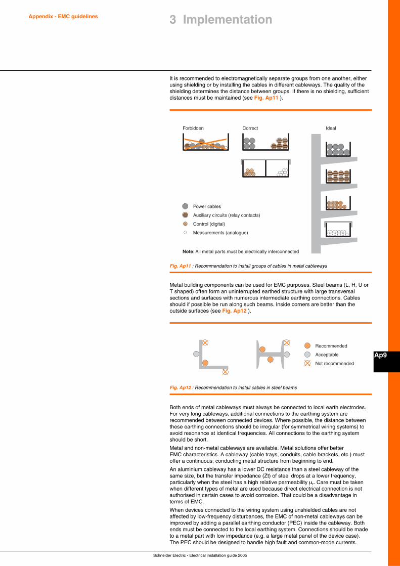
Schneider Electric - Electrical installation guide 2005
Appendix - EMC guidelines
Ap9
3 Implementation
Forbidden Correct Ideal
Power cables
Auxiliary circuits (relay contacts)
Control (digital)
Measurements (analogue)
Note: All metal parts must be electrically interconnected
Fig. Ap11 : Recommendation to install groups of cables in metal cableways
Recommended
Acceptable
Not recommended
Fig. Ap12 : Recommendation to install cables in steel beams
It is recommended to electromagnetically separate groups from one another, eitherusing shielding or by installing the cables in different cableways. The quality of theshielding determines the distance between groups. If there is no shielding, sufficientdistances must be maintained (see Fig. Ap11 ).
Metal building components can be used for EMC purposes. Steel beams (L, H, U orT shaped) often form an uninterrupted earthed structure with large transversalsections and surfaces with numerous intermediate earthing connections. Cablesshould if possible be run along such beams. Inside corners are better than theoutside surfaces (see Fig. Ap12 ).
Both ends of metal cableways must always be connected to local earth electrodes.For very long cableways, additional connections to the earthing system arerecommended between connected devices. Where possible, the distance betweenthese earthing connections should be irregular (for symmetrical wiring systems) toavoid resonance at identical frequencies. All connections to the earthing systemshould be short.
Metal and non-metal cableways are available. Metal solutions offer betterEMC characteristics. A cableway (cable trays, conduits, cable brackets, etc.) mustoffer a continuous, conducting metal structure from beginning to end.
An aluminium cableway has a lower DC resistance than a steel cableway of thesame size, but the transfer impedance (Zt) of steel drops at a lower frequency,particularly when the steel has a high relative permeability µr. Care must be takenwhen different types of metal are used because direct electrical connection is notauthorised in certain cases to avoid corrosion. That could be a disadvantage interms of EMC.
When devices connected to the wiring system using unshielded cables are notaffected by low-frequency disturbances, the EMC of non-metal cableways can beimproved by adding a parallel earthing conductor (PEC) inside the cableway. Bothends must be connected to the local earthing system. Connections should be madeto a metal part with low impedance (e.g. a large metal panel of the device case).The PEC should be designed to handle high fault and common-mode currents.
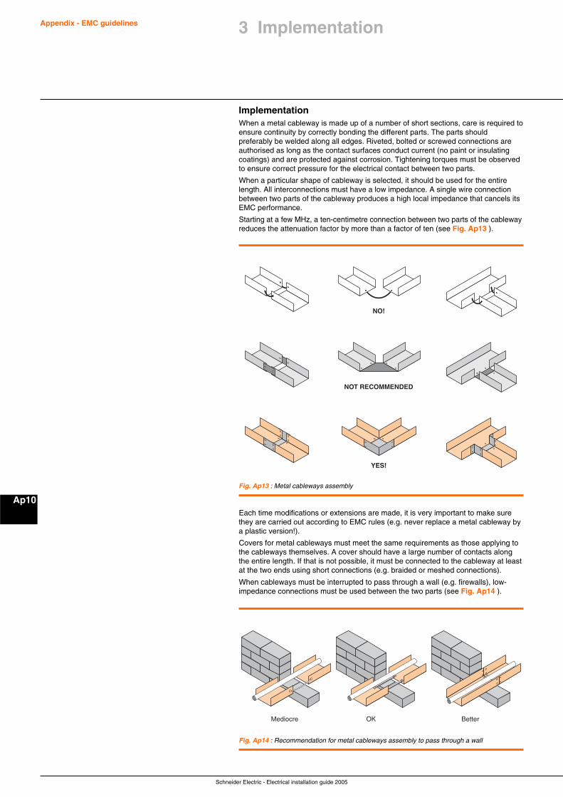
Schneider Electric - Electrical installation guide 2005
Appendix - EMC guidelines
Ap10
Fig. Ap13 : Metal cableways assembly
NO!
NOT RECOMMENDED
YES!
Mediocre OK Better
Fig. Ap14 : Recommendation for metal cableways assembly to pass through a wall
ImplementationWhen a metal cableway is made up of a number of short sections, care is required toensure continuity by correctly bonding the different parts. The parts shouldpreferably be welded along all edges. Riveted, bolted or screwed connections areauthorised as long as the contact surfaces conduct current (no paint or insulatingcoatings) and are protected against corrosion. Tightening torques must be observedto ensure correct pressure for the electrical contact between two parts.
When a particular shape of cableway is selected, it should be used for the entirelength. All interconnections must have a low impedance. A single wire connectionbetween two parts of the cableway produces a high local impedance that cancels itsEMC performance.
Starting at a few MHz, a ten-centimetre connection between two parts of the cablewayreduces the attenuation factor by more than a factor of ten (see Fig. Ap13 ).
Each time modifications or extensions are made, it is very important to make surethey are carried out according to EMC rules (e.g. never replace a metal cableway bya plastic version!).
Covers for metal cableways must meet the same requirements as those applying tothe cableways themselves. A cover should have a large number of contacts alongthe entire length. If that is not possible, it must be connected to the cableway at leastat the two ends using short connections (e.g. braided or meshed connections).
When cableways must be interrupted to pass through a wall (e.g. firewalls), low-impedance connections must be used between the two parts (see Fig. Ap14 ).
3 Implementation
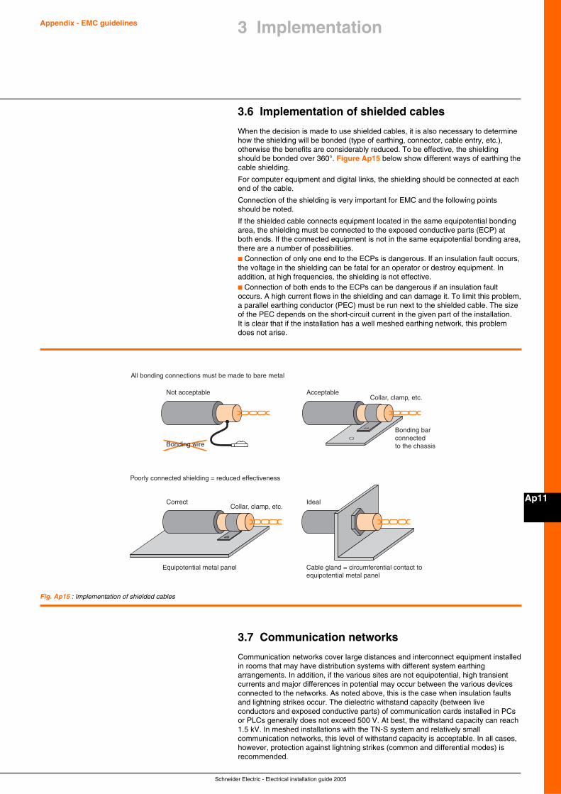
Schneider Electric - Electrical installation guide 2005
Appendix - EMC guidelines
Ap11
3 Implementation
3.6 Implementation of shielded cables
When the decision is made to use shielded cables, it is also necessary to determinehow the shielding will be bonded (type of earthing, connector, cable entry, etc.),otherwise the benefits are considerably reduced. To be effective, the shieldingshould be bonded over 360°. Figure Ap15 below show different ways of earthing thecable shielding.
For computer equipment and digital links, the shielding should be connected at eachend of the cable.
Connection of the shielding is very important for EMC and the following pointsshould be noted.
If the shielded cable connects equipment located in the same equipotential bondingarea, the shielding must be connected to the exposed conductive parts (ECP) atboth ends. If the connected equipment is not in the same equipotential bonding area,there are a number of possibilities.c Connection of only one end to the ECPs is dangerous. If an insulation fault occurs,the voltage in the shielding can be fatal for an operator or destroy equipment. Inaddition, at high frequencies, the shielding is not effective.c Connection of both ends to the ECPs can be dangerous if an insulation faultoccurs. A high current flows in the shielding and can damage it. To limit this problem,a parallel earthing conductor (PEC) must be run next to the shielded cable. The sizeof the PEC depends on the short-circuit current in the given part of the installation.It is clear that if the installation has a well meshed earthing network, this problemdoes not arise.
Not acceptable
Bonding bar connectedto the chassis
Equipotential metal panel
Poorly connected shielding = reduced effectiveness
Collar, clamp, etc.
Collar, clamp, etc.
Cable gland = circumferential contact toequipotential metal panel
Acceptable
Correct
All bonding connections must be made to bare metal
Ideal
Bonding wire
Fig. Ap15 : Implementation of shielded cables
3.7 Communication networks
Communication networks cover large distances and interconnect equipment installedin rooms that may have distribution systems with different system earthingarrangements. In addition, if the various sites are not equipotential, high transientcurrents and major differences in potential may occur between the various devicesconnected to the networks. As noted above, this is the case when insulation faultsand lightning strikes occur. The dielectric withstand capacity (between liveconductors and exposed conductive parts) of communication cards installed in PCsor PLCs generally does not exceed 500 V. At best, the withstand capacity can reach1.5 kV. In meshed installations with the TN-S system and relatively smallcommunication networks, this level of withstand capacity is acceptable. In all cases,however, protection against lightning strikes (common and differential modes) isrecommended.
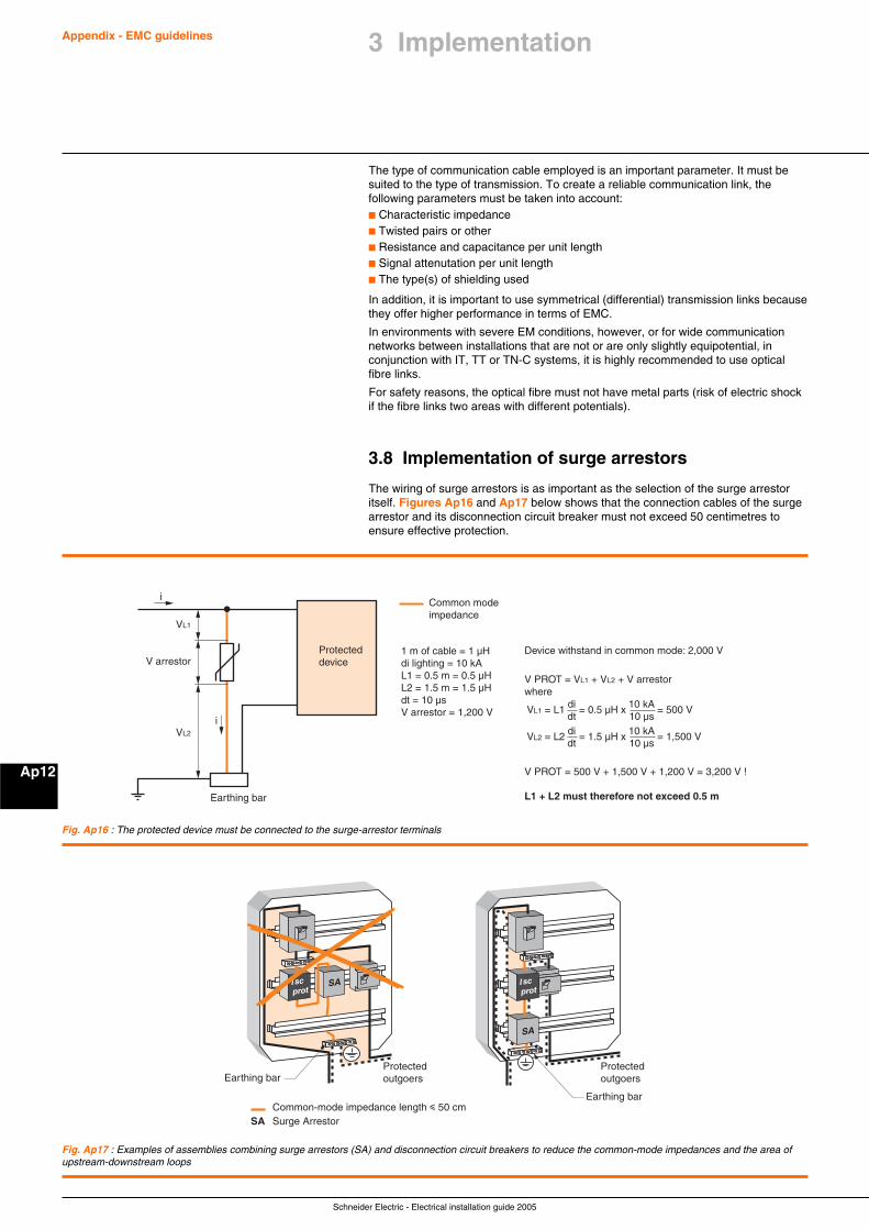
Schneider Electric - Electrical installation guide 2005
Appendix - EMC guidelines
Ap12
The type of communication cable employed is an important parameter. It must besuited to the type of transmission. To create a reliable communication link, thefollowing parameters must be taken into account:c Characteristic impedancec Twisted pairs or otherc Resistance and capacitance per unit lengthc Signal attenutation per unit lengthc The type(s) of shielding used
In addition, it is important to use symmetrical (differential) transmission links becausethey offer higher performance in terms of EMC.
In environments with severe EM conditions, however, or for wide communicationnetworks between installations that are not or are only slightly equipotential, inconjunction with IT, TT or TN-C systems, it is highly recommended to use opticalfibre links.
For safety reasons, the optical fibre must not have metal parts (risk of electric shockif the fibre links two areas with different potentials).
3.8 Implementation of surge arrestors
The wiring of surge arrestors is as important as the selection of the surge arrestoritself. Figures Ap16 and Ap17 below shows that the connection cables of the surgearrestor and its disconnection circuit breaker must not exceed 50 centimetres toensure effective protection.
ProtecteddeviceV arrestor
Common mode impedance
Earthing bar
1 m of cable = 1 µHdi lighting = 10 kAL1 = 0.5 m = 0.5 µHL2 = 1.5 m = 1.5 µHdt = 10 µsV arrestor = 1,200 V
Device withstand in common mode: 2,000 V
V PROT = VL1 + VL2 + V arrestorwhere
V PROT = 500 V + 1,500 V + 1,200 V = 3,200 V !
L1 + L2 must therefore not exceed 0.5 m
i
i
VL1
VL2
10 kA10 µs
didt
VL1 = L1 = 0.5 µH x = 500 V
10 kA10 µs
didt
VL2 = L2 = 1.5 µH x = 1,500 V
Fig. Ap16 : The protected device must be connected to the surge-arrestor terminals
Fig. Ap17 : Examples of assemblies combining surge arrestors (SA) and disconnection circuit breakers to reduce the common-mode impedances and the area ofupstream-downstream loops
ProtectedoutgoersEarthing bar
Common-mode impedance length i 50 cmSurge ArrestorSA
Earthing bar
Protectedoutgoers
Iscprot
Iscprot
SA
SA
3 Implementation
Schneider Electric - Electrical installation guide 2005
Appendix - EMC guidelines
Ap13
3 Implementation
3.9 Standards
It is absolutely indispensable to specify the standards and recommendations thatmust be taken into account for installations.
Below are several documents that may be used:
c EN 50174-1 Information technology - Cabling installation. Part 1: Specificationand quality assurance
c EN 50174-2 Information technology - Cabling installation. Part 2: Installationplanning and practices inside buildings

Schneider Electric - Electrical installation guide 2005
Appendix - EMC guidelines
Ap14
4 Coupling mechanisms andcounter-measures
4.1 General
An EM interference phenomenon may be summed up in Figure Ap18 below.
Walkie-talkie TV set
Radiated waves
CouplingSource Victim
Means by whichdisturbances aretransmitted
Origin ofemitted disturbances
Example:
Equipment likelyto be disturbed
Fig. Ap18 : EM interference phenomenon
The different sources of disturbances are:c Radio-frequency emissionsv Wireless communication systems (radio, TV, CB, radio telephones, remote controls)v Radarc Electrical equipmentv High-power industrial equipment (induction furnaces, welding machines, statorcontrol systems)v Office equipment (computers and electronic circuits, photocopy machines, largemonitors)v Discharge lamps (neon, fluorescent, flash, etc.)v Electromechanical components (relays, contactors, solenoids, current interruptiondevices)c Power systemsv Power transmission and distribution systemsv Electrical transportation systemsc Lightningc Electrostatic discharges (ESD)c Electromagnetic nuclear pulses (EMNP)
The potential victims are:c Radio and television receivers, radar, wireless communication systemsc Analogue systems (sensors, measurement acquisition, amplifiers, monitors)c Digital systems (computers, computer communications, peripheral equipment)
The different types of coupling are:c Common-mode impedance (galvanic) couplingc Capacitive couplingc Inductive couplingc Radiated coupling (cable to cable, field to cable, antenna to antenna)
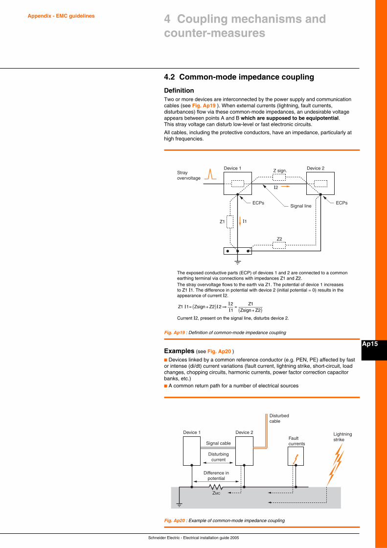
Schneider Electric - Electrical installation guide 2005
Appendix - EMC guidelines
Ap15
4.2 Common-mode impedance coupling
DefinitionTwo or more devices are interconnected by the power supply and communicationcables (see Fig. Ap19 ). When external currents (lightning, fault currents,disturbances) flow via these common-mode impedances, an undesirable voltageappears between points A and B which are supposed to be equipotential.This stray voltage can disturb low-level or fast electronic circuits.
All cables, including the protective conductors, have an impedance, particularly athigh frequencies.
Fig. Ap19 : Definition of common-mode impedance coupling
Examples (see Fig. Ap20 )
c Devices linked by a common reference conductor (e.g. PEN, PE) affected by fastor intense (di/dt) current variations (fault current, lightning strike, short-circuit, loadchanges, chopping circuits, harmonic currents, power factor correction capacitorbanks, etc.)c A common return path for a number of electrical sources
Strayovervoltage
Device 1
Z2
Z1
Z sign.
I2
I1
Device 2
Signal lineECPs ECPs
The exposed conductive parts (ECP) of devices 1 and 2 are connected to a commonearthing terminal via connections with impedances Z1 and Z2.The stray overvoltage flows to the earth via Z1. The potential of device 1 increasesto Z1 I1. The difference in potential with device 2 (initial potential = 0) results in theappearance of current I2.
Z Zsign ZZ
Zsign Z1 1 2 2
21
12
I III
= +( ) ⇒ =+( )
Current I2, present on the signal line, disturbs device 2.
Device 1 Device 2
Signal cable
Disturbedcable
Faultcurrents
Lightningstrike
Disturbingcurrent
Difference inpotential
ZMC
Fig. Ap20 : Example of common-mode impedance coupling
4 Coupling mechanisms andcounter-measures
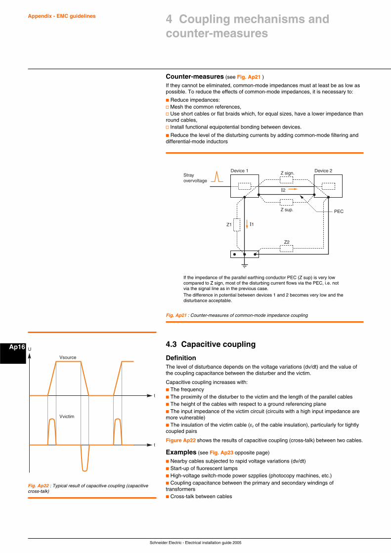
Schneider Electric - Electrical installation guide 2005
Appendix - EMC guidelines
Ap16
Counter-measures (see Fig. Ap21 )
If they cannot be eliminated, common-mode impedances must at least be as low aspossible. To reduce the effects of common-mode impedances, it is necessary to:
c Reduce impedances:v Mesh the common references,v Use short cables or flat braids which, for equal sizes, have a lower impedance thanround cables,v Install functional equipotential bonding between devices.
c Reduce the level of the disturbing currents by adding common-mode filtering anddifferential-mode inductors
If the impedance of the parallel earthing conductor PEC (Z sup) is very lowcompared to Z sign, most of the disturbing current flows via the PEC, i.e. notvia the signal line as in the previous case.The difference in potential between devices 1 and 2 becomes very low and thedisturbance acceptable.
Strayovervoltage
Device 1
Z2
Z1
Z sign.
Z sup.
I2
I1
Device 2
PEC
Fig. Ap21 : Counter-measures of common-mode impedance coupling
4.3 Capacitive coupling
DefinitionThe level of disturbance depends on the voltage variations (dv/dt) and the value ofthe coupling capacitance between the disturber and the victim.
Capacitive coupling increases with:c The frequencyc The proximity of the disturber to the victim and the length of the parallel cablesc The height of the cables with respect to a ground referencing planec The input impedance of the victim circuit (circuits with a high input impedance aremore vulnerable)c The insulation of the victim cable (εr of the cable insulation), particularly for tightlycoupled pairs
Figure Ap22 shows the results of capacitive coupling (cross-talk) between two cables.
Examples (see Fig. Ap23 opposite page)
c Nearby cables subjected to rapid voltage variations (dv/dt)c Start-up of fluorescent lampsc High-voltage switch-mode power szpplies (photocopy machines, etc.)c Coupling capacitance between the primary and secondary windings oftransformersc Cross-talk between cables
Fig. Ap22 : Typical result of capacitive coupling (capacitivecross-talk)
t
t
U
Vsource
Vvictim
4 Coupling mechanisms andcounter-measures
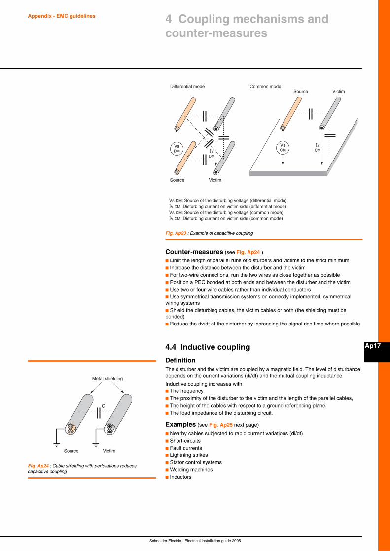
Schneider Electric - Electrical installation guide 2005
Appendix - EMC guidelines
Ap17
Counter-measures (see Fig. Ap24 )
c Limit the length of parallel runs of disturbers and victims to the strict minimumc Increase the distance between the disturber and the victimc For two-wire connections, run the two wires as close together as possiblec Position a PEC bonded at both ends and between the disturber and the victimc Use two or four-wire cables rather than individual conductorsc Use symmetrical transmission systems on correctly implemented, symmetricalwiring systemsc Shield the disturbing cables, the victim cables or both (the shielding must bebonded)c Reduce the dv/dt of the disturber by increasing the signal rise time where possible
4.4 Inductive coupling
DefinitionThe disturber and the victim are coupled by a magnetic field. The level of disturbancedepends on the current variations (di/dt) and the mutual coupling inductance.
Inductive coupling increases with:c The frequencyc The proximity of the disturber to the victim and the length of the parallel cables,c The height of the cables with respect to a ground referencing plane,c The load impedance of the disturbing circuit.
Examples (see Fig. Ap25 next page)
c Nearby cables subjected to rapid current variations (di/dt)c Short-circuitsc Fault currentsc Lightning strikesc Stator control systemsc Welding machinesc Inductors
Source
Differential mode Common mode
Victim
Source Victim
VsDM
Vs DM: Source of the disturbing voltage (differential mode)Iv DM: Disturbing current on victim side (differential mode)Vs CM: Source of the disturbing voltage (common mode)Iv CM: Disturbing current on victim side (common mode)
IvDM
VsCM
IvCM
Fig. Ap23 : Example of capacitive coupling
Fig. Ap24 : Cable shielding with perforations reducescapacitive coupling
Metal shielding
Source
C
Victim
4 Coupling mechanisms andcounter-measures
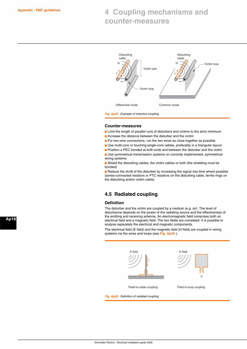
Schneider Electric - Electrical installation guide 2005
Appendix - EMC guidelines
Ap18
Counter-measuresc Limit the length of parallel runs of disturbers and victims to the strict minimumc Increase the distance between the disturber and the victimc For two-wire connections, run the two wires as close together as possiblec Use multi-core or touching single-core cables, preferably in a triangular layoutc Position a PEC bonded at both ends and between the disturber and the victimc Use symmetrical transmission systems on correctly implemented, symmetricalwiring systemsc Shield the disturbing cables, the victim cables or both (the shielding must bebonded)c Reduce the dv/dt of the disturber by increasing the signal rise time where possible(series-connected resistors or PTC resistors on the disturbing cable, ferrite rings onthe disturbing and/or victim cable)
4.5 Radiated coupling
DefinitionThe disturber and the victim are coupled by a medium (e.g. air). The level ofdisturbance depends on the power of the radiating source and the effectiveness ofthe emitting and receiving antenna. An electromagnetic field comprises both anelectrical field and a magnetic field. The two fields are correlated. It is possible toanalyse separately the electrical and magnetic components.
The electrical field (E field) and the magnetic field (H field) are coupled in wiringsystems via the wires and loops (see Fig. Ap26 ).
H
Victim loop
Victim pair
i
Differential mode Common mode
H
Disturbingcable
Disturbingcable
Victim loop
i
Fig. Ap25 : Example of inductive coupling
E field
i
Field-to-cable coupling Field-to-loop coupling
H field
V
Fig. Ap26 : Definition of radiated coupling
4 Coupling mechanisms andcounter-measures
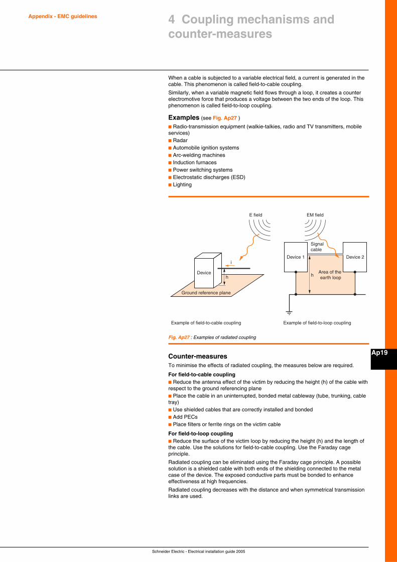
Schneider Electric - Electrical installation guide 2005
Appendix - EMC guidelines
Ap19
4 Coupling mechanisms andcounter-measures
When a cable is subjected to a variable electrical field, a current is generated in thecable. This phenomenon is called field-to-cable coupling.
Similarly, when a variable magnetic field flows through a loop, it creates a counterelectromotive force that produces a voltage between the two ends of the loop. Thisphenomenon is called field-to-loop coupling.
Examples (see Fig. Ap27 )
c Radio-transmission equipment (walkie-talkies, radio and TV transmitters, mobileservices)c Radarc Automobile ignition systemsc Arc-welding machinesc Induction furnacesc Power switching systemsc Electrostatic discharges (ESD)c Lighting
EM field
i
Example of field-to-cable coupling Example of field-to-loop coupling
Device 1 Device 2
Signal cable
hArea of the earth looph
E field
Device
Ground reference plane
Fig. Ap27 : Examples of radiated coupling
Counter-measuresTo minimise the effects of radiated coupling, the measures below are required.
For field-to-cable couplingc Reduce the antenna effect of the victim by reducing the height (h) of the cable withrespect to the ground referencing planec Place the cable in an uninterrupted, bonded metal cableway (tube, trunking, cabletray)c Use shielded cables that are correctly installed and bondedc Add PECsc Place filters or ferrite rings on the victim cable
For field-to-loop couplingc Reduce the surface of the victim loop by reducing the height (h) and the length ofthe cable. Use the solutions for field-to-cable coupling. Use the Faraday cageprinciple.
Radiated coupling can be eliminated using the Faraday cage principle. A possiblesolution is a shielded cable with both ends of the shielding connected to the metalcase of the device. The exposed conductive parts must be bonded to enhanceeffectiveness at high frequencies.
Radiated coupling decreases with the distance and when symmetrical transmissionlinks are used.
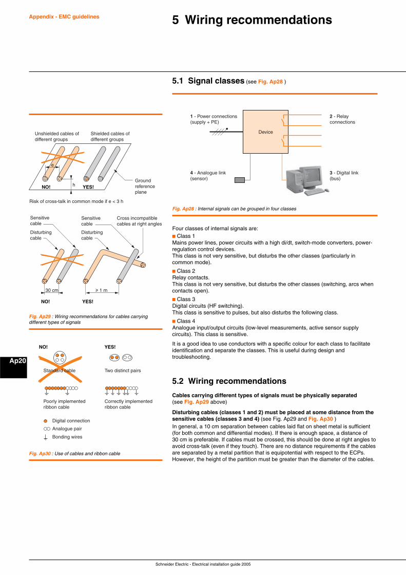
Schneider Electric - Electrical installation guide 2005
Appendix - EMC guidelines
Ap20
5 Wiring recommendations
5.1 Signal classes (see Fig. Ap28 )
Device
1 - Power connections(supply + PE)
2 - Relay connections
4 - Analogue link(sensor)
3 - Digital link(bus)
Fig. Ap28 : Internal signals can be grouped in four classes
Four classes of internal signals are:c Class 1Mains power lines, power circuits with a high di/dt, switch-mode converters, power-regulation control devices.This class is not very sensitive, but disturbs the other classes (particularly incommon mode).
c Class 2Relay contacts.This class is not very sensitive, but disturbs the other classes (switching, arcs whencontacts open).
c Class 3Digital circuits (HF switching).This class is sensitive to pulses, but also disturbs the following class.
c Class 4Analogue input/output circuits (low-level measurements, active sensor supplycircuits). This class is sensitive.
It is a good idea to use conductors with a specific colour for each class to facilitateidentification and separate the classes. This is useful during design andtroubleshooting.
5.2 Wiring recommendations
Cables carrying different types of signals must be physically separated(see Fig. Ap29 above)
Disturbing cables (classes 1 and 2) must be placed at some distance from thesensitive cables (classes 3 and 4) (see Fig. Ap29 and Fig. Ap30 )In general, a 10 cm separation between cables laid flat on sheet metal is sufficient(for both common and differential modes). If there is enough space, a distance of30 cm is preferable. If cables must be crossed, this should be done at right angles toavoid cross-talk (even if they touch). There are no distance requirements if the cablesare separated by a metal partition that is equipotential with respect to the ECPs.However, the height of the partition must be greater than the diameter of the cables.
NO! YES!
Unshielded cables of different groups
Risk of cross-talk in common mode if e < 3 h
Disturbingcable
Sensitivecable
Shielded cables of different groups
Ground reference plane
h
e
NO! YES!
Cross incompatible cables at right angles
Disturbingcable
Sensitivecable
30 cm u 1 m
Fig. Ap29 : Wiring recommendations for cables carryingdifferent types of signals
Digital connection
Two distinct pairs
Poorly implementedribbon cable
Correctly implementedribbon cable
Bonding wires
Analogue pair
NO! YES!
Standard cable
Fig. Ap30 : Use of cables and ribbon cable
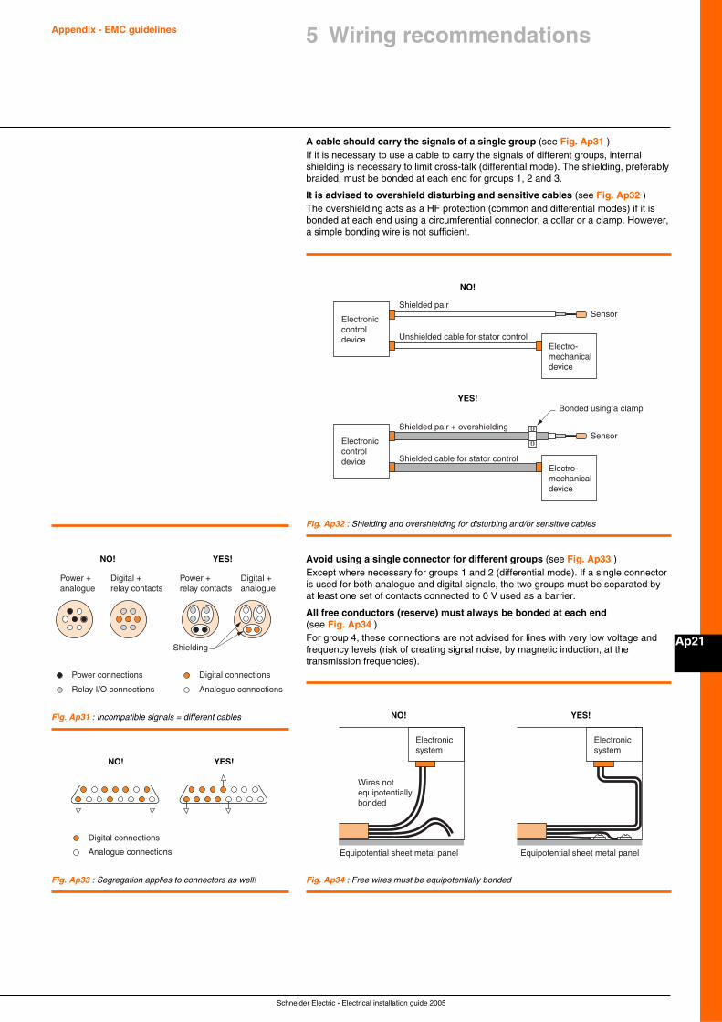
Schneider Electric - Electrical installation guide 2005
Appendix - EMC guidelines
Ap21
A cable should carry the signals of a single group (see Fig. Ap31 )If it is necessary to use a cable to carry the signals of different groups, internalshielding is necessary to limit cross-talk (differential mode). The shielding, preferablybraided, must be bonded at each end for groups 1, 2 and 3.
It is advised to overshield disturbing and sensitive cables (see Fig. Ap32 )The overshielding acts as a HF protection (common and differential modes) if it isbonded at each end using a circumferential connector, a collar or a clamp. However,a simple bonding wire is not sufficient.
Digital connections
Analogue connections
Power connections
Shielding
Power + analogue
Power + relay contacts
Digital + relay contacts
Digital + analogue
Relay I/O connections
NO! YES!
Fig. Ap31 : Incompatible signals = different cables
Electroniccontroldevice
NO!
Electro-mechanicaldevice
Shielded pairSensor
Unshielded cable for stator control
Electroniccontroldevice
YES!
Electro-mechanicaldevice
Shielded pair + overshielding
Bonded using a clamp
Sensor
Shielded cable for stator control
Fig. Ap32 : Shielding and overshielding for disturbing and/or sensitive cables
Avoid using a single connector for different groups (see Fig. Ap33 )Except where necessary for groups 1 and 2 (differential mode). If a single connectoris used for both analogue and digital signals, the two groups must be separated byat least one set of contacts connected to 0 V used as a barrier.
All free conductors (reserve) must always be bonded at each end(see Fig. Ap34 )For group 4, these connections are not advised for lines with very low voltage andfrequency levels (risk of creating signal noise, by magnetic induction, at thetransmission frequencies).
Digital connections
Analogue connections
NO! YES!
Fig. Ap33 : Segregation applies to connectors as well!
NO! YES!
Electronicsystem
Equipotential sheet metal panel
Wires not equipotentially bonded
Equipotential sheet metal panel
Electronicsystem
Fig. Ap34 : Free wires must be equipotentially bonded
5 Wiring recommendations
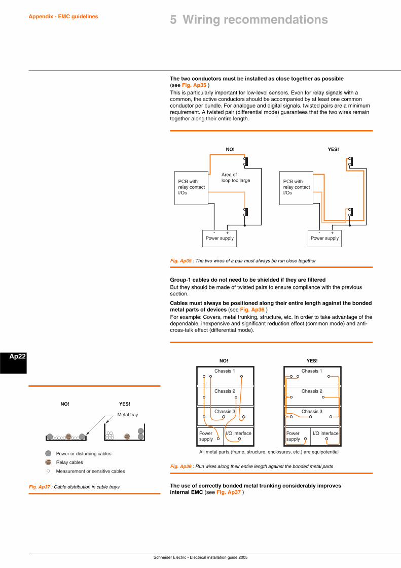
Schneider Electric - Electrical installation guide 2005
Appendix - EMC guidelines
Ap22
5 Wiring recommendations
The two conductors must be installed as close together as possible(see Fig. Ap35 )This is particularly important for low-level sensors. Even for relay signals with acommon, the active conductors should be accompanied by at least one commonconductor per bundle. For analogue and digital signals, twisted pairs are a minimumrequirement. A twisted pair (differential mode) guarantees that the two wires remaintogether along their entire length.
NO! YES!
PCB withrelay contactI/Os
Power supply
Area ofloop too large
- +
PCB withrelay contactI/Os
Power supply- +
Fig. Ap35 : The two wires of a pair must always be run close together
Group-1 cables do not need to be shielded if they are filteredBut they should be made of twisted pairs to ensure compliance with the previoussection.
Cables must always be positioned along their entire length against the bondedmetal parts of devices (see Fig. Ap36 )For example: Covers, metal trunking, structure, etc. In order to take advantage of thedependable, inexpensive and significant reduction effect (common mode) and anti-cross-talk effect (differential mode).
NO! YES!
Chassis 1
All metal parts (frame, structure, enclosures, etc.) are equipotential
Chassis 2
Chassis 3
Powersupply
I/O interface
Chassis 1
Chassis 2
Chassis 3
Powersupply
I/O interface
Fig. Ap36 : Run wires along their entire length against the bonded metal parts
The use of correctly bonded metal trunking considerably improvesinternal EMC (see Fig. Ap37 )
Power or disturbing cables
Relay cables
Measurement or sensitive cables
Metal tray
NO! YES!
Fig. Ap37 : Cable distribution in cable trays