ELECTRICAL - IMU-MPC LIBRARYELECTRICAL TECHNOLOGY B.L THERAJA A.K THERAJA 4 –2 2016 vt. Ltd. ....
24
4 – 1 Copyright © 2016 by S. Chand & Company Pvt. Ltd. All rights reserved. Copyright © 2016 by S. Chand & Company Pvt. Ltd. All rights reserved. A TEXTBOOK OF ELECTRICAL TECHNOLOGY B.L THERAJA A.K THERAJA
Transcript of ELECTRICAL - IMU-MPC LIBRARYELECTRICAL TECHNOLOGY B.L THERAJA A.K THERAJA 4 –2 2016 vt. Ltd. ....

4 – 1
Cop
yrigh
t © 2016 b
y S. C
han
d &
Com
pan
y P
vt. Ltd
. All righ
ts reserved.
Cop
yrigh
t © 2016 b
y S. C
han
d &
Com
pan
y P
vt. Ltd
. All righ
ts reserved.
A TEXTBOOK OF
ELECTRICALTECHNOLOGY
B.L THERAJA
A.K THERAJA
4 – 2
Cop
yrigh
t © 2016 b
y S. C
han
d &
Com
pan
y P
vt. Ltd
. All righ
ts reserved.
Electrostatics

4 – 3
Cop
yrigh
t © 2016 b
y S. C
han
d &
Com
pan
y P
vt. Ltd
. All righ
ts reserved.
Electrostatics
Static Electricity
Absolute and Relative Permittivity of a Medium
Laws of Electrostatics
Electric Field
Electrostatic Induction
Electric Flux and Faraday Tubes
Field Strength or Field Intensity or Electric Intensity (E)
Electric Flux Density or Electric Displacement D
Gauss Law
The Equations of Poisson and Laplace
Electric Potential and Energy
Potential and Potential Difference
C-4
Contd….

4 – 4
Cop
yrigh
t © 2016 b
y S. C
han
d &
Com
pan
y P
vt. Ltd
. All righ
ts reserved.
Electrostatics
Potential at a Point
Potential of a Charged Sphere
Equipotential Surfaces
Potential and Electric Intensity Inside a Conducting Sphere
Potential Gradient
Breakdown Voltage and Dielectric Strength
Safety Factor of Dielectric
Boundary Conditions
C-4

4 – 5
Cop
yrigh
t © 2016 b
y S. C
han
d &
Com
pan
y P
vt. Ltd
. All righ
ts reserved.
In the preceding chapters, we concerned ourselves exclusively
with electric current i.e. electricity in motion. Now, we will discuss
the behaviour of static electricity and the laws governing it.
In fact, electrostatics is that branch of science which deals with
the phenomena associated with electricity at rest.
In brief, we can say that positive electrification of a body results
from a deficiency of the electrons whereas negative electrification
results from an excess of electrons.
Static Electricity

4 – 6
Cop
yrigh
t © 2016 b
y S. C
han
d &
Com
pan
y P
vt. Ltd
. All righ
ts reserved.
While discussing electrostatic phenomenon, a certain property of the
medium called its permittivity plays an important role. Every medium
is supposed to possess two permittivities :
Absolute permittivity (ε) and
Relative permittivity (εr).
Absolute and Relative Permittivity of a Medium

4 – 7
Cop
yrigh
t © 2016 b
y S. C
han
d &
Com
pan
y P
vt. Ltd
. All righ
ts reserved.
First Law. Like charges of electricity repel each other, whereas
unlike charges attract each other.
Second Law. According to this law, the force exerted between two
point charges (i) is directly proportional to the product of their
strengths (ii) is inversely proportional to the square of the
distance between them.
Laws of Electrostatics
4 – 8
Cop
yrigh
t © 2016 b
y S. C
han
d &
Com
pan
y P
vt. Ltd
. All righ
ts reserved.
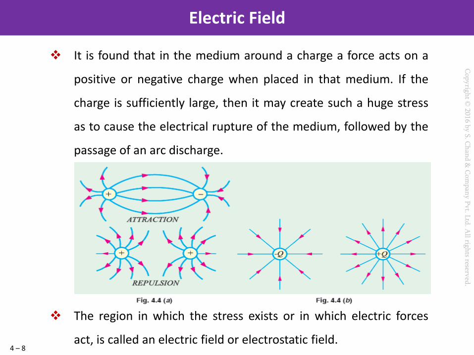
It is found that in the medium around a charge a force acts on a
positive or negative charge when placed in that medium. If the
charge is sufficiently large, then it may create such a huge stress
as to cause the electrical rupture of the medium, followed by the
passage of an arc discharge.
The region in which the stress exists or in which electric forces
act, is called an electric field or electrostatic field.
Electric Field
4 – 9
Cop
yrigh
t © 2016 b
y S. C
han
d &
Com
pan
y P
vt. Ltd
. All righ
ts reserved.
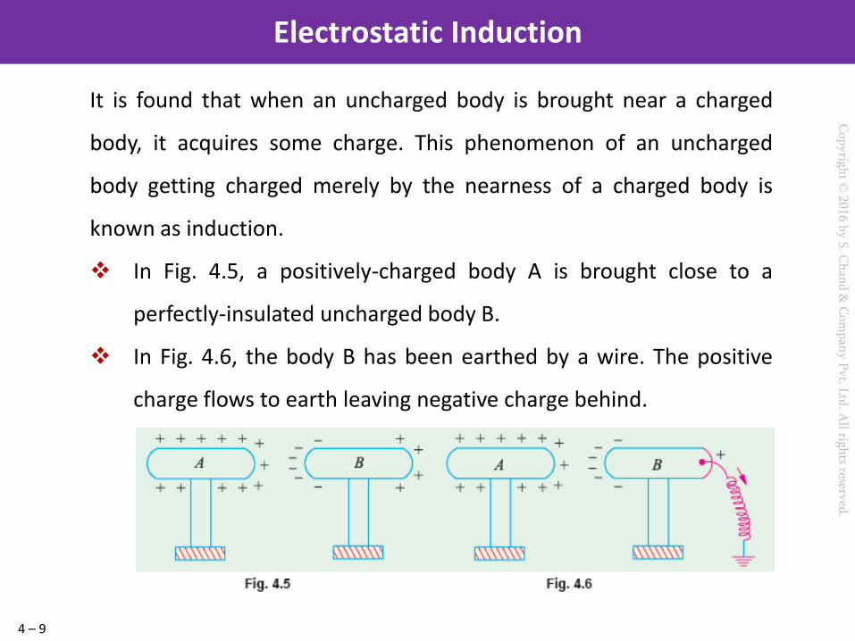
It is found that when an uncharged body is brought near a charged
body, it acquires some charge. This phenomenon of an uncharged
body getting charged merely by the nearness of a charged body is
known as induction.
In Fig. 4.5, a positively-charged body A is brought close to a
perfectly-insulated uncharged body B.
In Fig. 4.6, the body B has been earthed by a wire. The positive
charge flows to earth leaving negative charge behind.
Electrostatic Induction
4 – 10
Cop
yrigh
t © 2016 b
y S. C
han
d &
Com
pan
y P
vt. Ltd
. All righ
ts reserved.
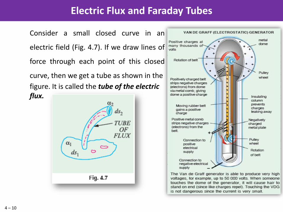
Consider a small closed curve in an
electric field (Fig. 4.7). If we draw lines of
force through each point of this closed
curve, then we get a tube as shown in the
figure. It is called the tube of the electric flux.
Electric Flux and Faraday Tubes

4 – 11
Cop
yrigh
t © 2016 b
y S. C
han
d &
Com
pan
y P
vt. Ltd
. All righ
ts reserved.
Electric intensity at any point within an electric field may be defined in
either of the following three ways :
It is given by the force experienced by a unit positive charge
placed at that point. Its direction is the direction along which the
force acts. Obviously, the unit of E is newton /coulomb (N/C).
Electric intensity at a point may be defined as equal to the lines of
force passing normally through a unit cross-section at that point.
Suppose, there is a charge of Q coulombs. The number of lines of
force produced by it is Q/ε.
Electric intensity at any point in an electric field is equal to the
potential gradient at that point.
Contd….
Field Strength or Field Intensity or Electric Intensity (E)
4 – 12
Cop
yrigh
t © 2016 b
y S. C
han
d &
Com
pan
y P
vt. Ltd
. All righ
ts reserved.
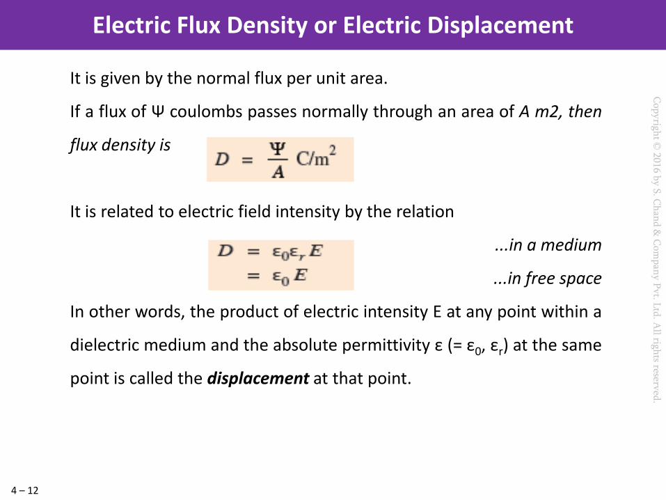
It is given by the normal flux per unit area.
If a flux of Ψ coulombs passes normally through an area of A m2, then
flux density is
It is related to electric field intensity by the relation
...in a medium
...in free space
In other words, the product of electric intensity E at any point within a
dielectric medium and the absolute permittivity ε (= ε0, εr) at the same
point is called the displacement at that point.
Electric Flux Density or Electric Displacement

4 – 13
Cop
yrigh
t © 2016 b
y S. C
han
d &
Com
pan
y P
vt. Ltd
. All righ
ts reserved.
Consider a point charge Q lying at the centre of a sphere of radius r
which surrounds it completely [Fig. 4.11 (a)]. The total number of tubes
of flux originating from the charge is Q (but number of lines of force is
Q/ε0) and are normal to the surface of the sphere. The electric field E
which equals Q/4 π ε0 r2 is also normal to the surface. As said earlier,
total number of lines of force passing perpendicularly through the
whole surface of the sphere is
Gauss* Law
4 – 14
Cop
yrigh
t © 2016 b
y S. C
han
d &
Com
pan
y P
vt. Ltd
. All righ
ts reserved.
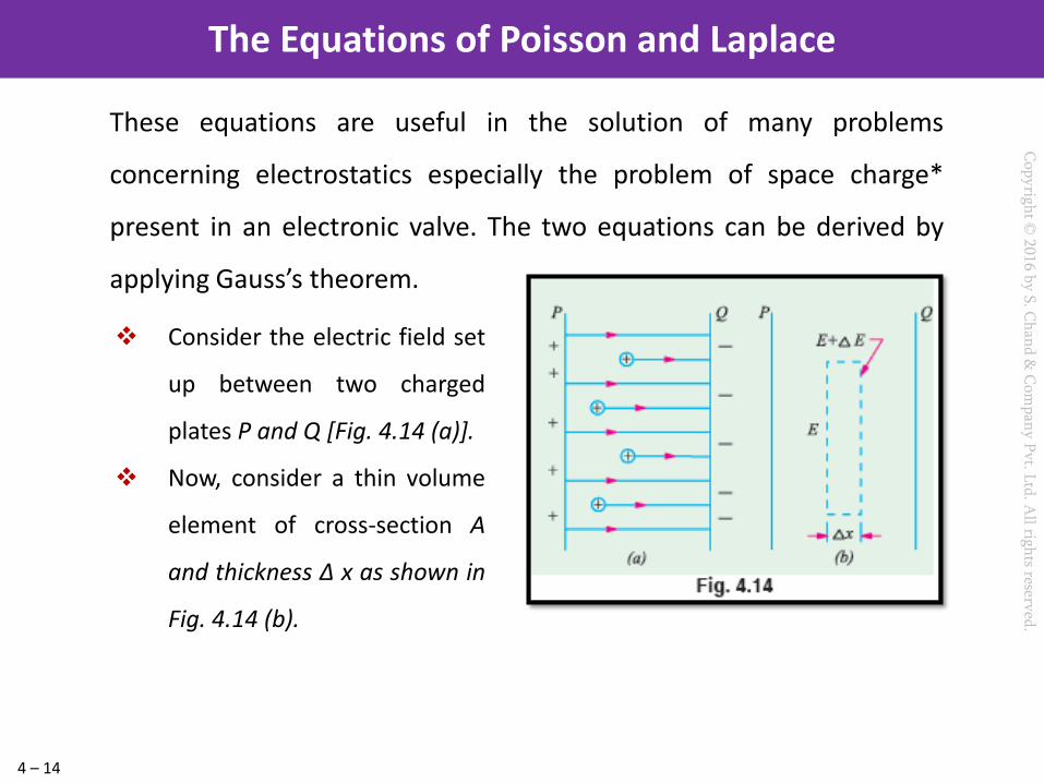
These equations are useful in the solution of many problems
concerning electrostatics especially the problem of space charge*
present in an electronic valve. The two equations can be derived by
applying Gauss’s theorem.
The Equations of Poisson and Laplace
Consider the electric field set
up between two charged
plates P and Q [Fig. 4.14 (a)].
Now, consider a thin volume
element of cross-section A
and thickness Δ x as shown in
Fig. 4.14 (b).
4 – 15
Cop
yrigh
t © 2016 b
y S. C
han
d &
Com
pan
y P
vt. Ltd
. All righ
ts reserved.
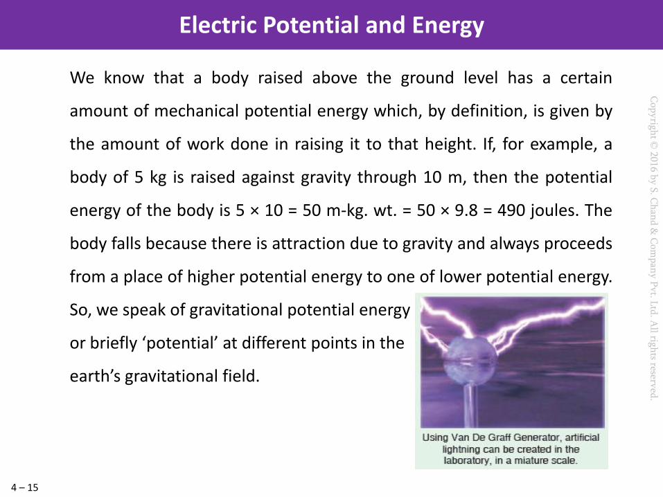
We know that a body raised above the ground level has a certain
amount of mechanical potential energy which, by definition, is given by
the amount of work done in raising it to that height. If, for example, a
body of 5 kg is raised against gravity through 10 m, then the potential
energy of the body is 5 × 10 = 50 m-kg. wt. = 50 × 9.8 = 490 joules. The
body falls because there is attraction due to gravity and always proceeds
from a place of higher potential energy to one of lower potential energy.
So, we speak of gravitational potential energy
or briefly ‘potential’ at different points in the
earth’s gravitational field.
Electric Potential and Energy
4 – 16
Cop
yrigh
t © 2016 b
y S. C
han
d &
Com
pan
y P
vt. Ltd
. All righ
ts reserved.
As explained above, the force acting on a charge at infinity is zero, hence
‘infinity’ is chosen as the theoretical place of zero electric potential.
Therefore, potential at any point in an electric field may be defined as
numerically equal to the work done in bringing a positive charge
of one coulomb from infinity to that point against the electric field.
The unit of this potential will depend on the unit of charge taken and
the work done.
If, in shifting one coulomb from infinity to a certain point in the electric
field, the work done is one joule, then potential of that point is one volt.
Potential and Potential Difference
4 – 17
Cop
yrigh
t © 2016 b
y S. C
han
d &
Com
pan
y P
vt. Ltd
. All righ
ts reserved.
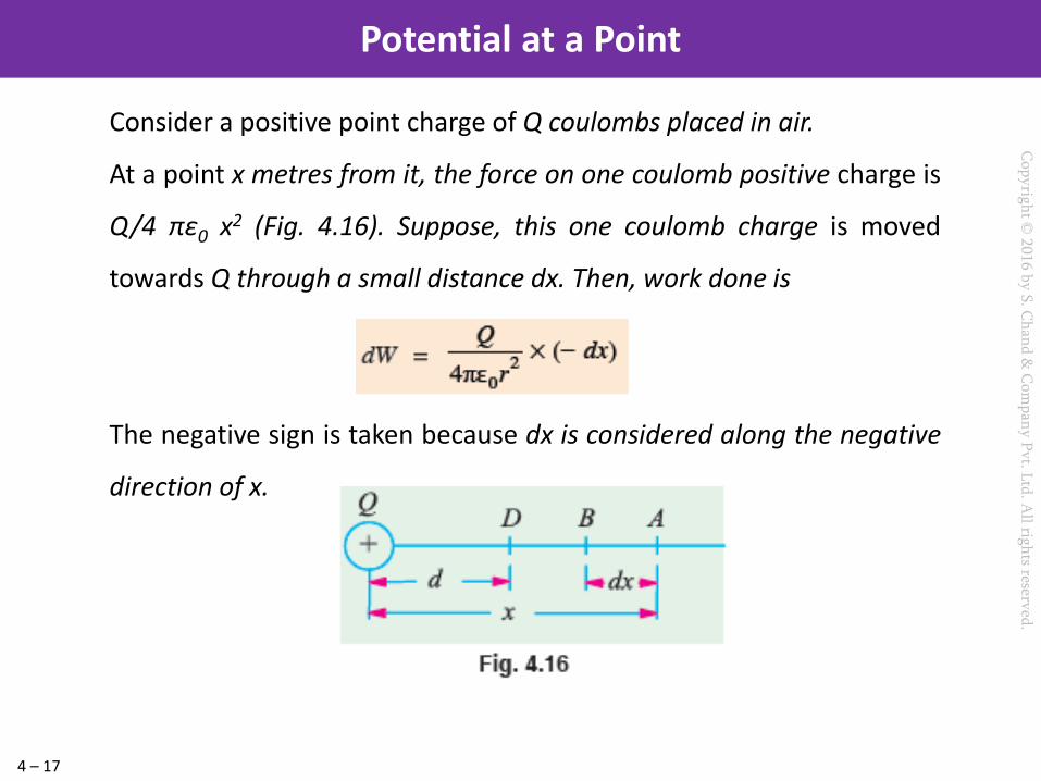
Consider a positive point charge of Q coulombs placed in air.
At a point x metres from it, the force on one coulomb positive charge is
Q/4 πε0 x2 (Fig. 4.16). Suppose, this one coulomb charge is moved
towards Q through a small distance dx. Then, work done is
The negative sign is taken because dx is considered along the negative
direction of x.
Potential at a Point

4 – 18
Cop
yrigh
t © 2016 b
y S. C
han
d &
Com
pan
y P
vt. Ltd
. All righ
ts reserved.
The above formula V = Q/4πε0 εr d applies
only to a charge concentrated at a point.
The problem of finding potential at a point
outside a charged sphere sounds difficult,
because the charge on the sphere is
distributed over its entire surface and so, is
not concentrated at a point. But the
problem is easily solved by nothing that the
lines of force of a charged sphere, like A in
by noting that the lines of force of a
charged sphere, like A in Fig. 4.17 spread
out normally from its surface.
Potential of a Charged Conducting Sphere

4 – 19
Cop
yrigh
t © 2016 b
y S. C
han
d &
Com
pan
y P
vt. Ltd
. All righ
ts reserved.
Equipotential Surfaces
4 – 20
Cop
yrigh
t © 2016 b
y S. C
han
d &
Com
pan
y P
vt. Ltd
. All righ
ts reserved.
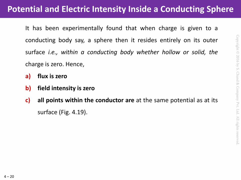
It has been experimentally found that when charge is given to a
conducting body say, a sphere then it resides entirely on its outer
surface i.e., within a conducting body whether hollow or solid, the
charge is zero. Hence,
a) flux is zero
b) field intensity is zero
c) all points within the conductor are at the same potential as at its
surface (Fig. 4.19).
Potential and Electric Intensity Inside a Conducting Sphere

4 – 21
Cop
yrigh
t © 2016 b
y S. C
han
d &
Com
pan
y P
vt. Ltd
. All righ
ts reserved.
It is defined as the rate of change of potential with distance in the
direction of electric force i.e.
Its unit is volt/ metre although volt/cm is generally used in practice.
Suppose in an electric field of strength E, there are two points dx
metre apart. The p.d. between them is
dV = E . (− dx) = − E . Dx − ∴ ...(i)
The −ve sign indicates that the electric field is directed outward, while
the potential increases inward.
Hence, it means that electric intensity at a point is equal to the
negative potential gradient at that point.
Potential Gradient

4 – 22
Cop
yrigh
t © 2016 b
y S. C
han
d &
Com
pan
y P
vt. Ltd
. All righ
ts reserved.
An insulator or dielectric is a substance within which there are no
mobile electrons necessary for electric conduction. However,
when the voltage applied to such an insulator exceeds a certain
value, then it breaks down and allows a heavy electric current
(much larger than the usual leakage current) to flow through it. If
the insulator is a solid medium, it gets punctured or cracked.
The disruptive or breakdown voltage of an insulator is the
minimum voltage required to break it down.*
Dielectric strength of an insulator or dielectric medium is given by
the maximum potential difference which a unit thickness of the
medium can withstand without breaking down.
Breakdown Voltage and Dielectric Strength

4 – 23
Cop
yrigh
t © 2016 b
y S. C
han
d &
Com
pan
y P
vt. Ltd
. All righ
ts reserved.
It is given by the ratio of the dielectric strength of the insulator
and the electric field intensity established in it. If we represent
the dielectric strength by Ebd and the actual field intensity by E,
then safety factor k = Ebd /E
For example, for air Ebd = 3 × 10⁶ V/m. If we establish a field
intensity of 3 × 10⁵ V/m in it, then, k = 3 × 10⁶/3 ⋅ 105 = 10.
Safety Factor of a Dielectric

4 – 24
Cop
yrigh
t © 2016 b
y S. C
han
d &
Com
pan
y P
vt. Ltd
. All righ
ts reserved.
There are discontinuities in electric
fields at the boundaries between
conductors and dielectrics of
different permittivities. The
relationships existing between the
electric field strengths and flux
densities at the boundary are called
the boundary conditions. With
reference to Fig. 4.21, first boundary
conditions is that the normal
component of flux density is
continuous across a surface.
Boundary Conditions