ELECTRICAL EQUIPMENT M.1 GENERAL …lotus-europa.com/manuals/s2work/m/s2m.pdfM 15 SWITCHES 42 M 16...
56
---------------------------------------------------------------------------------------- Section Updated: 10/25/2007 11:09 AM at http://www.lotus-europa.com ---------------------------------------------------------------------------------------- SECTION M ELECTRICAL EQUIPMENT Section Description Page M.1 GENERAL DESCRIPTION 4 M.2 BATTERY 4 M.3 STARTER MOTOR 7 M.4 STARTER SOLENOID 14 M.5 DISTRIBUTOR 15 M.6 IGNITION COIL 20 M.7 SPARKING PLUGS 20 M.8 FUSE UNIT 23 M.9 WINDSCREEN WIPER 23 M. 10 HORN 26 M. 11 LAMPS 29 M.12 DIRECTION INDICATOR SYSTEM 36 M 13 INSTRUMENTS 37 M 14 EARTHING (GROUNDING) OF COMPONENTS 41 M 15 SWITCHES 42 M 16 MOTOR FAN UNIT 44 M 17 ALTERNATOR 46 M 18 VOLTAGE STABILISER 51 M 19 IGNITION COIL 51 M 20 CABLE COLOUR CODING 51 M 21 REVERSE LAMP SWITCH 52 M 22 RADIO 52 M.23 RADIO SUPPRESSION 54 M.24 REVERSE LAMP SWITCH 55
Transcript of ELECTRICAL EQUIPMENT M.1 GENERAL …lotus-europa.com/manuals/s2work/m/s2m.pdfM 15 SWITCHES 42 M 16...

----------------------------------------------------------------------------------------Section Updated: 10/25/2007 11:09 AM at http://www.lotus-europa.com ----------------------------------------------------------------------------------------
SECTION M
ELECTRICAL EQUIPMENT
Section Description Page
M.1 GENERAL DESCRIPTION 4
M.2 BATTERY 4
M.3 STARTER MOTOR 7
M.4 STARTER SOLENOID 14
M.5 DISTRIBUTOR 15
M.6 IGNITION COIL 20
M.7 SPARKING PLUGS 20
M.8 FUSE UNIT 23
M.9 WINDSCREEN WIPER 23
M. 10 HORN 26
M. 11 LAMPS 29
M.12 DIRECTION INDICATOR SYSTEM 36
M 13 INSTRUMENTS 37
M 14 EARTHING (GROUNDING) OF COMPONENTS 41
M 15 SWITCHES 42
M 16 MOTOR FAN UNIT 44
M 17 ALTERNATOR 46
M 18 VOLTAGE STABILISER 51
M 19 IGNITION COIL 51
M 20 CABLE COLOUR CODING 51
M 21 REVERSE LAMP SWITCH 52
M 22 RADIO 52
M.23 RADIO SUPPRESSION 54
M.24 REVERSE LAMP SWITCH 55

PAGE 2 SECTION M – ELECTRICAL EQUIPMENT
----------------------------------------------------------------------------------------Section Updated: 10/25/2007 11:09 AM at http://www.lotus-europa.com ----------------------------------------------------------------------------------------
ILLUSTRATIONS
Fig. No. Page No.
1 Specific Gravity Test 52 The Starter-Motor 73 Components of the Starter-Motor 84 Sectional View of the Starter Motor 85 Starter Motor Mounting Bolts 96 Removing the Front Stop 97 Armature Earthed Circuit Test 118 Armature Open Circuit Test 129 Armature Short Circuit Test 1210 Testing Field Coils for Continuity 1211 Testing Field Coil Insulation 1212 Pole-Shoe Screwdriver 1313 Peaning the End Stop 1314 Starter Solenoid Test 1415 Pinion Clearance 1416 Solenoid Fork 1417 Components of the Distributor 1518 Vacuum Adjustment 1619 Flywheel Ignition Timing Marks 1720 Distributor Drive 1721 Pilot Lamp Test 1822 Distributor Bench Test 1923 Ignition Coil 2024 Plugs - Normal Condition 2125 Worn Condition 2126 Oil Fouling 2127 Petrol Fouling 2228 Burnt Condition 2229 Adjusting Sparking Plug Gap 2230 Fuse Unit 2331 Windscreen Wiper Components 2432 Horn 2633 Horn Adjustment 2734 Air Horns Installation 2835 Tool for Removing Bezel 2936 Headlamp Assembly - U .K. and Europe 3037 Headlamp Assembly - North America 3038 Headlamp Trimming Screws 3239 Head lamp Alignment 3240 Front Flasher Lamps 3341 Series One Rear Lamp Assembly 3442 Series Two Rear Lamp Assembly 3443 Number Plate Illuminating Lamp 3544 Courtesy Light 3545 Side Flasher Lamp 36

SECTION M – ELECTRICAL EQUIPMENT PAGE 3
----------------------------------------------------------------------------------------Section Updated: 10/25/2007 11:09 AM at http://www.lotus-europa.com ----------------------------------------------------------------------------------------
ILLUSTRATIONS
Fig. No. Page No.
46 Internal Connections of Flasher Unit 3747 Series One L.H.D. Facia Panel and Controls 3848 Series Two L.H.D. Facia Panel and Controls 3849 Series Two R.H.D. Facia Panel and Controls 3950 Relay Connections 4251 Steering Lock Connections 4352 Fan Unit Circuit 4453 The Fan Unit Mounting Bolts 4554 Fan Removal 4555 Fan Motor Mounting Bolts 4556 Fan Motor End Plate 4657 Brush Carrier 4658 Soldering Connections 4659 Mostat Test Circuit 4760 Alternator Unit 4861 Alternator Connections 4862 Alternator Mountings 4863 Belt Tension Tool 4964 Reading the Belt Tension 4965 Positioning the Belt Tension Tool 4966 Components of the Alternator 5067 Cable Colour Coding 5168 Cable Colour Coding 5269 Brackets fitted to Receiver and location of Screens 56
PAGE 4 SECTION M – ELECTRICAL EQUIPMENT
----------------------------------------------------------------------------------------Section Updated: 10/25/2007 11:09 AM at http://www.lotus-europa.com ----------------------------------------------------------------------------------------
M.1 - GENERAL DESCRIPTION
The electrical system is a 12-volt earth return type employing NEGATIVE earth polarity. The systemincorporates a charging, lighting, starter, ignition and auxiliary circuits, operating through a fuse unitmounted on the right hand side of the backbone tunnel below the instrument panel. The charging circuitemploys a 30 amp alternator with a separate electronic regulator.
A 57 amp/hour capacity battery is fitted on the right-hand side of the engine compartment, the negativeearth lead of which is bolted directly to the chassis.
An inertia or pre- engaged starter motor is fitted on the left-hand side of the engine and engages with aring gear on the engine flywheel. Electric current is supplied to the starter motor by a solenoid switchmounted on the unit itself and is controlled by the ignition switch mounted on the instrument panel.
The ignition system consists of a distributor mounted on the right-hand side of the engine and driven bythe camshaft, employing a centrifugal ignition advance control, a Ducellier ignition coil, and Marchal 34HS sparking plugs, using suppression caps fitted to each high tension lead.
The two headlamps giving main and clipped beams incorporate the parking lamps. The combined dipand headlamp/flasher switch is mounted on the steering column nacelle.
Separate flasher lamps are mounted on the front of the car inboard of each headlamps assembly. At therear combined rear stop and flasher lamps are fitted, the units also incorporating reflectors.Interior equipment includes electrically operated windows fitted as standard equipment and controlledby independent switches mounted on the instrument panel.
The facia instruments are mounted from the back of the panel, the fuel and temperature gauges being ofthe bi-metal type controlled by a 5 volt regulator mounted behind the panel. An oil pressure gaugeelectrically operated directly from the engine is fitted and an ammeter is also fitted together with acomprehensive set of warning lights.
Single or double two-speed windscreen wipers of the self-parking type are fitted, and electricallyoperated windscreen washers are included in the specification.------------------------------------------------------------------------------------------------------------------------------------------------------------------------------------M.2 - BATTERY.
Description.The battery features a 'clean-top' design with a one-piece manifold venting system. The terminals postsare the flat type drilled to accommodate the bolts passing through the cable connectors.
The battery is mounted in the boot (trunk) and held in position by a clamp. Batteries are supplied eitherfilled and charged or 'dry-charged', that is with the cells in a charged condition and without electrolyte.Details of preparing 'dry-charged' batteries are given in later paragraphs.
Maintenance.1. Battery maintenance consists mainly of regular inspection and servicing. Keep the battery and itssurroundings clean and dry. Give particular attention to the top of the battery to prevent electricalleakage between the terminals.2. Remove the manifold vent cover, and see that the vent holes are clear.

SECTION M – ELECTRICAL EQUIPMENT PAGE 5
----------------------------------------------------------------------------------------Section Updated: 10/25/2007 11:09 AM at http://www.lotus-europa.com ----------------------------------------------------------------------------------------
3. Check the electrolyte level and top up, when necessary. The correct level is just up to the perforatedsplashguard. Do not over-fill or acid will escape through the vent hales with detrimental effect to theconnections and adjacent parts of the car.
The use of a Lucas Battery Filler (or similar) will be found helpful in this topping-up process, as itensures that the correct electrolyte level is automatically obtained and also prevents distilled water frombeing spilled over the top of the battery.
Distilled water should always be used for topping-up. In an emergency, however, drinking water orclean rain water may be used. The following waters must not be used, salt water, chlorinated water,chemically softened water or stagnant water.
Never use a naked light when examining a battery, as the mixture of oxygen and hydrogen given off bythe battery when on charge, and to a lesser extent when standing idle, can be dangerously explosive.
If a battery is found to need an excessive amount of topping-up, the cause should be sought. If anexcessive charge is suspected, check the regulator setting. If one cell in particular is at fault, examine thecontainer for cracks. NEVER transfer electrolyte from one cell to another.4. When fitting the connectors to the battery,first smear the terminal posts with petroleumjelly or silicone grease.5. Examine the earth connection to ensure thatit is clean and free from rust or corrosion.6. Specific gravity Test.Measure the specific gravity of the electrolytein each cell in turn, with a hydrometer. Thereading given by each cell should beapproximately the same; if one cell differsfrom the other by more than .040, an internalfault in the cell is indicated.
If the level of the electrolyte is so low that ahydrometer reading cannot be taken, thebattery should be topped-up with distilledwater and recharged. No attempt should bemade to take a reading after adding thedistilled water until the battery has been oncharge for at least thirty minutes. NEVERtransfer the electrolyte from one cell toanother.
The appearance of the electrolyte drawn into the hydrometer when taking a reading gives a usefulindication of the state of plates; if it is very dirty or contains small particles in suspension, it is possiblethat the plates are in a bad condition.
Check the specific gravity of the electrolyte (see Fig. 1) as an indication of the state of charge of thebattery, using a hydrometer.

PAGE 6 SECTION M – ELECTRICAL EQUIPMENT
----------------------------------------------------------------------------------------Section Updated: 10/25/2007 11:09 AM at http://www.lotus-europa.com ----------------------------------------------------------------------------------------
The specific gravity reading varies with the temperature of the acid electrolyte and it is customary tocorrect it to the corresponding value at a standard temperature of 15 C as follows: For each 10°C. above15° C. add .007 to the reading.
For each l0°C. below 15° C. subtract .007 from the reading.
If the car is out of use for any length of time the battery should not be allowed to run down or to remainin a discharged condition. It should be recharged about every 2 weeks from an independent electricalsupply.7. Heavy Discharge Test.No attempt should be made to carry out a heavy discharge test on this type of battery. The specificgravity test described in the foregoing paragraphs will provide a clear indication of the condition of thebattery, provided the test has been carried out correctly. If any doubt remains, the battery should bechecked by the nearest Exide agent.
Remember that if the battery is subjected to heavy loads (i.e. long periods of night parking with lightson) without suitable opportunities for recharging a low state of charge is only to be expected. A fault inthe charging system or neglect during a period out of commission may also be responsible for anytrouble.
Acid spillage or creepage can be neutralized by wiping the affected area with a fluffless cloth moistenedwith a dilute alkaline solution such as ammonia.
Recharging from an external supply.If test indicate that the battery is discharged, but is otherwise in good condition, it should be re-chargedeither on the vehicle by a period of daytime running or on the bench from an external supply.If the latter, the battery should be charged until the specific gravity and voltage show no increase overthree successive hourly readings. During the charge the electrolyte must be kept level with the top of theseparator guard by the addition of distilled water.
A battery in which all cells show a general failing off in efficiency will often respond to the processknown as 'cycling'. This process consists of fully charging the battery as described earlier, and thendischarging it by connecting to a lamp board, or other load, at the same rate.
Preparing New Batteries.Batteries are normally supplied 'dry-charged' and before fitting to the car must be filled with acid asdescribed under 'Filling the Cells'. No initial charging is necessary, although, if time permits, a shortfreshening charge is advantageous.
Preparation of Electrolyte.Electrolyte of the specific gravity stated in the following table is prepared by mixing distilled water andconcentrated sulphuric acid, usually of 1.840 specific gravity.The mixing must be carried out either in a lead-lined tank or in suitable glass or earthenware vessels.Slowly add the acid to the water, stirring with a glass rod. Never add the water to the acid as theresulting chemical reaction causes violent and dangerous spurting of the concentrated acid. Theapproximate proportions of acid and water are indicated in the following table: - Climates normallybelow 27°C. (80°F.):
Add one part (by volume) of acid of 1.840 specific gravity to 3.2 parts (by volume) of pure distilledwater to obtain a final specific gravity of 1.260 at 15.5°C. acid temperature.

SECTION M – ELECTRICAL EQUIPMENT PAGE 7
----------------------------------------------------------------------------------------Section Updated: 10/25/2007 11:09 AM at http://www.lotus-europa.com ----------------------------------------------------------------------------------------
The specific gravities and their indications are as follows:Climatic temperature of 15° CFully charged 1.28025% discharged 1.24050% discharged 1.20075% discharged 1.160Fully discharged 1.120 and below.
Climates normally above 27° C. (80° F.):Add one part (by volume) of acid of 1.840 specific gravity to 4.3 parts (by volume) of pure distilledwater to obtain a final specific gravity of 1.210 at 15.5° C. acid temperature.Heat is produced by the mixture of acid and water, and the electrolyte should be allowed to cool beforetaking hydrometer readings - unless a thermometer is used to measure the actual temperature, and acorrection applied to the reading as previously described - and before pouring the electrolyte into thebattery.
Filling the Cells.
Whilst these batteries leave the factory in the fully 'dry-charged' condition, they may slowly lose somecharge in storage. In view of this, the following filling instructions must be carefully observed: -With the acid, battery and room temperature between 15.5 - 37.7° C. remove the vent cover or plugs andfill (in one operation] each cell to the separator guard.Measure the temperature and specific gravity of the electrolyte in each of the cells. Allow to stand for 20minutes and then re-check the specific gravity and temperature of the electrolyte in each cell.The battery is then ready for service, unless the above checks show the electrolyte temperature to haverisen by more than 5.5° C. or the specific gravity to have fallen by more than 10 'points' (.010 S.G.).In this event, it will be necessary to re-charge the battery at the appropriate re-charge rate until thespecific gravity values remain constant for three successive hourly readings and all cells are gassingfreely.During charging, keep the electrolyte in each cell level with the separator guard by adding distilledwater - not acid.------------------------------------------------------------------------------------------------------------------------------------------------------------------------------------M.3 - STARTER MOTOR.
The starter motor is a four-pole, two brush unit having an extended shaft, which carries the starter drive,and an integral solenoid switch (see Fig.3).

PAGE 8 SECTION M – ELECTRICAL EQUIPMENT
----------------------------------------------------------------------------------------Section Updated: 10/25/2007 11:09 AM at http://www.lotus-europa.com ----------------------------------------------------------------------------------------
Mechanical Data.Brush length: 1.4 mm (35/64").Minimum brush length: 8 mm (7/16").Commutator diameter: 36.5 mm (1 7/16').Minimum commutator diameter: 34 mm (111/32").Depth of Commutator insulation undercut: 0.5mm (.020").Clearance between front stop and pinion whenoperating: H = 0.5 to 2.5 mm (.020 to .099").

SECTION M – ELECTRICAL EQUIPMENT PAGE 9
----------------------------------------------------------------------------------------Section Updated: 10/25/2007 11:09 AM at http://www.lotus-europa.com ----------------------------------------------------------------------------------------
To remove:1. Disconnect the battery leads (earthfirst).2. Disconnect the starter leads.3. Remove the locking wire from thethree bolts Fig. 5 [1] (fitted to earliervehicles only).4. Undo the nuts and remove the threebolts and washers, which secure thestarter motor to the clutch housing.5. Remove the starter.
To replace:1. Reverse the removal procedure.
Maintenance:The following checking procedureshould be carried out periodically whilstthe starter motor is in service.1. Remove the metal band cover and blow out any dust or sediment with clean compassed air.2. Remove any dirt, which may remain on the brush gear, by applying a petrol-moistened cloth.3. Polish the commutator with a dry fluffless cloth and refit the metal band cover.4. Keep all electrical connections clean and tight. Any which may have become dirty must be cleanedand the contacting surface smeared with petroleum jelly or silicone grease.
Testing the Starter Motor.1. Remove the metal band cover, hold back the brush springs and lift the brushes from their holders.2. Unscrew the nuts from the two through bolts which protrude through the commutator end bracket, andremove the commutator end bracket from the yoke.3. Undo and remove the two bolts securing the solenoid switch unit to the driving end bracket.4. Remove the yoke from the drive end bracket and remove the through bolts.5. Disconnect the solenoid operating fork to release the solenoid switch.6. Remove the drive end bracket from the armature.7. If it is necessary to further dismantle the armature (e.g. to replace the starter pinion) the front stopmust be removed. To remove it, use a tube as shown in Fig. 6 [2] to expose the snap ring.8. Pull off the starter pinion assembly.

PAGE 10 SECTION M – ELECTRICAL EQUIPMENT
----------------------------------------------------------------------------------------Section Updated: 10/25/2007 11:09 AM at http://www.lotus-europa.com ----------------------------------------------------------------------------------------
Brushgear.Check that the brushes move freely in their holders by holding back the brush springs and pulling gentlyon the flexible connectors. If movement is sluggish remove the brush from its holder and clean its sideswith a fiuffless petrol-moistened cloth. Replace the brush in its original position. Brushes which areworn to .3125 in. (8 mm.) in length must be renewed. The brushes are preformed so that bedding to thecommutator is unnecessary. Check the tension of the brush springs by means of a spring scale. Thecorrect tension is given in 'Technical Data'. New springs must be fitted if the tension is low.Check the tension of any new spring and ensure that it makes contact with the centre of the brush top.
Commutator.
A commutator in good condition will be smooth and free from pits and burned spots. Clean thecommutator with a petrol-moistened cloth. If this is ineffective, carefully polish with a strip of fineemery paper, while rotating the armature.To remedy a badly worn commutator, dismantle the starter drive as described in later paragraphs andremove the armature from the end bracket. Mount the armature in a lathe, rotate at high speed and take alight cut with a very sharp tool. Do not remove any more metal than is necessary. Finally polish withvery fine emery paper.The insulators between the commutator segments must not be undercut.
Armature.
An armature can be tested for open circuits, short circuits, and earthed circuits, by following theprocedure described below:Before carrying out the tests, check for lifted commutator segments and loose turns in the armaturewinding.These may be due to the starter motor having remained engaged while the engine was running, thuscausing the armature to be rotated at excessive speed.A damaged armature must always be renewed. No attempt should be made to machine the armature coreor to true a distorted armature shaft. An indication of a bent shaft or a loose pole shoe may be given byscored armature laminations.
Open circuit test:
An open circuit, as the term implies, is a break in the armature windings. This defect is characterized byviolent sparking at the commutator segment, or in the armature winding, the more usual causes being:1. Overloading, causing excessive heating and melting out of the solder from the commutator risers.2. Vibration sufficient to break the commutator connections.

SECTION M – ELECTRICAL EQUIPMENT PAGE 11
----------------------------------------------------------------------------------------Section Updated: 10/25/2007 11:09 AM at http://www.lotus-europa.com ----------------------------------------------------------------------------------------
3. Poor connections, which have become oxidized.4. An earth or short-circuit, burning open the winding.5. A mechanical defect causing the armature to rub on some sundry part of the machine.Using a 12-volt battery and a voltmeter with test prods make the connections shown in Fig.8 [13]. Placethe voltmeter test prods on each pair of adjacent commutator segments in turn and note the voltmeterreadings. If the armature is in good order, all readings will be similar, but if between any pair ofsegments a low or zero reading is obtained, one or more adjacent coils are open circuited.
Short circuit test:
Discoloration of any one or two coils, and blackening of two or more commutator segments is a sign ofa short circuit. The usual causes are as follows:1. Carbon or copper dust having become lodged between the commutator segments.2. Solder particles getting behind the commutator.3. An overload, resulting in excessive heating, causing the insulation to break down.4.The insulation becoming damaged.Place the armature in a 'Growler' as shown in Fig.9. Energize the 'Growler' and hold a narrow piece ofsteel strip over the top of the armature, keeping the steel strip in the same position. If a short circuitexists, the steel strip will be heavily attracted towards the slot containing the faulty coil. If the attractionis particularly heavy, switch off the 'Growler' quickly otherwise the coil may be entirely burnt out.Remember that a coil is wound in two slots, so that on turning the armature further, a second faulty slotwill be found.
Earthed circuit test:An earthed circuit in the armature is caused by a breakdown in the insulation, which will allow apassage of current to the generator frame. Such a breakdown can be attributed to one or more of thefollowing defects:1. Dirt and carbon dust collecting behind the commutator risers.2. The armature rubbing the field pole-faces, causing the laminations to rub into the armature wires.3. By the laminations of the armature becoming loose anti rubbing into the armature wires.
4. Overheating due to the machine having been run on an open circuit.Using a 12-volt battery, voltmeter andtest prods, make the test connectionsshown in Fig.7. Keep one test prod incontact with the end of the armatureshaft and place the other on eachcommutator segment in turn.There should be no voltmeter readings.Any segment on which a reading isobtained will be connected to thearmature coil nearest an earth fault.An alternative method is to use a testlamp instead of a volt meter - the lampwill glow if there is an earth.
5. Unscrew the two pole-shoe retainingscrews by means of a pole-shoe screwdriver as shown in Fig. 12. [3]

PAGE 12 SECTION M – ELECTRICAL EQUIPMENT
----------------------------------------------------------------------------------------Section Updated: 10/25/2007 11:09 AM at http://www.lotus-europa.com ----------------------------------------------------------------------------------------
6. Draw the pole-shoe coils out of the yoke and lift off the coils.7. Fit the new field coils over the pole-shoes and place them in position inside the yoke. Take care toensure that the taping of the field coils is not trapped between the pole-shoes and the yoke.8. Locate the pole-shoes and field coils by lightly tightening the fixing screws.9. Fully tighten the screws by means of the pole-shoe screwdriver.10. Solder the terminal blade and earthing eyelet to the appropriate coil enes.11. Refit the insulating sleeve and re-rivet the terminal assembly to the yoke.12. Refit the insulation piece behind the junction of the two coils.
Field Coils.Continuity test:If the lamp fails to light in the following test, an open circuit in the field coils is indicated and thedefective coils must be renewed.1. Connect a 12-volt battery and bulb in series with two pointed test prods.2. When the prods are placed on the brush tappings, the bulb should illuminate. Lighting of the lampdoes not necessarily indicate that the field coils are in order. It is possible that a field coil may be earthedto a pole-shoe or to the yoke.
Insulation test:Connect a 110-volt A.C. test lamp between the terminal post and a clean part of the yoke. Lighting ofthe lamp indicates that the field coils are earthed to the yoke and must be renewed.Measure the resistance of the field coils without removing them from the starter yoke, by means of an
ohmmeter connected between the field terminal and the yoke. The field resistance is given in 'TechnicalData'.If an ohmmeter is not available, connect a 12-volt D.C. supply between the field terminal and the starteryoke, with an ammeter in series. The ammeter reading should be approximately 2 amperes. Zero readingon the ammeter, or an 'infinity' ohmmeter reading, indicates an open circuit in the field winding.If the current reading is much more than 2 amperes, or the ohmmeter reading is much below 6 ohms,this is an indication that the insulation of one of the

SECTION M – ELECTRICAL EQUIPMENT PAGE 13
----------------------------------------------------------------------------------------Section Updated: 10/25/2007 11:09 AM at http://www.lotus-europa.com ----------------------------------------------------------------------------------------
field coils has broken down.In either event, unless a substitute starter motor is available the field coils must be renewed. To do this,carry out the procedure outlined as follows:1. Drill out the rivet securing the field coil terminal assembly to the yoke and remove the insulatingsleeve from the terminal blade.2.Unsolder the terminal blade and earthing eyelet.3.Remove the insulation piece, which is provided to prevent the junction of the field coils fromcontacting the yoke.4. Mark the yoke and pole-shoes so that the latter can be fitted in their original, positions.
Renewing the field coils:This operation should be carried out with the aidof a pole-shoe screwdriver as illustrated in Fig.12.1. Using the pole-screw screwdriver, unscrewthe four pole-shoe retaining screws.2. Remove the insulation piece, which is fittedto prevent the intercoil connectors fromcontacting the yoke.3. Mark the yoke and pole-shoes in order thatthey may be refitted in their original positions.4. Draw the pole-shoes and coils out of the yokeand lift off the coils.5. Fit the new field coils over the pole-shoes andplace them in position inside the yoke. Ensurethat the taping of the field coils is not trappedbetween the pole-shoes and the yoke.6. Locate the pole-shoes and field coils bylightly tightening the fixing screws.7. Refit the insulation piece between the field coil connections and the yoke.8. Finally, tighten the screws by means of the pole-shoe screwdriver.
Assembly.
Assembly is a reversal of the procedure outlinedabove.
When refitting the starter pinion assembly to thearmature shaft, a new front stop must be fittedand the following points taken intoconsideration.
1. The snap rings must be covered by the stop.2. The end of the stop must be peaned down atfour points as shown in Fig. 13 to trap the snap-rings in place.

PAGE 14 SECTION M – ELECTRICAL EQUIPMENT
----------------------------------------------------------------------------------------Section Updated: 10/25/2007 11:09 AM at http://www.lotus-europa.com ----------------------------------------------------------------------------------------
M.4 - STARTER SOLENOID.
Adjusting the travel of the solenoid switch operating fork.
Energize the solenoid as shown in Fig. 14. [10]
N.B. - Field coil feed terminal (1) must not beconnected up. [11]
The pinion (2) will then come into its operating position and thereshould be a clearance H of between 0.5 and 2.5 mm. (.020"to .099") between the pinion (2) and the stop (3).
If the clearance is not correct, remove the switch and screw thefork end (4) in or out to obtain the correct clearance.

SECTION M – ELECTRICAL EQUIPMENT PAGE 15
----------------------------------------------------------------------------------------Section Updated: 10/25/2007 11:09 AM at http://www.lotus-europa.com ----------------------------------------------------------------------------------------
M.5 - DISTRIBUTOR.
Contact Breaker Assembly.At the free After Sales Services (300 miles - 500 km. and 1,200 miles - 2,000 Km.) then
subsequently every 3,000 miles (5,000 km.) the contact breaker should be checked and adjusted ifnecessary.The distributor points gap can be adjusted in one of two ways:1 - by measuring the Dwell angle by means of a Dwell Meter. This instrument, adaptable from 6 to 12volts is a standard item of workshop test equipment a and can be used to carry out this measurementeither on the test bench or directly on the vehicle without removing the distributor.

PAGE 16 SECTION M – ELECTRICAL EQUIPMENT
----------------------------------------------------------------------------------------Section Updated: 10/25/2007 11:09 AM at http://www.lotus-europa.com ----------------------------------------------------------------------------------------
2 - by measuring the points gap with a set of feeler gauges described below: -Engage 4th gear.Rotate one of the road wheels in the forward drive direction, until the contact breaker points are
fully opened and check the gap with a gauge having a thickness of from .016 in. to .019 in. (41 mm to 49mm.) If the gap is correct the gauge should be a sliding fit. Do not alter the setting unless the gap variesconsiderably from the gauge thickness.To adjust the setting, keep the engine in the position, which gives maximum opening of the contacts andthen slacken the screw securing the fixed contact plate.Adjust the position of the plate until the gap is set to the thickness of the gauge and then tighten thelocking screw. Remember that the cam only keeps the contact points fully open over a very small angleand that care must be taken to ensure that the points are in the fully open position.Cover the hole on the vacuum capsule with the finger and apply the maximum vacuum to the capsulethrough a vacuum gauge (one can also operate the rod secured to the diaphragm, and to the cam carrierplate by hand).Check that there is the same gap between the two extreme positions of the points i.e.; without vacuumand with maximum vacuum, if this is not the case, turn the cam (see fig. 18) by means of the special key46M 6184. After carrying out this adjustment re-check that the points gap is still correct.If the contacts are dirty or pitted, they must be cleaned bypolishing them with fine Carborundum stone andafterwards wiping them with a petrol moistened cloth.The moving contact can be removed from its mounting inorder to assist cleaning.Check and adjust the contact breaker setting aftercleaning the contacts.Check that the moving arm moves freely on its pivot. If itis sluggish remove the moving arm and polish the pivotpin with fine emery cloth. Afterwards clean off all traceof emery dust and apply a spot of clean engine oil to thetop of the pivot.The contact breaker spring tension is given in 'Technical Data'.
To Remove the Contact Breaker.1. Unclip and remove the distributor cap.2. Remove the rotor arm.3. Undo the nuts securing the low tension and condenser leads to the terminal post sufficiently to releasethe slotted spade end of the lead to the breaker arm.4. Remove the hair pin clip and withdraw the breaker arm from the pivot post complete with its lead.5.Undo the fixing screw and remove the adjustable contact.
To Replace the Contact Breaker.1. Locate a new adjustable contact over the guide post and loosely fit the retaining screw.2. Check that the terminal post is fitted correctly into its insulated mounting from within the body of thedistributor.3. Interpose the slotted spade end of the contact breaker lead between the square head of the post and theinsulated mounting.

SECTION M – ELECTRICAL EQUIPMENT PAGE 17
----------------------------------------------------------------------------------------Section Updated: 10/25/2007 11:09 AM at http://www.lotus-europa.com ----------------------------------------------------------------------------------------
4. If the leads and nuts have been removed during dismantling it is essential that they be assembled inthe correct order. Proceed as follows: -From outside the distributor body add 1/ the insulating washer; 2/ plain washer; 3/ the eyelet terminalend of the black condenser lead; 4/ plain washer; 5/ spring washer secure with 6/ the larger nut (10 mmspanner size); add 7/ the eyelet terminal end of the white/black lead; 8/ lockwasher.Secure with 9/ the smaller nut (7 mm. spanner size).5. Fit the breaker arm to the pivot post and secure with the hair-pin clip. Ensure that the leaf spring ofthe breaker arm is located within the insulation notch.6. Adjust the points gap to .016 in. to .019 in. (.41 to .49 mm ) and check gap without vacuum and withmaximum vacuum as in previous paragraph.
To Remove Distributor.1. Remove the distributor cap.2. Disconnect the white/black low tension lead.3. Unscrew the bolt retaining the distributor clamp on the engine and carefully withdraw the distributor.
To Replace the Distributor and Time the Ignition (Pilot lamp method).1. Engage 4th gear.2. Raise the rear right-hand or left-hand road wheel.3. Rotate the road wheel in a forward drive direction until the timing mark on the flywheel is at 4°B.T.D.C. The timing pointer is attached to the flywheel bell housing immediately behind and to the rightof the camshaft pulley. Ensure that the first cylinder i.e., at the clutch end is on the compression stroke.
4. In this position, the distributor drive pinion must be positioned so that its smallest offset is on theengine side.5. Refit the distributor.6. Remove the distributor cover and connect a 12 v. bulb between the L.T. terminal on the distributorbody and a good earth.7. With the battery connected up, switch on the ignition.8. Turn the distributor in an anti-clockwise direction until the bulb is illuminated. The contact breakerpoints will then be open.

PAGE 18 SECTION M – ELECTRICAL EQUIPMENT
----------------------------------------------------------------------------------------Section Updated: 10/25/2007 11:09 AM at http://www.lotus-europa.com ----------------------------------------------------------------------------------------
9. Slacken the distributor clamp bolt and rotate the body in an anti-clockwise direction, enough to closethe points. Move the body in a clockwise direction again until the lamp just lights, then relock the clampbolt.
To Time the Ignition Stroboscopic Lamp Method.The use of this method enables the ignition timingto be checked when the engine is running.When correctly connected, this type of timinglamp gives a high intensity flash each time No. 1cylinder (flywheel end of engine) fires, and whenthe beam is projected onto the flywheel thisappears to be "stationary" white the engine isrunning. It is therefore possible to "see" what theignition timing is with the engine running, and ifnecessary, to adjust the timing without stoppingthe engine.
Disconnect the vacuum advance pipebefore checking the ignition timing with astroboscopic lamp, to ensure that the vacuumadvance has not begun to operate, thus giving a false setting. Neither should this check be made at ahigh idling speed.Distributor Overhaul.To Dismantle:1. Remove the distributor.2. Remove the rotor.3. Undo and remove the terminal post from its location in the distributor body.4. Remove the contact breaker points.5. Uncouple the vacuum capsule and remove the unit.6. Remove the condenser.7. Undo the remaining two screws securing the breaker plate to the body and withdraw the plate.8. Undo the 'C' clips at the advance weight pivots.9. Remove the felt pad and unscrew the centre screw and remove the cam.10. Disconnect and remove the advance springs.11. Remove the advance weights.12. Drive out the retaining pin and remove the driving dog and thrust washers from the distributor shaft.13. Withdraw the distributor shaft from the body.14. Remove the spacer washers.15. Using a suitable mandrel located at the body end-drive out the bush.
To Assemble:Reverse the procedure outlined above.

SECTION M – ELECTRICAL EQUIPMENT PAGE 19
----------------------------------------------------------------------------------------Section Updated: 10/25/2007 11:09 AM at http://www.lotus-europa.com ----------------------------------------------------------------------------------------
Distributor Test (off the vehicle)The following instructions indicate the general principles to be followed for testing the distributor
on a tester. The method of testing, however, may vary for machines of different manufacture. Forspecific instructions refer to the equipment manufacturer's handbook.1. Mount the distributor on the tester, and connect the drive from the machine to the distributor dog.Check that the distributor is free to rotate.2. Make the necessary electrical connections (terminal AL on the instrument illustrated to the distributorfeed terminal).3. Turn the distributor cam by hand to place the contacts in the closed position and turn the zeroing knobon the instrument to place the pointer on the graduation 100.Turn the cylinder selector to four, corresponding to the number of lobes on the cam of the distributor.4. Run the distributor at approximately l000 rev/min (crankshaft).The number of graduations shown on the instrument give the direct Dwell angle reading.
5. Adjust the distributor points to obtain thefollowing Dwell angle reading.- New distributor = 61° +- 3°. Increase the speedup to a maximum of 5,000 rev/min. (crankshaft)and check the dwell reading which must again be61° +- 3°. If the reading is more than 3° out,check for a worn distributor shaft or bushings.
Mechanical Operation.1. Make the necessary connections for thestroboscopic timing light or sparking protractor,refer to equipment manufacturer's handbook.2. Adjust the speed control to vary the distributorspeed between 400 and 500 rev./min. (crankshaft).Erratic or thin faint flashes of light preceding theregular flashes as the speed of rotation is
increased can be due to weak breaker arm spring tension.3. Operate the distributor at approximately 2,500 rev./min. (crankshaft).4. Move the protractor scale with the adjustment control so that the zero degree mark on the scale isopposite one of the neon flashes. The balance of all the flashes should come plus or minus 1°, evenlyspaced around the protractor scale. A larger variation than 1° or erratic or wandering flashes may becaused by a worn cam or distributor shaft or a bent distributor shaft.
Distributor Spark Advance.The spark advance is checked to determine if the ignition timing advances in proper relation to enginespeed and load.Normally this should not require adjustment as it is pre-set during manufacture. However, incorrectassembly, weakening of the advance springs or wear will change curves and rectification will benecessary if engine performance is not to be affected.

PAGE 20 SECTION M – ELECTRICAL EQUIPMENT
----------------------------------------------------------------------------------------Section Updated: 10/25/2007 11:09 AM at http://www.lotus-europa.com ----------------------------------------------------------------------------------------
1. Operate the distributor in the direction of rotation (clockwise) [4] and adjust the speed to 300 rev./min.(distributor). Move the protractor scale so that one of the flashes lines up with the zero degree mark.2. Slowly increase the speed and check the advance at the other speeds quoted in the specification.Operate the distributor both up and down the speed range.
M.6 - IGNITION COIL.To Remove.1 Disconnect the leads from the coil (white/black fromterminal "RUP" and two white leads from terminal "BAT')(see Fig.23).2. Disconnect the red H.T. cable to distributor by slidingthe protective sleeve back and pulling the cable from thesocket.3. Release the two securing bolts and remove the coil.
To Replace.1. Reverse the procedure outlined above.2. Connect the leads to the coil, noting the coil polarity.
Fig.23 - Ignition Coil.
M.7 - SPARKING PLUGS.
To maintain peak sparking plug performance, the plugs should be cleaned and their points adjustedevery 6,000 miles (10,000 km.). The plugs should be renewed at intervals of every 12,000 miles (20,000km.). Under certain fuel and operating conditions, particularly extended slow-speed town driving,sparking plugs may have to be serviced at shorter intervals.
General:Gap:The sparking plug gaps, when correctly set, ensure good ignition under all conditions of engineoperation. If the gaps are set, or become too wide, misfiring can occur and cold starting may becomedifficult. Plug gaps set close can cause rough idling and misfiring. Set gaps to the dimension given in'Technical Data'.
Operating temperature:Sparking plugs that run too cold will become fouled with combustion deposits under town drivingconditions, and plugs that run too hot will fail under hard motorway driving. These failures can also becaused by engine faults producing conditions that the plugs cannot withstand.Sparking plug temperature is controlled by the construction of the-plug insulator, particularly inside theplug body. The insulator of a correct plug, operating under conditions for which the plug was chosen,will allow sufficient heat flow to give the plug a normal life, and also retain enough heat to keep theplug insulator clean inside the plug body. This ensures that the sparking plugs will operate correctly fortheir recommended servicing period.

SECTION M – ELECTRICAL EQUIPMENT PAGE 21
----------------------------------------------------------------------------------------Section Updated: 10/25/2007 11:09 AM at http://www.lotus-europa.com ----------------------------------------------------------------------------------------
Heat range:Sparking plug manufacturers grade their plugs into 'cold' and 'hot', or 'hard' and 'soft' ranges. From thesea suitable plug is chosen as specified in 'Technical Data'.
Corona discharges:This discharge can only be seen in darkness and must not be mistaken for HT discharge shorting acrossthe sparking plug insulator. When occurring, it is seen as a faint blue light in the plug insulator above theplug metal body, and is caused by the HT field in the plug insulator.Corona discharge can repel dust particles from the plug insulator so that a clean band is seen around theinsulator above the plug body. It is a mistake to think that this is evidence of gas leakage past theinsulator if the clean band on the insulator is caused by this discharge.
To Remove.1. Clean the area around each plug to ensure that no foreign matter can enter the cylinder.2. Disconnect the plug leads and remove plugs.
Inspection.
NORMAL CONDITION - Look for powdery deposits ranging from brown to grayish tan. Electrodesmay be slightly worn. These are signs of sparking plugs used under normal conditions of mixed periodsof high and low speed driving.Cleaning and re-gapping of the sparking plugs is all that is required (seeFig. 24). White to yellowish powdery deposits usually indicate longperiods of constant speed service.These deposits have no effect on performance if the sparking plugs arecleaned thoroughly and the gaps reset at the recommended intervals.More frequent cleaning may be needed if the car is only used for shortruns.
WORN CONDITION - This is illustrated in Fig.25. Any spark plugs foundin this condition should be replaced by the correct type given in 'TechnicalData'. A complete set should be fitted.
OIL FOULING - Is usually identified by wet sludge deposits traceable toexcessive oil entering the combustion chamber through worn rings andpistons, excessive clearances between intake valve guides and stems or wornbearings etc. (see Fig. 26).The excessive use of upper cylinder lubricant can also cause fouling.

PAGE 22 SECTION M – ELECTRICAL EQUIPMENT
----------------------------------------------------------------------------------------Section Updated: 10/25/2007 11:09 AM at http://www.lotus-europa.com ----------------------------------------------------------------------------------------
PETROL FOULING - Is usually identified by dry black fluffy deposits,which result from incomplete combustion (see, Fig.27). Too rich an air-fuelmixture or incorrect use of the choke can cause incomplete burning, inaddition defective contact breaker points or H.T. cables can reduce voltagesupplied to the sparking plug and cause misfiring.If fouling is evident, sticking valves may be the cause. Excessive idling,slow speeds or stop-and-go driving can also keep plug temperature so lowthat normal combustion deposits are not burned off.
BURNED OR OVERHEATED – Burning or overheating of the sparkingplug is usually identified by a white burnt or blistered insulator nose andbadly eroded electrodes (see Fig. 28). Inefficient engine cooling ad incorrectignition timing can cause general overheating. If only a few sparking plugsare overheated, the cause may be uneven distribution of the coolant, Severeservice, such as sustained high speed and heavy loads, can also produceabnormally high temperatures in the combustion chamber, whichnecessitates use of colder running sparking plugs.
Cleaning, Testing and Adjustment:Plugs should be cleaned in a dry abrasive cleaning machine and then tested under pressure.Excessive cleaning time must be avoided because the abrasive cleaning action can erode the electrodeinsulator. Before testing, the sparking surfaces of the electrodes should be lightly filed to remove alltraces of burning and to restore flat parallel sparking surfaces. The gap should then be set to therecommended dimension given in 'Technical Data'.The gap setting of sparking plugs is very important and adjustment is made by bending the earthelectrode with a combined gauge and setting tool, as shown in Fig. 29.
After cleaning and gap setting the plug threads should bewire brushed to remove any accumulation of carbon orabrasive material. A small quantity of graphite greaseshould be put on each sparking plug thread before theplugs are replaced.
To Replace.1 Refit the plugs, tightening them to the torque loadinggiven in 'Technical Data'. Reconnect the plug leads.

SECTION M – ELECTRICAL EQUIPMENT PAGE 23
----------------------------------------------------------------------------------------Section Updated: 10/25/2007 11:09 AM at http://www.lotus-europa.com ----------------------------------------------------------------------------------------
M.8 - FUSE UNIT.
Description.The fuse unit is mounted on the right-hand side ofthe back bone tunnel below the instrument paneland is readily accessible from within the vehicle.The unit is of plastic construction having arectangular base with an integrally moulded fusecompartment.The fuse compartment houses two fuses, whichare held by clips terminated in 'Lucar' connectors.Two spare fuses are carried in the fuse block, thewhole unit being protected with a push-on plasticcover. (Fig. 30).If reference is made to the wiring diagrams (at theend of this Section) [5], it will be seen whichcircuits are protected by the fuses.
To Remove.1. Disconnect the battery.2. Note positions of all cables, then pull off from the 'Lucar' terminals.3. Remove fuse unit from car, by unscrewing the central cross head securing screw.
To Replace.1. The fuse unit cannot be repaired so can only be replaced with a new unit.2. To replace a blown fuse unclip the cover and remove the fuse from its spring clips, push the new fusein place an/ replace the cover (obtain replacement 35 amp. fuse if spare is used.)------------------------------------------------------------------------------------------------------------------------------------------------------------------------------------M.9 - WINDSCREEN WIPER.
Description.The windscreen wiper motor comprises a two-speed electric motor and gearbox driving a cable rackmechanism, which transmits power to the wheelbox spindles and so to the wiper arms and blades.Rotation of the motor armature is converted to a reciprocating motion of the cable rack by means of asingle-stage worm and gear, a connecting rod and a cross-head contained in a guide channel.
A switching feature ensures that the arms and the blades return automatically to the 'park' positionirrespective of their positions at the instant of switching off. This is effected by a limit switch in thegearbox, its action being controlled by the crankpin. For the greater part of each stroke the limit switchcontacts are closed, providing and earth return for the motor current parallel to the facia switch. Eachtime the blades reach their position at which they are normally parked when the wiper is not in use, thelimit switch opens. Thus, when the control switch is selected OFF, the motor continues to run until theblades reach their parked position.
Service.The windscreen wiper motor is greased during manufacture and no maintenance is required.The wiper blades operation and arc should be checked at intervals of every 6,000 miles (10,000
km.).

PAGE 24 SECTION M – ELECTRICAL EQUIPMENT
----------------------------------------------------------------------------------------Section Updated: 10/25/2007 11:09 AM at http://www.lotus-europa.com ----------------------------------------------------------------------------------------

SECTION M – ELECTRICAL EQUIPMENT PAGE 25
----------------------------------------------------------------------------------------Section Updated: 10/25/2007 11:09 AM at http://www.lotus-europa.com ----------------------------------------------------------------------------------------
Testing and Adjusting.
Measuring supply voltage:Using a moving-coil voltmeter, measure the voltage between the motor supply terminal and a good
earthing point. This should be 13.5 + .25 volts with the wiper working normally. If the reading is low,check the battery switch (by substitution), cabling and connections.
Measuring light running current and speed:Connect a moving-coil ammeter in the motor supply cable and measure the light running current. Alsoobserve the operating speed by timing the speed of rotation of the rotating crank. With the linkagesystem connected, the light running current should not exceed 1.5 amperes with the wiper operatingswitch in the 'NORMAL' speed position. With the switch in the 'HIGH' speed position, the currentshould not exceed 2.0 amperes.
The gear speeds should be:NORMAL 46 - 52 r.p.m.HIGH 60 - 70 r.p.m.
It is important to note that the two-speed effect is only apparent when the screen is very wet. Thisis quite normal and is due to the decrease in motor torque when 'HIGH' speed is selected at the switch.
Removing and Replacing.Motor:1. Disconnect the battery.2. Undo the clip retaining the flexible hose from the de-mist nozzle to the heater unit adjacent to thewiper motor.3. Pull the hose from the nozzle and heater outlet and remove it.4. Release the nut securing the bundy tubing to the wiper motor.5. Release the setscrews securing the mounting strap, supporting the motor meanwhile. Ease the motorfrom its mounting withdrawing the rack from the wheel box and bundy tubing.6. When the wiper motor unit is sufficiently clear of obstruction, disconnect the leads at the motor.7. Replacement is a reversal of the removal procedure, but ensure that the rack is adequately greasedbefore refitting.
Blade:1. Lift blade and arm clear of the screen, then from underside of arm raise spring clip and pull off blade.2. When replacing, ensure the locating 'pip' on arm is fully entered into the hole on the underside ofblade.
Arm:1. Lift the spring retaining clip and slide the arm from the spindle.2. Operate the wiper for a few moments then switch 'OFF'. This action will allow the wiper spindle toautomatically return to the 'park' position, provided the ignition has remained in the 'ON' position.3. Refit the arm in the 'park' position, operate the wiper and check the arc of operation. The serrations onthe wiper spindle provides 5° adjustment steps for the arm.
Wheelbox:1. Disconnect the battery.2. Remove the wiper arm and the wiper motor.3. From the wiper spindle remove the nut, washer and rubber bush securing the wheelbox to the body.

PAGE 26 SECTION M – ELECTRICAL EQUIPMENT
----------------------------------------------------------------------------------------Section Updated: 10/25/2007 11:09 AM at http://www.lotus-europa.com ----------------------------------------------------------------------------------------
4. From behind the facia, pull the wheelbox from its location, passing down into the car from above theheater unit.5. Replacement is a reversal of the removal procedure, but ensure the rubber bushes are correctly fittedto the contour of the body.
Wiper Arm and Blade.1. When the sharp wiping edge of the, blade wears off, it becomes rounded so that it is unable to removeatmospheric film or smear from the windscreen.Use methylated spirits to remove oil, tar spots and other stains from the windscreen. Silicone and wax-based polishes must not be allowed to contaminate the screen or wiper blades.2. Blades are normaliy made from natural rubber, which is the best possible material for cleaningscreens, but exposed to the elements at the front of the car, this often deteriorates with age. The warningsigns are perishing or cracking, both of which indicate the need for replacement.3. Check the metal harness for wear. Worn arm connectors and worn blade clips can cause the blade tolay over excessively. This not only means a poor wipe because the blade is at an incorrect angle, but canalso result in scratched windscreens.4. Rough handling of the wiper arm - particularly while washing the car - can cause twists, and bends inthe arm or blade connector. This stops the blade flowing the contour of the screen properly.5. It is important that the blade should be applied to the screen at the correct, pressure. This pressure istransmitted to the blade via the arm hinge. The action must be free of binds and apply firm pressure atthe blade connection. The hinge points should therefore be checked for corrosion or wear.
Windscreen Washer.A manual type windscreen washer is fitted as standard equipment to the vehicle. This is a combinedcontrol assembly consisting of a washer pump and the wiper switch, the control knob for the wipers alsoactuating when depressed, the bellows of the pump.Where either the switch or the pump becomes defective it will be necessary to renew the completeassembly, which is retained in the facia by a slotted ring nut. This nut can be removed, after the removalof the control knob, by making up a small tool to engage the slots of the nut. Using a 2 in. (5.1 cm.)length of .75 in (19 mm.) O/D, 14 SWG (.08 in.; 2.03 mm.) steel tubing, one end of which should havetwo lugs ground to engage the slots in the nut. To the other end is welded a small bar to form a 'T'shaped tool.------------------------------------------------------------------------------------------------------------------------------------------------------------------------------------M.10 - HORN.
Description.The Lotus Europa is fitted with a Clear Hooters miniaturewind-tone horn, operated on the well known principle ofa resonating air column vibrated by means of adiaphragm actuated electro-magnetically by a selfinterruptory circuit.
Maintenance.Before being passed out from the manufacturers, everyhorn is adjusted to give its best performance. It shouldrequire no further attention until it has given a longperiod of service.

SECTION M – ELECTRICAL EQUIPMENT PAGE 27
----------------------------------------------------------------------------------------Section Updated: 10/25/2007 11:09 AM at http://www.lotus-europa.com ----------------------------------------------------------------------------------------
If the horn fails to sound or its performance becomes uncertain, the fault may not necessarilybe in the horn. First see that the trouble is not due to such defects as a loose or broken connection in thewiring of the horn circuit or to a discharged battery.A short circuit in the horn wiring will cause the fuse (when fitted) to blow. In this event, examine thewiring for the fault and rectify accordingly, before renewing the fuse with the spare provided. A checkshould also be made to see that the green earth lead is a tight fit in its connector (to boost fan).If the examination shows the above points to be in order the horn may need adjustment but this shouldnot become necessary until the horns have been in service for a long period.
To Remove.1. Detach the two leads (green and purple/blue).2. Release the two nuts and bolts securing the horn mounting bracket. The two nuts will be found withinthe nearside front wheel-arch.Note the penny washers beneath the securing nuts.3. Remove the horn unit as an assembly.
To Replace.Replacement is a reversal of the above procedure.
AdjustmentIt should be noted that adjustment does not alter the pitch of thenote but merely takes up wear of moving parts.While adjusting, short out the fuse (if fitted), otherwise it mayblow. If a horn does not soundafter making an adjustment, release the horn push instantly.A small serrated adjustment screw is provided on the side of thehorn at which the leads terminate. Turn this screw anti-clockwiseuntil the horn just fails to sound, then turn it back for about aquarter of a turn.Note: a 12-volt horn in correct adjustment will pass 3.0 - 3.5ampers; measured on a first grade moving coil 3-10 A ammeter.If a suitable instrument is available, connect it in series with thehorn and turn the adjustment screw clockwise to increase thecurrent, or anti-clockwise to decrease it.When adjusting a horn with the aid of an ammeter, the aim isobtain the best performance with the least current.
AIR HORNS (optional extra).
Description.The air horn kit consists of two matched trumpets and a compressor, which is energized through a relayand switch.
Maintenance.No maintenance is required in service other than the application of a few drops of light oil to thecompressor at intervals of every 3,000 miles (5,000 km.) through the orifice marked 'OIL'.

PAGE 28 SECTION M – ELECTRICAL EQUIPMENT
----------------------------------------------------------------------------------------Section Updated: 10/25/2007 11:09 AM at http://www.lotus-europa.com ----------------------------------------------------------------------------------------
To Remove.
Horns:1. Pull off the vacuum pipesfrom the horns.2 Release the nuts and boltssecuring the horns mountingbracket and remove as anassembly. Turn the assemblyover and remove setscrewssecuring horns to bracket.
Compressor:1. Disconnect the battery.2. Disconnect the cables fromthe compressor.3. Pull off the vacuum pipefrom compressor.4. Loosen the bolts securingthe bracket (integral withcompressor), lift up and outof car.
To Replace.
Horns:1. Secure the horns to their mounting bracket with set screws.2. Irrespective of which way the horns mounted before removal, it is recommended that they be mountedwith the trumpets inclined slightly downward to avoid the possible ingress of road filth.3. Replace the vacuum pipes.
Compressor:1. Replacement is a reversal of the removal procedure outlined above.
Installation of the air horns.Mount the trumpets, compressor and relay as shown in Fig. 34.Tape up end of original horn feed wire (green). Replace terminal on horn push connection (purple/black)with 3/16" ring terminal and connect to 'PUL' on horn relay. Run purple 28/.012 wire from purple wireon radiator fan relay to 'BATT' on horn relay (using pick-a-back Lucar connector at fan relay end, and a3/16" ring terminal at horn relay end). Connect 'TR' on horn relay to compressor with purple 28/.012wire with 3/16" ring terminals at either end. Earth compressor with lead using ¼" ring terminal under thefan fixing bolt, and 3/16" ring terminal.Earth compressor with 28/.012 lead using ¼" ring terminal under the fan fixing bolt, and 3/16" ringterminal at compressor end.

SECTION M – ELECTRICAL EQUIPMENT PAGE 29
----------------------------------------------------------------------------------------Section Updated: 10/25/2007 11:09 AM at http://www.lotus-europa.com ----------------------------------------------------------------------------------------
M.11 – LAMPS.
Head lampsDescription
Each headlamp consists of a detachable light unit incorporating a 'pre-focus' bulb and separate 'pilot'bulb, secured between a front rim and an adaptor housing by retaining screws. This assembly is fittedinto the lamp body by a spring and two beam aiming (trimming) screws, the lamp body in its turn beingfixed with a seating gasket to the headlamp orifice in each wing.A bezel clipped to the front rim conceals the fixing screws and provides embellishment.The design of the headlamp and its holder is such that the bulb is correctly positioned in relation to thereflector and consequently no attention to focusing is required when a replacement bulb is fitted.The construction of the light unit ensures that the reflector surface is effectively protected. The outersurface of the 'Block-pattern' lens is smooth to facilitate cleaning, but the inner surface has formed in it aseries of small lenses, which determine the spread and pattern of the light.Double filament bulbs are contained in each unit, one for the main beam and the other for the dippedbeam. A hand operated dipping switch mounted on the steering column deflects both headlamp beamsdownward to avoid dazzle.Certain countries have lighting regulations to which the foregoing arrangements do not conform andvehicles exported to such countries have suitably modified lighting equipment.
Bulb replacement (European Type).The headlamps fitted to left and right hand drivecars for use in European countries are fitted withspecial front lenses giving an asymmetrical lightbeam to the right hand or left hand siderespectively.
Access to the bulb is as follows: -1. Insert the tool (Fig 35) [14] between the frontbezel and the front rim, sliding round to bottom ofthe rim.Give a sharp tug in an upward and forwarddirection with the tool, whereupon the front bezelwill be pulled clear of the front rim.2. Remove the three cross-head screws securing the front rim to the seating rim and withdraw the frontrim.3. Lift the light unit from its location and detach the adaptor (cable connector plug) from the rear of themain bulb and pull the pilot holder from its location in the rear of the reflector body.4. Remove the main bulb from the rear of the reflector body by disengaging the two ends of its springretaining clip so that the clip is released from the pair of securing tabs, which are formed on the bulbseating ring.5. Remove the pilot bulb by applying slight pressure and turning in an anticlockwise direction from thebayonet location in the holder.To remove the bowl.6. Remove the lamp bowl assembly by undoing the two cross-head screws securing the bowl to the bodyof the vehicle, and detaching the leads at the snap connectors under the front lip of the luggagecompartment lid.

PAGE 30 SECTION M – ELECTRICAL EQUIPMENT
----------------------------------------------------------------------------------------Section Updated: 10/25/2007 11:09 AM at http://www.lotus-europa.com ----------------------------------------------------------------------------------------

SECTION M – ELECTRICAL EQUIPMENT PAGE 31
----------------------------------------------------------------------------------------Section Updated: 10/25/2007 11:09 AM at http://www.lotus-europa.com ----------------------------------------------------------------------------------------
7. Remove the rubber gasket and check the condition of the spire nuts in the wings.
To Replace.1. This is a reversal of the removal procedure, but ensure leads are connected correctly in their snapconnectors, and that the adaptor is fully entered on the terminal projections at the rear of the main bulb.2. When fitting the bezel, hook the top on first, the push over its clip at the bottom.
Bulb replacement North America (Federal) type.The headlamps fitted in the above application are of the sealed beam type see Fig.37.Each headlamp consists of a sealed beam light unit secured between a front rim and a seating rim, thesebeing held together by rim retaining screws.This assembly is fitted into the lamp body by a spring and two beam aiming (trimming) screws, the lampbody in its turn being fixed with a seating gasket to the front wing. A bezel clipped to the front rimconceals the fixing screws and provides embellishment.
The sealed beam units are of all-glass construction with an internally aluminized glass reflector fused tothe front lens.
Two filaments are contained in each unit, one for the main beam and the other for the dipped beam.These are installed with absolute care and precision before they are finally sealed in the gas-filledchamber of the unit.
The fact that the sealed beam unit is completely sealed ensures that the reflecting surface is protected tothe extent of producing continual reflective efficiency without deterioration.
In the event of headlamp failure and where the cause is not due to loose or broken connections, the faultwill lie in the sealed beam unit, in which case the unit will require renewal.
To Remove.1. Insert the tool (Fig. 35) between the front bezel and the front rim, sliding round to bottom of the rim.Give a sharp tug in an upward and forward direction with the tool, whereupon the front bezel will bepulled clear of the front rim.2. Remove the cross-head screws securing the front rim to the seating rim and withdraw the front rim.3. Lift the light unit from its location and detach the adaptor (cable connector plug).
To Replace.
1. This is a reversal of the removal procedure, but ensure adaptor is fully entered on the projections atthe rear of the light unit.2. When fitting the front bezel, hook on the top first then push over its clip at the bottom.

PAGE 32 SECTION M – ELECTRICAL EQUIPMENT
----------------------------------------------------------------------------------------Section Updated: 10/25/2007 11:09 AM at http://www.lotus-europa.com ----------------------------------------------------------------------------------------
Beam Adjustment.Each headlamp is provided with two adjustingscrews, the adjusting screw 'A' provides adjustmentin the horizontal plane whilst the adjusting screw 'B'provides adjustment in the vertical plane.It is desirable to use a reputable brand of spirit-leveltype beam setter if the best standards of accuracyand speed are to be obtained. Advice is available onapplication to Lotus Cars (Service) Ltd, in respectof all factory-approved equipment.Should a spirit-level type beam setter not beavailable, a fair degree of accuracy can be attainedby use of an aiming board (Fig. 39). [15]
Beam Setting Using Aiming Board.1. Ensure that the car is parked (handbrakeon) on level ground.2. Ensure that the front of the car is parallelwith the aiming board, which is to bepositioned at a distance of 25 ft. (7.62 m.)from the car.3. Either load the car with two adults orsimulate this load.4. Clean the glass of one lamp.
5. Adjustment is to be commenced at one lamp; mask the remaining lamp.6. Turn the adjusting screws clockwise to their full extent.7. With the lamp illuminated in the main beam condition, turn the adjusting screws anti-clockwise asnecessary until the required setting is achieved.8. Remove the mask from the remaining lamp and mask the lamp, which has been set.9. Clean the glass of the lamp.10. Turn the lamp adjusting screws clockwise to their full extent.11. With the lamp illuminated in the main beam condition turn the adjusting screws anti-clockwise asnecessary until the required setting is achieved.12. Recheck the setting of both lamps.

SECTION M – ELECTRICAL EQUIPMENT PAGE 33
----------------------------------------------------------------------------------------Section Updated: 10/25/2007 11:09 AM at http://www.lotus-europa.com ----------------------------------------------------------------------------------------
Front Flasher Lamps : (Lucas L691).Description.These lamps are mounted on the front of the vehicle and are used to convey the intended direction of thevehicle to other road users.Each lamp has a die-cast metal body on which is mounted a single piece plastic lens, and a bayonetfixing holder for the single contact bulb. The lens piece for the flasher lamp is generally coloured amberfor most territories, the exception using a clear lens.Series One vehicles have their flasher lamps mounted on each front wing below the bumper line, andSeries Two vehicles above and inboard of the headlamp units.
Bulb renewal.1. Remove the two cross-head screws retaining the lens to the body.2. The bulb is now accessible and can be renewed from its bayonet fixing holder by giving it a slightpush and an anti-clockwise movement.3. Fit a new bulb, ensuring that it is correctly tensioned in its holder.4. Refit the lens and secure with the two retaining screws, correctly locating the foam rubber seal andavoiding overtightening.Bulb replacement No 382 12V-21W.
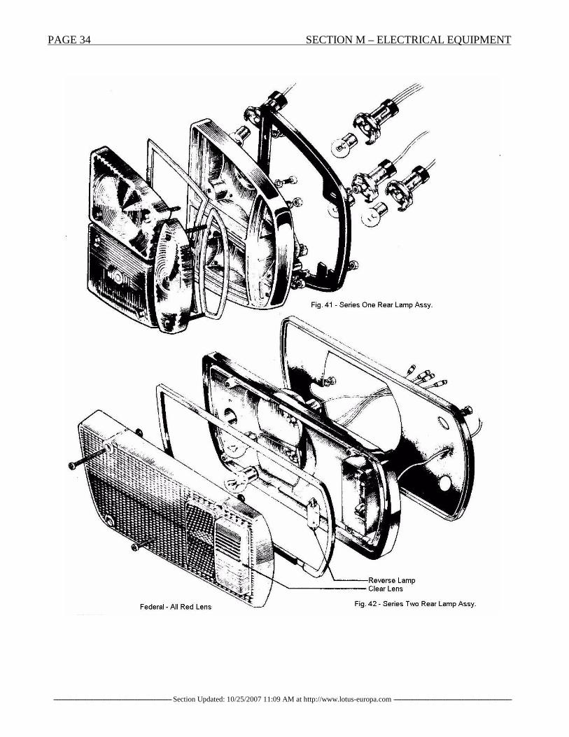
Rear Lamp Units.
Description.These units are mounted to the rear body panel and incorporate a stop/tail flasher, and reversing lamp.The unit consists of a die cast body with detachable lenses.Series One vehicles use rear lamp units of Carello manufacture in which each lens and bulb holder isseparately detachable. (See Fig. 41). [6]Series Two vehicles employ Lucas L 807 units, each cluster having a single piece detachable lenses,which embrace the various lamp compartments and includes reflectors (See Fig. 42). [6]
PAGE 34 SECTION M – ELECTRICAL EQUIPMENT
----------------------------------------------------------------------------------------Section Updated: 10/25/2007 11:09 AM at http://www.lotus-europa.com ----------------------------------------------------------------------------------------

SECTION M – ELECTRICAL EQUIPMENT PAGE 35
----------------------------------------------------------------------------------------Section Updated: 10/25/2007 11:09 AM at http://www.lotus-europa.com ----------------------------------------------------------------------------------------
Bulb Removal - Series One Vehicles.Reversing lamp.1. Remove the two cross-head screws retaining the clear lens in the rear lampcluster.2.Remove the bulb by pushing gently and turning anti (counter) clockwise.Bulb replacement Part No 382-12v.- 21w.
Stop/Tail Lamp.1. Remove the two cross-head screws retaining the red lens in the rear lamp cluster.2.Remove the bulb by pushing gently and turning anti (counter) clockwise.Bulb replacement: Part No 380 - 12v - 21/6w.
Rear Flasher Lamp.1. Remove the two cross-head screws retaining the amber lens in the rear lamp cluster.2.Remove the bulb by pushing gently and turning anti (counter) clockwise.Bulb replacement: Part No. 382 - 12v - 21w.
Bulb Removal - Series Two Vehicles.1. Remove the four cross-head screws securing the lens.2. The stop/tail and flasher bulbs are removed by pushing and turning anti (counter) clockwise. Thereverse lamp bulb is removed by pressing down on one end then lifting up and out.
Number Plate Lamp:Bulb Renewal.1. Remove the two screws retainingthe cover and lens.2. Push bulb contacts to one side andpull bulb from the contacts.3. Replace by pushing bulb intoposition, and refit cover, and lens.Do not forget to replace rubbersealing washer on screws.(Interposed between body and lensassemblies).Do not over-tighten screws.Bulb replacement: Part No.254 –12v – 6w.
Interior Lamp:Pull bulb holder and lens downwards. Replace bulband refit by pushing bulb holder and lens intoposition.Bulb replacement: Part No. 254 - 12v - 6w.

PAGE 36 SECTION M – ELECTRICAL EQUIPMENT
----------------------------------------------------------------------------------------Section Updated: 10/25/2007 11:09 AM at http://www.lotus-europa.com ----------------------------------------------------------------------------------------
Side Flasher Lamp:Bulb renewal.Remove the single screw retainingthe lens.
Replace bulb and refit lens, takingcare to insert the lip of the lens intobezel, before fitting screw.Do not over-tighten screw.Bulb replacement : Part No. 501 -12v- 21w.
Instrument Illumination:Bulb renewal.All instrument illumination bulbs are removed from the rear of the facia panel. The bulb holdersthemselves being a push flit into the rear of each instrument.Bulb replacement, Part No. 987 - 12v - 2.2w.
Warning lamps:Bulb renewal.All warning lamp bulbs are removed from the rear of the facia panel.Warning lamps fitted within instruments on Series One vehicles, have push fit lamp holders in the rearof the instruments themselves.Federal vehicles equipped with brake and hazard warning lamps mounted in the facia panel are similarlyaccessible from the rear.Bulb replacement, Part No. 987 - 12v - 2.2w.------------------------------------------------------------------------------------------------------------------------------------------------------------------------------------M.12 - DIRECTION INDICATOR SYSTEM.
Description.The correct operation of direction signals requires that the flasher filament in the lamp bulbs (dependingon the position of the switch) flash intermittently whether or not the headlamps, parking lamps, taillamps or stop lamps are 'on'.
A correctly operating direction signal will be indicated by a regular intermittent flashing of the warninglamp located on the facia panel.
If when the ignition switch is on and the direction indicator is operated, the warning lamp does not flashin the usual manner or remains unlit, first check that this is not due to filament failure in either the frontor rear on that side. This can be checked by turning the switch to the opposite side - if the warning lampnow flashes, the circuit is in order and bulb replacement is indicated. On the other hand, if the warninglamp still does not flash, inspect the indicator lamps If these are working normally, failure of thewarning lamp bulb is indicated.

SECTION M – ELECTRICAL EQUIPMENT PAGE 37
----------------------------------------------------------------------------------------Section Updated: 10/25/2007 11:09 AM at http://www.lotus-europa.com ----------------------------------------------------------------------------------------
If, however, the indicator lamps are not functioning, it will be necessary to proceed to check the wiringand flasher unit. The efficiency of the flasher unit may be readily checked by plugging in a known goodsubstitute. The inoperative flasher lamp bulbs should be checked for a burned-out filament. Where it isfound that neither lamp has a burned-out filament, the wiring between the defective lamp and indicatorswitch must be checked.If the direction signal is entirely inoperative, check the fuse (see wiring diagram) flasher unit and circuitfrom the fuse box up through the steering column switch in the order named.The flasher unit is located behind the facia panel below the face level vent on the driving side. Noservicing of the flasher is required; where this unit breaks down in service it should be renewed.
Operation.
The unit depends for its operation on an electro-magnet in conjunction with the linear expansion of apiece of wire, which becomes heated as current flows through it. The expanding and contracting of thewire controls the speed at which the armature carrying the moving contact will move, as a result of thepull exerted by the electro-magnet. The sequence of operations is as follows: As current flows fromterminal 'B' to terminal 'L' and the lamps via the resistance wire and electromagnet, the wire heats upand expands.This allows the armature carrying one ofthe contacts to be attracted at the polepiece of the electro-magnet closingcontacts (A) and full voltage is thenapplied to the lamps via the windings ofthe electromagnet. Contacts (B) are alsoclosed completing the pilot lamp circuit.While contacts (A) are closed theresistance wire is short circuited andcools off.The taut section of the resistance wirecontracts and pulls back the armature toopen contacts (A).The pilot lamp on the facia panel will not flash unless sufficient current to light the filaments in frontand rear flasher lamps is passing through the windings of the electro-magnet to close contacts (B). Theflashing pilot lamp therefore, gives the driver a clear indication that the direction signals are workingcorrectly.It will be noted that in order to maintain the desired rate of flashing the filaments of the front and rearlamps are 'pre-heated' via the resistance wire during 'out' period of the flash.------------------------------------------------------------------------------------------------------------------------------------------------------------------------------------M.13 - INSTRUMENTS.
Speedometer.To Remove and Replace.1. From behind the facia, pull out the warning lamp bulb holders (Series One vehicles).2. Release the knurled nut securing the drive cable to the instrument.Remove the trip control to the instrument.

PAGE 38 SECTION M – ELECTRICAL EQUIPMENT
----------------------------------------------------------------------------------------Section Updated: 10/25/2007 11:09 AM at http://www.lotus-europa.com ----------------------------------------------------------------------------------------

SECTION M – ELECTRICAL EQUIPMENT PAGE 39
----------------------------------------------------------------------------------------Section Updated: 10/25/2007 11:09 AM at http://www.lotus-europa.com ----------------------------------------------------------------------------------------
1. Ventilators. 17. Ignition/Starter Switch.2. Steering Wheel. 18. Window Lift Switches.3. Tachometer. 19. Heater Control Flaps.4. Ignition Warning Light. 20. Ashtray.5.Direction Indicator Warning Light. 21. Gearshift Lever.6. Main Beam Warning Light. 22. Choke Control.7. Speedometer. 23. Heater Control.8. De-mist Grille. 24. Accelerator Pedal.9. Side/Head Light Switch. 25. Brake Pedal.10. Ammeter. 26. Clutch Pedal.11. '2-speed' Windscreen Wiper/Washer Control. 27. Direction indicator Control.12. Oil Pressure Gauge. 28. Trip Reset.13. Radio. 29. Horn.14. Water Temperature Gauge. 30. Handbrake.15. Fuel Gauge. 31. Headlamp Dip Control.16. Heater/Boost Switch.

PAGE 40 SECTION M – ELECTRICAL EQUIPMENT
----------------------------------------------------------------------------------------Section Updated: 10/25/2007 11:09 AM at http://www.lotus-europa.com ----------------------------------------------------------------------------------------
3. Remove the knurled nuts securing the retaining straps and pull instrument out from front of facia.4. The speedometer driving cable is removed by releasing the lower end from the gearbox, then pullingout the inner cable from this end.5. Replacement is a reversal of the removal procedure.
2. Tachometer.To Remove and Replace.1. Disconnect the battery.2. Pull out the warning lamp bulb holders (Series One vehicles).3. Remove the knurled nuts securing the retaining straps and pull instrument out from front of facia.4. Note locations of cables before releasing.
3. Oil Pressure Gauge.To Remove and Replace.1. Disconnect the battery.2. Remove the knurled nut securing the instrument retaining strap. Pull instrument forward and removecables.3. When replacing, which is a reversal of the removal instructions, ensure that the gauge is fed with adirect 12-volt supply (non-stabilized).
4. Water Temperature Gauge.To Remove and Replace.1. Disconnect the battery.2. Remove the knurled nut securing the instrument retaining strap. Pull instrument forward and removecables.3. When replacing, which is a reversal of the removal procedure, ensure that the gauge is fed via thevoltage stabilizer.
5. Fuel Gauge.To Remove and Replace.The removal and replacement procedure will be found in Section 'L' (Fuel system) of this publication.
6. Ammeter.To Remove and Replace.1. Disconnect the battery.2. Release the valance from below the facia (see Section 'B').3. Remove the knurled nut securing the instrument retaining strap. Pull instrument forward and removecables.4. Replacement is a reversal of the removal procedure.
7. Ambient Temperature Gauge.To Remove and Replace.1. The gauge with its sender unit is connected by its capillary tube and as such, must be removed as anassembly.2. Remove the instrument assembly in a similar fashion to the previously mentioned instruments, afterremoving the facia valances (see Section 'B').

SECTION M – ELECTRICAL EQUIPMENT PAGE 41
----------------------------------------------------------------------------------------Section Updated: 10/25/2007 11:09 AM at http://www.lotus-europa.com ----------------------------------------------------------------------------------------
8. Voltage Stabilizer.
The purpose of this unit is to stabilize the voltage, which operates the fuel, water temperature and oilpressure gauges, since constant voltage is desirable to ensure correct readings of these instruments.The voltage stabilizer is mounted directly below the radio aperture and beneath the fuel and waterinstruments at the rear of the facia panel. The securing bracket MUST be set vertically.If it is suspected that the voltage stabilizer is faulty, the following procedure is recommended.1. Ensure that the cables are correctly connected to their respective terminals.2. Ensure that both the stabilizer and its condenser are correctly earthed via the speedometer mountingor fuel contents gauge (vehicles manufactured 3/69 onwards).3. Maximum permissible 'out-of-true' of the mounting bracket' is 10° in any direction.NOTE : If the stabilizer is faulty, it cannot be repaired so must be replaced. When testing instruments itis recommended that the Smiths Instrument Tester (36 M 6183) be used in all applications.------------------------------------------------------------------------------------------------------------------------------------------------------------------------------------M.14 - EARTHING (GROUNDING) OF COMPONENTS.
As the car body is constructed from glass-fibre-reinforced-plastic (G.F.R.P.) it is most important toensure that all earthing connections are correctly made.The main earths are formed by the body to chassis attachments at: -1. Centre body mountings (at bottom of facia).2. Rear chassis to body mountings.When re-making the earth connections, ensure that the bolt and washer are clean and free from corrosion.They should be lightly smeared with petroleum jelly or silicone grease.
1. Battery.
The lead to earth is through the right-hand chassis member via the water pipe mounting bracket. Thering end terminal of the lead is secured to the chassis by a nut and bolt and it is important to ensure thatthe bolt is threaded throughout its entire length (not shouldered), so that when tightening it can be pulledfully up.It is equally important to ensure that both battery posts terminals are tight, free from verdigris [7], andprotected with petroleum jelly or silicone grease.
2. Wiring Loom (Harness).
The main loom is earthed (BLACK) cables at the following locations: -1. Facia. The correct location is to the left-hand facia to chassis mounting bracket bolt.2. Rear. To the right-hand chassis immediately above the right hand engine support insulator.3. Instrument and Switches.
All of these components are earthed through the wiring loom, therefore it is essential that ALL earthcontacts are cleaned of foreign matter or paint BEFORE attaching earth cables.

PAGE 42 SECTION M – ELECTRICAL EQUIPMENT
----------------------------------------------------------------------------------------Section Updated: 10/25/2007 11:09 AM at http://www.lotus-europa.com ----------------------------------------------------------------------------------------
4. Earthing Straps.These are fitted at the following locations and it is essential that a GOOD earth exist BEFORE fitting.Remove ALL paint from around the fixing bolt hole.1. Engine to right-hand support insulator.2. Radio to frame (left-hand facia to chassis mounting bracket).3. Rear chassis forks (radio interference suppression kit).
M.15 - SWITCHES.1. Facia Switches.To Remove and Replace.Special Equipment:All switches, with the exception of the window operating switches, can be removed without removal ofthe facia panel, after first removing the securing nuts.The window operating switches are secured to the rear of the facia panel by screws.2. Horn Switch.To Remove and Replace.1. Disconnect the battery.2. Prise out the centre button from the hub of the steering wheel.3. Lift out the switch brush.4. Reverse these instructions when replacing.
3. Direction Indicators Switch.To Remove and Replace.1. Disconnect the battery.2. Remove the binnacle or escutcheons as appropriate.3. Slacken the upper steering column clamp4. Remove the harness cover screw; this is located at the lower end of the harness cover directly abovecolumn. Remove harness cover.5. Mark position of cables then release from their snap connectors.6. Remove switch retaining screws and withdraw switch and harness.7. Reverse these instructions when replacing.
4. Lighting Switch.To Remove and Replace.The removal procedure is as given under '3' Direction Indicators Switch.
5. Relays and Flashers.
To Remove and Replace.1. Disconnect the battery.2. Mark the position of cables, then remove.3. Release the securing fixings of the offending relay or flasher unit and remove.4. Replace by reversing these instructions.

SECTION M – ELECTRICAL EQUIPMENT PAGE 43
----------------------------------------------------------------------------------------Section Updated: 10/25/2007 11:09 AM at http://www.lotus-europa.com ----------------------------------------------------------------------------------------
Note Re: Radiator Fan Relay.Some early production cars were delivered with the radiator fan relay position on the inner wheelvalance at the side of the radiator. To avoid possible shorting between the relay terminals and theradiator casing, it is recommended that the fan relay be relocated ABOVE and BEHIND the radiator butstill on the inner wheel valance.
6. Ignition/Starter Switch.
To prevent the possibility of the ignition/starter switch turning in its location, it is recommended that alockplate be used as follows:1. Disconnect the battery.2. Using plate (Part No. 36 B 314), measure 1.5 in. (38 mm.) from the long side, which contains the 'D'-shaped hole. Cut plate at this dimension. Bend the four corners of the plate to form small tags, thesebeing at right-angles to the plate.3. Remove the nut from the reverse side of the facia panel, which secures the switch. Add the lockplatewith its turned-up corners TOWARDS the panel and replace the nut. As the nut is tightened, the cornerson the plate will be pulled into the panel, thus securing the plate and hence the switch.
7. Steering Lock.
A steering lock installation is approved for Series Two vehicles and should be wired as shown in theaccompanying illustration.
8. Reverse Switch.
A check should occasionally be made to ensure that mounting bolts securing the switch bracket to thegearbox are tight and that the switch itself is secure on the bracket. Early vehicles were fitted with a steelwasher beneath the mounting nut. In order to avoid the possibility of this shorting and causing blownfuses, the washer should be replaced by an insulating grommet (Part No. 36 B 6131).

PAGE 44 SECTION M – ELECTRICAL EQUIPMENT
----------------------------------------------------------------------------------------Section Updated: 10/25/2007 11:09 AM at http://www.lotus-europa.com ----------------------------------------------------------------------------------------
M.16 - MOTOR.FAN UNIT.
Description.Above a certain temperature the engine is cooled by a motor-fan unit, which is automatically switchedon and off to suit the engine temperature.This system consists of:- The motor-fan unit itself (electric motor fed with a 12-volt supply and driving a fan).-A relay mounted near the radiator feeds the current from the battery to the fan.- A MOSTA temperature switch, which automatically switches the fan on and off to suit the enginetemperature.
Temperature at which the contacts close: 82 (+1 .5/- 1)° C (179.6 (+2.7/-1.8)° F) [8]
Temperature at which the contacts open: 68 (+2/-1 .5)° C (154.4 (+3.6/-2.7)° F)
When the coolant temperature in the region of the 'MOSTA' switch reaches 68°C (154.4 F) the MOSTAswitch contacts open.When the coolant temperature in the region of the 'MOSTA' switch reaches 82°C (179.6°F) the MOSTAswitch contacts close, the relay coil is energized and its armature is moved over.The fan motor is fed with current and the fan rotates.The increase in the air circulation through the radiator and in the engine compartment reduces thecoolant temperature.When this temperature reaches: 68°c (154.4°F), the MOSTA temperature contacts open again, the relaycoil is no longer fed with current, the armature is released and the contacts open: the current supply tothe fan is switched off.

SECTION M – ELECTRICAL EQUIPMENT PAGE 45
----------------------------------------------------------------------------------------Section Updated: 10/25/2007 11:09 AM at http://www.lotus-europa.com ----------------------------------------------------------------------------------------
Removing and refitting the motor-fan unit:
Switch off the battery current.Mark the two leads which feed the motor fan unit sothat they are not connected to the wrong terminals whenrefitting.Disconnect the two clips, which feed the motor on thecontrol relay R.Remove the 4 bolts, which secure the fan to the radiator.
Dismantling the motor-fan unit.The motor-fan unit consists of 3 distinct parts:1. The electric motor, which drives the fan and itshousing.2. The fan.3. The protective fan casing.
Removing the fan:Unscrew nut (1), which secures the fan to its driveshaft.Remove the fan (2) forwards.
Warning: It is a left-hand thread.
Remove the fan support and protective casing:Unscrew and remove the screws, which fasten thesupport to the electric motor body and separatethese 2 parts.

PAGE 46 SECTION M – ELECTRICAL EQUIPMENT
----------------------------------------------------------------------------------------Section Updated: 10/25/2007 11:09 AM at http://www.lotus-europa.com ----------------------------------------------------------------------------------------
Replacing the fan-unit motor carbon brushes.Unscrew the two screws (6) and (7), which securethe rear end plate to the body.
Remove the end plate and pull back the brushcarrier plate (B).
To replace the brushes, unsolder the brush leads atsoldering points 9 & 10.
Checking the fan-unit:
1. Use a pilot light between terminal 5 on the relay and earth(ground).If the light does not switch on, check the lead, which connects the battery to terminal 5.If the light switches on, check the relay coil feed system.2. Connect the light between the + on the regulator and earth (ground).If the light does not switch on, check the connecting lead between the voltage regulator and the ignitionswitch.If the light switches on, check the lead, which connects the regulator to terminal (4).3. Connect the pilot light between terminal (4) and earth (ground).If the light does not switch on, recondition or replace the lead.If the light switches on, check the relay coil.4. Connect terminal 2 on the relay to earth (ground).If the relay does not work replace it.If the relay works and the motor-fan unit does not run.5. Connect pilot light between number 1 relay terminal and earth (ground).The relay coil is still to be energized.If the light does not switch on, replace the relay.If the light switches on, check:- the motor feed harness.- the motor itself.

SECTION M – ELECTRICAL EQUIPMENT PAGE 47
----------------------------------------------------------------------------------------Section Updated: 10/25/2007 11:09 AM at http://www.lotus-europa.com ----------------------------------------------------------------------------------------
If the motor runs correctly, check the earthing (grounding circuit) for the relay coil (MOSTAtemperature switch).6. Remove the lead which connects terminal 2 on the relay to earth (ground) and short-circuit the 2terminals on the MOSTA temperature switch by means of a lead.If the motor turns, replace the MOSTA temperature switch.If the motor does not turn, check the leads connecting:- terminal 2 on the relay to the MOSTA temperature switch.- the MOSTA temperature switch to terminal 3 on the relay.- Check the relay earth (ground) - (terminal 3).
Checking the MOSTA temperature switch:
The switch should make contact at a temperature T of 82 (+ 1.5/-1)° C (179.6 (+ 2.7/-1.8)° F)
The switch should open at a temperature: T of 68 (+ 2/- 1.5)° C (154.4 (+3.6/- 2.7)° F)
The difference between the temperature at which the contact open and the temperature at which thecontacts close should always be greater than 6° C (11° F) and less than 20° C (36° F).
Checking:- Connect a 0.1 amp pilot light between the (÷) terminal of a battery and one of the terminals of thetemperature switch.- Connect the other terminal of the temperature switch to the (-) terminal of the battery.- The light should not switch on.- Immerse the lower part of the temperature switch in water which has been raised to a temperature:T + 0.5° C (84° C) (183.2° F)Before a period of five minutes has elapsed the light should switch on.- Pour cold water into the tank (whilst keeping the water moving in order to obtain a uniformtemperature at all points in the tank.When the temperature of the water has fallen to T - 0.5° C (66° C) (150.8° F) the light should switch out.

PAGE 48 SECTION M – ELECTRICAL EQUIPMENT
----------------------------------------------------------------------------------------Section Updated: 10/25/2007 11:09 AM at http://www.lotus-europa.com ----------------------------------------------------------------------------------------
M.17 - ALTERNATOR.
Description.A 12-volt S.E.V Motorola alternator, type A 12/30 is fitted to the vehicle.The nominal output at 30 amps at a constant 3,000 r.p.m when warm is 13.2 volts. The field coilresistance is 5.2 +/- 0.2 ohms [9] at a temperature of 25°C measured across the slip rings.The unit is robustly constructed and will require very little maintenance in service, as there is nocommutator and lubrication is not required.
To remove:Disconnect the battery.Disconnect the 3 alternator leads:- + terminal.- field terminal (EXC)- earth (ground) terminal (M).
Unscrew and remove bolt (A) (which is used toadjust the belt tension) on the tensioner.- Unscrew bolt B which secures the alternator tothe cylinder block.- Remove the belt.
To Replace:Replacement is a reversal of the procedure outlined above.
Alternator main feed.The alternator main feed cables should be securely attached to the outlet pipe of the fuel pump usingsuitable heavy duty tape.

SECTION M – ELECTRICAL EQUIPMENT PAGE 49
----------------------------------------------------------------------------------------Section Updated: 10/25/2007 11:09 AM at http://www.lotus-europa.com ----------------------------------------------------------------------------------------
Checking and adjusting the belt tension:
1. Checking principle.The belt tension is checked by measuring itsdeflection under a load of 3 m.da N (6 lb 13 ounces).This check is carried out by special tool Part No.46M6206.
2. Description of tool.The tool consists of:- A bar (1), which rests across the belt, over the twopulley centres.- A plunger (2), which slides in the bar and permitsload to be applied to the belt.- The plunger body contains a rated spring, which rests on the sliding component (3).- The sliding component is graduated in millimeters and gives a belt deflection reading.- A rubber ring (4) is fitted round the sliding component.- This ring permits one to read the belt deflection after removing the tool from the belt in cases wherethe belt is in a position to which access is difficult and from which a direct reading cannot be obtained.
3. Use of the tool. [12]Press the bar against the belt with the plungerapproximately half-way between the pulleys.
- Press on the plunger until the shoulder (5) on thesliding part makes contact with the shoulder body.In this position the load of 3 m.da. N is being
applied to the belt. At this point:- Take the belt deflection reading from the top edge of the bar, and compare this reading with the figuregiven in the following list.Adjusting figures.Deflection under a load of 3 m.da N (6 lb 3 ounces)On fitting: 7 to 9.5 mm (9/32 to 3/8") After 2000 kms (1200 miles): 7 to 9.5 mm (9/32 to 3/8").
NOTE - The maximum permissible deflection is 13 mm (33/64").When the deflection is greater than this, re-tension the belt.

PAGE 50 SECTION M – ELECTRICAL EQUIPMENT
----------------------------------------------------------------------------------------Section Updated: 10/25/2007 11:09 AM at http://www.lotus-europa.com ----------------------------------------------------------------------------------------

SECTION M – ELECTRICAL EQUIPMENT PAGE 51
----------------------------------------------------------------------------------------Section Updated: 10/25/2007 11:09 AM at http://www.lotus-europa.com ----------------------------------------------------------------------------------------
ADDITIONAL INFORMATION
M.18 - VOLTAGE STABILIZER
Commencing at Chassis No. 1530, a new voltage stabilizer (Part No. 50 M 6096) has been fittedwhich is provided with a separate earth terminal, this being directly connected to the earth cable withinthe wiring loom (harness).
When using the stabilizer as a replacement on earlier cars, fit a 'Lucar' terminal in the place of the ringterminal in order to ensure adequate earthing.
M.19 - IGNITION COIL
Commencing at Chassis No. 0169, the ignition coil is mounted on the front face of the R/H wheelarch.
All coils should be mounted in this position irrespective of where they were originally mounted.
M.20 - CABLE COLOUR CODING
A new system of cable colours has been recently introduced in that cable manufacturers willproduce plain colours only and striping of cables will be done by loom manufacturers to suit their ownneeds. Since it is cheaper, only white cables will in future be striped and these will be distinguishedsolely by their stripes.
Two BLUE stripes and one RED stripe on a white base denotes BLUE/RED (see Fig. 67). In theold system this would be denoted by a BLUE ground with a RED stripe.
Two stripes of the same colour denote the base colour and a single stripe denotes the trace colour.Twist the cables to check the stripes, as the natural helix does not make for easy recognition
Two BLUE stripes on a white base denotes BLUE/WHITE. This is equivalent to two BLUEstripes and a WHITE stripe on a WHITE base (see Fig. 68).
In the old system, this would be BLUE cable with a WHITE stripe. TAKE CARE NOT to confuse,for example, the old type WHITE/BLUE (white cable with a single blue stripe) with the new colourcoding.
Plain (self) coloured cables will still continue to be used and both systems (old and new) mayoccur in the same loom.

PAGE 52 SECTION M – ELECTRICAL EQUIPMENT
----------------------------------------------------------------------------------------Section Updated: 10/25/2007 11:09 AM at http://www.lotus-europa.com ----------------------------------------------------------------------------------------
M.21 – REVERSE LAMP SWITCH
Where difficulty is experienced in switching off the reverse lamps it will be found that this iscaused by the operating plunger of the switch over-traveling, thus holding the plunger in the 'on' position.To adjust the switch, the following procedure is recommended:1. With the engine 'dead', select reverse gear, with ignition 'on'.2. With the reverse lamps 'on', bend the actuating bracket of the switch on the gearshift cross-lever,away from the switch plunger until the lamp switches 'off'.3. Bend the bracket back again by 1/8 in. (3.2 mm) so that the lamp is just switched 'on'. Afteradjustment, crank the bracket so that the part, which is in contact with the switch plunger, is vertical tothe plunger.4. With a second operator moving the gearshift lever, check the operation of the switch.5. Finally, apply a liberal coating of silicone grease to the switch and plunger to prevent the ingress ofwater.
M.22 - RADIO
Receiver
A radio can be fitted as an accessory in the following manner from Chassis No. 54/0645(commencement of Series 2 models).1. Disconnect the battery.2. Remove the radio aperture blanking piece from the facia panel.3. From the front of the receiver, pull off the control knobs. Remove the nuts now revealed and removethe tuning scale. Locate the speaker lead from behind the facia and connect to receiver. Connect theaerial jumper cable and battery cable inserting the fuse in the latter. Insert the receiver into the aperturein the facia panel and push back sufficiently to enable the side mounting brackets to be fitted. Thebrackets and fittings are contained in 'package 5' of the 'Fitting and Suppression kit'. Connect the earthbraid from 'package 4' to the L/H bracket.4. Move the radio forward so that the front protrudes from the facia panel. Place the chromed bezel fromthe 'Fitting and Suppression kit' over the front, replace the tuning scale, nuts and control knobs. Connectbattery cable to terminal '4' on the ignition switch.
Speaker
1. Remove the trim panel from the door, L/H or R/H, whichever is preferred (see Section 'B').2. At the lower front corner of the reverse side of the panel is a cut-out. Cut the trim to the same shape asthe cut-out. Using the speaker grille as a template, mark the four mounting stud holes, drill the holes,mount the grille in the trim panel from the front. From the reverse side of the trim panel, mount thespeaker

SECTION M – ELECTRICAL EQUIPMENT PAGE 53
----------------------------------------------------------------------------------------Section Updated: 10/25/2007 11:09 AM at http://www.lotus-europa.com ----------------------------------------------------------------------------------------

PAGE 54 SECTION M – ELECTRICAL EQUIPMENT
----------------------------------------------------------------------------------------Section Updated: 10/25/2007 11:09 AM at http://www.lotus-europa.com ----------------------------------------------------------------------------------------
on the grille studs and secure assembly with the plain washers, spring washers and nuts from 'packageL.7'. Connect the speaker to the leads in the door and replace trim panel.
Aerial
1. Pull back the trim and felt from the inside of the L/H front corner of the driving compartment.2. Cut a 7/16 in. (11.11 mm) hole in the L/H front wing in such a position that the aerial tube will comejust inside the car interior and not into the wheelarch. Mount the aerial, fixing one end of the aerial braidfrom 'package No.4' of the 'Fitting and Suppression kit' to the earthing bracket on aerial, whilst the otherend of the braid is fitted as described under 'Package No.4' in Section 'M.23'.3. The aerial is mounted with its fixings in the following order:aerial with keyed washer, shakeproof washer, earth bracket, earth braid, car body, grommet, insulator,insulator cap, cap nut.
M.23 - RADIO SUPPRESSION
To give an acceptable reception from the radio, outside interference must be suppressed. This isachieved in the following manner:
General
1. Ensure that all metal to metal connections are clean and tight to give good electrical contact.2. The various items of the 'Fitting and Suppression kit' (Part No. 54 M 6048) are supplied in five smallpackages, mention of which has been made of some of them in Section 'M.22', in addition to the twoengine screening plates (Part No. 54 M 0110 and 54 M 0111). The items in each package will be dealtwith separately.
Screening Plates
1. Elongate the mounting holes on the upper plate (Part No. 54 M 0110) and scrape the paint fromaround the three holes in the flange of the plate. Remove the nut from the bolt on each hinge, which willcorrespond with the hole and the screws along the inner edge of the engine compartment grilles.2. Fix the plate to the engine compartment lid by replacing the fixings.3. Move the seats as far forward as possible and remove the rear trim panel (see Section 'B').4. Hold the bulkhead screening plate (Part No. 54 N 0111) in position, making certain it is not touchingthe wiring loom or fuel feed pipe, which pass across the engine compartment at the bottom of thebulkhead. Drill ¼ in. (6.35 mm) holes through the bulkhead using the plate as a template.5. Scrape the paint from around all holes and mount the plate using bolts passed through from front.
Package No. l
Remove the ignition coil from its mounting. Scrape the paint from the mounting area, replace thebracket fixing the clip of the 'l mfd' condenser and one end of the PVC covered earth braid under one ofthe mounting bolts. Connect the condenser cable to the 'SW (BAT)' terminal on the coil. Secure one endof each of the two remaining earth braids, to each of the lower bulkhead screening plates mounting bolts.Drill two ¼ in. (6.35 mm) holes in the chassis immediately below, scrape the paint and underseal awayand secure these braids to the chassis with the nuts and bolts, the nuts being fitted from below thechassis.

SECTION M – ELECTRICAL EQUIPMENT PAGE 55
----------------------------------------------------------------------------------------Section Updated: 10/25/2007 11:09 AM at http://www.lotus-europa.com ----------------------------------------------------------------------------------------
Package No. 2
Remove the sparking plug cables and fit the suppressors, Cut the HT lead from coil to distributorand fit the '15 ohm' in-line suppressor. Fit the two '1 mfd' condensers to the alternator earth terminal bytheir body clips and connect their cables to the main alternator terminal (BROWN cable). Fit the'.25mfd' condenser to a suitable bolt on the engine, near to the oil pressure sender unit and connect itscable to the sender unit.
Package No. 3
Fit the three similar earth braids to connect the two engine screening plates, using nuts and boltsin the three holes in the flange of each plate. Fit the other two braids, one between the centre hole in thebulkhead screening plate flange and the rear rocker cover bolt, the other between the air cleaner clampand a rocker cover bolt.
Package No. 4
Fit the 11 in. (28 cm.) long earth braid From a radiator fan mounting bolt to the chassis mountbolt below. Fit the 15 in. (38 cm.) long earth braid from a heater mounting bolt to the chassis mountingbolt below. Connect the aerial earth braid to the bolt on the end of the wiper motor and to the bottomL/H corner of the heater, by removing the screw at that point and replacing it by a longer one withwasher. Finally, connect the end of this braid to earth using one of the screws retaining the throttle cablebracket to the tunnel side. The radio earth braid should also be connected to earth at this point.
Package No. 5
Cut the RED/LIGHT GREEN and BLUE/LIGHT GREEN cables to the wiper motor and fit two-way 'bullet' connectors so that the '1 mfd' capacitor can be plugged in between these cables. Remove thetrim panel from the door. Fit two '1 mfd' capacitors, one between each of the feed cables to the windowmotor and the earth screw in the door. Suppression of the window motor in the R/H door is notnecessary, due to its distance from the aerial. Locate the '10 volt' stabilizer behind the facia panel. Fittwo 'l mfd' capacitors, one between each of the '1' and 'B' terminals and earth. Fit the '200MH' choke in-line from the 'l' terminal to the instruments. Note that two types of voltage stabilizers have been used;the early unit had a body earth, whilst the latter type is provided with a terminal earth.

PAGE 56 SECTION M – ELECTRICAL EQUIPMENT
----------------------------------------------------------------------------------------Section Updated: 10/25/2007 11:09 AM at http://www.lotus-europa.com ----------------------------------------------------------------------------------------
M.24 - REVERSE LAMP SWITCH
An improved reverse lamp switch is now fitted in current production and is available for fittingto existing cars if desired.
1. Disconnect the battery. Release the cable from the existing switch and remove switch.2. Remove the plug (just to the rear of the right-hand drive shaft) in the side of the gearbox casing anddiscard.3. Screw in the new reverse lamp switch (Part No. A065 M 6002) (see Fig. 111 in Section 'F' forlocation). Attach extension cable (Part No. A054 M 0165) to existing cable and to switch. Reconnect thebattery.
Editors Notes:[1] Page 9: Original text referenced Fig. 4. Corrected to Fig. 5 [JJ][2] Page 9: Original text referenced Fig. 5. Corrected to Fig. 6 [JJ][3] Page 12: Original text referenced Fig. 11. Corrected to Fig. 12 [JJ][4] Page 20: Original text reads (anti-clockwise). This is incorrect. The distributor rotates clockwisewhen viewed from above. [JJ][5] Page 23: Original text reads (at the end of Section). Corrected to (at the end of this Section). [JJ][6] Page 33: Original text referenced Fig. 40 upper and lower. Corrected to Fig. 41 and Fig. 42.
Series 1 vehicles starting at chassis number 460542 used Series 2 rear lamp assemblies. [JJ][7] Page 41: Verdigris is the common name for copper acetate. It's that green stuff that surrounds yourbattery posts. [JJ][8] Page 44: Removed phrase "92ºC +1.5". [JJ][9] Page 48: Added the phrase "+/-". [JJ][10] Page 14: Original text referenced "the above illustration". Corrected to Fig. 14 [JJ][11] Page 14: N.B.: An abbreviation for the Latin phrase 'nota bene', meaning 'note well.' It is used toemphasize an important point. [BB][12] Page 49: Added paragraph heading for clarity. [JJ][13] Page 11: Original text referenced Fig. 7. Corrected to Fig. 8 [JJ][14] Page 29: Original text referenced Fig. 34. Corrected to Fig. 35 [JJ][15] Page 32: Original text referenced Fig. 38. Corrected to Fig. 39 [JJ]


![DIRECTREC DR-2000 - Olympusresources.olympus-europa.com/imaging//Manuals/SS2012/DR-2000... · Troubleshooting ... button, then select [All Programs], [Olympus DSS Player Pro], [Dictation](https://static.fdocuments.in/doc/165x107/5b1f49ba7f8b9a397f8d06a9/directrec-dr-2000-troubleshooting-button-then-select-all-programs.jpg)