Electrical-Engineering-portal.com-Comparison of Neutral Earthing Methods
Upload
alaa-ramadanCategory
view
4download
1description
electrical-engineering-portal.com
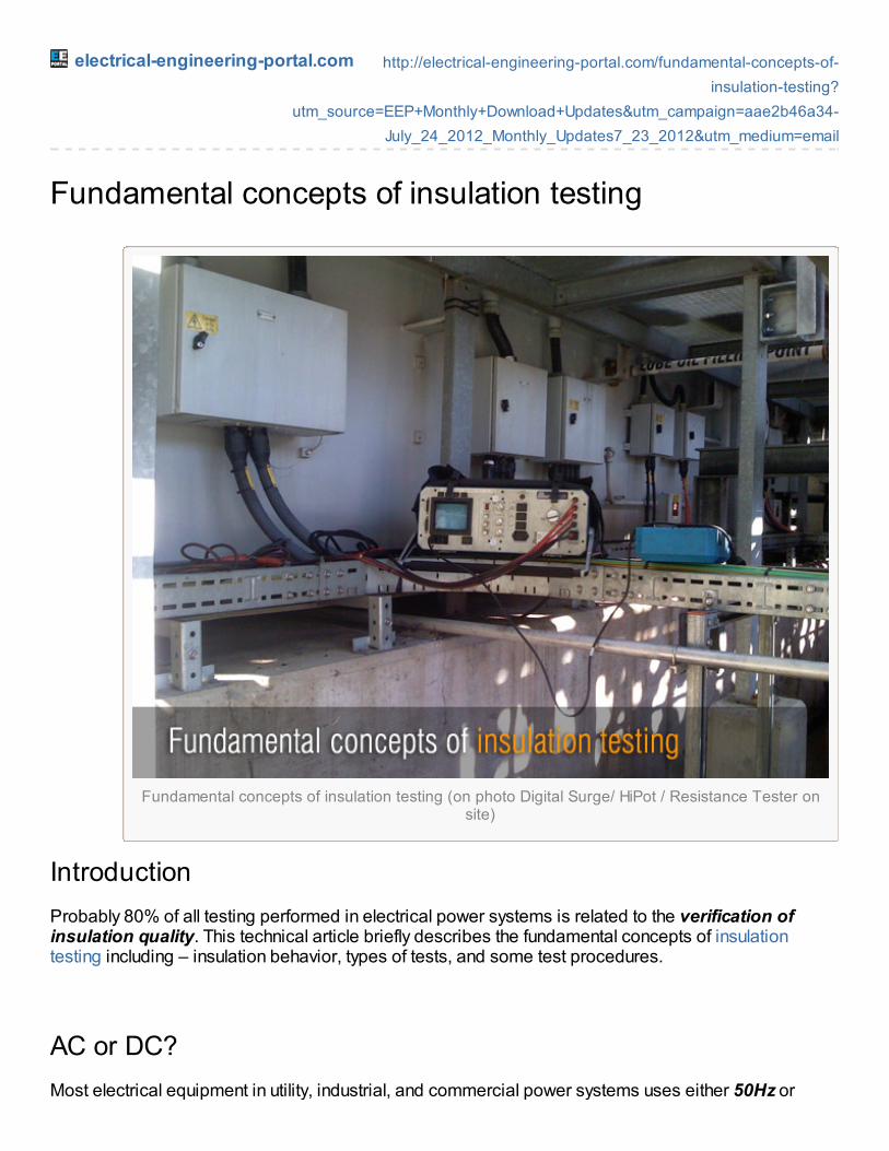
Fundamental concepts of insulation testing (on photo Digital Surge/ HiPot / Resistance Tester onsite)
http://electrical-engineering-portal.com/fundamental-concepts-of-insulation-testing?
utm_source=EEP+Monthly+Download+Updates&utm_campaign=aae2b46a34-July_24_2012_Monthly_Updates7_23_2012&utm_medium=email
Fundamental concepts of insulation testing
IntroductionProbably 80% of all testing performed in electrical power systems is related to the verification ofinsulation quality. This technical article briefly describes the fundamental concepts of insulationtesting including – insulation behavior, types of tests, and some test procedures.
AC or DC?Most electrical equipment in utility, industrial, and commercial power systems uses either 50Hz or
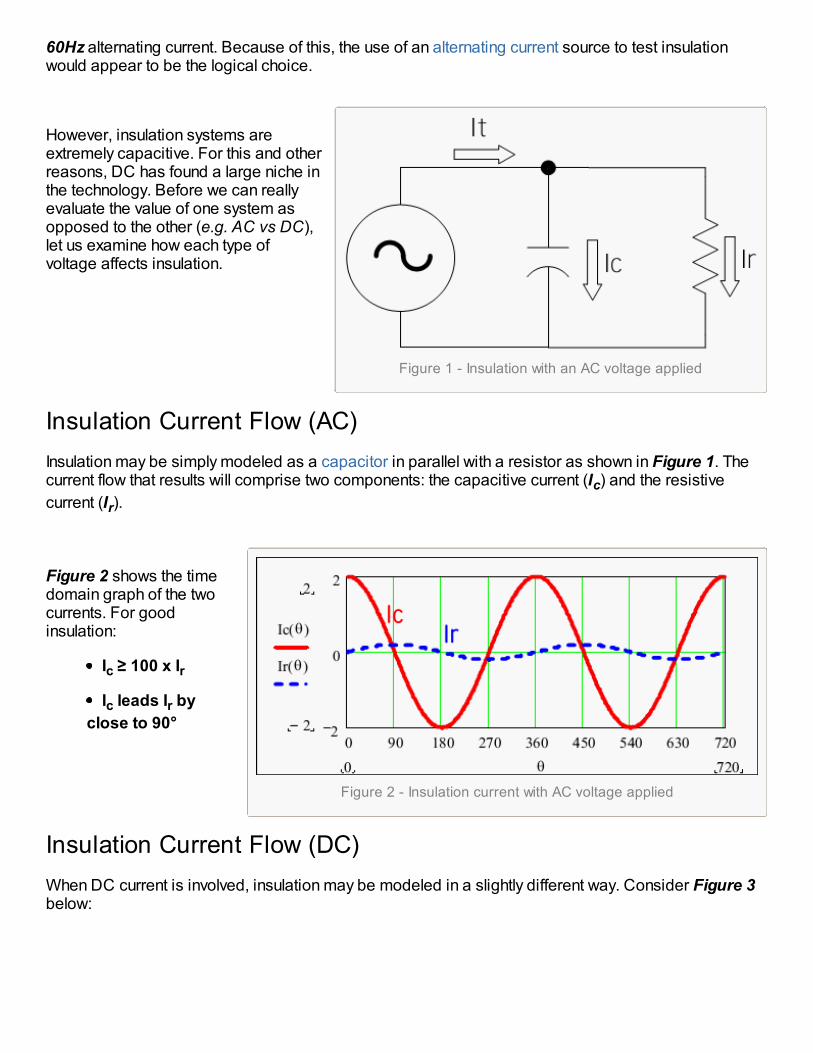
Figure 1 - Insulation with an AC voltage applied
Figure 2 - Insulation current with AC voltage applied
60Hz alternating current. Because of this, the use of an alternating current source to test insulationwould appear to be the logical choice.
However, insulation systems areextremely capacitive. For this and otherreasons, DC has found a large niche inthe technology. Before we can reallyevaluate the value of one system asopposed to the other (e.g. AC vs DC),let us examine how each type ofvoltage affects insulation.
Insulation Current Flow (AC)Insulation may be simply modeled as a capacitor in parallel with a resistor as shown in Figure 1. Thecurrent flow that results will comprise two components: the capacitive current (Ic) and the resistivecurrent (Ir).
Figure 2 shows the timedomain graph of the twocurrents. For goodinsulation:
Ic ≥ 100 x Ir
Ic leads Ir byclose to 90°
Insulation Current Flow (DC)When DC current is involved, insulation may be modeled in a slightly different way. Consider Figure 3below:
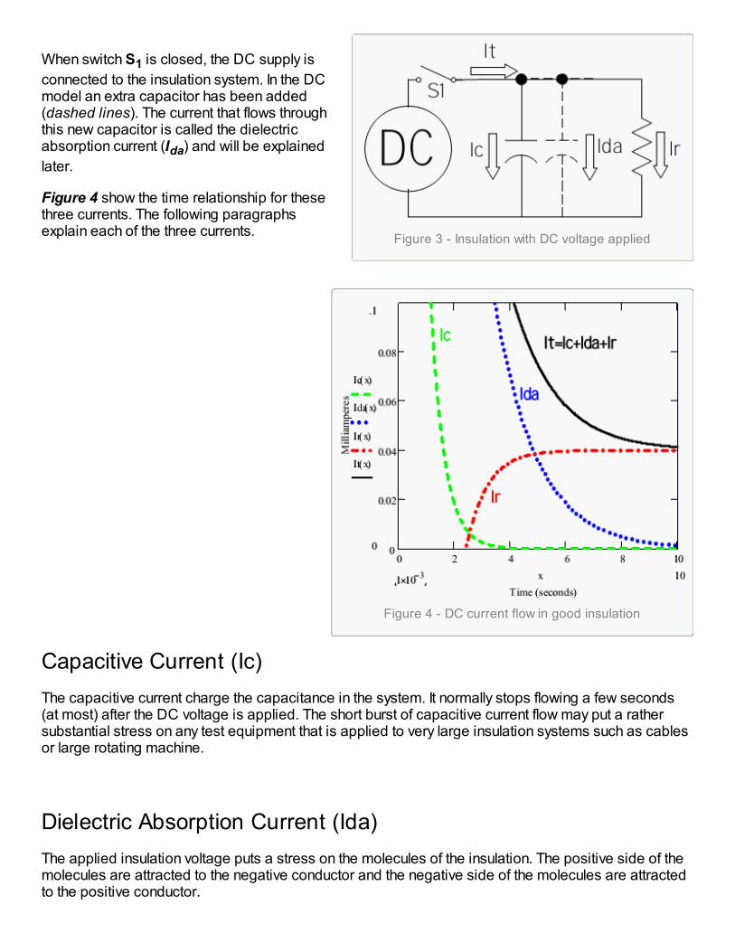
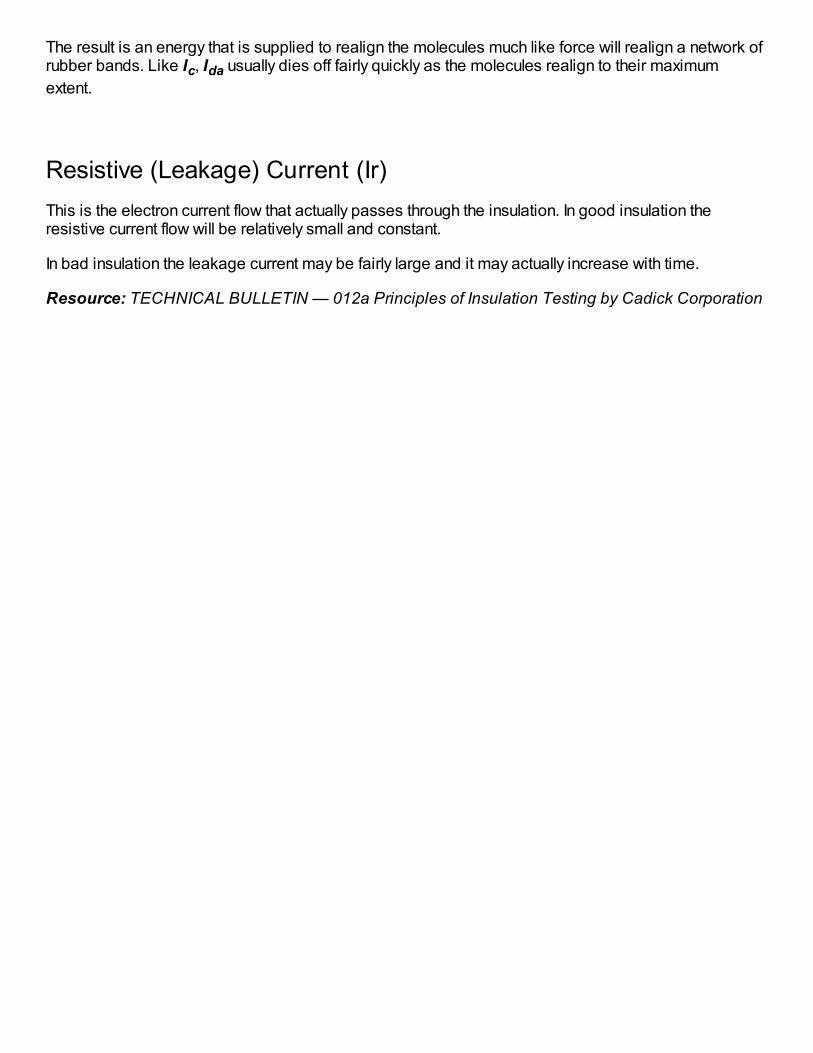
Figure 3 - Insulation with DC voltage applied
Figure 4 - DC current flow in good insulation
When switch S1 is closed, the DC supply isconnected to the insulation system. In the DCmodel an extra capacitor has been added(dashed lines). The current that flows throughthis new capacitor is called the dielectricabsorption current (Ida) and will be explainedlater.
Figure 4 show the time relationship for thesethree currents. The following paragraphsexplain each of the three currents.
Capacitive Current (Ic)The capacitive current charge the capacitance in the system. It normally stops flowing a few seconds(at most) after the DC voltage is applied. The short burst of capacitive current flow may put a rathersubstantial stress on any test equipment that is applied to very large insulation systems such as cablesor large rotating machine.
Dielectric Absorption Current (Ida)The applied insulation voltage puts a stress on the molecules of the insulation. The positive side of themolecules are attracted to the negative conductor and the negative side of the molecules are attractedto the positive conductor.
The result is an energy that is supplied to realign the molecules much like force will realign a network ofrubber bands. Like Ic, Ida usually dies off fairly quickly as the molecules realign to their maximumextent.
Resistive (Leakage) Current (Ir)This is the electron current flow that actually passes through the insulation. In good insulation theresistive current flow will be relatively small and constant.
In bad insulation the leakage current may be fairly large and it may actually increase with time.
Resource: TECHNICAL BULLETIN — 012a Principles of Insulation Testing by Cadick Corporation