Electrical Energy Systems - Erdinç Kuruoğlu · ... M.E. “Induction and Fractional Horsepower...
46
El-Hawary, M.E. “Induction and Fractional Horsepower Motors” Electrical Energy Systems. Series Ed. Leo Grigsby Boca Raton: CRC Press LLC, 2000
Transcript of Electrical Energy Systems - Erdinç Kuruoğlu · ... M.E. “Induction and Fractional Horsepower...

El-Hawary, M.E. “Induction and Fractional Horsepower Motors”Electrical Energy Systems.Series Ed. Leo GrigsbyBoca Raton: CRC Press LLC, 2000
185
© 2000 CRC Press LLC
Chapter 6
INDUCTION AND FRACTIONALHORSEPOWER MOTORS
6.1 INTRODUCTION
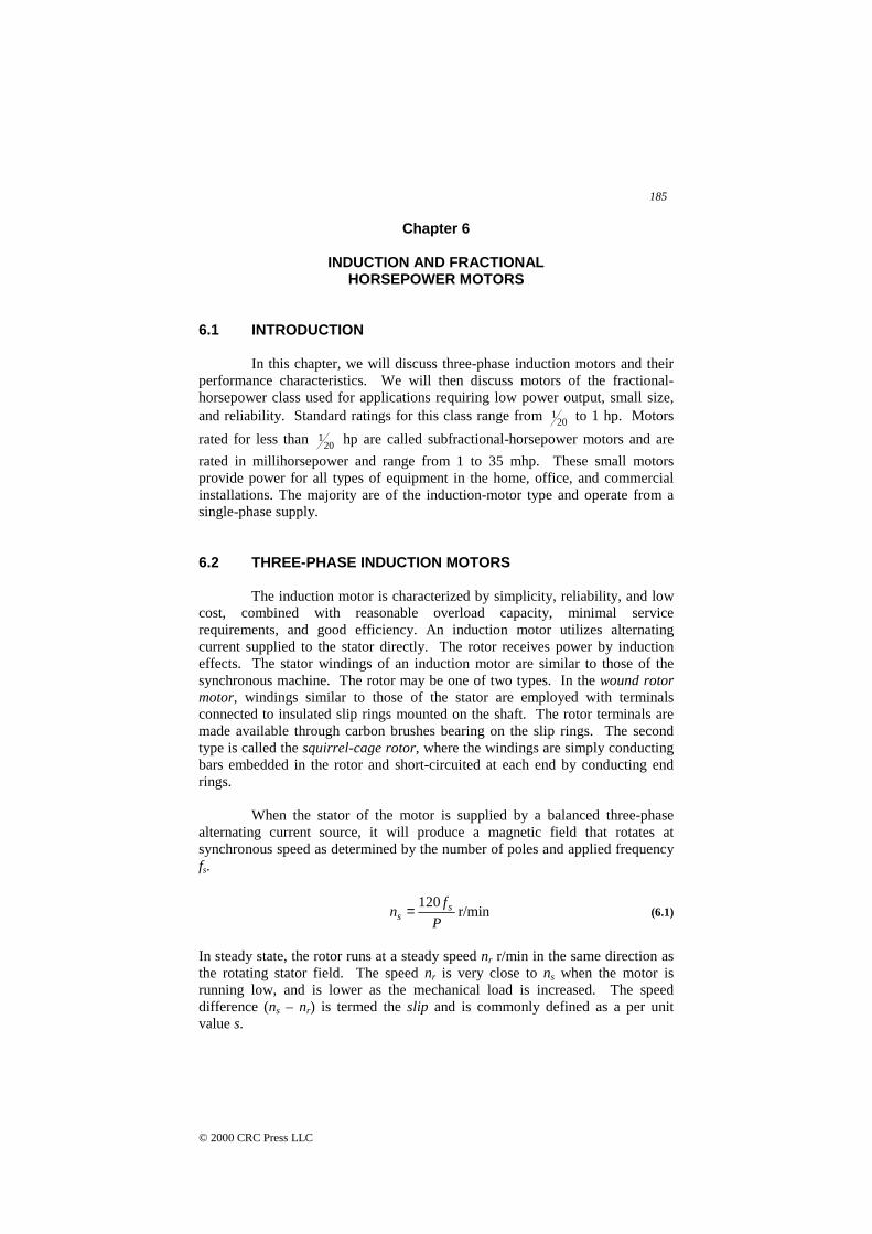
In this chapter, we will discuss three-phase induction motors and theirperformance characteristics. We will then discuss motors of the fractional-horsepower class used for applications requiring low power output, small size,and reliability. Standard ratings for this class range from 20
1 to 1 hp. Motors
rated for less than 201 hp are called subfractional-horsepower motors and are
rated in millihorsepower and range from 1 to 35 mhp. These small motorsprovide power for all types of equipment in the home, office, and commercialinstallations. The majority are of the induction-motor type and operate from asingle-phase supply.
6.2 THREE-PHASE INDUCTION MOTORS
The induction motor is characterized by simplicity, reliability, and lowcost, combined with reasonable overload capacity, minimal servicerequirements, and good efficiency. An induction motor utilizes alternatingcurrent supplied to the stator directly. The rotor receives power by inductioneffects. The stator windings of an induction motor are similar to those of thesynchronous machine. The rotor may be one of two types. In the wound rotormotor, windings similar to those of the stator are employed with terminalsconnected to insulated slip rings mounted on the shaft. The rotor terminals aremade available through carbon brushes bearing on the slip rings. The secondtype is called the squirrel-cage rotor, where the windings are simply conductingbars embedded in the rotor and short-circuited at each end by conducting endrings.
When the stator of the motor is supplied by a balanced three-phasealternating current source, it will produce a magnetic field that rotates atsynchronous speed as determined by the number of poles and applied frequencyfs.
r/min 120
P
fn s
s = (6.1)
In steady state, the rotor runs at a steady speed nr r/min in the same direction asthe rotating stator field. The speed nr is very close to ns when the motor isrunning low, and is lower as the mechanical load is increased. The speeddifference (ns – nr) is termed the slip and is commonly defined as a per unitvalue s.

186
© 2000 CRC Press LLC
s
rs
n
nns
−= (6.2)
Because of the relative motion between stator and rotor, induced voltages willappear in the rotor with a frequency fr called the slip frequency.
sr sff = (6.3)
From the above we observe that the induction motor is simply a transformer butthat it has a secondary frequency fr.
Example 6.1Determine the number of poles, the slip, and the frequency of the rotor currentsat rated load for three-phase, induction motors rated at:
A. 2200 V, 60 Hz, 588 r/min.B. 120V, 600 Hz, 873 r/min.
SolutionWe use P = 120f/n, to obtain P, using nr, the rotor speed given to obtain the slip.
A.
245.12588
60120 =×=P
But P should be an even number. Therefore, take P = 12. Hence
r/min 60012
60120120 =×==P
fns
The slip is thus given by
02.0600
588600 =−=−=s
rs
n
nns
The rotor frequency is
Hz 2.16002.0 =×== sr sff
B.
47.82873
600120 =×=P
Take P = 82.

187
© 2000 CRC Press LLC
Hz 6.3600006.0
006.0
r/min 05.87882
600120
=×==
=×=
r
s
f
s
n
Equivalent Circuits
An equivalent circuit of the three-phase induction motor can bedeveloped on the basis of the above considerations and transformer models.Looking into the stator terminals, the applied voltage Vs will supply the resistivedrop IsR1 as well as the inductive voltage jIsX1 and the counter EMF E1 where Is
is the stator current and R1 and X1 are the stator effective resistance andinductive reactance respectively. In a manner similar to that employed for theanalysis of the transformer, we model the magnetizing circuit by the shuntconductance Gc and inductive susceptance –jBm.
The rotor’s induced voltage E2s is related to the stator EMF E1 by
12 sEE s = (6.4)
This is due simply to the relative motion between stator and rotor. The rotorcurrent Irs is equal to the current Ir in the stator circuit. The induced EMF E2s
supplies the resistive voltage component IrR2 and inductive component jIr(sX2).R2 is the rotor resistance, and X2 is the rotor inductive reactance on the basis ofthe stator frequency.
)( 222 sXjIRIE rrs +=
or
)( 221 sXjIRIsE rr += (6.5)
From the above we conclude that the equivalent rotor impedance seen from thestator is given by:
221 jX
s
R
I
E
r
+=
The complete equivalent circuit of the induction motor is shown in Figure 6.1.
Considering the active power flow into the induction machine, we findthat the input power Ps supplies the stator I2R losses and the core losses. Theremaining power denoted by the air-gap power Pg is that transferred to the rotorcircuit. Part of the air-gap power is expended as rotor I2R losses with theremainder being the mechanical power delivered to the motor shaft. We canexpress the air-gap power as
188
© 2000 CRC Press LLC
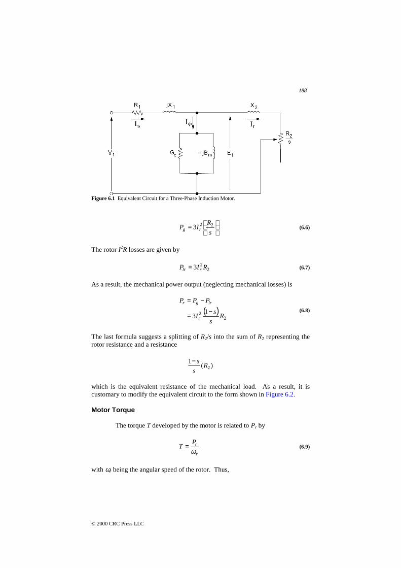
Figure 6.1 Equivalent Circuit for a Three-Phase Induction Motor.
=
s
RIP rg
223 (6.6)
The rotor I2R losses are given by
223 RIP rlr = (6.7)
As a result, the mechanical power output (neglecting mechanical losses) is
( )2
2 13 R
s
sI
PPP
r
lrgr
−=
−=(6.8)
The last formula suggests a splitting of R2/s into the sum of R2 representing therotor resistance and a resistance
)(1
2Rs
s−
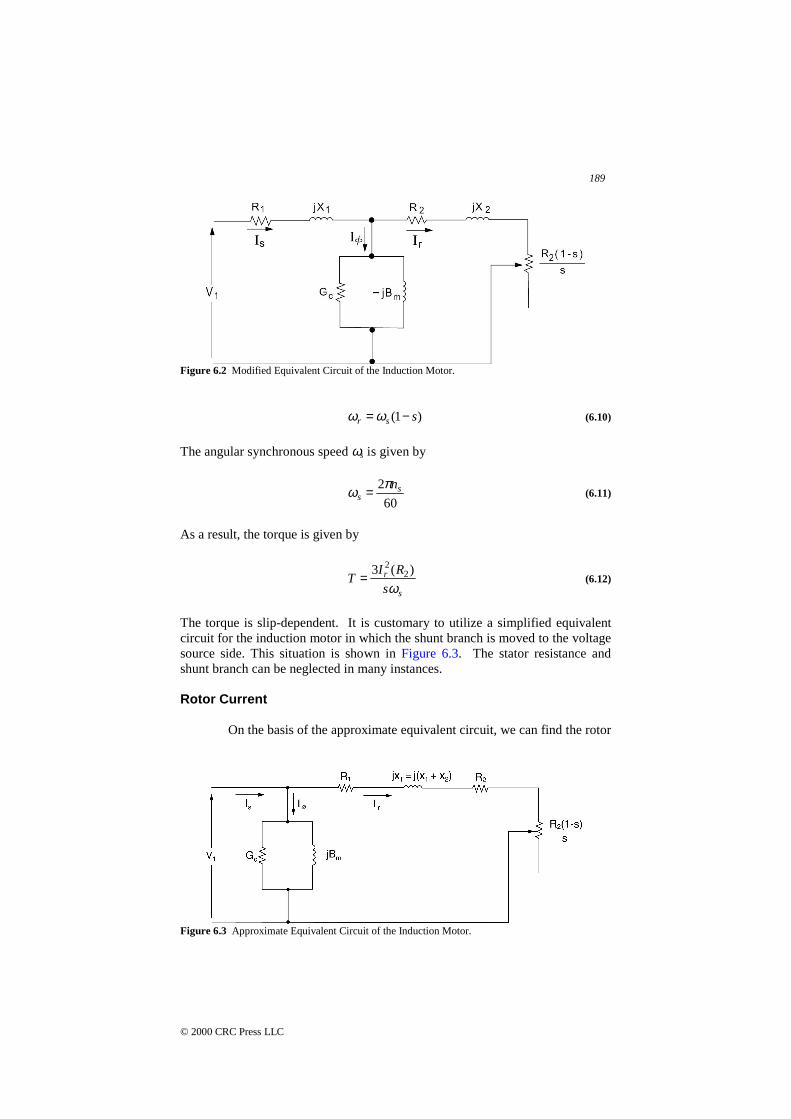
which is the equivalent resistance of the mechanical load. As a result, it iscustomary to modify the equivalent circuit to the form shown in Figure 6.2.
Motor Torque
The torque T developed by the motor is related to Pr by
r
rPT
ω= (6.9)
with ωr being the angular speed of the rotor. Thus,
189
© 2000 CRC Press LLC
Figure 6.2 Modified Equivalent Circuit of the Induction Motor.
)1( ssr −=ωω (6.10)
The angular synchronous speed ωs is given by
60
2 ss
nπω = (6.11)
As a result, the torque is given by
s
r
s
RIT
ω)(3 2
2
= (6.12)
The torque is slip-dependent. It is customary to utilize a simplified equivalentcircuit for the induction motor in which the shunt branch is moved to the voltagesource side. This situation is shown in Figure 6.3. The stator resistance andshunt branch can be neglected in many instances.
Rotor Current
On the basis of the approximate equivalent circuit, we can find the rotor
Figure 6.3 Approximate Equivalent Circuit of the Induction Motor.
190
© 2000 CRC Press LLC
current as
T
r
jXs
RR
VI
++=
21
1 (6.13)
At starting, we have ωr = 0; thus s = 1. The rotor starting current is hence givenby
Tr
jXRR
VI
st ++=
)( 21
1 (6.14)
The starting current in much higher than the normal (or full-load) current.Depending on the motor type, the starting current can be as high as six to seventimes the normal current.
Example 6.2A 15-hp, 220-V, three-phase, 60-Hz, six-pole, Y-connected induction motor hasthe following parameters per phase:
R1 = 0.15 ohmR2 = 0.1 ohmXT = 0.5 ohmGc = 6 × 10⁻³
Bm = 0.15 S
The rotational losses are equal to the stator hysteresis and eddy-current losses.For a slip of 3 percent, find the following:
A. the line current and power factor;B. the horsepower output;C. the starting torque.
SolutionA. The voltage specified is line-to-line value as usual. Utilizing the
approximate equivalent circuit of Figure 6.3, the rotor current canbe seen to be given by
A 17.809.36
5.003.0
1.015.0
3
220
!−∠=
+
+
=j
Ir
The no-load current Iφ is obtained as

191
© 2000 CRC Press LLC
( )A 05.197621.0
15.01063
220 3
j
jI
−=
−×= −φ
As a result, the line current (stator current) is
!535.33772.43 −∠=
+= φIII rs
Since V1 is taken as reference, we conclude that
8334.0cos
535.33
==
s
s
φφ !
B. The air-gap power is given by
W881.024,1303.0
1.0)09.36(33 222 =
=
=
s
RIP rg
The mechanical power to the shaft is
W135.634,12)1( =−= gm PsP
The core losses are
W4.290)(3 21 == cc GEP
The rotational losses are thus
W4.290=rlP
As a result, the net output mechanical power is
W735.343,12out
=−= rlm PPP
Therefore, in terms of horsepower, we get
hp 547.16746
735.343,12hpout ==
C. At starting, s = 1:
192
© 2000 CRC Press LLC
N.m. 25.12340
997.487,15
403
)60(2
W997.487,15)1.0()215.227(3
A 215.2275.0)1.015.0(
3
220
2
===
==
==
=++
=
πω
ππω
s
g
s
g
r
PT
P
jI
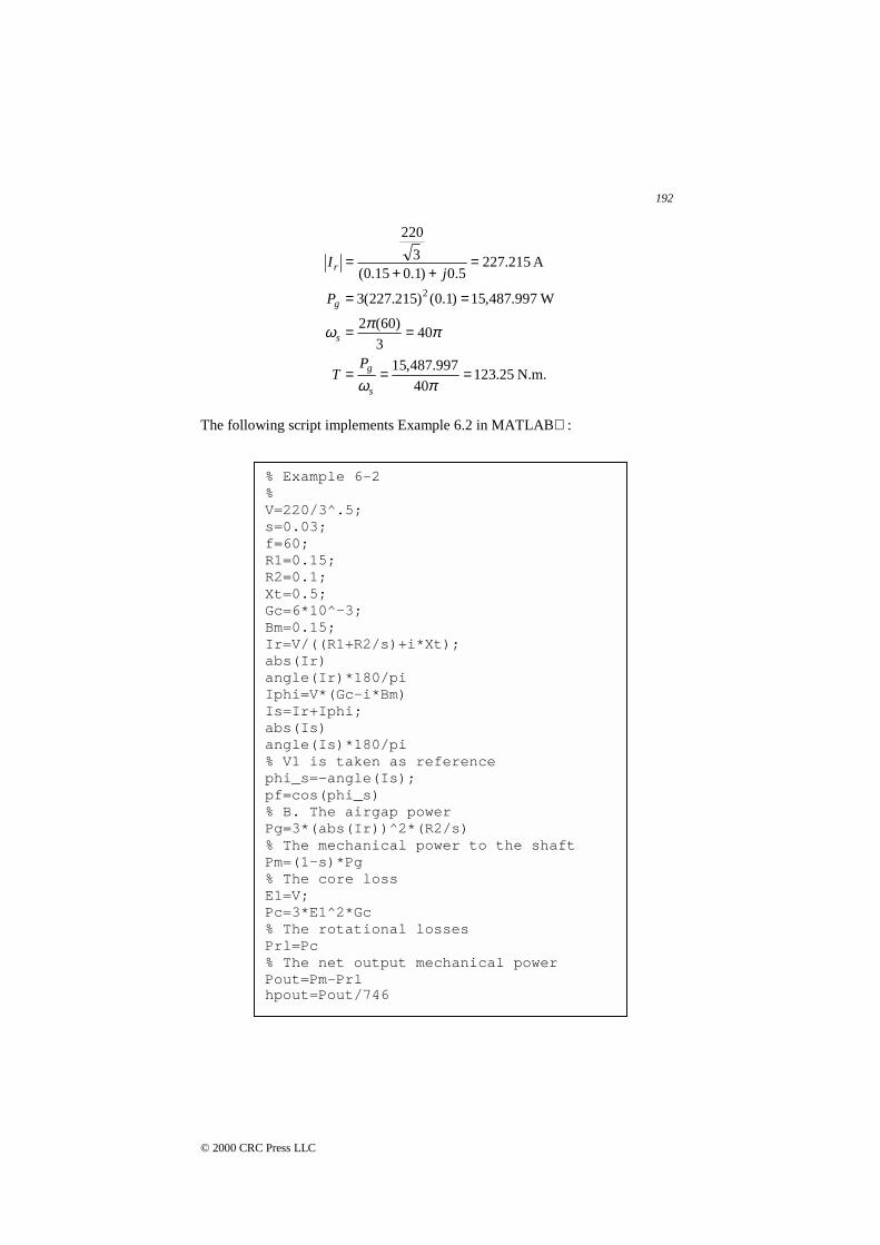
The following script implements Example 6.2 in MATLAB :
% Example 6-2%V=220/3^.5;s=0.03;f=60;R1=0.15;R2=0.1;Xt=0.5;Gc=6*10^-3;Bm=0.15;Ir=V/((R1+R2/s)+i*Xt);abs(Ir)angle(Ir)*180/piIphi=V*(Gc-i*Bm)Is=Ir+Iphi;abs(Is)angle(Is)*180/pi% V1 is taken as referencephi_s=-angle(Is);pf=cos(phi_s)% B. The airgap powerPg=3*(abs(Ir))^2*(R2/s)% The mechanical power to the shaftPm=(1-s)*Pg% The core lossE1=V;Pc=3*E1^2*Gc% The rotational lossesPrl=Pc% The net output mechanical powerPout=Pm-Prlhpout=Pout/746
193
© 2000 CRC Press LLC
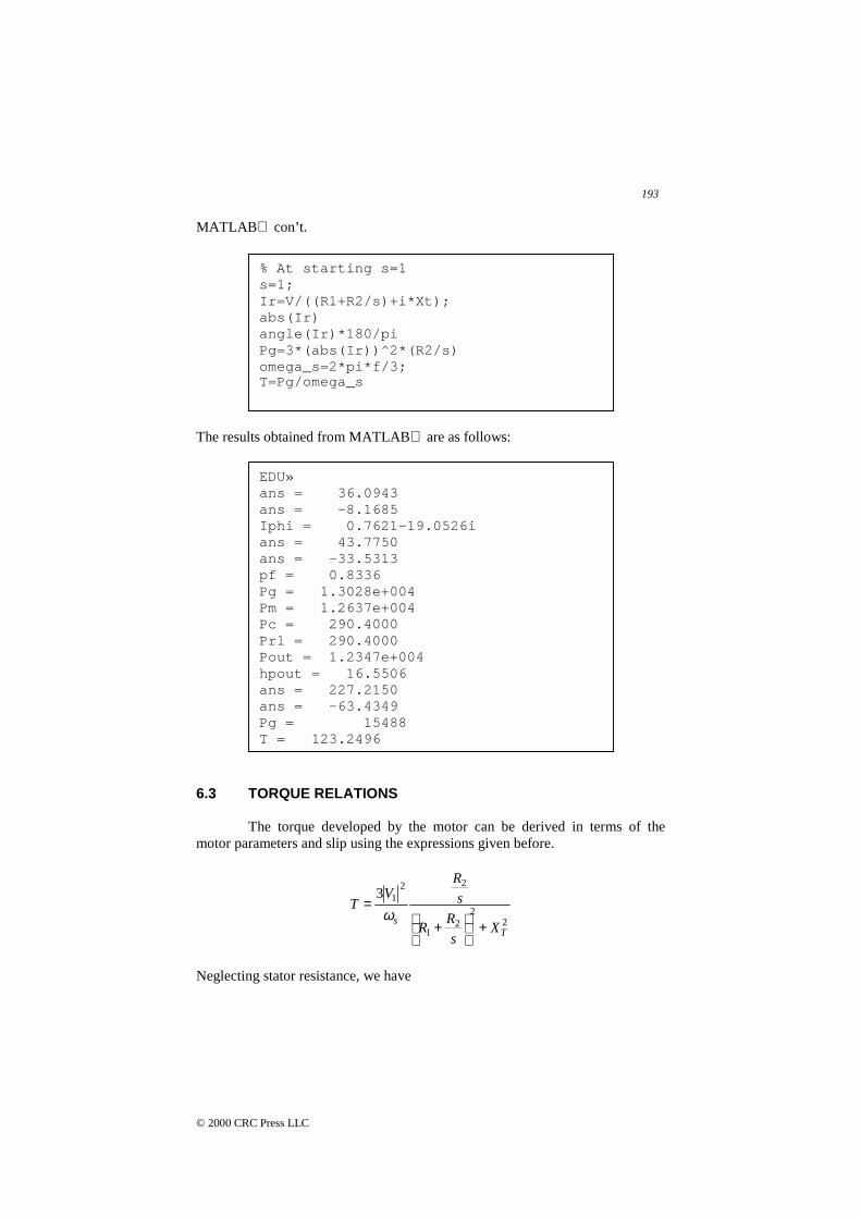
MATLAB con’t.
The results obtained from MATLAB are as follows:
6.3 TORQUE RELATIONS
The torque developed by the motor can be derived in terms of themotor parameters and slip using the expressions given before.
22
21
2213
Ts
Xs
RR
s
RV
T
+
+
=ω
Neglecting stator resistance, we have
% At starting s=1s=1;Ir=V/((R1+R2/s)+i*Xt);abs(Ir)angle(Ir)*180/piPg=3*(abs(Ir))^2*(R2/s)omega_s=2*pi*f/3;T=Pg/omega_s
EDU»ans = 36.0943ans = -8.1685Iphi = 0.7621-19.0526ians = 43.7750ans = -33.5313pf = 0.8336Pg = 1.3028e+004Pm = 1.2637e+004Pc = 290.4000Prl = 290.4000Pout = 1.2347e+004hpout = 16.5506ans = 227.2150ans = -63.4349Pg = 15488T = 123.2496
194
© 2000 CRC Press LLC
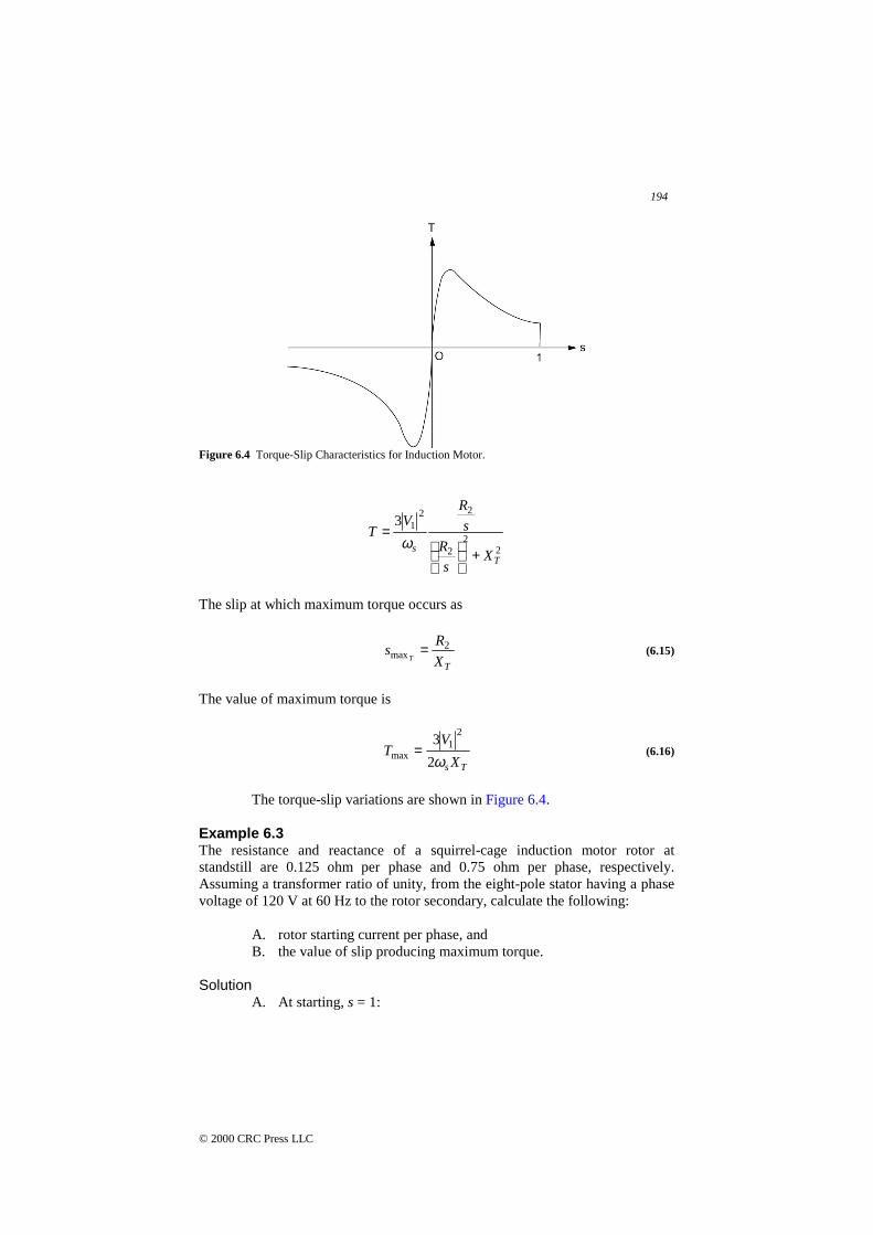
Figure 6.4 Torque-Slip Characteristics for Induction Motor.
22
2
2213
Ts
Xs
R
s
RV
T
+
=ω
The slip at which maximum torque occurs as
TX
Rs
T
2max = (6.15)
The value of maximum torque is
Ts X
VT
ω23
21
max = (6.16)
The torque-slip variations are shown in Figure 6.4.
Example 6.3The resistance and reactance of a squirrel-cage induction motor rotor atstandstill are 0.125 ohm per phase and 0.75 ohm per phase, respectively.Assuming a transformer ratio of unity, from the eight-pole stator having a phasevoltage of 120 V at 60 Hz to the rotor secondary, calculate the following:
A. rotor starting current per phase, andB. the value of slip producing maximum torque.
SolutionA. At starting, s = 1:
195
© 2000 CRC Press LLC
A 538.80823.157
75.0125.0
120
−∠=+
=j
Ir
B.
1667.075.0
125.0max ===
T
r
X
Rs
T
The following script implements Example 6.3 in MATLAB :
The results obtained from MATLAB are as follows:
Example 6.4The full-load slip of a squirrel-cage induction motor is 0.05, and the startingcurrent is five times the full-load current. Neglecting the stator core and copperlosses as well as the rotational losses, obtain:
A. the ratio of starting torque (st) to the full-load torque (fld), and
% Example 6-3% A squirrel cage induction motorRr=0.125; % ohmXT=0.75; % ohmV=120; % Voltf=60; % Hz% A. Rotor starting current per phase% At starting s=1Ir= V/(Rr+i*XT)abs(Ir)angle(Ir)*180/pi% B. The value of slip producingmaximum torques_maxT=Rr/XT
EDU»
Ir = 2.5946e+001 - 1.5568e+002I
ans = 157.8230
ans = -80.5377
s_maxT = 0.1667

196
© 2000 CRC Press LLC
B. the ratio of maximum (max) to full-load torque and thecorresponding slip.
Solutionsfld = 0.05 and Ist = 5Ifld
222
2
22
22
fld
st )5(05.0 =+
+
=
T
T
XR
XR
I
I
This gives
25.0375
242 ≅=TX
R
A.
( )
25.11
05.0)5(
3
2
st
fld2fld
2st
fld
st
22
==
=
=
s
s
I
I
T
T
s
RIT
s
r
ω
B.
( )
+=
+
=
+
=
=
==
2
1)5(
25.0
05.0
2
1
2
25.0
2
2
fld
max
max
fld
2
22
fld
2
max
fld
max
fld2fld
2max
fld
max
2max
s
s
s
s
X
Xs
R
s
s
s
s
I
I
T
T
X
Rs
T
T
T
T
T
T
T
T
Thus,

197
© 2000 CRC Press LLC
6.2fld
max =T
T
The following script implements Example 6.4 in MATLAB :
The results obtained from MATLAB are as follows:
% Example 6-4% A scuirrel cage induction motorsfld=0.05;sst=1;% Ist=5*Ifld;% ratio1=Ist/Ifld=5ratio1=5;%(ratio1)^2=((R2/sfld)^2+(XT)^2)/(R2^2+(XT)^2)% (R2/XT)^2*((1/sfld)^2-ratio1^2)=ratio1^2-1% ratio2=R2/XTf=[((1/sfld)^2-ratio1^2) 0 -(ratio1^2-1)]ratio2=roots(f);ratio2=ratio2(1)% A. T=3*Ir^2*R2/(sfld*ws)% ratio3=Tst/Tfldratio3=ratio1^2*(sfld/sst)% B.s_maxT=ratio2%Tmax/Tfld=(Imax/Ifld)^2*(sfld/s_maxT)%=(sfld/s_maxT)*((R2/sfld)^2+XT^2)/(2*XT^2)%(Tmax/Tfld)=(sfld/s_maxT)*((s_maxT/sfld)^2+1)/2% ratio4=Tmax/Tfldratio4=(sfld/s_maxT)*((s_maxT/sfld)^2+1)/2
EDU»f = 375 0 -24ratio2 = 0.2530ratio3 = 1.2500s_maxT = 0.2530ratio4 = 2.6286

198
© 2000 CRC Press LLC
6.4 CLASSIFICATION OF INDUCTION MOTORS
Integral-horsepower, three-phase, squirrel-cage motors are availablefrom manufacturers’ stock in a range of standard ratings up to 200 hp at standardfrequencies, voltages, and speeds. (Larger motors are regarded as special-purposed.) Several standard designs are available to meet various starting andrunning requirements. Representative torque-speed characteristics of fourdesigns are shown in Figure 6.5. These curves are typical of 1,800 r/min(synchronous-speed) motors in ratings from 7.5 to 200 hp.
The induction motor meets the requirements of substantially constant-speed drives. Many motor applications, however, require several speeds or acontinuously adjustable range of speeds. The synchronous speed of an inductionmotor can be changed by (1) changing the number of poles, (2) varying the rotorresistance, or (3) inserting voltages of the appropriate frequency in the rotorcircuits. A discussion of the details of speed control mechanisms is beyond thescope of this work. A common classification of induction motors is as follows.
Class A
Normal starting torque, normal starting current, low slip. This designhas a low-resistance, single-cage rotor. It provides good running performance atthe expense of starting. The full-load slip is low and the full-load efficiency ishigh. The maximum torque usually is over 200 percent of full-load torque andoccurs at a small slip (less than 20 percent). The starting torque at full voltage
Figure 6.5 Typical Torque-Speed Curves for 1,800 r/min General-Purpose Induction Motors.

199
© 2000 CRC Press LLC
varies form about 200 percent of full-load torque in small motors to about 100percent in large motors. The high starting current (500 to 800 percent of full-load current when started at rated voltage) is the disadvantage of this design.
Class B
Normal starting torque, low starting current, low slip. This design hasapproximately the same starting torque as the Class A with only 75 percent ofthe starting current. The full-load slip and efficiency are good (about the sameas for the Class A). However, it has a slightly decreased power factor and alower maximum torque (usually only slightly over 200 percent of full-loadtorque being obtainable). This is the commonest design in the 7.5 to 200-hprange of sizes used for constant-speed drives where starting-torque requirementsare not severe.
Class C
High starting torque, low starting current. This design has a higherstarting torque with low starting current but somewhat lower running efficiencyand higher slip than the Class A and Class B designs.
Class D
High starting torque, high slip. This design produces very high startingtorque at low starting current and high maximum torque at 50 to 100-percentslip, but runs at a high slip at full load (7 to 11 percent) and consequently haslow running efficiency.
6.5 ROTATING MAGENTIC FIELDS IN SINGLE-PHASEINDUCTION MOTORS
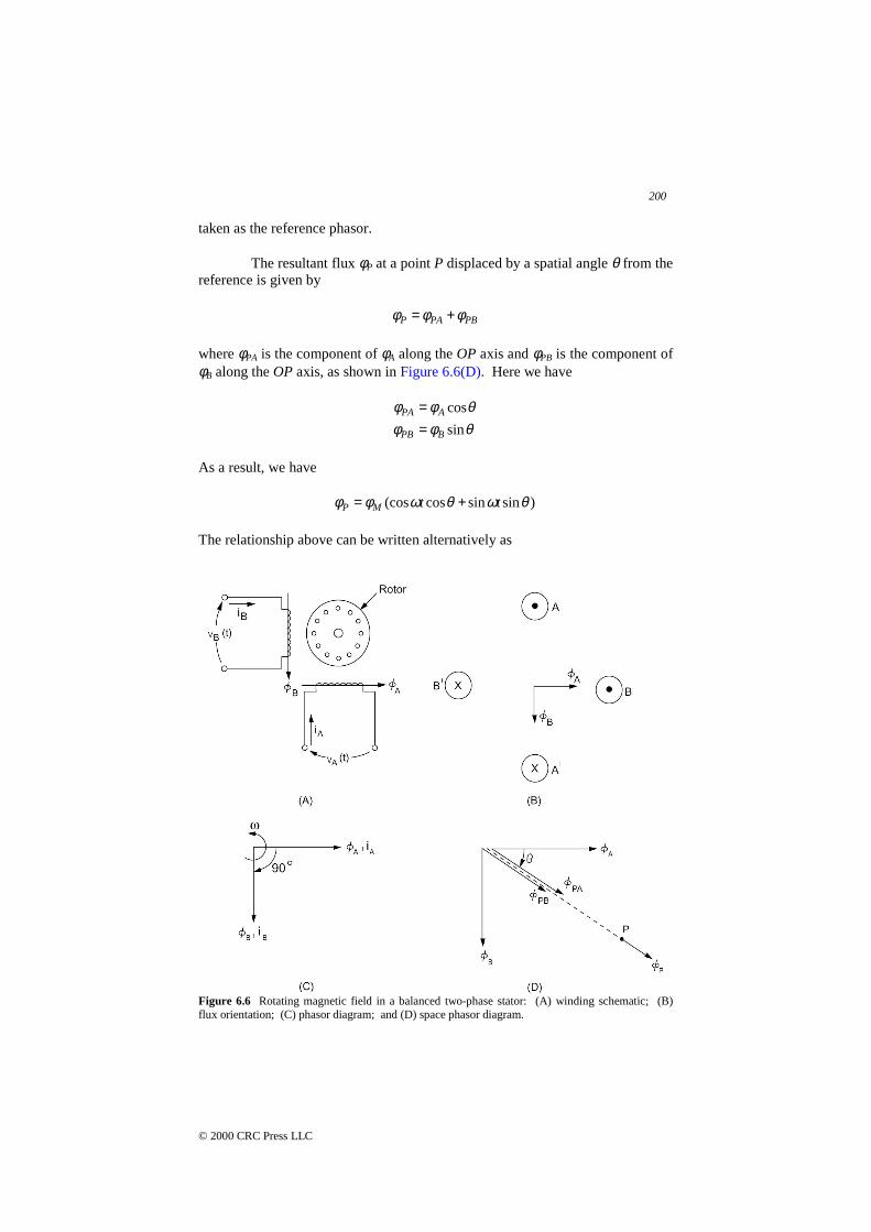
To understand the operation of common single-phase induction motors,it is necessary to start by discussing two-phase induction machines. In a truetwo-phase machine two stator windings, labeled AA′ and BB′, are placed at 90°spatial displacement as shown in Figure 6.6. The voltages υA and υB form a setof balanced two-phase voltages with a 90° time (or phase) displacement.Assuming that the two windings are identical, then the resulting flux φA and φB
are given by
tMA ωφφ cos= (6.17)
tt MMB ωφωφφ sin)90cos( =−= ! (6.18)
where φM is the peak value of the flux. In Figure 6.6(B), the flux φA is shown tobe at right angles to φB in space. It is clear that because of Eqs. (6.17) and(6.18), the phasor relation between φA and φB is shown in Figure 6.6(C) with φA
200
© 2000 CRC Press LLC
taken as the reference phasor.
The resultant flux φP at a point P displaced by a spatial angle θ from thereference is given by
PBPAP φφφ +=
where φPA is the component of φA along the OP axis and φPB is the component ofφB along the OP axis, as shown in Figure 6.6(D). Here we have
θφφθφφ
sin
cos
BPB
APA
==
As a result, we have
)sinsincos(cos θωθωφφ ttMP +=
The relationship above can be written alternatively as
Figure 6.6 Rotating magnetic field in a balanced two-phase stator: (A) winding schematic; (B)flux orientation; (C) phasor diagram; and (D) space phasor diagram.

201
© 2000 CRC Press LLC
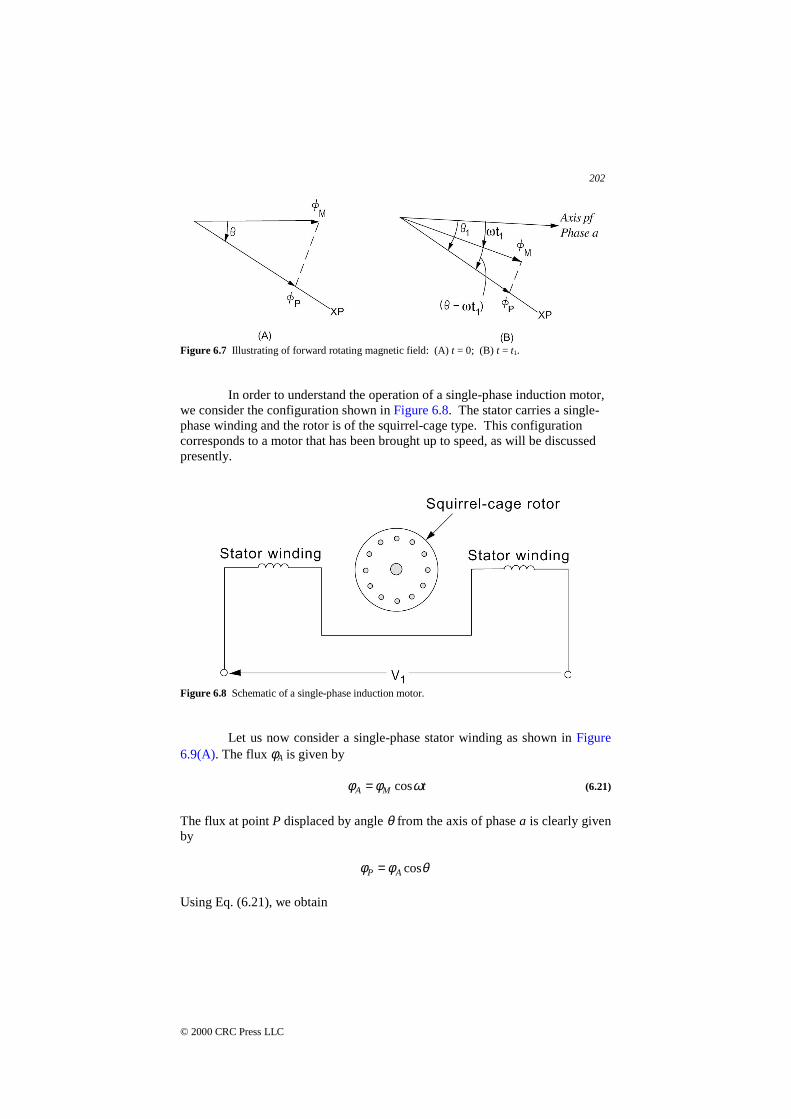
)cos( tMP ωθφφ −= (6.19)
The flux at point P is a function of time and the spatial angle θ, and has aconstant amplitude φM. this result is similar to that obtained earlier for thebalanced three-phase induction motor.
The flux φP can be represented by a phasor φM that is coincident withthe axis of phase a at t = 0. The value of φP is φM cos θ at that instant as shownin Figure 6.7(A). At the instant t = t1, the phasor φM has rotated an angle of ωt1
in the positive direction of θ, as shown in Figure 6.7(B). The value of φP is seento be φM cos (θ - ωt1) at that instant. It is thus clear that the flux waveform is arotating field that travels at an angular velocity ω in the forward direction ofincrease in θ.
The result obtained here for a two-phase stator winding set and for athree-phase stator winding set can be extended to an N-phase system. In thiscase the N windings are placed at spatial angles of 2π/N and excited bysinusoidal voltages of time displacement 2π/N. Our analysis proceeds asfollows. The flux waveforms are given by
−−=
⋅⋅⋅
−=
=
Nit
Nt
t
Mi
M
M
πωφφ
πωφφ
ωφφ
2)1(cos
2cos
cos
2
1
The resultant flux at a point P can be shown to be given by:
∑=
=N
iPiP
1
φφ
)cos(2
tN M
P ωθφφ −= (6.20)
A rotating magnetic field of constant magnitude will be produced by anN-phase winding excited by balanced N-phase currents when each phase isdisplaced 2π/N electrical degrees from the next phase in space.
202
© 2000 CRC Press LLC
Figure 6.7 Illustrating of forward rotating magnetic field: (A) t = 0; (B) t = t1.
In order to understand the operation of a single-phase induction motor,we consider the configuration shown in Figure 6.8. The stator carries a single-phase winding and the rotor is of the squirrel-cage type. This configurationcorresponds to a motor that has been brought up to speed, as will be discussedpresently.
Figure 6.8 Schematic of a single-phase induction motor.
Let us now consider a single-phase stator winding as shown in Figure6.9(A). The flux φA is given by
tMA ωφφ cos= (6.21)
The flux at point P displaced by angle θ from the axis of phase a is clearly givenby
θφφ cosAP =
Using Eq. (6.21), we obtain
203
© 2000 CRC Press LLC
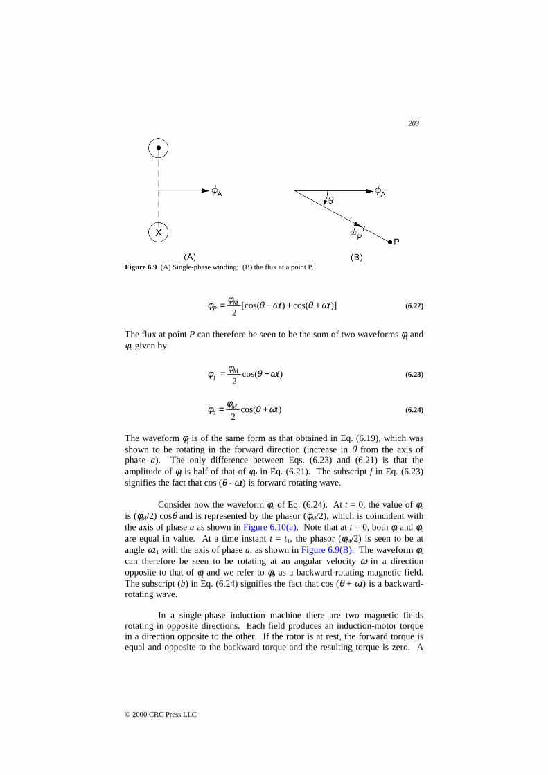
Figure 6.9 (A) Single-phase winding; (B) the flux at a point P.
)]cos()[cos(2
ttMP ωθωθφφ ++−= (6.22)
The flux at point P can therefore be seen to be the sum of two waveforms φf andφb given by
)cos(2
tMf ωθφφ −= (6.23)
)cos(2
tMb ωθφφ += (6.24)
The waveform φf is of the same form as that obtained in Eq. (6.19), which wasshown to be rotating in the forward direction (increase in θ from the axis ofphase a). The only difference between Eqs. (6.23) and (6.21) is that theamplitude of φf is half of that of φP in Eq. (6.21). The subscript f in Eq. (6.23)signifies the fact that cos (θ - ωt) is forward rotating wave.
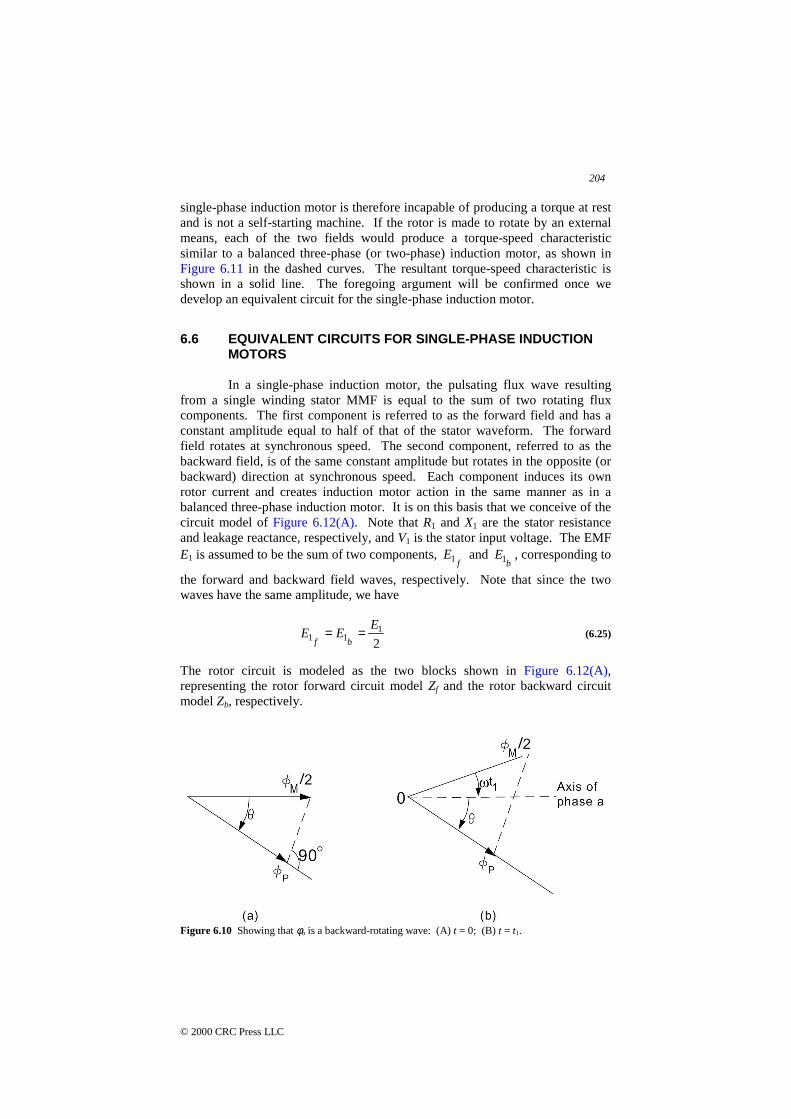
Consider now the waveform φb of Eq. (6.24). At t = 0, the value of φb
is (φM/2) cosθ and is represented by the phasor (φM/2), which is coincident withthe axis of phase a as shown in Figure 6.10(a). Note that at t = 0, both φf and φb
are equal in value. At a time instant t = t1, the phasor (φM/2) is seen to be atangle ωt1 with the axis of phase a, as shown in Figure 6.9(B). The waveform φb
can therefore be seen to be rotating at an angular velocity ω in a directionopposite to that of φf and we refer to φb as a backward-rotating magnetic field.The subscript (b) in Eq. (6.24) signifies the fact that cos (θ + ωt) is a backward-rotating wave.
In a single-phase induction machine there are two magnetic fieldsrotating in opposite directions. Each field produces an induction-motor torquein a direction opposite to the other. If the rotor is at rest, the forward torque isequal and opposite to the backward torque and the resulting torque is zero. A
204
© 2000 CRC Press LLC
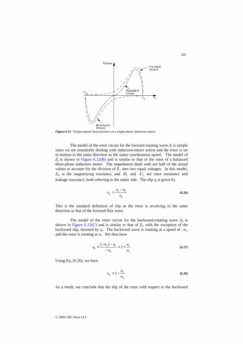
single-phase induction motor is therefore incapable of producing a torque at restand is not a self-starting machine. If the rotor is made to rotate by an externalmeans, each of the two fields would produce a torque-speed characteristicsimilar to a balanced three-phase (or two-phase) induction motor, as shown inFigure 6.11 in the dashed curves. The resultant torque-speed characteristic isshown in a solid line. The foregoing argument will be confirmed once wedevelop an equivalent circuit for the single-phase induction motor.
6.6 EQUIVALENT CIRCUITS FOR SINGLE-PHASE INDUCTIONMOTORS
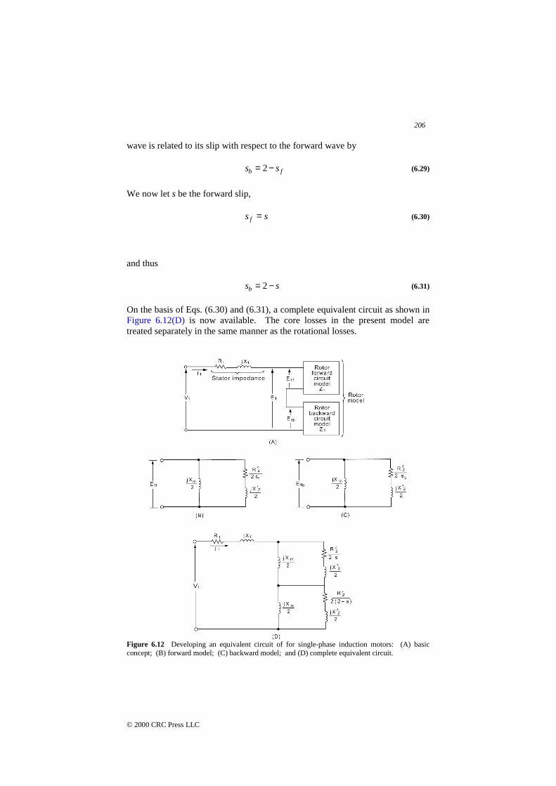
In a single-phase induction motor, the pulsating flux wave resultingfrom a single winding stator MMF is equal to the sum of two rotating fluxcomponents. The first component is referred to as the forward field and has aconstant amplitude equal to half of that of the stator waveform. The forwardfield rotates at synchronous speed. The second component, referred to as thebackward field, is of the same constant amplitude but rotates in the opposite (orbackward) direction at synchronous speed. Each component induces its ownrotor current and creates induction motor action in the same manner as in abalanced three-phase induction motor. It is on this basis that we conceive of thecircuit model of Figure 6.12(A). Note that R1 and X1 are the stator resistanceand leakage reactance, respectively, and V1 is the stator input voltage. The EMFE1 is assumed to be the sum of two components,
fE1 and
bE1 , corresponding to
the forward and backward field waves, respectively. Note that since the twowaves have the same amplitude, we have
21
11E
EEbf== (6.25)
The rotor circuit is modeled as the two blocks shown in Figure 6.12(A),representing the rotor forward circuit model Zf and the rotor backward circuitmodel Zb, respectively.
Figure 6.10 Showing that φb is a backward-rotating wave: (A) t = 0; (B) t = t1.
205
© 2000 CRC Press LLC
Figure 6.11 Torque-speed characteristics of a single-phase induction motor.
The model of the rotor circuit for the forward rotating wave Zf is simplesince we are essentially dealing with induction-motor action and the rotor is setin motion in the same direction as the stator synchronous speed. The model ofZf is shown in Figure 6.12(B) and is similar to that of the rotor of a balancedthree-phase induction motor. The impedances dealt with are half of the actualvalues to account for the division of E1 into two equal voltages. In this model,Xm is the magnetizing reactance, and 2R′ and 2X ′ are rotor resistance and
leakage reactance, both referring to the stator side. The slip sf is given by
s
rsf n
nns
−= (6.26)
This is the standard definition of slip as the rotor is revolving in the samedirection as that of the forward flux wave.
The model of the rotor circuit for the backward-rotating wave Zb isshown in Figure 6.12(C) and is similar to that of Zf, with the exception of thebackward slip, denoted by sb. The backward wave is rotating at a speed of –ns,and the rotor is rotating at nr. We thus have
s
r
s
rsb n
n
n
nns +=
−−−= 1
)((6.27)
Using Eq. (6.26), we have
s
rfs
n
n1−= (6.28)
As a result, we conclude that the slip of the rotor with respect to the backward
206
© 2000 CRC Press LLC
wave is related to its slip with respect to the forward wave by
fb ss −= 2 (6.29)
We now let s be the forward slip,
ss f = (6.30)
and thus
ssb −= 2 (6.31)
On the basis of Eqs. (6.30) and (6.31), a complete equivalent circuit as shown inFigure 6.12(D) is now available. The core losses in the present model aretreated separately in the same manner as the rotational losses.
Figure 6.12 Developing an equivalent circuit of for single-phase induction motors: (A) basicconcept; (B) forward model; (C) backward model; and (D) complete equivalent circuit.

207
© 2000 CRC Press LLC
The forward impedance Zf is obtained as the parallel combination of(jXm/2) and )]2()2[( 22 sXjsR ′+′ , given by
]2)[()2(
)]2()2)[(2(
22
22
XXjsR
XjsRXjZ
m
mf ′++′
′+′= (6.32)
Similarly, for the backward impedance, we get
]2)[()2(2[
)]2()]2(2)[2(
22
22
XXjsR
XjsRXjZ
m
mb ′++−′
′+−′= (6.33)
Note that with the rotor at rest, nr = 0, and thus with s = 1, we get Zf = Zb.
Example 6.5The following parameters are available for a 60-Hz four-pole single-phase 110-V ½-hp induction motor:
R1 = 1.5 Ω 2R′ = 3 ΩX1 = 2.4 Ω 2X ′ = 2.4 ΩXm = 73.4 Ω
Calculate Zf, Zb, and the input impedance of the motor at a slip of 0.05.
Solution
Ω+=
∠=+
+=
851.14294.17
654.40796.229.3730
)2.130(7.36
j
j
jjZ f
!
The result above is a direct application of Eq. (6.32). Similarly, using Eq.(6.33), we get
Ω+=
Ω∠=+
+=
766.1721.0
502.5838.19.37)95.15.1(
]2.1)95.15.1[(7.36
j
j
jjZb
!
We observe here that fZ is much larger than bZ at this slip, in contrast to the
situation at starting (s = 1), for which Zf = Zb.
The input impedance Zi is obtained as
Ω∠=
+=++=
36.43841.26
428.18515.191
!
jZZZZ bfi
Equations (6.32) and (6.33) yield the forward and backward

208
© 2000 CRC Press LLC
impedances on the basis of complex number arithmetic. The results can bewritten in the rectangular forms
fff jXRZ += (6.34)
and
bbb jXRZ += (6.35)
Using Eq. (6.32), we can write
22
2
2tf
mff
Xa
XaR
+= (6.36)
and
)( 22 XXa
Xa
RX tf
mf
ff ′+= (6.37)
where
s
Ra f
2′= (6.38)
mt XXX +′= 2 (6.39)
In a similar manner we have, using Eq. (6.33),
22
2
2tb
mbb
Xa
XaR
+= (6.40)
)( 22 XXa
Xa
RX tb
mb
bb ′+= (6.41)
where
s
Rab −
′=
22 (6.42)
It is often desirable to introduce some approximations in the formulasjust derived. As is the usual case, for Xt > 10 ab, we can write an approximationto Eq. (6.40) as
209
© 2000 CRC Press LLC
2
2
≅
t
mbb
X
XaR (6.43)
As a result, by substitution in Eq. (6.41), we get
m
bb
t
mb X
Ra
X
XXX +
′≅
22 (6.44)
We can introduce further simplifications by assuming that Xm/Xt ≅ 1, toobtain from Eq. (6.43)
s
RaR bb −
′=≅
22 2 (6.45)
Equation (6.44) reduces to the approximate form
m
bb X
XX
2
a
2
22 +′
≅ (6.46)
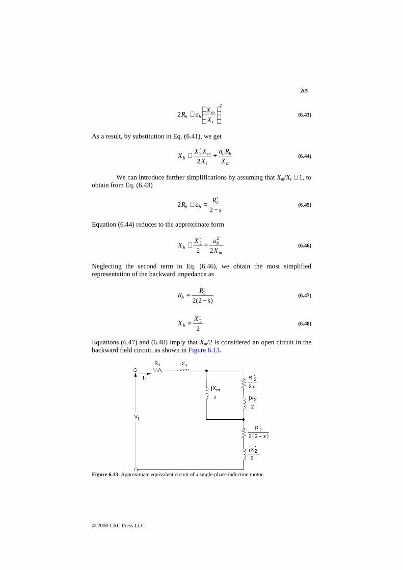
Neglecting the second term in Eq. (6.46), we obtain the most simplifiedrepresentation of the backward impedance as
)2(22
s
RRb −
′= (6.47)
22X
Xb′
= (6.48)
Equations (6.47) and (6.48) imply that Xm/2 is considered an open circuit in thebackward field circuit, as shown in Figure 6.13.
Figure 6.13 Approximate equivalent circuit of a single-phase induction motor.
210
© 2000 CRC Press LLC
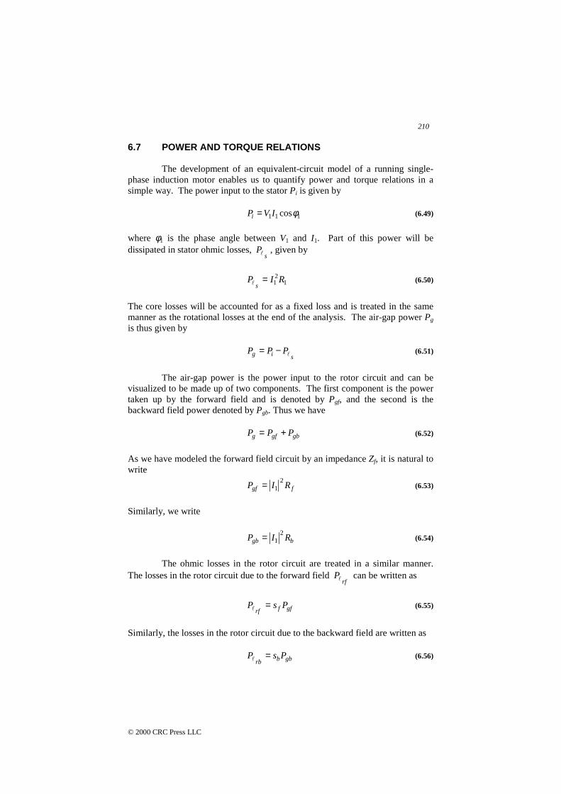
6.7 POWER AND TORQUE RELATIONS
The development of an equivalent-circuit model of a running single-phase induction motor enables us to quantify power and torque relations in asimple way. The power input to the stator Pi is given by
111 cosφIVPi = (6.49)
where φ1 is the phase angle between V1 and I1. Part of this power will bedissipated in stator ohmic losses,
sP" , given by
121 RIP
s=" (6.50)
The core losses will be accounted for as a fixed loss and is treated in the samemanner as the rotational losses at the end of the analysis. The air-gap power Pg
is thus given by
sig PPP "−= (6.51)
The air-gap power is the power input to the rotor circuit and can bevisualized to be made up of two components. The first component is the powertaken up by the forward field and is denoted by Pgf, and the second is thebackward field power denoted by Pgb. Thus we have
gbgfg PPP += (6.52)
As we have modeled the forward field circuit by an impedance Zf, it is natural towrite
fgf RIP2
1= (6.53)
Similarly, we write
bgb RIP2
1= (6.54)
The ohmic losses in the rotor circuit are treated in a similar manner.The losses in the rotor circuit due to the forward field
rfP" can be written as
gffrfPsP =" (6.55)
Similarly, the losses in the rotor circuit due to the backward field are written as
gbbrbPsP =" (6.56)
211
© 2000 CRC Press LLC
Equations (6.55) and (6.56) are based on arguments similar to those used withthe balanced three-phase induction motor. Specifically, the total rotor equivalentresistance in the forward circuit is given by
frf s
RR
22′= (6.57)
This is written as
f
frf
s
sRRR
2
)1(
222 −′
+′
= (6.58)
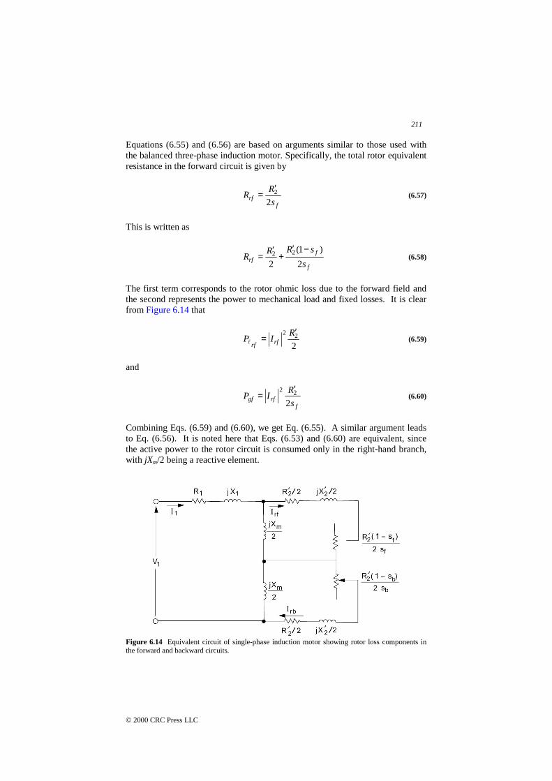
The first term corresponds to the rotor ohmic loss due to the forward field andthe second represents the power to mechanical load and fixed losses. It is clearfrom Figure 6.14 that
222 R
IP rfrf
′=" (6.59)
and
frfgf
s
RIP
222 ′
= (6.60)
Combining Eqs. (6.59) and (6.60), we get Eq. (6.55). A similar argument leadsto Eq. (6.56). It is noted here that Eqs. (6.53) and (6.60) are equivalent, sincethe active power to the rotor circuit is consumed only in the right-hand branch,with jXm/2 being a reactive element.
Figure 6.14 Equivalent circuit of single-phase induction motor showing rotor loss components inthe forward and backward circuits.
212
© 2000 CRC Press LLC
The net power form the rotor circuit is denoted by Pm and is given by
mbmfm PPP += (6.61)
The component Pmf is due to the forward circuit and is given by
rfgfmf PPP "−= (6.62)
Using Eq. (6.55), we get
gffmf PsP )1( −= (6.63)
Similarly, Pmb is due to the backward circuit and is given by
rbgbmb PPP "−= (6.64)
Using Eq. (6.56), we get
gbbmb PsP )1( −= (6.65)
Recall that
ss
ss
b
f
−=
=
2
As a result,
gfmf PsP )1( −= (6.66)
gbmb PsP )1( −= (6.67)
We now substitute Eqs. (6.66) and (6.67) into Eq. (6.61), to obtain
))(1( gbgfm PPsP −−= (6.68)
The shaft power output Po can now be written as
corerot PPPP mo −−= (6.69)
The rotational losses are denoted by Prot and the core losses are denoted by Pcore.
The output torque To is obtained as

213
© 2000 CRC Press LLC
r
oo
PT
ω= (6.70)
If fixed losses are neglected, then
)1( s
PT
s
mm −=ω
(6.71)
As a result, using Eq. (6.68), we get
)(1
gbgfs
m PPT −=ω
(6.72)
The torque due to the forward field is
s
gf
r
mfmf
PPT
ωω== (6.73)
The torque due to the backward field is
s
gb
r
mbmb
PPT
ωω−== (6.74)
It is thus clear that the net mechanical torque is the algebraic sum of a forwardtorque Tmf (positive) and a backward torque Tmb (negative). Note that at starting,s = 1 and Rf = Rb, and as a result Pgf = Pgb, giving zero output torque. Thisconfirms our earlier statements about the need for starting mechanisms for asingle-phase induction motor. This is discussed in the next section.
Example 6.6For the single-phase induction motor of Example 6.5, it is necessary to find thepower and torque output and the efficiency when running at a slip of 5 percent.Neglect core and rotational losses.
SolutionIn Example 6.5 we obtained
!36.43841.26 ∠=iZ
As a result, with V1 = 0110∠ , we obtain
A 36.43098.436.43841.26
01101
!!
−∠=∠∠=I
214
© 2000 CRC Press LLC
The power factor is thus
727.036.43coscos 1 == !φ
The power input is
W76.327cos 1111 == φIVP
We have from Example 6.5 for s = 0.05,
Rf = 17.294 Ω Rb = 0.721 Ω
Thus we have
W109.12)721.0()098.4(
W46.290)294.17()098.4(
221
221
===
===
bgb
fgf
RIP
RIP
The output power is thus obtained as
W43.264)109.1246.290(95.0
))(1(
=−=
−−= gbgfm PPsP
As we have a four-pole machine, we get
rad/s 5.18860
2
r/min 18004
)60(120
==
==
ss
s
n
n
πω
The output torque is therefore obtained as
mN 4767.15.188
109.1246.290
)(1
⋅=−=
−= gbgfs
m PPTω
The efficiency is now calculated as
8068.076.327
43.264
1
===P
Pmη
It is instructive to account for the losses in the motor. Here we have thestatic ohmic losses obtained as
215
© 2000 CRC Press LLC
W193.25)5.1()098.4( 21
21 === RIP
s"
The forward rotor losses are
W523.14)46.290(05.0 === gfrfsPP"
The backward rotor losses are
W613.23)109.12(95.1)2( ==−= gbrbPsP"
The sum of the losses is
W329.63613.23523.14193.25 =++="P
The power output and losses should match the power input
W76.32733.6343.264 =+=+ "PPm
which is indeed the case.
Example 6.7A single-phase induction motor takes an input power of 490 W at a power factorof 0.57 lagging from a 110-V supply when running at a slip of 5 percent.Assume that the rotor resistance and reactance are 1.78 Ω and 1.28 Ω,respectively, and that the magnetizing reactance is 25 Ω. Find the resistance andreactance of the stator.
SolutionThe equivalent circuit of the motor yields
6232.04125.0
)5.1264.0()]95.1(278.1[
)5.12(64.0)]95.1(278.1[
3057.86818.5)5.1264.0()]05.0(278.1[
)5.12(64.0)]5.0(278.1[
jj
jjZ
jj
jjZ
b
f
+=++
+=
+=++
+=
As a result of the problem specifications
Pi = 490 W cos φ = 0.57 V = 110
!2488.55815.7)57.0(110
590
cos−∠===
φV
PI i
i
Thus the input impedance is
216
© 2000 CRC Press LLC
5651.11023.82498.55815.7
110j
I
VZ
ii +=∠== !
The stator impedance is obtained as
Ω+=+−= 636.29287.1)(1 jZZZZ bfi
6.8 STARTING SINGLE-PHASE INDUCTION MOTORS
We have shown earlier that a single-phase induction motor with onestator winding is not capable of producing a torque at starting [see, for example,Eq. (6.68) with s = 1]. Once the motor is running, it will continue to do so, sincethe forward field torque dominates that of the backward field component. Wehave also seen that with two stator windings that are displaced by 90° in spaceand with two-phase excitation a purely forward rotating field is produced, andthis form of a motor (like the balanced three-phase motor) is self-starting.
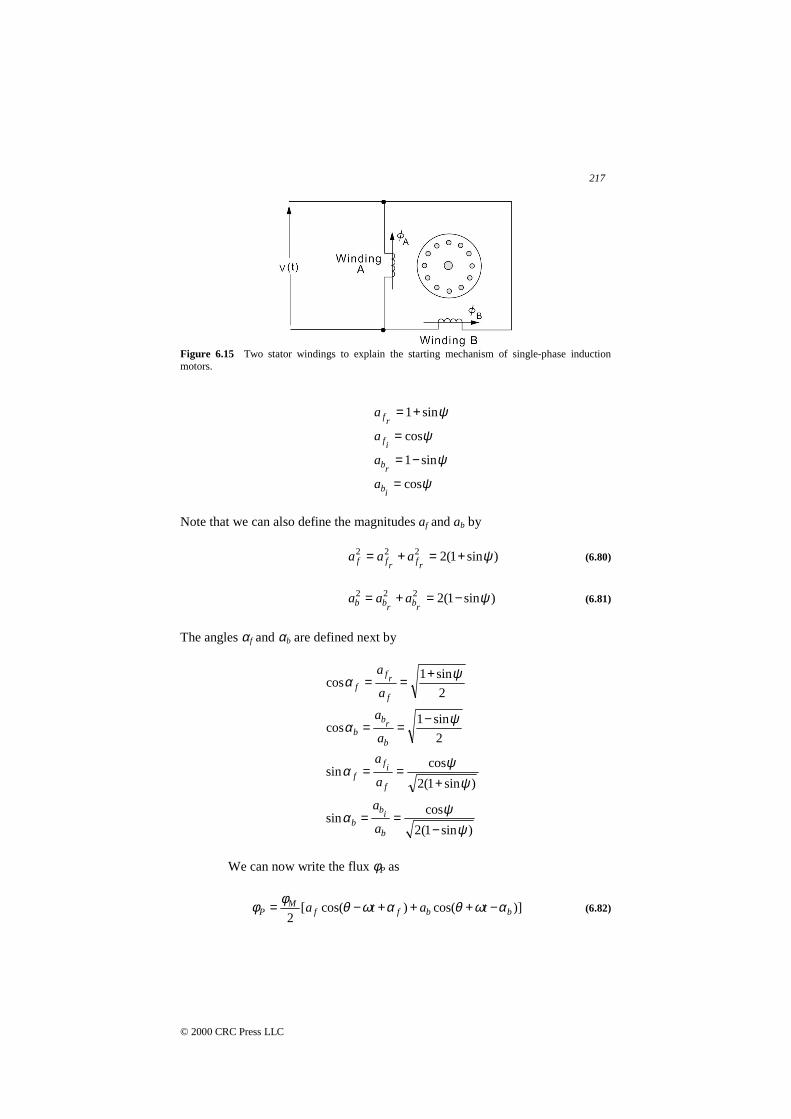
Methods of starting a single-phase induction motor rely on the fact thatgiven two stator windings displaced by 90° in space, a starting torque will resultif the flux in one of the windings lags that of the other by a certain phase angleψ. To verify this, we consider the situation shown in Figure 6.15. Assume that
tMA ωφφ cos= (6.75)
)cos( ψωφφ −= tMB (6.76)
Clearly, the flux at P is given by the sum of φPA and φPB
)]cos()[cos(2
ttM
AP ωθωθφφ ++−= (6.77)
)]cos()[cos(sin
)]sin()[sin(cos2
tt
ttM
BP
ωθωθψ
ωθωθψφφ
+−−+
−++=(6.78)
The flux at P is therefore obtained as
)]sin()cos(
)sin()cos([2
tata
tata
rbrb
ifrfM
P
ωθωθ
ωθωθφφ
++++
−+−=(6.79)
where we have
217
© 2000 CRC Press LLC
Figure 6.15 Two stator windings to explain the starting mechanism of single-phase inductionmotors.
ψsin1+=rfa
ψcos=if
a
ψsin1−=rba
ψcos=iba
Note that we can also define the magnitudes af and ab by
)sin1(2222 ψ+=+=rfrff aaa (6.80)
)sin1(2222 ψ−=+=rbrbb aaa (6.81)
The angles αf and αb are defined next by
2
sin1cos
ψα +==f
rf
fa
a
2
sin1cos
ψα −==b
rb
b a
a
)sin1(2
cossin
ψψα
+==
f
if
f a
a
)sin1(2
cossin
ψψα
−==
b
ib
b a
a
We can now write the flux φP as
)]cos()cos([2
bbffM
P tata αωθαωθφφ −+++−= (6.82)
218
© 2000 CRC Press LLC
It is clear that φP is the sum of a forward rotating component φf and a backwardrotating component φb given by
)()( tt bfP φφφ += (6.83)
where
)cos(2
)( fMf
f ta
t αωθφ
φ +−= (6.84)
)cos(2
)( bMb
b ta
t αωθφφ −+= (6.85)
Let us note here that from Eqs. (6.80) and (6.81), we can see that
bf aa > (6.86)
As a result, the magnitude of the forward rotating wave is larger than that of thebackward rotating wave. It is clear that for the arrangement of Figure 6.15, astarting torque should result. This is the basis of the starting mechanisms forsingle-phase induction motors.
6.9 SINGLE-PHASE INDUCTION MOTOR TYPES
Single-phase induction motors are referred to by names that describethe method of starting. A number of types of single-phase induction motors arenow discussed.
Split-Phase Motors
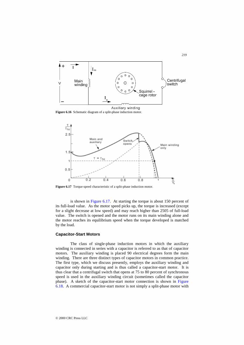
A single-phase induction motor with two distinct windings on the statorthat are displaced in space by 90 electrical degrees is called a split-phase motor.The main (or running) winding has a lower R/X ratio than the auxiliary (orstarting) winding. A starting switch disconnects the auxiliary windings whenthe motor is running at approximately 75 to 80 percent of synchronous speed.The switch is centrifugally operated. The rotor of a split-phase motor is of thesquirrel-cage type. At starting, the two windings are connected in parallel acrossthe line as shown in Figure 6.16.
The split-phase design is one of the oldest single-phase motors and ismost widely used in the ratings of 0.05 to 0.33 hp. A split-phase motor is usedin machine tools, washing machines, oil burners, and blowers, to name just afew of its applications.
The torque-speed characteristic of a typical split-phase induction motor
219
© 2000 CRC Press LLC
Figure 6.16 Schematic diagram of a split-phase induction motor.
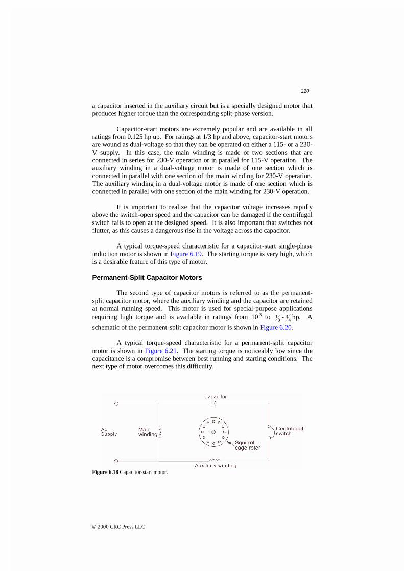
Figure 6.17 Torque-speed characteristic of a split-phase induction motor.
is shown in Figure 6.17. At starting the torque is about 150 percent ofits full-load value. As the motor speed picks up, the torque is increased (exceptfor a slight decrease at low speed) and may reach higher than 2505 of full-loadvalue. The switch is opened and the motor runs on its main winding alone andthe motor reaches its equilibrium speed when the torque developed is matchedby the load.
Capacitor-Start Motors
The class of single-phase induction motors in which the auxiliarywinding is connected in series with a capacitor is referred to as that of capacitormotors. The auxiliary winding is placed 90 electrical degrees form the mainwinding. There are three distinct types of capacitor motors in common practice.The first type, which we discuss presently, employs the auxiliary winding andcapacitor only during starting and is thus called a capacitor-start motor. It isthus clear that a centrifugal switch that opens at 75 to 80 percent of synchronousspeed is used in the auxiliary winding circuit (sometimes called the capacitorphase). A sketch of the capacitor-start motor connection is shown in Figure6.18. A commercial capacitor-start motor is not simply a split-phase motor with
220
© 2000 CRC Press LLC
a capacitor inserted in the auxiliary circuit but is a specially designed motor thatproduces higher torque than the corresponding split-phase version.
Capacitor-start motors are extremely popular and are available in allratings from 0.125 hp up. For ratings at 1/3 hp and above, capacitor-start motorsare wound as dual-voltage so that they can be operated on either a 115- or a 230-V supply. In this case, the main winding is made of two sections that areconnected in series for 230-V operation or in parallel for 115-V operation. Theauxiliary winding in a dual-voltage motor is made of one section which isconnected in parallel with one section of the main winding for 230-V operation.The auxiliary winding in a dual-voltage motor is made of one section which isconnected in parallel with one section of the main winding for 230-V operation.
It is important to realize that the capacitor voltage increases rapidlyabove the switch-open speed and the capacitor can be damaged if the centrifugalswitch fails to open at the designed speed. It is also important that switches notflutter, as this causes a dangerous rise in the voltage across the capacitor.
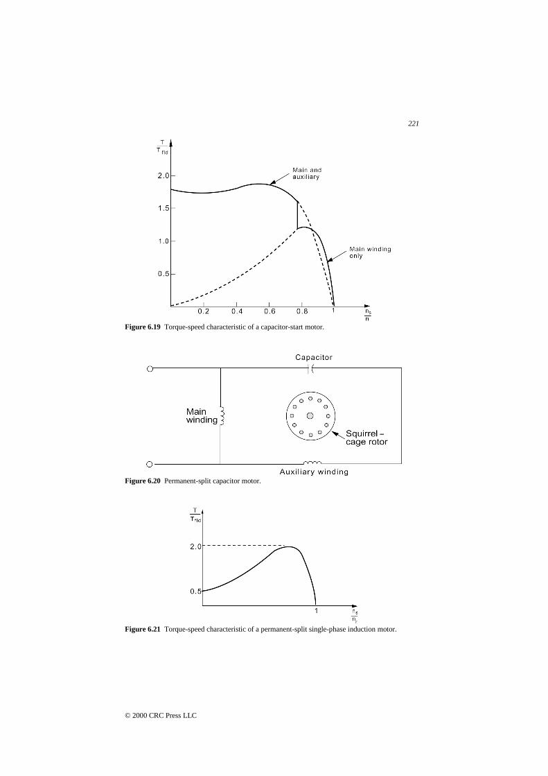
A typical torque-speed characteristic for a capacitor-start single-phaseinduction motor is shown in Figure 6.19. The starting torque is very high, whichis a desirable feature of this type of motor.
Permanent-Split Capacitor Motors
The second type of capacitor motors is referred to as the permanent-split capacitor motor, where the auxiliary winding and the capacitor are retainedat normal running speed. This motor is used for special-purpose applicationsrequiring high torque and is available in ratings from 10-3 to 3
1 - 43 hp. A
schematic of the permanent-split capacitor motor is shown in Figure 6.20.
A typical torque-speed characteristic for a permanent-split capacitormotor is shown in Figure 6.21. The starting torque is noticeably low since thecapacitance is a compromise between best running and starting conditions. Thenext type of motor overcomes this difficulty.
Figure 6.18 Capacitor-start motor.
221
© 2000 CRC Press LLC
Figure 6.19 Torque-speed characteristic of a capacitor-start motor.
Figure 6.20 Permanent-split capacitor motor.
Figure 6.21 Torque-speed characteristic of a permanent-split single-phase induction motor.

222
© 2000 CRC Press LLC
Two-Value Capacitor Motors
A two-value capacitor motor starts with one value of capacitors inseries with the auxiliary winding and runs with a different capacitance value.This change can be done either using two separate capacitors or through the useof an autotransformer. This motor has been replaced by the capacitor-startmotor for applications such as refrigerators and compressors.
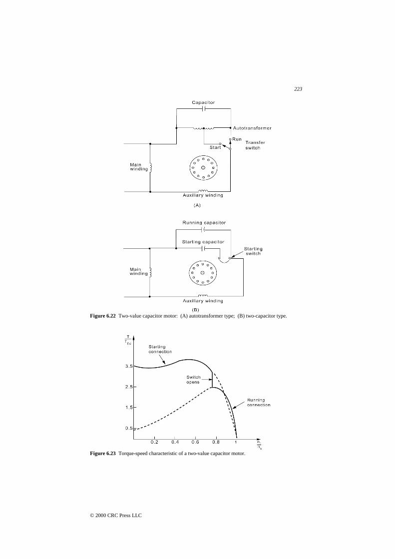
For the motor using an autotransformer, a transfer switch is used tochange the tap on the autotransformer, as shown in Figure 6.22(A). Thisarrangement appears to be obsolete now and the two-capacitor mechanismillustrated in Figure 6.22(B) is used.
A typical torque-speed characteristic for a two-value capacitor motor isshown in Figure 6.23. Note that optimum starting and running conditions can beaccomplished in this type of motor.
Repulsion-Type Motors
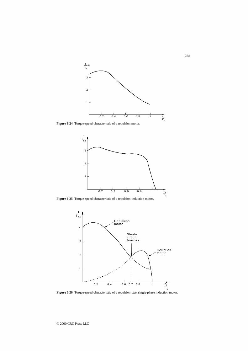
A repulsion motor is a single-phase motor with power connected to thestator winding and a rotor whose winding is connected to a commutator. Thebrushes on the commutator are short-circuited and are positioned such that thereis an angle of 20 to 30° between the magnetic axis of the stator winding and themagnetic axis of the rotor winding. A representative torque-speed characteristicfor a repulsion motor is shown in Figure 6.24. A repulsion motor is a variable-speed motor.
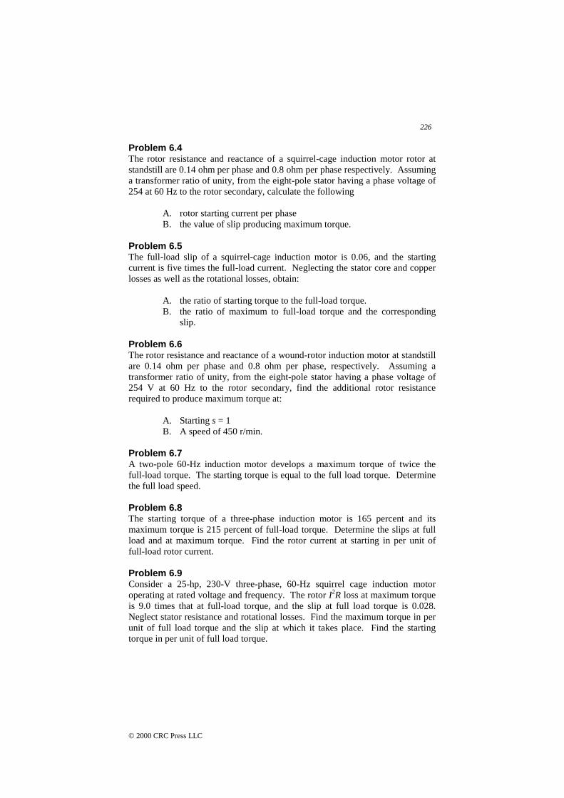
If in addition to the repulsion winding, a squirrel-cage type of windingis embedded in the rotor, we have a repulsion-induction motor. The torque-speed characteristic for a repulsion-induction motor is shown in Figure 6.25 andcan be though of as a combination of the characteristics of a single-phaseinduction motor and that of a straight repulsion motor.
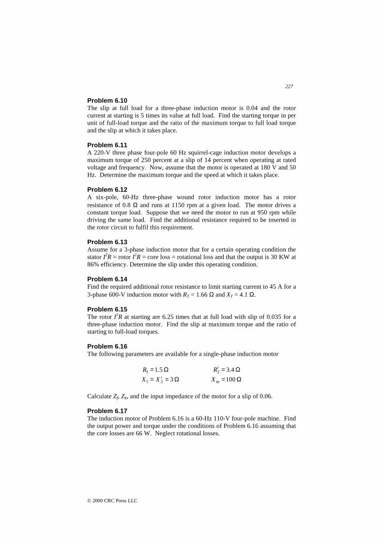
A repulsion-start induction motor is a single-phase motor with the samewindings as a repulsion motor, but at a certain speed the rotor winding is shortcircuited to give the equivalent of a squirrel-cage winding. The repulsion-startmotor is the first type of single-phase motors that gained wide acceptance. Inrecent years, however, it has been replaced by capacitor-type motors. A typicaltorque-speed characteristic of a repulsion-start induction motor is shown inFigure 6.26.
Shaded-Pole Induction Motors
For applications requiring low power of ¼ hp or less, a shaded-poleinduction motor is the standard general-purpose device for constant-speedapplications. The torque characteristics of a shaded-pole motor are similar tothose of a permanent-split capacitor motor as shown in Figure 6.27.
223
© 2000 CRC Press LLC
Figure 6.22 Two-value capacitor motor: (A) autotransformer type; (B) two-capacitor type.
Figure 6.23 Torque-speed characteristic of a two-value capacitor motor.
224
© 2000 CRC Press LLC
Figure 6.24 Torque-speed characteristic of a repulsion motor.
Figure 6.25 Torque-speed characteristic of a repulsion-induction motor.
Figure 6.26 Torque-speed characteristic of a repulsion-start single-phase induction motor.

225
© 2000 CRC Press LLC
Figure 6.27 Torque-speed characteristic of a shaded-pole induction motor.
PROBLEMS
Problem 6.1Determine the number of poles, the slip, and the frequency of the rotor currentsat rated load for three-phase, induction motors rated at:
A. 220 V, 50 Hz, 1440 r/min.B. 120 V, 400 Hz, 3800 r/min.
Problem 6.2A 50-HP, 440-V, three-phase, 60-Hz, six-pole, Y-connected induction motor hasthe following parameters per phase:
R2 = 0.15 ohmR1 = 0.12 ohmGc = 6 × 10⁻³ siemensXT =0.75 ohmBm = 0.07 siemens
The rotational losses are equal to the stator hysteresis and eddy-current losses.For a slip of 4 percent, find the following
A. the line current and power factor.B. the horsepower output.C. the starting torque.
Problem 6.3Use MATLAB to verify the results of Problem 6.2.
226
© 2000 CRC Press LLC
Problem 6.4The rotor resistance and reactance of a squirrel-cage induction motor rotor atstandstill are 0.14 ohm per phase and 0.8 ohm per phase respectively. Assuminga transformer ratio of unity, from the eight-pole stator having a phase voltage of254 at 60 Hz to the rotor secondary, calculate the following
A. rotor starting current per phaseB. the value of slip producing maximum torque.
Problem 6.5The full-load slip of a squirrel-cage induction motor is 0.06, and the startingcurrent is five times the full-load current. Neglecting the stator core and copperlosses as well as the rotational losses, obtain:
A. the ratio of starting torque to the full-load torque.B. the ratio of maximum to full-load torque and the corresponding
slip.
Problem 6.6The rotor resistance and reactance of a wound-rotor induction motor at standstillare 0.14 ohm per phase and 0.8 ohm per phase, respectively. Assuming atransformer ratio of unity, from the eight-pole stator having a phase voltage of254 V at 60 Hz to the rotor secondary, find the additional rotor resistancerequired to produce maximum torque at:
A. Starting s = 1B. A speed of 450 r/min.
Problem 6.7A two-pole 60-Hz induction motor develops a maximum torque of twice thefull-load torque. The starting torque is equal to the full load torque. Determinethe full load speed.
Problem 6.8The starting torque of a three-phase induction motor is 165 percent and itsmaximum torque is 215 percent of full-load torque. Determine the slips at fullload and at maximum torque. Find the rotor current at starting in per unit offull-load rotor current.
Problem 6.9Consider a 25-hp, 230-V three-phase, 60-Hz squirrel cage induction motoroperating at rated voltage and frequency. The rotor I2R loss at maximum torqueis 9.0 times that at full-load torque, and the slip at full load torque is 0.028.Neglect stator resistance and rotational losses. Find the maximum torque in perunit of full load torque and the slip at which it takes place. Find the startingtorque in per unit of full load torque.
227
© 2000 CRC Press LLC
Problem 6.10The slip at full load for a three-phase induction motor is 0.04 and the rotorcurrent at starting is 5 times its value at full load. Find the starting torque in perunit of full-load torque and the ratio of the maximum torque to full load torqueand the slip at which it takes place.
Problem 6.11A 220-V three phase four-pole 60 Hz squirrel-cage induction motor develops amaximum torque of 250 percent at a slip of 14 percent when operating at ratedvoltage and frequency. Now, assume that the motor is operated at 180 V and 50Hz. Determine the maximum torque and the speed at which it takes place.
Problem 6.12A six-pole, 60-Hz three-phase wound rotor induction motor has a rotorresistance of 0.8 Ω and runs at 1150 rpm at a given load. The motor drives aconstant torque load. Suppose that we need the motor to run at 950 rpm whiledriving the same load. Find the additional resistance required to be inserted inthe rotor circuit to fulfil this requirement.
Problem 6.13Assume for a 3-phase induction motor that for a certain operating condition thestator I2R = rotor I2R = core loss = rotational loss and that the output is 30 KW at86% efficiency. Determine the slip under this operating condition.
Problem 6.14Find the required additional rotor resistance to limit starting current to 45 A for a3-phase 600-V induction motor with RT = 1.66 Ω and XT = 4.1 Ω.
Problem 6.15The rotor I2R at starting are 6.25 times that at full load with slip of 0.035 for athree-phase induction motor. Find the slip at maximum torque and the ratio ofstarting to full-load torques.
Problem 6.16The following parameters are available for a single-phase induction motor
Ω=′=Ω=
3
5.1
21
1
XX
R
Ω=Ω=′ 100
4.32
mX
R
Calculate Zf, Zb, and the input impedance of the motor for a slip of 0.06.
Problem 6.17The induction motor of Problem 6.16 is a 60-Hz 110-V four-pole machine. Findthe output power and torque under the conditions of Problem 6.16 assuming thatthe core losses are 66 W. Neglect rotational losses.
228
© 2000 CRC Press LLC
Problem 6.18A four-pole 110-V 60-Hz single-phase induction motor has the followingparameters:
Ω=′=Ω=
92.1
8.0
21
1
XX
R
Ω=Ω=′ 42
12
mX
R
The core losses are equal to the rotational losses, which are given by 40 W.Find the output power and efficiency at a slip of 0.05.
Problem 6.19The following parameters are available for a single-phase 110-V inductionmotor:
Ω=Ω=′=Ω=′=
72
7.2
7.2
21
21
mX
XX
RR
The core losses are 18.5 W and rotational losses are 17 W. Assume that themachine has four poles and operates on a 60-Hz supply. Find the rotor ohmiclosses, output power, and torque for a slip of 5%.
Problem 6.20The stator resistance of a single-phase induction motor is 1.96 Ω and the rotorresistance referred to the stator is 3.6 Ω. The motor takes a current of 4.2 Afrom the 110-V supply at a power factor of 0.624 when running at slip of 0.05.Assume that the core loss is 36 W and that the approximation of Eq. (6.47) isapplicable. Find the motor’s output power and efficiency neglecting rotationallosses.
Problem 6.21A single-phase induction motor takes an input power of 280 W at a power factorof 0.6 lagging from a 110-V supply when running at a slip of 5 percent. Assumethat the rotor resistance and reactance are 3.38 and 2.6 Ω, respectively, and thatthe magnetizing reactance is 60 Ω. Find the resistance and the reactance of themotor.
Problem 6.22For the motor of Problem 6.21, assume that the core losses are 35 W and therotational losses are 14 W. Find the output power and efficiency when runningat a slip of 5 percent.
Problem 6.23The output torque of a single-phase induction motor is 0.82 N ⋅ m at a speed of1710 rpm. The efficiency is 60 percent and the fixed losses are 37 W. Assumethat motor operates on a 110-V supply and that the stator resistance is 2 Ω. Find

229
© 2000 CRC Press LLC
the input power factor and input impedance. Assume that the rotor ohmic lossesare 35.26 W. Find the forward and backward gap power and the values of Rf
and Rb. Assume a four-pole machine.
Problem 6.24The forward field impedance of a
4
1 –hp four-pole 110-V 60-Hz single-phase
induction motor for a slip of 0.05 is given by
Ω+= 98.164.12 jZ f
Assume that
Ω= 5.53mX
Find the values of the rotor resistance and reactance.
Problem 6.25For the motor of Problem 6.24, assume that the stator impedance is given by
Ω+= 56.286.11 jZ
Find the internal mechanical power, output power, power factor, input power,developed torque, and efficiency, assuming that friction losses are 15 W.