Electrical Drive Systems 324 - Stellenbosch...
12
Electrical Drive Systems 324 DC Motors & Generators Dr. P.J. Randewijk Stellenbosch University Dep. of Electrical & Electronic Engineering Stephan J. Chapman Chapter 8 (5 th Edition) 1 / 48 Outline 1 Chapter 8 – DC Motors and Generators 8.1 – Introduction to DC Motors 8.2 – The Equivalent Circuit of a DC Motor 8.3 – The Magnetization Curve of a DC Machine 8.4 – Separately Excited and Shunt DC Motors 8.5 – The Permanent-Magnet DC Motor 8.8 – DC Motor Starters 8.10 – DC Motor Efficiency Calculations 8.11 – Introduction to DC Generators 8.12 – The Separately Excited DC Generator 8.13 – The Shunt DC Generator 2 / 48 8.1 Introduction to DC Motors The speed regulation (SR) of a DC motor is defined as SR = n m,nl - n m,fl n m,fl × 100% (8–2) with nl ≡ no-load & fl ≡ full-load The different types of DC motor that exist are: ➊ separately excited ➋ shunt ➌ permanent-magnet ➍ series ➎ compound 3 / 48 8.2 DC Motor Equivalent Circuit The equivalent electrical circuit of the DC machine look as follows, A2 - E A =K φω m + R A L A A1 ω m F2 - L F + R F F1 φ = ⇒ L A , R A & E A is the Th ´ evenin equivalent circuit of the armature, and R F & L F is the equivalent impedance of the field 4 / 48
Transcript of Electrical Drive Systems 324 - Stellenbosch...
Electrical Drive Systems 324DC Motors & Generators
Dr. P.J. Randewijk
Stellenbosch UniversityDep. of Electrical & Electronic Engineering
Stephan J. Chapman
Chapter 8 (5th Edition)
1 / 48
Outline
1 Chapter 8 – DC Motors and Generators8.1 – Introduction to DC Motors8.2 – The Equivalent Circuit of a DC Motor8.3 – The Magnetization Curve of a DC Machine8.4 – Separately Excited and Shunt DC Motors8.5 – The Permanent-Magnet DC Motor8.8 – DC Motor Starters8.10 – DC Motor Efficiency Calculations8.11 – Introduction to DC Generators8.12 – The Separately Excited DC Generator8.13 – The Shunt DC Generator
2 / 48
8.1 Introduction to DC Motors
The speed regulation (SR) of a DC motor is defined as
SR =nm,nl − nm,fl
nm,fl× 100% (8–2)
with nl ≡ no-load & fl ≡ full-load
The different types of DC motor that exist are:Ê separately excitedË shuntÌ permanent-magnetÍ seriesÎ compound
3 / 48
8.2 DC Motor Equivalent Circuit
The equivalent electrical circuit of the DC machine lookas follows,
A2
−EA=Kφωm
+
RA
LA
A1
ωm
F2
−LF
+
RF
F1
φ =⇒
LA, RA & EA is the Thevenin equivalent circuit of thearmature, andRF & LF is the equivalent impedance of the field
4 / 48

8.2 DC Motor Equivalent Circuit (cont.)
The dynamic model, including that for the mechanicalshaft, will look as follows:
−EA=Kφωm
+−
LAdiAdt
+
LA
−iARA
+
RA
iA
−+ VT
τload
τb=bωm
b
τJ=Jdωm
dt
J
ωm
τind=KφiAA2
A1
5 / 48
8.2 DC Motor Equivalent Circuit (cont.)
For the mechanical side, we can thus write:
τind = τb + τJ + τload
= bωm + Jdωm
dt+ τload
For steady state operation, i.e. dωmdt =0 (no acceleration),
the above equation simplifies to
τind = bωm + τload
For no-load operation, the only load is the viscousfriction component, so that at no-load
τind = bωm
6 / 48
8.2 DC Motor Equivalent Circuit (cont.)
All the DC machine’s mechanical (i.e. windage & friction)losses and core/iron (i.e. eddy & hysteresis) losses canusually be modelled a viscous frictional losses. . .
Pwindage & friction + core = PNL
= Pviscous
= bω2m
For the electrical side, we can thus write (KVL):
VT = EA + Vbrush + iARA + LAdiAdt
For steady state operation, i.e. diAdt =0 (with iA=IA
constant), the above equation simplifies to
7 / 48
8.2 DC Motor Equivalent Circuit (cont.)
VT = EA + Vbrush + IARA
If we were to ignore the brush losses, the aboveequation simplifies to
VT = EA + IARA
The steady state equivalent circuit of the DC machinecan thus be simplified to:
A2
−EA=Kφωm
+
RA
A1
ωm
F2
−LF
+
RF
F1
φ =⇒
8 / 48

8.3 DC Machine Magnetisation Curve
The flux produced by the field of the DC machine willdepend on the MMF of the field circuit,
F = NF IF
And the total reluctance, R of the DC machine, so thatwe can write
φ =FR
=NF IFR
=NF VF
RRF
with VF the voltage applied to the field circuit and RF theresistance of the field circuit
9 / 48
8.3 DC Machine Magnetisation Curve (cont.)
With an increase in field current, the flux in the DCmachine would increase linearly if saturation were to beignoredThe relationship would ultimately be determined by themagnetic core’s B–H relationship
10 / 48
8.3 DC Machine Magnetisation Curve (cont.)
If we were to drive the DC machine at a constant speed(e.g. ωm=ω0) whilst varying the field currentThe internal generated voltage will exhibit the sameB–H relationship as shown on the previous slide. . .
11 / 48
8.3 DC Machine Magnetisation Curve (cont.)
With the relationship between the internal generatedvoltage and speed given by
EA = Kφωm (7–38)
The value of Kφ for each value of the field current (IFcan be determined from the graphAs long as IF remains constant, Kφ will remain constantas Kφ is only a function of field current, i.e. Kφ = f (IF )Thus with IF constant, we can determine EA at adifferent speed directly from (7–38)Alternatively, with IF constant, if we know EA at onespeed,
EA|1 = Kφωm|1
12 / 48

8.3 DC Machine Magnetisation Curve (cont.)
We can also determine EA at a different speed, by usingthe following relationship
EA|2 = Kφωm|2
=EA|1
ωm|1ωm|2
= EA|1nm|1(
2π60 )
nm|2(2π60 )
= EA|1nm|1
nm|2
of
nm|2 = nm|1EA|1
EA|2(8–9)
13 / 48
8.4 SEPEX and Shunt DC Motors
For a Separately Excited (SEPEX) DC Machine, thefield circuit is connected to a separate supplyFor a Shunt DC Machine, the field circuit is connected inshunt / parallel with the armature circuit
The Terminal Characteristic of a Shunt DC Motor
+ A SEPEX DC Machine’s characteristics will be thesame. . .We are interested in the output speed versus torque ofthe DC machine, i.e. torque as a function of speed. . .
Ê Write down the Kirchoff’s voltage law (KVL) equation forthe armature circuit
Ë Make use of (7–39) & (7–49) to substitute EA & IAÌ Rewrite the equation so that we have ωm as a function of
τind
14 / 48
8.4 SEPEX and Shunt DC Motors (cont.)
Thus:
VT = EA + IARA (8–3)
= Kφωm +τind
KφRA (8–6)
resulting in the following equation
ωm =VT
Kφ− RA
(Kφ)2 τind (8–7)
which is the equation for a straight line, see Fig. 8–6 (a)+ We will ignore the effect of armature reaction, see Fig.
8–6 (b)
Nonlinear Analysis of a Shunt DC Motor – ignore
15 / 48
8.4 SEPEX and Shunt DC Motors (cont.)
Speed Control of Shunt DC Motors
Speed control of SEPEX and Shunt DC Motors canaccomplished by:
Ê Inserting an external resistor in series with the armaturecircuit
Ë Adjusting the terminal voltage applied to the armaturecircuit
Ì Inserting an external resistor in series with the fieldcircuit in order to change the field current and hence thefield flux
16 / 48
8.4 SEPEX and Shunt DC Motors (cont.)
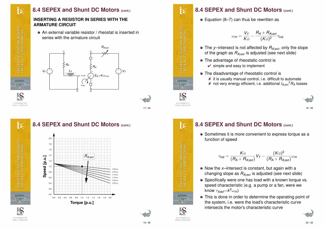
INSERTING A RESISTOR IN SERIES WITH THEARMATURE CIRCUIT
An external variable resistor / rheostat is inserted inseries with the armature circuit
A2
−EA=Kφωm
+
RA
A1
ωm
F2
−LF
+
RF
F1
φ =⇒−+VF −
+ VT
RA|ext
17 / 48
8.4 SEPEX and Shunt DC Motors (cont.)
Equation (8–7) can thus be rewritten as
ωm =VT
Kφ−
RA + RA|ext
(Kφ)2 τind
The y–intersect is not affected by RA|ext , only the slopeof the graph as RA|ext is adjusted (see next slide)
The advantage of rheostatic control is4 simple and easy to implement
The disadvantage of rheostatic control is8 it is usually manual control, i.e. difficult to automate8 not very energy efficient, i.e. additional IA|ext
2RA losses
18 / 48
8.4 SEPEX and Shunt DC Motors (cont.)
0.00 p.u.
0.05 p.u.
0.10 p.u.
0.15 p.u.
0.20 p.u.
0.25 p.u.
0.0 0.2 0.4 0.6 0.8 1.0 1.2 1.4 1.6 1.8 2.0
0.0
0.2
0.4
0.6
0.8
1.0
1.2
1.4
1.6
1.8
2.0
Torque [p.u.]
Spe
ed[p
.u.] RA|ext
19 / 48
8.4 SEPEX and Shunt DC Motors (cont.)
Sometimes it is more convenient to express torque as afunction of speed
τind =Kφ
(RA + RA|ext)VT −
(Kφ)2
(RA + RA|ext)ωm
Now the x–intersect is constant, but again with achanging slope as RA|ext is adjusted (see next slide)Specifically were one has load with a known torque vs.speed characteristic (e.g. a pump or a fan, were weknow τload=k2ωm)This is done in order to determine the operating point ofthe system, i.e. were the load’s characteristic curveintersects the motor’s characteristic curve
20 / 48
8.4 SEPEX and Shunt DC Motors (cont.)
0.00
p.u.
0.05
p.u.
0.10
p.u.
0.15
p.u.
0.20
p.u.
0.25
p.u.
0.0 0.2 0.4 0.6 0.8 1.0 1.2 1.4 1.6 1.8 2.0
0.0
0.2
0.4
0.6
0.8
1.0
1.2
1.4
1.6
1.8
2.0
Speed [p.u.]
Torq
ue[p
.u.]
RA|ext
21 / 48
8.4 SEPEX and Shunt DC Motors (cont.)
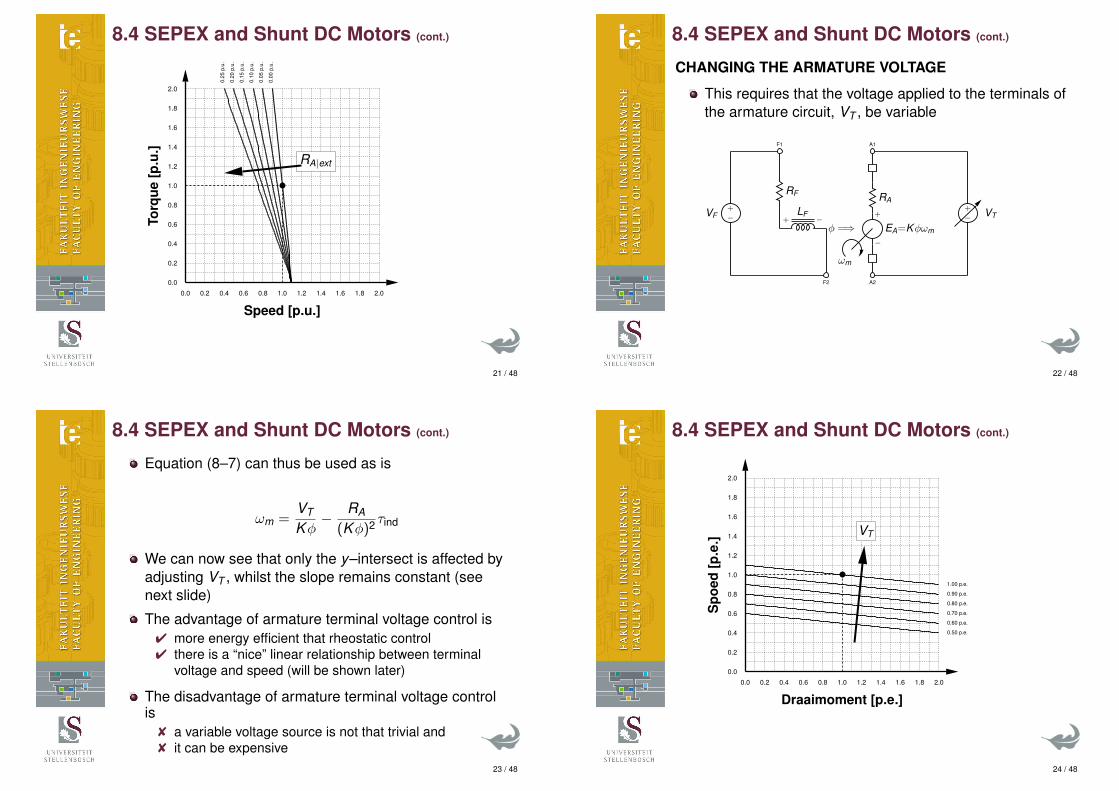
CHANGING THE ARMATURE VOLTAGE
This requires that the voltage applied to the terminals ofthe armature circuit, VT , be variable
A2
−EA=Kφωm
+
RA
A1
ωm
F2
−LF
+
RF
F1
φ =⇒−+VF −
+ VT
22 / 48
8.4 SEPEX and Shunt DC Motors (cont.)
Equation (8–7) can thus be used as is
ωm =VT
Kφ− RA
(Kφ)2 τind
We can now see that only the y–intersect is affected byadjusting VT , whilst the slope remains constant (seenext slide)
The advantage of armature terminal voltage control is4 more energy efficient that rheostatic control4 there is a “nice” linear relationship between terminal
voltage and speed (will be shown later)
The disadvantage of armature terminal voltage controlis
8 a variable voltage source is not that trivial and8 it can be expensive
23 / 48
8.4 SEPEX and Shunt DC Motors (cont.)
0.50 p.e.
0.60 p.e.
0.70 p.e.
0.80 p.e.
0.90 p.e.
1.00 p.e.
0.0 0.2 0.4 0.6 0.8 1.0 1.2 1.4 1.6 1.8 2.0
0.0
0.2
0.4
0.6
0.8
1.0
1.2
1.4
1.6
1.8
2.0
Draaimoment [p.e.]S
poed
[p.e
.]
VT
24 / 48
8.4 SEPEX and Shunt DC Motors (cont.)
Again sometimes it is more convenient to expresstorque as a function of speed
τind =KφRA
VT −(Kφ)2
RAωm
We can now see that only the x–intersect is affected byadjusting VT , whilst again the slope remains constant(see next slide)
25 / 48
8.4 SEPEX and Shunt DC Motors (cont.)
0.5
p.e.
0.6
p.e.
0.7
p.e.
0.8
p.e.
0.9
p.e.
1.0
p.e.
0.0 0.2 0.4 0.6 0.8 1.0 1.2 1.4 1.6 1.8 2.0
0.0
0.2
0.4
0.6
0.8
1.0
1.2
1.4
1.6
1.8
2.0
Spoed [p.e.]
Dra
aim
omen
t[p.
e.]
VT
26 / 48
8.4 SEPEX and Shunt DC Motors (cont.)
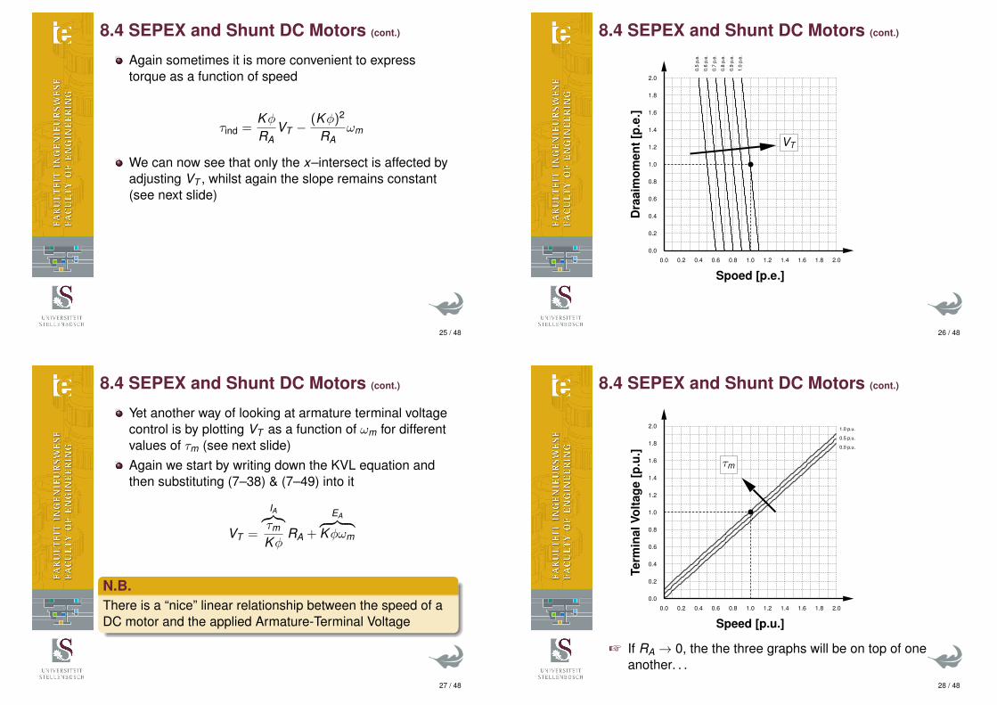
Yet another way of looking at armature terminal voltagecontrol is by plotting VT as a function of ωm for differentvalues of τm (see next slide)Again we start by writing down the KVL equation andthen substituting (7–38) & (7–49) into it
VT =
IA︷︸︸︷τm
KφRA +
EA︷ ︸︸ ︷Kφωm
N.B.There is a “nice” linear relationship between the speed of aDC motor and the applied Armature-Terminal Voltage
27 / 48
8.4 SEPEX and Shunt DC Motors (cont.)
0.0 p.u.
0.5 p.u.
1.0 p.u.
0.0 0.2 0.4 0.6 0.8 1.0 1.2 1.4 1.6 1.8 2.0
0.0
0.2
0.4
0.6
0.8
1.0
1.2
1.4
1.6
1.8
2.0
Speed [p.u.]Te
rmin
alVo
ltage
[p.u
.]
τm
+ If RA → 0, the the three graphs will be on top of oneanother. . .
28 / 48
8.4 SEPEX and Shunt DC Motors (cont.)
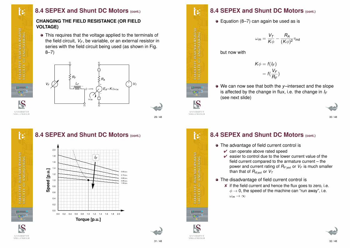
CHANGING THE FIELD RESISTANCE (OR FIELDVOLTAGE)
This requires that the voltage applied to the terminals ofthe field circuit, VF , be variable, or an external resistor inseries with the field circuit being used (as shown in Fig.8–7)
A2
−EA=Kφωm
+
RA
A1
ωm
F2
−LF
+
RF
F1
φ =⇒−+VF −
+ VT
29 / 48
8.4 SEPEX and Shunt DC Motors (cont.)
Equation (8–7) can again be used as is
ωm =VT
Kφ− RA
(Kφ)2 τind
but now with
Kφ = f (IF )
= f (VF
RF)
We can now see that both the y–intersect and the slopeis affected by the change in flux, i.e. the change in IF(see next slide)
30 / 48
8.4 SEPEX and Shunt DC Motors (cont.)
1.00 p.u.0.90 p.u.
0.80 p.u.
0.70 p.u.
0.60 p.u.
0.0 0.2 0.4 0.6 0.8 1.0 1.2 1.4 1.6 1.8 2.0
0.0
0.2
0.4
0.6
0.8
1.0
1.2
1.4
1.6
1.8
2.0
Torque [p.u.]
Spe
ed[p
.u.]
IF
31 / 48
8.4 SEPEX and Shunt DC Motors (cont.)
The advantage of field current control is4 can operate above rated speed4 easier to control due to the lower current value of the
field current compared to the armature current – thepower and current rating of RF |ext or VF is much smallerthan that of RA|ext or VT
The disadvantage of field current control is8 if the field current and hence the flux goes to zero, i.e.φ→ 0, the speed of the machine can “run away”, i.e.ωm →∞
32 / 48

8.4 SEPEX and Shunt DC Motors (cont.)
Again sometimes it is more convenient to expresstorque as a function of speed
τind =KφRA
VT −(Kφ)2
RAωm
but again now with
Kφ = f (IF )
= f (VF
RF)
We can again now see that both the y–intersect and theslope is affected by the change in flux, i.e. the change inIF (see next slide)
33 / 48
8.4 SEPEX and Shunt DC Motors (cont.)
1.0
p.u.
0.9
p.u.
0.8
p.u.
0.7
p.u.
0.6
p.u.
0.0 0.2 0.4 0.6 0.8 1.0 1.2 1.4 1.6 1.8 2.0
0.0
0.2
0.4
0.6
0.8
1.0
1.2
1.4
1.6
1.8
2.0
Speed [p.u.]
Torq
ue[p
.u.] IF
34 / 48
8.4 SEPEX and Shunt DC Motors (cont.)
TORQUE AND POWER LIMITS OF A DC MOTOR
In all the graphs shown in die previous slides, therewere a “dot” in the middle. . .This is the rated operating point of the DC machine
Which occurs when,4 the rated terminal voltage is applied,4 the rated field current is drawn and4 the rated armature current is drawn,
So that the DC machine will be+ developing its rated torque and+ developing its rated power and+ running at rated (or base) speed
35 / 48
8.4 SEPEX and Shunt DC Motors (cont.)
Below rated / base speed, speed control is done byarmature terminal voltage controlarmature external resistance (rheostatic) control
Above rated / base speed, speed control is done byfield current control
Electrical motors different somewhat from InternalCombustion Engines (ICEs) in terms of their
“maximum developed torque” and“maximum developed power”
Defined in Chapman as
τmax = KφIA|max (8–14)
and
Pmax = τmaxωm (8–15)
36 / 48

8.4 SEPEX and Shunt DC Motors (cont.)
I prefer (and it is less confusing) to rather refer to it asrated torque and rated speed. . .So that I would redefine (8–14) & (8–15) to
τrated = KφIA|rated (8–14’)
and
Prated = τratedωm|rated (8–15’)
The interesting thing about electrical motors is that itcan develop more than its rated torque. . .It however implies that more than the rated armaturecurrent needs to be drawn. . .Which could result in the motor burning out . . .
37 / 48
8.4 SEPEX and Shunt DC Motors (cont.)
For an ICE, this is not possible
Diesel Engine
PM Alternator
2,000-3,600 r/min Three Phase, 250-450 Vac
Diode Rectifier/
Boost Converter
350-450 Vdc Selectable Output Inverter
50/60/400 Hz
Common Mode and Transverse Mode Filter
120 Vac, Single Phase 120/240 Vac, Dual Phase 120/208 Vac Three Phase
Bidirectional Buck/Boost Converter
28 Vdc
28 Vdc Auxiliary Loads
Two 12-V Batteries in
Series
Power Supply for Controller and Power Electronics
1
Functional block diagram of power conversion components in generator set.
conditions. It is also possible to control the engine to run where it is most audibly quiet, at its least-polluting operating point (from an emissions point of view), or at its most reliable, stiffest point such that it is less sensitive to load transients. This article describes a proof-of-concept development for a 7.5-kW gen-set in a family of military gen-sets in the 5- to 60-kW range.
Gen-Set Operation A block diagram of the electronic power conversion system for the proof-of-concept gen-set developed at the Oak Ridge National Laboratory (ORNL) is shown in Figure 1 [6], [7]. The military gen-set uses an internal combustion (IC) diesel engine to drive a radial-gap permanent magnet (PM) alternator at variable speed. The speed of the engine is determined from a user-selectable interface that allows the engine to run at its most efficient operating point for a given load and ambient thermal conditions. The variable frequency, variable voltage produced by the PM alternator is diode-rectified to dc voltage, and an inverter is used to produce selectable-frequency, controllable ac voltage.
The user is allowed to select single-phase 120-V, dual-phase 120/240-V, or three-phase 120/208-V. Each of these voltage configurations can be generated at 50, 60, and 400 Hz such that the unit can be compatible with equipment produced from around the world or for aerospace applications. The power-conversion system also incorporates a bidirectional dc-dc converter that can charge 24-V batteries that are used to start the IC engine and to power auxiliary loads [8]. The converter can also draw power from the batteries to help maintain the dc link during severe load transients.
Engine and Alternator Description Each gen-set size was determined by selecting an advanced diesel engine that had a high power-to-weight ratio. For the smallest gen-set, an air-cooled Ruggerini MD 191 rated at 13 kW was used as the prime mover. The engine
Torq
ue (
N m
) or
Pow
er (
kW)
⋅
Engine Speed (r/min)
Fue
l Con
sum
ptio
n (k
g/kW
h)
50 45 40 35 30 25 20 15 10
5 0 1,800 2,200 2,600 3,000 3,400 3,800
0.40 0.38 0.36 0.34 0.32 0.30 0.28 0.26 0.24 0.22 0.20
Torque
Fuel Consumption
Power
2
Peak torque, power, and fuel consumption for the diesel
engine in the proof-of-concept gen-set.
3
PM alternator mounted to gen-set engine. 49
IEE
E IN
DU
ST
RY
AP
PL
ICA
TIO
NS
MA
GA
ZIN
E •
M
AR
|A
PR
20
03
•
WW
W.IE
EE
.OR
G/
IAS
38 / 48
8.4 SEPEX and Shunt DC Motors (cont.)
For a DC motor, the maximum (or rated) torque–speedand power–speed curves, looks as follows
39 / 48
8.4 SEPEX and Shunt DC Motors (cont.)
+ Below rated / base speed,Ê the applied armature terminal voltage increases linearly
with speed,Ë but the armature current can be at its maximum / rated
value, even from standstillÌ thus the maximum power increases linearly with speedÍ where as the maximum torque the DC motor can
develop will be constant
+ Above rated / base speed,Ê the applied armature terminal voltage can’t increase any
more,Ë neither can the armature current,Ì thus the maximum power stays constant (it can’t
increase)Í and hence the maximum torque the DC motor can
develop, will decrease hyperbolically (k = xy )
40 / 48

8.5 The Permanent-Magnet DC Motor
A Permanent-Magnet (PM) DC motor uses PMs togenerate the flux in the motorThus the flux is fixed and hence Kφ is constantFor PM DC motors, manufacturers sometimes refer toKφ as motor or machine constant, Km
Advantages of PM DC Motors arewe don’t have to worry about the fieldKm = Kφ = constant
Disadvantages of PM DC Motors arePM DC motors are expensivewe can’t operate the PM DC motor above rated speedbecause we can’t reduce the flux in the machine
Ignore rest of this section. . .
41 / 48
8.8 DC Motor Starters
From the KVL equation for the armature circuit,
IA =VT − EA
RA
We can see that at start-up,the speed ωm=0, and thus the back-EMF, EA=0coupled with the fact that armature resistance, RA, isusually very smallwe can see that the armature current, IAand hence the torque developed at standstill, τind, will beextremely high
+ which could lead to “something breaking” on themechanical side
Hence a starting resistor in series with armature circuitor a lower starting armature terminal voltage is required
Ignore rest of this section. . .42 / 48
8.10 DC Motor Efficiency Calculations
+ Have a look again at Chapman Section 7.7
The efficiency of a DC motor at a certain operatingpoint, is given by
η =Pout
Pin× 100%
=Pconv − Pno-load
Parmature + Pfield× 100%
=(τind − bωm)ωm
VT IA + VF IF× 100%
+ Don’t forget about the losses in the field winding. . .+ Chapman doesn’t calculate the viscous friction
coefficient, b, and assumes the no-load losses(Pmech + Pcore) stays constant and is not affected byspeed
43 / 48
8.11 Introduction to DC Generators
For DC motor, speed regulation is important, but for aDC generator (similar to a transformer) voltageregulation (VR) is important
VR =Vnl − Vfl
Vfl× 100% (8–39)
with nl ≡ no-load & fl ≡ full-load
The different types of DC generators that exist are:Ê separately excitedË shuntÌ permanent-magnetÍ seriesÎ cumulatively compoundÏ differential compound
44 / 48
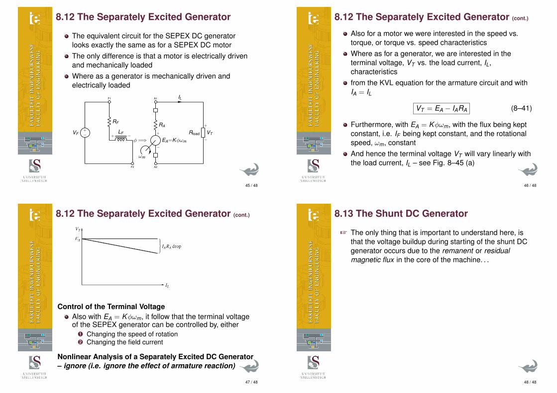
8.12 The Separately Excited Generator
The equivalent circuit for the SEPEX DC generatorlooks exactly the same as for a SEPEX DC motorThe only difference is that a motor is electrically drivenand mechanically loadedWhere as a generator is mechanically driven andelectrically loaded
A2
−EA=Kφωm
+
RA
A1
ωm
F2
−LF
+
RF
F1
φ =⇒−+VF Rload
−VT
+
IL
45 / 48
8.12 The Separately Excited Generator (cont.)
Also for a motor we were interested in the speed vs.torque, or torque vs. speed characteristicsWhere as for a generator, we are interested in theterminal voltage, VT vs. the load current, IL,characteristicsfrom the KVL equation for the armature circuit and withIA = IL
VT = EA − IARA (8–41)
Furthermore, with EA = Kφωm, with the flux being keptconstant, i.e. IF being kept constant, and the rotationalspeed, ωm, constantAnd hence the terminal voltage VT will vary linearly withthe load current, IL – see Fig. 8–45 (a)
46 / 48
8.12 The Separately Excited Generator (cont.)
Control of the Terminal VoltageAlso with EA = Kφωm, it follow that the terminal voltageof the SEPEX generator can be controlled by, either
Ê Changing the speed of rotationË Changing the field current
Nonlinear Analysis of a Separately Excited DC Generator– ignore (i.e. ignore the effect of armature reaction)
47 / 48
8.13 The Shunt DC Generator
+ The only thing that is important to understand here, isthat the voltage buildup during starting of the shunt DCgenerator occurs due to the remanent or residualmagnetic flux in the core of the machine. . .
48 / 48