electrical control and protection system of geothermal power plants
22
Orkustofnun, Grensasvegur 9, Reports 2014 IS-108 Reykjavik, Iceland Number 13 187 ELECTRICAL CONTROL AND PROTECTION SYSTEM OF GEOTHERMAL POWER PLANTS Daniel Gorfie Beyene Ethiopian Electric Power Company P.O. Box 1233 Addis Ababa ETHIOPIA [email protected] ABSTRACT This study explores the use of electrical controls and a protection system in a geothermal power plant for smooth and reliable operation of the plant. Geothermal power is a renewable energy and is also used as a baseload for the supply of electricity in the grid. To fulfil this goal, great measures must be taken in the selection of electrical protection equipment for the different electrical components, such as the transformer and the generator, as described in the report. A geothermal power plant must also be furnished with a proper control system for controlling different components of the plant such as the turbine, the generator, the transformer, the excitation system and other related accessories so that when some abnormal condition occurs in the system, proper action can be taken. 1. INTRODUCTION Energy is one of the most fundamental elements of our universe. The significance of energy is especially vital for developing countries like Ethiopia. On-demand energy in the form of electricity and modern fuels is the lifeblood of modern civilization and is a critical factor for economic development and employment. In 2013, the total installed capacity of electrical power in Ethiopia was more than 2,200 MW, mainly from hydro power plants, with some help from wind and a small pilot geothermal power plant. Ethiopia launched a long-term geothermal exploration undertaking in 1969. Over the years, a good inventory of the potential target areas has been built up and a number of the more important sites have been explored. About 16 geothermal prospects are judged as having potential for electricity generation. A much larger number could be developed for applications in agriculture, agro-industry, etc. Ethiopia could generate a huge amount of energy from geothermal resources, both for local consumption and export. However, an important constraint for this is the lack of finances. On this point, the government is considering various options that could help develop the resource while reviewing the overall energy policy of the country. One option is to invite private investors to participate in the geothermal resource utilization sector, like the Corbetti geothermal power plant project which is planned to be totally built by the private sector.
-
Upload
nguyentuong -
Category
Documents
-
view
212 -
download
0
Transcript of electrical control and protection system of geothermal power plants

Orkustofnun, Grensasvegur 9, Reports 2014 IS-108 Reykjavik, Iceland Number 13
187
ELECTRICAL CONTROL AND PROTECTION SYSTEM OF GEOTHERMAL POWER PLANTS
Daniel Gorfie Beyene Ethiopian Electric Power Company
P.O. Box 1233 Addis Ababa ETHIOPIA
ABSTRACT
This study explores the use of electrical controls and a protection system in a geothermal power plant for smooth and reliable operation of the plant. Geothermal power is a renewable energy and is also used as a baseload for the supply of electricity in the grid. To fulfil this goal, great measures must be taken in the selection of electrical protection equipment for the different electrical components, such as the transformer and the generator, as described in the report. A geothermal power plant must also be furnished with a proper control system for controlling different components of the plant such as the turbine, the generator, the transformer, the excitation system and other related accessories so that when some abnormal condition occurs in the system, proper action can be taken.
1. INTRODUCTION Energy is one of the most fundamental elements of our universe. The significance of energy is especially vital for developing countries like Ethiopia. On-demand energy in the form of electricity and modern fuels is the lifeblood of modern civilization and is a critical factor for economic development and employment. In 2013, the total installed capacity of electrical power in Ethiopia was more than 2,200 MW, mainly from hydro power plants, with some help from wind and a small pilot geothermal power plant. Ethiopia launched a long-term geothermal exploration undertaking in 1969. Over the years, a good inventory of the potential target areas has been built up and a number of the more important sites have been explored. About 16 geothermal prospects are judged as having potential for electricity generation. A much larger number could be developed for applications in agriculture, agro-industry, etc. Ethiopia could generate a huge amount of energy from geothermal resources, both for local consumption and export. However, an important constraint for this is the lack of finances. On this point, the government is considering various options that could help develop the resource while reviewing the overall energy policy of the country. One option is to invite private investors to participate in the geothermal resource utilization sector, like the Corbetti geothermal power plant project which is planned to be totally built by the private sector.

Daniel Gorfie 188 Report 13 In the above perspective, the government is planning to increase the country’s power generation capacity by developing the identified geothermal resources in the prospect areas. The Aluto-Langano geothermal power plant is located 200 km south of Addis Ababa and started operation in 1998. Two generation units can supply 7.28 MW in total, about 3.5 MW each. There are two types of turbines: one is a high-temperature vapour type that revolves the generator directly (6,000 rounds/min); the other is a media (isopentane/isobutane) turbine with heated by middle-temperature vapour heating the media to revolve the generator (1,500 rounds/min). This report mainly focusses on the electrical controls and protection system for a geothermal power plant, with emphasis on how the control system and various electrical protective relay schemes could be integrated to provide reliable operation of the Aluto-Langano geothermal power plant. 2. OVERVIEW OF GEOTHERMAL POWER PLANTS The basic types of geothermal power plants in use today are steam condensing turbines and binary cycle units. Steam condensing turbines can be used either in flash or dry-steam plants operating at sites with intermediate- and high-temperature resources (≥150°C). The power plant generally consists of pipelines, water-steam separators, vaporizers, de-misters, heat exchangers, turbine generators, cooling systems, and a step-up transformer for transmission into the electrical grid. Binary-cycle plants, typically organic Rankine cycle (ORC) units, are commonly installed to extract heat from low-temperature geothermal fluids (generally from 70 to 170°C) derived from hydrothermal and enhanced geothermal system type reservoirs. Binary plants are more complex than condensing ones since the geothermal fluid (water, steam or both) passes through a heat exchanger for heating another working fluid. This working fluid, such as isopentane or isobutene with a low boiling point, vaporizes, drives a turbine, and is then air cooled or condensed with water, as shown in Figure 1. Binary plants are often constructed as linked modular units of a few MW in capacity. There are also combined or hybrid plants, which comprise two or more of the above basic types, such as using a binary plant as a bottoming cycle with a flash steam plant, to improve versatility, increase overall thermal efficiency, improve the load-following capability, and efficiently cover a wide resource temperature range.
FIGURE 1: A schematic diagram showing the basic concept of a low-temperature geothermal binary ORC system for electrical power
generation (Ismail, 2013)

Report 13 189 Daniel Gorfie 2.1 Binary cycle power plants The binary cycle power plant uses an organic working fluid instead of steam (geothermal fluids). In this system the primary fluid (brine) is extracted from the low-temperature (intermediate-temperature) geothermal resource from the production well. Figure 1 shows the principal elements of this type of plant. The primary (reservoir) fluid carries the heat and efficiently transfers this heat to the low-boiling-point working fluid, using an effective heat exchanger. The organic fluid is then condensed in a similar manner to the steam in the flash power plant, except that a shell and tube type condenser rather than direct contact is used. The fluid in a binary plant is recycled back to the heat exchanger and forms a closed loop. The cooled reservoir fluid is again re-injected back into the reservoir. A binary cycle plant typically varies in size from 500 kW to 25 MW. 3. MAIN ELECTRICAL COMPONENTS OF A GEOTHERMAL POWER PLANT In geothermal power plants the steam rotates a turbine that activates a generator, which produces electricity. In order to make the electricity production feasible, many electrical and mechanical components are needed, as shown in Figure 2.
3.1 Generator The generator is an electro-mechanical device that converts mechanical energy to alternating current electrical energy. The generator is composed of four basic components: the shaft, the exciter, the rotor and the stator. The turning of the turbines powers the exciter to send an electrical current to the rotor.
FIGURE 2: Main electrical, control and instrumentation parts of a geothermal power plant (ABB, 2014)

Daniel Gorfie 190 Report 13 Generators appear in a number of sizes, ranging from less than 1 MW (typically in a cogeneration plant) to 600 MW. Generated voltages are generally constrained in the range of 6.6 kV to 33 kV due to design limitations in the generator insulation systems. This means that step-up transformers are generally needed to connect the generator to the transmission system or grid. 3.2 Generator excitation system The main functions of the excitation system are to provide a variable DC current to the field winding for controlling terminal voltage with suitable accuracy, ensure stable operation with the network and/or other machines, contribute to transient stability subsequent to a fault, communicate with the power plant control system and keep the machinery within permissible operating ranges. 3.3 Governor system The governor system is a vital control system in a geothermal power plant as it regulates the steam turbine speed, power and regulation of the grid frequency in response to control signals such as speed error and power error compared to the desired values. This action takes place in a closed loop control
system in which control action goes on till the power mismatch is reduced to zero. The governor system, as shown in Figure 3, receives speed and power signals that are then compared with the reference values and adjusts them to the desired values. Control valve (CV) is a hydraulic valve used for automatic control of fluid flow in response to a command from the governing system. If the steam pressure is below the
predefined level, the governor system sends a command signal to close the control valve. The four main functions of the governing system are as follows:
a) Emergency: To limit or control the speed rise to an acceptable limit upon a load rejection (when the unit is suddenly disconnected from the load).
b) Turbine: To control the power that is generated by controlling the position of the steam governing valve.
c) Start-up and stop: To control the speed of the turbo generator during initial run-up and synchronization.
d) Normal operation: To match the power and participate in the control of system frequency. It is mainly divided into:
i. Pressure control for constant steam pressure (maximum power) ii. Power control for constant output power
FIGURE 3: Steam turbine governing scheme

Report 13 191 Daniel Gorfie 3.4 Power transformer The power transformer transforms the voltage from the generator to a high voltage necessary for transmission over the utility’s electricity grid (transmission network). Depending on the size of the system, transmission voltages will range from 33 kV to 500 kV. Limitations on the insulation design which can be achieved on rotating machinery prohibit the generator from producing high voltage without the use of a step-up transformer (Fassbinder 1997). The power transformer (Figure 4) must fit the generator so that the transformer can totally utilize the generator´s active and reactive power capacity. The standard C57.116-1989 IEEE Guide for Transformers Directly Connected to Generator describes how this characteristic must be matched to the situation (ABB, 2004):
Transformer MVA rating; Short circuit impedance of the transformer; The secondary (high-voltage ) rating; The primary (low-voltage) rating.
3.5 Station start-up transformer The station start-up transformer is a power transformer (usually 400V AC secondary voltage) used to connect the power station to the transmission system so that power is available for the plant equipment when the plant is being started. Power plants are routinely brought down for servicing of major pieces of equipment. Generally, this transformer is used whenever the station auxiliary transformer is unavailable such as during planned maintenance or repairs. 3.6 Station or unit auxiliary transformer The station or unit auxiliary transformer is connected to the generator output by a tap off of the isolated Phase Bus Duct. The high-voltage winding of the transformer is designed to match the generator output voltage and the low voltage is supplied for different pumps and other auxiliary systems in a power plant, shown in Figure 5. This transformer and the station start up transformer have to be specified and connected in a configuration so that the output voltage will be in phase. The unit auxiliary transformer is the normal power source for the station equipment when the plant is operating. Once the generator is
FIGURE 4: A power transformer
FIGURE 5: Single line diagram for a supply of a generation station’s auxiliary power

Daniel Gorfie 192 Report 13 brought on line and is connected to the transmission grid, the station load can be transferred from the start-up transformer. 3.7 Standby diesel generator The standby diesel generator is a vital electrical component in any power plant for delivering power to main components of the unit during start-up in the case of a total black-out in the system. The sequence of operations for delivering power to the auxiliary load is as follows:
a) Using the unit auxiliary transformer directly tapped from the unit; b) Using station service transformer tapped from the system or grid; c) Using standby diesel generator.
The rating of the standby diesel generator must supply most of the power consumed by auxiliary load for a short time when a black start of the plant is required. 3.8 Ventilation system
The ventilation system of a geothermal power plant is a mandatory process for the circulation of clean air in the power plant. It is used for the following:
Filtering of H2S; Circulating and cooling air in the control room; Cooling different electrical components such as excitation equipment and protection equipment; Discarding heat from the cooling unit to the atmosphere.
3.9 Auxiliary power consumption
The auxiliary power consumption is the electrical power needed to drive the pumps and fans that support the operation of a power plant. The power consumption of a geothermal power plant is high compared with other power plants, since the plant is comprised of different high rating motors for:
Cooling tower fans; Cooling pumps; Feed pumps; Air compressors Lube oil pump (hydraulic system); Fire water pump; Brine pump; Ventilation system.
As an example, the generated capacity of the Berlin binary geothermal power plant is 12.5 MVA and the total power consumed by pumps and fans is approximately 1.3 MVA, hence 10.4 % of the total power generated is consumed by the auxiliary load (ENEX, 2014). 3.10 DC auxiliary power system
The direct current system in thermal generating stations is provided for the following functions:
Report 13 193 Daniel Gorfie
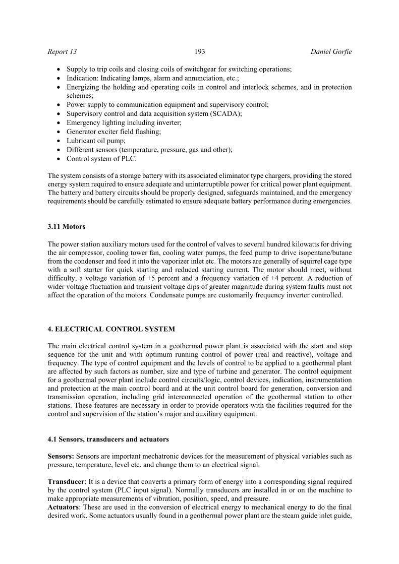
Supply to trip coils and closing coils of switchgear for switching operations; Indication: Indicating lamps, alarm and annunciation, etc.; Energizing the holding and operating coils in control and interlock schemes, and in protection
schemes; Power supply to communication equipment and supervisory control; Supervisory control and data acquisition system (SCADA); Emergency lighting including inverter; Generator exciter field flashing; Lubricant oil pump; Different sensors (temperature, pressure, gas and other); Control system of PLC.
The system consists of a storage battery with its associated eliminator type chargers, providing the stored energy system required to ensure adequate and uninterruptible power for critical power plant equipment. The battery and battery circuits should be properly designed, safeguards maintained, and the emergency requirements should be carefully estimated to ensure adequate battery performance during emergencies. 3.11 Motors
The power station auxiliary motors used for the control of valves to several hundred kilowatts for driving the air compressor, cooling tower fan, cooling water pumps, the feed pump to drive isopentane/butane from the condenser and feed it into the vaporizer inlet etc. The motors are generally of squirrel cage type with a soft starter for quick starting and reduced starting current. The motor should meet, without difficulty, a voltage variation of +5 percent and a frequency variation of +4 percent. A reduction of wider voltage fluctuation and transient voltage dips of greater magnitude during system faults must not affect the operation of the motors. Condensate pumps are customarily frequency inverter controlled. 4. ELECTRICAL CONTROL SYSTEM The main electrical control system in a geothermal power plant is associated with the start and stop sequence for the unit and with optimum running control of power (real and reactive), voltage and frequency. The type of control equipment and the levels of control to be applied to a geothermal plant are affected by such factors as number, size and type of turbine and generator. The control equipment for a geothermal power plant include control circuits/logic, control devices, indication, instrumentation and protection at the main control board and at the unit control board for generation, conversion and transmission operation, including grid interconnected operation of the geothermal station to other stations. These features are necessary in order to provide operators with the facilities required for the control and supervision of the station’s major and auxiliary equipment. 4.1 Sensors, transducers and actuators Sensors: Sensors are important mechatronic devices for the measurement of physical variables such as pressure, temperature, level etc. and change them to an electrical signal. Transducer: It is a device that converts a primary form of energy into a corresponding signal required by the control system (PLC input signal). Normally transducers are installed in or on the machine to make appropriate measurements of vibration, position, speed, and pressure. Actuators: These are used in the conversion of electrical energy to mechanical energy to do the final desired work. Some actuators usually found in a geothermal power plant are the steam guide inlet guide,

Daniel Gorfie 194 Report 13 Servo valve position controllers, Solenoid valves, and relays to open or close the circuit breaker.
The complete control drive of the system is shown in Figure 6; the sensor measure signals and sends a command to the controller to give the desired level of voltage and current to the actuator for the desired movement of the mechanical load. Different types of sensors (flammable gas detectors, pressure detectors, temperature detectors and level sensors) have to be placed on the main mechanical components of the
geothermal power plant such as the turbine, condenser, evaporator, valves and pipelines in order to take proper action before components suffer severe damage. 4.2 Conventional control system with relay logic (mechanical/analogue electronic governor) Control systems of the power plant are broadly classified under four main categories:
1. Manual control: Whereby each item in the prestart chain checks: starting, synchronizing, loading and stopping, and a sequence is selected and performed in turn by hand, whether mechanically or by push buttons.
2. Semi-automatic control: Whereby, from a single manual starting impulse, a unit may be brought to the ready to synchronise conditions by automatic selection, performance, and provision of a sequence of controls. Likewise, a similar stopping impulse completely shuts down the unit. Synchronizing and loading and running controls remain manual functions from the local and remote control points.
3. Fully automatic control: Whereby means are provided for running up, automatically synchronizing and loading up to a predetermined quantity on receipt of a single starting impulse. Subsequent manual variations of loading and excitation may be provided as a remote control function. The corresponding stopping impulse will cause the load to be reduced, the unit to be disconnected from the busbars and the turbine to be shut down completely.
4. Offsite supervisory control: Starting, stopping, switch closing or opening and other functions are initiated from a remote point, together with indications of successful operations of voltage and load control and of the repetition of alarm conditions at the remote control point.
4.3 Computer-based control of a geothermal power station Recent practice for controlling geothermal power plants is based on a combination of computer-based and non-computer-based equipment utilized for unit, plant and system control. Control of a power plant from local, centralized and offsite modes of operation and supervision are listed in Table 1. The control system receives input signals (status signals) from main equipment such as the turbine or the generator, and from various other accessory equipment, such as (temperature, pressure, and level), governor, exciter, and automatic synchronizer. Status inputs are obtained from control switches and level and function switches indicative of pressure, position, etc., throughout the plant. The proper combination of these inputs to the control system logic will provide outputs to the valves, motors, breakers, governor, the exciter, and other equipment to start or shut down the unit. Any abnormalities
Reference
Converter
Controller
Power Actuator Load
Position/ Velocity sensor
Current sensor
FIGURE 6: The composition of a controlled drive system
Report 13 195 Daniel Gorfie
TABLE 1: Summary of control hierarchy for electrical power plants
Control category Subcategory Remarks
Location Local
Control is local at the controlled equipment or within sight of the equipment
Centralized Control is remote from controlled equipment, but within plant Offsite Control location is remote from the project
Mode Manual
Each operation needs a separate and discrete initiation; could be applicable to any of the three locations
Automatic Several operations are precipitated by a single initiation; could be applicable to any of the three locations
Operation (supervision)
Attended Operator is available at all times to initiate control action Unattended Operation staff is not normally available at the project site
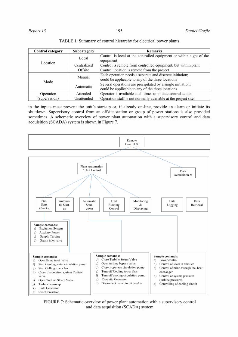
in the inputs must prevent the unit’s start-up or, if already on-line, provide an alarm or initiate its shutdown. Supervisory control from an offsite station or group of power stations is also provided sometimes. A schematic overview of power plant automation with a supervisory control and data acquisition (SCADA) system is shown in Figure 7.
FIGURE 7: Schematic overview of power plant automation with a supervisory control and data acquisition (SCADA) system
Plant Automation
/ Unit Control Data Acquisition &
Pre-Start
Checks
Automa-tic Start-
up
Automatic Shut-down
Unit Running Control
Monitoring &
Displaying
Data Logging
Sample comands: a) Excitation System b) Auxilary Power c) Supply Turbine d) Steam inlet valve
Data Retrieval
Sample comands: e) Open Brine inlet valve f) Start Cooling water circulation pump g) Start Colling tower fan h) Close Evaporation system Control
valve i) Open Turbine Steam Valve j) Turbine warm up k) Exite Generator a) Synchronisation
Sample comands: b) Close Turbine Steam Valve c) Open turbine bypass valve d) Close isoputane circulation pump e) Turn off Cooling tower fans f) Turn off cooling circulation pump g) De-exite Generator h) Disconnect main circuit breaker
Sample comands: a) Power control b) Control of level in reboiler c) Control of brine through the heat
exchanger d) Control of system pressure
(turbine pressure) e) Controlling of cooling circuit
Remote Control &

Daniel Gorfie 196 Report 13 4.4 PLC and SCADA system SCADA is a technology that enables a user to collect data from one or more distant facilities and/or send control instructions to the facilities. Modern control rooms utilize the far more cost-effective supervisory control and data acquisition (SCADA) systems, including programmable logic controllers (PLCs), and distributed computer control systems with graphic display screens, to implement a vast array of control schemes. The SCADA control scheme also provides flexibility in control, alarming, sequence of events recording, and remote communication that was not possible with the hardwired control systems (Figure 8).
The SCADA interface system allows operators to:
a) Start-stop the machinery and change the set point of the plant baseload; b) Obtain written reports of all parameters about the power plant; c) Monitor the plant status and control the alarm summery, events and analyse them.
FIGURE 8: SCADA system hardware with PLC controller (Ormat, 1997)

Report 13 197 Daniel Gorfie
The control system of a geothermal power plant has a big role in the smooth operation of unit start-up and shut down, summarized in Figure 9. 5. SYNCHRONIZING Before connecting a generator in parallel with other machines, it is necessary to prove that the incoming machine and the running system have the same frequencies and voltages, and are in phase. The methods employed in electric power stations are described below. Manual synchronizing: In this method, incandescent lamps are connected across the respective phases of the incoming and running voltage buses. Voltage of the incoming machine is matched with the system voltage by manually adjusting the excitation of the machine. The frequency and phase angle differences are indicated by lamps. Lamps will flicker with a frequency equal to the difference between the frequencies of incoming machinery and the running system. When the phase and frequencies are matched, the lamps will extinguish. This is the indication of synchronism of the machine with the system. The breaker is then closed manually. Manual synchronizing is simple and cheap. This requires personal supervision and the judgment of the operator. This type of synchronization is not suited for automatic or remote control of the unit. However, this has normally been provided as a standby in power stations for use in case of failure of the automatic/synchronizing equipment. Automatic synchronizing: Synchronizing equipment (Figure 10) performs the following functions automatically:
i. It continuously controls the terminal voltage of the incoming machinery until it is almost equal to the voltage of the system to which it is to be connected;
ii. It controls the speed of the prime mover so that the frequency difference is within the predetermined value;
iii. It energizes the closing coil of the circuit breaker associated with the incoming machinery at an instant when the phase difference between the two sources is sufficiently small and only when conditions (i) and (ii) have been simultaneously satisfied.
Plant in off position / Geothermal well
closed
Warming up of main stream
pipe line
Open well head master
valve
Warming up turbine parts
Turbine start up
Synchronization to the grid
Loading
FIGURE 9: Start-up sequence of a geothermal power plant
FIGURE 10: Automatic synchronoscope

Daniel Gorfie 198 Report 13 6. ELECTRICAL PROTECTION SYSTEM Power system protection is the process of making the production, transmission, and consumption of electrical energy as safe as possible from the effects of failures and events that place the power system at risk. It is cost prohibitive to make power systems 100% safe or 100% reliable. Power system protection must determine from the measurements of currents and/or voltages whether the power system is operating correctly. Three elements are critical for protective relays to be effective: measurements, data processing, and control. The high costs associated with large generating and transforming plants accentuate the need for reliable, high speed schemes of protection to:
a) Minimise fault damage and so reduce the possible need to replace the plant (capital outlay); b) Reduce repair outage time and so minimise the need to run a lower merit (less cost-efficient) plant
in order to meet the demand (revenue expenditure); c) Assist in maintaining system stability.
6.1 Main components of protection systems The main components of protection systems are discussed briefly below.
Current & voltage transformers, also called instrument transformers. Their purpose is to step down the current or voltage of a device to measurable values, within the instrumentation measurement range 5 A or 1 A in the case of current transformers (CTs), and 110 V or 100 V in the case of voltage (or potential) transformers (VTs/ PTs). Hence, protective equipment inputs are standardized within the ranges above.
Protective relays are intelligent electronic devices (IEDs) which receive measured signals from the secondary side of CTs and VTs and detect whether the protected unit is in a stressed condition (based on their type and configuration) or not. A trip signal is sent by protective relays to the circuit breakers to disconnect the faulty components from the power system if necessary (Reimert, 2006).
Circuit breakers act upon open commands sent by protective relays when faults are detected and upon close commands when faults are cleared. They can also be manually opened, for example, to isolate a component for maintenance.
6.2 Generator protection Power station generators should be protected against mechanical, electrical, and thermal damage that may occur as a result of abnormal conditions in the plant or in the utility system to which the plant is electrically connected. The protection of a generator presents a very challenging problem because of its system connections on three different sides, as shown Figure 11. On one side, it is connected to the prime mover; on the other side, it has to run in synchronism with the grid. On yet another (third) side, it is connected to the source of DC excitation. Thus, it is obvious that generator protection is very complex compared to protection for other elements of the power system. If there is a fault on a steam generator, it is not enough to open the main circuit breaker connecting it to the power grid; the following must be done as well:
Steam supply to the turbine is stopped or bypassed; Field circuit of the generator is interrupted; Field coils are connected across a resistor to dissipate the stored energy; Generator is kept running at a slow speed with the help of a barring gear till it cools down
uniformly, so as to avoid uneven expansions.

Report 13 199 Daniel Gorfie
Putting the generator back online is a rather slow process because all the parameters (temperature and pressure) have to be progressively built up to avoid thermal shock which would result in uneven expansion which, in turn, might cause unacceptable vibration. Therefore, an unscheduled outage of a geothermal power station is avoided as far as possible. 6.2.1 Generator faults
Stator faults: Stator faults involve the current carrying conductors and must be cleared quickly from the power system by a complete shutdown of the generator. There may be faults to earth, between phases or between turns of a phase, singly or in combination. The great danger from all faults is the possibility of damage to the insulation of the stator core and stator winding due to the heat generated at the point of the fault. Figure 12 shows the hierarchy of various electrical faults on a generator.
Phase-to-phase faults and inter-turn faults are both less common than earth faults. It is relatively easy to provide protection for phase-to-phase faults, but inter-turn faults are, on the other hand, more difficult to detect and protection is not usually provided. Generally, inter-turn faults quickly involve contact with earth via the stator core and are tripped by stator earth-fault protection. Rotor faults: The rotor carries the field winding which is kept isolated from the ground. Neither the positive nor the negative terminal of the dc supply is grounded. Thus, any ground fault on the rotor field winding does not affect the workings of the alternator. However, a subsequent fault would cause a section of the rotor winding to be short circuited, giving rise to a secondary flux which opposes the main flux in the proximity of the shorted turns, causing distortion in the distribution of the main flux. The flux will become concentrated on one pole but dispersed over the other and intervening surfaces. The
Generator Prime mover Power grid
DC excitation system
FIGURE 11: Principles of generator protection
Electrical faults
Rotor
Stator
Three-phase stator winding
Field winding
Inter-turn fault on the same phase
Ground fault
Phase fault
Short circuit to ground
FIGURE 12: Various electrical faults on a generator

Daniel Gorfie 200 Report 13
resulting asymmetry in the electromagnetic forces will cause severe vibrations of the rotor. In a modern generator, the inertia of rotation is very large and the rotor-to-stator clearances are very small, therefore, there is a likelihood of permanent damage to the turbo-alternator. In light of the above, the very first fault on the field winding must be detected and the set tripped in a controlled manner. An arrangement for rotor earth fault detection and protection is shown in Figure 13, wherein an external voltage source is superimposed on the rotor circuit. This external voltage source is grounded so that the very first rotor earth fault causes a dc fault current to flow, which is easily detected by an over current relay (Paithankar, and Bhide, 2003).
6.2.2 Abnormal operating conditions A generator cannot be considered in isolation because of the large number of other equipment connected to it. Even though there is no electrical fault in the generator, if one of its associated pieces of equipment develops a fault, then it has serious implications for the generator. Every auxiliary piece of equipment connected to the generator is a likely source of trouble. There are a large number of possible faults, as well as combinations of faults, on these pieces of equipment, that threaten the operation of the generator (Paithankar, and Bhide, 2003). Instances where there is no direct electrical fault in the generator but one or more of its associated pieces of equipment develops a fault or an abnormality may lead to an abnormal operating condition, which may or may not be serious. However, all abnormal operating conditions need to be detected as quickly and as sensitively as possible so that corrective action can be taken and a possible shutdown averted or anticipated. Some prominent abnormal operating conditions, shown in Figure 14, need to be carefully considered while providing protection to the generator: Over-speeding Assume that a power station generator is supplying its rated real electrical power Pe, to the grid. Its mechanical input Pm is nearly equal to Pe, (except for the losses) and the machine runs at constant synchronous speed Ns. If the generator is tripped due to some fault and disconnected from the grid, Pe becomes zero. However, the mechanical power input Pm cannot be suddenly reduced to zero. Therefore, it leads to a situation where the generator has full input mechanical power but no output electrical power (no load). This would cause the machine to accelerate to dangerously high speeds if the mechanical input is not quickly reduced by the speed-governing mechanism.
FIGURE 13: Rotor ground fault protection of generator by DC injection method

Report 13 201 Daniel Gorfie
The protection against such an eventuality can be provided by sensing the over-speeding and taking steps such as operating the steam valve so as to stop steam input to the turbine. The speed-governing mechanism or the speed governor of the turbine is basically responsible for detecting this condition. The over-speeding can also be detected either by an over-frequency relay or by monitoring the output of the tacho generator mounted on the generator shaft. The logic of protection against over-speeding is shown in Figure 15. Mechanical protection of genset A computerized vibration monitoring system supplies the information necessary to assess the mechanical condition of the rotary components of the genset (turbine/generator). A variety of supervisory parameters in x and y directions is continuously measured using the sensor attached the genset, as shown in Figure 16, and provides critical information on machinery problems such as imbalance, shaft misalignment, bent or cracked rotors, and bearing failure. The data is then fed to the control system, which can shut down the machinery in case of abnormal operations. Unbalanced loading If there is an unbalanced loading of the generator, then the stator currents have a negative sequence component. The stator field, due to these negative sequence currents, rotates at synchronous speed but in a direction opposite to the direction of the field structure on the rotor. Thus, the negative sequence stator armature magneto motive force (mmf) rotates at a speed -Ns while the rotor field speed is +Ns. Therefore, there is relative velocity between the two. This causes double frequency currents,
Mechanical
Abnormal operating Condition
Three-phase stator winding
Field winding
Electrical Unbalanced loading
Loss od excitation
Loss of prime mover
Over speed
FIGURE 14: Various abnormal operating conditions of a generator
Over-speed
Tackogenerator output
Over–frequency relay
Stop steam supply to turbine
Start shut down of generator
FIGURE 15: Protection against over-speeding
FIGURE 16: Genset vibration detector

Daniel Gorfie 202 Report 13 of large amplitude, to be induced in the rotor conductors and iron. Thus, if the stator carries unbalanced currents, then it is the rotor which is overheated. How long the generator can be allowed to run under unbalanced loading depends upon the thermal withstanding capacity of the machine. Loss of excitation There are several possible causes due to which field excitation may be lost, namely:
Loss of field to main exciter; Accidental tripping of the field breaker; Short circuit in the field winding; Poor brush contact in the exciter; Field circuit breaker latch failure; Loss of ac supply to excitation system.
Loss of prime mover With a loss of mechanical input, the generator continues to remain synchronized with the grid, running as a synchronous motor. The machine, now, draws a small amount of active power (compared to its rating) from the grid in order to drive the turbine and meet the losses taking place in the machine. At the same time, the machine supplies reactive power to the grid since its excitation is intact. Running in this mode is harmful to a prime mover like a steam turbine. When the machine runs as a motor, there is a churning of trapped steam in the turbine causing objectionable temperature rise and damage to the blades. Therefore, the loss of the prime mover needs quick detection followed by tripping of the generator, i.e. open generator switch. 6.3 Transformer protection Transformers are critical and expensive components of power systems like generators. Due to the long lead time for repair of and replacement of transformers, a major goal of transformer protection is limiting the damage to a faulted transformer. When a fault occurs in a transformer, the damage is proportional to the fault time. The transformer should, therefore, be disconnected as fast as possible from the network. Fast reliable protective relays are, therefore, used for detection of faults. The sizes of the transformer and the voltage level have influence on the extent and choice of protective equipment. Monitors prevent faults and protective relays limit the damage in case of a fault. The cost for the protective equipment is marginal compared to the total cost and the cost involved in case of a transformer fault. 6.3.1 Electrical protection Overcurrent protection: Overcurrent relays generally provide the same level of protection as power fuses. Higher sensitivity and fault clearing times can be achieved in some instances by using an overcurrent relay connected to measure the residual current. This application allows pick up settings to be lower than the expected maximum load current. It is also possible to apply an instantaneous overcurrent relay set to respond only to faults within the first 75% of the transformer. Overcurrent relays do not have the same maintenance and cost advantages found with power fuses. Protection and control devices, circuit breakers and station batteries are required. The overcurrent relays are a small part of the total cost and, when this alternative is chosen, differential relays are generally added to enhance transformer protection. In this instance, the overcurrent relays will provide backup protection for the differentials.

Report 13 203 Daniel Gorfie Differential protection: The most widely accepted device for transformer protection is called a restrained differential relay. This relay compares the current values flowing into and out of the transformer windings. To assure protection under varying conditions, the main protection element has a multislope restrained characteristic. The initial slope ensures sensitivity to internal faults while allowing for up to 15% mismatch when the power transformer is at the limit of its tap range (if supplied with a load tap changer). At currents above rated transformer capacity, extra errors may be gradually introduced as a result of CT saturation. Over-excitation: The flux level within a transformer is proportional to the voltage applied to the transformer and inversely proportional to the frequency of the applied voltage. When over-excitation conditions that are above transformer design limits occur, the transformer core becomes saturated, resulting in a build-up of heat with eventual damage to the transformer. Generator transformers are especially subject to over-excitation as such transformers are connected directly to the generator terminal s. Voltage and frequency conditions at the generator terminal s are subject to voltage and frequency variation s, especially during start-up of the generator. Over-excitation protection should be considered for all large transformers utilized as generator unit transformers, or those that are connected to portions of the power system conducive to causing transformers to become overexcited. Such protection should consist of relaying that is capable of directly responding to the level of excitation that exists such as volts/hertz relaying. Backup protection: Backup protection, typically overcurrent or impedance relays applied to one or both sides of the transformer, perform two functions. One function is to back up the primary protection, most likely a differential relay, and operate in the event of its failure to trip. The second function is protection for thermal or mechanical damage to the transformer. Protection that can detect these external faults and operate in time to prevent transformer damage should be considered. The protection must be set to operate before the through-fault withstanding capability of the transformer is reached. If, because of its large size or importance, only differential protection is applied to a transformer, clearing of external faults before transformer damage can occur by other protective devices must be ensured. 6.3.2 Mechanical protection There are several mechanical protection relays installed on the power transformer. The operation of these relays (listed below) is almost instantaneous (no time delay):
Buchholz relay; Winding temperature indicator; Oil temperature indicator and pressure relief.
All the above relays are operated mechanically and electrical circuit is needed for alarm and tripping circuits. A Buchholz relay is a protection device for monitoring the gas and oil movements in oil immersed transformers. It is used on practically all power transformers with the exception of small distribution sizes. In practice, it has proved to be the only protective device that can clear certain types of faults. The Buchholz relay relies on the principle that during fault conditions, gas is generated inside the transformer tank from the insulating oil. An example of a Buchholz relay device is shown in Figure 17 (Ahmed, 2005).
FIGURE 17: Buchholz relay

Daniel Gorfie 204 Report 13
Winding temperature indicator. A temperature indicator simulates the winding temperature. The temperature of the winding depends on the transformer load (i.e. the current through the winding) and the temperature of the cooling medium (oil). These two parameters are measured and made to interact in the instrument. The oil temperature is measured as usual with a bulb in a pocket. The measuring system also has a specially designed heating element to measure the transformer load. This heating element is a thermal model of the winding. The heating element is connected to the current transformer (CT) via a matching resistance or a matching unit to allow setting the correct winding temperature gradient. A sample of a winding temperature indicator is shown in Figure 18. An oil temperature indicator is similar to a winding temperature indicator except that it depends only on the temperature transferred by the bulb (no current transformer is used). A pressure relief valve is a device designed to protect a power transformer during an over-pressure event. An over-pressure event refers to any condition which could cause pressure in the transformer to increase beyond the specified design pressure. During internal faults of a
power transformer, there will be an increase in temperature associated with impurities in oil and some increase in pressure. This pressure is sufficient to damage the transformer. The pressure relief device is applied to prevent the transformer from this dangerous event. The pressure relief device consists of a spring which normally is uncompressed. When the pressure is increased in the transformer, the spring is compressed and provides a path for gases to exit the transformer. Compressing the spring may close an electrical contact, and this contact will trip circuit breakers associated with an alarm. Figure 19a shows the pressure relief device in normal condition (before a fault occurs), while Figure 19b shows the fault condition at which the compressed gases are released from the transformer.
FIGURE 18: Winding temperature indicator
FIGURE 19: Pressure relief, a) before fault occurrence; b) during fault
a) b)

Report 13 205 Daniel Gorfie 7. THE ALUTO-LANGANO GEOTHERMAL POWER PLANT ELECTRICAL SYSTEM 7.1 General The Aluto-Langano geothermal power plant is a pilot power plant in Ethiopia constructed by Ormat and started operation in 1998. The power plant is comprised of two power generation systems, the combined cycle steam (GCCU) and binary system (OEC). These units generate power of 11 KV which is supplied to the 11 KV main bus. 7.2 Generators The plant is composed of two power generating units. The GCCU consists of one 5.9 MVA generator driven by on steam turbine and one organic turbine. The OEC also consists of one 5.9 MVA generator driven by two organic turbines. A 375 KVA diesel generator was installed in the plant as a standby emergency power source to supply power to the main components of the power plant. 7.3 Transformers The transformers installed in the power plant are:
a) One step-up power transformer to convert the 11 KV power to the main bus to the 15 KV level of the grid.
b) Two auxiliary transformers which supply power to the loads of the OEC and GCCU units. Each one of the power generating units has a dedicated pad-mounted transformer of 11/0.4 KV (750 KVA and 1250 KVA).
c) One transformer having a capacity 400 KVA (11/0.4KV) which supplies power to the station’s auxiliary load distribution panel.
7.4 Protection systems
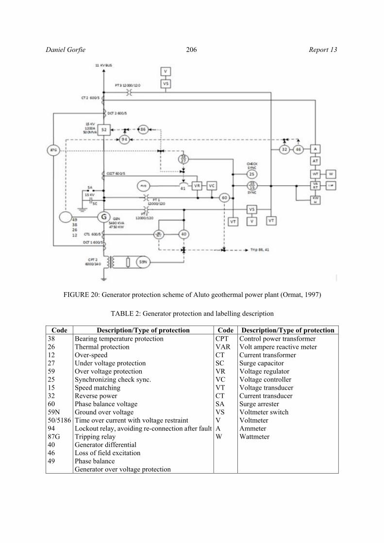
The main power transformer and generators are protected by the protection relays installed in the panel which, when activated, isolates the transformer and generator from the main bus and the grid by the circuit breaker, as shown in Figure 20 with explanations in Table 2. 7.5 Bus to grid synchronization
The following procedure (sequence of operation) is taken directly from the operating manual of Aluto geothermal power plant, prepared by the Ormat Company (Ormat, 1997):
a) Set the “ Bus Selector” switch at “BUS to GRID” position; b) By using selector “Speed”, the speed adjustment should be regulated (Raise/Slow) at a rate of
10 rpm/s; c) By using selector “Voltage”, bus voltage can be changed to much the grid voltage. d) Monitor generator parameters – frequency, voltage and synchronoscope. Adjust as per
paragraphs (c) and (d) to get the best matching. e) While synchronoscope is on zero and voltage and frequency of bus are matched to grid, push
“Synch Push Button” for two seconds. f) When synchronization is completed, turn bus selector to “OFF” position.
Daniel Gorfie 206 Report 13
TABLE 2: Generator protection and labelling description
Code Description/Type of protection Code Description/Type of protection
38 26 12 27 59 25 15 32 60 59N 50/5186 94 87G 40 46 49
Bearing temperature protection Thermal protection Over-speed Under voltage protection Over voltage protection Synchronizing check sync. Speed matching Reverse power Phase balance voltage Ground over voltage Time over current with voltage restraint Lockout relay, avoiding re-connection after faultTripping relay Generator differential Loss of field excitation Phase balance Generator over voltage protection
CPT VAR CT SC VR VC VT CT SA VS V A W
Control power transformer Volt ampere reactive meter Current transformer Surge capacitor Voltage regulator Voltage controller Voltage transducer Current transducer Surge arrester Voltmeter switch Voltmeter Ammeter Wattmeter
FIGURE 20: Generator protection scheme of Aluto geothermal power plant (Ormat, 1997)
Report 13 207 Daniel Gorfie 8. CONCLUSIONS The role of this project was to define an effective control and protection system for effective and reliable operation of a geothermal power plant. In order to deliver the power generated from the plant to the consumer, as well as operating the plant smoothly, special care is a must in the selection of a proper control and protection system. If a protection scheme does not operate correctly, the result can be extensive damage to the power equipment with consequent high repair cost and perhaps long average times. Hence, proper training should be conducted for power plant technicians and engineers who are responsible for installing, testing and calibrating the protection equipment. In order to make the geothermal power plant unattended or controlled at a distance, a modern control system must be installed. In addition to the working procedure of the SCADA system, a plant operator should also be equipped with basic software skills in case some problem happens in the software itself.
ACKNOWLEDGEMENTS I wish to express my sincere thanks to Mr. Lúdvík S. Georgsson, Director of UNU Geothermal Training Programme, for offering me the chance to participate in this training. I would also like to thank Mr. Ingimar G. Haraldsson, Ms. Málfrídur Ómarsdóttir, Ms. Thórhildur Ísberg and Mr. Markús A.G. Wilde for their kindness and efficient help during the training and for helpful guidance and support. I would like to respect and thank my supervisor, Mr. Bjarni Bjarnason, for his valuable guidance and kind supervision which made me complete the project on time and shaped the present work as presented. Finally, I wish also to thank all the other UNU Fellows during my time in the training period.
REFERENCES ABB, 2004: Transformer handbook. ABB group, Zurich, website: www.abb.com/transformer, 213 pp. ABB, 2014: Control system for steam and gas turbines. ABB group, Zurich, 70 pp. Ahmed, S.E., 2005: Practical introduction to power system protection and control. PIPSPC, 94 pp. ENEX, 2014: Binary geothermal power plant operation and instruction manual for 7.8 MW. ENEX, San Salvador. Fassbinder, S., 1997: Power generation. Energy efficient design of auxiliary systems in fossil-fuel power plants. ABB group, Zurich, 362 pp, webpage: www05.abb.com/global/scot/scot221.nsf/veritydisplay/5e627b842a63d389c1257b2f002c7e77/$file/Energy%20Efficiency%20for%20Power%20Plant%20Auxiliaries-V2_0.pdf. Ismail, B.I., 2013: ORC-based geothermal power generation and CO2-based EGS for combined green power generation and CO2 sequestration. In: Tech Open Publishing, website: www.intechopen.com. Ormat, 1997: Aluto geothermal power plant operation manual for 7.28 MW. Ormat Technologies, Ethiopia.

Daniel Gorfie 208 Report 13 Paithankar, Y.G., and Bhide, S.R., 2003: Fundamentals of power system protection. Prentice-Hall of lndia Private, Ltd., New Delhi, 301 pp. Reimert, D., 2006: Protective relaying for power generation systems. CRC Press, Taylor & Francis Group, 592 pp.