Electrical conductivity in thin films fabricated from ... · Electrical conductivity in thin films...
12
Materials Science-Poland, Vol. 27, No. 3, 2009 Electrical conductivity in thin films fabricated from nanoparticles of a polymeric composite based on PEDOT * D. RAIS 1** , J. HAIN 2 , A. PICH 2 , S. POCHEKAILOV 1 , S. NEŠPŮREK 1 , H.-J. P. ADLER 2 , A. HAMÁČEK 3 , J. ŘEBOUN 3 1 Institute of Macromolecular Chemistry, Academy of Sciences of the Czech Republic, v. v. i., 162 06 Prague, Czech Republic 2 Institute of Macromolecular Chemistry and Textile Chemistry, Dresden University of Technology, Mommsenstr. 4, D-01062 Dresden, Germany 3 The University of West Bohemia, Faculty of Electrical Engineering, 306 14 Pilsen, Czech Republic A comparative study of electrical properties of films fabricated from a series of polymeric core shell particles and microgels is presented. The core shell particles consist of spherical polystyrene core covered by electrically conductive poly[3,4-(ethylenedioxy)thiophene] (PEDOT). Microgels are composed of PEDOT grains embedded into crosslinked, electrically insulating polymer bodies. The electrical resistiv- ity of the films changes from 12 GΩ·cm to 100 Ω·cm; the value depends on the thickness of the shell cover and the type of oxidant used for PEDOT polymerization. Electrical conductivity in the films of core shell particles is thermally activated and obeys the inverse Meyer–Neldel rule, which indicates that the electrical conductivity is governed by a common transport mechanism. Electrical conductivity depends, among others, on the humidity in the surrounding environment. In films consisting of particles with a high PEDOT content (and thus high conductivity) the resistivity increases as the humidity increases. Conversely, when the films are formed from particles having a low PEDOT content, the humidity has a reverse effect. An explanation for this behaviour is proposed. The frequency dependences of ac conduc- tivities of high conductivity “core shell” and “microgel” films suggest existence of hopping charge carrier transport mechanism for large humidity scale. Key words: core shell particles; microgel; polystyrene; humidity sensitivity; Meyer-Neldel rule _________ * The paper presented at the 11th International Conference on Electrical and Related Properties of Organic Solids (ERPOS-11), July 13–17, 2008, Piechowice, Poland. ** Corresponding author, e-mail: [email protected]
Transcript of Electrical conductivity in thin films fabricated from ... · Electrical conductivity in thin films...
Materials Science-Poland, Vol. 27, No. 3, 2009
Electrical conductivity in thin films fabricated from nanoparticles
of a polymeric composite based on PEDOT*
D. RAIS1**, J. HAIN2, A. PICH2, S. POCHEKAILOV1, S. NEŠPŮREK1, H.-J. P. ADLER2, A. HAMÁČEK3, J. ŘEBOUN3
1Institute of Macromolecular Chemistry, Academy of Sciences of the Czech Republic, v. v. i., 162 06 Prague, Czech Republic
2Institute of Macromolecular Chemistry and Textile Chemistry, Dresden University of Technology, Mommsenstr. 4, D-01062 Dresden, Germany
3The University of West Bohemia, Faculty of Electrical Engineering, 306 14 Pilsen, Czech Republic
A comparative study of electrical properties of films fabricated from a series of polymeric core shell particles and microgels is presented. The core shell particles consist of spherical polystyrene core covered by electrically conductive poly[3,4-(ethylenedioxy)thiophene] (PEDOT). Microgels are composed of PEDOT grains embedded into crosslinked, electrically insulating polymer bodies. The electrical resistiv-ity of the films changes from 12 GΩ·cm to 100 Ω·cm; the value depends on the thickness of the shell cover and the type of oxidant used for PEDOT polymerization. Electrical conductivity in the films of core shell particles is thermally activated and obeys the inverse Meyer–Neldel rule, which indicates that the electrical conductivity is governed by a common transport mechanism. Electrical conductivity depends, among others, on the humidity in the surrounding environment. In films consisting of particles with a high PEDOT content (and thus high conductivity) the resistivity increases as the humidity increases. Conversely, when the films are formed from particles having a low PEDOT content, the humidity has a reverse effect. An explanation for this behaviour is proposed. The frequency dependences of ac conduc-tivities of high conductivity “core shell” and “microgel” films suggest existence of hopping charge carrier transport mechanism for large humidity scale.
Key words: core shell particles; microgel; polystyrene; humidity sensitivity; Meyer-Neldel rule
_________
*The paper presented at the 11th International Conference on Electrical and Related Properties of Organic Solids (ERPOS-11), July 13–17, 2008, Piechowice, Poland.
**Corresponding author, e-mail: [email protected]

D. RAIS et al. 770
1. Introduction
Investigations into conductive polymers have attracted great scientific interest be-cause of their high application potential [1–3]. A well known example is poly [3,4-(ethylenedioxy)thiophene] (PEDOT) with a high thermal stability up to 280 °C [4]. Due to high conductivity and good environmental stability, this material seems to be a good candidate for use in electrodes, electromagnetic shielding, capacitors, sen-sors, antistatic and anticorrosion coatings, etc. [5, 6]. The lack of solubility in the ma-jority of typical organic solvents is an aspect limiting the practical use of conducting polymers. One of the ways to make them more soluble is to prepare them in the form of colloidal dispersions [7] of core shell particles or microgels. In our study, we con-centrate on the relationship between particle morphology and electrical properties under varying humidity and temperature conditions.
2. Experimental
Materials. The synthesis of the materials under study was described in our previ-ous publication [8]. Here, we will only indicate some important details related to the present work. Core shell composites were synthesized by in-situ oxidative polymeriza-tion of 3,4-(ethylenedioxy)thiophene monomer (EDOT) in latex dispersion of poly(styrene-co-acetoacetoxyethyl methacrylate) (PS/PAAEM). The latex dispersion was composed of spherical polymer particles (of uniform diameters – either 520 or 110 nm, estimated by dynamic light scattering method (DLS)) in 30 mol % ethanol; the latex dispersion of small particles was stabilized by the addition of a surfactant – sodium dodecylsulphonate (SDS). The oxidant was added in equimolar ratio to the EDOT monomer. Variation of PEDOT content in the resulting composite was achieved by changing the weight ratio of EDOT to PS/PAAEM or by the use of a dif-ferent oxidant. The reaction medium during EDOT polymerization was heated to 60 °C, except in the cases when HAuCl4 was used as the oxidation agent (here, the temperature was 25 °C). The parameters of the synthesized core shell materials under study are summarized in Table 1, together with the estimated PEDOT contents as ob-tained from elemental analysis (the measurement of the sulphur element content) of the washed products.
The PEDOT inclusions were fabricated by in-situ oxidation of EDOT in the presence of the poly(N-vinylcaprolactam-co-acetoacetoxyethyl methacrylate) (PVCL/PAAEM) microgel particles (of the diameter 260 nm estimated by DLS at 20 °C) dispersed in 30 mol % ethanol. Oxidation agent (FeCl3) was added in equimolar ratio to the EDOT monomer. To deposit various amounts of PEDOT into the polymer microgel, the amount of PVCL/PAAEM added to the reaction mixture was varied. Table 2 gives a summary of the parameters of the synthesis for each microgel material under study, together with estimations of their PEDOT contents, as obtained from elemental analy-sis of the washed products.
Electrical conductivity in thin films fabricated from nanoparticles of a polymeric composite 771
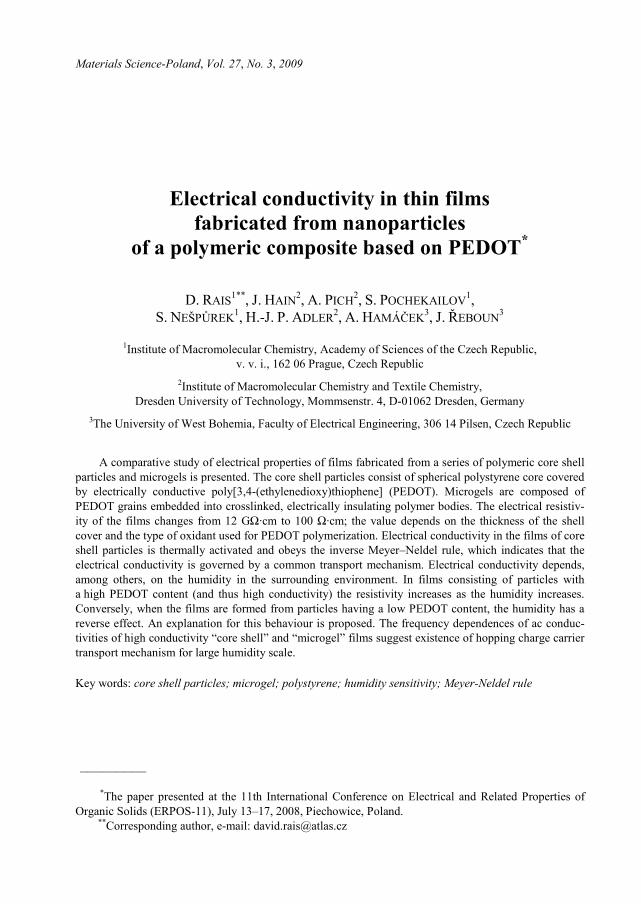
Table 1. Composite particles of the core shell type under study
Run Oxidant for PEDOT
Latex core diameter D [nm]
EDOT: polymera
[g/g]
PEDOT [wt. %]
Resistivity ρ [Ω·cm]
CS1 FeCl3 110c 1:1 0.6 1.0×10¹¹
CS2 FeCl3 520 5:1 2.0 3.1×10⁸
CS3 FeCl3 520 10:1 4.7 7.3×10⁷
CS4 FeCl3 520 1:2 7.3 6.7×10⁷
CS5 FeCl3 520 10:1 35.6 5.3×10⁴
CS6b HAuCl4 520 1:1 26.9 1.0×10²
CS7b HAuCl4 110c 1:1 18.5 3.5×10²
CS8 Na3Mo12PO40 520 1:1 23.0 1.2×10⁵
CS9 (NH4)2S2O8 520 1:1 d 25.7 1.2×10¹⁰
aMass of EDOT related to pure mass of the empty microgel (PVCL/PAAEM). bTemperature of EDOT polymerization was 25 °C. cLatex polymer was (PS/PAAEM)/SDS. dIn this case, the PEDOT concentration is overestimated, because we used the measure-
ments of sulphur element content (by the elemental analysis method) for the calculation of the PEDOT content. The method does not distinguish the sulphur in the PEDOT from the sulphur in the oxidant which remained in the material after washing.
Table 2. Composite materials of the microgel type under study
Run Oxidant for PEDOT
EDOT : polymera
[g/g] PEDOT [wt. %]
Resistivity ρ [Ω·cm]
MG1 FeCl3 1:10 0.5 3.5×10¹⁰
MG2 FeCl3 1:5 0.6 4.4×10⁹
MG3 FeCl3 1:1 4.6 1.7×10⁸
MG4 FeCl3 5:1 5.3 9.5×10⁷
MG5b FeCl3 5:1 30.8 6.1×10²
MG6 HAuCl4 1:1 12.5 3.0x10⁴
aMass of EDOT related to pure mass of the Latex polymer (PS/PAAEM). bReaction medium was 60 mol % ethanol.
Electrical measurements. Thin films of both core shell particles and microgels for electrical measurements were fabricated by drop casting from 1 wt. % aqueous ethanol colloidal dispersion onto glazed ceramic substrates with interdigital gold electrode systems of the coplanar type. The resulting film thicknesses after drying were ca. 1 μm. The distance between the opposite electrodes was 50 μm, the thickness of the gold electrode was 1.1 μm. The electrical current was measured with a Keithley 6517A electrometer, which was also used as a voltage source. The resistances R were determined from the slopes of the current–voltage characteristics. Electrical resistivity ρ and conductivity σ were calculated from the expression ρ = σ –1 RLl/g, where l/g is the electrode geometrical factor (l is the total length of the electrode width and g is the
D. RAIS et al. 772
electrode distance), L is the film thickness. The activation energies of the conductivi-ties were determined from the temperature dependences in the temperature range 20–70 °C. These measurements were performed in a vacuum cryostat with temperature stabilization.
The influence of environmental humidity on ac conductivity was investigated with the sample placed in a chamber with continuous flow of nitrogen (the flow rate was 1000 sccm). The humidity of the flowing gas was changed by mixing wet and dry nitrogen. The flow rates in the branches (dry and wet N2) were adjusted by mass flow regulators, in order to achieve the predetermined RH level. The response kinetics of the equivalent parallel resistance, RP, were measured by repeating cycles of dry nitro-gen flow (400 s) followed by flow of 50 % RH mixed nitrogen (400 s). The cycle was repeated at least 6 times, to evaluate the stability of the sample. ac conductivity pa-rameters were measured with a HIOKI LCR 3532-50 HiTESTER; the testing fre-quency was 12 kHz, except where specified otherwise.
3. Results and discussion
3.1. dc conductivity
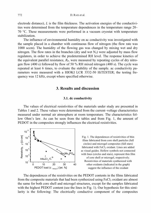
The values of electrical resistivities of the materials under study are presented in Tables 1 and 2. These values were determined from the current–voltage characteristics measured under normal air atmosphere at room temperature. The characteristics fol-low Ohm’s law. As can be seen from the tables and from Fig. 1, the amount of PEDOT in the composites strongly influences the electrical resistivities.
Fig. 1. The dependences of resistivities of thin films fabricated from core shell particles (full circles) and microgel composites (full stars)
fabricated with FeCl3 oxidant. Lines are added as visual guides. Hollow symbols not connected with lines (circles and stars), represent thin film
of core shell or microgel, respectively. Resistivities of materials synthesized with
other oxidants (indicated in the graph) suggest the influence of the oxidant
The dependences of the resistivities on the PEDOT contents in the films fabricated from the composite materials that had been synthesized using FeCl3 oxidant are almost the same for both core shell and microgel structures, except for the samples fabricated with the highest PEDOT content (see the lines in Fig. 1). Our hypothesis for this simi-larity is the following: The electrically conductive component of the composites

Electrical conductivity in thin films fabricated from nanoparticles of a polymeric composite 773
(PEDOT) is polymerized in the form of grains lying either on the surface of the latex core, or in the swollen polymer chains of a microgel (cf. the micrographs (a) and (d) in Fig. 2). If the content of PEDOT does not reach a percolation threshold, the PEDOT grains are separated by insulating polymer chains (mostly the PAAEM part of the template copolymer). From the point of view of charge carrier transport, the situation is similar for both core shell and microgel morphologies. For the materials with higher PEDOT content, the percolation threshold is reached and conductivity increases; the film forming material capacity, which is better in the case of the microgels, might play an important role. The high resistivity of the core shell material CS9, which was oxi-dized with (NH4)2S2O8, does not agree with its apparently very high PEDOT content (cf. Table 1, note d).
Fig. 2. Micrograph examples of the core shell and microgel composites: a) material CS1 with small di-
ameter latex template (110 nm) and low PEDOT content; the rod-shaped grains of PEDOT on the PS/PAAEM particles are separated from each other, b) material CS6 with a large diameter latex template (520 nm) and high PEDOT content; the particles are covered by a compact PEDOT shell surrounded by additional PEDOT grains not attached to the latex particles; oxidant used for PEDOT polymerization is indicated in the photographs. Typical images of the microgel material (MG2 in this case): c) SEM of an array of particles, d) TEM of a single particle. The PEDOT inclusions in microgel can be distinguished
in image (d) as dark, rod-shaped structures surrounding the particle
a)
b)
c)
d)

D. RAIS et al. 774
Figure 1 illustrates the influence of various oxidants used for the PEDOT polym-erization on the properties of the material. The use of Na3Mo12PO40 yielded material (CS8), in which the resistivity and PEDOT content values are not far from the trend exhibited by the FeCl3 oxidized core shell composites (full circles connected by a line in Fig. 1). When HAuCl4 was used, lower resistivities at lower PEDOT content (in comparison with all the other oxidants) were observed in composites of both core shell and microgel morphologies. This is caused, among others, by more intensive creation of “secondary” PEDOT particles – not attached to the latex core, which were observed in CS6 composite (cf. the micrograph in Fig. 2b) and which enhance the electrical contacts among neighbouring latex particles in the thin film. Additionally, the high doping efficiency of the aurate and the presence of Au nanoparticles (AuNPs) formed by the reduction of aurate simultaneously with the EDOT polymerization (AuNPs presence was indicated by SEM, STM analysis, not shown here.) also enhances elec-trical contacts between the particles and, consequently, film resistivity decreases.
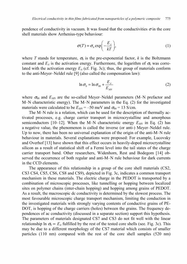
Fig. 3. Arrhenius plots of temperature dependences of conductivities of the series of core shell (a),
and microgel materials (b) as well as relationship between the pre-exponential factor σ0
and the activation energy of the conductivity EA of various core shell materials (c). Meyer–Neldel
parameters estimated from the linear fit (line) in the plot are EMN = –50 meV and σ00 = 13 S/cm
We have studied the temperature dependences of dc conductivity in both core shell and microgel materials. The Arrhenius plots of conductivities the studied materi-als are presented in Fig. 3. All the materials under study are included, except the CS1, in which the high resistivity prevented us from the determination of temperature de-
Electrical conductivity in thin films fabricated from nanoparticles of a polymeric composite 775
pendence of conductivity in vacuum. It was found that the conductivities σ in the core shell materials show Arrhenius-type behaviour:
0( ) exp AETkT
σ σ ⎛ ⎞= −⎜ ⎟⎝ ⎠
, (1)
where T stands for temperature, σ0 is the pre-exponential factor, k is the Boltzmann constant and EA is the activation energy. Furthermore, the logarithm of σ0 was corre-lated with the activation energy EA (cf. Fig. 3c); thus, the group of materials conform to the anti-Meyer–Neldel rule [9] (also called the compensation law):
0 00ln ln A
MN
EE
σ σ= + (2)
where σ00 and EMN are the so-called Meyer–Neldel parameters (M–N prefactor and M–N characteristic energy). The M–N parameters in the Eq. (2) for the investigated materials were calculated to be EMN = –50 meV and σ00 = 13 S/cm.
The M–N rule is a relation, which can be used for the description of thermally ac-tivated processes, e.g. charge carrier transport in microcrystalline and amorphous semiconductors [10–12]. When the M–N characteristic energy EMN in Eq. (2) has a negative value, the phenomenon is called the inverse (or anti-) Meyer–Neldel rule. Up to now, there has been no universal explanation of the origin of the anti-M–N rule behaviour in materials. Several explanations were proposed: For example, Lucovsky and Overhof [13] have shown that this effect occurs in heavily-doped microcrystalline silicon as a result of statistical shift of a Fermi level into the tail states of the charge carrier transport band. Other researchers, Widenhorn, Rest and Bodegom [14] ob-served the occurrence of both regular and anti-M–N rule behaviour for dark currents in the CCD elements.
The appearance of this relationship in a group of the core shell materials (CS2, CS3 CS4, CS5, CS6, CS8 and CS9), depicted in Fig. 3c, indicates a common transport mechanism in these materials. The electric charge in the PEDOT is transported by a combination of microscopic processes, like tunnelling or hopping between localized sites on polymer chains (inter-chain hopping) and hopping among grains of PEDOT. As a result, the macroscopic dc conductivity is determined by the slowest process. The most favourable microscopic charge transport mechanism, limiting the conduction in the investigated materials with strongly varying contents of conductive grains of PE-DOT, is hopping of the charge carriers (holes) between the grains. The frequency de-pendences of ac conductivity (discussed in a separate section) support this hypothesis. The parameters of materials designated CS7 and CS3 do not fit well with the linear relationship ln σ0 ∝ EA fulfilled by the rest of the tested core shells (see. Fig. 3c). This may be due to a different morphology of the CS7 material which consists of smaller particles (110 nm) compared with the rest of the core shell samples (520 nm)
D. RAIS et al. 776
– see Table 1, and in the case of material CS3 due to a large experimental error with the estimation of activation energy EA and pre-exponential factor σ0.
In microgels, the M–N rule-conforming behaviour was not recognized, due to the temperature dependence of the activation energy, which can be seen as non-linear characteristics in Arrhenius plot of some microgels (Fig. 3b). This is possibly a result of microgel insulating polymer template (PVCL/PAAEM) morphology change – the onset of the glass transition at about 30 °C [15].
3.2. Sensitivity of the ac electrical conductance to humidity
Table 3. Humidity sensing properties of selected materials under study
Material
wetPR
at 50.5% RH[Ω]
dryPR
at 3.5% RH [Ω]
Relative sensitivitya S
[%]
dryPR
relative driftb
[%]
Core shell materials CS6 6.28×10² 5.85×10² 7.4 –0.07 CS7 1.19×10³ 1.11×10³ 7.3 0.05 CS5 3.28×10⁵ 3.09×10⁵ 6.1 0.32 CS3 2.4×10⁵ 2.5×10⁸ –100 0.00
Microgel materials MG5 1.19×10⁴ 1.16×10⁴ 2.6 0.42 MG6 8.4×10⁴ 7.14×10⁴ 18 0.02 MG2 5.0×10⁸ 7.5×10⁸ –33 0.06 MG4 4.3×10⁸ 7.2×10⁸ –40 –0.01 MG1 6.2×10⁸ 8.3×10⁸ –25 0.00
aRelative change of RP upon the transition from the dry to wet N2, as defined in Eq. (3).
bChange of dryPR between two consecutive cycles of periodic RH change, as shown
in Fig. 4a.
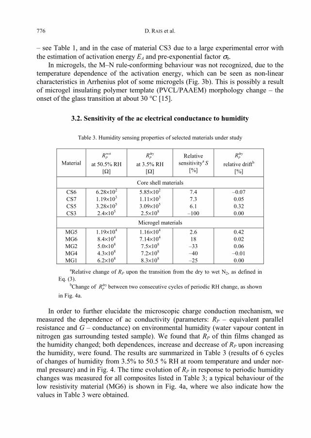
In order to further elucidate the microscopic charge conduction mechanism, we measured the dependence of ac conductivity (parameters: RP – equivalent parallel resistance and G – conductance) on environmental humidity (water vapour content in nitrogen gas surrounding tested sample). We found that RP of thin films changed as the humidity changed; both dependences, increase and decrease of RP upon increasing the humidity, were found. The results are summarized in Table 3 (results of 6 cycles of changes of humidity from 3.5% to 50.5 % RH at room temperature and under nor-mal pressure) and in Fig. 4. The time evolution of RP in response to periodic humidity changes was measured for all composites listed in Table 3; a typical behaviour of the low resistivity material (MG6) is shown in Fig. 4a, where we also indicate how the values in Table 3 were obtained.
Electrical conductivity in thin films fabricated from nanoparticles of a polymeric composite 777
Fig. 4. A typical behaviour of equivalent parallel resistance RP (solid lines) in response to periodic changes of humidity (dotted lines) from 3.5 to 50.5 % RH (a). The dashed lines indicate how the values of
RPwet, RP
dry and the drift of RPdry used for comparison of the materials in Table 3 were obtained from
the periodic humidity change tests and sensitivities to humidity of selected materials (b) under study (stars for various microgels, circles for core shells). The data are combined from Tables 1–3
The relative sensitivity towards the humidity change was calculated from the measured values as follows:
wet dry
dry 100P P
P
R RSR
−= × (3)
where dry wet and P PR R represent the saturated values of ac resistances in dry and wet N2 flow (humidity about 3.5% and 50.5% RH), respectively. In the case of core shell materials (CS5, CS6 and CS7) and microgel materials (MG5 and MG6) RP increased as the RH increased, leading to the positive values of S. In the remaining materials under investigation, reverse behaviour was observed, yielding S < 0. The materials which have higher PEDOT contents and, consequently, smaller ac resistances RP, ex-hibit the former type of response, while the samples with low PEDOT content and high RP behave in the opposite manner. Thus, these materials can be assigned, depend-ing on their PEDOT content, to one of two classes; corresponding to the two comple-mentary types of humidity response, as can be seen in Fig 4b.
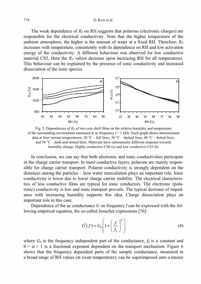
To explain the differences in the behaviour of humidity response, we concentrated on a more detailed study of two core shell materials CS6 and CS3 (highly and low conductive, respectively). RP of the layers fabricated from these materials in function of relative humidity are given in Fig. 5. The equivalent parallel resistance, RP, of the conductive layer of CS6 increases as the relative humidity increases at all tested tem-peratures (20, 30, 40 and 50 °C). This characteristic cannot be explained by the model of purely ionic conductivity but it can be assumed that intercalation of water mole-cules among the core shell particles takes place. Greater interparticle distances lead to a decrease in the probability of charge carrier transport and, consequently, to an elec-tric current decrease, i.e., increase of impedance and resistance.
D. RAIS et al. 778
The weak dependence of RP on RH suggests that polarons (electronic charges) are responsible for the electrical conductivity. Note that the higher temperature of the ambient atmosphere, the higher is the amount of water at a fixed RH. Therefore, RP increases with temperature, consistently with its dependence on RH and low activation energy of the conductivity. A different behaviour was observed for low conductive material CS3. Here the RP values decrease upon increasing RH for all temperatures. This behaviour can be explained by the presence of ionic conductivity and increased dissociation of the ionic species.
Fig. 5. Dependences of RP of two core shell films on the relative humidity and temperature
of the surrounding environment measured at ac frequency f = 1 kHz. Each graph shows measurement data at four various temperatures: 20 °C – full lines, 30 °C – dashed lines, 40 °C – dotted lines,
and 50 °C – dash-and-dotted lines. Materials have substantially different response towards humidity change. Highly conductive CS6 (a) and low conductive CS3 (b)
In conclusion, we can say that both electronic and ionic conductivities participate in the charge carrier transport. In more conductive layers, polarons are mainly respon-sible for charge carrier transport. Polaron conductivity is strongly dependent on the distances among the particles – here water intercalation plays an important role. Ionic conductivity is lower due to lower charge carrier mobility. The electrical characteris-tics of less conductive films are typical for ionic conductors. The electronic (pola-ronic) conductivity is low and ionic transport prevails. The typical decrease of imped-ance with increasing humidity supports this idea. Charge dissociation plays an important role in this case.
Dependence of the ac conductance G on frequency f can be expressed with the fol-lowing empirical equation, the so-called Jonscher expressions [16]:
00
( ) 1 fG f Gf
α⎛ ⎞⎛ ⎞⎜ ⎟′ = + ⎜ ⎟⎜ ⎟⎝ ⎠⎝ ⎠
(4)
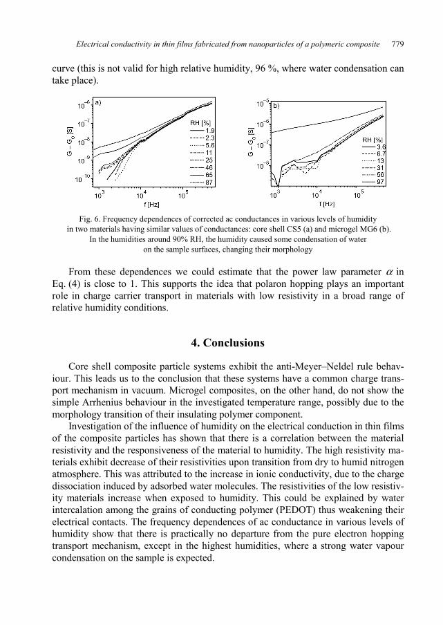
where G0 is the frequency independent part of the conductance, f0 is a constant and 0 > α > 1 is a fractional exponent dependent on the transport mechanism. Figure 6 shows that the frequency dependent parts of the sample conductance, measured in a broad range of RH values (at room temperature), can be superimposed onto a master
Electrical conductivity in thin films fabricated from nanoparticles of a polymeric composite 779
curve (this is not valid for high relative humidity, 96 %, where water condensation can take place).
Fig. 6. Frequency dependences of corrected ac conductances in various levels of humidity in two materials having similar values of conductances: core shell CS5 (a) and microgel MG6 (b).
In the humidities around 90% RH, the humidity caused some condensation of water on the sample surfaces, changing their morphology
From these dependences we could estimate that the power law parameter α in Eq. (4) is close to 1. This supports the idea that polaron hopping plays an important role in charge carrier transport in materials with low resistivity in a broad range of relative humidity conditions.
4. Conclusions
Core shell composite particle systems exhibit the anti-Meyer–Neldel rule behav-iour. This leads us to the conclusion that these systems have a common charge trans-port mechanism in vacuum. Microgel composites, on the other hand, do not show the simple Arrhenius behaviour in the investigated temperature range, possibly due to the morphology transition of their insulating polymer component.
Investigation of the influence of humidity on the electrical conduction in thin films of the composite particles has shown that there is a correlation between the material resistivity and the responsiveness of the material to humidity. The high resistivity ma-terials exhibit decrease of their resistivities upon transition from dry to humid nitrogen atmosphere. This was attributed to the increase in ionic conductivity, due to the charge dissociation induced by adsorbed water molecules. The resistivities of the low resistiv-ity materials increase when exposed to humidity. This could be explained by water intercalation among the grains of conducting polymer (PEDOT) thus weakening their electrical contacts. The frequency dependences of ac conductance in various levels of humidity show that there is practically no departure from the pure electron hopping transport mechanism, except in the highest humidities, where a strong water vapour condensation on the sample is expected.
D. RAIS et al. 780
Acknowledgements
This work was supported by the Ministry of Education, Youth and Sports of the Czech Republic (grant No. 1041/2006-32, COST) and by the Deutsche Forschungsgemeinschaft (DFG, research project SFB 287 Reactive Polymers).
References
[1] SHIRAKAWA H., Angew. Chem., 113 (2001), 2642. [2] MACDIARMID A.G., Angew. Chem., 113 (2001), 2649. [3] HEEGER A.J., Angew. Chem., 113 (2001), 2660. [4] WEI Z., XU J., HOU J., ZHOU W., PU S., J. Mater. Sci., 41 (2006), 3923. [5] OUYANG J., CHU C.-W., CHEN F.-C., XU Q., YANG Y., Adv. Funct. Mater., 15 (2005), 203. [6] ERDEN A., SAHIN E., GÜLLÜ M., TOPPARE L., Eur. Polym. J., 42 (2006), 1866. [7] HENDERSON J.A.M., SAUNDERS J.M., MRKIC J., KENT P., GORE J., SAUNDERS B.R., J. Mater. Chem.,
11 (2001), 3037. [8] HAIN J., PICH A., ADLER H.-J., RAIS D., NEŠPŮREK S., Macromol. Symp., 288 (2008), 61. [9] MEYER W., NELDEL H., Z. Tech. Phys., 18 (1937), 588.
[10] RAM S.K., KUMAR S., ROCA I CABARROCAS P., J. Non-Cryst. Solids, 354 (2008), 2263. [11] ABTEW T.A., ZHANG M., PAN Y., DRABOLD D.A., J. Non-Cryst. Solids, 354 (2008), 2909. [12] MEIJER E.J., MATTERS M., HERWIG P.T., DE LEEUW D.M., KLAPWIJK T.M., Appl. Phys. Lett.,
76 (2000), 3433. [13] LUCOVSKY G., OVERHOF H., J. Non-Cryst. Solids, 164–166 (1993), 973. [14] WIDENHORN R., REST A., BODEGOM E., J. Appl. Phys., 91 (2002), 6524. [15] BOYKO V., LU Y., RICHTER S., ARNDT K.-F., PICH A., ADLER H.-J., Polymer, 44 (2003), 7821. [16] JONSCHER A.K., Dielectric Relaxation in Solids, Chelsea Dielectric Press, London, 1983.
Received 25 September 2008 Revised 3 March 2009


![13. Osdi Ashari Optical and Structural Properties of ZnO Thin Films Fabricated by Sol-Gel Method Ok[1]](https://static.fdocuments.in/doc/165x107/56d6bd5c1a28ab30168dae69/13-osdi-ashari-optical-and-structural-properties-of-zno-thin-films-fabricated.jpg)