Electrical Components for the Railway Industry -...
96
Unrestricted / © Siemens AG 2014. All Rights Reserved. www.siemens.com/railway-components Electrical Components for the Railway Industry SIRIUS – 3RT2 motor contactors up to 37 kW
Transcript of Electrical Components for the Railway Industry -...
Unrestricted / © Siemens AG 2014. All Rights Reserved. www.siemens.com/railway-components
Electrical Components for the
Railway Industry
SIRIUS – 3RT2 motor contactors up to 37 kW

Unrestricted / © Siemens AG 2014. All Rights Reserved.
2014-10-27 Page 2 Michael Staber, Railway Presentation V 7.3
► Important links
► Contactors S2
► Contactors S0
► Drawings
► Versions
► Technical Data
► Description
► Introduction
► Contactors S00
SIRIUS – 3RT2 motor contactors up to 7.5 kW
Introduction
Contactors S00
Unrestricted / © Siemens AG 2014. All Rights Reserved.
2014-10-27 Page 3 Michael Staber, Railway Presentation V 7.3
► Important links
► Contactors S2
► Contactors S0
► Drawings
► Versions
► Technical Data
► Description
► Introduction
► Contactors S00
SIRIUS – 3RT2 motor contactors up to 7.5 kW
Description
Contactors S00
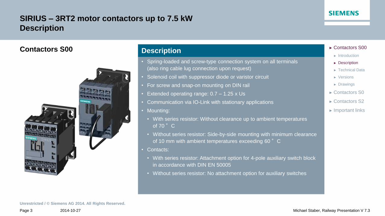
• Spring-loaded and screw-type connection system on all terminals
(also ring cable lug connection upon request)
• Solenoid coil with suppressor diode or varistor circuit
• For screw and snap-on mounting on DIN rail
• Extended operating range: 0.7 – 1.25 x Us
• Communication via IO-Link with stationary applications
• Mounting:
• With series resistor: Without clearance up to ambient temperatures
of 70 °C
• Without series resistor: Side-by-side mounting with minimum clearance
of 10 mm with ambient temperatures exceeding 60 °C
• Contacts:
• With series resistor: Attachment option for 4-pole auxiliary switch block
in accordance with DIN EN 50005
• Without series resistor: No attachment option for auxiliary switches
Description

Unrestricted / © Siemens AG 2014. All Rights Reserved.
2014-10-27 Page 4 Michael Staber, Railway Presentation V 7.3
► Important links
► Contactors S2
► Contactors S0
► Drawings
► Versions
► Technical Data
► Description
► Introduction
► Contactors S00
SIRIUS – 3RT2 motor contactors up to 7.5 kW
Technical Data
Contactors S00
Without resistor With resistor
Article-No. 3RT2015 3RT2016 3RT2017 3RT2018
Power kW / 400V 3 4 5.5 7.5
Currents
[A]
DC-1 / 24V
DC-1 / 110V
15
1.5
20
2.1
DC-3;5 / 24V
DC-3;5 / 110V
15
0,1
20
0.1
Coil power
[W]
Closing
Holding
2.8
2.8
12
4
Weight [ kg / PE ] 0.28 0.30

Unrestricted / © Siemens AG 2014. All Rights Reserved.
2014-10-27 Page 5 Michael Staber, Railway Presentation V 7.3
► Important links
► Contactors S2
► Contactors S0
► Drawings
► 7.5 kW
► 5.5 kW
► 4 kW
► 3 kW
► Versions
► Technical Data
► Description
► Introduction
► Contactors S00
SIRIUS – 3RT2 motor contactors up to 7.5 kW
Versions
Size S00
Power = 3 kW without circuit
Article-No. Connection diagram Screw-type Spring-loaded Voltage Us
3RT2015 - 1 1HB41 2HB41 24V DC
1 1HB42 2HB42 24V DC
NO NC
Without series resistor Operating range: 0.7 … 1.25 x Us
No attachment option for auxiliary switches
A clearance of 10 mm is required for side-by-side mounting at ambient temperatures
>60°C

Unrestricted / © Siemens AG 2014. All Rights Reserved.
2014-10-27 Page 6 Michael Staber, Railway Presentation V 7.3
► Important links
► Contactors S2
► Contactors S0
► Drawings
► 7.5 kW
► 5.5 kW
► 4 kW
► 3 kW
► Versions
► Technical Data
► Description
► Introduction
► Contactors S00
SIRIUS – 3RT2 motor contactors up to 7.5 kW
Versions
Size S00
Power = 3 kW with diode
Article-No. Connection diagram Screw-type Spring-loaded Voltage Us
3RT2015 - 1 1JB41 2JB41 24V DC
1 1JB42 2JB42 24V DC
NO NC
Without series resistor Operating range: 0.7 … 1.25 x Us
No attachment option for auxiliary switches
A clearance of 10 mm is required for side-by-side mounting at ambient temperatures
>60°C

Unrestricted / © Siemens AG 2014. All Rights Reserved.
2014-10-27 Page 7 Michael Staber, Railway Presentation V 7.3
► Important links
► Contactors S2
► Contactors S0
► Drawings
► 7.5 kW
► 5.5 kW
► 4 kW
► 3 kW
► Versions
► Technical Data
► Description
► Introduction
► Contactors S00
SIRIUS – 3RT2 motor contactors up to 7.5 kW
Versions
Size S00
Power = 3 kW with suppressor diode
Article-No. Connection diagram Screw-type Spring-loaded Voltage Us
3RT2015 - 1 1KB41 2KB41 24V DC
1 2KA42 12V DC
1 1KB42 2KB42 24V DC
NO NC
Without series resistor Operating range: 0.7 … 1.25 x Us
No attachment option for auxiliary switches
A clearance of 10 mm is required for side-by-side mounting at ambient temperatures
>60°C

Unrestricted / © Siemens AG 2014. All Rights Reserved.
2014-10-27 Page 8 Michael Staber, Railway Presentation V 7.3
► Important links
► Contactors S2
► Contactors S0
► Drawings
► 7.5 kW
► 5.5 kW
► 4 kW
► 3 kW
► Versions
► Technical Data
► Description
► Introduction
► Contactors S00
SIRIUS – 3RT2 motor contactors up to 7.5 kW
Versions
Size S00
Power = 3 kW with varistor
NO NC Article-No. Connection diagram Screw-type Spring-loaded Voltage Us
3RT2015 - 1 1QB41 2QB41 24V DC
1 1QB42 2QB42 24V DC
NO NC
Without series resistor Operating range: 0.7 … 1.25 x Us
No attachment option for auxiliary switches
A clearance of 10 mm is required for side-by-side mounting at ambient temperatures
>60°C

Unrestricted / © Siemens AG 2014. All Rights Reserved.
2014-10-27 Page 9 Michael Staber, Railway Presentation V 7.3
► Important links
► Contactors S2
► Contactors S0
► Drawings
► 7.5 kW
► 5.5 kW
► 4 kW
► 3 kW
► Versions
► Technical Data
► Description
► Introduction
► Contactors S00
SIRIUS – 3RT2 motor contactors up to 7.5 kW
Versions
Size S00
Power = 4 kW without circuit
Article-No. Connection diagram Screw-type Spring-loaded Voltage Us
3RT2016 - 1 1HB41 2HB41 24V DC
1 1HB42 2HB42 24V DC
NO NC
Without series resistor Operating range: 0.7 … 1.25 x Us
No attachment option for auxiliary switches
A clearance of 10 mm is required for side-by-side mounting at ambient temperatures
>60°C

Unrestricted / © Siemens AG 2014. All Rights Reserved.
2014-10-27 Page 10 Michael Staber, Railway Presentation V 7.3
► Important links
► Contactors S2
► Contactors S0
► Drawings
► 7.5 kW
► 5.5 kW
► 4 kW
► 3 kW
► Versions
► Technical Data
► Description
► Introduction
► Contactors S00
SIRIUS – 3RT2 motor contactors up to 7.5 kW
Versions
Size S00
Power = 4 kW with diode
Article-No. Connection diagram Screw-type Spring-loaded Voltage Us
3RT2016 - 1 1JB41 2JB41 24V DC
1 1JB42 2JB42 24V DC
NO NC
Without series resistor Operating range: 0.7 … 1.25 x Us
No attachment option for auxiliary switches
A clearance of 10 mm is required for side-by-side mounting at ambient temperatures
>60°C

Unrestricted / © Siemens AG 2014. All Rights Reserved.
2014-10-27 Page 11 Michael Staber, Railway Presentation V 7.3
► Important links
► Contactors S2
► Contactors S0
► Drawings
► 7.5 kW
► 5.5 kW
► 4 kW
► 3 kW
► Versions
► Technical Data
► Description
► Introduction
► Contactors S00
SIRIUS – 3RT2 motor contactors up to 7.5 kW
Versions
Size S00
Power = 4 kW with diode
Without series resistor Operating range: 0.7 … 1.25 x Us
No attachment option for auxiliary switches
A clearance of 10 mm is required for side-by-side mounting at ambient temperatures
>60°C
Article-No. Connection diagram Spring-loaded Control voltage Us
3RT2016 - 1 2FB41 – 1AA0 24V DC
NO NC
Unrestricted / © Siemens AG 2014. All Rights Reserved.
2014-10-27 Page 12 Michael Staber, Railway Presentation V 7.3
► Important links
► Contactors S2
► Contactors S0
► Drawings
► 7.5 kW
► 5.5 kW
► 4 kW
► 3 kW
► Versions
► Technical Data
► Description
► Introduction
► Contactors S00
SIRIUS – 3RT2 motor contactors up to 7.5 kW
Versions
Size S00
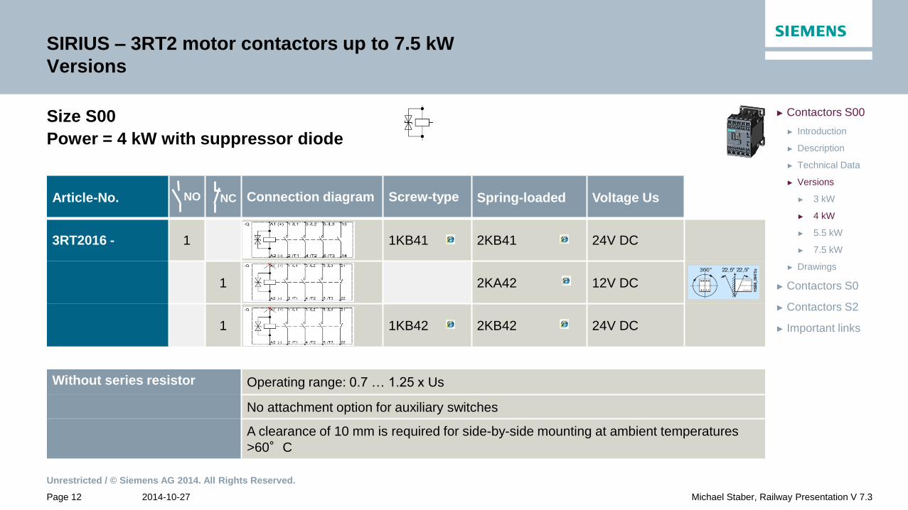
Power = 4 kW with suppressor diode
Article-No. Connection diagram Screw-type Spring-loaded Voltage Us
3RT2016 - 1 1KB41 2KB41 24V DC
1 2KA42 12V DC
1 1KB42 2KB42 24V DC
NO NC
Without series resistor Operating range: 0.7 … 1.25 x Us
No attachment option for auxiliary switches
A clearance of 10 mm is required for side-by-side mounting at ambient temperatures
>60°C

Unrestricted / © Siemens AG 2014. All Rights Reserved.
2014-10-27 Page 13 Michael Staber, Railway Presentation V 7.3
► Important links
► Contactors S2
► Contactors S0
► Drawings
► 7.5 kW
► 5.5 kW
► 4 kW
► 3 kW
► Versions
► Technical Data
► Description
► Introduction
► Contactors S00
SIRIUS – 3RT2 motor contactors up to 7.5 kW
Versions
Size S00
Power = 4 kW with varistor
Without series resistor Operating range: 0.7 … 1.25 x Us
No attachment option for auxiliary switches
A clearance of 10 mm is required for side-by-side mounting at ambient temperatures
>60°C
Article-No. Connection diagram Screw-type Spring-loaded Voltage Us
3RT2016 - 1 1QB41 2QB41 24V DC
1 1QB42 2QB42 24V DC
NO NC

Unrestricted / © Siemens AG 2014. All Rights Reserved.
2014-10-27 Page 14 Michael Staber, Railway Presentation V 7.3
► Important links
► Contactors S2
► Contactors S0
► Drawings
► 7.5 kW
► 5.5 kW
► 4 kW
► 3 kW
► Versions
► Technical Data
► Description
► Introduction
► Contactors S00
SIRIUS – 3RT2 motor contactors up to 7.5 kW
Versions
Size S00
Power = 4 kW with varistor and series resistor
With series resistor Operating range: 0.7 … 1.25 x Us
Expansion of auxiliary switches analogous to standard contactors
Mounting without clearance up to ambient temperatures of 70°C
1 NC contact is wired to the series resistor
Article-No. Connection diagram Spring-loaded Control voltage Us
3RT2016 - 1 2LJ82 – 0LA0 72V DC
NO NC
Unrestricted / © Siemens AG 2014. All Rights Reserved.
2014-10-27 Page 15 Michael Staber, Railway Presentation V 7.3
► Important links
► Contactors S2
► Contactors S0
► Drawings
► 7.5 kW
► 5.5 kW
► 4 kW
► 3 kW
► Versions
► Technical Data
► Description
► Introduction
► Contactors S00
SIRIUS – 3RT2 motor contactors up to 7.5 kW
Versions
Size S00
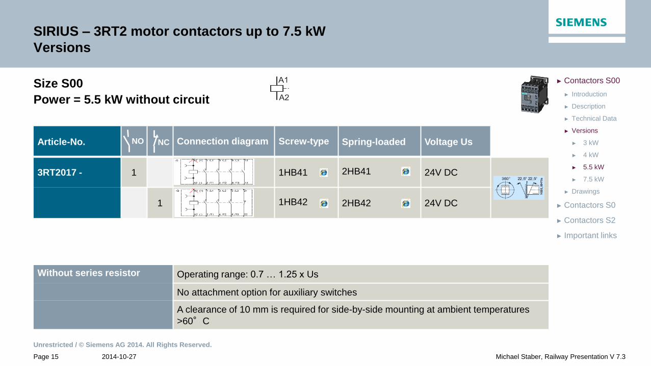
Power = 5.5 kW without circuit
Article-No. Connection diagram Screw-type Spring-loaded Voltage Us
3RT2017 - 1 1HB41 2HB41 24V DC
1 1HB42 2HB42 24V DC
NO NC
Without series resistor Operating range: 0.7 … 1.25 x Us
No attachment option for auxiliary switches
A clearance of 10 mm is required for side-by-side mounting at ambient temperatures
>60°C

Unrestricted / © Siemens AG 2014. All Rights Reserved.
2014-10-27 Page 16 Michael Staber, Railway Presentation V 7.3
► Important links
► Contactors S2
► Contactors S0
► Drawings
► 7.5 kW
► 5.5 kW
► 4 kW
► 3 kW
► Versions
► Technical Data
► Description
► Introduction
► Contactors S00
SIRIUS – 3RT2 motor contactors up to 7.5 kW
Versions
Size S00
Power = 5.5 kW with diode
Article-No. Connection diagram Screw-type Spring-loaded Voltage Us
3RT2017 - 1 1JB41 2JB41 24V DC
1 1JB42 2JB42 24V DC
NO NC
Without series resistor Operating range: 0.7 … 1.25 x Us
No attachment option for auxiliary switches
A clearance of 10 mm is required for side-by-side mounting at ambient temperatures
>60°C

Unrestricted / © Siemens AG 2014. All Rights Reserved.
2014-10-27 Page 17 Michael Staber, Railway Presentation V 7.3
► Important links
► Contactors S2
► Contactors S0
► Drawings
► 7.5 kW
► 5.5 kW
► 4 kW
► 3 kW
► Versions
► Technical Data
► Description
► Introduction
► Contactors S00
SIRIUS – 3RT2 motor contactors up to 7.5 kW
Versions
Size S00
Power = 5.5 kW with diode
Without series resistor Operating range: 0.7 … 1.25 x Us
No attachment option for auxiliary switches
A clearance of 10 mm is required for side-by-side mounting at ambient temperatures
>60°C
Article-No. Connection diagram Screw-type Control voltage Us
3RT2017 - 1 1FB41 – 1AA0 24V DC
NO NC

Unrestricted / © Siemens AG 2014. All Rights Reserved.
2014-10-27 Page 18 Michael Staber, Railway Presentation V 7.3
► Important links
► Contactors S2
► Contactors S0
► Drawings
► 7.5 kW
► 5.5 kW
► 4 kW
► 3 kW
► Versions
► Technical Data
► Description
► Introduction
► Contactors S00
SIRIUS – 3RT2 motor contactors up to 7.5 kW
Versions
Size S00
Power = 5.5 kW with suppressor diode
Article-No. Connection diagram Screw-type Spring-loaded Voltage Us
3RT2017 - 1 2KA42 12V DC
1 1KB41 2KB41 24V DV
1 1KB42 2KB42 24V DC
1 2KF41 110V DC
1 2KF42 110V DC
1 2KG41 125V DC
1 2KG42 125V DC
NO NC
Without series resistor Operating range: 0.7 … 1.25 x Us
No attachment option for auxiliary switches
A clearance of 10 mm is required for side-by-side mounting at ambient temperatures
>60°C

Unrestricted / © Siemens AG 2014. All Rights Reserved.
2014-10-27 Page 19 Michael Staber, Railway Presentation V 7.3
► Important links
► Contactors S2
► Contactors S0
► Drawings
► 7.5 kW
► 5.5 kW
► 4 kW
► 3 kW
► Versions
► Technical Data
► Description
► Introduction
► Contactors S00
SIRIUS – 3RT2 motor contactors up to 7.5 kW
Versions
Size S00
Power = 5.5 kW with suppressor diode
Article-No. Connection diagram Ring-terminals Control voltage Us
3RT2017 - 1 4KB41 24V DC
1 4KB42 24V DC
NO NC
Without series resistor Operating range: 0.7 … 1.25 x Us
No attachment option for auxiliary switches
A clearance of 10 mm is required for side-by-side mounting at ambient temperatures
>60°C

Unrestricted / © Siemens AG 2014. All Rights Reserved.
2014-10-27 Page 20 Michael Staber, Railway Presentation V 7.3
► Important links
► Contactors S2
► Contactors S0
► Drawings
► 7.5 kW
► 5.5 kW
► 4 kW
► 3 kW
► Versions
► Technical Data
► Description
► Introduction
► Contactors S00
SIRIUS – 3RT2 motor contactors up to 7.5 kW
Versions
Size S00
Power = 5.5 kW with varistor
Article-No. Connection diagram Spring-loaded Control voltage Us
3RT2017 - 1 2LB41 24V DC
1 2LB42 24V DC
1 2LF41 110V DC
1 2LF42 110V DC
NO NC
Without series resistor Operating range: 0.7 … 1.25 x Us
No attachment option for auxiliary switches
A clearance of 10 mm is required for side-by-side mounting at ambient temperatures
>60°C
Unrestricted / © Siemens AG 2014. All Rights Reserved.
2014-10-27 Page 21 Michael Staber, Railway Presentation V 7.3
► Important links
► Contactors S2
► Contactors S0
► Drawings
► 7.5 kW
► 5.5 kW
► 4 kW
► 3 kW
► Versions
► Technical Data
► Description
► Introduction
► Contactors S00
SIRIUS – 3RT2 motor contactors up to 7.5 kW
Versions
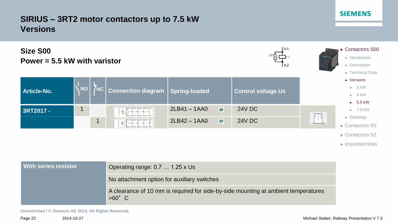
Size S00
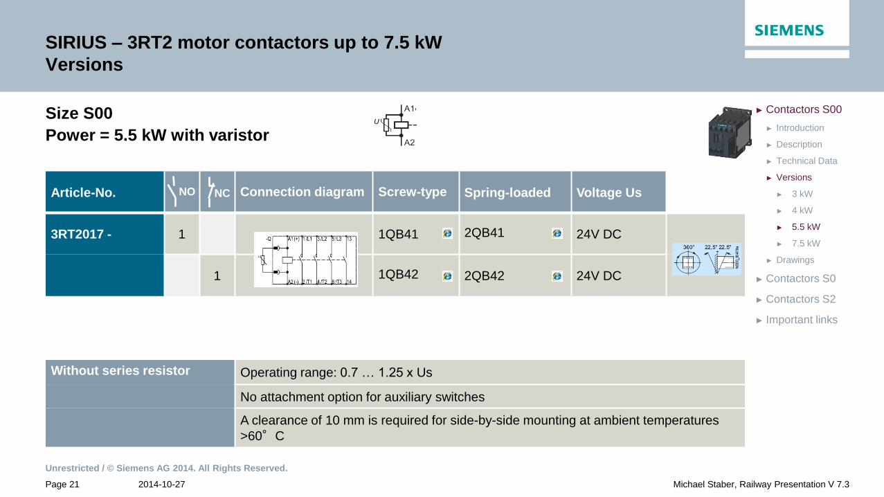
Power = 5.5 kW with varistor
Article-No. Connection diagram Screw-type Spring-loaded Voltage Us
3RT2017 - 1 1QB41 2QB41 24V DC
1 1QB42 2QB42 24V DC
NO NC
Without series resistor Operating range: 0.7 … 1.25 x Us
No attachment option for auxiliary switches
A clearance of 10 mm is required for side-by-side mounting at ambient temperatures
>60°C
Unrestricted / © Siemens AG 2014. All Rights Reserved.
2014-10-27 Page 22 Michael Staber, Railway Presentation V 7.3
► Important links
► Contactors S2
► Contactors S0
► Drawings
► 7.5 kW
► 5.5 kW
► 4 kW
► 3 kW
► Versions
► Technical Data
► Description
► Introduction
► Contactors S00
SIRIUS – 3RT2 motor contactors up to 7.5 kW
Versions
Size S00
Power = 5.5 kW with varistor
Article-No. Connection diagram Spring-loaded Control voltage Us
3RT2017 - 1 2LB41 – 1AA0 24V DC
1 2LB42 – 1AA0 24V DC
With series resistor
Operating range: 0.7 … 1.25 x Us
No attachment option for auxiliary switches
A clearance of 10 mm is required for side-by-side mounting at ambient temperatures
>60°C
NO NC

Unrestricted / © Siemens AG 2014. All Rights Reserved.
2014-10-27 Page 23 Michael Staber, Railway Presentation V 7.3
► Important links
► Contactors S2
► Contactors S0
► Drawings
► 7.5 kW
► 5.5 kW
► 4 kW
► 3 kW
► Versions
► Technical Data
► Description
► Introduction
► Contactors S00
SIRIUS – 3RT2 motor contactors up to 7.5 kW
Versions
Size S00
Power = 5.5 kW with varistor
Article-No. Connection diagram Ring-terminals Control voltage Us
3RT2017 - 1 4LB41 24V DC
1 4LB42 24V DC
NO NC
Without series resistor Operating range: 0.7 … 1.25 x Us
No attachment option for auxiliary switches
A clearance of 10 mm is required for side-by-side mounting at ambient temperatures
>60°C

Unrestricted / © Siemens AG 2014. All Rights Reserved.
2014-10-27 Page 24 Michael Staber, Railway Presentation V 7.3
► Important links
► Contactors S2
► Contactors S0
► Drawings
► 7.5 kW
► 5.5 kW
► 4 kW
► 3 kW
► Versions
► Technical Data
► Description
► Introduction
► Contactors S00
SIRIUS – 3RT2 motor contactors up to 7.5 kW
Versions
Size S00
Power = 5.5 kW with suppressordiode and series resistor
Article-No. Connection diagram Spring-loaded Control voltage Us
3RT2017 - 1 2KF41 – 1AA0 110V DC
NO NC
Circuit diagram
With series resistor Operating range: 0.7 … 1.25 x Us
Expansion of auxiliary switches analogous to standard contactors
Mounting without clearance up to ambient temperatures of 70°C

Unrestricted / © Siemens AG 2014. All Rights Reserved.
2014-10-27 Page 25 Michael Staber, Railway Presentation V 7.3
► Important links
► Contactors S2
► Contactors S0
► Drawings
► 7.5 kW
► 5.5 kW
► 4 kW
► 3 kW
► Versions
► Technical Data
► Description
► Introduction
► Contactors S00
SIRIUS – 3RT2 motor contactors up to 7.5 kW
Versions
Size S00
Power = 5.5 kW with suppressordiode and series resistor
Article-No. Connection diagram Spring-loaded Control voltage Us
3RT2017 - 1 2KB42 - 0LA0 24V DC
1 2KF42 - 0LA0 110V DC
1 2KG42 - 0LA0 125V DC
Circuit diagram
With series resistor Operating range: 0.7 … 1.25 x Us
Expansion of auxiliary switches analogous to standard contactors
Mounting without clearance up to ambient temperatures of 70°C
1 NC contact is wired to the series resistor
NO NC

Unrestricted / © Siemens AG 2014. All Rights Reserved.
2014-10-27 Page 26 Michael Staber, Railway Presentation V 7.3
► Important links
► Contactors S2
► Contactors S0
► Drawings
► 7.5 kW
► 5.5 kW
► 4 kW
► 3 kW
► Versions
► Technical Data
► Description
► Introduction
► Contactors S00
SIRIUS – 3RT2 motor contactors up to 7.5 kW
Versions
Size S00
Power = 5.5 kW with suppressordiode and series resistor
Article-No. Connection diagram Spring-loaded Control voltage Us
3RT2017 - 1 2KB42 - 1LA0 24V DC
1 2KF42 - 1LA0 110V DC
NO NC
Circuit diagram
With series resistor Operating range: 0.7 … 1.25 x Us
Expansion of auxiliary switches analogous to standard contactors
Mounting without clearance up to ambient temperatures of 70°C
1 NC contact is wired to the series resistor

Unrestricted / © Siemens AG 2014. All Rights Reserved.
2014-10-27 Page 27 Michael Staber, Railway Presentation V 7.3
► Important links
► Contactors S2
► Contactors S0
► Drawings
► 7.5 kW
► 5.5 kW
► 4 kW
► 3 kW
► Versions
► Technical Data
► Description
► Introduction
► Contactors S00
SIRIUS – 3RT2 motor contactors up to 7.5 kW
Versions
Size S00
Power = 5.5 kW with varistor and series resistor
Article-No. Connection diagram Ring-terminals Control voltage Us
3RT2017 - 1 4KB42 - 0LA0 24V DC
NO NC
Circuit diagram
With series resistor Operating range: 0.7 … 1.25 x Us
Expansion of auxiliary switches analogous to standard contactors
Mounting without clearance up to ambient temperatures of 70°C
1 NC contact is wired to the series resistor
Unrestricted / © Siemens AG 2014. All Rights Reserved.
2014-10-27 Page 28 Michael Staber, Railway Presentation V 7.3
► Important links
► Contactors S2
► Contactors S0
► Drawings
► 7.5 kW
► 5.5 kW
► 4 kW
► 3 kW
► Versions
► Technical Data
► Description
► Introduction
► Contactors S00
SIRIUS – 3RT2 motor contactors up to 7.5 kW
Versions
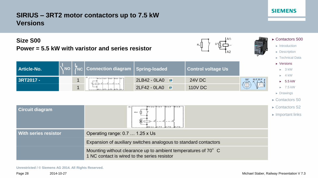
Size S00
Power = 5.5 kW with varistor and series resistor
Article-No. Connection diagram Spring-loaded Control voltage Us
3RT2017 - 1 2LB42 - 0LA0 24V DC
1 2LF42 - 0LA0 110V DC
NO NC
Circuit diagram
With series resistor Operating range: 0.7 … 1.25 x Us
Expansion of auxiliary switches analogous to standard contactors
Mounting without clearance up to ambient temperatures of 70°C
1 NC contact is wired to the series resistor
Unrestricted / © Siemens AG 2014. All Rights Reserved.
2014-10-27 Page 29 Michael Staber, Railway Presentation V 7.3
► Important links
► Contactors S2
► Contactors S0
► Drawings
► 7.5 kW
► 5.5 kW
► 4 kW
► 3 kW
► Versions
► Technical Data
► Description
► Introduction
► Contactors S00
SIRIUS – 3RT2 motor contactors up to 7.5 kW
Versions
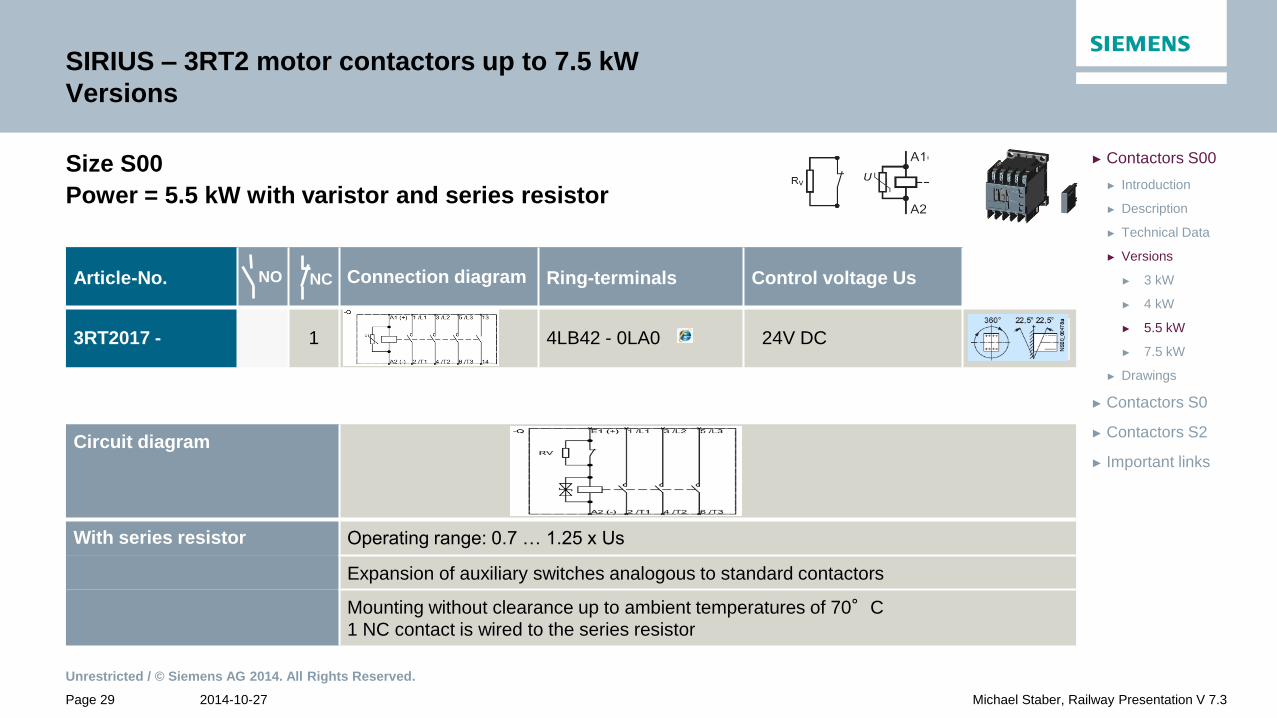
Size S00
Power = 5.5 kW with varistor and series resistor
Article-No. Connection diagram Ring-terminals Control voltage Us
3RT2017 - 1 4LB42 - 0LA0 24V DC
NO NC
Circuit diagram
With series resistor Operating range: 0.7 … 1.25 x Us
Expansion of auxiliary switches analogous to standard contactors
Mounting without clearance up to ambient temperatures of 70°C
1 NC contact is wired to the series resistor

Unrestricted / © Siemens AG 2014. All Rights Reserved.
2014-10-27 Page 30 Michael Staber, Railway Presentation V 7.3
► Important links
► Contactors S2
► Contactors S0
► Drawings
► 7.5 kW
► 5.5 kW
► 4 kW
► 3 kW
► Versions
► Technical Data
► Description
► Introduction
► Contactors S00
SIRIUS – 3RT2 motor contactors up to 7.5 kW
Versions
Size S00
Power = 5.5 kW with varistor and series resistor
Circuit diagram
With series resistor
Operating range: 0.7 … 1.25 x Us
Expansion of auxiliary switches analogous to standard contactors
Mounting without clearance up to ambient temperatures of 70°C
1 NC contact is wired to the series resistor
Article-No. Connection diagram Spring-loaded Control voltage Us
3RT2017 - 1 2LB42 - 1LA0 24V DC
1 2LF42 - 1LA0 110V DC
NO NC

Unrestricted / © Siemens AG 2014. All Rights Reserved.
2014-10-27 Page 31 Michael Staber, Railway Presentation V 7.3
► Important links
► Contactors S2
► Contactors S0
► Drawings
► 7.5 kW
► 5.5 kW
► 4 kW
► 3 kW
► Versions
► Technical Data
► Description
► Introduction
► Contactors S00
SIRIUS – 3RT2 motor contactors up to 7.5 kW
Versions
Size S00
Power = 5.5 kW with varistor and series resistor
Article-No. Connection diagram Spring-loaded Control voltage Us
3RT2017 - 1 2LJ82 – 0LA0 72V DC
NO NC
Circuit diagram
With series resistor Operating range: 0.7 … 1.25 x Us
Expansion of auxiliary switches analogous to standard contactors
Mounting without clearance up to ambient temperatures of 70°C
1 NC contact is wired to the series resistor
Unrestricted / © Siemens AG 2014. All Rights Reserved.
2014-10-27 Page 32 Michael Staber, Railway Presentation V 7.3
► Important links
► Contactors S2
► Contactors S0
► Drawings
► 7.5 kW
► 5.5 kW
► 4 kW
► 3 kW
► Versions
► Technical Data
► Description
► Introduction
► Contactors S00
SIRIUS – 3RT2 motor contactors up to 7.5 kW
Versions
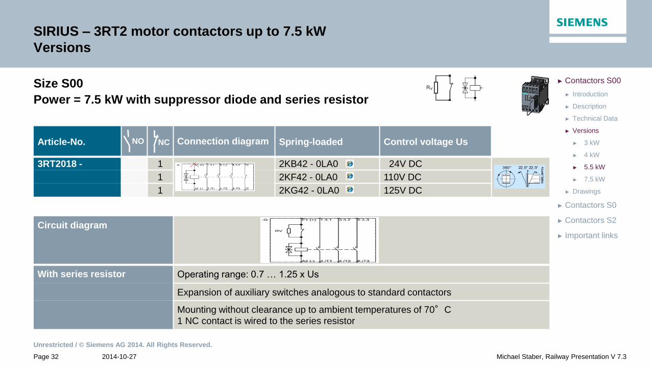
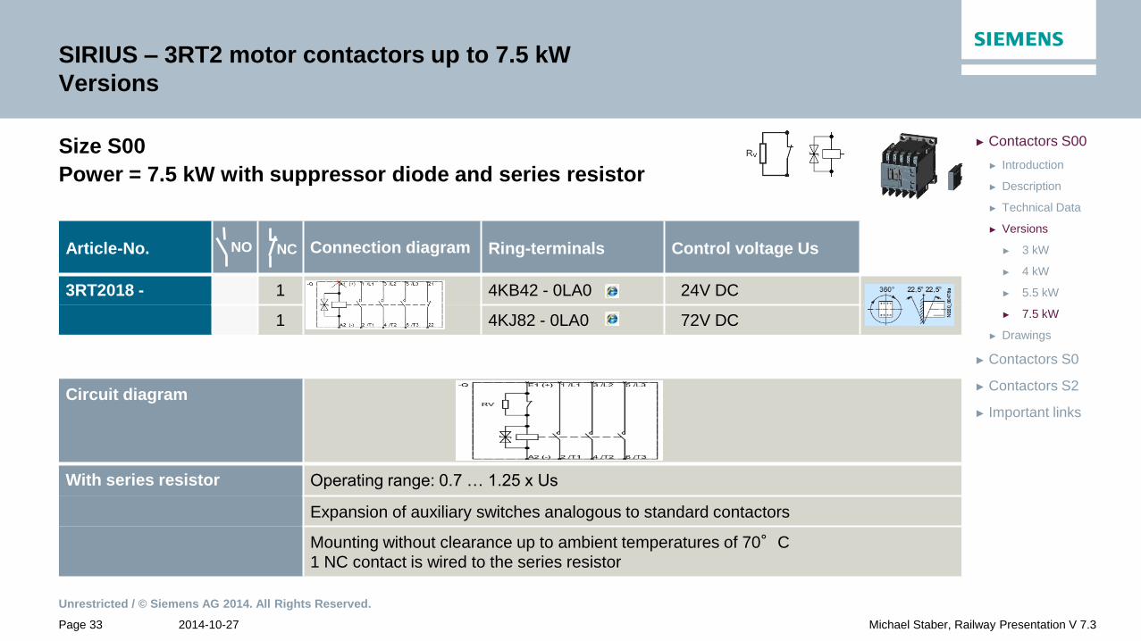
Size S00
Power = 7.5 kW with suppressor diode and series resistor
Article-No. Connection diagram Spring-loaded Control voltage Us
3RT2018 - 1 2KB42 - 0LA0 24V DC
1 2KF42 - 0LA0 110V DC
1 2KG42 - 0LA0 125V DC
NO NC
Circuit diagram
With series resistor Operating range: 0.7 … 1.25 x Us
Expansion of auxiliary switches analogous to standard contactors
Mounting without clearance up to ambient temperatures of 70°C
1 NC contact is wired to the series resistor
Unrestricted / © Siemens AG 2014. All Rights Reserved.
2014-10-27 Page 33 Michael Staber, Railway Presentation V 7.3
► Important links
► Contactors S2
► Contactors S0
► Drawings
► 7.5 kW
► 5.5 kW
► 4 kW
► 3 kW
► Versions
► Technical Data
► Description
► Introduction
► Contactors S00
SIRIUS – 3RT2 motor contactors up to 7.5 kW
Versions
Size S00
Power = 7.5 kW with suppressor diode and series resistor
Article-No. Connection diagram Ring-terminals Control voltage Us
3RT2018 - 1 4KB42 - 0LA0 24V DC
1 4KJ82 - 0LA0 72V DC
NO NC
Circuit diagram
With series resistor Operating range: 0.7 … 1.25 x Us
Expansion of auxiliary switches analogous to standard contactors
Mounting without clearance up to ambient temperatures of 70°C
1 NC contact is wired to the series resistor

Unrestricted / © Siemens AG 2014. All Rights Reserved.
2014-10-27 Page 34 Michael Staber, Railway Presentation V 7.3
► Important links
► Contactors S2
► Contactors S0
► Drawings
► 7.5 kW
► 5.5 kW
► 4 kW
► 3 kW
► Versions
► Technical Data
► Description
► Introduction
► Contactors S00
SIRIUS – 3RT2 motor contactors up to 7.5 kW
Versions
Size S00
Power = 7.5 kW with suppressor diode and series resistor
Article-No. Connection diagram Spring-loaded Control voltage Us
3RT2018 - 1 2LB42 - 0LA0 24V DC
1 2LJ82 - 0LA0 72V DC
1 2LF42 - 0LA0 110V DC
NO NC
Circuit diagram
With series resistor Operating range: 0.7 … 1.25 x Us
Expansion of auxiliary switches analogous to standard contactors
Mounting without clearance up to ambient temperatures of 70°C
1 NC contact is wired to the series resistor
Unrestricted / © Siemens AG 2014. All Rights Reserved.
2014-10-27 Page 35 Michael Staber, Railway Presentation V 7.3
► Important links
► Contactors S2
► Contactors S0
► Drawings
► 7.5 kW
► 5.5 kW
► 4 kW
► 3 kW
► Versions
► Technical Data
► Description
► Introduction
► Contactors S00
SIRIUS – 3RT2 motor contactors up to 7.5 kW
Versions
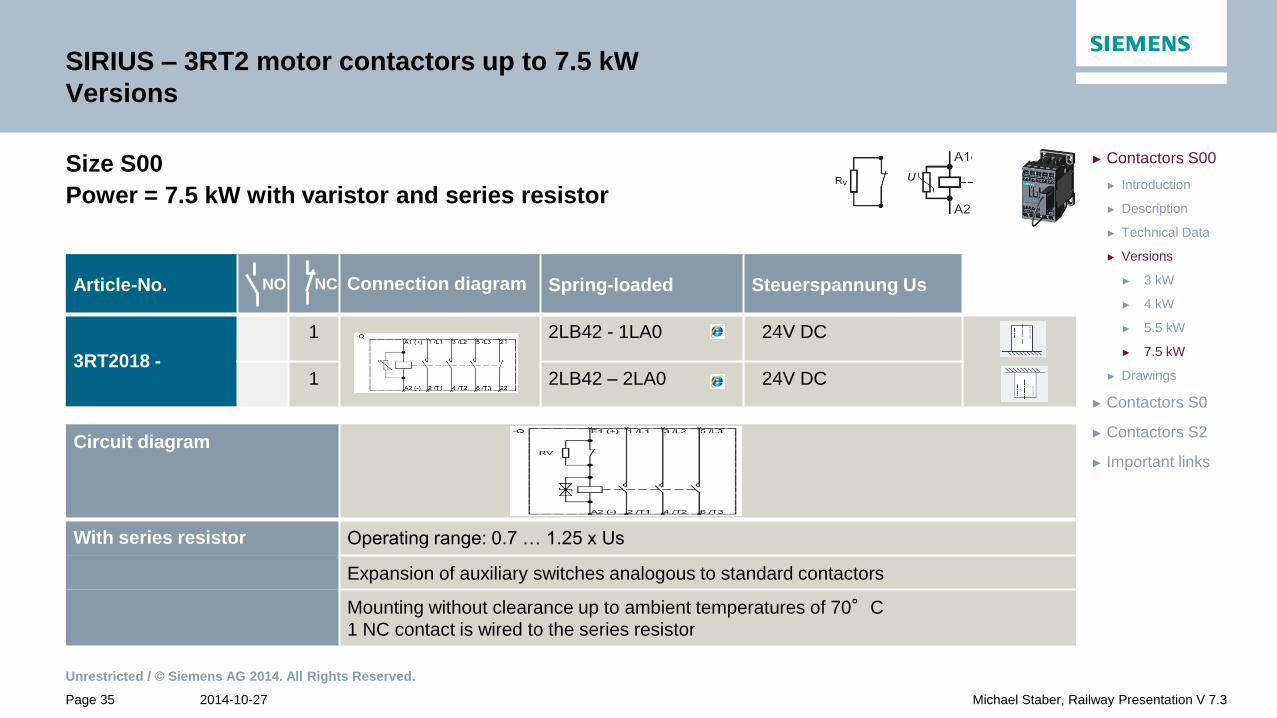
Size S00
Power = 7.5 kW with varistor and series resistor
NO NC
Circuit diagram
With series resistor Operating range: 0.7 … 1.25 x Us
Expansion of auxiliary switches analogous to standard contactors
Mounting without clearance up to ambient temperatures of 70°C
1 NC contact is wired to the series resistor
Article-No. Connection diagram Spring-loaded Steuerspannung Us
3RT2018 -
1 2LB42 - 1LA0 24V DC
1 2LB42 – 2LA0 24V DC
NO NC

Unrestricted / © Siemens AG 2014. All Rights Reserved.
2014-10-27 Page 36 Michael Staber, Railway Presentation V 7.3
► Important links
► Contactors S2
► Contactors S0
► Drawings
► 7.5 kW
► 5.5 kW
► 4 kW
► 3 kW
► Versions
► Technical Data
► Description
► Introduction
► Contactors S00
SIRIUS – 3RT2 motor contactors up to 7.5 kW
Versions
Size S00
Power = 7.5 kW with varistor and series resistor
Article-No. Connection diagram Ring-terminals Control voltage Us
3RT2018 - 1 4LB42 - 0LA0 24V DC
NO NC
Circuit diagram
With series resistor Operating range: 0.7 … 1.25 x Us
Expansion of auxiliary switches analogous to standard contactors
Mounting without clearance up to ambient temperatures of 70°C
1 NC contact is wired to the series resistor
Unrestricted / © Siemens AG 2014. All Rights Reserved.
2014-10-27 Page 37 Michael Staber, Railway Presentation V 7.3
► Important links
► Contactors S2
► Contactors S0
► Drawings
► Versions
► Technical Data
► Description
► Introduction
► Contactors S00
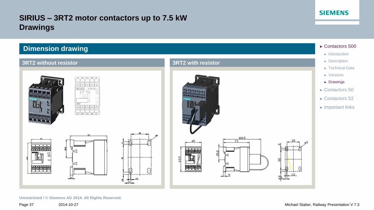
SIRIUS – 3RT2 motor contactors up to 7.5 kW
Drawings
Dimension drawing
3RT2 with resistor 3RT2 without resistor

Unrestricted / © Siemens AG 2014. All Rights Reserved.
2014-10-27 Page 38 Michael Staber, Railway Presentation V 7.3
► Important links
► Contactors S2
► Drawings
► Versions
► Technical Data
► Description
► Introduction
► Contactors S0
► Contactors S00
SIRIUS – 3RT2 motor contactors up to 18.5 kW
Introduction
Contactors S0

Unrestricted / © Siemens AG 2014. All Rights Reserved.
2014-10-27 Page 39 Michael Staber, Railway Presentation V 7.3
► Important links
► Contactors S2
► Drawings
► Versions
► Technical Data
► Description
► Introduction
► Contactors S0
► Contactors S00
SIRIUS – 3RT2 motor contactors up to 18.5 kW
Description
Contactors S0
• Spring-loaded and screw-type connection system on all terminals
(also ring cable lug connection upon request)
• Coil with suppressor diode or varistor circuit
• For screw and snap-on mounting on DIN rail
• Extended coil operating range: 0.7 – 1.25 x Us
• Communication via IO-Link with stationary applications
• Mounting:
• With resistor/ electronic coil: clearance up to ambient temperatures
of 70 °C is not required
• Without resistor: minimum lateral clearance of 10mm for ambient
temperatures exceeding 60 °C
• Auxiliaries:
• With resistor/ electronic coil: the addition of contact blocks is
allowed
• Without resistor: the addition of auxiliary contact blocks is not
allowed
Description

Unrestricted / © Siemens AG 2014. All Rights Reserved.
2014-10-27 Page 40 Michael Staber, Railway Presentation V 7.3
► Important links
► Contactors S2
► Drawings
► Versions
► Technical Data
► Description
► Introduction
► Contactors S0
► Contactors S00
SIRIUS – 3RT2 motor contactors up to 18.5 kW
Technical Data
Contactors S0
Standard coil With solid-state operating
mechanism
Currents
[A]
1 conducting path
Ie DC-1 / 24V
Ie DC-1 / 110V
35
4.5
Ie DC-3 / 24V
Ie DC-3 / 110V
20
2.5
Coil power
[W]
Closing
Holding
4.5
4.5
6.7
0.8
Weight [ kg / PE ] 0.58 / 0.60 0.58

Unrestricted / © Siemens AG 2014. All Rights Reserved.
2014-10-27 Page 41 Michael Staber, Railway Presentation V 7.3
► Important links
► Contactors S2
► Drawings
► 18.5 kW
► 15 kW
► 11 kW 4-pole
► 11 kW
► 7.5 kW
► 5.5 kW
► 4 kW
► Versions
► Technical Data
► Description
► Introduction
► Contactors S0
► Contactors S00
SIRIUS – 3RT2 motor contactors up to 18.5 kW
Versions
Size S0
Power = 4 kW with varistor
Article-No. Connection diagram Screw-type Spring-loaded Voltage Us
3RT2023 - 1 1 1KB40 2KB40 24V DC
NO NC
Without series resistor Operating range: 0.7 … 1.25 x Us
No attachment option for auxiliary switches
A clearance of 10 mm is required for side-by-side mounting at ambient temperatures
>60°C
Unrestricted / © Siemens AG 2014. All Rights Reserved.
2014-10-27 Page 42 Michael Staber, Railway Presentation V 7.3
► Important links
► Contactors S2
► Drawings
► 18.5 kW
► 15 kW
► 11 kW 4-pole
► 11 kW
► 7.5 kW
► 5.5 kW
► 4 kW
► Versions
► Technical Data
► Description
► Introduction
► Contactors S0
► Contactors S00
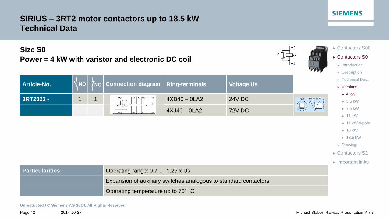
SIRIUS – 3RT2 motor contactors up to 18.5 kW
Technical Data
Size S0
Power = 4 kW with varistor and electronic DC coil
Article-No. Connection diagram Ring-terminals Voltage Us
3RT2023 - 1 1 4XB40 – 0LA2 24V DC
4XJ40 – 0LA2 72V DC
Particularities Operating range: 0.7 … 1.25 x Us
Expansion of auxiliary switches analogous to standard contactors
Operating temperature up to 70°C
NO NC

Unrestricted / © Siemens AG 2014. All Rights Reserved.
2014-10-27 Page 43 Michael Staber, Railway Presentation V 7.3
► Important links
► Contactors S2
► Drawings
► 18.5 kW
► 15 kW
► 11 kW 4-pole
► 11 kW
► 7.5 kW
► 5.5 kW
► 4 kW
► Versions
► Technical Data
► Description
► Introduction
► Contactors S0
► Contactors S00
SIRIUS – 3RT2 motor contactors up to 18.5 kW
Versions
Size S0
Power = 5.5 kW with varistor
Article-No. Connection diagram Screw-type Spring-loaded Voltage Us
3RT2024 - 1 1 1KB40 2KB40 24V DC
NO NC
Without series resistor Operating range: 0.7 … 1.25 x Us
No attachment option for auxiliary switches
A clearance of 10 mm is required for side-by-side mounting at ambient temperatures
>60°C
Unrestricted / © Siemens AG 2014. All Rights Reserved.
2014-10-27 Page 44 Michael Staber, Railway Presentation V 7.3
► Important links
► Contactors S2
► Drawings
► 18.5 kW
► 15 kW
► 11 kW 4-pole
► 11 kW
► 7.5 kW
► 5.5 kW
► 4 kW
► Versions
► Technical Data
► Description
► Introduction
► Contactors S0
► Contactors S00
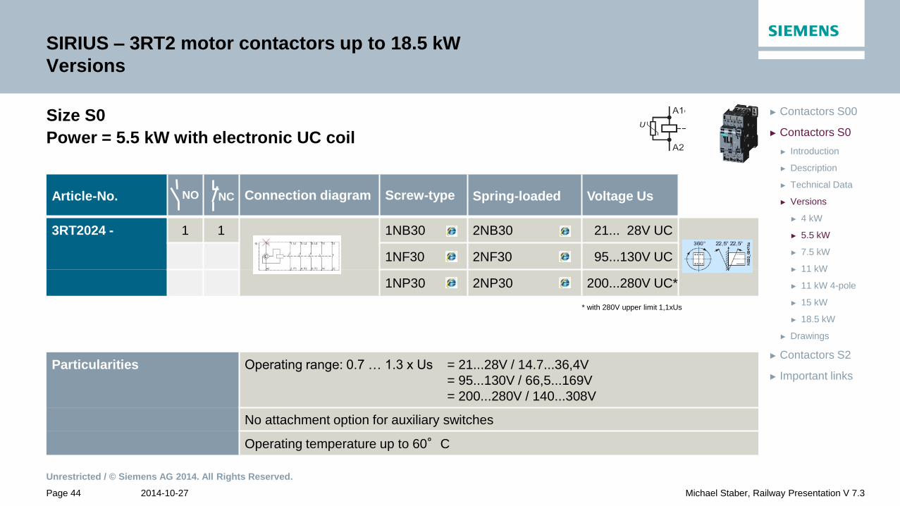
SIRIUS – 3RT2 motor contactors up to 18.5 kW
Versions
Size S0
Power = 5.5 kW with electronic UC coil
* with 280V upper limit 1,1xUs
Article-No. Connection diagram Screw-type Spring-loaded Voltage Us
3RT2024 - 1 1 1NB30 2NB30 21... 28V UC
1NF30 2NF30 95...130V UC
1NP30 2NP30 200...280V UC*
Particularities Operating range: 0.7 … 1.3 x Us = 21...28V / 14.7...36,4V
= 95...130V / 66,5...169V
= 200...280V / 140...308V
No attachment option for auxiliary switches
Operating temperature up to 60°C
NO NC

Unrestricted / © Siemens AG 2014. All Rights Reserved.
2014-10-27 Page 45 Michael Staber, Railway Presentation V 7.3
► Important links
► Contactors S2
► Drawings
► 18.5 kW
► 15 kW
► 11 kW 4-pole
► 11 kW
► 7.5 kW
► 5.5 kW
► 4 kW
► Versions
► Technical Data
► Description
► Introduction
► Contactors S0
► Contactors S00
SIRIUS – 3RT2 motor contactors up to 18.5 kW
Versions
Size S0
Power = 5.5 kW with varistor and electronic DC coil
Article-No. Connection diagram Spring-loaded Voltage Us
3RT2024 - 1 1 2XJ40 – 0LA2 72V DC
NO NC
Particularities Operating range: 0.7 … 1.25 x Us
Expansion of auxiliary switches analogous to standard contactors
Operating temperature up to 70°C

Unrestricted / © Siemens AG 2014. All Rights Reserved.
2014-10-27 Page 46 Michael Staber, Railway Presentation V 7.3
► Important links
► Contactors S2
► Drawings
► 18.5 kW
► 15 kW
► 11 kW 4-pole
► 11 kW
► 7.5 kW
► 5.5 kW
► 4 kW
► Versions
► Technical Data
► Description
► Introduction
► Contactors S0
► Contactors S00
SIRIUS – 3RT2 motor contactors up to 18.5 kW
Versions
Size S0
Power = 5.5 kW with varistor and electronic DC coil
Article-No. Connection diagram Ring-terminals Voltage Us
3RT2024 - 1 1 4XB40 – 0LA2 24V DC
4XJ40 – 0LA2 72V DC
Particularities Operating range: 0.7 … 1.25 x Us
Expansion of auxiliary switches analogous to standard contactors
Operating temperature up to 70°C
NO NC

Unrestricted / © Siemens AG 2014. All Rights Reserved.
2014-10-27 Page 47 Michael Staber, Railway Presentation V 7.3
► Important links
► Contactors S2
► Drawings
► 18.5 kW
► 15 kW
► 11 kW 4-pole
► 11 kW
► 7.5 kW
► 5.5 kW
► 4 kW
► Versions
► Technical Data
► Description
► Introduction
► Contactors S0
► Contactors S00
SIRIUS – 3RT2 motor contactors up to 18.5 kW
Versions
Size S0
Power = 7.5 kW with varistor
Article-No. Connection diagram Screw-type Spring-loaded Voltage Us
3RT2025 - 1 1 1KB40 2KB40 24V DC
2KF40 110V DC
2KG40 125V DC
NO NC
Particularities Operating range: 0.7 … 1.25 x Us
No attachment option for auxiliary switches
A clearance of 10 mm is required for side-by-side mounting at ambient temperatures
>60°C

Unrestricted / © Siemens AG 2014. All Rights Reserved.
2014-10-27 Page 48 Michael Staber, Railway Presentation V 7.3
► Important links
► Contactors S2
► Drawings
► 18.5 kW
► 15 kW
► 11 kW 4-pole
► 11 kW
► 7.5 kW
► 5.5 kW
► 4 kW
► Versions
► Technical Data
► Description
► Introduction
► Contactors S0
► Contactors S00
SIRIUS – 3RT2 motor contactors up to 18.5 kW
Versions
Size S0
Power = 7.5 kW with varistor
Article-No. Connection diagram Ring-terminals Voltage Us
3RT2025 - 1 1 4KB40 24V DC
4KJ40 72V DC
NO NC
Particularities Operating range: 0.7 … 1.25 x Us
No attachment option for auxiliary switches
A clearance of 10 mm is required for side-by-side mounting at ambient temperatures
>60°C

Unrestricted / © Siemens AG 2014. All Rights Reserved.
2014-10-27 Page 49 Michael Staber, Railway Presentation V 7.3
► Important links
► Contactors S2
► Drawings
► 18.5 kW
► 15 kW
► 11 kW 4-pole
► 11 kW
► 7.5 kW
► 5.5 kW
► 4 kW
► Versions
► Technical Data
► Description
► Introduction
► Contactors S0
► Contactors S00
SIRIUS – 3RT2 motor contactors up to 18.5 kW
Versions
Size S0
Power = 7.5 kW with electronic UC coil
* with 280V upper limit 1,1xUs
Article-No. Connection diagram Screw-type Spring-loaded Voltage Us
3RT2025 - 1 1 1NB30 2NB30 21... 28V UC
1NF30 2NF30 95...130V UC
1NP30 2NP30 200...280V UC*
NO NC
Particularities Operating range: 0.7 … 1.3 x Us = 21...28V / 14.7...36,4V
= 95...130V / 66,5...169V
= 200...280V / 140...308V
No attachment option for auxiliary switches
Operating temperature up to 60°C

Unrestricted / © Siemens AG 2014. All Rights Reserved.
2014-10-27 Page 50 Michael Staber, Railway Presentation V 7.3
► Important links
► Contactors S2
► Drawings
► 18.5 kW
► 15 kW
► 11 kW 4-pole
► 11 kW
► 7.5 kW
► 5.5 kW
► 4 kW
► Versions
► Technical Data
► Description
► Introduction
► Contactors S0
► Contactors S00
SIRIUS – 3RT2 motor contactors up to 18.5 kW
Versions
Size S0
Power = 7.5 kW with varistor and electronic DC coil
Article-No. Connection diagram Spring-loaded Voltage Us
3RT2025 - 1 1 2XB40 – 0LA2 24V DC
2XF40 – 0LA2 110V DC
2XG40 – 0LA2 125V DC
Particularities Operating range: 0.7 … 1.25 x Us
Expansion of auxiliary switches analogous to standard contactors
Operating temperature up to 70°C
NO NC

Unrestricted / © Siemens AG 2014. All Rights Reserved.
2014-10-27 Page 51 Michael Staber, Railway Presentation V 7.3
► Important links
► Contactors S2
► Drawings
► 18.5 kW
► 15 kW
► 11 kW 4-pole
► 11 kW
► 7.5 kW
► 5.5 kW
► 4 kW
► Versions
► Technical Data
► Description
► Introduction
► Contactors S0
► Contactors S00
SIRIUS – 3RT2 motor contactors up to 18.5 kW
Versions
Size S0
Power = 7.5 kW with varistor and electronic DC coil
Article-No. Connection diagram Ring-terminals Voltage Us
3RT2025 - 1 1 4XB40 – 0LA2 24V DC
4XJ40 – 0LA2 72V DC
NO NC
Particularities Operating range: 0.7 … 1.25 x Us
Expansion of auxiliary switches analogous to standard contactors
Operating temperature up to 70°C

Unrestricted / © Siemens AG 2014. All Rights Reserved.
2014-10-27 Page 52 Michael Staber, Railway Presentation V 7.3
► Important links
► Contactors S2
► Drawings
► 18.5 kW
► 15 kW
► 11 kW 4-pole
► 11 kW
► 7.5 kW
► 5.5 kW
► 4 kW
► Versions
► Technical Data
► Description
► Introduction
► Contactors S0
► Contactors S00
SIRIUS – 3RT2 motor contactors up to 18.5 kW
Versions
Size S0
Power = 7.5 kW with varistor and electronic DC coil
Article-No. Connection diagram Spring-loaded Voltage Us
3RT2025 - 1 1 2XF40 – 1LA2 110V DC
NO NC
Particularities Operating range: 0.7 … 1.25 x Us
Expansion of auxiliary switches analogous to standard contactors
Operating temperature up to 70°C

Unrestricted / © Siemens AG 2014. All Rights Reserved.
2014-10-27 Page 53 Michael Staber, Railway Presentation V 7.3
► Important links
► Contactors S2
► Drawings
► 18.5 kW
► 15 kW
► 11 kW 4-pole
► 11 kW
► 7.5 kW
► 5.5 kW
► 4 kW
► Versions
► Technical Data
► Description
► Introduction
► Contactors S0
► Contactors S00
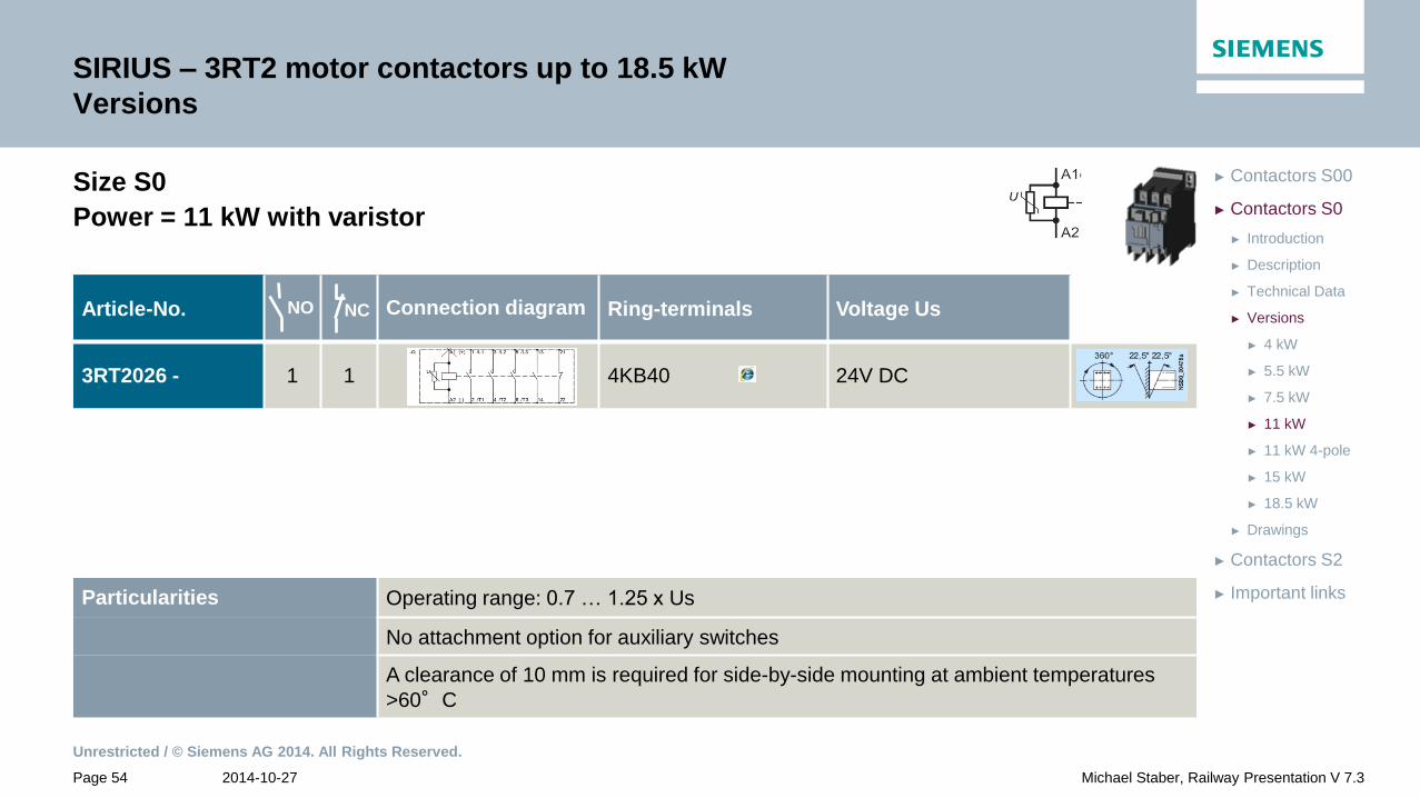
SIRIUS – 3RT2 motor contactors up to 18.5 kW
Versions
Size S0
Power = 11 kW with varistor
Article-No. Connection diagram Screw-type Spring-loaded Voltage Us
3RT2026 - 1 1 2KA40 12V DC
1KB40 2KB40 24V DC
2KF40 110V DC
2KG40 125V DC
NO NC
Particularities Operating range: 0.7 … 1.25 x Us
No attachment option for auxiliary switches
A clearance of 10 mm is required for side-by-side mounting at ambient temperatures
>60°C
Unrestricted / © Siemens AG 2014. All Rights Reserved.
2014-10-27 Page 54 Michael Staber, Railway Presentation V 7.3
► Important links
► Contactors S2
► Drawings
► 18.5 kW
► 15 kW
► 11 kW 4-pole
► 11 kW
► 7.5 kW
► 5.5 kW
► 4 kW
► Versions
► Technical Data
► Description
► Introduction
► Contactors S0
► Contactors S00
SIRIUS – 3RT2 motor contactors up to 18.5 kW
Versions
Size S0
Power = 11 kW with varistor
Article-No. Connection diagram Ring-terminals Voltage Us
3RT2026 - 1 1 4KB40 24V DC
NO NC
Particularities Operating range: 0.7 … 1.25 x Us
No attachment option for auxiliary switches
A clearance of 10 mm is required for side-by-side mounting at ambient temperatures
>60°C

Unrestricted / © Siemens AG 2014. All Rights Reserved.
2014-10-27 Page 55 Michael Staber, Railway Presentation V 7.3
► Important links
► Contactors S2
► Drawings
► 18.5 kW
► 15 kW
► 11 kW 4-pole
► 11 kW
► 7.5 kW
► 5.5 kW
► 4 kW
► Versions
► Technical Data
► Description
► Introduction
► Contactors S0
► Contactors S00
SIRIUS – Motorschütze 3RT2 bis 18,5 kw
Ausführungen
Size S0
Power = 11 kW with diode combination
Article-No. Connection diagram Ring-terminals Voltage Us
3RT2026 - 1 1 4VB40 24V DC
S Ö
Particularities Operating range: 0.7 … 1.25 x Us
No expansion option for auxiliary switches
A clearance of 10 mm is required for side-by-side mounting at ambient temperatures
>60°C

Unrestricted / © Siemens AG 2014. All Rights Reserved.
2014-10-27 Page 56 Michael Staber, Railway Presentation V 7.3
► Important links
► Contactors S2
► Drawings
► 18.5 kW
► 15 kW
► 11 kW 4-pole
► 11 kW
► 7.5 kW
► 5.5 kW
► 4 kW
► Versions
► Technical Data
► Description
► Introduction
► Contactors S0
► Contactors S00
SIRIUS – 3RT2 motor contactors up to 18.5 kW
Versions
Size S0
Power = 11 kW with electronic UC coil
* with 280V upper limit 1,1xUs
Article-No. Connection diagram Screw-type Spring-loaded Voltage Us
3RT2026 - 1 1 1NB30 2NB30 21... 28V UC
1 1 1NF30 2NF30 95...130V UC
1 1 1NP30 2NP30 200...280V UC*
NO NC
Particularities Operating range: 0.7 … 1.3 x Us = 21...28V / 14.7...36,4V
= 95...130V / 66,5...169V
= 200...280V / 140...308V
No attachment option for auxiliary switches
Operating temperature up to 60°C

Unrestricted / © Siemens AG 2014. All Rights Reserved.
2014-10-27 Page 57 Michael Staber, Railway Presentation V 7.3
► Important links
► Contactors S2
► Drawings
► 18.5 kW
► 15 kW
► 11 kW 4-pole
► 11 kW
► 7.5 kW
► 5.5 kW
► 4 kW
► Versions
► Technical Data
► Description
► Introduction
► Contactors S0
► Contactors S00
Particularities Operating range: 0.7 … 1.25 x Us
Expansion of auxiliary switches analogous to standard contactors
Operating temperature up to 70°C
SIRIUS – 3RT2 motor contactors up to 18.5 kW
Versions
Size S0
Power = 11 kW with varistor and electronic DC coil
Article-No. Connection diagram Spring-loaded Voltage Us
3RT2026 - 1 1 2XB40 – 0LA2 24V DC
1 1 2XJ40 – 0LA2 72V DC
1 1 2XF40 – 0LA2 110V DC
1 1 2XG40 – 0LA2 125V DC
NO NC
Unrestricted / © Siemens AG 2014. All Rights Reserved.
2014-10-27 Page 58 Michael Staber, Railway Presentation V 7.3
► Important links
► Contactors S2
► Drawings
► 18.5 kW
► 15 kW
► 11 kW 4-pole
► 11 kW
► 7.5 kW
► 5.5 kW
► 4 kW
► Versions
► Technical Data
► Description
► Introduction
► Contactors S0
► Contactors S00
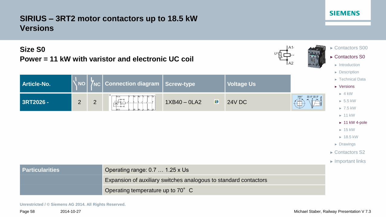
SIRIUS – 3RT2 motor contactors up to 18.5 kW
Versions
Size S0
Power = 11 kW with varistor and electronic UC coil
Article-No. Connection diagram Screw-type Voltage Us
3RT2026 - 2 2 1XB40 – 0LA2 24V DC
NO NC
Particularities Operating range: 0.7 … 1.25 x Us
Expansion of auxiliary switches analogous to standard contactors
Operating temperature up to 70°C

Unrestricted / © Siemens AG 2014. All Rights Reserved.
2014-10-27 Page 59 Michael Staber, Railway Presentation V 7.3
► Important links
► Contactors S2
► Drawings
► 18.5 kW
► 15 kW
► 11 kW 4-pole
► 11 kW
► 7.5 kW
► 5.5 kW
► 4 kW
► Versions
► Technical Data
► Description
► Introduction
► Contactors S0
► Contactors S00
SIRIUS – 3RT2 motor contactors up to 18.5 kW
Versions
Size S0
Power = 11 kW with varistor and electronic DC coil
Article-No. Connection diagram Ring-terminals Voltage Us
3RT2026 - 1 1 4XB40 – 0LA2 24V DC
NO NC
Particularities Operating range: 0.7 … 1.25 x Us
Expansion of auxiliary switches analogous to standard contactors
Operating temperature up to 70°C

Unrestricted / © Siemens AG 2014. All Rights Reserved.
2014-10-27 Page 60 Michael Staber, Railway Presentation V 7.3
► Important links
► Contactors S2
► Drawings
► 18.5 kW
► 15 kW
► 11 kW 4-pole
► 11 kW
► 7.5 kW
► 5.5 kW
► 4 kW
► Versions
► Technical Data
► Description
► Introduction
► Contactors S0
► Contactors S00
SIRIUS – 3RT2 motor contactors up to 18.5 kW
Versions
Size S0
Power = 11 kW with varistor and electronic DC coil
Article-No. Connection diagram Spring-loaded Voltage Us
3RT2026 - 1 1 2XB40 – 1LA2 24V DC
NO NC
Particularities Operating range: 0.7 … 1.25 x Us
Expansion of auxiliary switches analogous to standard contactors
Operating temperature up to 70°C

Unrestricted / © Siemens AG 2014. All Rights Reserved.
2014-10-27 Page 61 Michael Staber, Railway Presentation V 7.3
► Important links
► Contactors S2
► Drawings
► 18.5 kW
► 15 kW
► 11 kW 4-pole
► 11 kW
► 7.5 kW
► 5.5 kW
► 4 kW
► Versions
► Technical Data
► Description
► Introduction
► Contactors S0
► Contactors S00
SIRIUS – 3RT2 motor contactors up to 18.5 kW
Versions
Size S0
Power = 11 kW with varistor and electronic DC coil
Article-No. Connection diagram Spring-loaded Voltage Us
3RT2326 - 1 1 2XB40 – 0LA2 24V DC
S Ö
Particularities Operating range: 0.7 … 1.25 x Us
Expansion of auxiliary switches analogous to standard contactors
Operating temperature up to 70°C
Unrestricted / © Siemens AG 2014. All Rights Reserved.
2014-10-27 Page 62 Michael Staber, Railway Presentation V 7.3
► Important links
► Contactors S2
► Drawings
► 18.5 kW
► 15 kW
► 11 kW 4-pole
► 11 kW
► 7.5 kW
► 5.5 kW
► 4 kW
► Versions
► Technical Data
► Description
► Introduction
► Contactors S0
► Contactors S00
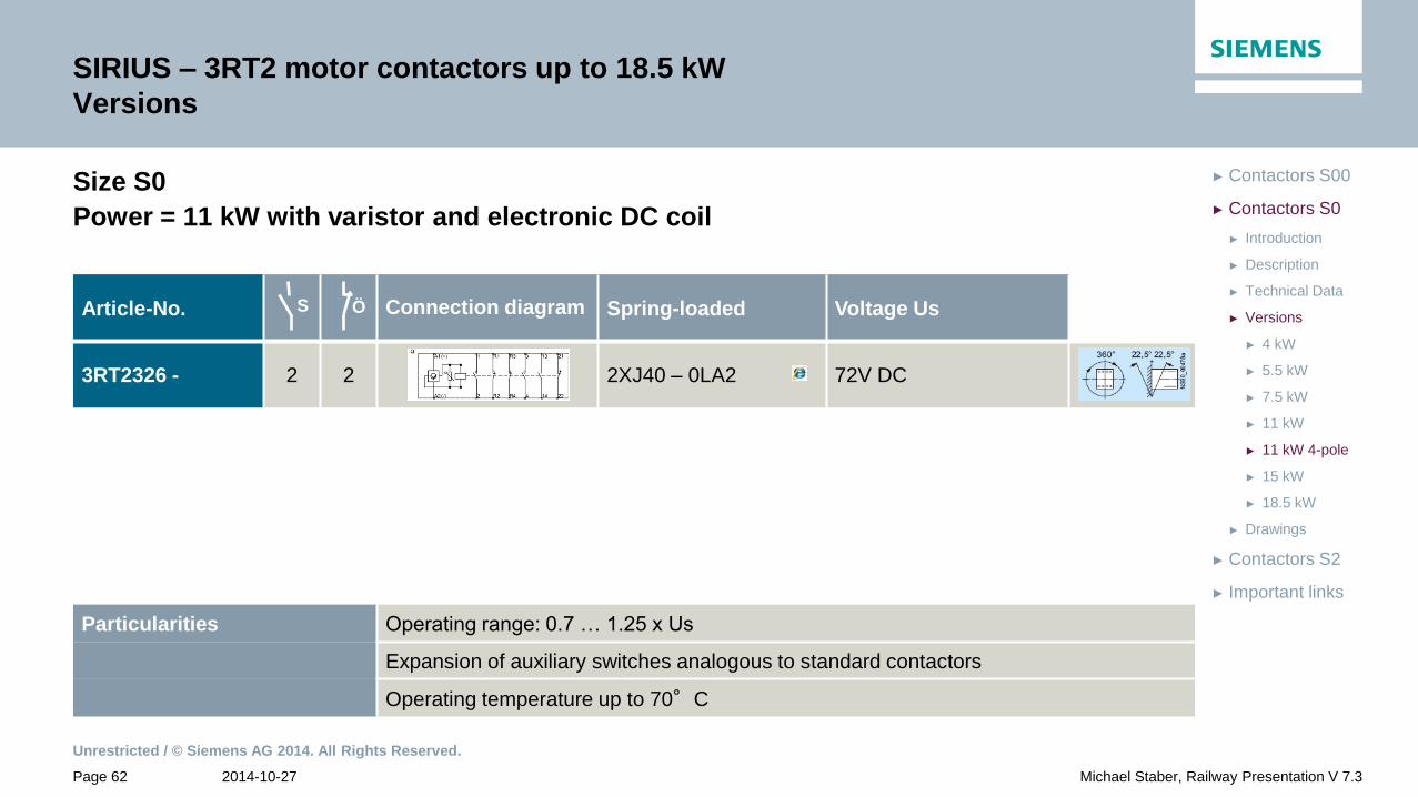
SIRIUS – 3RT2 motor contactors up to 18.5 kW
Versions
Size S0
Power = 11 kW with varistor and electronic DC coil
Article-No. Connection diagram Spring-loaded Voltage Us
3RT2326 - 2 2 2XJ40 – 0LA2 72V DC
S Ö
Particularities Operating range: 0.7 … 1.25 x Us
Expansion of auxiliary switches analogous to standard contactors
Operating temperature up to 70°C

Unrestricted / © Siemens AG 2014. All Rights Reserved.
2014-10-27 Page 63 Michael Staber, Railway Presentation V 7.3
► Important links
► Contactors S2
► Drawings
► 18.5 kW
► 15 kW
► 11 kW 4-pole
► 11 kW
► 7.5 kW
► 5.5 kW
► 4 kW
► Versions
► Technical Data
► Description
► Introduction
► Contactors S0
► Contactors S00
SIRIUS – 3RT2 motor contactors up to 18.5 kW
Versions
Size S0
Power = 15 kW with varistor
Article-No. Connection diagram Screw-type Spring-loaded Voltage Us
3RT2027 - 1 1 2KA40 12V DC
1KB40 2KB40 24V DC
2KF40 110V DC
2KG40 125V DC
NO NC
Particularities Operating range: 0.7 … 1.25 x Us
No expansion option for auxiliary switches
A clearance of 10 mm is required for side-by-side mounting at ambient temperatures
>60°C

Unrestricted / © Siemens AG 2014. All Rights Reserved.
2014-10-27 Page 64 Michael Staber, Railway Presentation V 7.3
► Important links
► Contactors S2
► Drawings
► 18.5 kW
► 15 kW
► 11 kW 4-pole
► 11 kW
► 7.5 kW
► 5.5 kW
► 4 kW
► Versions
► Technical Data
► Description
► Introduction
► Contactors S0
► Contactors S00
SIRIUS – 3RT2 motor contactors up to 18.5 kW
Versions
Size S0
Power = 15 kW with varistor
Article-No. Connection diagram Ring-terminals Voltage Us
3RT2027 - 1 1 4KB40 24V DC
NO NC
Particularities Operating range: 0.7 … 1.25 x Us
No expansion option for auxiliary switches
A clearance of 10 mm is required for side-by-side mounting at ambient temperatures
>60°C

Unrestricted / © Siemens AG 2014. All Rights Reserved.
2014-10-27 Page 65 Michael Staber, Railway Presentation V 7.3
► Important links
► Contactors S2
► Drawings
► 18.5 kW
► 15 kW
► 11 kW 4-pole
► 11 kW
► 7.5 kW
► 5.5 kW
► 4 kW
► Versions
► Technical Data
► Description
► Introduction
► Contactors S0
► Contactors S00
SIRIUS – 3RT2 motor contactors up to 18.5 kW
Versions
Size S0
Power = 15 kW with diode combination
Article-No. Connection diagram Ring-terminals Voltage Us
3RT2027 - 1 1 4VB40 24V DC
4VF40 110V DC
NO NC
Particularities Operating range: 0.7 … 1.25 x Us
No expansion option for auxiliary switches
A clearance of 10 mm is required for side-by-side mounting at ambient temperatures
>60°C

Unrestricted / © Siemens AG 2014. All Rights Reserved.
2014-10-27 Page 66 Michael Staber, Railway Presentation V 7.3
► Important links
► Contactors S2
► Drawings
► 18.5 kW
► 15 kW
► 11 kW 4-pole
► 11 kW
► 7.5 kW
► 5.5 kW
► 4 kW
► Versions
► Technical Data
► Description
► Introduction
► Contactors S0
► Contactors S00
SIRIUS – 3RT2 motor contactors up to 18.5 kW
Versions
Size S0
Power = 15 kW with suppressor diode and series resistor
Article-No. Connection diagram Ring-terminals Voltage Us
3RT2027 - 1 1 4KF40 - 0RB0 110V DC
Circuit diagram
Particularities Operating range: 0.7 … 1.25 x Us
Expansion of auxiliary switches analogous to standard contactors
Mounting without clearance up to ambient temperatures of 70°C
1 NC contact is wired to the series resistor
NO NC

Unrestricted / © Siemens AG 2014. All Rights Reserved.
2014-10-27 Page 67 Michael Staber, Railway Presentation V 7.3
► Important links
► Contactors S2
► Drawings
► 18.5 kW
► 15 kW
► 11 kW 4-pole
► 11 kW
► 7.5 kW
► 5.5 kW
► 4 kW
► Versions
► Technical Data
► Description
► Introduction
► Contactors S0
► Contactors S00
SIRIUS – 3RT2 motor contactors up to 18.5 kW
Versions
Size S0
Power = 15 kW with electronic UC coil
* with 280V upper limit 1,1xUs
Article-No. Connection diagram Screw-type Spring-loaded Voltage Us
3RT2027 - 1 1 1NB30 2NB30 21... 28V UC
1 1 1NF30 2NF30 95...130V UC
1 1 1NP30 2NP30 200...280V UC*
NO NC
Particularities Operating range: 0.7 … 1.3 x Us = 21...28V / 14.7...36,4V
= 95...130V / 66,5...169V
= 200...280V / 140...308V
Expansion of auxiliary switches analogous to standard contactors
Operating temperature up to 60°C
Unrestricted / © Siemens AG 2014. All Rights Reserved.
2014-10-27 Page 68 Michael Staber, Railway Presentation V 7.3
► Important links
► Contactors S2
► Drawings
► 18.5 kW
► 15 kW
► 11 kW 4-pole
► 11 kW
► 7.5 kW
► 5.5 kW
► 4 kW
► Versions
► Technical Data
► Description
► Introduction
► Contactors S0
► Contactors S00
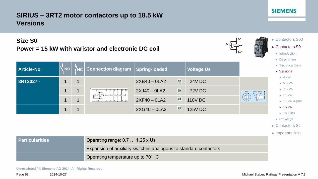
SIRIUS – 3RT2 motor contactors up to 18.5 kW
Versions
Size S0
Power = 15 kW with varistor and electronic DC coil
Article-No. Connection diagram Spring-loaded Voltage Us
3RT2027 - 1 1 2XB40 – 0LA2 24V DC
1 1 2XJ40 – 0LA2 72V DC
1 1 2XF40 – 0LA2 110V DC
1 1 2XG40 – 0LA2 125V DC
NO NC
Particularities Operating range: 0.7 … 1.25 x Us
Expansion of auxiliary switches analogous to standard contactors
Operating temperature up to 70°C
Unrestricted / © Siemens AG 2014. All Rights Reserved.
2014-10-27 Page 69 Michael Staber, Railway Presentation V 7.3
► Important links
► Contactors S2
► Drawings
► 18.5 kW
► 15 kW
► 11 kW 4-pole
► 11 kW
► 7.5 kW
► 5.5 kW
► 4 kW
► Versions
► Technical Data
► Description
► Introduction
► Contactors S0
► Contactors S00
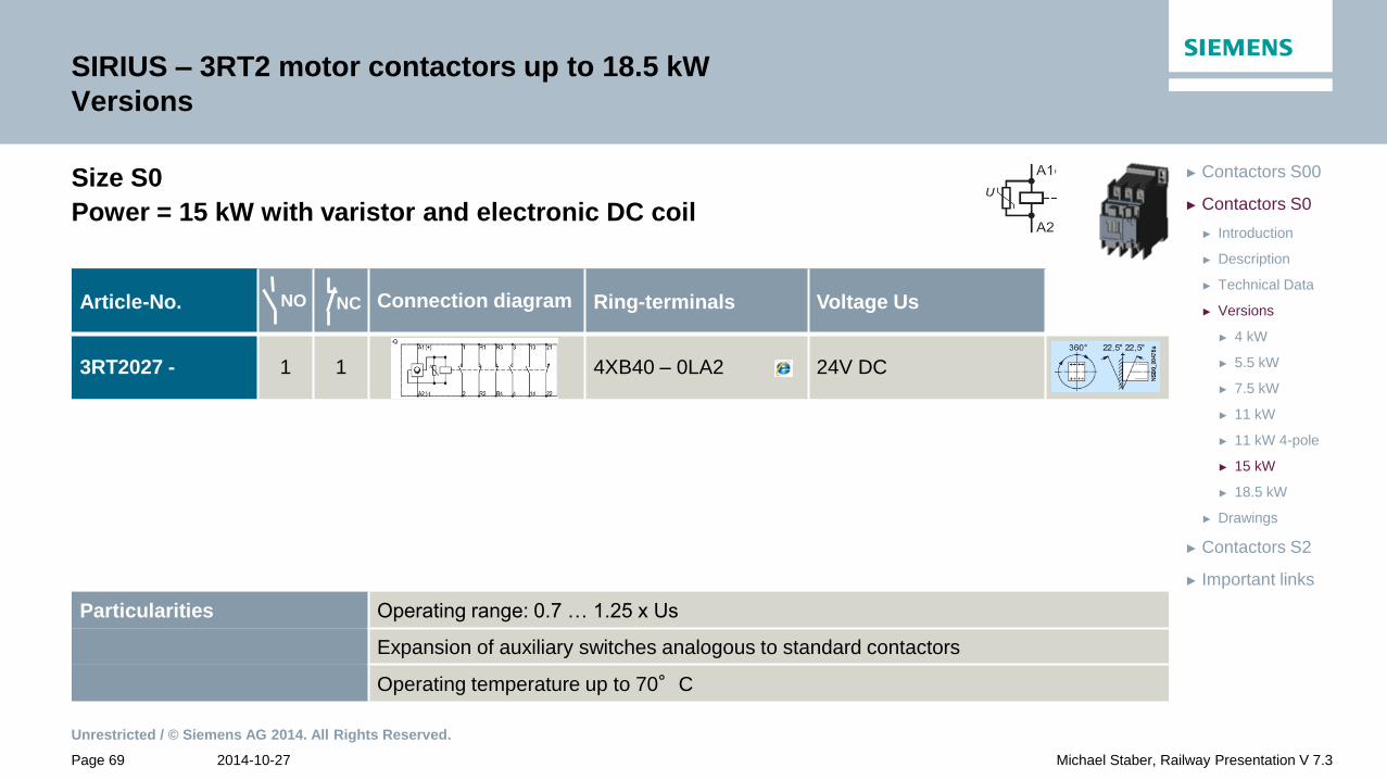
SIRIUS – 3RT2 motor contactors up to 18.5 kW
Versions
Size S0
Power = 15 kW with varistor and electronic DC coil
Article-No. Connection diagram Ring-terminals Voltage Us
3RT2027 - 1 1 4XB40 – 0LA2 24V DC
NO NC
Particularities Operating range: 0.7 … 1.25 x Us
Expansion of auxiliary switches analogous to standard contactors
Operating temperature up to 70°C
Unrestricted / © Siemens AG 2014. All Rights Reserved.
2014-10-27 Page 70 Michael Staber, Railway Presentation V 7.3
► Important links
► Contactors S2
► Drawings
► 18.5 kW
► 15 kW
► 11 kW 4-pole
► 11 kW
► 7.5 kW
► 5.5 kW
► 4 kW
► Versions
► Technical Data
► Description
► Introduction
► Contactors S0
► Contactors S00
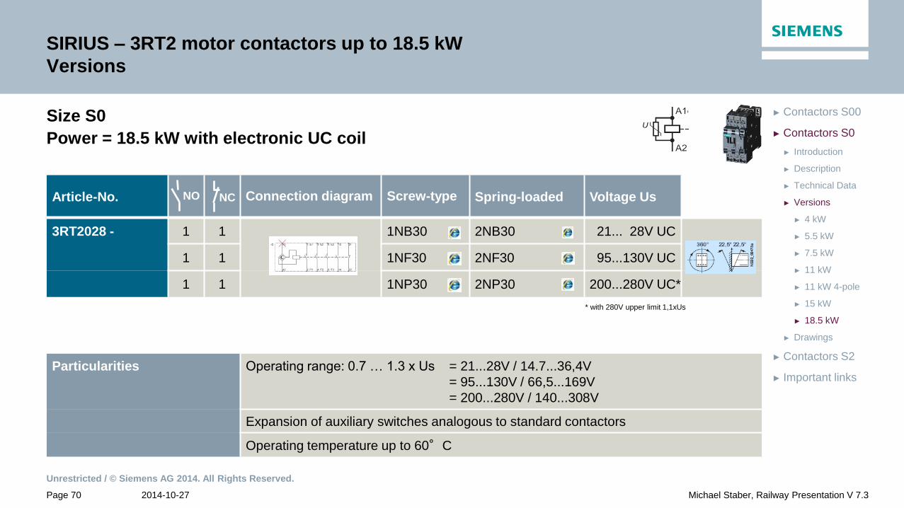
SIRIUS – 3RT2 motor contactors up to 18.5 kW
Versions
Size S0
Power = 18.5 kW with electronic UC coil
* with 280V upper limit 1,1xUs
Article-No. Connection diagram Screw-type Spring-loaded Voltage Us
3RT2028 - 1 1 1NB30 2NB30 21... 28V UC
1 1 1NF30 2NF30 95...130V UC
1 1 1NP30 2NP30 200...280V UC*
NO NC
Particularities Operating range: 0.7 … 1.3 x Us = 21...28V / 14.7...36,4V
= 95...130V / 66,5...169V
= 200...280V / 140...308V
Expansion of auxiliary switches analogous to standard contactors
Operating temperature up to 60°C

Unrestricted / © Siemens AG 2014. All Rights Reserved.
2014-10-27 Page 71 Michael Staber, Railway Presentation V 7.3
► Important links
► Contactors S2
► Drawings
► 18.5 kW
► 15 kW
► 11 kW 4-pole
► 11 kW
► 7.5 kW
► 5.5 kW
► 4 kW
► Versions
► Technical Data
► Description
► Introduction
► Contactors S0
► Contactors S00
SIRIUS – 3RT2 motor contactors up to 18.5 kW
Versions
Size S0
Power = 18.5 kW with varistor and electronic DC coil
Article-No. Connection diagram Spring-loaded Voltage Us
3RT2028 - 1 1 2XB40 – 0LA2 24V DC
1 1 2XJ40 – 0LA2 72V DC
1 1 2XF40 – 0LA2 110V DC
1 1 2XG40 – 0LA2 125V DC
NO NC
Particularities Operating range: 0.7 … 1.25 x Us
Expansion of auxiliary switches analogous to standard contactors
Operating temperature up to 70°C

Unrestricted / © Siemens AG 2014. All Rights Reserved.
2014-10-27 Page 72 Michael Staber, Railway Presentation V 7.3
► Important links
► Contactors S2
► Drawings
► 18.5 kW
► 15 kW
► 11 kW 4-pole
► 11 kW
► 7.5 kW
► 5.5 kW
► 4 kW
► Versions
► Technical Data
► Description
► Introduction
► Contactors S0
► Contactors S00
SIRIUS – 3RT2 motor contactors up to 18.5 kW
Versions
Size S0
Power = 18.5 kW with varistor and electronic DC coil
Article-No. Connection diagram Ring-terminals Voltage Us
3RT2028 - 1 1 4XB40 – 0LA2 24V DC
NO NC
Particularities Operating range: 0.7 … 1.25 x Us
Expansion of auxiliary switches analogous to standard contactors
Operating temperature up to 70°C
Unrestricted / © Siemens AG 2014. All Rights Reserved.
2014-10-27 Page 73 Michael Staber, Railway Presentation V 7.3
► Important links
► Contactors S2
► Drawings
► Versions
► Technical Data
► Description
► Introduction
► Contactors S0
► Contactors S00
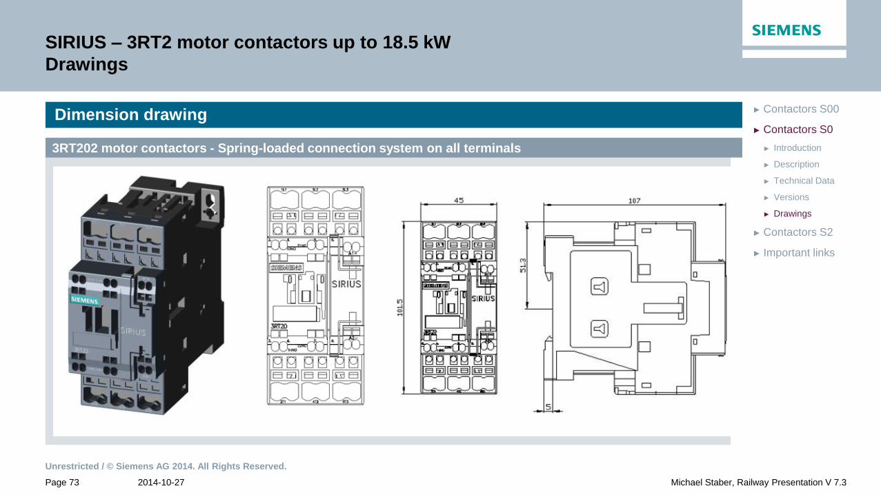
SIRIUS – 3RT2 motor contactors up to 18.5 kW
Drawings
Dimension drawing
3RT202 motor contactors - Spring-loaded connection system on all terminals
Unrestricted / © Siemens AG 2014. All Rights Reserved.
2014-10-27 Page 74 Michael Staber, Railway Presentation V 7.3
► Important links
► Contactors S2
► Drawings
► Versions
► Technical Data
► Description
► Introduction
► Contactors S0
► Contactors S00
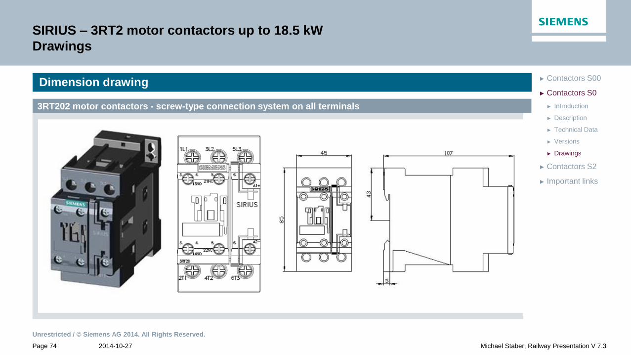
SIRIUS – 3RT2 motor contactors up to 18.5 kW
Drawings
Dimension drawing
3RT202 motor contactors - screw-type connection system on all terminals

Unrestricted / © Siemens AG 2014. All Rights Reserved.
2014-10-27 Page 75 Michael Staber, Railway Presentation V 7.3
► Important links
► Contactors S2
► Drawings
► Versions
► Technical Data
► Description
► Introduction
► Contactors S0
► Contactors S00
SIRIUS – 3RT2 motor contactors up to 18.5 kW
Drawings
3RT202 motor contactors - Ring-terminals
Dimension drawing
Unrestricted / © Siemens AG 2014. All Rights Reserved.
2014-10-27 Page 76 Michael Staber, Railway Presentation V 7.3
► Important links
► Drawings
► Versions
► Technical Data
► Description
► Introduction
► Contactors S2
► Contactors S0
► Contactors S00
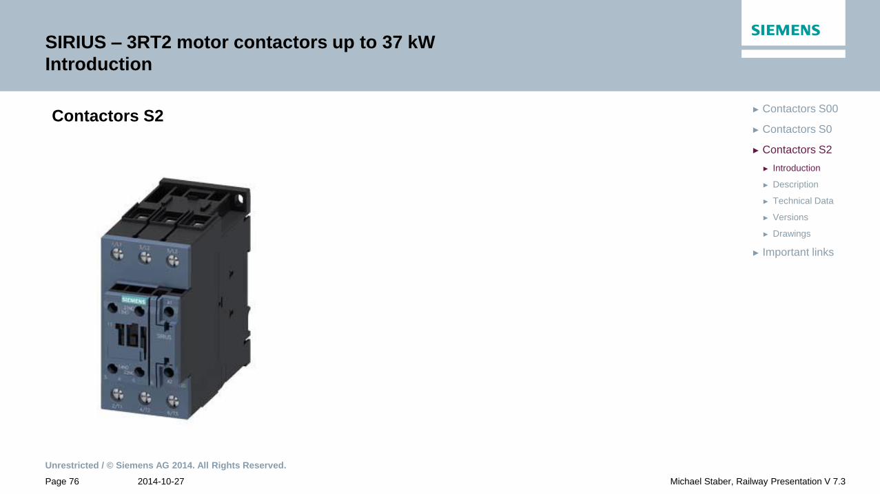
SIRIUS – 3RT2 motor contactors up to 37 kW
Introduction
Contactors S2

Unrestricted / © Siemens AG 2014. All Rights Reserved.
2014-10-27 Page 77 Michael Staber, Railway Presentation V 7.3
► Important links
► Drawings
► Versions
► Technical Data
► Description
► Introduction
► Contactors S2
► Contactors S0
► Contactors S00
SIRIUS – 3RT2 motor contactors up to 37 kW
Description
Contactors S2 Description
• Spring-loaded and screw-type connection system on all terminals
(also ring cable lug connection upon request)
• Coil with suppressor diode or varistor circuit
• For screw and snap-on mounting on DIN rail
• Extended coil operating range: 0.7 – 1.25 x Us
• Communication via IO-Link with stationary applications
• Mounting:
• With resistor/ electronic coil: clearance up to ambient temperatures
of 70 °C is not required
• Without resistor: minimum lateral clearance of 10mm for ambient
temperatures exceeding 60 °C
• Auxiliaries:
• With resistor/ electronic coil: the addition of contact blocks is
allowed
• Without resistor: the addition of auxiliary contact blocks is not
allowed

Unrestricted / © Siemens AG 2014. All Rights Reserved.
2014-10-27 Page 78 Michael Staber, Railway Presentation V 7.3
► Important links
► Drawings
► Versions
► Technical Data
► Description
► Introduction
► Contactors S2
► Contactors S0
► Contactors S00
SIRIUS – 3RT2 motor contactors up to 37 kW
Technical Data
Contactors S2
18,5kW 22kW 30kW 37kW
Currents
[A]
1 conducting path
Ie DC-1 / 24V
Ie DC-1 / 110V
55
4,5
60
4,5
70
4,5
75
4,5
Ie DC-3 / 24V
Ie DC-3 / 110V
35
2,5
35
2,5
35
2,5
35
2,5
Coil power
[W]
Einschalten
Halten
23
1
23
1
23
1
23
1
Weight [ kg / PE ] [ kg / PE ] 1,121

Unrestricted / © Siemens AG 2014. All Rights Reserved.
2014-10-27 Page 79 Michael Staber, Railway Presentation V 7.3
► Important links
► Drawings
► 37kW
► 30kW
► 20kW
► 18.5kW
► Versions
► Technical Data
► Description
► Introduction
► Contactors S2
► Contactors S0
► Contactors S00
SIRIUS – 3RT2 motor contactors up to 37 kW
Versions
Article-No. Connection diagram Screw-type Voltage Us
3RT2035 - 1 1 1XB40-0LA2 24V DC
1XF40-0LA2 110V DC
Particularities Operating range: 0.7 … 1.25 x Us
Expansion of auxiliary switches analogous to standard contactors
Operating temperature up to 70°C
NO NC
Size S2
Power = 18.5 kW with varistor

Unrestricted / © Siemens AG 2014. All Rights Reserved.
2014-10-27 Page 80 Michael Staber, Railway Presentation V 7.3
► Important links
► Drawings
► 37kW
► 30kW
► 20kW
► 18.5kW
► Versions
► Technical Data
► Description
► Introduction
► Contactors S2
► Contactors S0
► Contactors S00
SIRIUS – 3RT2 motor contactors up to 37 kW
Versions
Article-No. Connection diagram Spring-loaded Voltage Us
3RT2035 - 1 1 3XB40-0LA2 24V DC
3XF40-0LA2 110V DC
Particularities Operating range: 0.7 … 1.25 x Us
Expansion of auxiliary switches analogous to standard contactors
Operating temperature up to 70°C
NO NC
Size S2
Power = 18.5 kW with varistor

Unrestricted / © Siemens AG 2014. All Rights Reserved.
2014-10-27 Page 81 Michael Staber, Railway Presentation V 7.3
► Important links
► Drawings
► 37kW
► 30kW
► 20kW
► 18.5kW
► Versions
► Technical Data
► Description
► Introduction
► Contactors S2
► Contactors S0
► Contactors S00
SIRIUS – 3RT2 motor contactors up to 37 kW
Versions
Article-No. Connection diagram Spring-loaded Voltage Us
3RT2035 - 2 2 3XB44-0LA2 24V DC
3XJ40-0LA2 72V DC
3XF44-0LA2
110V DC
Particularities Operating range: 0.7 … 1.25 x Us
Expansion of auxiliary switches analogous to standard contactors
Operating temperature up to 70°C
NO NC
Size S2
Power = 18.5 kW with varistor

Unrestricted / © Siemens AG 2014. All Rights Reserved.
2014-10-27 Page 82 Michael Staber, Railway Presentation V 7.3
► Important links
► Drawings
► 37kW
► 30kW
► 20kW
► 18.5kW
► Versions
► Technical Data
► Description
► Introduction
► Contactors S2
► Contactors S0
► Contactors S00
SIRIUS – 3RT2 motor contactors up to 37 kW
Versions
Article-No. Connection diagram Screw-type Voltage Us
3RT2036 - 1 1 1XB40-0LA2 24V DC
1XF40-0LA2 110V DC
Particularities Operating range: 0.7 … 1.25 x Us
Expansion of auxiliary switches analogous to standard contactors
Operating temperature up to 70°C
NO NC
Size S2
Power = 20 kW with varistor

Unrestricted / © Siemens AG 2014. All Rights Reserved.
2014-10-27 Page 83 Michael Staber, Railway Presentation V 7.3
► Important links
► Drawings
► 37kW
► 30kW
► 20kW
► 18.5kW
► Versions
► Technical Data
► Description
► Introduction
► Contactors S2
► Contactors S0
► Contactors S00
SIRIUS – 3RT2 motor contactors up to 37 kW
Versions
Article-No. Connection diagram Spring-loaded Voltage Us
3RT2036 - 1 1 3XB40-0LA2 24V DC
3XF40-0LA2 110V DC
Particularities Operating range: 0.7 … 1.25 x Us
Expansion of auxiliary switches analogous to standard contactors
Operating temperature up to 70°C
NO NC
Size S2
Power = 20 kW with varistor
Unrestricted / © Siemens AG 2014. All Rights Reserved.
2014-10-27 Page 84 Michael Staber, Railway Presentation V 7.3
► Important links
► Drawings
► 37kW
► 30kW
► 20kW
► 18.5kW
► Versions
► Technical Data
► Description
► Introduction
► Contactors S2
► Contactors S0
► Contactors S00
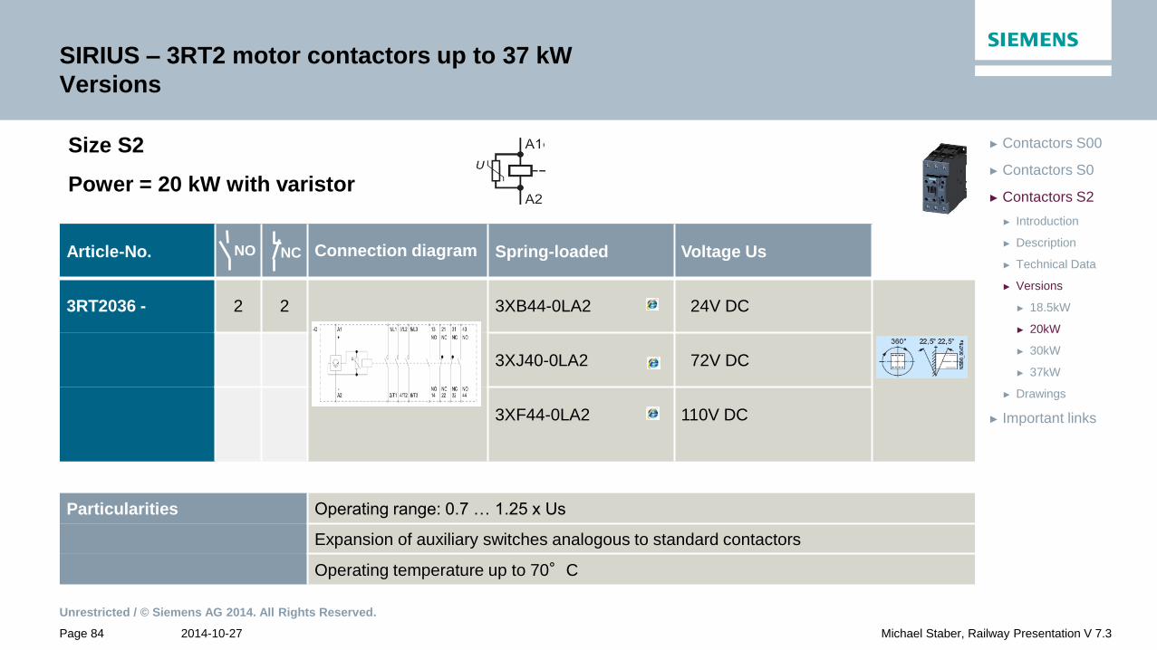
SIRIUS – 3RT2 motor contactors up to 37 kW
Versions
Article-No. Connection diagram Spring-loaded Voltage Us
3RT2036 - 2 2 3XB44-0LA2 24V DC
3XJ40-0LA2 72V DC
3XF44-0LA2
110V DC
Particularities Operating range: 0.7 … 1.25 x Us
Expansion of auxiliary switches analogous to standard contactors
Operating temperature up to 70°C
NO NC
Size S2
Power = 20 kW with varistor

Unrestricted / © Siemens AG 2014. All Rights Reserved.
2014-10-27 Page 85 Michael Staber, Railway Presentation V 7.3
► Important links
► Drawings
► 37kW
► 30kW
► 20kW
► 18.5kW
► Versions
► Technical Data
► Description
► Introduction
► Contactors S2
► Contactors S0
► Contactors S00
SIRIUS – 3RT2 motor contactors up to 37 kW
Versions
Article-No. Connection diagram Screw-type Voltage Us
3RT2037 - 1 1 1XB40-0LA2 24V DC
1XF40-0LA2 110V DC
Particularities Operating range: 0.7 … 1.25 x Us
Expansion of auxiliary switches analogous to standard contactors
Operating temperature up to 70°C
NO NC
Size S2
Power = 30 kW with varistor
Unrestricted / © Siemens AG 2014. All Rights Reserved.
2014-10-27 Page 86 Michael Staber, Railway Presentation V 7.3
► Important links
► Drawings
► 37kW
► 30kW
► 20kW
► 18.5kW
► Versions
► Technical Data
► Description
► Introduction
► Contactors S2
► Contactors S0
► Contactors S00
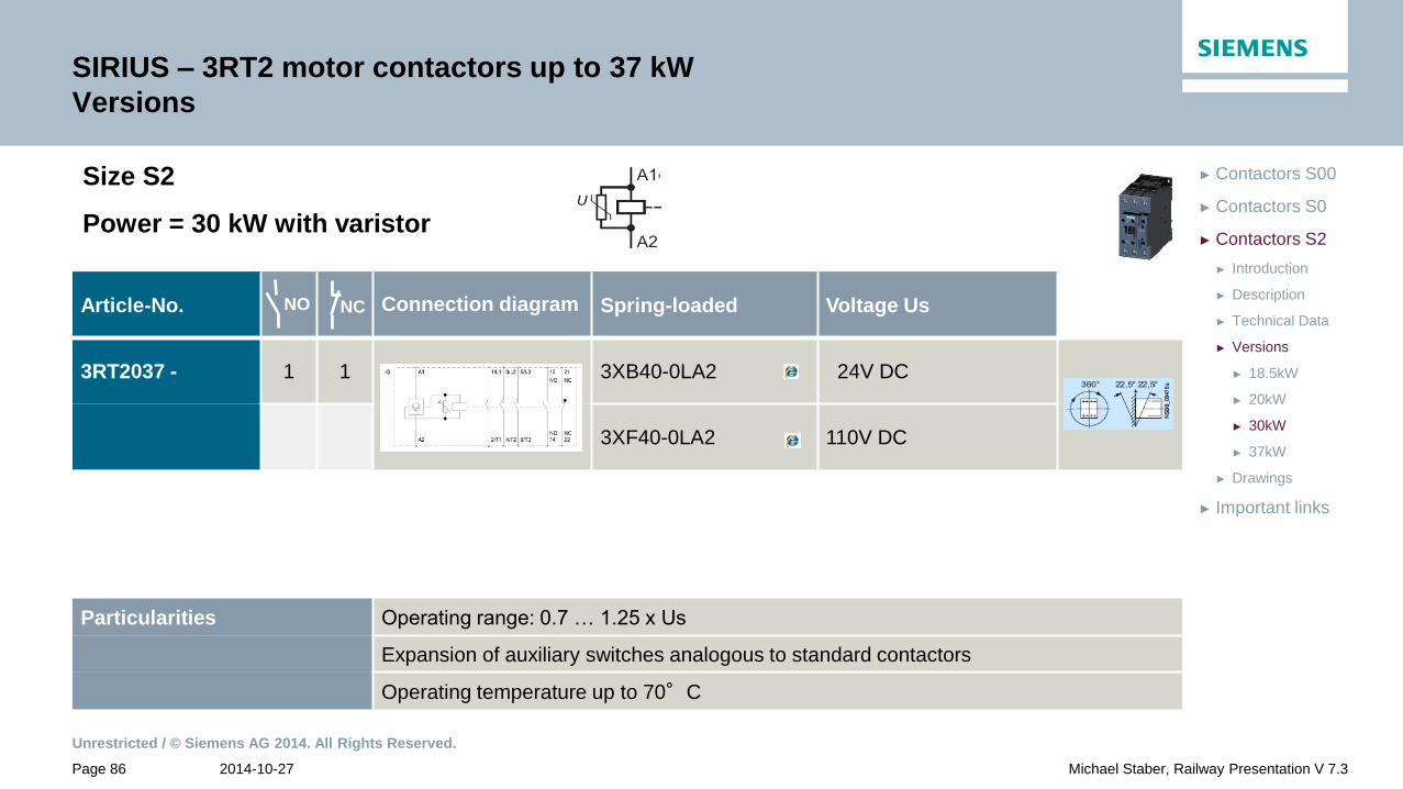
SIRIUS – 3RT2 motor contactors up to 37 kW
Versions
Article-No. Connection diagram Spring-loaded Voltage Us
3RT2037 - 1 1 3XB40-0LA2 24V DC
3XF40-0LA2 110V DC
Particularities Operating range: 0.7 … 1.25 x Us
Expansion of auxiliary switches analogous to standard contactors
Operating temperature up to 70°C
NO NC
Size S2
Power = 30 kW with varistor

Unrestricted / © Siemens AG 2014. All Rights Reserved.
2014-10-27 Page 87 Michael Staber, Railway Presentation V 7.3
► Important links
► Drawings
► 37kW
► 30kW
► 20kW
► 18.5kW
► Versions
► Technical Data
► Description
► Introduction
► Contactors S2
► Contactors S0
► Contactors S00
SIRIUS – 3RT2 motor contactors up to 37 kW
Versions
Article-No. Connection diagram Spring-loaded Voltage Us
3RT2037 - 2 2 3XB44-0LA2 24V DC
3XF44-0LA2 110V DC
Particularities Operating range: 0.7 … 1.25 x Us
Expansion of auxiliary switches analogous to standard contactors
Operating temperature up to 70°C
NO NC
Size S2
Power = 30 kW with varistor

Unrestricted / © Siemens AG 2014. All Rights Reserved.
2014-10-27 Page 88 Michael Staber, Railway Presentation V 7.3
► Important links
► Drawings
► 37kW
► 30kW
► 20kW
► 18.5kW
► Versions
► Technical Data
► Description
► Introduction
► Contactors S2
► Contactors S0
► Contactors S00
SIRIUS – 3RT2 motor contactors up to 37 kW
Versions
Article-No. Connection diagram Screw-type Voltage Us
3RT2038 - 1 1 1XB40-0LA2 24V DC
1XF40-0LA2 110V DC
Particularities Operating range: 0.7 … 1.25 x Us
Expansion of auxiliary switches analogous to standard contactors
Operating temperature up to 70°C
NO NC
Size S2
Power = 37 kW with varistor

Unrestricted / © Siemens AG 2014. All Rights Reserved.
2014-10-27 Page 89 Michael Staber, Railway Presentation V 7.3
► Important links
► Drawings
► 37kW
► 30kW
► 20kW
► 18.5kW
► Versions
► Technical Data
► Description
► Introduction
► Contactors S2
► Contactors S0
► Contactors S00
SIRIUS – 3RT2 motor contactors up to 37 kW
Versions
Article-No. Connection diagram Spring-loaded Voltage Us
3RT2038 - 1 1 3XB40-0LA2 24V DC
3XF40-0LA2 110V DC
Particularities Operating range: 0.7 … 1.25 x Us
Expansion of auxiliary switches analogous to standard contactors
Operating temperature up to 70°C
NO NC
Size S2
Power = 37 kW with varistor

Unrestricted / © Siemens AG 2014. All Rights Reserved.
2014-10-27 Page 90 Michael Staber, Railway Presentation V 7.3
► Important links
► Drawings
► 37kW
► 30kW
► 20kW
► 18.5kW
► Versions
► Technical Data
► Description
► Introduction
► Contactors S2
► Contactors S0
► Contactors S00
SIRIUS – 3RT2 motor contactors up to 37 kW
Versions
Article-No. Connection diagram Spring-loaded Voltage Us
3RT2038 - 2 2 3XB44-0LA2 24V DC
Particularities Operating range: 0.7 … 1.25 x Us
Expansion of auxiliary switches analogous to standard contactors
Operating temperature up to 70°C
NO NC
Size S2
Power = 37 kW with varistor
Unrestricted / © Siemens AG 2014. All Rights Reserved.
2014-10-27 Page 91 Michael Staber, Railway Presentation V 7.3
► Important links
► Drawings
► Versions
► Technical Data
► Description
► Introduction
► Contactors S2
► Contactors S0
► Contactors S00
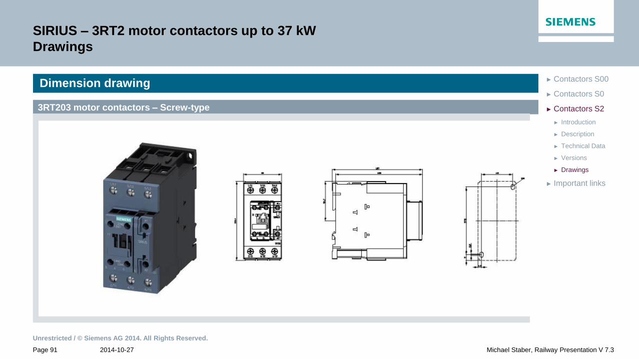
SIRIUS – 3RT2 motor contactors up to 37 kW
Drawings
Dimension drawing
3RT203 motor contactors – Screw-type

Unrestricted / © Siemens AG 2014. All Rights Reserved.
2014-10-27 Page 92 Michael Staber, Railway Presentation V 7.3
► Important links
► Drawings
► Versions
► Technical Data
► Description
► Introduction
► Contactors S2
► Contactors S0
► Contactors S00
SIRIUS – 3RT2 motor contactors up to 37 kW
Drawings
Dimension drawing
3RT203 motor contactors – Spring-loaded

Unrestricted / © Siemens AG 2014. All Rights Reserved.
2014-10-27 Page 93 Michael Staber, Railway Presentation V 7.3
► Important links
► Drawings
► Versions
► Technical Data
► Description
► Introduction
► Contactors S2
► Contactors S0
► Contactors S00
SIRIUS – 3RT2 motor contactors up to 37 kW
Drawings
Dimension drawing
3RT203 motor contactors – Spring-loaded
Unrestricted / © Siemens AG 2014. All Rights Reserved.
2014-10-27 Page 94 Michael Staber, Railway Presentation V 7.3
► Important links
► Contactors S2
► Contactors S0
► Contactors S00
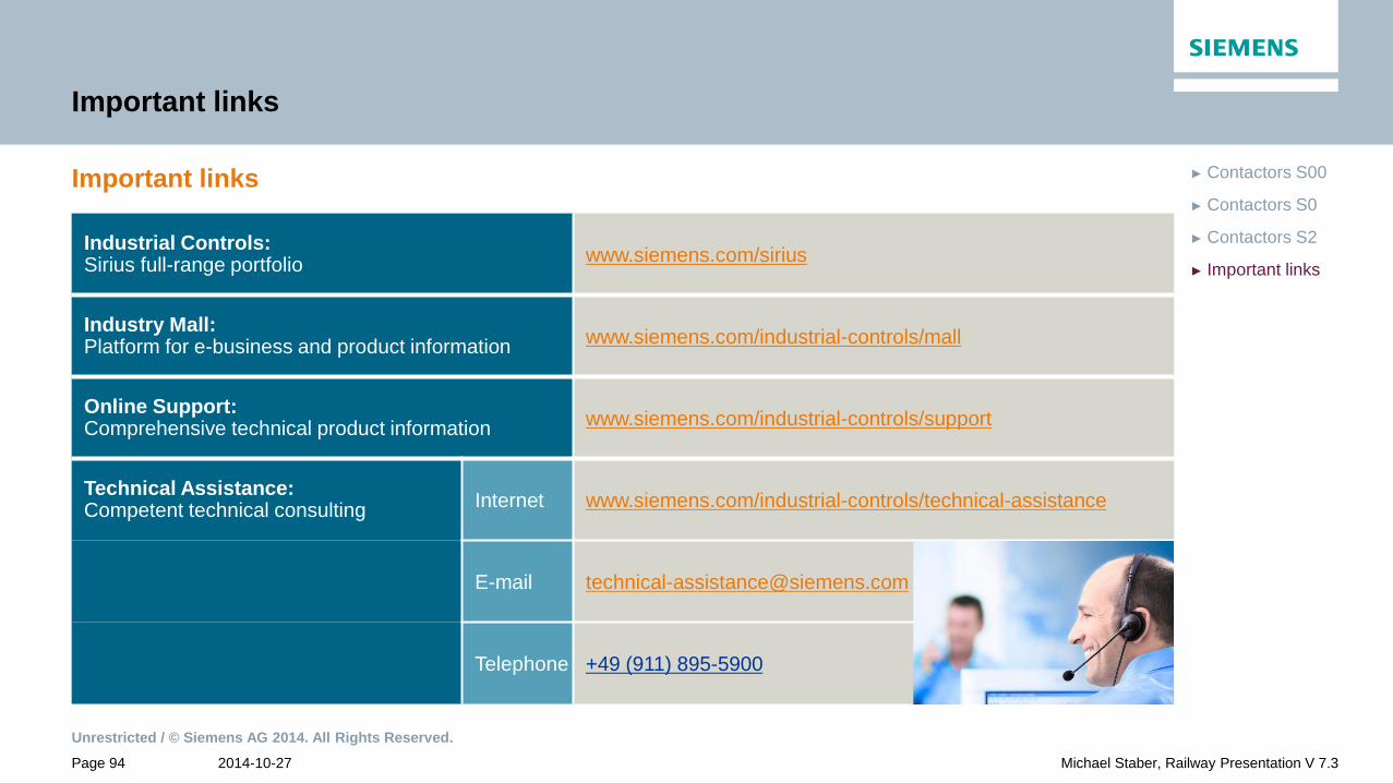
Important links
Important links
Industrial Controls: Sirius full-range portfolio
www.siemens.com/sirius
Industry Mall: Platform for e-business and product information
www.siemens.com/industrial-controls/mall
Online Support: Comprehensive technical product information
www.siemens.com/industrial-controls/support
Technical Assistance: Competent technical consulting
Internet www.siemens.com/industrial-controls/technical-assistance
E-mail [email protected]
Telephone +49 (911) 895-5900
Unrestricted / © Siemens AG 2014. All Rights Reserved.
2014-10-27 Page 95 Michael Staber, Railway Presentation V 7.3
► Important links
► Contactors S2
► Contactors S0
► Contactors S00
Disclaimer
The information provided in this brochure comprises descriptions or performance
characteristics which may not always be applicable in the described form to the
specific application case or which may change due to product advancement.
The desired performance characteristics shall only be binding if they are
expressly specified upon contract conclusion. Subject to availability and technical
changes.
All product designations may be trademarks or product names of Siemens AG or
supplier companies whose utilization by third parties for their own purposes could
violate the rights of the owners.
Unrestricted / © Siemens AG 2014. All Rights Reserved.
2014-10-27 Page 96 Michael Staber, Railway Presentation V 7.3
Staber Michael
Siemens AG
DF CP S&MK V&KAM
Breslauer Strasse 5
90766 Fuerth, Germany
Phone: +49 (911) 750 - 9042
Cellular: +49 (179) 2212179
E-Mail: [email protected]
Thank you for your attention!
www.siemens.com/railway-components