Electrical Bonding: A Survey of Requirements, Methods, and ...
56
Electrical Bonding: A Survey of Requirements, Methods, and Specifications R. W. Evans Computer Sciences Corporation, Huntsville, Alabama Prepared for Marsha11 Space Flight Center under Contract NAS8-60000 and sponsored by the Space Environments and Effects Program managed at the Marshall Space Flight Center - -- March 1998 https://ntrs.nasa.gov/search.jsp?R=19980201283 2018-04-03T02:24:22+00:00Z
Transcript of Electrical Bonding: A Survey of Requirements, Methods, and ...

Electrical Bonding: A Survey of Requirements, Methods, and Specifications R. W. Evans Computer Sciences Corporation, Huntsville, Alabama
Prepared for Marsha11 Space Flight Center under Contract NAS8-60000 and sponsored by the Space Environments and Effects Program managed at the Marshall Space Flight Center
- --
March 1998
https://ntrs.nasa.gov/search.jsp?R=19980201283 2018-04-03T02:24:22+00:00Z

The NASA ST1 Program Office.. .in Profile
Since its founding, NASA has been dedicated to the advancement of aeronautics and space science. The NASA Scientific and Technical Information (STI) Program Office plays a key part in helping NASA maintain this important role.
The NASA ST1 Program Office is operated by Langley Research Center, the lead center for NASA's scientific and technical information. The NASA ST1 Program Office provides access to the NASA ST1 Database, the largest collection of aeronautical and space science ST1 in the world. The Program Office is also NASA's institutional mechanism for disseminating the results of its research and development activities. These results are published by NASA in the NASA ST1 Report Series, which includes the following report types:
TECHNICAL PUBLICATION. Reports of completed research or a major significant phase of research that present the results of NASA programs and include extensive data or theoretical analysis. Includes compilations of significant scientific and technical data and information deemed to be of continuing reference value. NASA's counterpart of peer-reviewed formal professional papers but has less stringent limitations on manuscript length and extent of graphic presentations.
TECHNICAL MEMORANDUM. Scientific and technical findings that are preliminary or of specialized interest, e.g., quick release reports, working papers, and bibliographies that contain minimal annotation. Does not contain extensive analysis.
CONTRACTOR REPORT. Scientific and technical findings by NASA-sponsored contractors and grantees.
CONFERENCE PUBLICATION. Collected papers from scientific and technical conferences, symposia, seminars, or other meetings sponsored or cosponsored by NASA.
SPECIAL PUBLICATION. Scientific, technical, or historical information from NASA programs, projects, and mission, often concerned with subjects having substantial public interest.
TECHNICAL TRANSLATION. English-language translations of foreign scientific and technical material pertinent to NASA's mission.
Specialized services that complement the ST1 Program Office's diverse offerings include creating custom thesauri, building customized databases, organizing and publishing research results.. .even providing videos.
For more information about the NASA ST1 Program Office, see the following:
* Access the NASA ST1 Program Home Page at http://www.sti. nasa.gov
* E-mail your question via the Internet to [email protected]
* Fax your question to the NASA Access Help Desk at (301) 621-0134
Telephone the NASA Access Help Desk at (301) 621-0390
Write to: NASA Access Help Desk NASA Center for Aerospace Information 800 Elluidge Landing Road Linthicum Heights, MD 2 1090-2934

Electrical Bonding: A Survey of Requirements, Methods, and Specifications R. W. Evans Computer Sciences Corporation, Huntsville, Alabama
Prepared for Marshall Space Flight Center under Contract NAS8-60000 and sponsored by the Space Environments and Effects Program managed at the Marshall Space Flight Center
National Aeronautics and Space Administration
Marshall Space Flight Center MSFC, Alabama 35812
March 1998

Available from:
NASA Center for Aerospace Information 800 Elkridge Landing Road Linthicum Heights, MD 2 1090-2934 (301) 621-0390
National Technical Information Service 5285 Port Royal Road Springfield, VA 22 161
(703) 4874650

Preface
There are several reasons for requiring good electrical
conductivity between equipment and structure and between
various parts of structure. Improved electrical bonding with
reduced effort can result from understanding the different
types of bonding requirements and the reasons for each.
Good electrical bonding on a spacecraft is often not
completely verifiable. In some cases electrical bonding
specifications state requirements that are compromises so
they can be verified by measurement. These compromised
requirements are often met by methods that may not provide a
good bond under certain circumstances.
This document attempts to explain the various types of
electrical bonding requirements and to provide the basic
requirement for each type where possible. In some cases the
specific values of bonding resistance and impedance may vary depending upon other requirements on the program. In these
cases the type of data required to determine the specific
values is defined.


TABLE OF CONTENTS
Preface
Acronyms and Abbreviations
1.0 Introduction
2.0 Specifications
3.0 Requirements and Purpose
3.1 Power Current Return Path
3.2 Shock and Fault Protection
3.3 Electromagnetic Interference (RF)
3.4 Antenna Ground Plane
3.5 Lightning Protection
3.6 Electrostatic Discharge
4.0 Bonding Methods
4.1 Surface Cleaning and Finishing
4.2 Galvanic Corrosion
4.3 Straps Where Unavoidable
4.4 Impedance and Resistance
4.5 Tubing
4.6 Composite Material Enhancement
4.7 Limitations on Some Materials in Space
5.0 Verification
TABLES
Table 1, Summary of Electrical Bonding Requirements 3
Table 2, Galvanic Series 21
APPENDICES
Appendix A, List of Specifications and Processes


ACRONYMS AND ABBREVIATIONS
A
'A"
EED
EMC
ESD
GFRP
'H"
ISS
k
kHz
kV
MHz
area, square inches
class of bond relating to antennas
alternating current
capacitance, farads
class of bond relating to current return
centimeters
distance between box and structure, inches
diameter of jumper, inches
decibels
direct current
electromagnetic environmental effects
initial charged voltage
final 'safe" voltage
electro-explosive device
electromagnetic compatibility
electromagnetic interference
electrostatic discharge
frequency, hertz
resonant frequency
graphite filament reinforced plastic
class of bond relating to fault current hazard
current through short circuit
International Space Station
dielectric constant
kilohertz
kilovolts
inductance, henries or microhenries
length, inches
class of bond relating to lightning
natural logarithm
megahertz
milliamps
millijoules

NASA
PF psi
Q R
\\ R 11
R,
R s
T
R w
RF
" s "
National Aeronautics and Space Administration
picofarads
pounds per square inch
ratio of reactance to resistance
resistance, ohms
class of bond related to radio frequencies
resistance of return path through structure
power source resistance
total resistance in shorted circuit
wire resistance from source to shorting point
radio frequency
class of bond related to electrostatic charge
time or time constant, seconds
thickness of strap, inches
joules
volts
source voltage
width of strap, inches
reactance, ohms
capacitive reactance
inductive reactance
impedance, ohms
wavelength
microhenry
v i i i

ELECTRICAL BONDINa, A SURVEY OF REQUIREMENTS,
WETHODS, AND SPECIFICATIONS
1.0 INTRODUCTION
This document is the result of a review of major electrical
bonding specifications and some of the processes used in the
United States. Its intent is to provide information helpful to
engineers imposing bonding requirements on various programs,
reviewing waiver requests, or modifying specifications.
This document discusses the specifications, the types of
bonds, the intent of each, and the basic requirement where
possible. Additional topics discussed are resistance versus
impedance, bond straps, corrosion, finishes, and special
applications.
2.0 SPECIFICATIONS
MIL-B-5087B, M i l i t a r y S p e c i f i c a t i o n , Bonding, E l e c t r i c a l , and
L igh tn ing Pro t ec t i on , f o r Aerospace Systems, has been the standard
for electrical bonding for space vehicles for many years. It has
recently been superseded by MIL-STD-464, Department O f Defense
I n t e r f a c e Standard, Electromagnetic Environmental E f f e c t s ,
Requirements f o r Systems. MIL-B-5087B classifies bonds according
to the purpose of the bond and sets specific resistance or
impedance requirements according to the class. MIL-STD-464
changes this policy and sets more general requirements based on
the purpose of the bond to allow the equipment developer more
leeway to explore new or unique methods of electrical bonding.
SSP-3 0245, Space S t a t i o n E l e c t r i c a l Bonding Requirements , is a
modification of MIL-B-5087B for the International Space Station.
It reduces the number of applicable bonding classes and adds a few
other requirements. MIL-STD-13 10G, Department o f Defense,

Standard Practice for Shipboard Bonding, Grounding, and Other
Techniques for Electromagnetic Compatibility and Safety, is
applicable for shipboard bonding. It uses a classification system
based on whether the bond is permanent, semipermanent, or uses a
bond strap.
Table 1 presents an outline of the MIL-B-5087B bonding
classes and the major electrical bonding requirements.

Table 1. - Summary of MIL-BS087B Electrical Bonding Requirements
CLASS "R" Radio Frequency
CLASS "A" Antenna Ground
Plane
CLASS "La Lightning
CLASS "C' Power Return
CLASS "S" Electrostatic
Discharge
CLASS "H" Shock Hazard
LOW CURRENT Protects against electrostatic discharge. Applies lto any item subject to electrostatic charging.
Allows moderate impedance. Jumpers and straps acceptable.
I
HIGHCURRENT Applies to equipment or structure that would carry current resulting from a lightning strike.
High current requires low impedance at moderate frequency. Straps and jumpers must withstand high magnetic forces.
H W FRKXlENCY LOWFRKXlENCY
Applies to structure near certain types of antennas. Limited to specific frequencies.
Allows moderate impedance at high frequencies. Short, wide strap may be acceptable.
HIGH Protects against shock to personnel. Applies to equipment & structure that may be required to carry fault current in case of a short to case or structure.
Requires low impedance & low voltage across joints to prevent shock hazard due to short. Jumpers and straps acceptable.
LONCURRENT Applies to equipment that could generate, retransmit, or be susceptible to RF. Covers wide frequency range.
Low current allows moderate RF impedance at high frequency. Direct contact preferred. No jumpers. Short, wide strap may be used as last resort.
CURRENT Reduces power and voltage losses. Applies to equipment & structure when required to carry intentional power current through structure.
Requires low impedance & low voltage across joints to assure adequate power to the user. Jumpers and straps acceptable.

3.0 REQUIREMENTS AND PURPOSE
This section discusses the various classes of bonding
requirements from MIL-B-5087B and provides similar requirements
from other specifications. A commentary will discuss the reasons
for the requirements and possible modifications.
3 . 1 P o w e r C u r r e n t R e t u r n P a t h
MIL-B-5087B class 'C" limits the total impedance of wires,
cables, and ground return paths so that the voltage drop for power
returned through structure is limited to 1 volt for a 28 volt
system and 4 volts for a 115 volt system. It also requires
special fault current bonding at joints where explosive fuel or
gas may be present to prevent ignition due to heating or arcing
from fault current flow. A curve limits resistance levels at each
bond connection based on the maximum fault current possible.
These levels are approximately 0.74 milliohrns at 100 amps of fault
current and 0.074 milliohms at 1000 amps
MIL-STD-464 states, "For systems using structure for power
return currents, bonding provisions shall be provided for current
return paths for the electrical power sources such that the total
voltage drops between the point of regulation for the power system
and the electrical loads are within the tolerances of the
applicable power quality standard."
Common tary
Actual dc resistance values required for electrical bonds
from equipment to structure and from structure to structure will
depend upon the power system for the particular project and
probably upon the location of the bond joint within the vehicle.
Each project should require certain voltage to be delivered across
the loads. The bonding requirement will then depend upon the
source voltage and the maximum current draw.
Several examples of bonding methods using bonding jumpers are
presented in MIL-B-5087B. Since these methods cover several

pages, they catch the attention of the first time user who
immediately thinks good bonding requires a jumper. These examples
are applicable only for class "Cn bonds which provide current
paths for power that is intentionally returned through structure.
NASA space vehicles very rarely use this return-through-structure
method, so class 'CU is not usually applicable.
3.2 Shock and Fault Protection
MIL-B-5087B class 'HU requires less than 0.1 ohm resistance
for metallic conduit at each termination and break point. It also
requires resistance from exposed frames or parts of electrical or
electronic equipment to structure to be less than 0.1 ohms.
MIL-STD-464 states, "Bonding of all exposed electrically
conductive items subject to fault condition potentials shall be
provided to control shock hazard voltages and allow proper
operation of circuit protection devices."
MIL-STD-1310G requires less than 0.1 ohms dc and less than 25
ohms at 30 MHz for all electrical equipment to structure.
Commentary
Circuit protection devices limit current to levels that will
not cause a significant temperature increase in the circuit
wiring. The fault current resulting from a short between a power
wire and a metallic equipment case or other metallic structure
must be high enough to trip circuit protection devices in a timely
manner.
The total resistance (R,) in a typical shorted circuit can be
found by :
Where,
R, = power source resistance
R, = wire resistance from source to shorting point

R, = resistance of return path through structure
The shorted current (I,) value is found by:
Where,
Vs = source voltage
Typically this current is considerably higher than the fuse
or breaker value, and it trips the device quickly. However, a
circuit breaker can sometimes take several seconds to trip with a
current twice its rating. The fault current path usually consists
of metallic structure with several joints in series. A poorly
bonded joint, or a large number of joints, adds significantly to
the total ground path resistance. This resistance may allow the
shorting current enough time to become a fire hazard. It may even
limit the current to less than the circuit breaker rating. The
resulting voltage developed on the exposed chassis where the short
occurs can be a shock hazard.
MIL-HDBK-274, Mili tary Handbook, Electrical Grounding for
Aircraft Safety, states for personnel safety the fault current
return path should be able to allow up to 5 times the breaker
rated current with a trip time of 0.2 seconds. Using this
guideline a 120 volt, 50 amp service would require a total fault
current return path resistance of 0.5 ohms or less.
MIL-HDBK-274 suggests protection from shock hazard from
voltages above 30 volts, but fire hazards may occur with much
lower voltages. SAE ARP 1870, Aerospace Systems Electrical
Bonding and Grounding for Electromagnetic Compatibility and
Safety, restricts voltages on electronic equipment cases to less
than 4.5 volts and requires no fire or damage to the bond in the
event of short to case.
When fault current must flow through partially conductive

structure such as graphite-epoxy, the current will be limited by
the high resistance of the material as well as the joints, and the
breaker may not trip. This results in a fire or shock hazard.
In an explosive atmosphere or areas where flammable vapors
may occur, extra precaution must be used to ensure no arcs or hot
spots can occur. A primary fault current return path should be
provided around the hazardous area to limit the amount of fault
current possible through joints in the hazardous area. In this
case, the hazardous area fault current requirement of MIL-B-5087B
class 'C" may be applicable to NASA programs.
3.3 Electromagnetic Interference or Radio Frequency (RF)
MIL-B-5087B class 'R" states, 'All electrical and electronic
units or components which produce electromagnetic energy shall be
installed to provide a continuous low impedance path from the
equipment enclosure to the structure. The contractor shall
demonstrate by test that his proposed bonding method results in a
direct current resistance of less than 2.5 milliohms from
enclosure to structure. The bond from the equipment enclosure to
the mounting plate furnished with the equipment shall comply also
with these requirements, except that suitable jumpers may be used
across any necessary vibration isolators."
It also states, "Vehicle skin shall be so designed that a
uniform low-impedance skin is produced through inherent RF bonding
during construction. RF bonding must be accomplished between all
structural components comprising the vehicle. Hatches, access
doors, etc., not in the proximity of interference sources or
wiring, shall be either bonded to or permanently insulated from
vehicle skin, except for the protective static bond."
MIL-STD-464 states, "The system electrical bonding shall
provide electrical continuity across external mechanical
interfaces on electrical and electronic equipment, both within the
equipment and between the equipment and system structure, for
control of E~ such that the system operational performance
requirements are met. For Navy aircraft and Army aircraft

applications, the EM1 bonds shall have a dc resistance of 2.5
milliohms or less across each joint between the subsystem or
equipment enclosure and the system ground reference."
MIL-STD-1310G requires less than 25 ohms at 30 MHz for all
electronic equipment to structure.
SSP-30245 requires less than 100 milliohms at 1 MHz, but it
does not include the impedance of straps where they are used.
Commentary
The Army and Navy retained the historical 2.5 milliohm
requirement just because it was historical, and it worked. Other
users settled for the general requirement for all systems to
implement bonding measures adequate to ensure electromagnetic
compatibility. Responsibility for specific resistance or
impedance levels was left to the developing activity.
In reality there is no basis for 2.5 milliohm requirement
except to ensure a good metal-to-metal contact that can be
expected to be consistent. This value can be met even when mating
two aluminum surfaces that have had a chemical conversion coating
such as Iridite 14-2 to prevent corrosion. The basic requirement
is to have a low impedance at the frequency or frequencies of
interest. The value of this impedance, which is not defined,
depends upon the situation. Acceptable low impedance may be in
the ohms range for RF even though the dc resistance is less than
2.5 milliohms. The resistance is overshadowed by the inductive
reactance of the configuration. Any electronic equipment with
mounting feet will probably have an inductive reactance greater
than 2.5 milliohms at frequencies above 10 MHz. RF bonds may be
satisfactory at several ohms of impedance; but, when straps are
used, even these levels will be quickly exceeded as frequency
increases.
The class "R" bond is not really required on all equipment,
but it is difficult to determine in advance which equipment really
needs to be well bonded. The low impedance to structure is
necessary for certain power line to equipment filters and for
proper operation of overall cable shields terminated to equipment

chassis. Isolated structural elements greater than can pick up
RF from high power transmitters and develop enough voltage to
produce a glow discharge or arcing to other elements.
The 2.5 milliohm dc resistance requirement is probably good
for a standard, but extra effort should not be made just to
satisfy the dc requirement if the RF impedance is much higher due
to the inductance of the configuration. Look at the whole
configuration to get the lowest impedance possible at the
frequencies of interest to produce a good RF bond.
3.4 Antenna Ground Plane
MIL-B-5087B class 'A" requires radiating elements to be
installed and provided with a homogeneous counterpoise or ground
plane of negligible impedance within the operating frequency
ranges of the equipment involved. The ground plane shall be of
adequate dimensions so as not to detract from the desired antenna
radiation patterns. Antennas so designed that efficient operation
depends on low resistance shall have the bond installed so that RF
currents flowing on the external surface of a vehicle will have a
low impedance path of minimum length to the appropriate metal
portion of the antenna.
MIL-STD-464 states, "Antennas shall be bonded to obtain
required antenna patterns and meet the performance requirements
for the antenna."
Cornmen t ary
Some types of antennas require a conductive counterpoise or
ground plane for proper operation. The conductivity value and the
area required should be specified by the antenna developer. This
may or may not affect the bonding requirements on structure near
the antenna. For proper operation of a 1/4 wavelength rod
antenna, for example, the ground plane may need to be highly
conductive up to 1/2 wavelength from the antenna. The ground
plane up to several wavelengths from the antenna may affect the

antenna pattern to a lesser extent. It does not have to be a
perfect conductor, but it should be stable and consistent.
3.5 Lightning Protection
MIL-B-5087B class 'L" specifies that voltages developed
across joints as a result of lightning shall not exceed 500 volts.
It also specifies a lightning current waveform of 200 kiloamps.
It is generally accepted that bonding impedance in the current
path should be less than 2.5 milliohms at each joint to prevent
voltages over 500 volts.
MIL-STD-464 requires the system to meet its operational
performance requirements for both direct and indirect effects of
lightning. It provides sample lightning current waveforms for
design inputs, but it does not specify any specific electrical
bonding requirements for lightning protection.
Cornmen t ary
Electrical bonding in itself does not ensure lightning
protection, but it is a major part of the overall plan. Lightning
current usually enters one extremity of the vehicle and exits at
another extremity. Lightning current is high and voltages
developed across joints are high enough to arc and provide a path
to the exit point. Electrical bonding helps provide the proper
direction for the path. Even when a large current path is
provided to carry the current, attach points across joints still
may be a problem. Arcing at joints can be expected even with good
2.5 milliohm dc bonds. The arc produces an ionized path that
helps carry the current. Through good electrical bonding of the
vehicle skin the majority of the current can be kept on the
outside of the vehicle.
Joints and apertures in the skin allow some voltage to be
induced into underlying cables. This voltage must be kept low
enough to prevent disrupting electronic equipment. Apertures
should be kept as small as possible, and joints should be bonded
in several places so there will not be a long slot between bonds.

Special care must be taken to route current around fuel or
pyrotechnics to prevent arcs that can ignite fuel or current that
can fire pyrotechnics. Fuel and pyrotechnics should be completely
enclosed by conductive material grounded to structure. Wires to
pyrotechnics should be shielded and the shields should have 360"
terminations to the metal enclosure.
3.6 Electrostatic Discharge
MIL-B-5087B, Amendment 2, class 'S" states, 'All isolated
conducting items (except antennas) having any linear dimension
greater than 3 inches, which are external or internal to the
vehicle, carry fluids in motion, or otherwise are subject to
frictional charging, shall have a mechanically secure connection
to the vehicle structure. The resistance of the connection shall
be less than 1 ohm when dry."
" ~ 1 1 metallic pipes, tubes, and hoses that carry petroleum
products or other fluids shall have a mechanically secure
connection to the structure that will measure 1 ohm or less. The
pipe, tube, or hose installation shall be so designed that it will
not be a path for primary electrical power under normal or fault
conditions. Nonmetallic plumbing installations shall be so
designed that the static voltage generated by fluid flow will not
exceed 350 volts at any point outside the pipes, tubes, or hoses."
Amendment 3 deletes the two paragraphs above and sets
requirements for Air Force aircraft fuel systems only.
Electrically powered equipment in the fuel system is required to
meet the class ' C " , hazardous area, requirements. Small
nonelectrical components capable of delivering more than 0.25
millijoules through a static discharge must be bonded with 10
megohms or less resistance to ground, and other fuel system
components shall have an electromechanically secure connection to
structure that measures one ohm or less. MIL-HDBK-274 states that
0.25 millijoules is the energy level required for an arc to ignite
fuel vapor.
SSP 30245 states that all parts with greater than 100 square

centimeters surface area and subject to charging shall not exceed
100 ohms to structure.
MIL-STD-464 requires the system to control and dissipate the
build-up of electrostatic charges caused by precipitation static
effects, fluid flow, air flow, space and launch vehicle charging,
and other charge generating mechanisms to avoid fuel ignition and
ordnance hazards, to protect personnel from shock hazards, and to
prevent performance degradation or damage to electronics. It specifically requires external grounding provisions to prevent
shock to personnel and ignition of fuel or ordinance. Grounding jacks shall be provided at fuel inlets and at convenient points
for servicing and maintenance. The resistance from grounding jack
to system ground shall not exceed one ohm.
Commentary
The resistance to ground affects the rate of discharge for an
item being charged. A low resistance reduces the charge faster,
but bonds with resistances that would be considered high, such as
10 kilohms recommended by MIL-HDBK-274, usually function
adequately. The charging current, usually in microamps, through
the resistance to ground determines the voltage developed. A
requirement for one ohm or less to ground is a good requirement
for metal items because any good connection will measure less than
one ohm. Under some circumstances, such as when semiconductive
materials or complex configurations are used, this limit may be
increased up to ten kilohms or even more in many cases. The
contact must be secure and not intermittent. Metal straps or
jumpers across joints are adequate since the current is dc.
Charging mechanisms include separation of unlike materials,
charges induced from other charged items, triboelectric charging,
etc. Separation of materials includes movement or removal of
certain types of clothing, peeling off tape, removing dust covers,
fluid flow, etc. Induction comes from an isolated item being near
a second item that is being charged. If the second item is
suddenly discharged the isolated item retains the charge until it
drains off depending on its resistance to ground. An example is a

charged cloud causing an opposite charge to develop on a nearly
isolated item on earth. If lightning discharges the cloud to
ground, the earth in the area discharges quickly, but the nearly
isolated item retains a charge until it can drain off through the
high resistance to the earth. Triboelectric charging occurs when
a vehicle hits or is hit by particles such as dust or snow. The
charging current is very low, usually less than 30 microamps for
wind blown dust hitting a parked airplane.
An arc discharge can cause direct effects to the item being
discharged and to the item receiving the discharge. Indirect
effects may be caused by voltages induced into neighboring items.
Direct or indirect effects include physical damage to an item,
upset of operation, ignition, or shock to personnel. The
likelihood of damage or upset depends upon the threshold level.
Some typical damage threshold levels are taken from MIL-HDBK-
274 and presented here.
Reflex action shock 10 mJ, 50 V
Severe shock (dc) 1.35 mJ, 45 V, 3 rnA
EED ignition 35 mJ
Component damage 35 mJ
Component upset 10 mJ
Fuel vapor ignition 0.25 mJ
The amount of energy stored in a charged item may be found
by:
Where,
u = energy stored (joules)
C = capacitance to ground (farads)
V = charge voltage

The voltage is limited to the breakdown voltage between the
charged item and ground. The maximum voltage before breakdown in
air is approximately 30 kV/cm or 75 kV/inch; but, typically, it is
about 8 kV/cm or 20 kV/inch due to rough surfaces, corners, etc.
The capacitance between two conductive plates such as from
equipment to structure is found by:'
Where,
k = dielectric constant (= 1 for air),
A = area of mating surfaces (square inches)
d = distance between the box and the structure (inches)
Capacitance values for aircraft are consistently measured at
0.002 to 0.005 microfarads with 40 megohms resistance to ground
through the tires.
Conductive items capable of being charged must be
electrically bonded to structure if their surface is greater than
100 square centimeters according to SSP 30245, and if their length
is greater than 3 inches according to MIL-B-5087B. An example of
the energy transfer possible from an item in this size range can
be calculated. Assume a 10 square inch mating surface setting 0.1
inch above the ground plane.
The capacitance to ground is:
C = 0.224 (E) picofarads 0.1
The maximum field strength before discharge is 75 kV/inch;
and, for a separation distance of 0.1 inch, the maximum voltage
that can be developed is 7.5 kV.
F. E. Terman, Radio Engineers' Handbook, McGraw-Hill Co., New York, 1943.
14
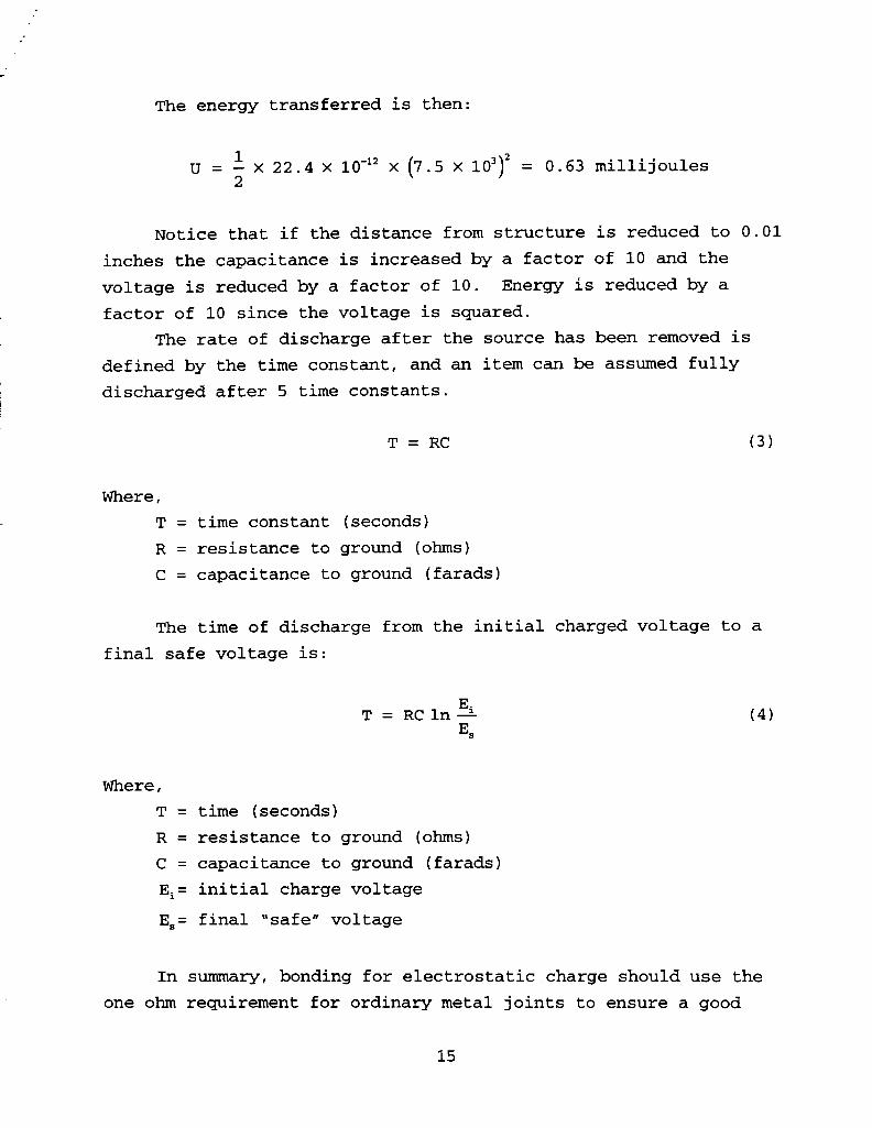
The energy transferred is then:
1 U = - x 22 .4 x 10'" x (7.5 x 10')~ = 0.63 millijoules
2
Notice that if the distance from structure is reduced to 0.01
inches the capacitance is increased by a factor of 10 and the
voltage is reduced by a factor of 10. Energy is reduced by a
factor of 10 since the voltage is squared.
The rate of discharge after the source has been removed is
defined by the time constant, and an item can be assumed fully
discharged after 5 time constants.
Where,
T = time constant (seconds)
R = resistance to ground (ohms)
C = capacitance to ground (farads)
The time of discharge from the initial charged voltage to a
final safe voltage is:
Where,
T = time (seconds)
R = resistance to ground (ohms)
C = capacitance to ground (farads)
Ei= initial charge voltage
E,= final 'safe" voltage
In summary, bonding for electrostatic charge should use the
one ohm requirement for ordinary metal joints to ensure a good

connection. Good connections that measure up to 10 kilohms for
unusual configurations or semiconductive materials should also be
acceptable. Jumpers and straps may be used.
In borderline cases determine whether an item requires
bonding for electrostatic discharge by calculating the amount of
energy that can be stored on the item and compare it to damage levels for the item and for any item that may receive the
discharge.

4 . 0 BONDING METHODS
Equipment and structure with metal-to-metal joints that are
joined by processes that transform the mated surfaces into one
piece of metal such as by welding or brazing are considered
permanent and inherently bonded. Semipermanent joints are held
together by screws, rivets, clamps, etc. To provide a good
electrical bond the semipermanent mating surfaces should be
cleaned of all insulating material before connection. A good dc
connection will measure less than the 2.5 milliohm limit for class
"R" bonds. Bond straps or jumpers may be adequate for some types
of bonds, but it should be recognized that they will present a
high impedance at high frequencies. Special requirements may be
necessary for tubing, composite materials, metalized thermal
blankets, etc.
4.1 Surface Cleaning and Finishing
Various bonding specifications refer to MIL-C-5541, Military
Specification, Chemical Conversion Coatings on Aluminum and
Aluminum Alloys, for protective chemical conversion coatings for
aluminum and aluminum alloys. This specification provides for
class IA coatings for maximum protection and class 3 where
electrical conductivity is required. Class 3 may use a different
material, or it may be a thinner coating using the same material
as for class IA. The coating materials are required to meet MIL-
C-81706, Chemical Conversion Materials for Coating Aluminum and
Aluminum Alloys, and are supposed to be preapproved and accepted
for listing on the Qualified Products List, QPL-81706. Commonly
used examples of these materials are Iridite 14-2, Alodine 600,
and Alodine 1200. MIL-C-5541 describes cleaning procedures for
aluminum surfaces, and it states the chemical coatings may be
applied by spray, brush, or immersion after all welding and
mechanical operations have been completed. The more conductive
class 3 coating uses a short immersion time or is brushed on to
form a thinner coating.
17

The hard, nonconductive aluminum oxide coating is removed
during the cleaning process, and chromate coatings are applied to
bare aluminum. The thickness of the coating depends upon the
amount of time the metal is immersed, up to a point. After five
minutes or so in the bath little thickness is added. Typical
coatings may range from 10 to 1000 nanometers and may vary in
color from clear to light yellow to dark brown depending upon the
thickness. The thinner coatings are used as a paint base and for
protection where good electrical conductivity is required.
Thicker coatings may be wed alone for protection. The thinner
coating is most conductive, however the thicker coating is still
more conductive than the aluminum oxide on the original material.
To meet the usual 2.5 milliohm resistance limit a thin coating is
required. However even the thicker coatings usually measure less
than 10 milliohms.
As with many military specifications, this one is designed to
be used for multiple units, and provisions for testing and
inspection apply to each lot. Test specimens are to be coated and
submitted to a 168 hour salt spray test, rinsed, and checked for
compliance with spot and pit requirements. A paint adhesion test
is prescribed for equipment to be painted after coating. An
electrical conductivity test for class 3 coatings requires mating
samples at 200 psi and measuring dc resistance across the joint.
The limit is 5000 microhms per square inch immediately after
joining and 10000 microhms per square inch after the 168 hour salt
spray. Unless precautions are taken, chromate coatings are easily
penetrated during the mechanical mating of two surfaces; and
resistance measurements taken before the exposed aluminum oxidizes
may be lower than later measurements.
protective coatings for magnesium are described in MIL-M-
3 171C, ~agnesium Alloys, Processes for Pretreatment and Prevention
of Corrosion. Several types of coatings are described, but MIL-B-
5087B recommends Type 1, chrome pickle, be used. This process
uses a weak chromic acid solution to clean down to bare metal.
The coating process uses sodium dichromate and nitric acid that
etches some of the surface away and deposits a chromate coating.

No resistance requirements or methods of verification are given.
Resistance measurements of typical mating surfaces may be
used to verify the mating process using chromate coating provides
a satisfactory bond. Then all bonds using that process can be
verified by similarity. When equipment is mounted in orbit, the
new equipment can be protected until ready for mating, but the
footprint may be exposed to the space environment for months or
years in the case of the International Space Station (ISS). The
ISS bonding specification recommends plating these mating surfaces
with nickel. Boeing document, D683-29033-1, Process Specification
for Electrical Bonding and Grounding, does not allow chemical
conversion coatings in habitable spacecraft due to corrosion
potential. However, this author has not found evidence that
chromate conversion coatings on aluminum will be particularly
susceptible to corrosion in the space environment. It appears
that if a problem occurs, it will be from contamination settling
on the footprint or from debris pitting external surfaces. These
can occur whether the surfaces are nickel plated or finished with
chromate coating.
4.2 Galvanic Corrosion
Where dissimilar metals are placed in contact, galvanic
reaction may cause corrosion of the metal that is higher in the
galvanic series. MIL-B-5087B warns that if the condition cannot
be avoided the most active of the metals should be replaceable.
MIL-STD-889, Dissimilar Metals, contains considerably more good
information on the subject. The galvanic series gives a voltage
level for each material while immersed in an electrolyte solution.
The voltages may differ with the electrolyte and even the order of
the material in the series may change. For most aerospace work
the table using sea water as an electrolyte is used. Table 2 is
an example. To protect against corrosion the two metals in
contact should be close together in the series. The area of the
most anodic metal, higher in the series, should be larger than the
cathodic metal. The larger the anodic area the lower the current

density on the anode. Select small parts such as bolts and nuts
of material compatible with the cathode. (This conflicts somewhat
with the MIL-B-5087B warning to make the more active of the metals
replaceable.) All edges should be sealed from moisture.

Table 2 - Galvanic 8erieea More Active (Anodic) Group I magnesium Group I1 zinc
aluminum aluminum alloy 7072 aluminum alloy 7079-T6 cadmium aluminum alloy 6061-T6 aluminum alloy 2024-T4
Group I11 tin stainless steel 430 (active) lead steel 1010 cast iron
Group IV nickel chromium stainless steel 430 (passive) brass
Group V copper Monel 400 titanium silver gold graphite
Less Active (Cathodic)
Metals toward the top of the series are more active and
will corrode when placed in contact with a metal lower in the
series in a seawater electrolyte environment.
Generally, metals in the same group may be placed in
contact with each other. -
Metals from separate groups must be protected from
corrosion by coating and by sealing the edges to preclude
moisture . Avoid leaving a small unprotected anodic area compared to
the cathodic area in contact with the electrolyte. The smaller
the area the greater the current density and the greater the
corrosion.
An intermediate metal should be placed between two metals
that are far apart in the series to reduce the tendency to
corrode. The intermediate metal can be a plating.
Data taken from MIL-STD-8898 and AFSC DH 1-4.

4 - 3 Straps Where Unavoidable
MIL-B-5087B gives details of how to use bonding jumpers
primarily for current return paths (class 'C" bonds). It allows
short jumpers across vibration mounts for class "Rn and states
that they should be as short as possible.
MIL-STD-1310G defines four types of bond straps -- corrosion
resistant steel with lugs, corrosion resistant steel with holes,
flat solid copper, and flat copper braid.
STP 65115, Engineering Process Specification, Electrical and
Electronic Bonding Connections (Lockheed-Martin) , describes use of jumpers and aluminum foil primarily for lightning bonds.
Some procedures limit bond strap length to width ratios to 3
to 1 or 5 to 1. The impedance of these straps exceeds 2.5
milliohms at approximately 20 kHz. It is at least 100 milliohms
at 1 MHz and 1 ohm at 10 MHz. Straps may be used to meet class
'C", "H", or 'S" bonding requirements. They are useful in some
cases for class "L", but their usefulness for class "R" bonds is
very limited. They should be used only as a last resort.
4 - 4 Impedance and Resistance
The electrical bond path between an electronic box and
structure has a complex equivalent circuit that may be simplified
to a resistance in series with an inductance all in parallel with
a capacitance. The resistance is made up of the resistance of the
material across the path. It includes any bond strap present plus
the resistance of the joints in the path. This resistance is
usually low and remains constant with increasing frequency except
in some configurations the skin effect may cause a slight increase
at higher frequencies. The inductance is directly proportional to
the length of the bond path. Wider paths and multiple paths can
reduce the inductance value. The inductive reactance increases 20
dB with every decade of frequency increase. The capacitance
between the box and structure is proportional to the area of the interface and inversely proportional to the distance between the

box and structure. The capacitive reactance decreases 20 dB per
decade of frequency increase. The circuit becomes parallel
resonant at a frequency where the inductive reactance and the
capacitive reactance are equal. At this point the impedance may
reach thousands of ohms depending on the Q of the circuit.
The inductance (L) of a flat metal strap is given by:'
Where,
1 = length (inches)
w = width (inches)
t = thickness of the strap (inches)
The inductance (L) of a round jumper is given by: 4
Where,
1 = length (inches)
d = diameter of the jumper (inches)
The inductive reactance (x,) of the strap or jumper is:
X, = 27CfL ohms
Where,
f = frequency (hertz)
L = inductance (henries)
F. E. Terman, Radio Engineers' Handbook, McGraw-Hill Co., New York, 1943. Ibid.

The capacitance between a box and structure is found by:5
C = 0.224 x k (8)
Where, k = dielectric constant (= 1 for air)
A = area of mating surfaces (square inches)
d = distance between the box and the structure (inches)
The capacitive reactance (x,) is :
1 X, = - ohms
2afC
Where,
f = frequency (hertz)
C = capacitance (farads)
The total impedance across the joint is equal to the
resistance at frequencies from dc to the point where the inductive
reactance exceeds the resistance. The impedance then increases at
20 dB per decade of frequency to a frequency where the inductive
reactance and the capacitive reactance are equal. At this
resonant frequency the impedance may rise to thousands of ohms
depending on the Q of the circuit. The Q is high when the
resistance is low, which is usually the case for a bonding joint.
At frequencies above this point the capacitive reactance is less
than the inductive reactance and the total impedance begins to
come back down. Often there are more complex series and parallel
resonances; and, at the higher frequencies, the impedance may vary
considerably.
Ibid.

The resonant frequency (Q,,) is found by:
- - 1 hertz Qes 2 n G
Where,
L = inductance (henries)
C = capacitance (farads)
The impedance ( Z ) at resonance is :
Where,
X = inductive or capacitive reactance at the resonant
frequency
Q is the ratio of the reactance to the resistance:
And,
It can be seen that impedance due to strap inductance quickly
exceeds the standard 2.5 milliohm requirement as frequency
increases. When the capacitance of the installation is considered
there will be some resonant frequency where impedance is very
high. Even though RF bonds may be satisfactory at several ohms of
impedance the straps quickly exceed even these levels. Jumpers
may be used for electrostatic discharge. Straps or jumpers are
adequate for fault current returns, but low resistances are
required. The inductance of the strap is not a concern since the

high current will be from a dc or low frequency ac power source.
~ightning path bonds may use straps since the frequencies
involved are relatively low, but the straps should be kept short
to ensure that inductance is kept as low as possible. The strap
and connections should be robust enough to survive the magnetic
farces resulting from high lightning currents.
4 . 5 Tubing
MIL-B-5087B, Amendment 2, requires tubes and hoses that carry
fluids to have a connection to structure of 1 ohm or less.
Nonmetallic plumbing installations shall be so designed that the
static voltage generated by fluid flow will not exceed 350 volts
at any point outside the pipes, tubes, or hoses. This is
interpreted as a field strength of 350 volts that can be verified
by use of an electric field meter. SSP 30245 also uses this
requirement for the International Space Station. If nonconductive
tubing has a metal sheath on the outside, it can meet the 350 volt
criteria, but it may still have a problem. Charge may build
within the fluid and erode the tubing with local arcs, or it can
cause an arc to the metal sheath through the nonconductive tubing.
This causes pin holes to develop in the tubing resulting in leaks.
One solution is to use tubing that is somewhat conductive to bleed
off the charge without developing enough voltage to produce an
arc. A resistivity limit less than one megohm per inch of tubing
has been used to satisfactorily control ESD in fluid lines.
4.6 Composite Material Enhancement
Some composite materials are nonconductive and should not be
used where static discharge could be a problem. Graphite filament
reinforced plastic (GFRP) or composite materials that contain
metal particles are usually conductive enough to drain off static
charges if given a conductive path from the material to metallic
structure.
Since these composite materials are relatively poor

conductors, they should not be used to carry high current. The
resistance would cause too much voltage drop for intentional power
return, and short circuit current may be limited to levels too low
to trigger circuit protection devices. In either case high
current entry and exit points may cause temperatures capable of
igniting graphite-epoxy material.
GFRP may be used as RF ground even though its dc resistance
may exceed the usual class "RR limits. If the resistance through
the composite structure can be kept to a few ohms, the total
impedance to RF will depend upon the inductance of the
configuration just as it would with metal.
Special attention must be given to bonding across joints in
composite materials. The graphite layers are conductive, but the
outside layers of the composite may be covered by epoxy or
phenolic. This nonconductive outer layer must be removed to
expose the graphite so conductive connections may be made at
joints. If the bond is for RF purposes, do not depend on narrow
straps. The connection should be continuous along edges that have
been abraded to expose graphite. Connection may be made by
overlapping panels or by adding a conductive bridge secured by
metal fasteners or by conductive adhesive across the joint.
SSP 30245 requires less than 1000 ohms for bonds between
composite materials and structure. This resistance normally is
adequate for class ' S " bonds only.
4.7 Limitations on Some Materials in Space
MIL-B-5087B prohibits the use of cadmium plated steel for
space applications. Cadmium sublimates and may deposit on optics,
solar arrays, etc. It also prohibits the use of zinc plating. It
does not allow the use of magnesium as a current return path.
Magnesium is flammable if the temperature is high enough. STP
65115 does not allow tin coated hardware near gaseous oxygen. Tin
oxidizes easily.

5 . 0 VERIFICATION
Testing of every joint in a vehicle is not required nor
desirable. Usually tests of certain processes can verify that the
process will result in a satisfactory bond. Other bonds using the
same process can be verified by similarity. Verification that the
same process was used on each bond should be adequate.
There are additional requirements beyond dc resistance
measurements depending upon the class of bond required. For class
"C", " H R , and "Lw, the bond must have enough contact area to carry
the intentional, fault, or lightning current. Class 'Ln bonds
must also be robust enough to withstand the magnetic effects of
the large current being carried if they are to be useful more than
once. These requirements can only be verified by inspection of
the drawings and the installation.
Class "Rn bonds should be low impedance at the frequency of
interest. Calculations should be made to determine the impedance
of any RF bond other than direct metal-to-metal contact over a
large surface area.
In short, bonding should be verified by some tests of actual
bonds, tests of samples of a process, inspection of physical bonds and processes, and similarity to other good bonds.

APPENDIX A
LIST OF SPECIFICATIONS AND PROCESSES
The following is a list of documents related to electrical
bonding. Most have been reviewed and some of the most important
topics or most obvious requirements are listed as aides for
further reading. These documents are the references for this
report.
SPECIFICATIONS AND STANDARDS:
1. MIL-STD-464 -- Department of Defense Interface
Standard, ~lectromagnetic Envf ronmental Effects
Requirements for Systems, 3/18/97.
Requires bonding adequate to meet EMC requirements.
Return path must be adequate to keep voltage within power
quality standards. Bond to obtain required antenna pattern.
Bond to provide continuity across electronic equipment parts
and to structure for control of EMI. For Navy and Army
aircraft, dc resistance across interface shall not exceed 2.5
milliohms
Bond all exposed electrically conductive items subject to
fault condition potentials to prevent shock hazard voltage
and allow proper operation of circuit protection devices.
Provide external grounding to control current flow and static
charging to prevent shock, ignition of ordnance, fuel, and
flammable vapors and to protect hardware from damage.
Provide grounding jacks for aircraft.
Requires control and dissipation of electrostatic charges to
protect fuel, ordnance, electronics, and personnel.
2. MIL-STD-889 -- Dissimflar Metals, 7/7/76.
Requires protection against galvanic corrosion of metals
by insulation of joint or exclusion of electrolyte when

adjoining metals are widely separated in the galvanic series.
Galvanic series applies to particular electrolyte solution.
Table will have different values for each solution and
different order of metals may occur. Galvanic series for
sea water electrolyte is given.
Avoid small anodic area relative to cathode. The larger the
anode area the lower the current density on the anode.
Select small parts such as bolts and nuts of material
compatible with cathode.
Seal all edges.
Paint over welded or brazed dissimilar metals at least one
third of an inch past heat affected area. Appendix A recommends type of protection coating for
different metals. Lists specifications for coatings. Appendix B contains tutorial on galvanic corrosion.
3. MIL-STD-13106 -- Standard Practice f o r Shipboard
Bonding, Grounding, and Other Techniques f o r EMC and
Safety, 6 / 2 8 / 9 6 .
Sets requirements for bonding per class 'A1, welded; class
' B r , bolted; and class ' C r , straps.
Electronic equipment, class 'B' or 'C', mating surfaces must
not exceed 0.1 ohms for safety and 25 ohms at 30 MHz for RF.
Seal all bonding surfaces.
Defines four types of bond straps -- corrosion resistant
steel (CRES) with lugs, CRES with holes, flat solid copper,
and flat copper braid.
Don't use chains above deck except for anchors. Equipment operated by external power source of 30 volts or
more shall be grounded for shock hazard.
Ship's metallic hull and all class 'Ar bonded equipment is
considered the ship's ground plane.
Electronic equipment, class 'B' or ' C ' bonded to ground
plane, is considered grounded but not part of ground plane.
Computer equipment has separate ground system.
Non-metallic ships require ground plate in contact with sea

water for ground plane.
Large hardware items on deck to be class 'B1 or 'Cr bonded if
greater than 10 feet in length.
Equipment with metal case must have three prong plug with
resistance > 1 megohm from two hot wires to case and < 0.1
ohm from ground prong to case.
Non-conductive case does not require third prong.
To bond equipment, clean surfaces, use MIL-T-22361 antiseize
compound, wipe off, lay bead of MIL-S-45180 sealant to edges,
paint area.
Calls out requirements for commercial-off-the-shelf (COTS)
equipment . Cable ground system for non-metallic hulls is described.
4. MIL-B-5087B -- Bonding, E l e c t r i c a l and Lightnf ng
P r o t e c t i o n , 7/30/54, Including Amendment 3, 12/24/84.
Cadmium plated hardware prohibited for space vehicles.
zinc plating prohibited.
Prepare surfaces by removing all anodic film, grease,
paint, lacquer, or other high resistance finishes from immediate area to ensure negligible RF impedance.
Class "A" -- Antennas, except those where ground plane is part of the equipment, shall be installed to provide a
homogeneous counterpoise, or ground plane, of negligible
impedance within the operating frequency range.
Class 'C" -- Bond between equipment and vehicle structure adequate to carry power return current. Table allows 1 volt
drop for 28 volt system, 4 volts for 115 volt system.
Do not use magnesium as current return path.
To prevent ignition in hazardous fuel or vapor areas,
resistance values shall not exceed curve -- ( R < 0.74
milliohms at 100 amps fault current and R < 0.074 milliohms
at 1000 amps.)
Class "H" -- Bond conduit less than 0.1 ohms to structure. Electrical and electronic equipment with exposed metal parts
shall be bonded to structure by less than 0.1 ohms.

Class "Ln -- Provide lightning protection at all points of entry. Several pages of suggestions designed to prevent
damage to equipment and prevent sparking or voltages in
excess of 500 volts.
Class "Rn -- All electrical electronic units that produce electromagnetic energy shall provide a continuous low-
impedance path to structure. DC resistance shall not exceed
2.5 milliohms from enclosure to structure.'
Vehicle skin shall be designed so that a uniform low-
impedance skin is produced through inherent RF bonding. RF
bond between all structural components.
Class 'Sn -- Air force requires bonding of all metallic components in the aircraft fuel system. Other services
require bonds for items that are longer than 3 inches, that
carry fluids, or are otherwise subject to frictional
charging. Bond less than 1 ohm. Specification requires dissimilar metal corrosion protection.
Gives details of how to bond using jumpers, primarily for
class 'Cn bond. Gives cleaning and finishing instructions.
Uses Iridite 14-2. Other finishes for aluminum not
mentioned.
5, MIL-C-5541 -- Chemical Conversion Coatings on Aluminum and ~lurminum Alloys, 1/9/50; R e v E, 11/30/90,
Two classes of chemical conversion coatings are defined,
class 1A for maximum protection against corrosion and class 3
for protection where lower electrical resistance is required.
Material used must meet MIL-C-81706 and be accepted for
listing on the Qualified Products List, QPL-81706.
Do not use steel wool or steel wire to clean parts since
particles may become embedded in aluminum.
Chemicals may be applied by spray, brush, or immersion after
all welding and mechanical operations have been completed.
Specimen samples will be coated and submitted to 168 hour
salt spray test, rinsed, and checked for compliance with spot

and pit requirements.
Requires paint adhesion test.
For class 3, electrical contact resistance test will be
performed on samples. Requirements to be specified by
procurer.
Class 3 conversions may be thinner versions of class 1A using
the same materials. Difference is in immersion time. Same
material may be on QPL list for both classes.
Electrical contact test uses 200 psi and requires no greater
than 5000 microhm per square inch as supplied and no more
than 10000 microohms per square inch after 168 hour salt
spray. Consider flatness and roughness of sample.
6. MIL-M-3171C -- Magnesium Alloys, Processes for
Pretreatment and Prevention of Corrosion, 7/11/66;
Amendment 1, 3/14/74.
Use solvent cleaning, mechanical cleaning, alkaline cleaning,
or acid pickling before surface treatment. All cleaning
methods are described.
Cleaning operation shall be free of metallic impurities such
as salts of heavy metals.
Methyl alcohol is specifically prohibited for cleaning.
Each surface treatment process is described:
Type 1 Chrome Pickle Type I11 Dichromate
Type IV Galvanic anodizing
Type VI Chromic acid brush-on
Type VII Fluoride anodizing process plus corrosion
prevention
Type VIII Chromate
All processes are for surface protection and paint retention.
Does not contain much information on conductivity.
Use Type I, chrome pickle treatment, where electrical bonding
is a concern.
~agnesium parts should be anodized by fluoride treatment
prior to attaching to dissimilar metals.

7. MIL-S-5OO2D -- Surface Treatments and Inorganic
Coatings for Metal Surfaces of Weapon Systems, 11/30/89;
Amendment 1, 3/24/94.
Requirements for cleaning, surface treatments, and inorganic
coatings for metallic surfaces of weapons systems parts.
Cleaning of metal parts explained and exceptions noted for
titanium, aluminum, steel, and magnesium.
Metallic coatings applied by listed methods. Special specs
and some restrictions listed for coatings of cadmium, tin,
aluminum, zinc, chromium, nickel, silver, gold, palladium,
rhodium copper, and zirconium oxide.
Surface treatment and oxide coatings listed for aluminum,
magnesium, and steel.
Temperature limits for various coatings are listed.
8 . MIL-C-81706 -- Chemical Conversion Materials for
Coating Aluminum and Aluminum Alloys.
9. ASTM-B539-96 -- Standard Test Methods for Measuring
Contact Resistance of Electrical Connections,
Methods of resistance measurement for contacts through wire
terminations, connectors, soldered joints, wire-wrapped
connections, etc.
Four-terminal measurements made at three current levels.
Test Method A -- Standard Test Current -- Unless otherwise specified use 1 amp.
Test Method B -- Rated Current Testing -- Rated currents specified by manufacturer. Usually large enough to
cause heating.
Test Method C -- Dry Circuit Testing -- Use voltage less than 20 millivolts and current less than 100 milliamps.
Intent is to use levels that are too low to break down
oxide films or contaminants on contacts.

10 . SAE-ARP-187 0 -- Aerospace Systems El ectrfcal Bondf ng
and Grounding for Electromagnetic Compatibility and
Safety, 1/12/87.
Requirements for electrical bonding of electrical, avionic,
armament, communications, and electronic equipment.
Similar to MIL-B-5087B but contains more guidelines or
helpful information than requirements.
Covers types of bonds, straps, jumpers, finishes, metal
surface preparation, bonding methods, and dissimilar metals.
Recommends 2.5 milliohms for most bonds, but table gives
other requirements for different parts of aircraft.
11. SSP 30245 -- Space Station ~lectrical Bonding
~equfrements, Rev. B. 6/3/94.
Requirements for Space Station similar to MIL-B-5087B.
Covers class "H" (shock hazard), class 'R" (RF), and class 'S"
(static charge).
Special requirements for composite materials (1000 ohms),
mechanical subassemblies (1000 ohms), pipes and hoses (1 ohm,
<350 volts), homogeneous structural materials (1 ohm), and
multilayer insulation (1 ohm, 2 places).
Surface treatment described for magnesium (MIL-M-3171) and
aluminum (MIL-C-5541) . For removable bonding surfaces, plated metallic finishes are
required. Nickel is preferred.

COMPANY SPECS AND PROCEDURES:
12. D683-29033-1 -- Process S p e c i f i c a t i o n for E l e c t r i c a l
Bonding and Groundi ng, (Booing) . Lists cleaning methods to use before bonding several
materials.
Describes fabrication and installation of 5:l bond straps.
Describes surface preparation methods for nickel plating
bonding areas on anodized, painted, or conversion coated
equipment.
Does not allow chemical conversion coated material in
habitable spacecraft modules.
Aluminum with nickel plate, CRES, or titanium may be bonded
in any combination inside or outside habitable modules.
Sets specific bonding resistance values for classes 'Sn, 'Rn,
and "H".
13. MP-200 -- Cleaning Procedure f o r Low S t r e n g t h Steel
and Steel Alloy, High S t r e n g t h Steel and Steel a l l o y , and Aluminum and Aluminum Alloy, (NAS, Inc.).
Provides instruction and checklist for cleaning steel and
aluminum prior to coating application.
14. MP-204 -- Procedure for Chemical Conversion Coat ing for Aluminum and Aluminum Alloys, (BIAS, Inc.) .
Provides instruction and checklist for applying conversion
coating to aluminum.
This procedure applies specifically to Iridite 14-2 coating.
15. ~echnical Data Sheet -- I r i d i t e 14-2 AL-COAT for Aluminum and ~ l u m i n u m Alloys, (~llied-Xalite).
Manufacturer's instruction sheet for cleaning aluminum and
coating with Iridite 14-2 by spray, dip, or brush.
16. STP 30015 -- Chermical Fi lms for ~ l u m i n u m and Aluminum ~l loyrs, (Lockheed Martin) .

16. STP 30015 -- Chemical Films for Aluminum and Aluminum
Alloys, (Lockheed Martin) . Requirements for Lockheed Martin and subcontractors for
application of chemical conversion coatings to aluminum.
Engineering drawings shall specify class 1A (maximum
protection) or class 3 (electrical conductivity) and the
areas that do not need masking.
Table 1 lists Iridite 14-2 as the coating, class 1A
(Immersion 1-6 minutes) and class 3 (Immersion 30-60
seconds) . Cleaning requirements and solutions are listed.
Details for stripping, cleaning, and applying coatings are
listed.
17. STP 3003 -- Epoxy Coating, Corrosion Inhibiting,
Application of, (Lockheed Martin) .
18 . STP 65115 -- Engineering Process Sped fication,
Electrical and Electronic Bonding Connections, Rev.
12/18/96 (Lockheed Martin).
Requirements for fabrication of electronic bonding
connections in airborne hardware.
Engineering drawings will show list of items including class
of bond, finishes to remove, torque on bolts, sealant, etc.
Requires three classes of bonds ('L" , 'R" , and 'S" ) . Resistance shall be greater than zero and less than 2.5
milliohms for classes 'L" and 'R" and one ohm for class ' S " .
No tin coated hardware near gaseous oxygen.
Describes different types of bonding methods -- Type I, jumpers
Type 11, inherent
Type 111, semi-permanent
Type IV, aluminum foil.
Individual shields to be carried through connector pins.
Overall shields have 360' connections to backshell measuring
less than 2.5 milliohms.

Surface preparation per STP 3001, class 3, etc.
Figures for installing straps, etc., similar to MIL-B-5087B
with more detail.
Discussion of use of aluminum tape for bonding connection.
Sealing discussion uses epoxy primer per STP 7001 and/or zinc
chromate.

HANDBOOKS AND GUIDELINES:
19. MIL-HDBK-132 -- Base Metal P r o t e c t i v e Fin i shes .
20. MIL-HDBK-274(AS) -- E l e c t r i c a l Grounding for A i r c r a f t
S a f e t y , 11/1/83.
Provides guidelines for electrical safety grounding of U.S.
Navy aircraft primarily while on ground or carrier.
Section 2 provides illustrations and procedures for grounding
each type of operational Navy aircraft.
Section 3 provides information to understand the need for
grounding and bonding aircraft for protection against static
charge and fault current.
Section 4 provides theoretical basis for aircraft grounding.
Section 5 describes methods of making earth ground resistance
measurements.
Static grounds are less than 10,000 ohms referenced to earth.
Power grounds are less than 10 ohms referenced to power
system neutral.
Power systems used are 28 volts dc and 3 phase, 115 volts,
400 Hz, ac.
Ten ohms to ground is not low enough to blow a 50 amp
breaker. Hot ground wires may be the only indication of
fault.
Examples of problems resulting from poor grounds are given.
Useful formulas and calculation examples for charge and fault
current are found in sections 4 and 5, including airplane and
human capacitance and damage threshold levels.
2 1. MIL-HDBK-419A, -- Vol. 1, Basic Theory, Grounding, Bonding, and Shielding f o r Elec t ronic Equipments and
F a c i l i t i es , 12/29/87.
Addresses earth electrodes, lightning, fault current
protection, and signal references for facilities with
associated bonding, wiring, shielding, etc . Contains good
explanations applicable to flight equipment as well as

facilities.
Earth electrode resistance-to-earth limits are usually 25
ohms for houses and 10 ohms for communications/electronics
facilities. ~ypical soil resistivity and measurement methods
are given along with earth electrode construction methods in
chapter 2.
Lightning protection theory including lightning rods, down
conductors, earth grounds, and separation distances is
presented in chapter 3.
Chapter 4 describes fault protection schemes for single phase
115 volts ac and 3 phase 230 volts ac.
Chapter 5 discussed single point grounds, floating grounds,
and multipoint grounds for signal reference.
Chapter 6 includes methods of noise coupling into signal
circuits. Chapter 7 states bonding resistance of 50 kilohms or higher
is adequate for ESD control and 50 milliohms for noise immunity (class "RR), but fault current and lightning may
require much lower resistance. One milliohm indicates a very
good bond.
Discussions of bonding resistance variations due to contact
pressure, surface hardness, surface roughness, and surface
area are also in chapter 7 along with capacitance to ground,
inductance of straps, coatings, and galvanic reaction. Shielding effectiveness formulas for materials and apertures
and results from several samples are given in chapter 8.
Protection of personnel from shock, static discharge, RF and
Laser hazards, and X-rays is discussed in chapter 9.
22. MIL-HDBK-419A, -- V o l . 2, Applicatione, Grounding,
Bonding, and Shielding for Electronic Equipments and
Facilitier, 12/29/87.
Includes practical procedures and details of facility
development to ensure lightning protection, fault protection,
and provide signal reference. Bonding and shielding
practices and earth grounding are described.

Modifications for existing facilities and a checklist for
inspection are included.
Some equipment design criteria and a typical inspection
checklist is included to assure whole system operates
compatibly.
23. MIL-HDBK-454 -- General Guidelines for Electronic
Equipment, Notice 1, 5/28/97.
Lists individual guidelines for equipment by number. The
number 1 item is Safety Design Criteria - Personnel Hazards No details came with document; assume this individual
guideline should contain shock hazard information.
24. AFSC DH 1-4 -- Air Force Design Handbook, Serf es 1 . 0 ,
Electromagnetic Compatibility, Fourth Edition, Rev. 1,
1/31/91.
Contains sections on bonding and grounding. Generally
follows MIL-B-5087 requirements for bonding.
Sections are as follows:
DN 5D2 -- Electrical Bonding Considerations
DN 5D3 -- Corrosion and Dissimilar Metals DN 5D4 -- Methods of Electrical Bonding DN 5D5 -- Grounding Considerations
DN 5D6 -- Bonding and Grounding to Prevent Fault Currents
DN 5E1 -- Constructing an Earthing System DN 5E2 -- External Aircraft Grounding
25. EEB 3-2020-BKT -- EMC Design Guide, 9/66, Chapter 6,
Bonding, (Boeing) . Gives reasons for bonding and lists types of bonds -- permanent, direct, indirect , etc . Stresses calculations for inductance of straps and
capacitance from box to structure. Determines impedance of
the combination.

2 6. Metals Handbook, Ninth Edition, Vol . 13, Corrosion,
Chromate Conversion Coatings, Karl Korinack . Explains chromate conversion coating preparation and
application process.
Describes properties of chromate coatings.
Many comercial coatings available with a variety of chemical
solutions applied by several methods.
27. Interference Reduction Guide, Vol. I, U.S. Army
Electronics Laboratories, Fort Monmouth, N. J., 8/1/64,
(Filtron Co., Inc.).
Bonding effectiveness at radio frequencies depends upon the
inductance of the bond path and the capacitance between the
two items being bonded.
The dc resistance can be used to determine whether a bond is
grossly defective. The dc resistance of a good bond should
be between 0.25 and 2.5 milliohms.
When bond straps must be used for RF, they should be flat and
solid. Even then their impedance will increase with
frequency due to the inductance. The inductance of the strap
and the capacitance across the joint may provide a parallel
resonant circuit that produces even higher impedance at some
frequencies.
Dissimilar metals may cause galvanic corrosion. Use platings
where necessary to prevent corrosion.
28. TIS 65SD230 -- Handbook of Electromagnetic
Interference, 10/65, (G.E. ) . Lists reasons for electrical bonding.
Stresses ground strap impedance, and gives impedance values
of samples.
Discusses corrosion and gasketing.

STUDIES AND MISCELLANEOUS:
29. IN-R-ASTR-64-15 -- Internal Note, Metal-to-Metal
Bonding for Transfer of ~adio Frequency Energy, R. Evans,
6/25/64.
Uses aluminum samples to demonstrate resistance and impedance
across bonded joint using various coatings and platings. Results indicate resistance varies with coating but impedance
increases with frequency. Impedance quickly becomes higher than the resistance with
increased frequency, and it is the same as other identical
samples at higher frequencies regardless of the coatings. A round foot of one square inch area and one eighth inch
height exceeds 2.5 milliohms at 7 MHz.
30. D!TDC-95-EI-OOO4 -- Electrical Impedance of Space Exposed Alodine Used on ISSA, McDonne11 Douglas Aerospace,
1/95.
Study concentrates on effects of vacuum on Alodine surfaces. DC resistance and RF impedance measurements were made on
Alodine 600, 1200, and 1500.
Alodine 1200 as used at MDC resulted in high resistance
across joints (2 .5 to 100 milliohms) . Four terminal measuring instrument appears to have leads
connected to each other before connection to sample. This
would cause resistance measurement to be through 3 joints instead of 1 joint.
31. MDC 95B0260 -- Electrical Bonding Surfaces for Space Station Replacement Hardware, McDonnell Douglas Aerospace,
for ~oeing Defense and Space Group, 4/95.
Advocates use of Alodine 600 rather than Alodine 1200.
Electroless and electrolytic nickel meets class 'R"
requirement.
~lectrolytic tin plating provides lowest resistance. lod dine 600 resistance not dependent upon roughness of

surfaces from 60 to 500 rms., immersion time from 1 to 7
minutes, or aging from 1 to 24 hours.
Mate Alodine 600 within 24 hours or protect with tape up to
one month.
Nickel oxidizes to some extent but can be protected by a thin
layer of gold plating. Some problem with nickel to aluminum adhesion for flat
patches. Does better when nickel encapsulates aluminum part
or otherwise is locked down.
Some corrosion between nickel and aluminum. Edges should be
protected.
Tin oxidizes but soft oxide is easily penetrated with low
load to give class 'R" bond.
Needs Nickel over aluminum for good adhesion, plate tin over
nickel.
Tin to aluminum has less corrosion problem than nickel to
aluminum. Tin should be alloyed with 2% lead and 0.2% antimony or
bismuth to prevent whisker growth.
32. N68-88150 -- D e v e l opment o f a Space v e h i c l e EMI/gwC Specf f i c a t i o n , MSC, Contract Number 9-7305, 6/28/68,
(TRW) . Reasons for bonding include intentional paths for circuit
return, unintentional paths through capacitance, and magnetic
field induction.
Discusses grounding, wiring, and shielding.
33. TO-00-25-172 -- A i r Force A i r c r a f t Grounding.
34. WMS K406 -- Zinc Chromate Pasta.

BOOKS :
3 5 . Handbook Series on Electromagnetic Interf erence and
Coatpati bi1f ty, Vol . 2, Grounding and Bonding, Michel
Mardiguian, 1988.
Purposes of bonding include proper performance o,f cable
shields, shielded housings, and filters.
One milliohm is considered a good dc bond, but ac impedance
depends on the configuration.
Parallel resonance of bond straps and capacitance between
bonded parts is stressed.
Equivalent contact area and impedance of bond with varying
roughness is calculated.
Bonds with various rivet and fastener configurations are
presented.
Finishes and oxide resistance are covered.
corrosion and dissimilar metals are covered.
36. Introduction to the Control of EMI, Chapter 11, K.
Javor, 1993.
MIL-B-5087B classes 'C", "Hn, and "Rn bonding are discussed
since they are the areas most likely to present problems.
Class 'C" sets resistance limits for bonds but actual
resistance required is determined by the amount of current
required and the voltage drop allowable.
Class "R" impacts EM1 performance.
For containing conducted RF in filtered equipment, bond
within equipment is important, but bond to ground plane is
not important.
For protection against conducted external noise the bond to
structure is important.
Bonding to contain radiated RF is important within the
equipment and shielded cables between equipment. Bond of
equipment case to structure not important except to protect
against RF. Line to ground filters and case shields are
af fected.

REPORT DOCUMENTATION PAGE Form Approved I OMB NO. 0704-0188 I
Public reporting burden for this oollection d information is estimated to average 1 hour per response, induding the time for reviewing instructions, searching existing data sources. gathering and maintaining the data needed, and completing and reviewing the coilection of information. Send comments regarding this burden estimate or any other aspect of this cdiection of information, including suggestions for reducing this burden, to Washington Headquarters Services. Directorate for Information Operation and Reports. 1215 Jefferson Davis Highway, Suite 1204. Arlington. VA 22202.4302, and to the Office of Management and Budget. Papenvork Reduction Project (0704-OIBB), Washington, M: 20503
1. AGENCY USE ONLY (Leave Blank) 2. REPORT DATE 3. REPORT TYPE AND DATES COVERED
March 1998 Contractor Report (Final) I I
4. TITLE AND SUBTmE 5. FUNDING NUMBERS
I Electrical Bonding: A Survey of Requirements, Methods, and Specifications
6. AUTHORS r R.W. Evans
I Computer Sciences Corp. Huntsville, Alabama
I 8. PERFORMING ORGANIZATION REPORT NUMBER
I
9. SPONSORINWMONITORING AGENCY NAME(S) AND ADDRESS(ES) 10. SPONSORINGIMONITORING AGENCY REPORT NUMBER
I National Aeronautics and Space Administration Washington, DC 20546-0001
I 11. SUPPLEMENTARY NOTES
Prepared for the Marshall Space Flight Center Technical Monitor: Steven Pearson
12a. DlSTRlBUTlONlAVAlLABlLlTY STATEMENT 12b. DISTRIBUTION CODE
I Unclassified-Unlimited Subject Category 18 Standard Distribution
I 13. ABSTRACT (Maximum 200 words)
This document provides information heIpful to engineers imposing electrical bonding requirements, reviewing waiver requests, or modifying specifications on various space programs.
Electrical bonding specifications and some of the processes used in the United States have been reviewed. This document discusses the specifications, the types of bonds, the intent of each,
14. SUBJECT TERMS 115. NUMBER OF PAGES
I Electrical Bonding, Electromagnetic Compatibility
I
17. SECURITY CLASSIFICATION 118. SECURITY CLASSIFICATION 119. SECURITY CLASSIFICATION 120. LIMITATION OF ABSTRACT OF REPORT OF THIS PAGE OF ABSTRACT
Unclassified Unclassified Unclassified Unlimited NSN 7540-01-2805500 Standard Fom1298 (Rev. 2-89)
P r e s c M by ANSI Std. 239.18 29B-102