ELECTRICAL AND SYSTEMS ENGINEERING DRAFT APRIL 25, …A. Pulse Code Modulation Pulse-code modulation...
10
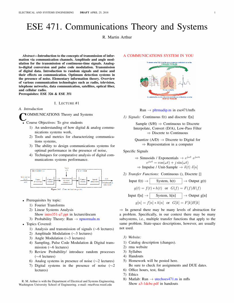
ELECTRICAL AND SYSTEMS ENGINEERING DRAFT APRIL 25, 2018 1 ESE 471. Communications Theory and Systems R. Martin Arthur Abstract—Introduction to the concepts of transmission of infor- mation via communication channels. Amplitude and angle mod- ulation for the transmission of continuous-time signals. Analog- to-digital conversion and pulse code modulation. Transmission of digital data. Introduction to random signals and noise and their effects on communication. Optimum detection systems in the presence of noise. Elementary information theory. Overview of various communication technologies such as radio, television, telephone networks, data communication, satellites, optical fiber, and cellular radio. Prerequisites: ESE 326 & ESE 351 I. LECTURE #1 A. Introduction C OMMUNICATIONS Theory and Systems • Course Objectives: To give students 1) An understanding of how digital & analog commu- nications systems work, 2) Tools and metrics for characterizing communica- tions systems, 3) The ability to design communications systems for optimal performance in the presence of noise, 4) Techniques for comparative analysis of digital com- munications systems performance. • Prerequisites by topic: 1) Fourier Transforms 2) Linear Systems Analysis Show intro351-a7.ppt in lecture/docum 3) Probability Theory: Run → npnormaln.m • Topics Covered: 1) Analysis and transmission of signals (∼6 lectures) 2) Amplitude Modulation (∼3 lectures) 3) Angle Modulation (∼3 lectures) 4) Sampling, Pulse Code Modulation & Digital trans- mission (∼6 lectures) 5) Review Probability/ introduce random processes (∼4 lectures) 6) Analog systems in presence of noise (∼2 lectures) 7) Digital systems in the presence of noise (∼2 lectures) R. M. Arthur is with the Department of Electrical and Systems Engineering, Washington University School of Engineering. e-mail: [email protected] A COMMUNICATIONS SYSTEM IN YOU Run → pltrmadip.m in ese471/mfls 1) Signals: Continuous f(t) and discrete f[n] Sample (S/H) ⇒ Continuous to Discrete Interpolate, Convert (D/A), Low-Pass Filter ⇒ Discrete to Continuous Quantize (A/D) → Discrete to Digital for ⇒ Representation in a computer Specific Signals ⇒ Sinusoids / Exponentials → e jωt e jωn e jωt = cos(ωt)+ j sin(ωt) ⇒ Impulse / Unit-Sample → δ(t) δ[n] 2) Transfer Functions: Continuous (), Discrete [] Input f(t) → System, h(t) → Output g(t) g(t)= f (t) * h(t) or G(f )= F (f )H(f ) Input f[n] → System, h[n] → Output g[n] g[n]= f [n] * h[n] or G[k]= F [k]H[k] ⇒ In general there may be many levels of abstraction for a problem. Specifically, in our context there may be many subsystems, i.e., multiple transfer functions that apply to the same problem. State-space descriptions, however, are usually not used. 3) Website: 1) Catalog description (changes). 2) rma website 3) Syllabus 4) Handouts 5) Homework will be posted here. Be sure to check for assignments and DUE dates. 6) Office hours, test, final 7) Ethics 8) Matlab: Run → utechoes471.m in mfls Show a3-1dcbe.pdf in handouts
Transcript of ELECTRICAL AND SYSTEMS ENGINEERING DRAFT APRIL 25, …A. Pulse Code Modulation Pulse-code modulation...
ELECTRICAL AND SYSTEMS ENGINEERING DRAFT APRIL 25, 2018 1
ESE 471. Communications Theory and SystemsR. Martin Arthur
Abstract—Introduction to the concepts of transmission of infor-mation via communication channels. Amplitude and angle mod-ulation for the transmission of continuous-time signals. Analog-to-digital conversion and pulse code modulation. Transmissionof digital data. Introduction to random signals and noise andtheir effects on communication. Optimum detection systems inthe presence of noise. Elementary information theory. Overviewof various communication technologies such as radio, television,telephone networks, data communication, satellites, optical fiber,and cellular radio.Prerequisites: ESE 326 & ESE 351
I. LECTURE #1A. Introduction
COMMUNICATIONS Theory and Systems
• Course Objectives: To give students1) An understanding of how digital & analog commu-
nications systems work,2) Tools and metrics for characterizing communica-
tions systems,3) The ability to design communications systems for
optimal performance in the presence of noise,4) Techniques for comparative analysis of digital com-
munications systems performance.
• Prerequisites by topic:1) Fourier Transforms2) Linear Systems Analysis
Show intro351-a7.ppt in lecture/docum3) Probability Theory: Run → npnormaln.m
• Topics Covered:1) Analysis and transmission of signals (∼6 lectures)2) Amplitude Modulation (∼3 lectures)3) Angle Modulation (∼3 lectures)4) Sampling, Pulse Code Modulation & Digital trans-
mission (∼6 lectures)5) Review Probability/ introduce random processes
(∼4 lectures)6) Analog systems in presence of noise (∼2 lectures)7) Digital systems in the presence of noise (∼2
lectures)
R. M. Arthur is with the Department of Electrical and Systems Engineering,Washington University School of Engineering. e-mail: [email protected]
A COMMUNICATIONS SYSTEM IN YOU
Run → pltrmadip.m in ese471/mfls
1) Signals: Continuous f(t) and discrete f[n]
Sample (S/H) ⇒ Continuous to DiscreteInterpolate, Convert (D/A), Low-Pass Filter
⇒ Discrete to Continuous
Quantize (A/D) → Discrete to Digital for⇒ Representation in a computer
Specific Signals
⇒ Sinusoids / Exponentials → ejωt ejωn
ejωt = cos(ωt) + j sin(ωt)⇒ Impulse / Unit-Sample → δ(t) δ[n]
2) Transfer Functions: Continuous (), Discrete []
Input f(t) → System, h(t) → Output g(t)
g(t) = f(t) ∗ h(t) or G(f) = F (f)H(f)
Input f[n] → System, h[n] → Output g[n]
g[n] = f [n] ∗ h[n] or G[k] = F [k]H[k]
⇒ In general there may be many levels of abstraction fora problem. Specifically, in our context there may be manysubsystems, i.e., multiple transfer functions that apply to thesame problem. State-space descriptions, however, are usuallynot used.
3) Website:1) Catalog description (changes).2) rma website3) Syllabus4) Handouts5) Homework will be posted here.
Be sure to check for assignments and DUE dates.6) Office hours, test, final7) Ethics8) Matlab: Run → utechoes471.m in mfls
Show a3-1dcbe.pdf in handouts
2 ELECTRICAL AND SYSTEMS ENGINEERING DRAFT APRIL 25, 2018
II. LECTURE #2
Binary Communications
1) Receiver Operating Characteristic• For s(t) to r(t) in Fig 7-1 of Couch
Run → npnormaln.m• Change signal levels and noise powers for VT = 0
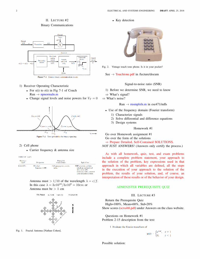
2) Cell phone• Carrier frequency & antenna size
TABLE 1-2 (cont.)
Frequency Banda
0.3- 3 GHz
Designation
Ultrahigh frequency (UHF)
Propagation Characteristics
LOS propagation, cosmic noise
Typical Uses
UHF television, cellular telephone, navigational aids, radar, GP S, microwave links, personal communication systems
Antenna must > 1/10 of the wavelength λ = c/f .In this case λ = 3x10¹⁰/3x109 = 10cm orAntenna must be > 1 cm
Fig. 1. Fractal Antenna [Nathan Cohen].
• Key detection
Fig. 2. Vintage touch tone phone. Is it in your pocket?
See → Touchtone.pdf in /lecture/docum
Signal-to-noise ratio (SNR)
1) Before we determine SNR, we need to know⇒ What’s signal?
⇒ What’s noise?
Run → rnsmplsfn.m in ese471/mfls
• Use of the frequency domain (Fourier transform)1) Characterize signals2) Solve differential and difference equations3) Design systems
Homework #1
Go over Homework assignment #1Go over the form of the solutions⇒ Prepare Detailed, Self-Contained SOLUTIONS.
NOT JUST ANSWERS! (Answers only certify the process.)
As with all homework, quiz, test, and exam problemsinclude a complete problem statement, your approach tothe solution of the problem, key expressions used in thatapproach in which all variables are defined, all the stepsin the execution of your approach to the solution of theproblem, the results of your solution, and, of course, aninterpretation of those results or of the behavior of your design.
ADMINISTER PREREQUISITE QUIZ
III. LECTURE #3
Return the Prerequisite QuizHigh=100%, Mean=68%, Std=20%
Show scores (scrssb8.pdf) under Answers on the class website.
Questions on Homework #1Problem 2-15 description from the text
Possible solution:

ARTHUR: COMMUNICATIONS THEORY AND SYSTEMS APRIL 25, 2018 3
• Problem Statement:Find W(f) the Fourier transform of w(t)
• Methodss : Using the definition of the Fourier transform
• Results: See W(f) given above• Interpretation:
Your comments on the meaning of the results, if any.• PLOTS BELOW ARE NOT REQUIRED
-0.5 0 0.50
2
4
6
Mag
nitu
de
W(f)
-0.5 0 0.5-80
-60
-40
-20
0
Normalized frequency
Pha
se, R
adia
ns
-0.5 0 0.50
2
4
6
Mag
nitu
de
W(f)
-0.5 0 0.5-2
-1
0
1
2
Normalized frequency
Pha
se, R
adia
ns
Fig. 3. Left, w(t) for t=0 to 10. Right, w(t) for t=1 to 10.
IV. LECTURE #4
Go over Homework #2Questions on the Quiz
A. Sampling & Interpolation
1) Sample theorem2) Interpolation
• sinc interpolation function• Padding with zeros (interpft in Matlab)
Run → demosine.m in ese471/mflsRun → demontrr.m in ese471/mflsRun → deomntrs.m in ese471/mfls
V. LECTURE #5
Questions on Homework #1
A. Orthogonal functions and the Fourier series
B. Pulse Amplitude Modulation
ADMINISTER HOMEWORK QUIZ #1
VI. LECTURE #6
Go over Quiz #1 [High=96, Low=28, Mean=76. Std=30]Run → qz1sb8.m
Orthogonal functions revisited
Exponentials & the Fourier seriesRun → rectsine.m
A. Pulse Code Modulation
Pulse-code modulation (PCM) is a method used to digitallyrepresent sampled analog signals. It is the standard form ofdigital audio in computers, compact discs, digital telephonyand other digital audio applications.
B. Pulse Code Words and Quantization Effects
VII. LECTURE #7
Quiz #1 phase
F (jΩ) = −e5(α+jΩ)
α+ jΩ= −e
5α ej5Ω
α+ jΩ= −e5α cos(5Ω) + j sin(5Ω)
α+ jΩ
φ(Ω) = − tan−1[sin(5Ω)/ cos(5Ω)]+tan−1(Ω/α) = −5Ω+tan−1(Ω/α)
Run → qz1sb8.m with analog phase calculation

4 ELECTRICAL AND SYSTEMS ENGINEERING DRAFT APRIL 25, 2018
A. Quantization Noise
B. Logarithmic Compression Make SNR nearly independenton signal power
1) A Law in North America & Japan:
y =sgn(m)
ln(1 + µ)ln(1 + µ| m
mp|)
2) µ Law in Europe:
C. Transmission Line Model
Run Circuit simulation → fig95.asc in /mfls
VIII. LECTURE #8
Go over Homework #3Questions on Homework #2
Run → Example3 07.m in /bkg/couchmfls
Sampling with an impulse train
ADMINISTER HOMEWORK QUIZ #2
IX. LECTURE #9
Show Quiz ScoresGo over Quiz #2 [High=120, Low=64, Mean=92. Std=16]First null bandwidth for rectangular pulses
BPCM ≥ nB
where B is the bandwidth of the analog channel. Reductionof the PCM signal bandwidth causes inter-symbol interference(ISI).
Run → nullbw.m to see First-Null pulse
Communication System : Channel
• Acts as a filter• May be nonlinear• Signal is contaminated by noise• SNR decreases with propagation
Manchester Signaling as an example of binary line codingSignaling
• Unipolar (1 high, 0 zero)• Polar (equal ± levels for 1’s and 0’s)• Bipolar (1’s alternating ± values, 0 zero)• Manchester (1 ± half bit, 0 reverse)
PSDMC(f) = A2Tb(sinc(πfTb/2)2 sin2(πfTb/2) .
Run → P3 07.m /in bkg/couchmfls
Run → fseries.m -> Fourier series on websiteApproximations for Triangle, Square & Rectified sine
ARTHUR: COMMUNICATIONS THEORY AND SYSTEMS APRIL 25, 2018 5
X. LECTURE #10
A. Baseband Pulse Transmission
The equivalent impulse response of the system is
he(t) = h(t) ∗ hT (t) ∗ hC(t) ∗ hR(t)
In the frequency domain convolution becomes multiplication
He(f) = H(f)HT (f)HC(f)HR(f)
where for a flat-topped pulse is H(f) = Ts sinc(πTSf) andHR(f) = He(f)
H(f)∗HT (f)∗HC(f) .He(f) is chosen to minimize Intersymbol Interference (ISI).
B. Channel Distortion
Example: Low-pass filter channel (RC circuit)Nyquist’s First Method: If
he(t) = sinc(πfst)↔ He(f) flat from -B to B, 0 otherwise
there will be no ISI, but He(f) is not realizable (noncausal).
C. Raised Cosine-Rolloff Nyquist Filter
One practical way to reduce ISIRaised Cosine filter with a rolloff factor r = f∆/f0
and Baud D = 2B1+r , where B is the system bandwidth.
Matlab ⇒ doc tukeywinRun → raisedcos.m in /mfls
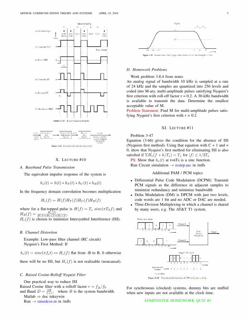
D. Homework Problems
Work problem 3.8.4 from notesAn analog signal of bandwidth 10 kHz is sampled at a rateof 24 kHz and the samples are quantized into 256 levels andcoded into M-ary, multi-amplitude pulses satisfying Nyquist’sfirst criterion with roll-off factor r = 0.2. A 30-kHz bandwidthis available to transmit the data. Determine the smallestacceptable value of M.Problem Statement: Find M for multi-amplitude pulses satis-fying Nyquist’s first criterion with r = 0.2.
XI. LECTURE #11
Problem 3-47Equation (3-66) gives the condition for the absence of ISI(Nyquists first method). Using that equation with C = 1 and =0, show that Nyquist’s first method for eliminating ISI is alsosatisfied if ΣHe(f + k/Ts) = Ts for |f | ≤ 1/2Ts
PS: Show that he(t) at t=nTs is a sinc function.Run Circuit simulation → rcstep.asc in /mfls
Additional PAM / PCM topics
• Differential Pulse Code Modulation (DCPM): TransmitPCM signals as the difference in adjacent samples tominimize redundancy and minimize bandwidth
• Delta Modulation (DM) is DPCM with just two levels,code words are 1 bit and no ADC or DAC are needed.
• TIme-Division Multiplexing in which a channel is sharedby many users, e.g. The AT&T T1 system.
For synchronous (clocked) systems, dummy bits are stuffedwhen new inputs are not available at the clock time.
ADMINISTER HOMEWORK QUIZ #3

6 ELECTRICAL AND SYSTEMS ENGINEERING DRAFT APRIL 25, 2018
XII. LECTURE #12
Show Quiz ScoresGo over Quiz #3 [High=100, Low=60, Mean=88. Std=12]
Go over Homework #4Run → bwanlp.m in /mfls for 4.9 & 4.19
Bandpass Signaling
Modulation
Rerun → utechoes471.m in /mfls
• Modulated signals
1) Representation2) Spectra
• Bandpass Sample Theorem
XIII. LECTURE #13
Questions on HW#4Rerun → bwanlp.m in /mfls
Physical bandpass waveform v(t) representations
v(t) = Reg(t)ejwct
where fc is the carrier frequencyand g(t) is the complex envelope of v(t).Alternate representations
• Eq. 4-1b
v(t) = |g(t)| cos[ωct+ θ(t)]
• Eq, 4-1c
v(t) = x(t) cosωct− y(t) sinωct
• Note that
g(t) = x(t) + jy(t) = |g(t)|ej∠g(t)
where
x(t) = Reg(t) ≡ |g(t)| cos θ(t)
y(t) = Img(t) ≡ |g(t)| sin θ(t)
θ(t) , ∠g(t) = tan−1 y(t)
x(t)
Rererun → utechoes471.m in /mfls
XIV. LECTURE #14
Questions on HW#4Rerererun → utechoes471.m in /mfls
Spectrum and delay of v(t)
Modulation
For message m(t), from Table 4-1• Amplitude
1) DSB-AM: Standard Amplitude ModulationMapping g(m) same as x(t):
Ac[1 +m(t)]
2) DSB-SC: Double Sideband - Suppressed CarrierMapping g(m) same as x(t):
Ac[m(t)]
3) SSB-AM-SC: Single-Sideband - Suppressed CarrierMapping g(m):
Ac[m(t) + jm(t)] ,
where [m(t)] is the Hilbert transform.• Phase
Mapping g(m):Ace
jDpm(t)
• FrequencyMapping g(m):
AcejDf
∫ f−∞m(τ)dτ
Single sideband (SSB) forms of Phase, frequency, Envelopeand Square law modulation use the Hilbert transform
Double Sideband AM Modulation
Run → Example4 03rma in bkg/couchmfls
XV. LECTURE #15
Bandpass FilteringQuestions on HW#4• Problem 4-09, v2(t)
Rerun → bwanlp.m in /mfls
• Problem 4-11http://www.linear.com/designtools/ (or e.g. Simulink)

ARTHUR: COMMUNICATIONS THEORY AND SYSTEMS APRIL 25, 2018 7
Run → prb411.asc in /mfls• Problem 4-15. If
v(t) = Reg(t)ejwct
then, given the properties of the Fourier transform,Eqn. 4-12 follows
V (f) = 0.5[G(f − fc) +G∗(−f − fc)]
Note that
0.5(a+jb+[a+jb]∗) = 0.5(a+jb+a−jb) = 0.5(2a) = a
• Eqn. 4-26 follows from Eqn. 4-12 above
DSB-AM Power & Demodulation
ADMINISTER HOMEWORK QUIZ #4
XVI. LECTURE #16
TEST PREPARATION
1) Test - 21 March 2018• Closed-book, closed-notes, closed-aid-memoir• 4 Problems of equal value, similar to quiz problems• Covers Homework Assignments #1 thru #3
R1
400L1
1.583m
C2
1µ
V1
ac 1
.ac lin 100 3500 4500
--- C:\1a\educ\ese471\mfls\prb411.asc ---
Fig. 4. Problem 4.11 Bandpass Filter
• & related text and class material2) Go over Quiz #4: High=100,Low=76,µ = 91, σ = 83) Binary & M-ary PCM
Binary: Run → Example4 07 in bkg/couchmflsM-ary: Run → Example4 08 in bkg/couchmfls
4) Sampling / InterpolationSample TheoremRun → sincidlp.m in /mfls
5) SNR for n-bit quantization
SNRdB = 6.02n+ α
Uniformα = 4.77− 20 log(V/xrms)
µ law for sufficiently large inputs
α = 4.77− 20 log[ln(1 + µ)]
where V is peak design level (range) of the quantizerand xrms is the rms value of the input analog signal.
XVII. SESSION #17 - TEST
21 March 2018Closed-book, closed-notes, closed-aid-memoir
4 Problems
XVIII. SESSION #18 - LECTURE
Go over Homework #5
Modulated Systems
• Double Sideband, Suppressed Carrier [m(t) zero DC]
s(t) = Acm(t) cosωct↔ S(f) =Ac2
[M(f−fc)+M(f+fc)]
1) More expensive (product) demodulator requiredthan for DSB.For example a PLL or squaring loop as shown inFig. 5-3, may be used to recover the carrier.
2) DSB-SC power is 4x that of standard AM signal3) For m(t) polar binary
s(t) is a BPSK (binary phase shift keying) signal• Single Sideband
An upper sideband signal has a zero-valued spectrumfor |f | < fc, the carrier frequencyUsing the complex envelope, g(t) = Ac[m(t) + jm(t)]for the USSB. m(t) is the Hilbert transform of m(t).
1) AM component|g(t)| = Ac
√m2(t) + m2(t)

8 ELECTRICAL AND SYSTEMS ENGINEERING DRAFT APRIL 25, 2018
2) PM component
∠g(t) = tan−1 m(t)
m(t)
3) vout (with a product detector & θo set to zero)
vout = KRe[g(t)e−jθo ] = KAcm(t)
Line codes: Use roll-off pulse shapes to limit bandwidth.Run → utechoes471.m in /mfls
• Angle modulationFor complex envelope g(t) where
g(t) = Acejθ(t)
The angle-modulated signal is
s(t) = Ac cos[ωct+ θ(t)]
1) PM: θ(t) = Dpm(t) in radians/volt2) FM: θ(t) = Df
∫∞−∞m(τ)dτ in radians/volt-sec
XIX. SESSION #19 - LECTURE
Show scores (tstsb8.pdf) under Answers on the class website
Go over TEST: High=86, Low=40, µ = 68, σ = 10
PM - FM relations
mf (t) =Dp
Df
dmp(t)
dt; mp(t) =
Df
Dp
∫ t
−∞mf (τ)dτ
Instantaneous frequency of a bandpass signals(t) = R(t) cosψ(t), where ψ(t) = ωc(t) + θ(t) is
fi(t) =1
2π
dψ(t)
dt
Run → Example5 05rma in bkg/couchfiles
XX. SESSION #20 - LECTURE
Go through Example 5-6 in the textRun → Example5 06 in bkg/couchfiles
Angle-modulated bandwidth BT (98% power)
BT ≈ 2(β + 1)B
where β is the phase modulation index & B is the bandwidthof the modulating signal.
Questions on HW#5
Angle Modulation Approximations (|θ(t)| < 0.2 rad)
• Narrowband Angle Modulation
g(t) = Acejθ(t) ≈ Ac[1 + jθ(t)]
• Wideband Frequency Modulation
Can be generated from the NBFM signal using frequencymultiplication (Armstrong’s method).See Table 1-1, 1933 Armstrong invents FM.
s(t) ≈ Ac cos[wct+Df
∫ t
−∞m(τ)dτ ]
For Vp, the peak triangle voltage
Binary Modulated Bandbpass Signaling
• On-Off Keying (OOK) g(t) = Acm(t)Null-to-null bandwidth BT = 2RFor R = 1/Tb and rolloff r,the absolute baseband bandwidth B = 0.5(1 + r)R.Transmission bandwidth BT = (1 + r)R
• Binary Phase-Shift Keying (BPSK)s(t) = Ac cos[ωct+Dpm(t)] for m(t) polar basebandTo maximize the power in the data term∆θ = Dp = π/2, so that
s(t) = −Acm(t) sin(ωct) & g(t) = jAcm(t)
Equivalent to DSB-SC with a polar baseband waveform.Null-to-null BW=2R the same as OOK.
• Frequency-Shift Keying (FSK)Discontinuous or Continuous
• Minimum-Shift Keying (MSK & GMSK)MSK is continuous FSK with modulation index h=0.5
1) Binary 1: 0 < t < Tb; s1(t) = Ac cos(ω1t+ θ1)2) Binary 0: 0 < t < Tb; s1(t) = Ac cos(ω2t+ θ2)
3) For orthogonality∫ Tb
0s1(t)s2(t)dt = 0, so that
4) sin[2πh+(θ1+θ2)−(θ1−θ2)]2πh = 0 and
5) Peak deviation frequency ∆F = 14Tb
= R/4
XXI. SESSION #21 - LECTURE
Go over Homework #6Homework #5
1) Problem 5.57 in the rextRun → P5-57rma in bkg/couchfiles
2) Problem 6.68 in the textRun → P5-68rma in bkg/couchfiles
ADMINISTER HOMEWORK QUIZ #5
ARTHUR: COMMUNICATIONS THEORY AND SYSTEMS APRIL 25, 2018 9
XXII. SESSION #22 - LECTURE
Go over Quiz #5: High=100,Low=32,µ = 76, σ = 20
Questions on HW#6Run → erfcdemo in /mflsRun → prb71 in /mfls
Syllabus changes: No Quiz #7, Matlab ExerciseHandouts Ex-1 (Hilbert transform and SSB worked in class)MatLab Ex-5 (Frequency Modulation, due Friday 27Apr18)Run → Ex8-1 in /mfls
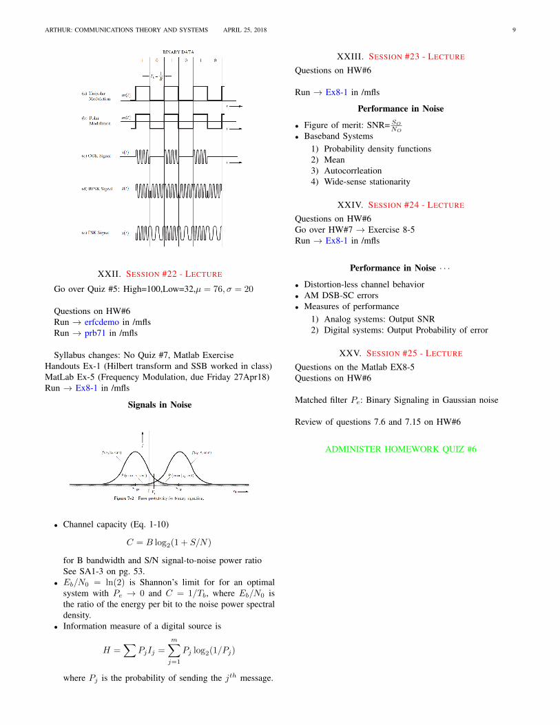
Signals in Noise
• Channel capacity (Eq. 1-10)
C = B log2(1 + S/N)
for B bandwidth and S/N signal-to-noise power ratioSee SA1-3 on pg. 53.
• Eb/N0 = ln(2) is Shannon’s limit for for an optimalsystem with Pe → 0 and C = 1/Tb, where Eb/N0 isthe ratio of the energy per bit to the noise power spectraldensity.
• Information measure of a digital source is
H =∑
PjIj =
m∑j=1
Pj log2(1/Pj)
where Pj is the probability of sending the jth message.
XXIII. SESSION #23 - LECTURE
Questions on HW#6
Run → Ex8-1 in /mfls
Performance in Noise
• Figure of merit: SNR= SO
NO
• Baseband Systems1) Probability density functions2) Mean3) Autocorrleation4) Wide-sense stationarity
XXIV. SESSION #24 - LECTURE
Questions on HW#6Go over HW#7 → Exercise 8-5Run → Ex8-1 in /mfls
Performance in Noise · · ·
• Distortion-less channel behavior• AM DSB-SC errors• Measures of performance
1) Analog systems: Output SNR2) Digital systems: Output Probability of error
XXV. SESSION #25 - LECTURE
Questions on the Matlab EX8-5Questions on HW#6
Matched filter Pe: Binary Signaling in Gaussian noise
Review of questions 7.6 and 7.15 on HW#6
ADMINISTER HOMEWORK QUIZ #6

10 ELECTRICAL AND SYSTEMS ENGINEERING DRAFT APRIL 25, 2018
XXVI. SESSION #26 - LECTURE
Go over Quiz #6: High=100, Low=64, µ = 89, σ = 3Questions on EX8-5
Baseband Binary Systems in Noise
Problem 7-23Digital data are to be transmitted over a toll telephone systemusing BPSK. Regenerative repeaters are spaced 50 miles apartalong the system. The total length of the system is 600 miles.The telephone lines between the repeater sites are equalizedover a 300- to 2,700-Hz band and provide an Eb/N0 (Gaussiannoise) of 15 dB to the repeater input. (a) Find the largest bitrate R that can be accommodated with no ISI. (b) Find theoverall Pe for the system. (Be sure to include the receiver atthe end of the system.)
XXVII. SESSION #27 - LECTURE
Questions on EX8-5Final Reference Material in HandoutsProblems relevant to the final exam• An angle-modulated signal with carrier frcquency ωc =
2π × 106 is described by the equation φEM (t) =10 cos(ωct − 0.3 cos 200πt) a) Find the power of themodulated signal. b) Find the frequency deviation ∆f . c)Find the phase deviation ∆φ. d) Estimate the bandwidthof φEM (t).
• A signal m(t) with a uniform PSD bandlimited to 4 kHzDSB-SC modulates a carrier of fc = 500 kHz. The mod-ulated signal is transmitted over a distortionless channelwith a noise PSD Sn(ω) = 1/(ω2 + a2), (a = 106π).The useful signal power at the receiver input is 1µW .The received signal is bandpass filtered, multiplied by2 cos(ωct), and then low-pass filtered to obtain the outputso(t) + no(t). Determine the output SNR.
Final - 9 May 2018
• Closed-book, closed-notes, closed-aid-memoir• 4 Problems of equal value, similar to test problems• Covers Homework Assignments #4 thru #7 &• Related text and class material• Comprehensive with emphasis on material since the test
XXVIII. SESSION #28 - FINAL
May 9, 1:00-3:00 PM in Cupples I, Rm 115