ELECTRIC STRETCHER SERIE PC-750 // STRETCHER …promeba.com/wp-content/uploads/2016/04/MANUAL...04.5...
74
USER GUIDE ELECTRIC STRETCHER SERIE PC-750 // STRETCHER SUPPORT SERIE PB-720 Review 01/16
Transcript of ELECTRIC STRETCHER SERIE PC-750 // STRETCHER …promeba.com/wp-content/uploads/2016/04/MANUAL...04.5...

USER GUIDE
ELECTRIC STRETCHER SERIE PC-750 // STRETCHER SUPPORT SERIE PB-720
Review 01/16


USER GUIDE // STRETCHER PC-750 + SUPPORT PB-720Review 01/16
3
01 INTRODUCTION
01.1 Using this manual 0501.2 Technical data sheet 06
02 INSTALLATION
02.1 Transport and unpacking 1002.2 Anchorage points 1102.3 Connection to the mains power supply 1202.4 Stretcher’s launch 13
03 OPERATION
03.1 Commands of the support PB-720 1403.2 Commands of the support PB-725 1503.3 Commands of the stretcher PC-750 1603.4 Commands of the stretcher PC-755 1703.5 Elements of the manual system PB-720 / PB-725 1803.6 Elements of the manual system PC-750 / PC-755 1903.7 Loading and unloading operation 2003.8 Control panel 2103.9 Breakdowns 2203.10 Troubleshooter 23
04 MOUNTING AND COMPONENTS
04.1 Main exploded of stretcher PC-750 / PC-755 2404.2 Main exploded of support PB-720 / PB-725 2504.3 Bill of lower ensamble PC-750 / PC-755 2604.4 Exploded views of lower ensamble PC-750 / PC-755 2704.5 Bill of upper ensamble PC-750 2804.6 Exploded views of upper ensamble PC-750 3104.7 Bill of upper ensamble PC-755 3204.8 Exploded views of upper ensamble PC-755 3304.9 Bill of control panel set PC-750 / PC-755 3404.10 Exploded views of control panel set PC-750 / PC-755 3504.11 Bill of extensible frame set PC-750 / PC-755 3604.12 Exploded views of extensible frame set PC-750 / PC-755 3704.13 Bill of batteries cabinet set PC-750 / PC-755 3804.14 Exploded views of batteries cabinet set PC-750 / PC-755 3904.15 Bill of left handrail ensamble PC-750 4004.16 Exploded views of left handrail ensamble PC-750 4104.17 Bill of right handrail ensamble PC-750 4204.18 Exploded views of right handrail ensamble PC-750 4304.19 Bill of headrest set of stretcher’s loading PC-750 / PC-755 4404.20 Exploded views of headrest set of stretcher’s loading PC-750 / PC-755 4504.21 Bill of stretcher’s bed set PC-750 4604.22 Exploded views of stretcher’s bed set PC-750 47
INDEX
USER GUIDE // STRETCHER PC-750 + SUPPORT PB-720Review 01/16
4
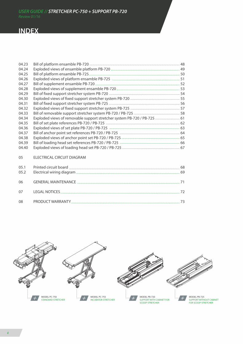
04.23 Bill of platform ensamble PB-720 4804.24 Exploded views of ensamble platform PB-720 4904.25 Bill of platform ensamble PB-725 5004.26 Exploded views of platform ensamble PB-725 5104.27 Bill of supplement ensamble PB-720 5204.28 Exploded views of supplement ensamble PB-720 5304.29 Bill of fixed support stretcher system PB-720 5404.30 Exploded views of fixed support stretcher system PB-720 5504.31 Bill of fixed support stretcher system PB-725 5604.32 Exploded views of fixed support stretcher system PB-725 5704.33 Bill of removable support stretcher system PB-720 / PB-725 5804.34 Exploded views of removable support stretcher system PB-720 / PB-725 6104.35 Bill of set plate references PB-720 / PB-725 6204.36 Exploded views of set plate PB-720 / PB-725 6304.37 Bill of anchor point set references PB-720 / PB-725 6404.38 Exploded views of anchor point set PB-720 / PB-725 6504.39 Bill of loading head set references PB-720 / PB-725 6604.40 Exploded views of loading head set PB-720 / PB-725 67
05 ELECTRICAL CIRCUIT DIAGRAM
05.1 Printed circuit board 6805.2 Electrical wiring diagram 69
06 GENERAL MAINTENANCE 71
07 LEGAL NOTICES 72
08 PRODUCT WARRANTY 73
MODEL PC-750STANDARD STRETCHER
MODEL PC-755INCUBATOR STRETCHER
MODEL PB-720SUPPORT WITH CABINET FOR SCOOP STRETCHER
MODEL PB-725SUPPORT WITHOUT CABINET FOR SCOOP STRETCHER
INDEX
USER GUIDE // STRETCHER PC-750 + SUPPORT PB-720Review 01/16
5
01.1 Using of manual
The manual provides using and maintenance instruc-tions of the product, as well as the way of fixing minor faults that could appear.
It is recommended before the operation of the product to read carefully this manual in order to avoid damages caused by a misuse.
Do not lose this document, it should be accessible to any doubt that could appear by medical personnel.
Remember that a good use and maintenance are ne-cessary for the proper operation of the product.
Each product incorporates an identification sticker with the serial number and the model. Keep these numbers so that they can be indicated to the dealer if necessary.
01 INTRODUCTION
USER GUIDE // STRETCHER PC-750 + SUPPORT PB-720Review 01/16
6
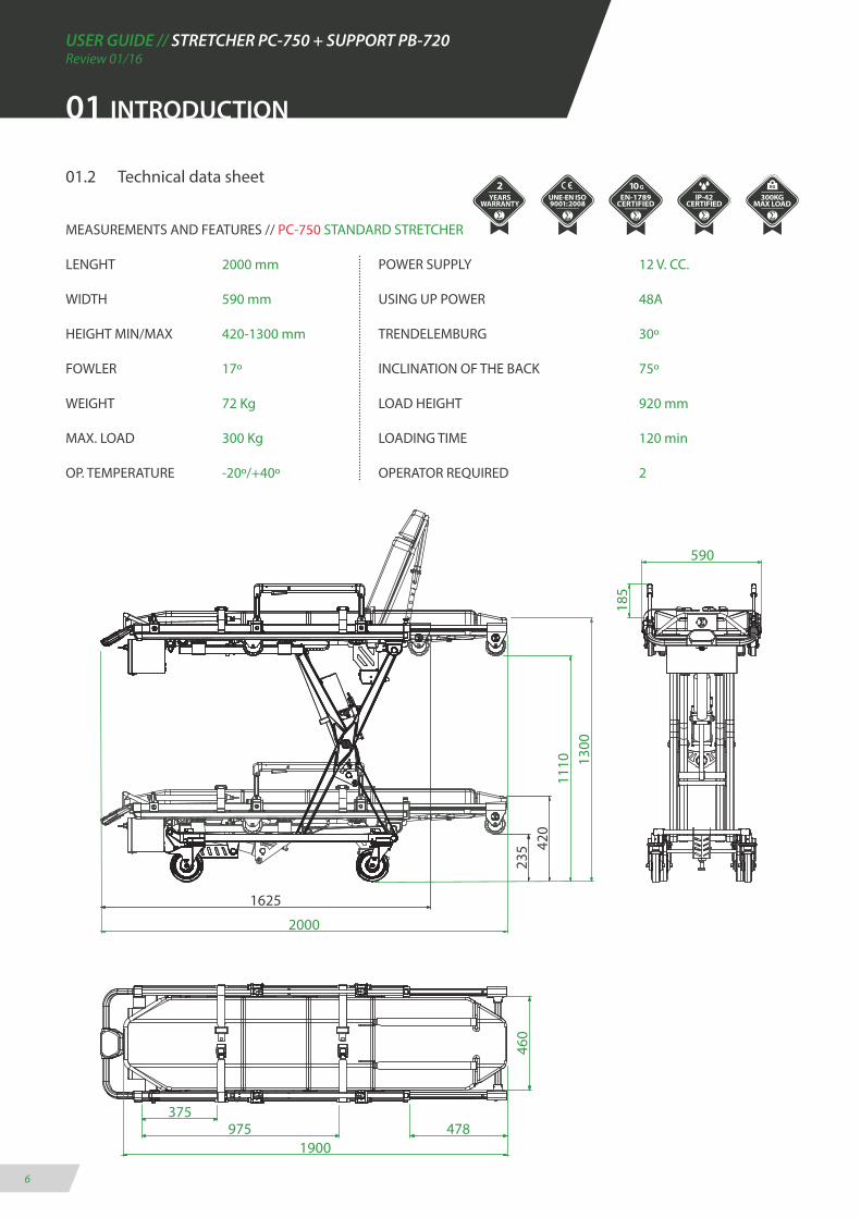
01.2 Technical data sheet
MEASUREMENTS AND FEATURES // PC-750 STANDARD STRETCHER
LENGHT 2000 mm POWER SUPPLY 12 V. CC.
WIDTH 590 mm USING UP POWER 48A
HEIGHT MIN/MAX 420-1300 mm TRENDELEMBURG 30º
FOWLER 17º INCLINATION OF THE BACK 75º
WEIGHT 72 Kg LOAD HEIGHT 920 mm
MAX. LOAD 300 Kg LOADING TIME 120 min
OP. TEMPERATURE -20º/+40º OPERATOR REQUIRED 2
01 INTRODUCTION

USER GUIDE // STRETCHER PC-750 + SUPPORT PB-720Review 01/16
7
MEASUREMENTS AND FEATURES // PC-755 INCUBATOR STRETCHER
LENGHT 2000 mm POWER SUPPLY 12 V. CC.
WIDHT 575 mm USING UP POWER 48A
HEIGHT MIN/MAX 390-1270 mm OPERATOR REQUIRED 1
WEIGHT 65 Kg LOAD HEIGHT 920 mm
MAX. LOAD 300 Kg LOADING TIME 120 min
OP. TEMPERATURE -20º/+40º TRAY MESUREMENTS 1765x525 mm
01 INTRODUCTION
575
20001765
525
390
235
1110 12
702375
375
USER GUIDE // STRETCHER PC-750 + SUPPORT PB-720Review 01/16
8
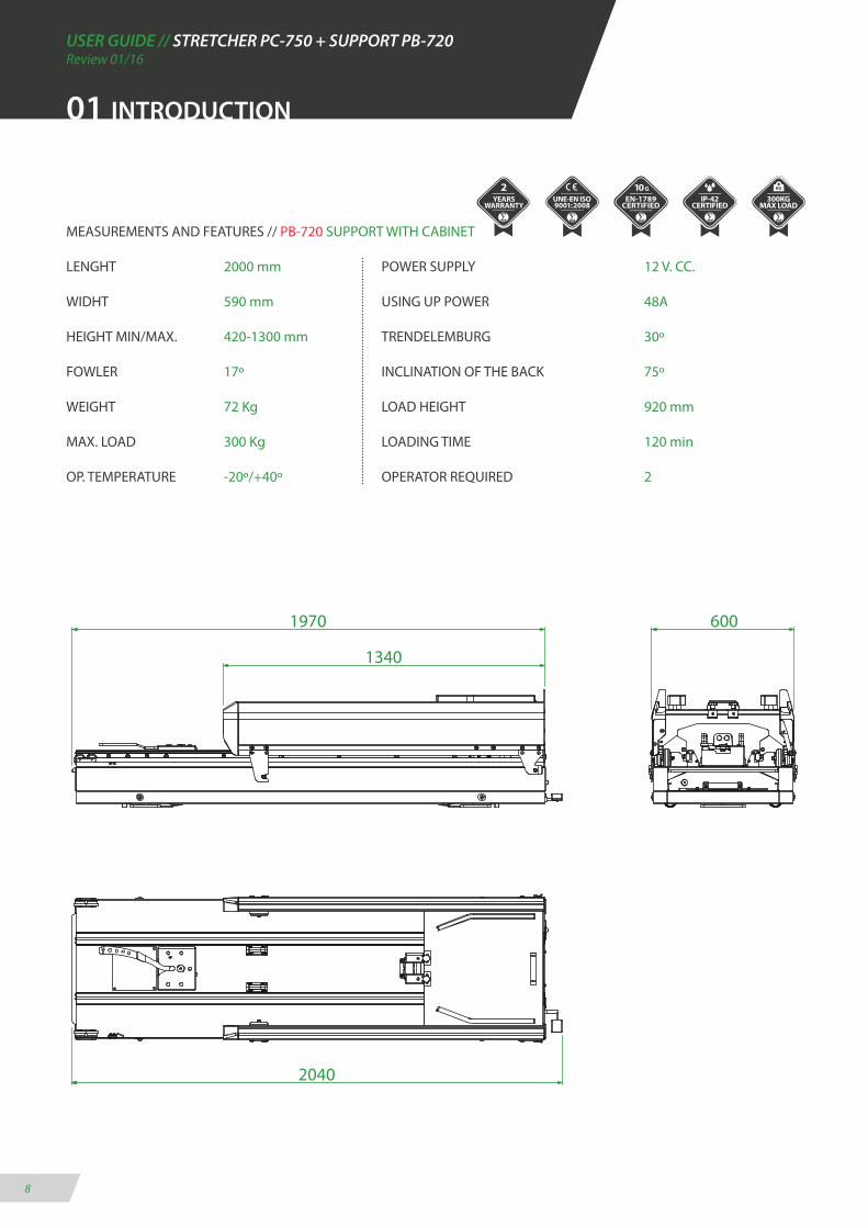
MEASUREMENTS AND FEATURES // PB-720 SUPPORT WITH CABINET
LENGHT 2000 mm POWER SUPPLY 12 V. CC.
WIDHT 590 mm USING UP POWER 48A
HEIGHT MIN/MAX. 420-1300 mm TRENDELEMBURG 30º
FOWLER 17º INCLINATION OF THE BACK 75º
WEIGHT 72 Kg LOAD HEIGHT 920 mm
MAX. LOAD 300 Kg LOADING TIME 120 min
OP. TEMPERATURE -20º/+40º OPERATOR REQUIRED 2
6001970
1340
2040
01 INTRODUCTION
USER GUIDE // STRETCHER PC-750 + SUPPORT PB-720Review 01/16
9
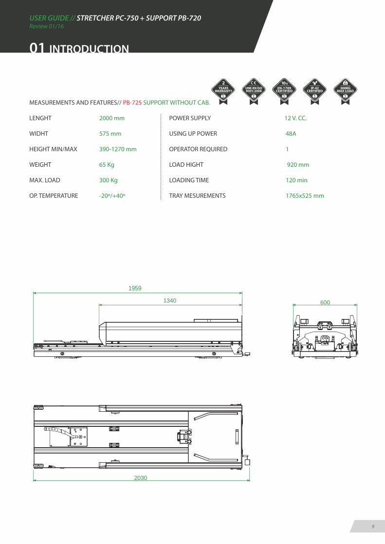
MEASUREMENTS AND FEATURES// PB-725 SUPPORT WITHOUT CAB.
LENGHT 2000 mm POWER SUPPLY 12 V. CC.
WIDHT 575 mm USING UP POWER 48A
HEIGHT MIN/MAX 390-1270 mm OPERATOR REQUIRED 1
WEIGHT 65 Kg LOAD HIGHT 920 mm
MAX. LOAD 300 Kg LOADING TIME 120 min
OP. TEMPERATURE -20º/+40º TRAY MESUREMENTS 1765x525 mm
1959
2030
600 1340
01 INTRODUCTION

USER GUIDE // STRETCHER PC-750 + SUPPORT PB-720Review 01/16
10
02 INSTALLATION
02.1 Transport and unpacking
First carefully remove the packaging to prevent the da-mage of the product. Take the wooden cover away and use a crane to move vertically.
1. Transport with a crane (high load)
· Thread tapes through the upper platform for its trans-port (as shown in graphs).
· Transport the load level following all the precepts and regulations for the transport of suspended loads.
2. Transport with a forklift
· Place a pallet or a flat surface under the stretcher su-pport and transport it transversely.
· Do not load the stretcher support directly on the fork-lift without a pallet or flat support surface.
· Do not load the support stretcher longitudinally on the forklift if a sufficiently long base is not available.
· Every set has been throughly inspected leaving the factory. To ensure that it has not been damaged during the transport, it is requested to carefully examine the interior and exterior, and in case of finding any dama-ge, communicate immediately to the installer.
· The stretcher and support set should be levelled for an optimum performance.
TRANSPORT WITH A CRANEFIX THE TAPES TO LEVEL THE LOAD WEIGHT
TRANSPORT WITH A FORKLIFTUSE ALWAYS A FLAT SUPPORT SURFACE

USER GUIDE // STRETCHER PC-750 + SUPPORT PB-720Review 01/16
11
02 INSTALLATION
02.2 Anchorage points
Before putting the stretcher support into operation, ensure that each and every anchorage points are pla-ced and clasped.
ANCHORE FOR PB-720 · PB-725(8 anchorage points)
180mm MÍNIMO
441mm MÁXIM
185
592
102 102 1274 1
59
2042
256
12,5 (X8)
LIMIT AMBULANCE FLOOR
FREE ZONE TO THE FLOOR
LIMIT AMBULANCE WALL
***IMPORTANT TO ITS INSTALLATION***
SREWS TO ATTACH ON THE FLOOR M12 S/NORMA DIN-7991 (8 UNITS)
BEFORE DRILLING ON THE FLOOR OF THE AMBULANCE, VERIFY THAT THE LATE-RAL MOVEMENT OF THE STRETCHER SUPPORT ARE PLACED ON 0 POSITION.
KEEP THE MINIMUM LIMITS INDICATED ON THE PLAN AND ENSURE OF AFFIXING THE SET ON THE REINFORCED CHASSIS AREA.
THE ELECTRIC INSTALLATION OF THE SET MUST BE COMPLETED WITH THE ELEC-TRICAL SYSTEM OF THE AMBULANCE DISCONNECTED.
READ THE INSTRUCTIONS MANUAL IN CASE OF ANY DOUBTS DURING THE INSTALLATION.
USE SCREWS DIN-7991 - M12 - 10.9

USER GUIDE // STRETCHER PC-750 + SUPPORT PB-720Review 01/16
12
02 INSTALLATION
02.3 Connection to the mains power supply PB-720 / PB-725
To make the connection follow the steps below.
Be particularly careful when the connecting the stretcher support to the required voltage of 12V and do not leave cables in passageways and or moving elements. It can provoke breakages, cuts and system failures.
A
Current cable 12V. CC.
Remove the plastic end of the BROWN (+) y BLUE (-) cables with a thread pee-ler to make the connection.
C
Use a power strip and a flathead srew-driver to connect the BROWN (+) y BLUE (-) wires together with the outlet of the ambulance.
To make the connection locate the black cable placed on the front side of the support stretcher.
MAKE SURE YOU HAVE THE POWER LINE PROPERLY PROTECTED AND ENSURE THE POWER ALONG THE LINE IS STABLE.
B
USER GUIDE // STRETCHER PC-750 + SUPPORT PB-720Review 01/16
13
02 INSTALLATION
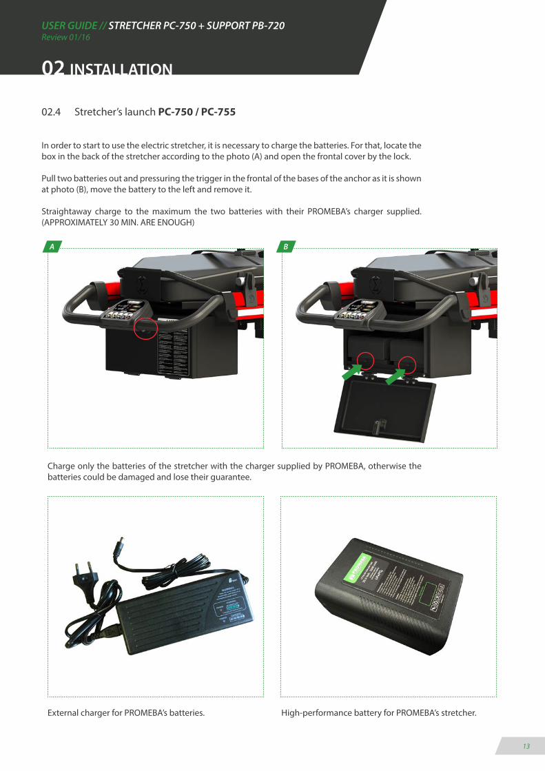
02.4 Stretcher’s launch PC-750 / PC-755
In order to start to use the electric stretcher, it is necessary to charge the batteries. For that, locate the box in the back of the stretcher according to the photo (A) and open the frontal cover by the lock.
Pull two batteries out and pressuring the trigger in the frontal of the bases of the anchor as it is shown at photo (B), move the battery to the left and remove it.
Straightaway charge to the maximum the two batteries with their PROMEBA’s charger supplied. (APPROXIMATELY 30 MIN. ARE ENOUGH)
A
Charge only the batteries of the stretcher with the charger supplied by PROMEBA, otherwise the batteries could be damaged and lose their guarantee.
B
External charger for PROMEBA’s batteries. High-performance battery for PROMEBA’s stretcher.
USER GUIDE // STRETCHER PC-750 + SUPPORT PB-720Review 01/16
14
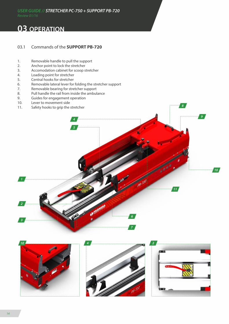
03.1 Commands of the SUPPORT PB-720
1. Removable handle to pull the support2. Anchor point to lock the stretcher3. Accomodation cabinet for scoop stretcher4. Loading point for stretcher5. Central hooks for stretcher6. Removable lateral lever for folding the stretcher support7. Removable bearing for stretcher support8. Pull handle the rail from inside the ambulance9. Guides for engagement operation10. Lever to movement side11. Safety hooks to grip the stretcher
03 OPERATION
4
7
10
1
2
6
8
10 4 2
3
9
5
11
USER GUIDE // STRETCHER PC-750 + SUPPORT PB-720Review 01/16
15
03 OPERATION
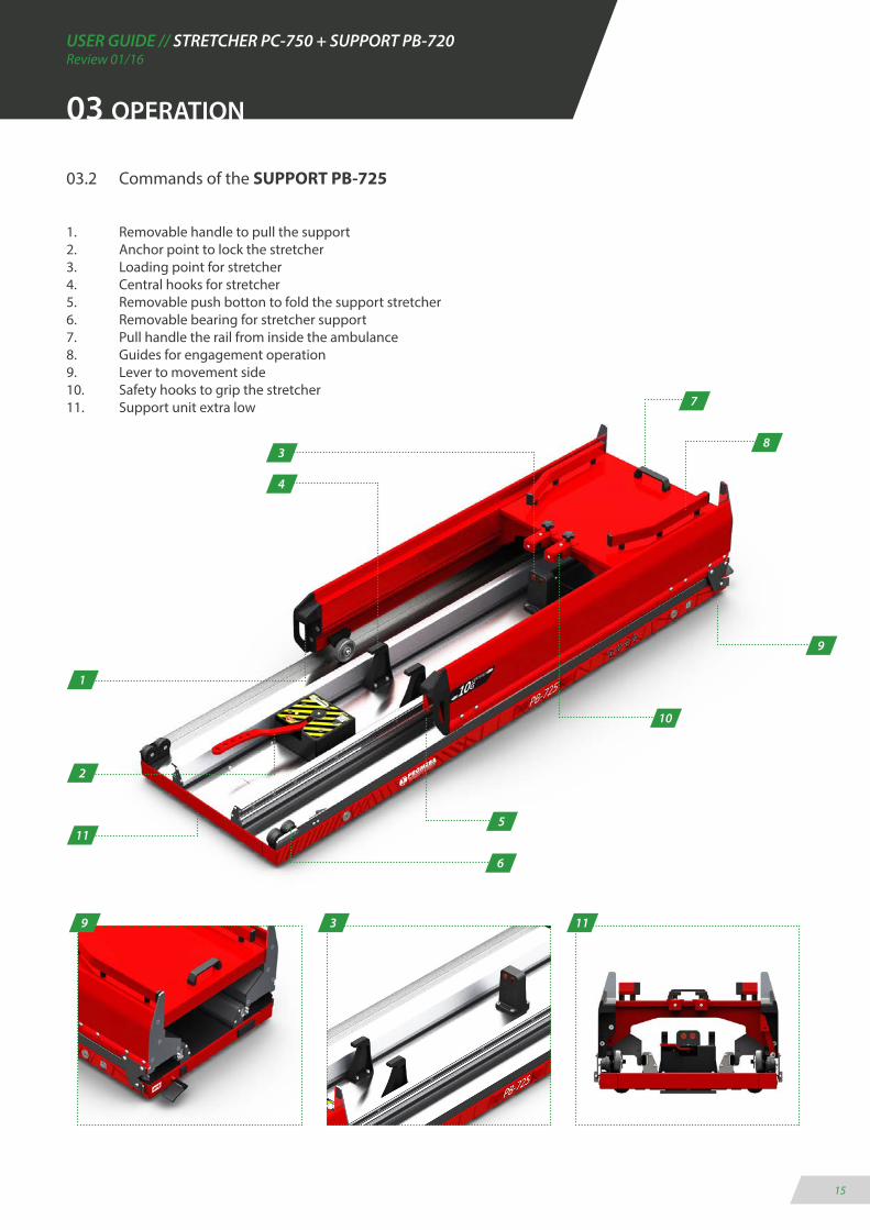
03.2 Commands of the SUPPORT PB-725
1. Removable handle to pull the support2. Anchor point to lock the stretcher3. Loading point for stretcher4. Central hooks for stretcher5. Removable push botton to fold the support stretcher6. Removable bearing for stretcher support7. Pull handle the rail from inside the ambulance8. Guides for engagement operation9. Lever to movement side10. Safety hooks to grip the stretcher11. Support unit extra low
3
6
9
1
2
5
7
9 3 11
8
4
10
11

USER GUIDE // STRETCHER PC-750 + SUPPORT PB-720Review 01/16
16
03.3 Commands of the STRETCHER PC-750
1. Foldable and reclining handrails2. Retractable belts on the backrest3. Touch control panel in the middle4. Batteries cabinet with lock5. Four lockable wheels6. Telescopic frame for maneuvering7. Bed with fowler and trendelemburg8. Folding and adjustable IV pole 9. Powerful LED lighting on the sides10. Emergency switch11. Belts with front locking push botton12. Automatic integrated charging system
2
5
11
38
4
1
6
03 OPERATION
7
9
1012
71012
USER GUIDE // STRETCHER PC-750 + SUPPORT PB-720Review 01/16
17
03 OPERATION
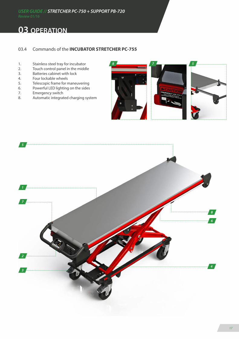
03.4 Commands of the INCUBATOR STRETCHER PC-755
1. Stainless steel tray for incubator2. Touch control panel in the middle3. Batteries cabinet with lock4. Four lockable wheels5. Telescopic frame for maneuvering6. Powerful LED lighting on the sides7. Emergency switch8. Automatic integrated charging system
4
1
2
3
5
6
7
8
578
USER GUIDE // STRETCHER PC-750 + SUPPORT PB-720Review 01/16
18
1640
300
03 OPERATION
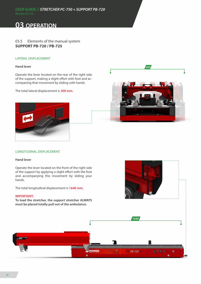
03.5 Elements of the manual system SUPPORT PB-720 / PB-725
LATERAL DISPLACEMENT
Hand lever
Operate the lever located on the rear of the right side of the support, making a slight effort with foot and ac-companing that movement by sliding with hands.
The total lateral displacement is 300 mm.
LONGITUDINAL DISPLACEMENT
Hand lever
Operate the lever located on the front of the right side of the support by applying a slight effort with the foot and accompanying this movement by sliding your hands.
The total longitudinal displacement is 1640 mm.
IMPORTANT:To load the stretcher, the support stretcher ALWAYS must be placed totally pull out of the ambulance.
USER GUIDE // STRETCHER PC-750 + SUPPORT PB-720Review 01/16
19
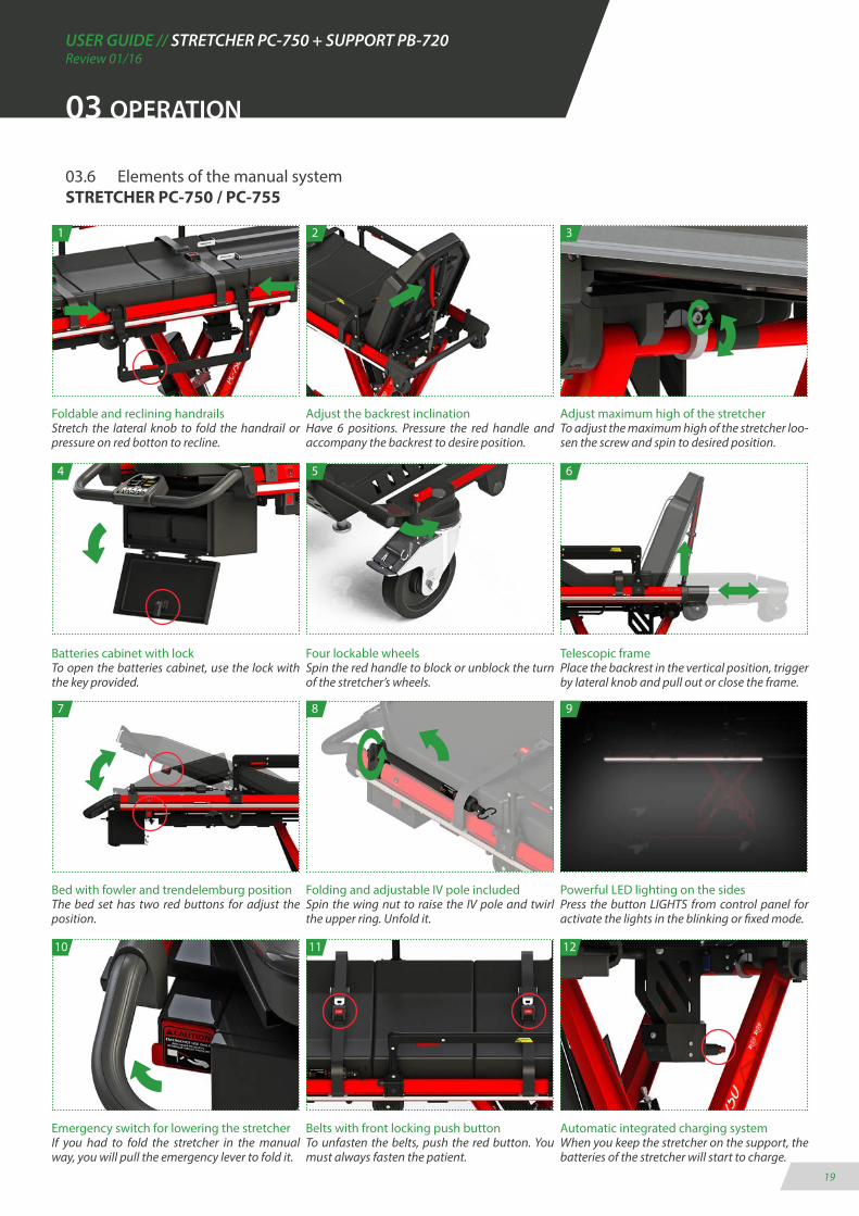
03.6 Elements of the manual system STRETCHER PC-750 / PC-755
03 OPERATION
Foldable and reclining handrailsStretch the lateral knob to fold the handrail or pressure on red botton to recline.
Batteries cabinet with lockTo open the batteries cabinet, use the lock with the key provided.
Bed with fowler and trendelemburg positionThe bed set has two red buttons for adjust the position.
Adjust the backrest inclinationHave 6 positions. Pressure the red handle and accompany the backrest to desire position.
Four lockable wheelsSpin the red handle to block or unblock the turn of the stretcher’s wheels.
Folding and adjustable IV pole includedSpin the wing nut to raise the IV pole and twirl the upper ring. Unfold it.
Adjust maximum high of the stretcherTo adjust the maximum high of the stretcher loo-sen the screw and spin to desired position.
Telescopic framePlace the backrest in the vertical position, trigger by lateral knob and pull out or close the frame.
Powerful LED lighting on the sidesPress the button LIGHTS from control panel for activate the lights in the blinking or fixed mode.
1
4
7
2
5
8
3
6
9
Emergency switch for lowering the stretcherIf you had to fold the stretcher in the manual way, you will pull the emergency lever to fold it.
Belts with front locking push buttonTo unfasten the belts, push the red button. You must always fasten the patient.
Automatic integrated charging systemWhen you keep the stretcher on the support, the batteries of the stretcher will start to charge.
10 11 12

USER GUIDE // STRETCHER PC-750 + SUPPORT PB-720Review 01/16
20
03 OPERATION
03.7 Loading and unloading operation
Starting from the position in which the support has been left after the loading of the stretcher into the ambulance (1):
UNLOADING· Pull the lever of the anchor point towards the left (A).· Automatically the stretcher will be free. Push it out the ambulance (B) until the su-pport are totally extract (2).· Use the control panel to power the stretcher. WAIT 2 SECONDS to activate the system and later push the UP button (C).· Once the stretcher will be in its highest position, which will be free (4).· Move away the stretcher in straight line until being completely out of the support.· Again, pick the support up into the ambulance by the lever placed on right side (C).
LOADING· Pull the support out the ambulance by lever of the anchor point (A).· Push the support by lateral handles until its maximum.· Move the stretcher closer towards the support in straight line (5) make sure the whe-els are placed like the image (D).· Push the DOWN button on the control panel of the stretcher (E) and after push right lateral lever of the support (C) to put the set into the ambulance.· Secure the stretcher is fasten on the anchor point (A) and anchor point is on close position.· Verify the stretcher are charging, pushing the POWER button.
A
C
3
2
1
4
5
B
D
C
UPE
DOWN
THE FRONT WHEELS OF THE STRETCHER MUST BE LOCKED WHEN THE LOADING/UNLOADING OPERATION ARE EXECUTED.
ON THE CONTRARY, IT IS POSSIBLE IM-PORTANT ELEMENTS OF THE STRETCHER
COULD BE DAMAGED.

USER GUIDE // STRETCHER PC-750 + SUPPORT PB-720Review 01/16
21
03 OPERATION
03.8 Control panel
CONTROL PANEL FUNCTION
All the electrical functions of the stretcher are controlled from the touch control panel placed on the back of the stretcher.
See its functions in the following graphic:
LED VERDE (BOTÓN UP)
LED VERDE (BOTÓN DOWN) LED ROJO/AMBAR/VERDE (ESTADO DE LAS BATERÍAS)
LED ROJO(FALLO BATERÍAS)
LED ROJO(BATERÍAS DESCONECTADAS)
LED AMBAR(FALLO ELÉCTRICO)
LED AZUL(LUCES ENCENDIDAS)
PRIMERA PULSACIÓN(encendido)SEGUNDA PULSACIÓN (2 seg.)(apagado)
PRIMERA PULSACIÓN(activar zumbador)SEGUNDA PULSACIÓN(apagar zumbador)
PULSACIÓN CONTÍNUA(subir la camilla)-Encender testigo led-
PULSACIÓN CONTÍNUA(bajar la camilla)-Encender testigo led-
ERRORS KEY OF CONTROL PANEL
The led indicator of batteries status indicates possible errors of the system.In the following table, it is described the error according to its combination:
1. ERROR OF CONNECTION BETWEEN STRETCHER AND SUPPORT2. ERROR FOR ELECTRIC SUPPLING ON THE SUPPORT3. ERROR FOR OVERCHARGING BATTERIES4. ERROR TIMEOUT FOR LOADING5. ERROR MOVING UP FOR EXCESSIVE TIME6. ERROR MOVING DOWN FOR EXCESSIVE TIME7. ERROR IN CONTROL DRIVER OF STRETCHER8. ERROR IN ENGINE TO EXCEED MAX. INTENSITY9. ERROR IN ENGINE FOR LOW TENSION10. ERROR FOR EXCEED LOAD
USER GUIDE // STRETCHER PC-750 + SUPPORT PB-720Review 01/16
22
03 OPERATION
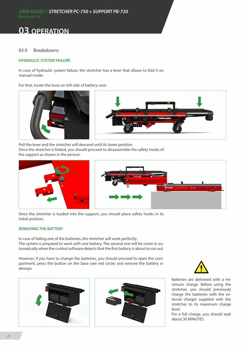
03.9 Breakdowns
HYDRAULIC SYSTEM FAILURE
In case of hydraulic system failure, the stretcher has a lever that allows to fold it on manual mode.
For that, locate the lever on left side of battery case:
Pull the lever and the stretcher will descend until its lower position. Once the stretcher is folded, you should proceed to dissassemble the safety hooks of the support as shown in the picture:
Once the stretcher is loaded into the support, you should place safety hooks in its initial position.
REMOVING THE BATTERY
In case of failing one of the batteries, the stretcher will work perfectly.The system is prepared to work with one battery. The second one will be come in au-tomatically when the control software detects that the first battery is about to run out.
However, if you have to change the batteries, you should proceed to open the com-partment, press the button on the base (see red circle) and remove the battery si-deways.
Batteries are delivered with a mi-nimum charge. Before using the stretcher, you should previously charge the batteries with the ex-ternal charger supplied with the stretcher to its maximum charge level.For a full charge, you should wait about 30 MINUTES.

USER GUIDE // STRETCHER PC-750 + SUPPORT PB-720Review 01/16
23
03.10 Troubleshooter
03 OPERATION
IMPORTANT CONSIDERATION
The electrical system of the stretcher will automatically turn off in 15 minutes if there are not make any operation. In manoeuvre of up and down repeatedly to 20 cycles continuosly, you should make a mandatory stop for at least 15 seconds for electro-hydraulic system of the stretcher recovers.
It is recommended to remove the two batteries of theirs anchors if the stretcher will spend long periods of inoperability. It is important to maintain a minimum of loading cycles every month to keep the good capacity of the batteries.
Not leave without charge the batteries more than 2 MONTHS. It is possible they will stop working.
COD. ERROR’S DESCRIPTION POSSIBLE CAUSE POSSIBLE SOLUTION
1
2
3
4
5
6
7
8
9
10
- VOLTAGE BATTERY IS LESS THAN 3V- THEY ARE DAMAGED OR DISCONNEC-TED
- VOLTAGE BATTERY IS LESS THAN 34V
- THE STRETCHER IS NOT RECEIVE VOLTA-GE FROM AMBULANCE
- VOLTAGE BATTERY IS LESS THAN 18V
- THE STRETCHER GETS THE VOLTAGE THROUGH TERMINAL CONNECTION OF THE SUPPORT, BUT THEY HAVE NOT BEEN PRESSED
- BATTERIES ARE NOT DETECTED
- FAIL IN THE DRIVER OF ENGINE
- INTENSITY ABOVE 48V
- VOLTAGE IS LESS THAN 15V
- FAIL IN CHARGING PROCESS
- BATTERIES DISCONNECTED- BATTERIES DAMAGED
- OVERCHARGE DURING THE CHARGING BATTERIES OV
- FAIL CONNECTION STRETCHER-SU-PPORT- AMBULANCE’S BATTERY DISCONNEC-TED OR DAMAGED- POWER CABLES WRONG WAY CONNEC-TED BETWEEN SUPPORT AND AMBULAN-CE - ONE OF TERMINALS COPPER OF THE STRETCHER
- BATTERIES ARE DISCONNECTED
- THE STRETCHER IS NOT PROPERLY ENTE-RED IN THE SUPPORT- FAIL IN MICROSWITCH
- BATTERIES DISCONNECTED- BATTERIES CONNECTION DAMAGED- BATTERIES CHARGE VERY LOW
- CONTACT WITH TECHNICAL SERVICE
- STRETCHER WITH OVERLOAD OF WEI-GHT- BATTERIES UNCHARGED- THE STRETCHER NOT UP/DOWN GENTLY
- STRETCHER WITH OVERLOAD OF WEI-GHT- BATTERIES UNCHARGED- THE STRETCHER NOT UP/DOWN GENTLY
- CONTACT WITH TECHNICAL SERVICE
- BATTERIES PROPERLY CONNECTING- CHECK CABLE CONNECTION BATTERIES WITH ELECTRIC PLATE- REPLACE BATTERIES
- COOL THE BATTERIES DURING 3/4 HOURS- USE THE CHARGER SUPPLIED BY PROMEBA- REPLACE BATTERIES FOR NEW ONES
- CHECK TERMINAL CONNECTION BETWEEN STRET-CHER-SUPPORT- CHARGE THE BATTERIES OR REPLACE FOR NEW ONES- CHECK THE CABLE CONNECTION BETWEEN STRET-CHER-SUPPORT-AMBULANCE- CHECK TERMINAL CONNECTION OF THE STRETCHER GOING INTO AND LEAVING THE ACCOMMODATION
- CHARGE BATTERIES UNTIL ITS MAXIMUM LEVEL
- ENSURE THE STRETCHER HAS ENTERED WELL INTO THE SUPPORT AND THE CONNECTION TERMINAL ARE WELL CONENCTED- CHECK THE STATUS OF MICROSWITCH
- ANCHOR WELL THE BATTERIES TO ITS BASE- REPLACE FOR NEW BATTERIES- CHARGE THEM WITH EXTERNAL PROMEBA’S CHARGER
- CONTACT WITH TECHNICAL SERVICE
- NOT LOAD THE STRETCHER WITH MORE THAN 300KG- CHARGE THEM WITH EXTERNAL PROMEBA’S CHARGER- SEARCH POSSIBLES SCRATCHS, INTERFERENCE OR LOC-KED PIECES IN THE STRETCHER
- NOT LOAD THE STRETCHER WITH MORE THAN 300KG- CHARGE THEM WITH EXTERNAL PROMEBA’S CHARGER- SEARCH POSSIBLES SCRATCHES, INTERFERENCE OR LOC-KED PIECES IN THE STRETCHER
- CONTACT WITH TECHNICAL SERVICE
USER GUIDE // STRETCHER PC-750 + SUPPORT PB-720Review 01/16
24
04 MOUNTING AND COMPONENTS
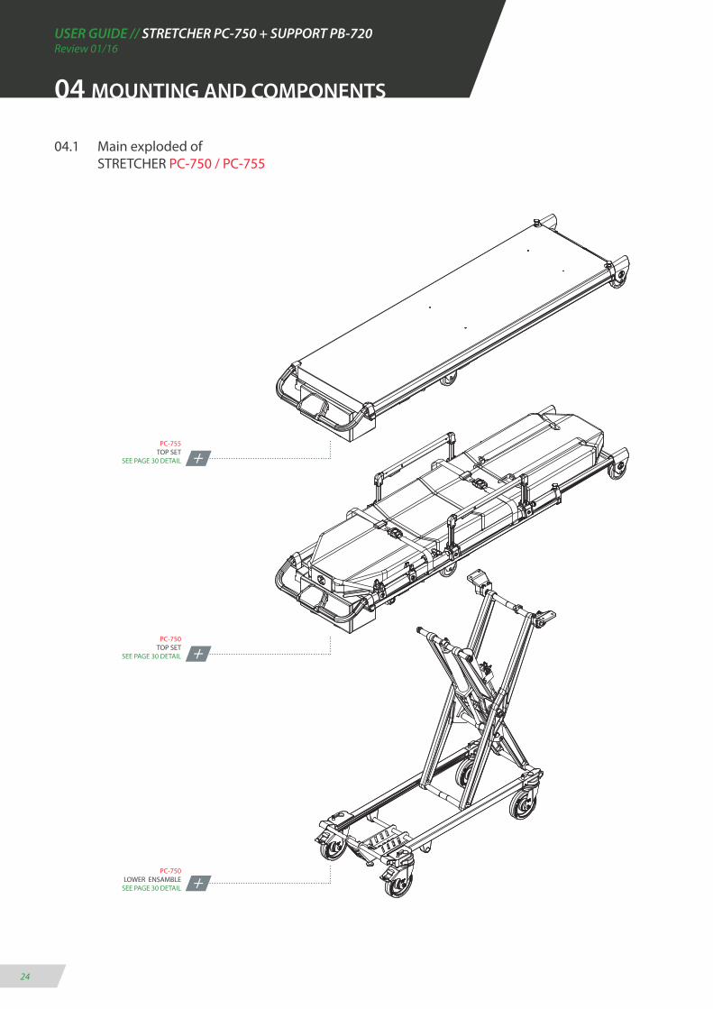
04.1 Main exploded of STRETCHER PC-750 / PC-755
PC-755TOP SET
SEE PAGE 30 DETAIL
PC-750TOP SET
SEE PAGE 30 DETAIL
PC-750LOWER ENSAMBLE
SEE PAGE 30 DETAIL
USER GUIDE // STRETCHER PC-750 + SUPPORT PB-720Review 01/16
25
04 MOUNTING AND COMPONENTS
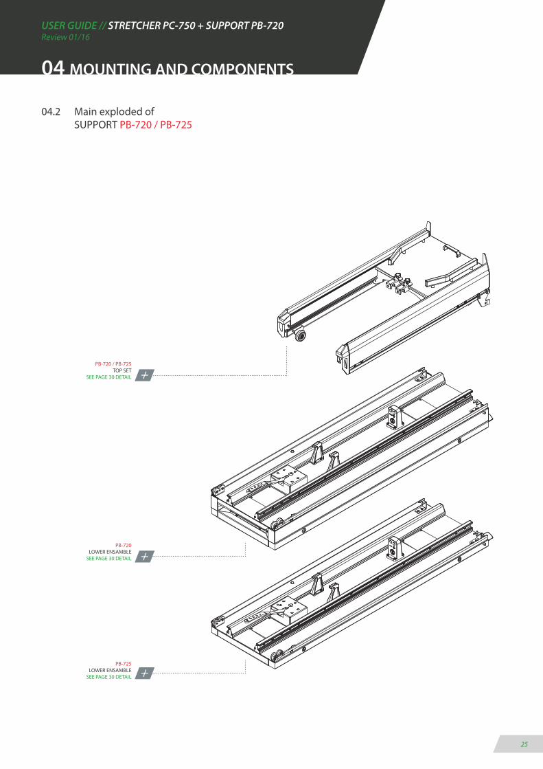
04.2 Main exploded of SUPPORT PB-720 / PB-725
PB-720 / PB-725TOP SET
SEE PAGE 30 DETAIL
PB-720LOWER ENSAMBLE
SEE PAGE 30 DETAIL
PB-725LOWER ENSAMBLE
SEE PAGE 30 DETAIL
USER GUIDE // STRETCHER PC-750 + SUPPORT PB-720Review 01/16
26
04 MOUNTING AND COMPONENTS
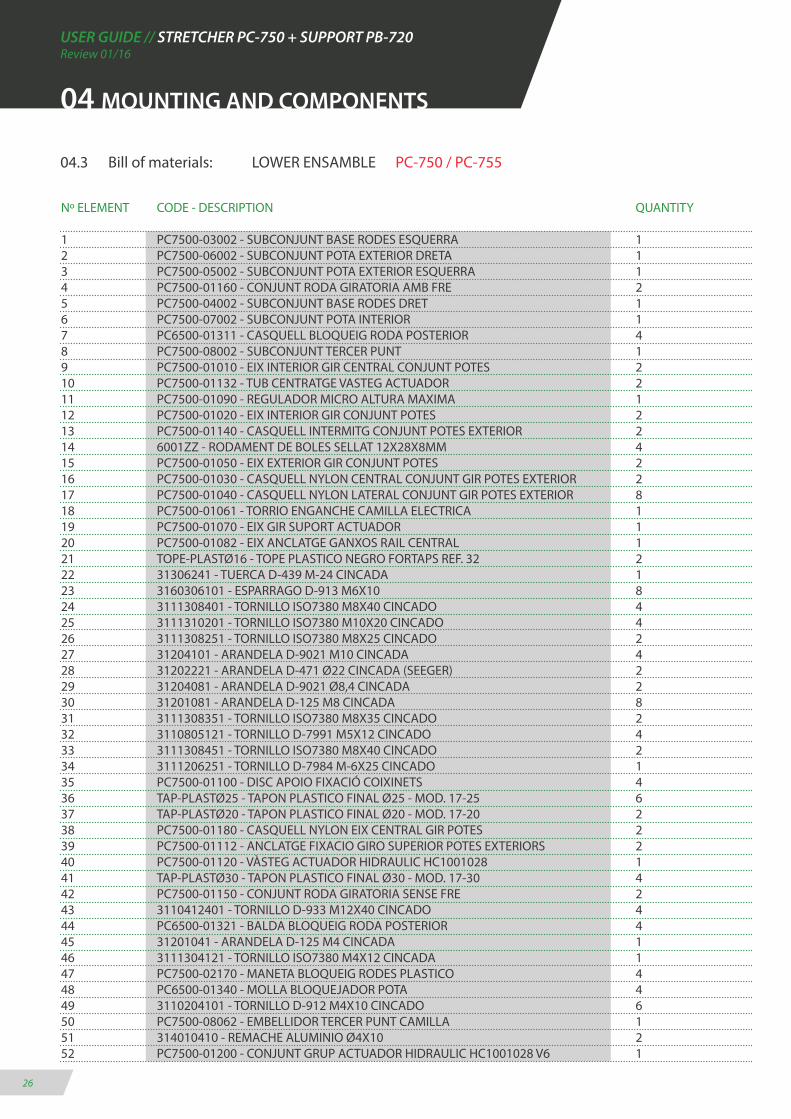
04.3 Bill of materials: LOWER ENSAMBLE PC-750 / PC-755
Nº ELEMENT CODE - DESCRIPTION QUANTITY
1 PC7500-03002 - SUBCONJUNT BASE RODES ESQUERRA 12 PC7500-06002 - SUBCONJUNT POTA EXTERIOR DRETA 13 PC7500-05002 - SUBCONJUNT POTA EXTERIOR ESQUERRA 14 PC7500-01160 - CONJUNT RODA GIRATORIA AMB FRE 25 PC7500-04002 - SUBCONJUNT BASE RODES DRET 16 PC7500-07002 - SUBCONJUNT POTA INTERIOR 17 PC6500-01311 - CASQUELL BLOQUEIG RODA POSTERIOR 48 PC7500-08002 - SUBCONJUNT TERCER PUNT 19 PC7500-01010 - EIX INTERIOR GIR CENTRAL CONJUNT POTES 210 PC7500-01132 - TUB CENTRATGE VASTEG ACTUADOR 211 PC7500-01090 - REGULADOR MICRO ALTURA MAXIMA 112 PC7500-01020 - EIX INTERIOR GIR CONJUNT POTES 213 PC7500-01140 - CASQUELL INTERMITG CONJUNT POTES EXTERIOR 214 6001ZZ - RODAMENT DE BOLES SELLAT 12X28X8MM 415 PC7500-01050 - EIX EXTERIOR GIR CONJUNT POTES 216 PC7500-01030 - CASQUELL NYLON CENTRAL CONJUNT GIR POTES EXTERIOR 217 PC7500-01040 - CASQUELL NYLON LATERAL CONJUNT GIR POTES EXTERIOR 818 PC7500-01061 - TORRIO ENGANCHE CAMILLA ELECTRICA 119 PC7500-01070 - EIX GIR SUPORT ACTUADOR 120 PC7500-01082 - EIX ANCLATGE GANXOS RAIL CENTRAL 121 TOPE-PLASTØ16 - TOPE PLASTICO NEGRO FORTAPS REF. 32 222 31306241 - TUERCA D-439 M-24 CINCADA 123 3160306101 - ESPARRAGO D-913 M6X10 824 3111308401 - TORNILLO ISO7380 M8X40 CINCADO 425 3111310201 - TORNILLO ISO7380 M10X20 CINCADO 426 3111308251 - TORNILLO ISO7380 M8X25 CINCADO 227 31204101 - ARANDELA D-9021 M10 CINCADA 428 31202221 - ARANDELA D-471 Ø22 CINCADA (SEEGER) 229 31204081 - ARANDELA D-9021 Ø8,4 CINCADA 230 31201081 - ARANDELA D-125 M8 CINCADA 831 3111308351 - TORNILLO ISO7380 M8X35 CINCADO 232 3110805121 - TORNILLO D-7991 M5X12 CINCADO 433 3111308451 - TORNILLO ISO7380 M8X40 CINCADO 234 3111206251 - TORNILLO D-7984 M-6X25 CINCADO 135 PC7500-01100 - DISC APOIO FIXACIÓ COIXINETS 436 TAP-PLASTØ25 - TAPON PLASTICO FINAL Ø25 - MOD. 17-25 637 TAP-PLASTØ20 - TAPON PLASTICO FINAL Ø20 - MOD. 17-20 238 PC7500-01180 - CASQUELL NYLON EIX CENTRAL GIR POTES 239 PC7500-01112 - ANCLATGE FIXACIO GIRO SUPERIOR POTES EXTERIORS 240 PC7500-01120 - VÀSTEG ACTUADOR HIDRAULIC HC1001028 141 TAP-PLASTØ30 - TAPON PLASTICO FINAL Ø30 - MOD. 17-30 442 PC7500-01150 - CONJUNT RODA GIRATORIA SENSE FRE 243 3110412401 - TORNILLO D-933 M12X40 CINCADO 444 PC6500-01321 - BALDA BLOQUEIG RODA POSTERIOR 445 31201041 - ARANDELA D-125 M4 CINCADA 146 3111304121 - TORNILLO ISO7380 M4X12 CINCADA 147 PC7500-02170 - MANETA BLOQUEIG RODES PLASTICO 448 PC6500-01340 - MOLLA BLOQUEJADOR POTA 449 3110204101 - TORNILLO D-912 M4X10 CINCADO 650 PC7500-08062 - EMBELLIDOR TERCER PUNT CAMILLA 151 314010410 - REMACHE ALUMINIO Ø4X10 252 PC7500-01200 - CONJUNT GRUP ACTUADOR HIDRAULIC HC1001028 V6 1
USER GUIDE // STRETCHER PC-750 + SUPPORT PB-720Review 01/16
27
04 MOUNTING AND COMPONENTS
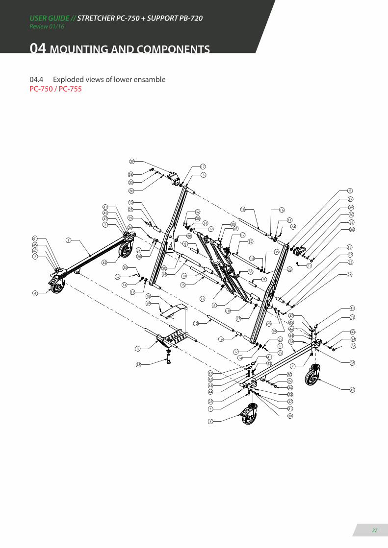
04.4 Exploded views of lower ensamble PC-750 / PC-755
48
2
17
39
30
3311
34
1615
3
1739
33
30
13
27
25
25
27
13
26
29
28
32
3514
17
17
12
14
35
32
9
38
10
17
17
15
1019
20
38
12
16
17
14
35
32
1
5
32
35
14
17
8
18
26
29
28
24
30
4
23
31
30
7
46
44
24
3044
23
237
42
21
6
36
37
36
36
36
41
4
42
47
41
45
7
9
41
23
45
7
41
43
43
50
47
47
45
47
45
46
47
49

USER GUIDE // STRETCHER PC-750 + SUPPORT PB-720Review 01/16
28
04 MOUNTING AND COMPONENTS
04.5 Bill of materials: UPPER ENSAMBLE PC-750
Nº ELEMENT CODE - DESCRIPTION QUANTITY
1 PC7500-11002 - CONJUNT GUIES SUPERIORS 22 PC7500-13012 - GUIA PASSACABLES GRUP ACTUADOR 13 PC7500-12000 - CONJUNT COMPARTIMENT BATERIES 14 PC7500-10000 - CONJUNT MARC CAPÇAL EXTENSIBLE 15 PC7500-15000 - CONJUNT BARANETA ABATIBLE ESQUERRA 16 PC7500-16000 - CONJUNT BARANETA ABATIBLE DRETA 17 PC6170-03470 - CONJUNT PORTASUERO UNIVERSAL 18 PC7500-09000 - CONJUNT CUADRE DE MANDOS 19 PC7500-14002 - SUBCONJUNT SUPORT CAPÇAL DE CARREGA 110 PC7500-17000 - CONJUNT CAPÇAL DE CARREGA CAMILLA 111 PC7500-18000 - CONJUNT LLITERA CAMILLA ELECTRICA PC-750 112 TECOX-7S-2D - CONJUNT FULLWATT LED REF. TECOX-7S-2D 213 PC7500-02012 - PERFIL SUPERIOR ALUMINI DRET 114 PC7500-02022 - PERFIL SUPERIOR ALUMINI ESQUERRA 115 GN 822-7-B-ST - POM POSICIONADOR SENSE BLOQUEIG 216 XCMD2102L3 - MICRO-RUPTOR AMB RODAMENT TELEMECANIQUE 117 PC6500-04081 - SOPORT CINTURONS 418 PC7500-02030 - TAP FINAL GUIA RODAMENT POTES 419 PC7500-02042 - TIRANT PERFILS INTERMITJOS 420 PC7500-02050 - SUPORT DAVANTER GIRO POTES EXTERIORS 221 PC7500-02062 - XAPA SUPORT PULSADOR TRENDELEMBURG 122 PC7500-02070 - FEMELLA SUBJECCIO PERFIL ALUMINI DRET 123 PC7500-02080 - FEMELLA SUBJECCIO PERFIL ALUMINI ESQUERRA 124 PB4100-02240 - DISC APOIO MOVIMENT LATERAL 225 PC7500-02092 - SUPORT RODA CONJUNT SUPERIOR CAMILLA 226 CD-RUEDA-100 - RODA PATÍ CAMILLA 100X24MM 227 PC7500-02122 - TERMINAL PERFIL SUPERIOR ESQUERRA 128 PC7500-02132 - TERMINAL PERFIL CAPÇAL RETRACTIL DRET 129 PC7500-02142 - TERMINAL PERFIL SUPERIOR DRET 130 PC7500-02152 - TERMINAL PERFIL CAPÇAL RETRACTIL ESQUERRA 131 TB-50342400-2GA - PULSADOR AWP DOBLE NEGRO-ROJO CABLE 750MM 132 PC7500-18150 - PASSACABLES ENDOLL DE CARGA LLARG 140CM 133 496379 - PASACABLES MOSS IP67 M20 134 COMP00867 - CASQUELL RODA 235 GN 611-M10-8-L - POSICIONADOR DE MUELLE M10 236 CONJUNT CINTURO ARNES ESQUERRA 137 CONJUNT CINTURO ARNES DRET 138 CONJUNT CINTURO LLENGUETA 239 CONJUNT CINTURO CIBELLA 240 31305061 - TUERCA D-985 M-6 CINCADA 541 31305081 - TUERCA D-985 M-8 CINCADA 2442 3111208251 - TORNILLO D-7984 M-8X25 CINCADO 1043 3110806601 - TORNILLO D-7991 M6X60 CINCADO 244 3111308451 - TORNILLO ISO7380 M8X45 CINCADO 245 3111308161 - TORNILLO ISO7380 M8X16 CINCADO 846 31201081 - ARANDELA D-125 M8 CINCADA 2847 3110408251 - TORNILLO D-933 M8X25 CINCADO 848 3111308351 - TORNILLO ISO7380 M8X35 CINCADO 249 3110408161 - TORNILLO D-933 M8X16 CINCADO 1250 3160305081 - ESPARREC D-914 M5X8 451 3111308401 - TORNILLO ISO7380 M8X40 CINCADO 2

USER GUIDE // STRETCHER PC-750 + SUPPORT PB-720Review 01/16
29
04 MOUNTING AND COMPONENTS
Nº ELEMENT CODE - DESCRIPTION QUANTITY
52 3111308251 - TORNILLO ISO7380 M8X25 CINCADO 253 31201061 - ARANDELA D-125 M6 CINCADA 954 3111306501 - TORNILLO ISO7380 M6X50 CINCADO 355 051329 - ARANDELA D-9021 M4 CINCADA 256 31305041 - TUERCA D-985 M-4 CINCADA 257 3111304301 - TORNILLO ISO7380 M4X30 CINCADO 258 3110808301 - TORNILLO D-7991 M8X30 CINCADO 459 31204061 - ARANDELA D-9021 M6 CINCADA 260 3110204101 - TORNILLO D-912 M4X10 CINCADO 461 3110905151 - TORNILLO DIN 7981 M5X15 CINCADO 362 PA-750 - MATALÀS TERMOSOLDAT ANATÒMIC 163 3111208301 - TORNILLO D-7984 M-8X30 CINCADO 864 T-LED3528 - TIRA ADHESIVA LED 12V-20W IP67 265 314010410 - REMACHE ALUMINIO Ø4X10 1266 31201062 - ARANDELA D-125 PARA M6 NYLON BLANCO 269 105-4-CATUB - CASQUILLO TUBO Ø14X7 270 31204081 - ARANDELA D-9021 Ø8,4 CINC ADA 271 3110208351 - TORNILLO D-7984 M-8X35 CINCADO 274 105-4-CATUB - CASQUILLO 14X7X3 CINCADO 275 04160180-551 - CADENA CABLE ACTUADOR E2 MICRO S04 L551MM 176 3111208351 - TORNILLO D-7984 M-8X35 CINCADO 277 3140410 - REMACHE ALUMINIO Ø4X10 2

USER GUIDE // STRETCHER PC-750 + SUPPORT PB-720Review 01/16
31
7775
17
39
17
39
36
62
11
4
3015
48
28
71
44
45
25
26
4123
27
8
29
45
76
19
4143
22
3160
45
21
24
20
19
12
6
32
9
10
16
54
59
66
57
3
1435
35
40
1
53
53
61
42
59
40
4174
46
6342
49
19
37
50
12
64
65
12
19
18
41
2
41
46
69
70
155
38 17
38
47
17
7
04 MOUNTING AND COMPONENTS
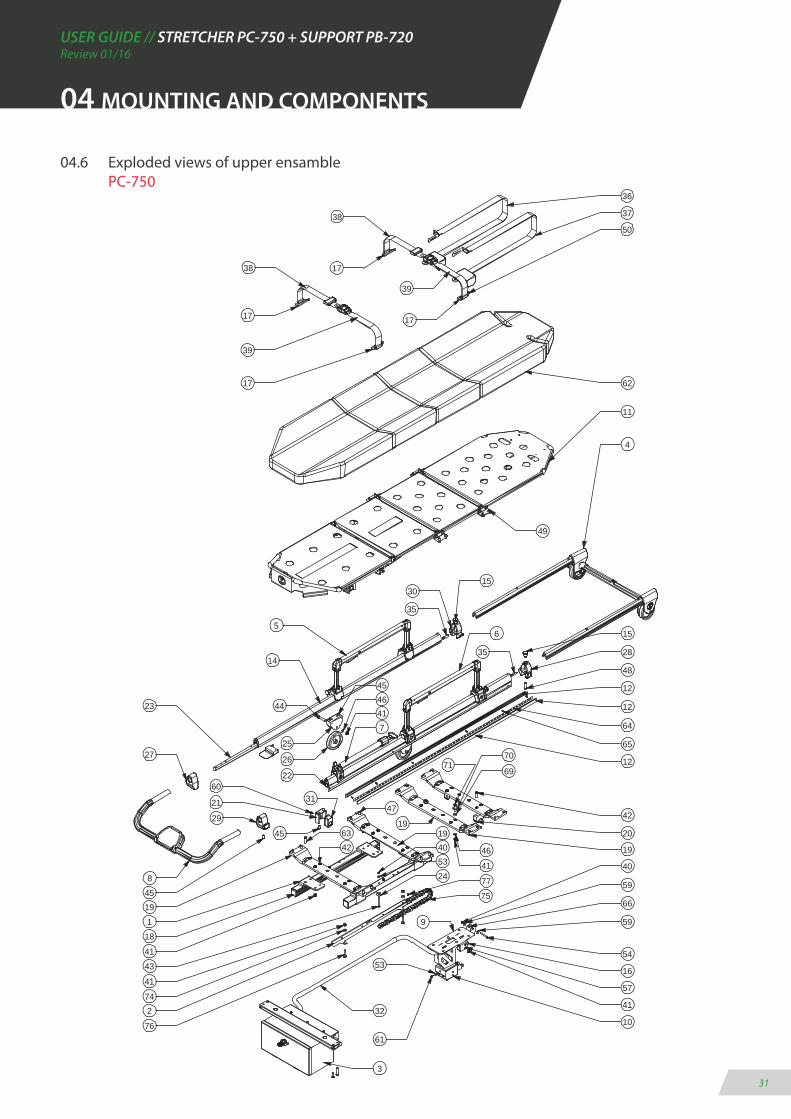
04.6 Exploded views of upper ensamble PC-750

USER GUIDE // STRETCHER PC-750 + SUPPORT PB-720Review 01/16
32
04 MOUNTING AND COMPONENTS
Nº ELEMENT CODE - DESCRIPTION QUANTITY
1 PC7500-11002 - CONJUNT GUIES SUPERIORS 22 PC7500-12000 - CONJUNT COMPARTIMENT BATERIES 13 PC7500-10000 - CONJUNT MARC CAPÇAL EXTENSIBLE 14 PC7500-09000 - CONJUNT CUADRE DE MANDOS 15 PC7500-14002 - SUBCONJUNT SUPORT CAPÇAL DE CARREGA 16 PC7500-17000 - CONJUNT CAPÇAL DE CARREGA CAMILLA 17 PC7550-03000 - CONJUNT INCUBADORA FULLWATT LED 28 PC7550-02012 - PERFIL SUPERIOR ALUMINI DRET INCUBADORA 19 PC7550-02022 - PERFIL SUPERIOR ALUMINI ESQUERRA INCUBADORA 110 GN 822-7-B-ST - POM POSICIONADOR SENSE BLOQUEIG 211 XCMD2102L3 - MICRO-RUPTOR AMB RODAMENT TELEMECANIQUE 112 PC7500-02030 - TAP FINAL GUIA RODAMENT POTES 413 PC7500-02042 - TIRANT PERFILS INTERMITJOS 414 PC7500-02050 - SUPORT DAVANTER GIRO POTES EXTERIORS 215 PC7550-02070 - FEMELLA SUBJECCIO PERFIL ALUMINI INCUBADORA 216 PB4100-02240 - DISC APOIO MOVIMENT LATERAL 217 PC7500-02092 - SUPORT RODA CONJUNT SUPERIOR CAMILLA 218 CD-RUEDA-100 - RODA PATÍ CAMILLA 100X24MM 219 PC7500-02122 - TERMINAL PERFIL SUPERIOR ESQUERRA 120 PC7500-02132 - TERMINAL PERFIL CAPÇAL RETRACTIL DRET 121 PC7500-02142 - TERMINAL PERFIL SUPERIOR DRET 122 PC7500-02152 - TERMINAL PERFIL CAPÇAL RETRACTIL ESQUERRA 123 PC7500-18150 - PASSACABLES ENDOLL DE CARGA LLARG 140CM 124 496379 - PASACABLES MOSS IP67 M20 125 PC7500-13012 - GUIA PASSACABLES GRUP ACTUADOR 126 COMP00867 - CASQUELL RODA 227 105-4-CATUB - CASQUILLO 14X7X3 CINCADO 228 04160180-551 - CADENA CABLE ACTUADOR E2 MICRO S04 L551MM 129 T-LED3529 - TIRA ADHESIVA LED 12V-20W IP67 230 PC7550-02030 - SAFATA CAMILLA INCUBADORA 131 PC7550-02042 - SUPORT SAFATA CAMILLA INCUBADORA 232 3111208351 - TORNILLO D-7984 M-8X35 CINCADO 233 31305081 - TUERCA D-985 M-8 CINCADO 2234 3111208251 - TORNILLO D-7984 M-8X25 CINCADO 1035 3110806601 - TORNILLO D-7991 M6X60 CINCADO 236 3111308451 - TORNILLO ISO7380 M8X45 CINCADO 237 31201081 - ARANDELA D-125 M8 CINCADO 2638 3110408251 - TORNILLO D-933 M8X25 CINCADO 2039 3111308161 - TORNILLO ISO7380 M8X16 CINCADO 640 3111308351 - TORNILLO ISO7380 M8X35 CINCADO 241 3111308401 - TORNILLO ISO7380 M8X40 CINCADO 242 3111308251 - TORNILLO ISO7380 M8X25 CINCADO 243 31201061 - ARANDELA D-125 M6 CINC ADO 644 31305061 - TUERCA D-985 M-6 CINC ADA 245 051329 - ARANDELA D-9021 M4 CINCADA 246 31305041 - TUERCA D-985 M-4 CINCADA 247 3111304301 - TORNILLO ISO7380 M4X30 CINCADO 248 3110808301 - TORNILLO D-7991 M8X30 CINCADO 449 3111208301 - TORNILLO D-7984 M-8X30 CINCADO 850 3110905151 - TORNILLO DIN 7981 M5X15 CINCADO 351 314010410 - REMACHE ALUMINIO Ø4X10 1855 GN 611-M10-8-L - POSICIONADOR DE MUELLE M10 2
04.7 Bill of materials: UPPER ENSAMBLE PC-755
USER GUIDE // STRETCHER PC-750 + SUPPORT PB-720Review 01/16
33
04 MOUNTING AND COMPONENTS
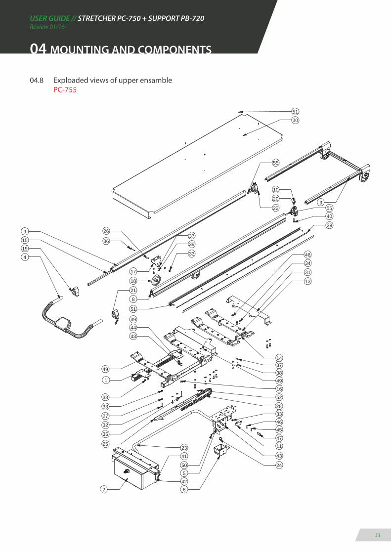
04.8 Exploaded views of upper ensamble PC-755
51
55
15
51
30
322
10
20
40
29
4834
31
27
14
38
47
46
11
43
24
6
550
28
35
41
422
23
32
44
25
1
49
21
4
8
19
13
9
18
17
36
26
39
37
39
33
49
55
16
45
33
33
43
37
33
52
USER GUIDE // STRETCHER PC-750 + SUPPORT PB-720Review 01/16
34
04 MOUNTING AND COMPONENTS
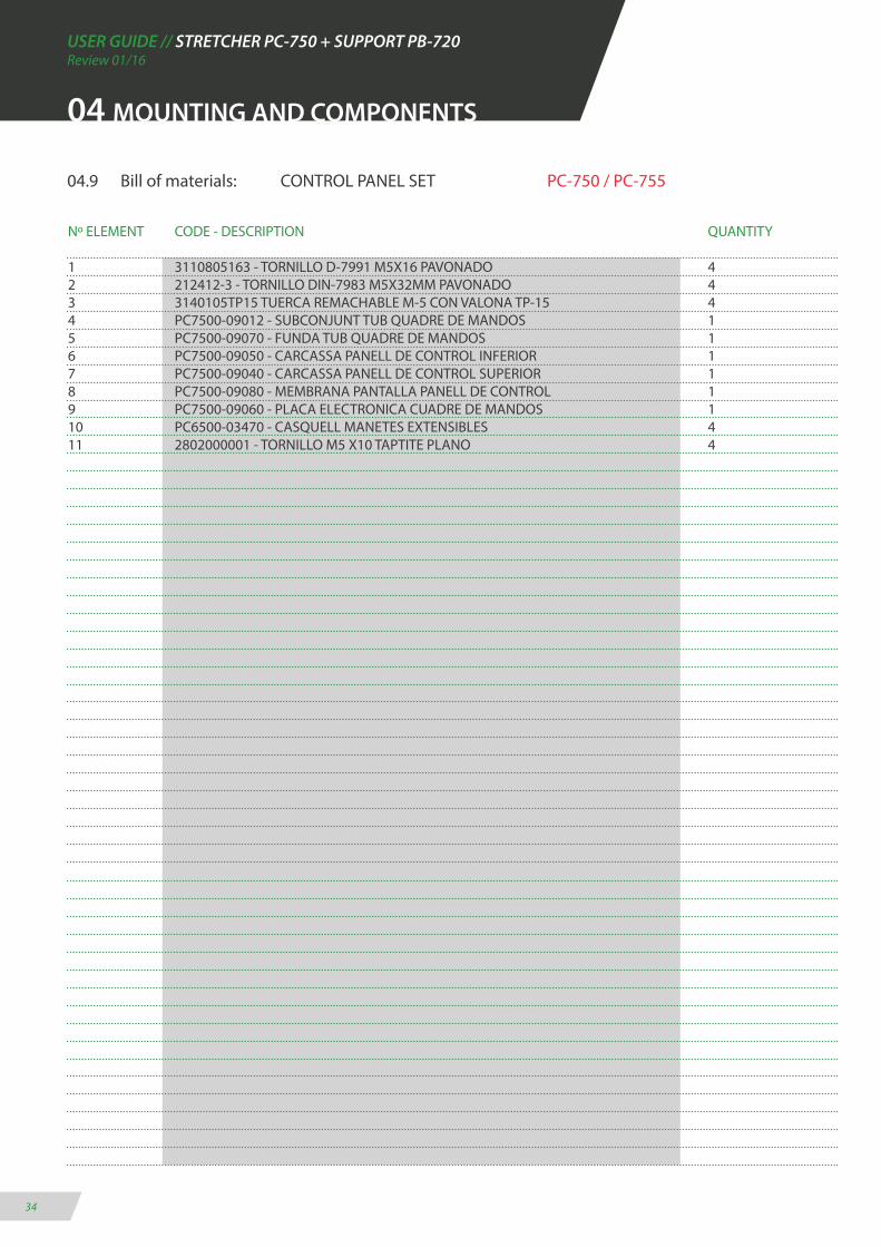
04.9 Bill of materials: CONTROL PANEL SET PC-750 / PC-755
Nº ELEMENT CODE - DESCRIPTION QUANTITY
1 3110805163 - TORNILLO D-7991 M5X16 PAVONADO 42 212412-3 - TORNILLO DIN-7983 M5X32MM PAVONADO 43 3140105TP15 TUERCA REMACHABLE M-5 CON VALONA TP-15 44 PC7500-09012 - SUBCONJUNT TUB QUADRE DE MANDOS 15 PC7500-09070 - FUNDA TUB QUADRE DE MANDOS 16 PC7500-09050 - CARCASSA PANELL DE CONTROL INFERIOR 17 PC7500-09040 - CARCASSA PANELL DE CONTROL SUPERIOR 18 PC7500-09080 - MEMBRANA PANTALLA PANELL DE CONTROL 19 PC7500-09060 - PLACA ELECTRONICA CUADRE DE MANDOS 110 PC6500-03470 - CASQUELL MANETES EXTENSIBLES 411 2802000001 - TORNILLO M5 X10 TAPTITE PLANO 4

USER GUIDE // STRETCHER PC-750 + SUPPORT PB-720Review 01/16
35
04 MOUNTING AND COMPONENTS
04.10 Exploaded views CONTROL PANEL SET PC-750 / PC-755
2
8
7
9
10
11
4
3
6
1 5
USER GUIDE // STRETCHER PC-750 + SUPPORT PB-720Review 01/16
36
04 MOUNTING AND COMPONENTS
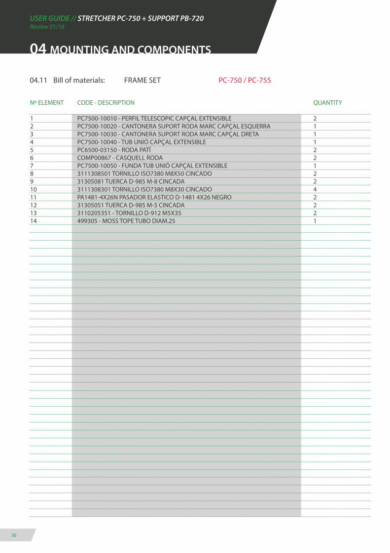
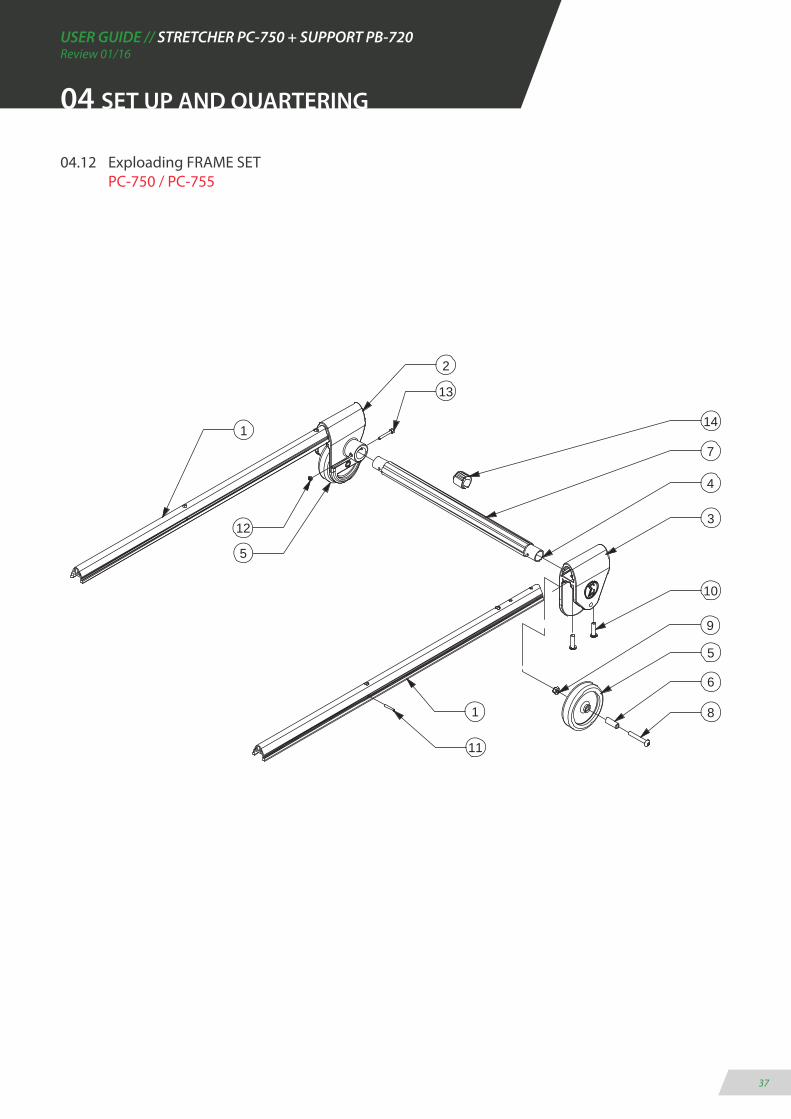
04.11 Bill of materials: FRAME SET PC-750 / PC-755
Nº ELEMENT CODE - DESCRIPTION QUANTITY
1 PC7500-10010 - PERFIL TELESCOPIC CAPÇAL EXTENSIBLE 22 PC7500-10020 - CANTONERA SUPORT RODA MARC CAPÇAL ESQUERRA 13 PC7500-10030 - CANTONERA SUPORT RODA MARC CAPÇAL DRETA 14 PC7500-10040 - TUB UNIÓ CAPÇAL EXTENSIBLE 15 PC6500-03150 - RODA PATÍ 26 COMP00867 - CASQUELL RODA 27 PC7500-10050 - FUNDA TUB UNIÓ CAPÇAL EXTENSIBLE 18 3111308501 TORNILLO ISO7380 M8X50 CINCADO 29 31305081 TUERCA D-985 M-8 CINCADA 210 3111308301 TORNILLO ISO7380 M8X30 CINCADO 411 PA1481-4X26N PASADOR ELASTICO D-1481 4X26 NEGRO 212 31305051 TUERCA D-985 M-5 CINCADA 213 3110205351 - TORNILLO D-912 M5X35 214 499305 - MOSS TOPE TUBO DIAM.25 1
USER GUIDE // STRETCHER PC-750 + SUPPORT PB-720Review 01/16
37
04.12 Exploading FRAME SET PC-750 / PC-755
9
13
6
2
81
4
7
312
5
1
11
10
5
14
04 SET UP AND QUARTERING

USER GUIDE // STRETCHER PC-750 + SUPPORT PB-720Review 01/16
38
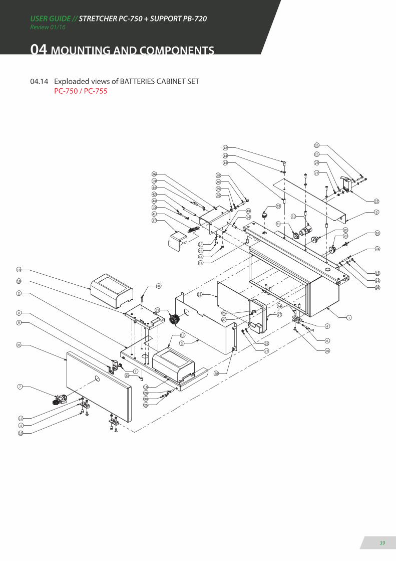
04.13 Bill of materials: BATTERIES CABINET SET PC-750 / PC-755
Nº ELEMENT CODE - DESCRIPTION QUANTITY
1 PC7500-12012 - SUBCONJUNT CAIXA COMPARTIMENT BATERIES 12 PC7500-12062 - SAFATA ANCLATGE BATERIES 13 PC7500-12072 - SAFATA PLACA ELECTRICA 14 1056-U30 - BISAGRA ARMARI EMKA REF. 1056-U30 45 PC7500-12092 - SUPORT MICRO FINAL DE CARRERA 16 1056-U30 - EIX BISAGRA ARMARI EMKA REF. 1056-U30 27 1500-U347 - PANY CUART DE VOLTA AMB PALOMETA REF. 1500-U347 18 1000-386-18 - PASTELL PANY CUART DE VOLTA REF. 1000-386-18 19 1500-05-15- EMKA CLIP REF. 1500-05-15 110 3110805121 - TORNILLO D-7991 M5X12 CINCADO 811 31305051 TUERCA D-985 M-5 CINCADA 412 3111305151 TORNILLO ISO7380 M5X15 CINCADO 713 31201051 ARANDELA D-125 M5 CINCADA 914 314020501 - TUERCA REMACHABLE M-5 CIEGA GRAF SIN VALONA 1115 PC7500-12040 - PLACA DE CONTROL PRINCIPAL PC-750 116 CRLCBSRE-4-01BK - SEPARADOR PCB H6.4 417 PC7500-12110 - VARIADOR MOTOR PC-750 118 PC7500-02100 - BATERIA ENERGIVM 2500 MAH - 25.6V 219 PC7500-02110 - ADAPTADOR BATERIA ENERGIVM 220 496379 - PASACABLES MOSS IP67 M20 221 494612 - TERMINAL CONDUCTO PASACABLES DIAM.20 122 XCMD2110L1 - MICRO-RUPTOR AMB PULSADOR TELEMECANIQUE 123 TAP-PLASTØ20 - TAPON PLASTICO FINAL Ø20 - MOD. 17-20 224 3111304351 TORNILLO ISO7380 M4X35 CINCADO 225 31201041 - ARANDELA D-125 M4 CINCADA 826 051329 - ARANDELA D-9021 M4 CINCADA 227 31305041 - TUERCA D-985 M-4 CINCADA 428 3140105TPB15 - TUERCA REMACHABLE M-5 CON VALONA TPB-15 429 3140104TPB15 - TUERCA REMACHABLE M-4 CON VALONA TPB-15 230 3111304121 - TORNILLO ISO7380 M4X12 CINCADA 231 PC7500-12120 - SUBCONJUNT PORTA COMPARTIMENT BATERIES 132 PC7500-12130 - MINIZUMBADOR INT SEE-2071 6-24V CC 133 314020412 - TUERCA REMACHABLE M-4 GRAF SIN VALONA 1234 3110204201 - TORNILLO D-912 M4X20 CINCADO 1235 3110204251 - TORNILLO D-912 M4X25 CINCADO 236 PC7500-12142 - SUPORT U PULSADOR SEGURETAT 137 PC7500-12102 - PALANCA PULSADOR SEGURETAT 138 PB4010-00060 - TERMINAL FUNDA CABLES T01-05 139 31301071 - TUERCA D-934 M-7 CINCADA 240 PB4010-00040 - TENSOR UNIVERSAL 141 PB4400-03130 - MOLLA GANXOS 142 317010660 - PERNO CON RANURA 6X60 CINCADO 143 31207051 - ARANDELA D-6799 PARA Ø5 CINCADA 144 3110205151 - TORNILLO D-912 M5X15 CINCADO 4
04 MOUNTING AND COMPONENTS
USER GUIDE // STRETCHER PC-750 + SUPPORT PB-720Review 01/16
39
04.14 Exploaded views of BATTERIES CABINET SET PC-750 / PC-755
18
36
10
13
31
7
25
4
11
8
7
9
27
30
2
19
18
29
3
28
25
27
17
15
27
251
6
4
10
14
12
13
25
24
1620
23
20
14
39
44
41
37
44
35
22
26
12
5
13
21
21
32
34
33
25
19
14
39
43
44
44
1338
14
40
42
14
04 MOUNTING AND COMPONENTS

USER GUIDE // STRETCHER PC-750 + SUPPORT PB-720Review 01/16
40
04.15 Bill of materials: LEFT HANDRAIL ENSAMBLE PC-750
Nº ELEMENT CODE - DESCRIPTION QUANTITY
1 PC6501-04040 - SUPORT ACCIONAMENT 12 PC6501-04170 - CASQUELL SEPARADOR L30 23 PC6501-04112 - TUB OVAL BARANETA 14 PC6501-04160 - GATELL I MANETA ACCIOMANENT BARANETA 15 PC6501-04140 - MOLLA GATELL BARANETA 16 PC6501-04100 - SUPORT ARRASTRE 17 PC6501-04090 - CASQUELL SEPARADOR L25 28 PC6501-04080 - CASQUELL SEPARADOR L18 19 PA1481-3X20N - PASADOR ELASTICO D-1481 3X20 NEGRO 210 PA1481-4X10N - PASADOR ELASTICO D-1481 4X10 NEGRO 111 2802000001 - TORNILLO M5 X10 TAPTITE PLANO 612 3110204251 - TORNILLO D-912 M4X25 CINCADO 213 3131305101 - TORNILLO ISO7380 M5X10 CINCADO 414 31201061 - ARANDELA D-125 M6 CINCADA 415 PC7500-15022 - SUPORT FIXACIÓ BARANA 216 317010660 - PERNO CON RANURA 6X60 CINCADO 217 GN 822-7-B-ST - POM POSICIONADOR SENSE BLOQUEIG 218 PC6501-04150A - CANTONERA BARANETA TUB OVAL 219 PC6501-04020 - MANETA ACCIONAMENT BARANETA 120 3160305081 - ESPARREC D-914 M5X8 421 31207051 - ARANDELA D-6799 PARA Ø5 CINCADA 222 PC7500-15012 - SUPORT FIXACIÓ BARANA ABATIBLE ESQUERRA 223 461241 - POTA AUTOADHESIVA 19X1.9MM 2
04 MOUNTING AND COMPONENTS

USER GUIDE // STRETCHER PC-750 + SUPPORT PB-720Review 01/16
41
04.16 Exploaded views of LEFT HANDRAIL ENSAMBLE PC-750
04 MOUNTING AND COMPONENTS
11
23
3
18
11
17
19
20
16
22
13
14
6
22
17
15
18
11
14
13
16
20
15
1
5
4
11
9
10
8
117
12
12
13
14
2
21
2
23
USER GUIDE // STRETCHER PC-750 + SUPPORT PB-720Review 01/16
42
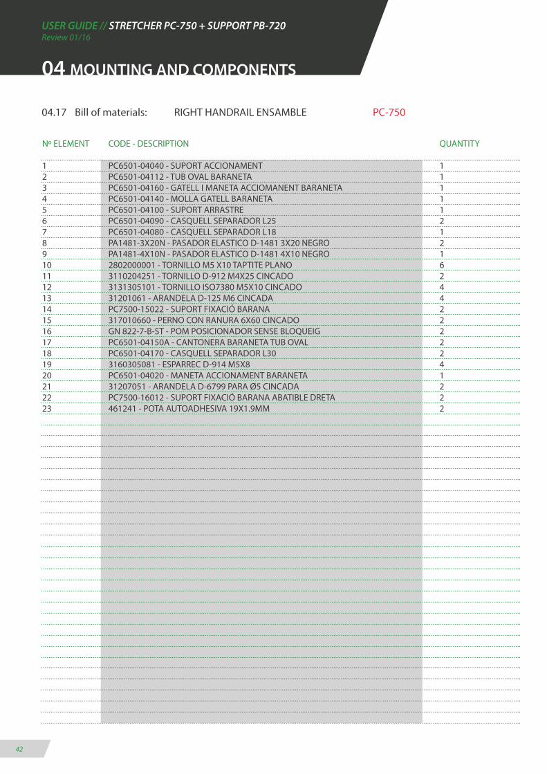
04.17 Bill of materials: RIGHT HANDRAIL ENSAMBLE PC-750
Nº ELEMENT CODE - DESCRIPTION QUANTITY
1 PC6501-04040 - SUPORT ACCIONAMENT 12 PC6501-04112 - TUB OVAL BARANETA 13 PC6501-04160 - GATELL I MANETA ACCIOMANENT BARANETA 14 PC6501-04140 - MOLLA GATELL BARANETA 15 PC6501-04100 - SUPORT ARRASTRE 16 PC6501-04090 - CASQUELL SEPARADOR L25 27 PC6501-04080 - CASQUELL SEPARADOR L18 18 PA1481-3X20N - PASADOR ELASTICO D-1481 3X20 NEGRO 29 PA1481-4X10N - PASADOR ELASTICO D-1481 4X10 NEGRO 110 2802000001 - TORNILLO M5 X10 TAPTITE PLANO 611 3110204251 - TORNILLO D-912 M4X25 CINCADO 212 3131305101 - TORNILLO ISO7380 M5X10 CINCADO 413 31201061 - ARANDELA D-125 M6 CINCADA 414 PC7500-15022 - SUPORT FIXACIÓ BARANA 215 317010660 - PERNO CON RANURA 6X60 CINCADO 216 GN 822-7-B-ST - POM POSICIONADOR SENSE BLOQUEIG 217 PC6501-04150A - CANTONERA BARANETA TUB OVAL 218 PC6501-04170 - CASQUELL SEPARADOR L30 219 3160305081 - ESPARREC D-914 M5X8 420 PC6501-04020 - MANETA ACCIONAMENT BARANETA 121 31207051 - ARANDELA D-6799 PARA Ø5 CINCADA 222 PC7500-16012 - SUPORT FIXACIÓ BARANA ABATIBLE DRETA 223 461241 - POTA AUTOADHESIVA 19X1.9MM 2
04 MOUNTING AND COMPONENTS
USER GUIDE // STRETCHER PC-750 + SUPPORT PB-720Review 01/16
43
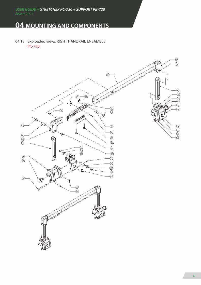
04.18 Exploaded views RIGHT HANDRAIL ENSAMBLE PC-750
04 MOUNTING AND COMPONENTS
13
1
10 23
10
11
11
20
9
10
7
8
4 10
2
17
10
5
18
16
1312
14
22
15
16
12
6
13
21
18
12
15
1422
19
19
3
1719
23
USER GUIDE // STRETCHER PC-750 + SUPPORT PB-720Review 01/16
44
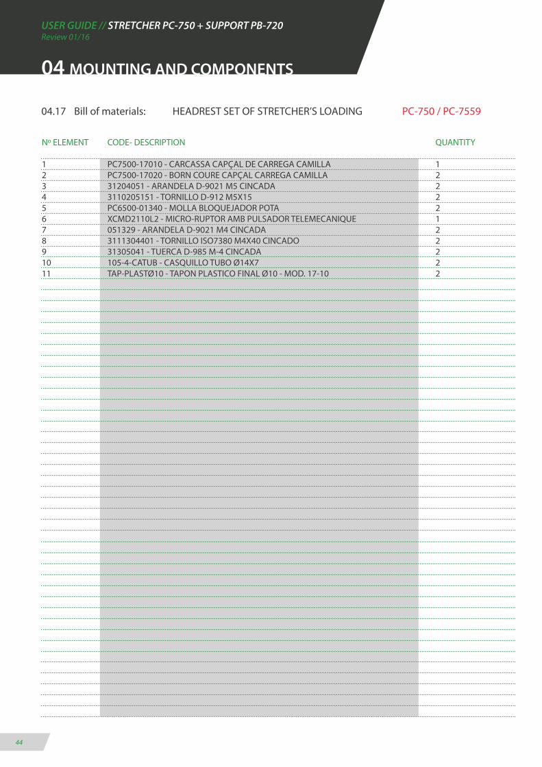
04.17 Bill of materials: HEADREST SET OF STRETCHER’S LOADING PC-750 / PC-7559
Nº ELEMENT CODE- DESCRIPTION QUANTITY
1 PC7500-17010 - CARCASSA CAPÇAL DE CARREGA CAMILLA 12 PC7500-17020 - BORN COURE CAPÇAL CARREGA CAMILLA 23 31204051 - ARANDELA D-9021 M5 CINCADA 24 3110205151 - TORNILLO D-912 M5X15 25 PC6500-01340 - MOLLA BLOQUEJADOR POTA 26 XCMD2110L2 - MICRO-RUPTOR AMB PULSADOR TELEMECANIQUE 17 051329 - ARANDELA D-9021 M4 CINCADA 28 3111304401 - TORNILLO ISO7380 M4X40 CINCADO 29 31305041 - TUERCA D-985 M-4 CINCADA 210 105-4-CATUB - CASQUILLO TUBO Ø14X7 211 TAP-PLASTØ10 - TAPON PLASTICO FINAL Ø10 - MOD. 17-10 2
04 MOUNTING AND COMPONENTS
USER GUIDE // STRETCHER PC-750 + SUPPORT PB-720Review 01/16
45
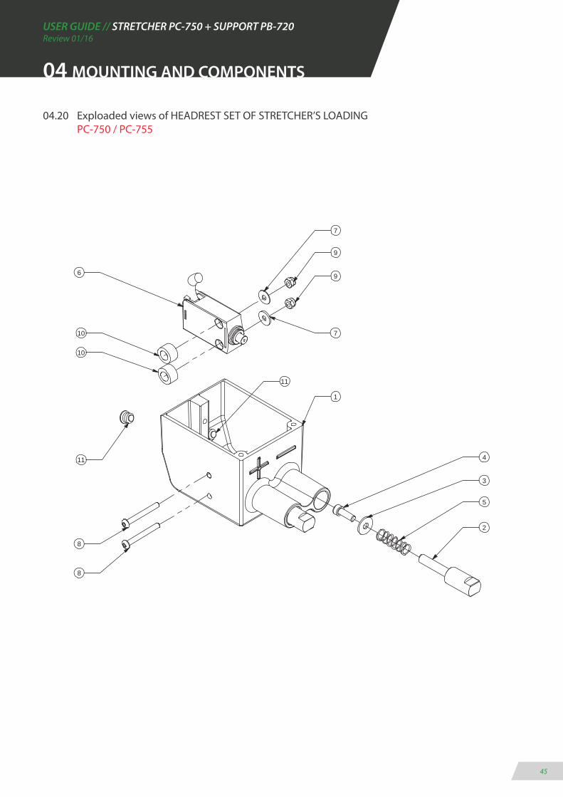
04.20 Exploaded views of HEADREST SET OF STRETCHER’S LOADING PC-750 / PC-755
04 MOUNTING AND COMPONENTS
7
7
9
9
11
2
5
3
4
8
8
11
10
10
6
1
USER GUIDE // STRETCHER PC-750 + SUPPORT PB-720Review 01/16
46
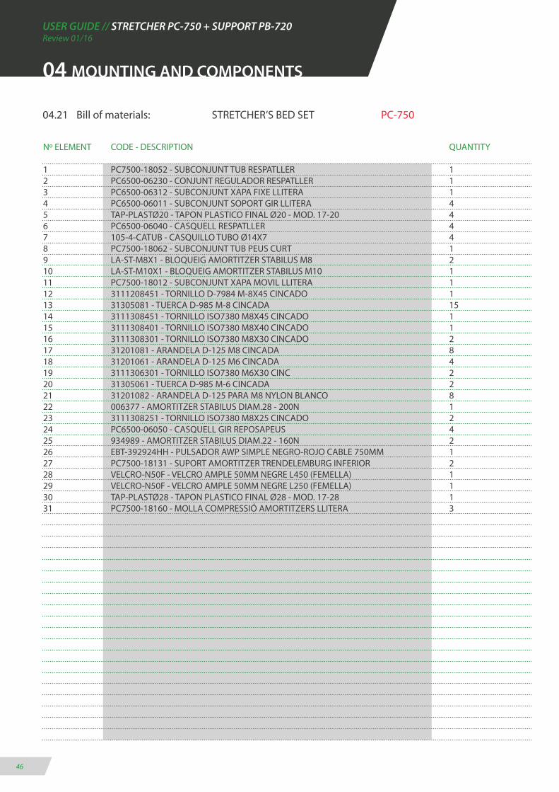
04.21 Bill of materials: STRETCHER’S BED SET PC-750
Nº ELEMENT CODE - DESCRIPTION QUANTITY
1 PC7500-18052 - SUBCONJUNT TUB RESPATLLER 12 PC6500-06230 - CONJUNT REGULADOR RESPATLLER 13 PC6500-06312 - SUBCONJUNT XAPA FIXE LLITERA 14 PC6500-06011 - SUBCONJUNT SOPORT GIR LLITERA 45 TAP-PLASTØ20 - TAPON PLASTICO FINAL Ø20 - MOD. 17-20 46 PC6500-06040 - CASQUELL RESPATLLER 47 105-4-CATUB - CASQUILLO TUBO Ø14X7 48 PC7500-18062 - SUBCONJUNT TUB PEUS CURT 19 LA-ST-M8X1 - BLOQUEIG AMORTITZER STABILUS M8 210 LA-ST-M10X1 - BLOQUEIG AMORTITZER STABILUS M10 111 PC7500-18012 - SUBCONJUNT XAPA MOVIL LLITERA 112 3111208451 - TORNILLO D-7984 M-8X45 CINCADO 113 31305081 - TUERCA D-985 M-8 CINCADA 1514 3111308451 - TORNILLO ISO7380 M8X45 CINCADO 115 3111308401 - TORNILLO ISO7380 M8X40 CINCADO 116 3111308301 - TORNILLO ISO7380 M8X30 CINCADO 217 31201081 - ARANDELA D-125 M8 CINCADA 818 31201061 - ARANDELA D-125 M6 CINCADA 419 3111306301 - TORNILLO ISO7380 M6X30 CINC 220 31305061 - TUERCA D-985 M-6 CINCADA 221 31201082 - ARANDELA D-125 PARA M8 NYLON BLANCO 822 006377 - AMORTITZER STABILUS DIAM.28 - 200N 123 3111308251 - TORNILLO ISO7380 M8X25 CINCADO 224 PC6500-06050 - CASQUELL GIR REPOSAPEUS 425 934989 - AMORTITZER STABILUS DIAM.22 - 160N 226 EBT-392924HH - PULSADOR AWP SIMPLE NEGRO-ROJO CABLE 750MM 127 PC7500-18131 - SUPORT AMORTITZER TRENDELEMBURG INFERIOR 228 VELCRO-N50F - VELCRO AMPLE 50MM NEGRE L450 (FEMELLA) 129 VELCRO-N50F - VELCRO AMPLE 50MM NEGRE L250 (FEMELLA) 130 TAP-PLASTØ28 - TAPON PLASTICO FINAL Ø28 - MOD. 17-28 131 PC7500-18160 - MOLLA COMPRESSIÓ AMORTITZERS LLITERA 3
04 MOUNTING AND COMPONENTS

USER GUIDE // STRETCHER PC-750 + SUPPORT PB-720Review 01/16
47
04.22 Exploaded views of STRETCHER’S BED SET PC-750
17
8
4
11
3
1
6
13
12
2
4
157
7
13
27
7
2420
18
25
13
21
21
23
22
10
16
2113
19
18
9
13
7 14
4
13
31
6
5
27
9
25
24
24
24
5
6
26
29
28
30
31
31
04 MOUNTING AND COMPONENTS
USER GUIDE // STRETCHER PC-750 + SUPPORT PB-720Review 01/16
48
04 MOUNTING AND COMPONENTS
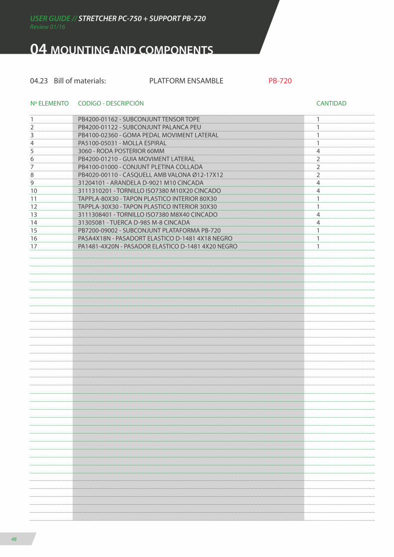
04.23 Bill of materials: PLATFORM ENSAMBLE PB-720
Nº ELEMENTO CODIGO - DESCRIPCIÓN CANTIDAD
1 PB4200-01162 - SUBCONJUNT TENSOR TOPE 12 PB4200-01122 - SUBCONJUNT PALANCA PEU 13 PB4100-02360 - GOMA PEDAL MOVIMENT LATERAL 14 PA5100-05031 - MOLLA ESPIRAL 15 3060 - RODA POSTERIOR 60MM 46 PB4200-01210 - GUIA MOVIMENT LATERAL 27 PB4100-01000 - CONJUNT PLETINA COLLADA 28 PB4020-00110 - CASQUELL AMB VALONA Ø12-17X12 29 31204101 - ARANDELA D-9021 M10 CINCADA 410 3111310201 - TORNILLO ISO7380 M10X20 CINCADO 411 TAPPLA-80X30 - TAPON PLASTICO INTERIOR 80X30 112 TAPPLA-30X30 - TAPON PLASTICO INTERIOR 30X30 113 3111308401 - TORNILLO ISO7380 M8X40 CINCADO 414 31305081 - TUERCA D-985 M-8 CINCADA 415 PB7200-09002 - SUBCONJUNT PLATAFORMA PB-720 116 PASA4X18N - PASADORT ELASTICO D-1481 4X18 NEGRO 117 PA1481-4X20N - PASADOR ELASTICO D-1481 4X20 NEGRO 1

USER GUIDE // STRETCHER PC-750 + SUPPORT PB-720Review 01/16
49
04 MOUNTING AND COMPONENTS
04.24 Exploaded views of PLATFORM ENSAMBLE PB-720
15
6
11
5
2
8
17
7
1
4
12
8
10
9
6
7
9
10
13
3
14
16

USER GUIDE // STRETCHER PC-750 + SUPPORT PB-720Review 01/16
50
04 MOUNTING AND COMPONENTS
04.25 Bill of materials: PLATFORM ENSAMBLE PB-725
Nº ELEMENT CODE - DESCRIPTION QUANTITY
1 PB4200-01122 - SUBCONJUNT PALANCA PEU 12 PB4100-02360 - GOMA PEDAL MOVIMENT LATERAL 13 3060 - RODA POSTERIOR 60MM 44 PB4200-01210 - GUIA MOVIMENT LATERAL 25 PB4100-01000 - CONJUNT PLETINA COLLADA 26 PB4020-00110 - CASQUELL AMB VALONA Ø12-17X12 27 TAPPLA-80X30 - TAPON PLASTICO INTERIOR 80X30 18 TAPPLA-30X30 - TAPON PLASTICO INTERIOR 30X30 19 3111308401 - TORNILLO ISO7380 M8X40 CINCADO 410 31305081- TUERCA D-985 M-8 CINCADA 411 PASA4X18N - PASADORT ELASTICO D-1481 4X18 NEGRO 112 PA1481-4X20N - PASADOR ELASTICO D-1481 4X20 NEGRO 113 PB7250-09002 - SUBCONJUNT PLATAFORMA PB-725 114 PB7250-01162 - SUBCONJUNT TENSOR TOPE 115 303-339 - MOLLA COMPRESSIÓ 55X13.75X2 216 PB4100-00291 - VALDA FIXACIO 217 PC6170-03291 - BRIDA SUBJECCIÓ BALDA 218 PB4010-00040 - TENSOR UNIVERSAL 219 PB7250-03011 - ARANDELA COLLADA EIX 420 PA1481-4X18N - PASADOR ELASTICO D-1481 4X18 NEGRO 221 3110204201 - TORNILLO D-912 M4X20 CINCADO 222 3110405101 - TORNILLO D-933 M5X10 CINCADO 423 31305041 - TUERCA D-985 M-4 CINCADA 224 31301071 - TUERCA D-934 M-7 CINCADA 425 3110810251 - TORNILLO D-7991 M10X25 CINCADO 4

USER GUIDE // STRETCHER PC-750 + SUPPORT PB-720Review 01/16
51
23
2
1
6
14
8
6
4
5
9
3
10
7
12
11
13
15
16
18
17
19
20
25
21
22
24
04 MOUNTING AND COMPONENTS
04.26 Exploaded views of PLATFORM ENSAMBLE PB-725

USER GUIDE // STRETCHER PC-750 + SUPPORT PB-720Review 01/16
52
04 MOUNTING AND COMPONENTS
04.27 Bill of materials: SUPPLEMENT ENSAMBLE PB-720
Nº ELEMENT CODE - DESCRIPTION QUANTITY
1 PB4100-04420 - BRIDA SUBJECCIO PALES 22 PB4200-02112 - XAPA TOPE CAMILLA 23 PB4200-02090 - CASQUELL SOPORT CAMILLA 24 PB4200-02082 - U TOPE PALAS 15 496379 - PASACABLES MOSS IP67 M20 16 PB4100-00291 - VALDA FIXACIO 27 PA1481-4X18N - PASADOR ELASTICO D-1481 4X18 NEGRO 28 PC6170-03291 - BRIDA SUBJECCIÓ BALDA 29 303-339 - MOLLA COMPRESSIÓ 55X13.75X2 110 PB4010-00040 - TENSOR UNIVERSAL 211 TAPPLA100X60 - TAPON PLASTICO INTERIOR 100X60 412 3111206251 - TORNILLO D-7984 M-6X25 CINCADO 213 31305061 - TUERCA D-985 M-6 CINCADA 414 3110806401 - TORNILLO D-7991 M6X40 CINCADO 215 3140200600 - TUERCA REMACHABLE M-6 GRAF SIN VALONA 416 314020801 - TUERCA REMACHABLE M-8 GRAF SIN VALONA 417 31201081 - ARANDELA D-125 M8 CINCADA 118 3110204201 - TORNILLO D-912 M4X20 CINCADO 219 31305041 - TUERCA D-985 M-4 CINCADA 220 3110405101 - TORNILLO D-933 M5X10 CINCADO 421 31301071 - TUERCA D-934 M-7 CINCADA 422 31201101 - ARANDELA D-125 PARA M10 CINCADA 223 3110210301 - TORNILLO D-912 M-10X30 CINCADO 224 31305101 - TUERCA D-985 M-10 CINCADA 225 PB7200-04010 - RAMPA CONJUNT SUPLEMENT PB-720 126 PB7200-08002 - SUBCONJUNT SUPLEMENT PB-720 127 3111306161 - TORNILLO ISO-7380 M6X16 CINCADO 228 31201061 - ARANDELA D-125 M6 CINCADA 329 3111306101 - TORNILLO ISO-7380 M6X10 CINCADO 3
USER GUIDE // STRETCHER PC-750 + SUPPORT PB-720Review 01/16
53
04 MOUNTING AND COMPONENTS
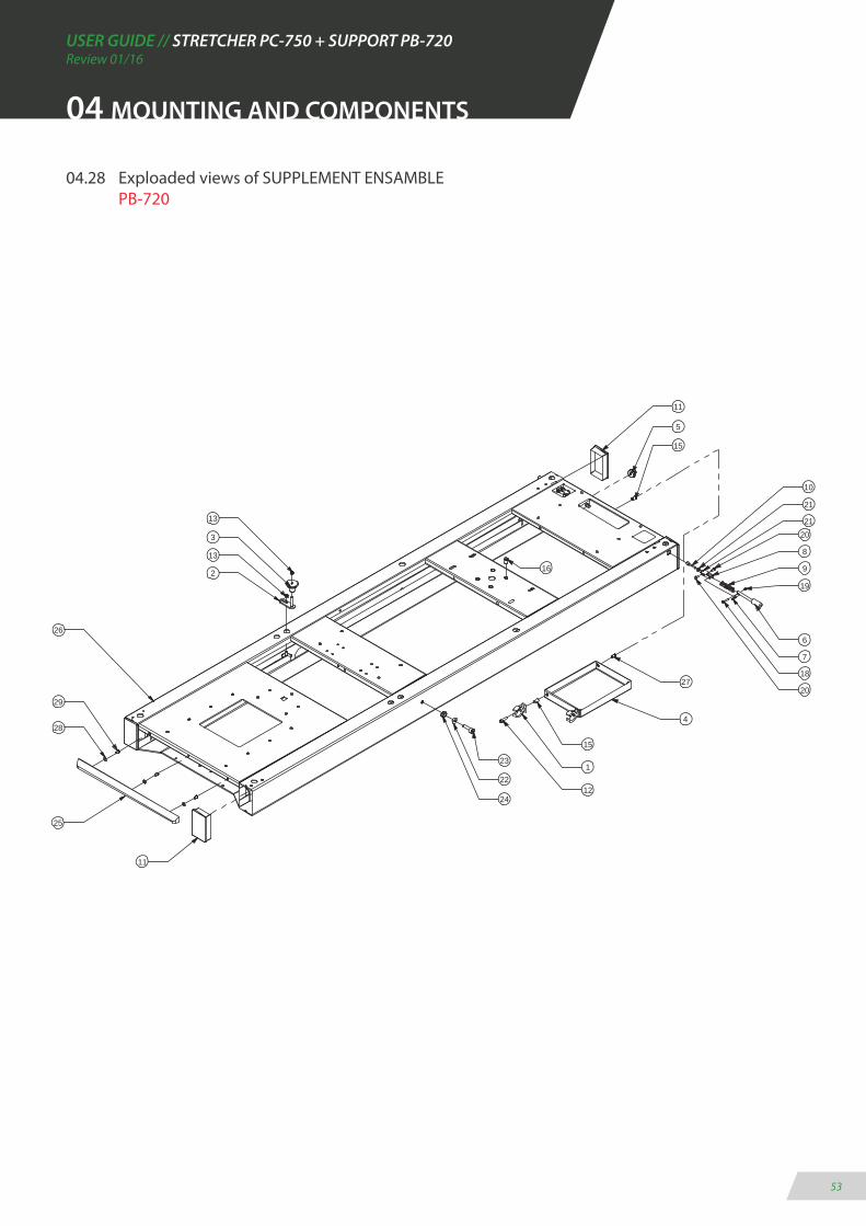
04.28 Exploaded views of SUPPLEMENT ENSAMBLE PB-720
20
11
5
15
6
7
18
19
9
8
20
28
21
21
10
27
4
15
1
12
23
22
24
11
26
13
3
13
2 16
25
29

USER GUIDE // STRETCHER PC-750 + SUPPORT PB-720Review 01/16
54
04 MOUNTING AND COMPONENTS
04.29 Bill of materials: FIXED SUPPORT STRETCHER SYSTEM PB-720
Nº ELEMENT CODE - DESCRIPTION QUANTITY
1 PB7200-03000 - CONJUNT PLATAFORMA PB-720 12 PB7200-04000 - CONJUNT SUPLEMENT PB-720 13 PB7200-10000 - CONJUNT CAPÇAL DE CARREGA PB-720 14 PB7200-11000 - CONJUNT TENCA TERCER PUNT PB-720 15 PC6500-05100 - CINTA SUBJECCIÓ TAULA 1MT 16 PB7200-02010 - SAFATA INOX RAIL PB-720 17 PC2100-04012 - PASSAMA 14X4 28 PB7200-02022 - GANXO CENTRAL RAIL 29 PB7200-02030 - PERFIL EXTERIOR GUIA RAIL 210 PB7200-02040 - TAPA PERFIL EXTERIOR GUIA DRETA 211 PB7200-02140 - TAPA PERFIL EXTERIOR GUIA ESQUERRA 212 496379 - PASACABLES MOSS IP67 M20 113 PB7200-02052 - GANXO POSTERIOR SUPLETORI DAVANTER 214 PB7200-02060 - JUNTA GOMA PERFIL EXTERIOR GUIA RAIL 415 TLV-43-01946 - GUIA ROLLON TLV-43 L-1946MM 216 PB7200-02070 - TAPA ACCES SAFATA INOX 217 PB7200-02080 - RODA NYLON SUPORT RAIL EXTRAIBLE 418 636ZZ - RODAMENT DE BOLES SELLAT 07X22X6MM 819 PB7200-02101 - PASAMA COLLADA GUIA RAIL EXTRAIBLE 220 PB7200-02110 - TOPE DESBLOQUEIG RAIL EXTRAIBLE 121 PB7200-02122 - SUPORT RODA DOBLE RAIL EXTRAIBLE 222 PB7200-02131 - PASSAMA COLLADA RODES ENTRADA RAIL 223 31305081 - TUERCA D-985 M-8 CINCADA 1724 31201061 - ARANDELA D-125 M6 CINCADA 1425 3110206201 - TORNILLO D-912 M-6X20 CINCADO 826 3110208251 - TORNILLO D-912 M-8X25 CINCADO 427 3111305161 - TORNILLO ISO7380 M5X16 CINCADO 828 3110808165 - TORNILLO D-7991 M8X16 INOX 2429 31305061 - TUERCA D-985 M-6 CINCADA 1430 3111306161 - TORNILLO ISO-7380 M6X16 CINCADO 1231 3110208201 - TORNILLO D-912 M-8X20 CINCADO 532 3110808251 - TORNILLO D-7991 M8X25 433 3110806161 - TORNILLO D-7991 M6X16 CINCADO 434 31201081 - ARANDELA D-125 M8 CINCADA 3835 3111308201 - TORNILLO ISO-7380 M8X20 CINCADO 3036 31204061 ARANDELA D-9021 M6 CINCADA 837 3110806401 - TORNILLO D-7991 M6X40 CINCADO 438 31204081 - ARANDELA D-9021 Ø8,4 CINCADA 1239 314020601 - TUERCA REMACHABLE M-6 GRAF SIN VALONA 840 TAP-PLASTØ14 - TAPON PLASTICO FINAL Ø14 - MOD. 17-14 541 3111306201 TORNILLO ISO7380 M6X20 CINCADA 242 TAP-PLASTØ20 - TAPON PLASTICO FINAL Ø20 - MOD. 17-20 2

USER GUIDE // STRETCHER PC-750 + SUPPORT PB-720Review 01/16
55
04 MOUNTING AND COMPONENTS
04.30 Exploaded views of FIXED SUPPORT STRETCHER SYSTEMPB-720
9
15
28
14
27
11
19
34
35
22
17
18
33
21
37
6
16
5
29
24
7
1
30
35
34
12
424
8
16
27
10
13
30
26
3
32
2
15
13
41
20
29
31
23
25
8
23
34
38
23
39
40
10
11
24
38
42

USER GUIDE // STRETCHER PC-750 + SUPPORT PB-720Review 01/16
56
04.31 Bill of materials: FIXED SUPPORT STRETCHER SYSTEM PB-725
Nº ELEMENT CODE - DESCRIPTION QUANTITY
1 PB7200-10000 - CONJUNT CAPÇAL DE CARREGA PB-720 12 PB7200-11000 - CONJUNT TENCA TERCER PUNT PB-720 13 PB7200-02010 - SAFATA INOX RAIL PB-720 14 PB7200-02022 - GANXO CENTRAL RAIL 25 PB7200-02030 - PERFIL EXTERIOR GUIA RAIL 26 PB7200-02040 - TAPA PERFIL EXTERIOR GUIA DRETA 27 PB7200-02140 - TAPA PERFIL EXTERIOR GUIA ESQUERRA 28 496379 - PASACABLES MOSS IP67 M20 19 PB7200-02052 - GANXO POSTERIOR SUPLETORI DAVANTER 210 PB7200-02060 - JUNTA GOMA PERFIL EXTERIOR GUIA RAIL 411 TLV-43-01946 - GUIA ROLLON TLV-43 L-1946MM 212 PB7200-02070 - TAPA ACCES SAFATA INOX 213 PB7200-02080 - RODA NYLON SUPORT RAIL EXTRAIBLE 414 636ZZ - RODAMENT DE BOLES SELLAT 07X22X6MM 815 PB7200-02101 - PASAMA COLLADA GUIA RAIL EXTRAIBLE 216 PB7200-02110 - TOPE DESBLOQUEIG RAIL EXTRAIBLE 117 PB7200-02122 - SUPORT RODA DOBLE RAIL EXTRAIBLE 218 PB7200-02131 - PASSAMA COLLADA RODES ENTRADA RAIL 219 31305081 - TUERCA D-985 M-8 CINCADA 1320 31201061 - ARANDELA D-125 M6 CINCADA 1021 3110206201 - TORNILLO D-912 M-6X20 CINCADO 822 3110208251 - TORNILLO D-912 M-8X25 CINCADO 423 3111305161 - TORNILLO ISO7380 M5X16 CINCADO 824 3110808165 - TORNILLO D-7991 M8X16 INOX 2425 31305061 - TUERCA D-985 M-6 CINCADA 1426 3111306161 - TORNILLO ISO-7380 M6X16 CINCADO 827 3110208201 - TORNILLO D-912 M-8X20 CINCADO 528 3110808251 - TORNILLO D-7991 M8X25 CINCADO 429 3110806161 - TORNILLO D-7991 M6X16 CINCADO 430 31201081 - ARANDELA D-125 M8 CINCADA 2231 3111308201 - TORNILLO ISO-7380 M8X20 CINCADO 2232 31204061 - ARANDELA D-9021 M6 CINCADA 1733 3110806401 - TORNILLO D-7991 M6X40 CINCADO 434 31204081 - ARANDELA D-9021 Ø8,4 CINCADA 835 314020601 - TUERCA REMACHABLE M-6 GRAF SIN VALONA 836 TAP-PLASTØ14 - TAPON PLASTICO FINAL Ø14 - MOD. 17-14 537 3111306201 - TORNILLO ISO7380 M6X20 CINCADO 238 TAP-PLASTØ20 - TAPON PLASTICO FINAL Ø20 - MOD. 17-20 239 PB7250-03000 - CONJUNT PLATAFORMA PB-725 1
04 MOUNTING AND COMPONENTS
USER GUIDE // STRETCHER PC-750 + SUPPORT PB-720Review 01/16
57
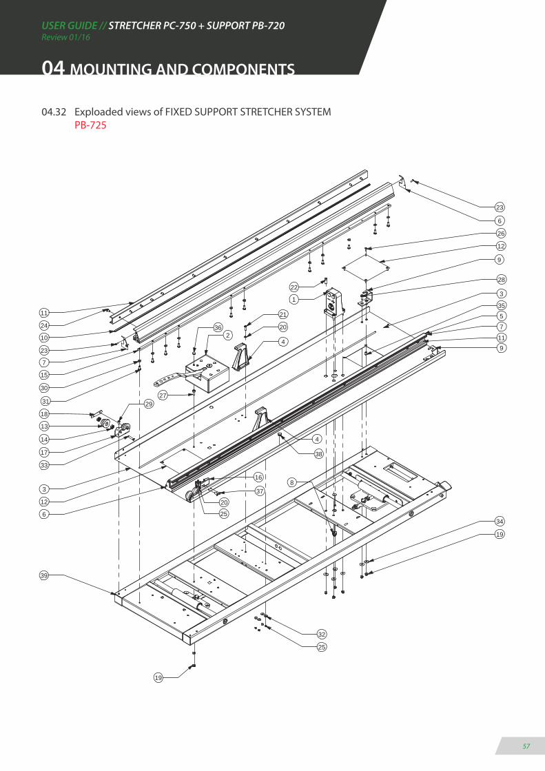
04.32 Exploaded views of FIXED SUPPORT STRETCHER SYSTEM PB-725
04 MOUNTING AND COMPONENTS
12
11
24
10
23
7
15
30
31
18
13
14
29
17
33
3
39
8
220
4
1
23
6
9
26
22
32
28
5
119
37
16
25
27
19
21
4
34
19
35
36
6
7
2012
38
3
25
USER GUIDE // STRETCHER PC-750 + SUPPORT PB-720Review 01/16
58
04 MOUNTING AND COMPONENTS
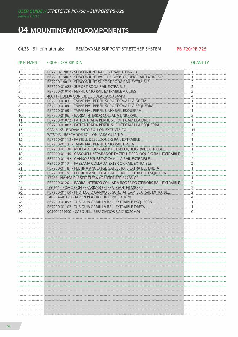
04.33 Bill of materials: REMOVABLE SUPPORT STRETCHER SYSTEM PB-720/PB-725
Nº ELEMENT CODE - DESCRIPTION QUANTITY
1 PB7200-12002 - SUBCONJUNT RAIL EXTRAIBLE PB-720 12 PB7200-13002 - SUBCONJUNT VARILLA DESBLOQUEIG RAIL EXTRAIBLE 13 PB7200-14012 - SUBCONJUNT SUPORT RODA RAIL EXTRAIBLE 24 PB7200-01022 - SUPORT RODA RAIL EXTRAIBLE 25 PB7200-01010 - PERFIL UNIO RAIL EXTRAIBLE A GUIES 26 40011 - RUEDA CON EJE DE BOLAS Ø75X24MM 47 PB7200-01031 - TAPAFINAL PERFIL SUPORT CAMILLA DRETA 18 PB7200-01041 - TAPAFINAL PERFIL SUPORT CAMILLA ESQUERRA 19 PB7200-01051 - TAPAFINAL PERFIL UNIO RAIL ESQUERRA 110 PB7200-01061 - BARRA INTERIOR COLLADA UNIO RAIL 211 PB7200-01072 - PATI ENTRADA PERFIL SUPORT CAMILLA DRET 112 PB7200-01082 - PATI ENTRADA PERFIL SUPORT CAMILLA ESQUERRA 113 CPA43-2Z - RODAMIENTO ROLLON EXCENTRICO 1414 WCST43 - RASCADOR ROLLON PARA GUIA TLV 415 PB7200-01112 - PASTELL DESBLOQUEIG RAIL EXTRAIBLE 116 PB7200-01121 - TAPAFINAL PERFIL UNIO RAIL DRETA 117 PB7200-01130 - MOLLA ACCIONAMENT DESBLOQUEIG RAIL EXTRAIBLE 118 PB7200-01140 - CASQUELL SEPARADOR PASTELL DESBLOQUEIG RAIL EXTRAIBLE 219 PB7200-01152 - GANXO SEGURETAT CAMILLA RAIL EXTRAIBLE 220 PB7200-01171 - PASSAMA COLLADA EXTERIOR RAIL EXTRAIBLE 221 PB7200-01181 - PLETINA ANCLATGE GATELL RAIL EXTRAIBLE DRETA 122 PB7200-01191 - PLETINA ANCLATGE GATELL RAIL EXTRAIBLE ESQUERRA 123 37285 - NANSA PLASTIC ELESA+GANTER REF. 37285-C9 124 PB7200-01201 - BARRA INTERIOR COLLADA RODES POSTERIORS RAIL EXTRAIBLE 225 166364 - POMO CON ESPARRAGO ELESA+GANTER M8X30 226 PB7200-01160 - PROTECCIÓ GANXO SEGURETAT CAMILLA RAIL EXTRAIBLE 227 TAPPLA-40X20 - TAPON PLASTICO INTERIOR 40X20 428 PB7200-01092 - TUB GUIA CAMILLA RAIL EXTRAIBLE ESQUERRA 129 PB7200-01102 - TUB GUIA CAMILLA RAIL EXTRAIBLE DRETA 130 005604059902 - CASQUELL ESPACIADOR 8.2X18X20MM 6

USER GUIDE // STRETCHER PC-750 + SUPPORT PB-720Review 01/16
59
04 MOUNTING AND COMPONENTS
Nº ELEMENT CODE - DESCRIPTION QUANTITY
31 PB7200-01220 - TOPE EXTRACCIÓ RAIL EXTRAIBLE 232 3110206301 - TORNILLO D-912 M-6X30 CINCADO 433 3110205151 - TORNILLO D-912 M5X10 CINCADO 834 31201051 - ARANDELA D-125 M5 CINCADA 235 3111305161 - TORNILLO ISO7380 M5X16 CINCADO 236 3111308301 - TORNILLO ISO7380 M8X30 CINCADO 837 31203063 - ARANDELA D-6798A PARA M6 PAVONADA 438 3111306121 - TORNILLO ISO-7380 M6X12 CINCADO 439 3110808201 - TORNILLO D-7991 M8X20 CINADO 1240 31201081 - ARANDELA D-125 M8 CINCADA 2041 3111308351 - TORNILLO ISO7380 M8X35 CINCADO 1442 31201061 - ARANDELA D-125 M6 CINCADA 1643 3110808301 - TORNILLO D-7991 M8X30 CINCADO 444 3110210301 - TORNILLO D-912 M-10X30 CINCADO 245 31305101 - TUERCA D-985 M-10 CINCADA 246 3111308161 - TORNILLO ISO7380 M8X16 CINCADO 447 3110206161 - TORNILLO D-912 M-6X16 CINCADO 1648 31305081 - TUERCA D-985 M-8 CINCADA 249 3111308451 - TORNILLO ISO7380 M8X45 CINCADO 250 314020802 - TUERCA REMACHABLE M-8 S-VALONA HEXAGONAL 251 2802000001 - TORNILLO M5 X10 TAPTITE PLANO 452 314020801 - TUERCA REMACHABLE M-8 GRAF SIN VALONA 653 3110208451 - TORNILLO D-912 M-8X45 CINCADO 654 PB7200-01231 - BARRA INTERIOR UNIO RAIL 2

04 MONTAJE Y DESPIECE

USER GUIDE // STRETCHER PC-750 + SUPPORT PB-720Review 01/16
61
39
1
23
47
42
12
32
53
6
41
11
43 24
2
18
41
40
15
34
35
18
17
2146
20
36
16
14
13
7
39
3314
5
4742
10
54
41
40
38
37
4840
49
6
4
44
45
8
4119
25
5029
28
27
52
30
40
3
26 31
4151
33
40
04 MOUNTING AND COMPONENTS
04.34 Exploaded views of REMOVABLE SUPPORT STRETCHER SYSTEM PB-720/PB-725

USER GUIDE // STRETCHER PC-750 + SUPPORT PB-720Review 01/16
62
04 MOUNTING AND COMPONENTS
04.35 Bill of materials: SET PLATE PB-720/PB-725
Nº ELEMENT CODE - DESCRIPTION QUANTITY
1 PB4100-01012A - SUBCONJUNT PLETINA COLLADA 12 PB4100-00462 - ANGLE SOPORT CABLE PER TENSOR 13 PB4010-00040 - TENSOR UNIVERSAL 14 31301071 - TUERCA D-934 M-7 CINCADA 15 PC6170-03291 - BRIDA SUBJECCIÓ BALDA 16 PB4100-00291 - VALDA FIXACIO 17 PA1481-4X18N - PASADOR ELASTICO D-1481 4X18 NEGRO 18 303-339 - MOLLA COMPRESSIÓ 55X13.75X2 19 KH2540 - COJINETE DE BOLAS 210 3110204201 - TORNILLO D-912 M4X20 CINCADO 111 31305041 - TUERCA D-985 M-4 CINCADA 112 3110405101 - TORNILLO D-933 M5X10 CINCADO 2

USER GUIDE // STRETCHER PC-750 + SUPPORT PB-720Review 01/16
63
04 MOUNTING AND COMPONENTS
04.36 Exploaded views of SET PLATEPB-720/PB-725
3
6
7
11
5
10
89
1
2
4
USER GUIDE // STRETCHER PC-750 + SUPPORT PB-720Review 01/16
64
04 MOUNTING AND COMPONENTS
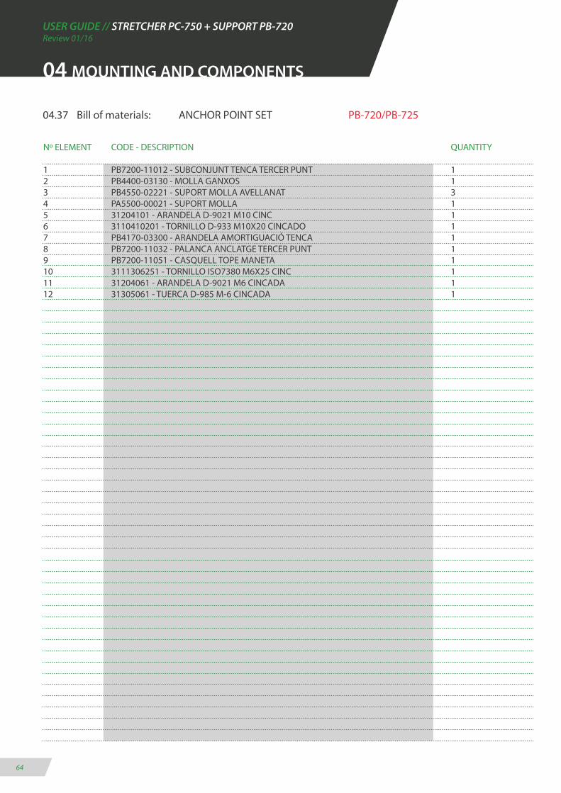
04.37 Bill of materials: ANCHOR POINT SET PB-720/PB-725
Nº ELEMENT CODE - DESCRIPTION QUANTITY
1 PB7200-11012 - SUBCONJUNT TENCA TERCER PUNT 12 PB4400-03130 - MOLLA GANXOS 13 PB4550-02221 - SUPORT MOLLA AVELLANAT 34 PA5500-00021 - SUPORT MOLLA 15 31204101 - ARANDELA D-9021 M10 CINC 16 3110410201 - TORNILLO D-933 M10X20 CINCADO 17 PB4170-03300 - ARANDELA AMORTIGUACIÓ TENCA 18 PB7200-11032 - PALANCA ANCLATGE TERCER PUNT 19 PB7200-11051 - CASQUELL TOPE MANETA 110 3111306251 - TORNILLO ISO7380 M6X25 CINC 111 31204061 - ARANDELA D-9021 M6 CINCADA 112 31305061 - TUERCA D-985 M-6 CINCADA 1

USER GUIDE // STRETCHER PC-750 + SUPPORT PB-720Review 01/16
65
04 MOUNTING AND COMPONENTS
04.38 Exploaded views of ANCHOR POINT SETPB-720/PB-725
4
3
7
3
10
6
9
11
1
8
3
2
5
12
USER GUIDE // STRETCHER PC-750 + SUPPORT PB-720Review 01/16
66
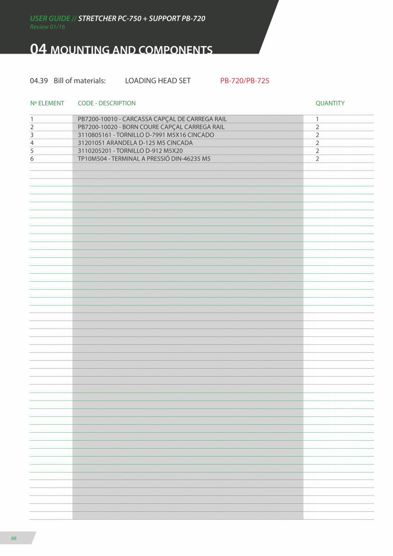
04.39 Bill of materials: LOADING HEAD SET PB-720/PB-725
Nº ELEMENT CODE - DESCRIPTION QUANTITY
1 PB7200-10010 - CARCASSA CAPÇAL DE CARREGA RAIL 12 PB7200-10020 - BORN COURE CAPÇAL CARREGA RAIL 23 3110805161 - TORNILLO D-7991 M5X16 CINCADO 24 31201051 ARANDELA D-125 M5 CINCADA 25 3110205201 - TORNILLO D-912 M5X20 26 TP10M504 - TERMINAL A PRESSIÓ DIN-46235 M5 2
04 MOUNTING AND COMPONENTS

USER GUIDE // STRETCHER PC-750 + SUPPORT PB-720Review 01/16
67
04 MOUNTING AND COMPONENTS
04.40 Exploaded views of LOADING HEAD SETPB-720/PB-725
4
5
2
1
3
6
USER GUIDE // STRETCHER PC-750 + SUPPORT PB-720Review 01/16
68
05 ELECTRICAL CIRCUIT DIAGRAM
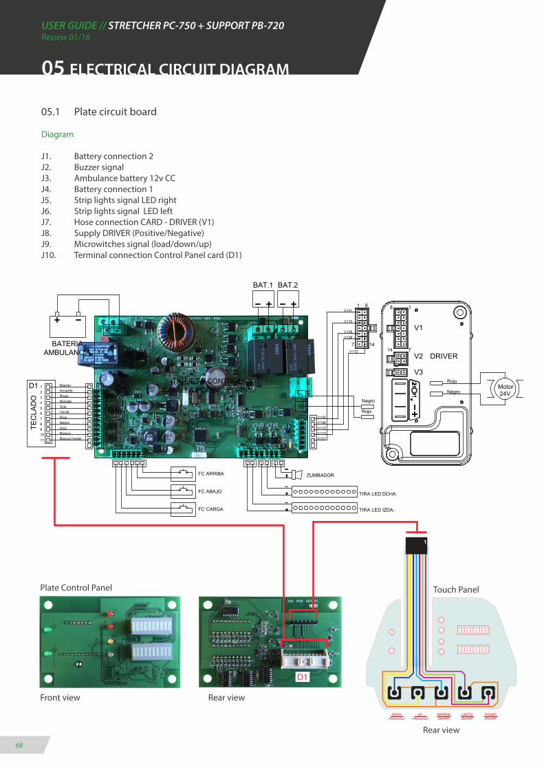
05.1 Plate circuit board
Diagram
J1. Battery connection 2J2. Buzzer signalJ3. Ambulance battery 12v CCJ4. Battery connection 1J5. Strip lights signal LED rightJ6. Strip lights signal LED leftJ7. Hose connection CARD - DRIVER (V1)J8. Supply DRIVER (Positive/Negative)J9. Microwitches signal (load/down/up)J10. Terminal connection Control Panel card (D1)
Plate Control Panel
Front view Rear view
Touch Panel
D1
Rear view

USER GUIDE // STRETCHER PC-750 + SUPPORT PB-720Review 01/16
69
05.2 Electrical wiring diagram
Wiring lines
A. Power input line (12v CC)B. Microswitch line load terminalC. Final microswitch line of superior runD. Electro-hydraulic group connection line (24v CC)E. Final micro-switch line of lower runF. Supply line left LED lightsG. Supply line right LED lightsH. Communication line of control panelI. Load line between support and ambulance (12v CC)
A
F
B
C
D
E
05 WIRING DIAGRAM
H
G
I


USER GUIDE // STRETCHER PC-750 + SUPPORT PB-720Review 01/16
71
06 GENERAL MAINTENANCE
CLEANING
Keeping the equipment cleaned is essential to ensu-re a good use and durability of the set. It is necessary to make a periodical thorough cleaning, especially in areas exposed to dirt that could suffer damages, such as gears, connectors, switches, etc. Do not use hi-gh-pressure cleaning, they can damage the electrical elements.
CONTROLS AND SELECTORS
Due to a heavy and continued use of the moving parts, such as controls and selectors, check them periodica-lly for a proper functioning. There may be failures on micro-switches and cabling; examine the fixations and electric or mechanical connections that could exist.
GREASE
Generally, every moving part should be greased. Our products leave the factory completely greased and lu-bricated, however, it is possible that with the time and usage of the product the elements degrease, either by loss of lubrication or by dirt. Clean and grase periodica-lly the affected zones according to the manufacturer’s specifications.
Verify that there are no loose, worn, or missing parts. Examine periodically every moving element to ensure that they are all tighten.
Do not grease the platform guide because of its sliding dry system.
WARNING: Do not lubricate the support once connec-ted to the electricity network.
WEAR AREAS
Regularly examining the system’s components to check if they are wearing out is a preventive measure that can reduce breakdowns. Verify possible lubricate leaks, grooves or bearings in poor condition.
MECHANICAL FIXING
Generally we call mechanical fixing to the components that are used to attach joint products, mainly screws and derivatives.
In some conditions of use, due to vibrations or impacts, many elements could lose their tightening torque or hold properties.
Periodically examine that no elements are unleashed, especially in the moving parts of the set. Take into ac-count and always respect the recommended tighte-ning torques.
REPLACEMENT OF COMPONENTS
This instruction manual does not include procedures for every part. The service staff typically substitutes cables, commutators and certain mechanical parts wi-thout any step by procedure.
The qualified service personnel must contact our sales department for information about ordering pieces and its installation.
MAKE SURE TO KEEP THESE AREAS FREE OF WATER AND HUMIDITY.TAKE SPECIAL CARE NOT TO WET THEM WHILE WASHING THE SET.

USER GUIDE // STRETCHER PC-750 + SUPPORT PB-720Review 01/16
72
07 LEGAL NOTICES
This document may coutain tehcnical inaccurancies or typographical errors.
Changes are periodically added to the information he-rein; these changes will be incorporated in new eddi-tions of the publication.
Promeba, S.L. reserves the right to make any modifica-tion or improvement in the products described in this publication if it is appropriate.
Promeba, S.L. may have patents or patent applications which address themes described in this document. The possesion of this document does not entitle no license to these patents.
The information contained in this document does not affect or change the specifications or product specifi-cations or warranties of Promeba, S.L.
No part of this document shall operate as express or implied license or compensation under the intellectual property rights of Promeba, S.L. or third party.
All the information contained in this document has been obtained in specific environments and it is pre-sented as an illustration. The results obtained in other operating environments may vary.
Promeba, S.L. can use or distribute the information that the client provides in whatecer way they see fit, without incurring any obligation with the client.
USER GUIDE // STRETCHER PC-750 + SUPPORT PB-720Review 01/16
73
08 PRODUCT WARRANTY
Promeba, S.L. warrants that their products have suc-cesfully passed all quality controls, both functional and material. The warranty period is 2 years from the date of purchase.
This warranty will only be granted when the original invoice or sales receipt (indicating the date of purcha-se, model and the distributor’s name) is presented to-gether with the defective product during the warranty period. Promeba, S.L. reserves the right to not offer the free warranty service if the indicated documents are not presented or if the information provided the consumer is false, incomplete or illegible.
1. This warranty shall not apply if the model’s name or the serial number has been altered, removed, disappeared or is illegible.
2. This warranty does not cover transportation costs or risks associated with the transport of product to and from Promeba, S.L.
3. This warranty does not cover any of the following cases:
a) Regular maintenance and repairation or replacement of parts from normal wear and tear.
b) Consumibles (components that may need periodic re-placement during the product’s life, such as non-chargea-ble batteries, bulbs, etc.)
c) Damages or defects resulting from the use, operation or improper treatment of the product and not caused by a normal use of it.
d) Damages arising from
i. Improper use, including:
- Treatment resulting in damages or physical changes, surface or appearance changes of the product.
- Installation, use or storage of the product in a manner inconsistent with the instructions described by Prome-ba, S.L.
- Product maintenance in a manner inconsistent with the inconsistent with the instructions of Promeba, S.L. for a proper maintenance.
- Installation or product use in a manner inconsistent with the technical or security standards of the country where it is used or installed.
ii. Use of components not supplied with the product or incorrect installation of accessory parts previously untested.
iii. States or defects system in which the product is incorporated with the exception of other products of Promeba, S.L. designed for its use with the product.
iv. Product use with accessories, periphersal units and other products of a type, condition or standard not es-tablished by Promeba, S.L.
v. The manufacturer or distributor shall be solely res-ponsible for determining the sending of parts for its re-paration or the replacement of the product in its enti-rety. In no circumstance shall operators be send to such reparation or product replacement.
Except in the cases mentioned above, Promeba, S.L. shall not give any guarantees in relation to the pro-duct, operation, accuracy, reliability or adaptability for an equipment logical purpose or any other type. If this exception is not lawful or established in the law, Pro-meba, S.L. shall limit or exclude their guarantees only to the extent that the applicable law permits it.
The only obligation of Promeba, S.L. regarding this warranty is to repair or replace the parts subjected to the terms and condition of this warranty.
Promeba, S.L. is not liable for loss or damages to pro-ducts, this warranty or others, including economic loss or not assessable damage; the price paid for the pro-duct; loss of profits, incomes, information, usufruct or use of the product or associated products or indirect loss or damage, accidental or critical.
This clause refers to whether the loss or damage is due to a product deterioration or inoperability associated to defects or unavallability of Promeba, S.L. that cau-sed a downtime, user’s time loss or a business interrup-tion.
In the cases in which the law prohibits or limits these responsability exclusions, Promeba, S.L. shall exclude or limit their responsability only to the extent that the law allows. For exemple, many countries forbid the ex-clusion or limitation of damages caused by negligence, gross negligence, willful misconduct, fraud and similar acts. The responsability of Promeba, S.L. in this warran-ty shall not exceed, in any case, the price paid for the product, but if the applicable law permits only respon-sability limitations of major responsabilities, these shall be applied.

ER-0687/1998
PROMEBA, S.L.
Ctra C-16 Km 59.5 · 08650 Sallent (Barcelona) · SPAINT. 93 837 12 00 · Fax 93 820 61 08
[email protected] · www.promeba.com
Todos los derechos reservados. Reservado el derecho ha modificaciones sin previo aviso.Promeba, S.L. no se considera responsabe de los daños causados por la falta o la inexactitud de la información aquí mencionada.
All rights reserved. Variations can be done whitout notice.Promeba, S.L. is to be considered not responsible for damages caused by the lack or the wrongness of the information here mentioned.