Electric Snow Thrower - OrderTree.comordertree.com/docs/573/60-3983-8_EN manual...
19
Electric Snow Thrower Owner's Manual TOLL-FREE HELPLINE: 1 866 523-5218 IMPORTANT: Read all safety rules and instructions carefully before using this product. 60-3983-8
Transcript of Electric Snow Thrower - OrderTree.comordertree.com/docs/573/60-3983-8_EN manual...

Electric Snow Thrower
Owner's ManualTOLL-FREE HELPLINE: 1 866 523-5218
IMPORTANT:Read all safety rules and instructions carefully before using this product.
60-3983-8
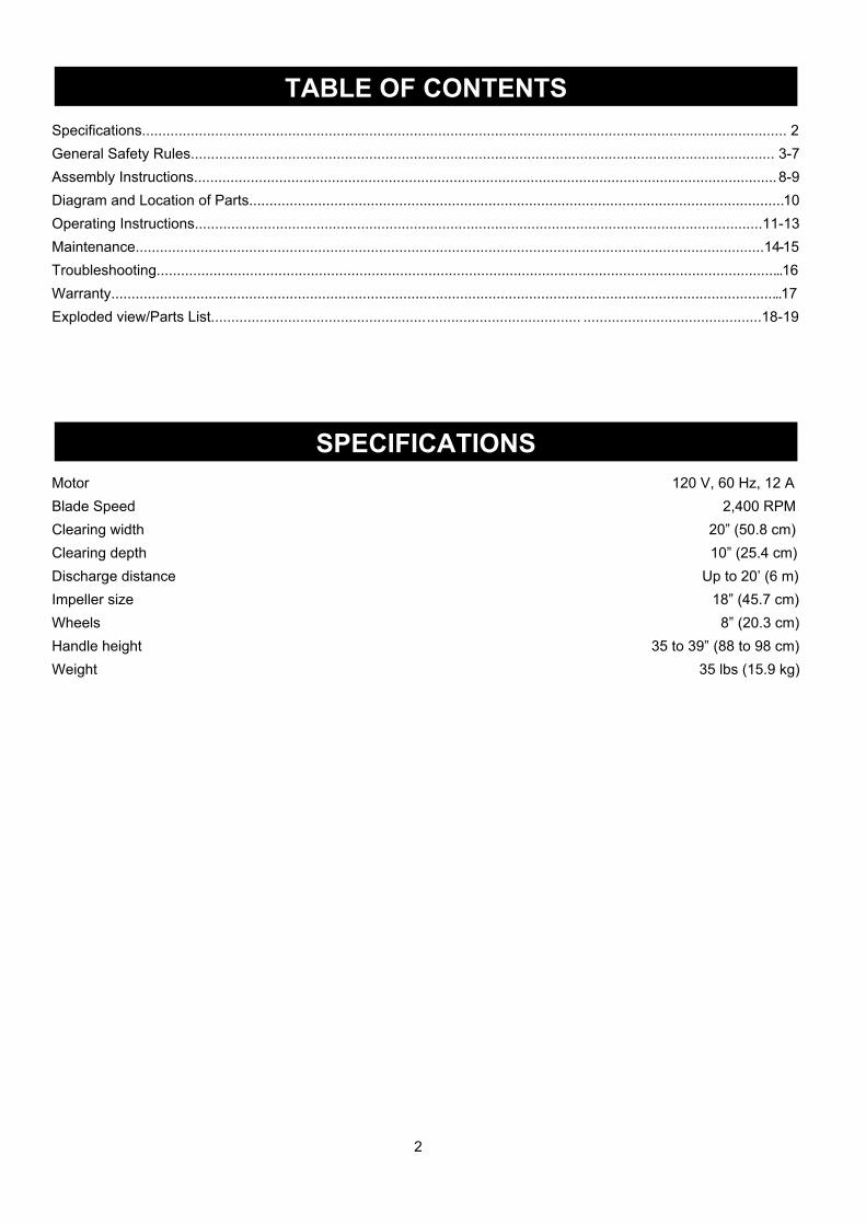
Specifications............................................................................................................................................................... 2General Safety Rules................................................................................................................................................ 3-7Assembly Instructions................................................................................................................................................ 8-9Diagram and Location of Parts....................................................................................................................................10Operating Instructions............................................................................................................................................11-13Maintenance...........................................................................................................................................................14-15Troubleshooting...........................................................................................................................................................16Warranty......................................................................................................................................................................17Exploded view/Parts List........................................................................................... ............................................18-19
Motor 120 V, 60 Hz, 12 ABlade Speed 2,400 RPMClearing width 20” (50.8 cm)Clearing depth 10” (25.4 cm)Discharge distance Up to 20’ (6 m)Impeller size 18” (45.7 cm)Wheels 8” (20.3 cm)Handle height 35 to 39” (88 to 98 cm)Weight 35 lbs (15.9 kg)
2
TABLE OF CONTENTS
SPECIFICATIONS
GENERAL SAFETY RULES
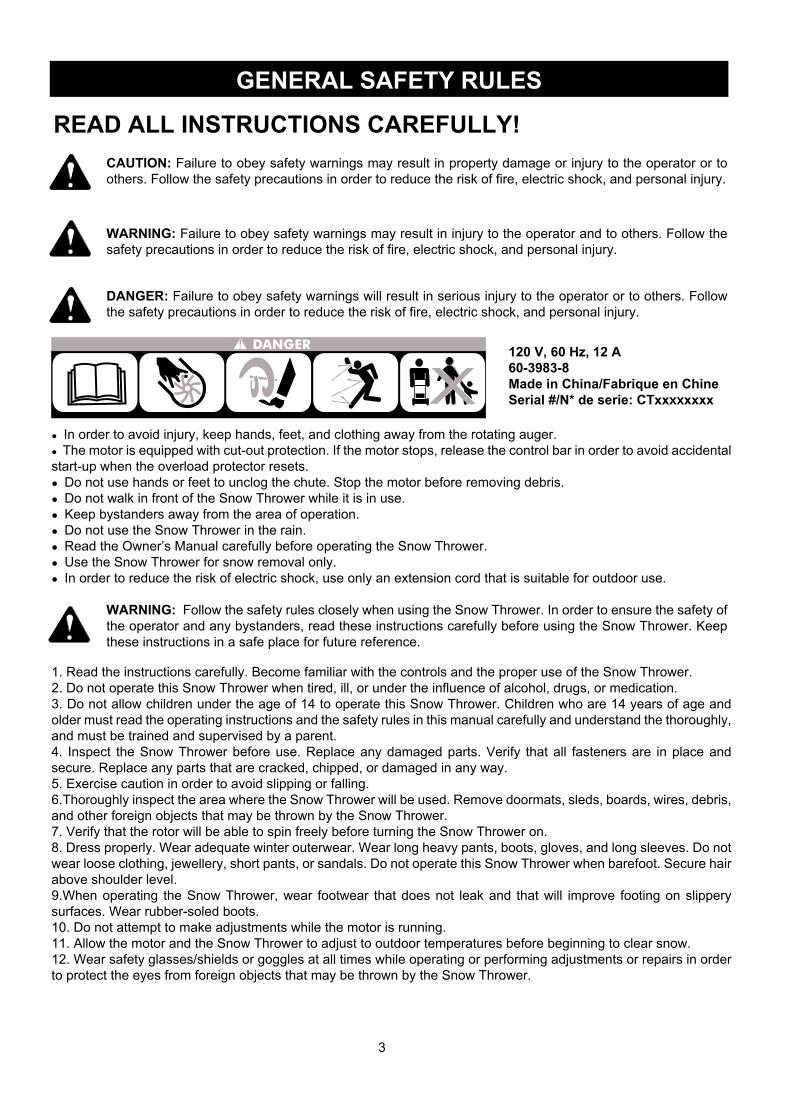
READ ALL INSTRUCTIONS CAREFULLY!CAUTION: Failure to obey safety warnings may result in property damage or injury to the operator or to others. Follow the safety precautions in order to reduce the risk of fire, electric shock, and personal injury.
WARNING: Failure to obey safety warnings may result in injury to the operator and to others. Follow the safety precautions in order to reduce the risk of fire, electric shock, and personal injury.
WARNING: Follow the safety rules closely when using the Snow Thrower. In order to ensure the safety of the operator and any bystanders, read these instructions carefully before using the Snow Thrower. Keep these instructions in a safe place for future reference.
DANGER: Failure to obey safety warnings will result in serious injury to the operator or to others. Follow the safety precautions in order to reduce the risk of fire, electric shock, and personal injury.
● In order to avoid injury, keep hands, feet, and clothing away from the rotating auger.● The motor is equipped with cut-out protection. If the motor stops, release the control bar in order to avoid accidental start-up when the overload protector resets.● Do not use hands or feet to unclog the chute. Stop the motor before removing debris.● Do not walk in front of the Snow Thrower while it is in use.● Keep bystanders away from the area of operation.● Do not use the Snow Thrower in the rain.● Read the Owner’s Manual carefully before operating the Snow Thrower.● Use the Snow Thrower for snow removal only.● In order to reduce the risk of electric shock, use only an extension cord that is suitable for outdoor use.
1. Read the instructions carefully. Become familiar with the controls and the proper use of the Snow Thrower.2. Do not operate this Snow Thrower when tired, ill, or under the influence of alcohol, drugs, or medication.3. Do not allow children under the age of 14 to operate this Snow Thrower. Children who are 14 years of age and older must read the operating instructions and the safety rules in this manual carefully and understand the thoroughly, and must be trained and supervised by a parent.4. Inspect the Snow Thrower before use. Replace any damaged parts. Verify that all fasteners are in place and secure. Replace any parts that are cracked, chipped, or damaged in any way.5. Exercise caution in order to avoid slipping or falling.6.Thoroughly inspect the area where the Snow Thrower will be used. Remove doormats, sleds, boards, wires, debris, and other foreign objects that may be thrown by the Snow Thrower.7. Verify that the rotor will be able to spin freely before turning the Snow Thrower on.8. Dress properly. Wear adequate winter outerwear. Wear long heavy pants, boots, gloves, and long sleeves. Do not wear loose clothing, jewellery, short pants, or sandals. Do not operate this Snow Thrower when barefoot. Secure hair above shoulder level.9.When operating the Snow Thrower, wear footwear that does not leak and that will improve footing on slippery surfaces. Wear rubber-soled boots.10. Do not attempt to make adjustments while the motor is running.11. Allow the motor and the Snow Thrower to adjust to outdoor temperatures before beginning to clear snow.12. Wear safety glasses/shields or goggles at all times while operating or performing adjustments or repairs in order to protect the eyes from foreign objects that may be thrown by the Snow Thrower.
120 V, 60 Hz, 12 A60-3983-8Made in China/Fabrique en ChineSerial #/N* de serie: CTxxxxxxxx
3
4
GENERAL SAFETY RULES
Extension Cord
WARNING: In order to prevent electric shock, use an extension cord that is suitable for outdoor use.
WARNING:In order to reduce the risk of electric shock when operating this Snow Thrower, use only a CSA-listed extension cord that is approved for outdoor use, such as Type SJTW, 16AWG, and that has a lower temperature rating of -40° F (-40° C).
• Ground Fault Circuit Interrupter (GFCI) protection should be provided on the circuit(s) or outlet(s) that will be used for this Snow Thrower. For an extra measure of safety, use a receptacle that has built-in GFCI protection.• The nameplate on the Snow Thrower indicates the voltage used. Do not connect the Snow Thrower to an AC circuit that provides a different voltage from the voltage that is indicated on the nameplate.
• Inspect the extension cord and the power cord on a regular basis. Look for deterioration, cuts, or cracks in the insulation. Inspect the connections for damage. Repair or replace the extension cord or the power cord if any damage is found.• Verify that the rotor and all moving parts have come to a complete stop, and disconnect the Snow Thrower from the power supply in order to prevent accidental start-ups before cleaning or performing any inspections or repairs.• Do not abuse the extension cord. Do not carry the Snow Thrower by the power cord or pull on the cord in order to disconnect it from the receptacle.• Keep the extension cord away from heat, oil, and sharp edges in order to prevent damage.• If the extension cord is damaged in any manner while it is plugged in, disconnect it from the outlet immediately.• Prevent any possible disconnection of the power cord from the extension cord while the Snow Thrower is in use by using the cord retainer and guide bar. Refer to the section entitled Using the Cord Retainer.• Avoid accidental start-ups. Do not carry the Snow Thrower with a finger on the switch while it is plugged in. Verify that the switch is in the "OFF" position before plugging in the Snow Thrower.• Unplug the Snow Thrower and allow it to cool down before putting it into storage. Store the Snow Thrower indoors.• Unplug the Snow Thrower when it is not in use and before performing any maintenance or repairs.
Amperage rating of the tool(120 V circuit only)
Total length of the extension cord
More than Not more than
25’ (7.6 m) 50’ (15.2 m) 100’ (30.4 m) 150’ (45.7 m)
Minimum Gauge for the extension cord (AWG)
Recommended size of extension cords
0 12 16 16 14 14
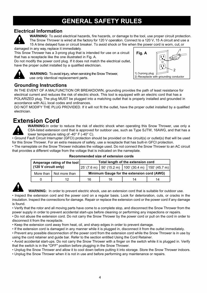
Electrical Information WARNING: To avoid electrical hazards, fire hazards, or damage to the tool, use proper circuit protection. The Snow Thrower is wired at the factory for 120 V operation. Connect to a 120 V, 15 A circuit and use a 15 A time delayed fuse or circuit breaker. To avoid shock or fire when the power cord is worn, cut, or damaged in any way, replace it immediately.This Snow Thrower has a 3-prong plug that is intended for use on a circuit that has a receptacle like the one illustrated in Fig. A.Do not modify the power cord plug. If it does not match the electrical outlet, have the proper outlet installed by a qualified electrician.
WARNING: To avoid injury, when servicing the Snow Thrower, use only identical replacement parts.
IN THE EVENT OF A MALFUNCTION OR BREAKDOWN, grounding provides the path of least resistance for electrical current and reduces the risk of electric shock. This tool is equipped with an electric cord that has a POLARIZED plug. The plug MUST be plugged into a matching outlet that is properly installed and grounded in accordance with ALL local codes and ordinances.DO NOT MODIFY THE PLUG PROVIDED. If it will not fit the outlet, have the proper outlet installed by a qualified electrician.
Grounding Instructions
1
21) 3-prong plug2) Receptacle with grounding conductor
Fig. A

5
GENERAL SAFETY RULES
FOLLOW THESE RULES WHILE OPERATING THE SNOWTHROWER• Walk. Do not run.• Verify that the Snow Thrower is not in contact with anything before turning it on.• Stay away from the discharge opening at all times. Keep face, hands, and feet away from concealed, moving, or rotating parts.• Be attentive when using the Snow Thrower, and stay alert for holes in the terrain and other hidden hazards or traffic.• Do not use the Snow Thrower on a gravel or crushed rock surface. Use extreme caution when crossing gravel/crushed rock drives, walks, or roads.• Move up and down slopes when clearing snow. Do not go across a slope. Use caution when changing direction. Do not use this Snow Thrower to clear snow from steep slopes.• Do not attempt to use the Snow Thrower on a roof or on any steeply inclined slippery surface.• Do not operate the Snow Thrower if the guards, plates, and other safety protective devices are not in place.• Do not operate the Snow Thrower near glass enclosures, automobiles, trucks, window wells, drop-offs, etc. without properly adjusting the angle of the snow discharge. Keep children and pets away from the work area.• Do not force or overload the Snow Thrower. The Snow Thrower will perform better and safer when it is used at the rate that it was designed to work at.• Do not operate the Snow Thrower at high speeds on slippery surfaces. Look behind, and exercise caution when backing up.• Do not direct the discharge toward people, and do not allow anyone to move in front of the Snow Thrower while it is in use.• Wear safety glasses or goggles that meet ANSI Z87.1 standards, and wear ear/hearing protection when using this Snow Thrower.• Use the Snow Thrower in daylight or in good artificial light.• Avoid accidental start-ups. Remain in the starting position when turning the Snow Thrower on. The operator and the Snow Thrower must be in a stable position during start-up. See the section entitled Starting/Stopping Instruc-tions.
6
GENERAL SAFETY RULES
FOLLOW THESE RULES WHILE OPERATING THE SNOWTHROWER• Use the proper tool. Only use this Snow Thrower for the purpose that it was designed for.• Do not overreach. Always keep proper footing and balance.• Hold the Snow Thrower with both hands while it is in use. Keep a firm grip on the handles or the grips.• Keep hands, face, and feet away from all moving parts. Do not touch or try to stop the impeller while it is rotating.• If the impeller does not rotate freely due to frozen ice, thaw the Snow Thrower thoroughly before attempting to use it.• Keep the impeller clear of debris.• Do not attempt to clear the impeller while the motor running or while the Snow Thrower is plugged it. Turn the motor off and unplug the Snow Thrower from the extension cord or the outlet.• Keep clothing and body parts away from the rotor.• Do not operate the motor at a faster speed than necessary. Do not run the motor at high speed while not clearing snow.• Stop the motor when snow clearing is delayed or when moving from one location to another.• Unplug the Snow Thrower when it is being transported and when it is not in use.• After striking a foreign object, turn the Snow Thrower off and unplug it, and then inspect it for damage. Repair any damage before restarting and using the Snow Thrower.• If the Snow Thrower starts to vibrate abnormally, stop the Snow Thrower immediately and attempt to determine the cause. Vibration is generally an indication of danger.• Stop the motor and unplug the Snow Thrower whenever the operator is not in the operating position, before unclogging the impeller, and before making any repairs, adjustments, or inspections.• Do not discharge snow onto public roads or near moving traffic.• Allow the Snow Thrower to run for a few minutes after clearing snow in order to prevent moving parts from freez-ing.• Use only the manufacturer's original replacement parts and accessories for this Snow Thrower. The use of unau-thorized parts or accessories could lead to serious injury to the user or damage the Snow Thrower, and will void the warranty.• Do not use the Snow Thrower in the hand held position. Do not pick up the Snow Thrower while it is plugged and running. The Snow Thrower is designed to travel along the ground.

7
GENERAL SAFETY RULES
OTHER SAFETY WARNINGS• Verify that the Snow Thrower is secure while transporting.• Store the Snow Thrower in a dry area, locked up or high enough to prevent unauthorized use or damage, and out of the reach of children.• Do not douse or squirt the unit with water or any other liquid. Keep handles dry, clean, and free of debris. Clean the Snow Thrower after each use. See the section entitled Cleaning and Storage.• If the labels on the Snow Thrower become defaced or start to lift off, contact the Toll-Free Helpline, at 1-866-523-5218.• Keep these instructions in a safe place for future reference. Refer to them often, and use them to instruct other users. Anyone who uses this Snow Thrower must read these instructions carefully.• Maintain the Snow Thrower with care. Follow the instructions for lubricating and changing accessories.

8
ASSEMBLY INSTRUCTIONSAssembling the Handle (Fig. 1)1. Remove any packing material that may have been inserted between the upper and lower handles for shipping purposes.2. Align the holes (4) on the upper handle (1) with the holes on the middle handle (2). Insert the bolts (5), and use the wing nuts (6) to tighten them. (Fig. 1.1)3. Align the holes (7) on the middle handle (2) and the lower handle (3). Insert the bolts (5), and tighten them using the wing nuts (6) provided. (Fig. 1.2)
Assembling the Discharge Chute (Fig. 1)
Note: Do not overtighten the bolts.
Fig. 1.3
Fig. 1.2
Fig. 1.1
Fig. 1
8
9
10
11 1212 13
1516
17
14
1. Position the chute deflector (8) over the discharge chute (9), and align the mounting holes. (Fig. 1.3)2.
3.4. Insert a rubber washer (15) between the chute deflector (8) and the discharge chute, maintaining the alignment of the holes (17).5. Attach the chute deflector to the discharge chute using 2 carriage bolts (14), 4 washers (15), and 2 locknuts (16).
Insert a rubber washer (12) between the chute deflector (8) and the discharge chute, maintaining the alignment of the holes (10).Attach the chute deflector to the discharge chute using a carriage bolt (11), 2 washers (12), and a locknut (13).
5 4 6
5 7 6
1
2
3
9
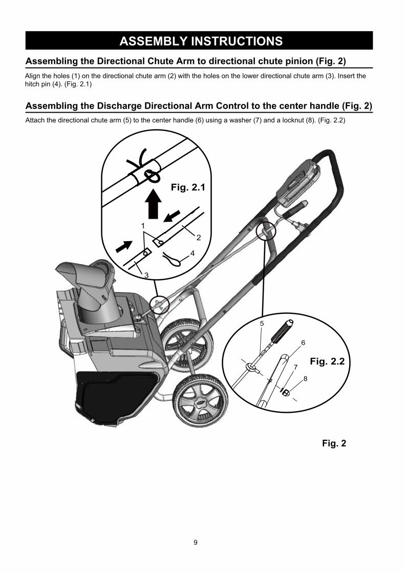
ASSEMBLY INSTRUCTIONSAssembling the Directional Chute Arm to directional chute pinion (Fig. 2)
Fig. 2
Attach the directional chute arm (5) to the center handle (6) using a washer (7) and a locknut (8). (Fig. 2.2)
Assembling the Discharge Directional Arm Control to the center handle (Fig. 2)
Align the holes (1) on the directional chute arm (2) with the holes on the lower directional chute arm (3). Insert thehitch pin (4). (Fig. 2.1)
7
5
6
8
Fig. 2.2
Fig. 2.1
4
12
3
10
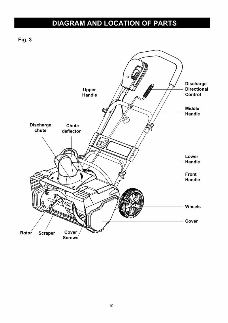
DIAGRAM AND LOCATION OF PARTS
Fig. 3
UpperHandle
MiddleHandle
LowerHandle
FrontHandle
Chute deflector
Dischargechute
Wheels
CoverScrews
Scraper
DischargeDirectionalControl
Rotor
Cover

11
OPERATING INSTRUCTIONS
Starting the Snow Thrower
Using the Switch
Operating tips
Fig. 4
WARNING: Avoid accidental start-ups. Verify that the operator is in the starting position when using the snow thrower. In order to avoid serious injury, the operator and unit must be in a stable position when start-ing the Snow Thrower.
This Snow Thrower is equipped with a special safety switch. In order to operate the switch, insert one finger into the opening, and push the lever out so that it can be grasped along with the upper handle. Pull the lever back in order to turn the Snow Thrower on, and hold it against the upper handle in order to keep it running. To turn the Snow Thrower off, simply release the lever.
Caution: Do no attempt to override the operation of this safety switch.
WARNING: If the Snow Thrower hits a foreign object while it is in use, the object could be thrown in the direction of the operator or a bystander. Thrown objects could cause serious personal injury. Keep the area to be cleared free of all foreign objects that may be picked up and thrown by the rotor blades.
NOTE: The chute crank makes a noise as it is turned. This is normal.The deflector handle (1) that is located on the top of the discharge chute controls the height of the snow stream (Fig. 4). Adjust the height of the snow stream by raising orlowering the chute deflector
• Keep children and pets away from the operating area.• Keep the area to be cleared free of stones, toys, or other foreign objects that the rotor blades can throw. Such items may be covered by a snowfall and go unnoticed. If the Snow Thrower strikes an obstruction or a foreign object during operation, stop the Snow Thrower, unplug the extension cord, remove the obstruction, and inspect the Snow Thrower for damage.• Rotate the chute crank clockwise in order to move the discharge chute to the left, or rotate it counter-clockwise in order to move the chute to the right.
Overload Protection SwitchThis Snow Thrower is equipped with an overload protection switch in order to protect the supply circuit from short circuit overloads. Follow these steps if the switch pops out:1. Release the switch bar, and allow the Snow Thrower to stop and cool down for a minute.2. Press the overload switch in order to reset it. Resume operation (Fig. 5).
Follow these steps if the switch pops out again shortly after the first time:1. Allow the Snow Thrower to stop and cool down for 15 to 30 minutes.2. After the Snow Thrower has cooled down, press the overload switch in order to reset it. Resume operation.
If the overload protection switch does not stay in, or if it continues to pop out during operation, contact the Toll-Free Helpline, at 1-866-523-5218.
1
12
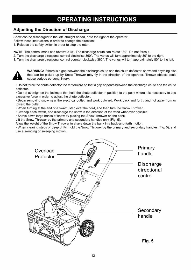
OPERATING INSTRUCTIONSAdjusting the Direction of DischargeSnow can be discharged to the left, straight ahead, or to the right of the operator.Follow these instructions in order to change the direction:1. Release the safety switch in order to stop the rotor.
NOTE: The control crank can revolve 810°. The discharge chute can rotate 180°. Do not force it.2. Turn the discharge directional control clockwise 360°. The vanes will turn approximately 80° to the right.3. Turn the discharge directional control counter-clockwise 360°. The vanes will turn approximately 80° to the left.
WARNING: If there is a gap between the discharge chute and the chute deflector, snow and anything else that can be picked up by Snow Thrower may fly in the direction of the operator. Thrown objects could cause serious personal injury.
• Do not force the chute deflector too far forward so that a gap appears between the discharge chute and the chute deflector.• Do not overtighten the locknuts that hold the chute deflector in position to the point where it is necessary to use excessive force in order to adjust the chute deflector.• Begin removing snow near the electrical outlet, and work outward. Work back and forth, and not away from or toward the outlet.• When turning at the end of a swath, step over the cord, and then turn the Snow Thrower.• Overlap each swath, and discharge the snow in the direction of the wind whenever possible.• Shave down large banks of snow by placing the Snow Thrower on the bank.Lift the Snow Thrower by the primary and secondary handles only (Fig. 5).Allow the weight of the Snow Thrower to shave down the bank in a back-and-forth motion.• When clearing steps or deep drifts, hold the Snow Thrower by the primary and secondary handles (Fig. 5), and use a swinging or sweeping motion.
PrimaryhandleOverload
Protector
Secondaryhandle
Fig. 5
Dischargedirectionalcontrol
13
OPERATING INSTRUCTIONS
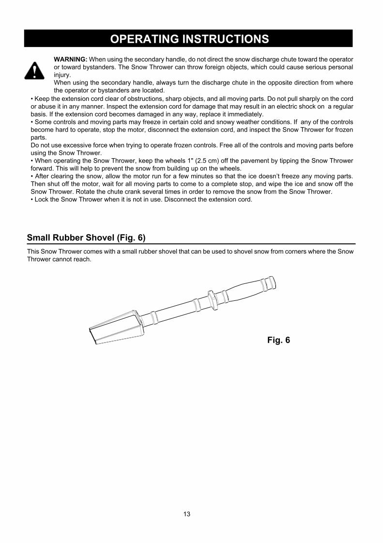
Fig. 6
Small Rubber Shovel (Fig. 6)This Snow Thrower comes with a small rubber shovel that can be used to shovel snow from corners where the Snow Thrower cannot reach.
WARNING: When using the secondary handle, do not direct the snow discharge chute toward the operator or toward bystanders. The Snow Thrower can throw foreign objects, which could cause serious personal injury.When using the secondary handle, always turn the discharge chute in the opposite direction from where the operator or bystanders are located.
• Keep the extension cord clear of obstructions, sharp objects, and all moving parts. Do not pull sharply on the cord or abuse it in any manner. Inspect the extension cord for damage that may result in an electric shock on a regular basis. If the extension cord becomes damaged in any way, replace it immediately.• Some controls and moving parts may freeze in certain cold and snowy weather conditions. If any of the controls become hard to operate, stop the motor, disconnect the extension cord, and inspect the Snow Thrower for frozen parts.Do not use excessive force when trying to operate frozen controls. Free all of the controls and moving parts before using the Snow Thrower.• When operating the Snow Thrower, keep the wheels 1" (2.5 cm) off the pavement by tipping the Snow Thrower forward. This will help to prevent the snow from building up on the wheels.• After clearing the snow, allow the motor run for a few minutes so that the ice doesn’t freeze any moving parts. Then shut off the motor, wait for all moving parts to come to a complete stop, and wipe the ice and snow off the Snow Thrower. Rotate the chute crank several times in order to remove the snow from the Snow Thrower.• Lock the Snow Thrower when it is not in use. Disconnect the extension cord.
14
MAINTENANCE
Servicing
Replacing the Scraper
Replacing the Rotor
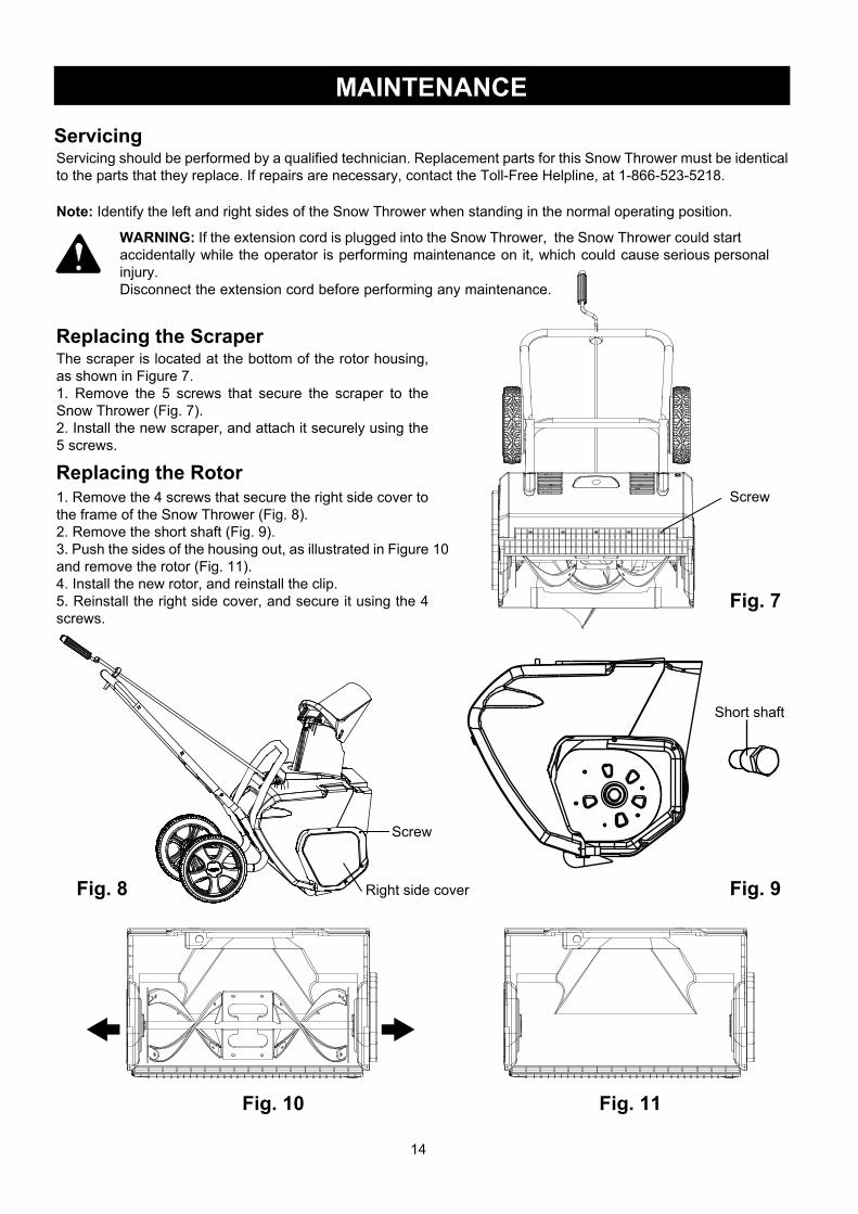
Fig. 7
Fig. 10 Fig. 11
Fig. 9Fig. 8
Screw
Screw
Right side cover
Short shaft
Servicing should be performed by a qualified technician. Replacement parts for this Snow Thrower must be identical to the parts that they replace. If repairs are necessary, contact the Toll-Free Helpline, at 1-866-523-5218.
Note: Identify the left and right sides of the Snow Thrower when standing in the normal operating position.
WARNING: If the extension cord is plugged into the Snow Thrower, the Snow Thrower could start accidentally while the operator is performing maintenance on it, which could cause serious personal
injury.Disconnect the extension cord before performing any maintenance.
The scraper is located at the bottom of the rotor housing, as shown in Figure 7.1. Remove the 5 screws that secure the scraper to the Snow Thrower (Fig. 7).2. Install the new scraper, and attach it securely using the 5 screws.
1. Remove the 4 screws that secure the right side cover to the frame of the Snow Thrower (Fig. 8).2. Remove the short shaft (Fig. 9).3. Push the sides of the housing out, as illustrated in Figure 10 and remove the rotor (Fig. 11).4. Install the new rotor, and reinstall the clip.5. Reinstall the right side cover, and secure it using the 4 screws.

15
MAINTENANCEReplacing the Large Belt
Storage
ScrewLeft side cover
BeltLargepulley
Bearing
Smallpulley
Fig. 12Fig. 13
BeltLargepulley
Bearing
Smallpulley
Fig. 14
1. Remove the 4 screws that secure the left side plate to the frame of the Snow Thrower (Fig. 12). Remove the side plate.2. Pull the bearing away from the small pulley. Remove the belt from the large pulley and the small pulley that is located inside the housing (Fig.13).
3. Position the new belt over the small pulley (Fig.14).4. Rotate the rotor with the left hand while positioning the belt on the large pulley with the right hand (Fig.14).5. Install the left side cover, and secure it using the 4 screws.
1. Run the Snow Thrower for a few minutes in order to melt any snow that may be left on the Snow Thrower.2. Disconnect the extension cord from the Snow Thrower.3. Inspect the extension cord thoroughly for signs of wear or damage. Replace it if it is worn or damaged.4. Inspect the Snow Thrower thoroughly for worn, loose, or damaged parts. If any parts must be repaired or replaced, contact the Toll-Free Helpline, at 1-866-523-5218.5. Store the extension cord with the Snow Thrower.6. Store the Snow Thrower in a clean, dry place. Cover it in order to provide added protection.
16
TROUBLESHOOTING
The belt is damaged.
The scraper is worn.
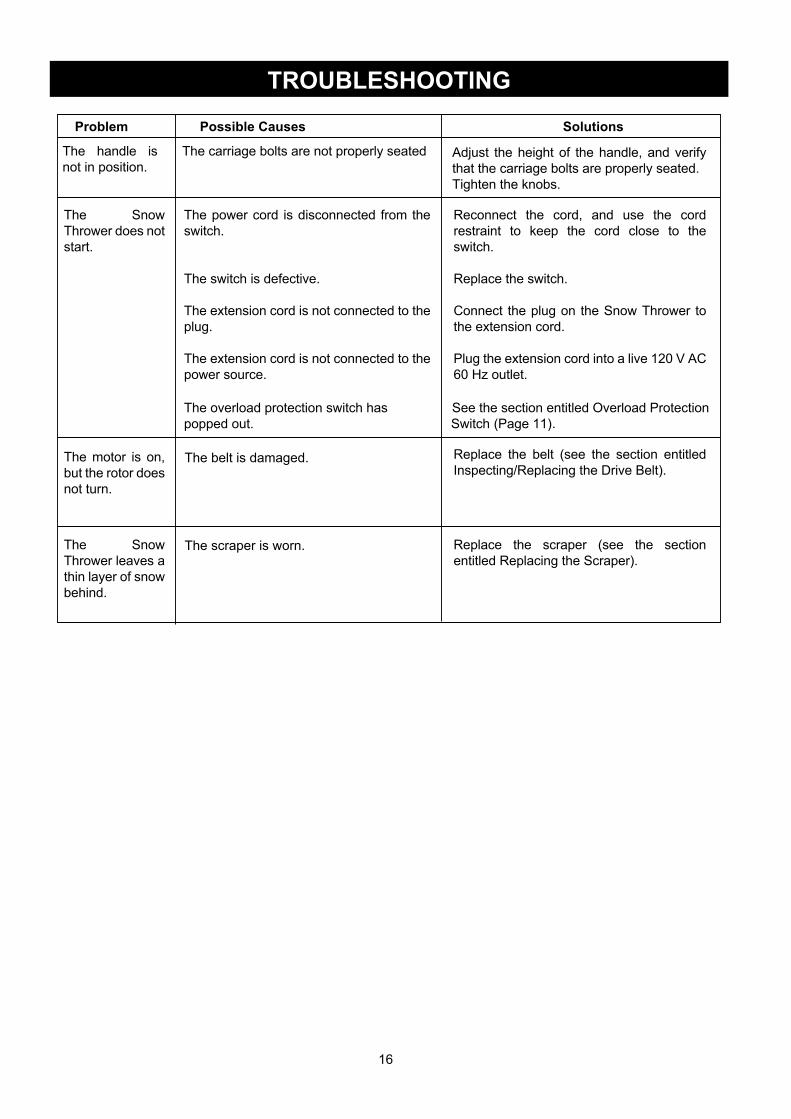
Problem Possible Causes Solutions
The handle is not in position.
The Snow Thrower does not start.
The motor is on, but the rotor does not turn.
The Snow Thrower leaves a thin layer of snow behind.
The carriage bolts are not properly seated
The power cord is disconnected from the switch.
The switch is defective.
The extension cord is not connected to the plug.
The extension cord is not connected to the power source.
The overload protection switch has See the section entitled Overload Protection
popped out. Switch (Page 11).
Reconnect the cord, and use the cord restraint to keep the cord close to the switch.
Replace the switch.
Connect the plug on the Snow Thrower to the extension cord.
Plug the extension cord into a live 120 V AC 60 Hz outlet.
Replace the belt (see the section entitled Inspecting/Replacing the Drive Belt).
Replace the scraper (see the section entitled Replacing the Scraper).
Adjust the height of the handle, and verify that the carriage bolts are properly seated.Tighten the knobs.

17
WARRANTY
For TWO YEARS from the date of purchase within Canada, YARDWORKS CANADA will, at its option, repair or replace for the original purchaser, free or charge, any part or parts found to be defective in material or workmanship.
This warranty does not cover:
1. Any part which has become inoperative due to misuse, commercial use, abuse, neglect, accident, improper maintenance or alteration; or 2. The unit, if it has not been operated and/or maintained in accordance with the owner's manual;or 3.Normal wear, except as noted below; 4.Routine maintenance items such as lubricants, blade sharpening; 5.Normal deterioration of the exterior finish due to use or exposure.
Full One Hundred Twenty Days Warranty on Normal Wear Parts: Normal wear parts are defined as Impellers, belts and tires. These parts are warranted to the original purchaser to be free from defects in material and workmanship
for a period of one hundred twenty (120) days from the date of retail purchase.
How to Obtain Service: Warranty service is available, with proof of purchase, through your local authorized service dealer or distributor. If you do not know the dealer or distributor in your area, please call toll free 1 866 523-5218. YARDWORKS will not accept the return of a complete unit unless prior written permission has been extended by YARDWORKS CANADA.
Transportation Charges: Transportation charges for the movement of any power equipment unit or attachment are the responsibility of the purchaser. The purchaser must pay transportation charges for any part submitted for replacement under this warranty unless such return is requested in writing by YARDWORKS CANADA.
Other Warranties: All other warranties, express or implied, including any implied warranty of merchantability is limited in its duration to that set forth in this express limited warranty. The provisions as set forth in this warranty provide the sole and exclusive remedy of YARDWORKS CANADA obligations arising from the sale of its products.
YARDWORKS CANADA will not be liable for incidental or consequential loss or damage.
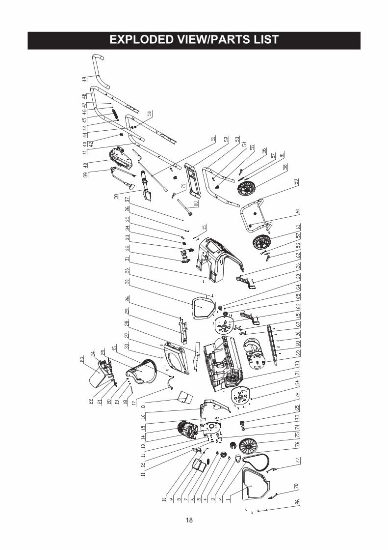
EXPLODED VIEW/PARTS LIST
18

EXPLODED VIEW/PARTS LIST
91
Item No. Description Qty Item No. Description Qty
1 33306100 Left side board
2 3290198 Belt 3 34901100 Strap
1
11
4 33212100 Tensioner fix shaft
1
5 32104100 Tensioner bearing
1
6 33211100 Tensioner shaft
2
7 33903100 TMotor vent coverensioner spring
Snow spade
1
8 34165100
Pigtail cable
1
9 32201100 Locknut
Switch assembly
1
10 33305100 Tensioner bracket
Middle handle
1
11 3290699 Washer
1
12 32203100 Cross screw
Soft grip sponge1
13 33301100-2 Motor support
1
14 31120100-1 Motor assembly
Panel 1
15 3220505 Screw
Front handle 1
16 34120100-1 Waterproof bracket
Rubber sleeve
4
17 33378100
4
18 32208100 CroMotor clamp
ss screw
Front support
2
19 32210100 Washer
Short shaft
2
20 32209100 Nut
Cross screw
1
21 3410835-5 Knob
Waterproof bearing
1
22 32215100 Washer
2
23 34111100-1 Chute deflector
1
24 32216100 Hex screw
Inner cord clamp
2
25 34110100-2
Vane
1
26 32207100 Cross screw
Impellor assembly
12
27 34104100-2
Front cover
2
28
1
29
4
30
1
31
1
32 34160100 Pinion bracket3416110034162100
Plate
1
33
1
3
363738
4 Square bushing
2
35 33260100
Pulley wheel support shaft21
1111111271741191112124121201
1111111
3940
41424344454647484950515253545556575859606162636465666768697071727374
Right side board33307100Rear cover34102100-2
3411810031107100A3630235-1
3320710Screw3330499Rubber3420199Washer3290299Handle3410499-1Washer3330211Retaining ring32901251
0-1
Upper handle311081003490137-
Nut3290599
Rear rocker33214100-3
1
3331010033205100
Bolt3220436Knob3410835-4Split pin 3290135Wheel cover
8” Wheel (right)
34108229
Lower handle33206100A
A
34250100
34204229-2
8” Wheel (left)34204229-13330410033201100A3220610
32102100Right support
Left support
33309100
0
34105100
34101100-2
34158100
31118100
33308100Nut3220651
Washer3221710033203100A
Driver wheel 176 34109100-1Left barrier chip 177 33273100Right barrier chip 178 33274100
Upper rocker 180 33214100-2Hitch pin 179 3320643
Washer 281 3220898
Pulley wheel assembly 175 31110100A
Discharge chute
Pin32201450 1Screw
32901261 11
Locknut
Out chute cover
34106100-2 Inlet chute cover34121100A 2Waterproof support