Electric Rollerdoor with ‘J’ Brackets · ELECTRIC ROLLERDOOR – J BRACKETS Introduction -5-...
24
Electric Rollerdoor with ‘J’ Brackets Installation Instructions ENG
Transcript of Electric Rollerdoor with ‘J’ Brackets · ELECTRIC ROLLERDOOR – J BRACKETS Introduction -5-...
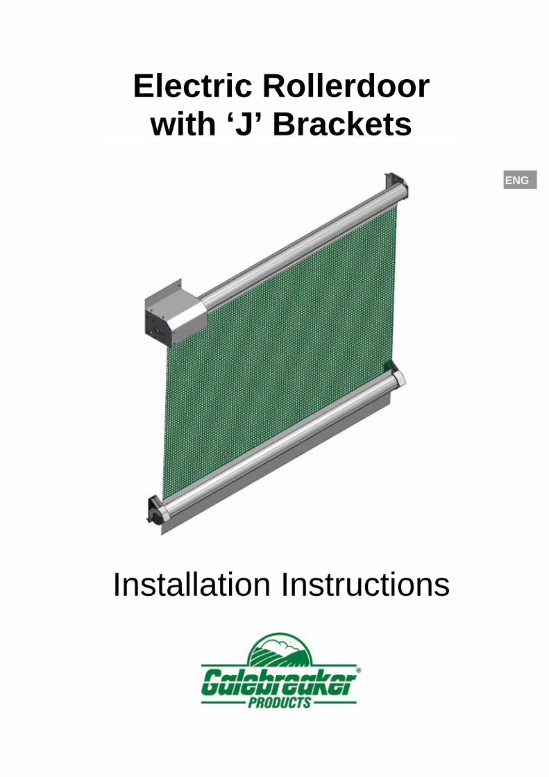
Electric Rollerdoor with ‘J’ Brackets
Installation Instructions
ENG

ELECTRIC ROLLERDOOR – J BRACKETS Introduction
-2-
Figure 1, System Overview and Individual Components

ELECTRIC ROLLERDOOR – J BRACKETS Introduction
-3-
ENG
INTRODUCTION
Parts List
REFERENCE QTY PRODUCT DESCRIPTION
A1 2 Top and Bottom Tubes B1 1 Screen Material C1 1 Bottom Flap D1 1 Doors Over 5.5m Width Small Safety Spring (Orange tag)E1 1 Doors Up to 5.0m Wide Free End bracket (with shaft) E2 1 Doors up to 5.0m: Free End Collar F1 1 Motor Bracket H1 1 30cm Cowling I1 1 Pair Cowling Pair of Ends J1 2 6mm Nylon Insert For Bottom Flap (not shown) K1 2 Insert Lockers L1 2 100mm J Bracket Guide M1 1 Left Hand 100mm Dia J Bracket Bzp M2 1 Right Hand 100mm Dia J Bracket Bzp N1 2 100mm Black Tube Cap/Insert O1 1 Electric Motor Assembly P1 1 Rotary Drive Switch - Optional
P2 1 Contactor Box and Drive Switches - Optional
Q1 1 80x80x5 Plastic Junction Box R1 8 M8x30 HT Set screw S1 10 M8 Nyloc Bzp T1 8 M4.2x19 Posi-Pan Self Drill Screws U1 4 M5.5x19 Hex Self Drill Coarse Screw V1 2 Nylon Cable Tie 150 x 3.6mm (not shown) X1 1 Wall Bracket Hole Template (not shown) Y1 1 140x45mm Yellow template (not shown)
Z1 2 M8x20 HT Set screw and Nut
Your Safety
The larger doors will require a mechanical lift to mount the roller assembly onto the top
brackets. The respective weights are given in the table below based on standard material. Add
5% to this figure for doors supplied with ‘HP’ fabric, and 15% for doors supplied with black
Stockscreen and solid fabrics.
WIDTH/HEIGHT 3.1m 4.1m 5.1m 2.5m 25kg 26kg 27kg 3.0m 27kg 28kg 29kg 3.5m 29kg 30kg 31kg 4.0m 32kg 33kg 34kg 4.5m 34kg 35kg 36kg 5.0m 36kg 37kg 38kg 5.5m 45kg 46kg ----- 6.0m 47kg 48kg -----
Table 1, Roller Assembly Weights

ELECTRIC ROLLERDOOR – J BRACKETS Introduction
-4-
ENG
Pre-Installation Check
Figure 2 indicates space required to install your door with additional information for
mounting multiple doors in series.
Order Width (m)
Fabric Width (m)
Order Height (m)
Max Height (m)
2.5 2.5 3.1 3.10 3.0 3.0 4.1 4.10 3.5 3.5 5.1 5.05 4.0 4.0 4.5 4.5 5.0 5.0 5.5 5.5 6.0 6.0
Figure 2, Fitting Requirements
Adjacent Systems
Top Brackets J Brackets

ELECTRIC ROLLERDOOR – J BRACKETS Introduction
-5-
ENG
CAUTION: To safeguard against any danger points, the minimum height ‘H’
of any door is 2.5m.
In the event of power or door failure, the door must not form the only means
of exit from the building to which it is fitted.
Wind Loadings The structure to which the door is fitted needs to be of adequate strength to resist the following wind loads.
Wind Speed (km/hr)
Wind Load (N)* Wind Load (Kg)*
70 = W x H x 233 = W x H x 24 100 = W x H x 481 = W x H x 49 140 = W x H x 933 = W x H x 95
*No allowance made for safety margins
Electrics
Only allow qualified electricians to work on the electrical connections of the door. This
document covers the key instructions with regards to bringing the Electric Drive into
service. Read the additional information from the supplier of the Electrical Motor and
Control Box for full installation instructions.
CAUTION: The power supply must be taken from a LOCKABLE isolation
switch positioned within 2m from the door.
Installer Competence
The installer should be able to demonstrate the required level of competence via
evidence of installing similar products or formal training. If competence cannot be
proven then they should not be allowed to install the product.
Product Description
The door is a power operated vertically moving rolling door comprising of a flexible
curtain capable of being rolled and for which the main intended uses are giving safe
access for goods and vehicles accompanied or driven by persons.

ELECTRIC ROLLERDOOR – J BRACKETS Introduction
-6-
ENG
Noise Levels
A-weighted sound pressure level (dB) 50
C-weighted sound pressure level (dB) 60
Items Required By The Installer
Standard tool kit comprising:
Electric drill
Angle grinder
Sharp pair of scissors or knife
Bolts for fixing the brackets to steel are supplied, if fixing to a wooden or
concrete building you will require eight M8 fasteners.
Key Instructions
CAUTION: Potentially hazardous situation: must be avoided otherwise
injuries may result.
ATTENTION: Observe the given instructions otherwise the product or
adjacent items may be damaged
NOTE: Helpful comments and information to assist in installation or use of
your product
NOTE: Before starting the installation it is advisable to read
these instructions completely to help understand the general
procedure and options available.
NOTE: Colour versions of the installation instructions can be
downloaded from our website:
www.galebreaker.com

ELECTRIC ROLLERDOOR – J BRACKETS Installation
-7-
ENG
INSTALLATION Door Assembly 1. Check the contents of your door against the parts list using Figure 1. Do not let
the screen material come into contact with any sharp objects or edges. The motor
can be mounted on either side of the top tube, for convenience the drawings
depict a door with the motor mounted on the left (Drive End = Left Hand Side).
2. Using the yellow template (X1), drill M8 holes for the two top brackets. The
maximum recommended overlap for Post Fixing (Drive End) = 120mm, Post
Fixing (Free End) = 100mm and for lintel fixing = 175mm (Figure 3). It is essential
that the top brackets are level and upright.
Figure 3, Top Bracket Positioning
ATTENTION: To prevent abrasion and material fray, maximum
overlap between bracket face and edge of fixing must not
exceed that shown in Figure 3. If overlap exceeds these
recommendations ensure there are no sharp objects on the
building to damage the material, and rough surfaces such as
concrete is protected with PVC strip or similar.
Drive End Free End
Post Fix
Lintel Fix

ELECTRIC ROLLERDOOR – J BRACKETS Installation
-8-
ENG
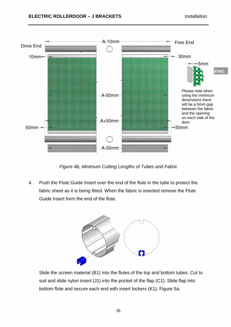
3. Cutting lengths (Figure 4):
Figure 4a, Standard Cutting Lengths of Tubes and Fabric
Top Tube = Distance between centre of drilled holes -10mm (-0.010m)
Screen and Flap = Distance between centre of drilled holes -90mm (-0.090m)
(80mm shorter than top tube)
Bottom Tube = Distance between centre of drilled holes +10mm (0.010m)
(20mm longer than top tube)
NOTE: Cutting details are for standard installation where there
are no constraints on fixing the top brackets or J brackets. It is
possible to reduce the distance between top brackets if there
are space constraints (Figure 4b). This configuration however
results in a 5mm gap between the fabric and the door opening
Drive End Free End
ELECTRIC ROLLERDOOR – J BRACKETS Installation
-9-
ENG
Figure 4b, Minimum Cutting Lengths of Tubes and Fabric
4. Push the Flute Guide Insert over the end of the flute in the tube to protect the
fabric sheet as it is being fitted. When the fabric is inserted remove the Flute
Guide Insert form the end of the flute.
Slide the screen material (B1) into the flutes of the top and bottom tubes. Cut to
suit and slide nylon insert (J1) into the pocket of the flap (C1). Slide flap into
bottom flute and secure each end with insert lockers (K1), Figure 5a.
Drive End Free End
Please note when using the minimum dimensions there will be a 5mm gap between the fabric and the opening on each side of the door

ELECTRIC ROLLERDOOR – J BRACKETS Installation
-10-
ENG
Figure 5a, Fabric Attached to Top and Bottom Tubes
Push end caps (N1) onto bottom tube making sure the drainage holes are located
vertically. Fix with two self-drilling screws (T1) to each cap
Figure 5b, Attach End Caps to Bottom Tube
i) Slide screen in to top tube
ii) Slide screen in to bottom tube
iii) Slide bottom flap in to bottom tube
Nylon Insert (J1) inserted into flap pocket
iv) Insert lockers (K1) used to locate bottom flap
Drainage holes located vertically

ELECTRIC ROLLERDOOR – J BRACKETS Installation
-11-
ENG
5. Roll the screen material fully onto the top tube, we recommend the fabric rolls off
the back of the top tube to minimise the gap between the fabric and building face.
Tie the tubes together as shown in Figure 6.
Figure 6, Roll Up Door Around Top Tube and Secure
6. Insert motor assembly into drive end of top tube, and then attach the drive end
wall bracket to the motor using the R-clip supplied, as shown in Figure 7.
Figure 7, Motor Inserted Into Top Tube and Drive Bracket Attached
Rope to tie tubes together
i) Slide motor (O1) into top tube
ii) Attach drive bracket (F1)
R-Clip

ELECTRIC ROLLERDOOR – J BRACKETS Installation
-12-
ENG
7.1. Doors up to 5.0m wide, Figure 8a:
Fasten the free end bracket (E1) to the holes drilled in building at free end, using
the M8 fixings supplied. Push free end collar (E2) into the top tube at the free
end. Lift the assembly into position and slide top tube onto free end bracket.
When in position fasten drive bracket (F1) and motor cowling bracket (G1) to
building.
Figure 8a, Mounting Doors Up to 5.0m Wide to Building
CAUTION: Referring to Table 1 on page 4, ensure the building
is of sound construction and that the most suitable type of
fastener is used. Use only M8 bolts or greater to fit these items
and ensure they are securely fastened to the building. Failure
of these fixings will result in your door falling off the building,
potentially injuring operators and bystanders.
7.2. Doors over 5.5m wide, Figure 8b:
Slide safety spring (D1) into the top tube, opposite end to the motor. Lift the
assembly into position, and bolt both brackets on using the M8 fixings supplied.
The motor cowling bracket (G1) is fastened to the drive end at the same time.
Motor Wire

ELECTRIC ROLLERDOOR – J BRACKETS Installation
-13-
ENG
Figure 8b, Attaching Doors Over 5.5m Wide to Building
Powering Motor
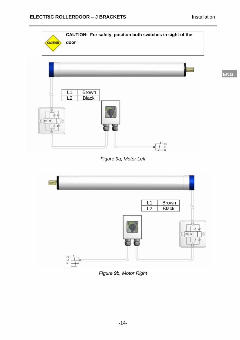
8. Single Switch Control
Following the Becker operation instructions, secure the junction box (R1), switch
(P1) and wires to the building. Ensure all wires exiting from the drive bracket,
junction box and switch point down to form a drip-loop so that rain water cannot
enter the motor or switch. To prevent entrapment by the lower tube, route the
cable to the back of the top bracket and fasten with cable-tie supplied (V1),
Figure 8b(iii). Ensure the cable glands are correctly seated to prevent water
ingress. Wire the 4-core motor cable into the junction box as detailed in Figure 9a
for left hand drive or Figure 9b for right hand drive.
To operate the door, rotate the switch in the direction you want the door to travel
as indicated by the arrows on the front panel. To stop the door at any position,
return the switch to position ’0’.
Motor Wire
i) Insert safety spring (D1) into top tube
ii) Fasten brackets to building
iii) Route motor wire
ELECTRIC ROLLERDOOR – J BRACKETS Installation
-14-
ENG
CAUTION: For safety, position both switches in sight of the
door
Figure 9a, Motor Left
Figure 9b, Motor Right
L1 Brown L2 Black
L1 Brown L2 Black

ELECTRIC ROLLERDOOR – J BRACKETS Installation
-15-
ENG
Double Control Switch
Secure the contactor box, secondary switches, and wires (P2) to the building.
Ensure all wires exiting from the drive bracket and motor switches point down to
form a drip-loop so that rain water cannot enter the motor or switches. To protect
the circuit board we advise the contactor box is mounted inside the building with
the glands face downwards. Ensure all cable glands are correctly seated to
prevent water ingress. Wire the 4-core motor cable into the contactor box (P2) as
detailed in Figure 9c. Re-fit lid checking that the seal is correctly seated to ensure
water does not damage the electronic controls. The switches operate in a ‘toggle’
fashion, i.e. with each press the motor will go one way, then stop, reverse, stop
again and so on.
Figure 9c, Contactor Box Wiring
CAUTION: For safety, position both switches in sight of the
door
Motor Left
Motor Right
Brown Black
Black Brown

ELECTRIC ROLLERDOOR – J BRACKETS Installation
-16-
ENG
ATTENTION: For maximum protection of the circuit board
inside the Contactor box, we advise this is mounted inside the
building away from direct rainfall. If outside operation is
required use the secondary switch for this location
‘J’ Bracket Installation
9. Fit one ‘J’ Bracket (M1) and Guide (L1) at the desired level with the M8 fixings
supplied (R1). Ensure there is 120mm clearance underneath for the tube to
engage into the bracket. Locate tube under bracket and at other end, rest
bracket over cap and press down until material is taut (Figure 10) and fix
bracket to building.
Figure 10, Attaching ‘J’ Bracket to Building
Setting Limit Switches
9. Follow the ‘Becker’ operation instructions to set the limit switches so that when
fully closed there should be just enough room above the bottom tube to locate in
the J Brackets.

ELECTRIC ROLLERDOOR – J BRACKETS Installation
-17-
ENG
Securing Fabric
10. Lower your door fully, centralise the screen and secure each corner using 19mm
self-drilling screws supplied (T1). It is important to tension sheet sideways before
fixing to remove creases (Figure 11).
Figure 11, Attaching J Bracket to Building
i) Tension fabric
iii) Secure corners of fabric, 4 locations
ii) Centralise door fabric

ELECTRIC ROLLERDOOR – J BRACKETS Installation
-18-
ENG
11. Attach the company detail label centrally to the front of the bottom tube.
Figure 12, Attaching Label
Installing Motor Cowling (Standard) or Door Cowling (Optional)
12. Fix the cowling end (G1) to the motor bracket using the M8x20 set screws (Z1)
and lock nuts (S1). Attach the motor cowling (H1) to the cowling end and to the
building at the free end using the screws (U1) as shown in Figure 13.
Figure 13, Motor Cowling Assembly

ELECTRIC ROLLERDOOR – J BRACKETS Installation
-19-
ENG
13. Door Cowling (Optional at extra cost)
REF: QTY PART DESCRIPTION CA1 * 1.75M Lengths of Cowling CB1 1 pr Cowling End CC1 2 M8x20 Hex bolt and Nut CD1 24 M4.8 x 8 St Steel Rivets / per join CE1 4 M5.5 x 19 Self Drilling Screws CF1 1 5mm Drill for rivets (not shown)
Figure 14, Door Cowling Assembly
C1. Fit the cowling ends (CB1) to the end brackets using the M8x20 bolts and nuts,
similar to that used at the drive end as shown above in Figure 17.
C2. Join the main cowling (CA1) with a minimum overlap of 265mm, using the M4.8 x
8 rivets, (CD1) 6 in each of the four faces. Fix the cowling to the cowling ends,
using the M5.5 x 19 self-drilling screws (CE1), three per side.
NOTE: The Cowling is self-supporting and does not require
intermediate brackets.

ELECTRIC ROLLERDOOR – J BRACKETS Installation
-20-
ENG
14. CE Marking Electrically Operated Products under Machinery Directive
It is the responsibility of the installer to check that the installation conforms to
the specific safety features detailed in the Manufacturer’s Installation
Instructions, to issue the CE Declaration of Conformity and mark a power
operated product under the Machinery Directive 2006/42/EC. To do this you will
require the following which should be delivered with the product:
1) This set of Installation Instructions (operating and maintenance instructions)
2) Maintenance Log Book, (including Installation Checklist and Customer Declaration of
Conformity)
3) 1 x Declaration of Conformity (Installer Copy) – to be completed
4) A CE Label
When CE marking a power operated Galebreaker product, it is vital to follow the
steps outlined below:
a) Install the product as per instructions, with no adaptations or modifications and
complete of the Health and Safety Checklist in the Maintenance Log Book.
b) Complete the two ‘Declarations of Conformity’ using the following:
Model Type: As shown on CE Label
Serial Number: As shown on CE Label
Installation Company: Your company name
Date Installed: Date Installed
Declaration made by: Responsible Person
Declaration and Instructions received by: Customer’s Signature
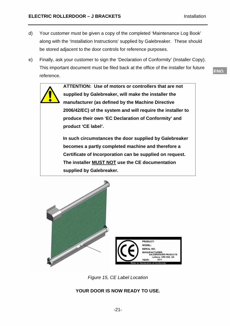
c) Fix the supplied CE label to the bottom tube. The label should be accessible /
visible. Where the serial number does not incorporate the door size, add the
Product width and Product height to the end of serial number using a permanent
marker pen. i.e. the full serial number should read
Serial Number: 1234 / RDE W X H
[W] Product Width (m)
[H] Product Height (m)
ELECTRIC ROLLERDOOR – J BRACKETS Installation
-21-
ENG
d) Your customer must be given a copy of the completed ‘Maintenance Log Book’
along with the ‘Installation Instructions’ supplied by Galebreaker. These should
be stored adjacent to the door controls for reference purposes.
e) Finally, ask your customer to sign the ‘Declaration of Conformity’ (Installer Copy).
This important document must be filed back at the office of the installer for future
reference.
ATTENTION: Use of motors or controllers that are not
supplied by Galebreaker, will make the installer the
manufacturer (as defined by the Machine Directive
2006/42/EC) of the system and will require the installer to
produce their own ‘EC Declaration of Conformity’ and
product ‘CE label’.
In such circumstances the door supplied by Galebreaker
becomes a partly completed machine and therefore a
Certificate of Incorporation can be supplied on request.
The installer MUST NOT use the CE documentation
supplied by Galebreaker.
Figure 15, CE Label Location
YOUR DOOR IS NOW READY TO USE.

ELECTRIC ROLLERDOOR – J BRACKETS Operation and Maintenance
-22-
ENG
OPERATION AND MAINTENANCE OF DOOR
How to use your door
From the open position, lower the bottom tube to beneath the ‘J’ brackets (M).
Backwind the motor to raise the bottom tube into the cup of the brackets. Continue to
operate the motor until the screen is taut and the motor cuts out.
To open, lower the bottom tube to beneath the ‘J’ brackets. Pull bottom tube clear of
‘J’ Brackets (M) and drive motor to raise door to upper limit of door.
CAUTION: Take care when operating the product on windy
days.
Important Safety Information
This door must only be operated by users familiar with its operation.
When operating the door do not place fingers near the 'J' brackets or other
moving parts at any time.
The person operating the door must have the door in sight at all times during its
operation.
Do not permit children to play with the door or its electrical controls.
Do not modify or attach any objects to the door as this may cause damage
and/or injury.
Operate the door only when properly adjusted and free from obstructions.
Should the door become difficult to operate or inoperable, consult your local
dealer. Repairs should only be carried out by competent personnel.
Maintenance of your door
Check annually for corrosion of the supporting bolts fixing the product to the
building, the bolt holding the shaft into the top brackets and the blind in general.
Replace suspect items to ensure it is safe for operators and bystanders alike
The safety spring (doors above 5.5m in width) has a design life of 10,000
operations, which equates to using the door approximately 3 times a day for 10

ELECTRIC ROLLERDOOR – J BRACKETS Operation and Maintenance
-23-
ENG
years. After 10 years we recommend a replacement spring be fitted, or following
the dismantling instructions given below remove the spring annually to ensure it
has not broken.
Should Screen material be damaged, repair with special repair kit (code SPS-99)
available from your Galebreaker dealer, importer or head office.
Keep the instructions supplied for reference purposes.
How to dismantle your door
Follow the installation instructions in reverse order.
CAUTION: For doors over 5.5m in width, ensure all spring
tension is removed before unbolting the top brackets to remove
the roller assembly and safety spring.
NOTE: This product has been tested to European Standard EN 12424
with a Resistance to Wind Load rating of Class 5. Tried and tested in the
harshest weather conditions, a summary of our guarantee is listed
below, see our website for full details:
Mechanical components: 100% guarantee for two years, followed
by an eight year graduated guarantee.
Electrical components: 100% guarantee for two years, followed
by a four year graduated guarantee.
RAIN INGRESS: Please note that in extreme weather conditions some
moisture will penetrate a mesh material.
Wind Load Resistance:
Mesh 75% Solid Up to 25sqm = Class 5
Solid Material Up to 25sqm = Class 5

Designed and Manufactured in the UK by GBR Industries Ltd.,
Original Instructions
© Copyright GBR Industries Ltd 2009. All Rights reserved
Model No: RDE/Mk1/12/04 Instruction Ver: 2012/04/ENG
Manufacturer: GBR Industries Ltd Tel: +44 (0) 1531 637 900
Galebreaker House Fax: +44 (0) 1531 637 901
New Mills Industrial Estate
Ledbury
Herefordshire, UK
HR8 2SS
www.galebreaker.com