
ELECTRIC MOTORS IN EXPLOSION-PROOF PROTECTION · PDF fileTotally enclosed standard induction...
43
ELECTRIC MOTORS IN EXPLOSION-PROOF PROTECTION INCREASED SAFETY EExe FLAMEPROOF ENCLOSURE EExd ISO 9001
Transcript of ELECTRIC MOTORS IN EXPLOSION-PROOF PROTECTION · PDF fileTotally enclosed standard induction...

ELECTRIC MOTORS IN EXPLOSION-PROOF PROTECTION
INCREASED SAFETY EExe FLAMEPROOF ENCLOSURE EExd
ISO 9001

ELECTRIC MACHINES
Three-phase induction electric motors, low voltage Totally enclosed and drip-proof standard induction single-speed and multi-speed electric motors with
squirrel cage rotor Totally enclosed and drip-proof standard induction electric motors with slipring rotor Totally enclosed standard induction electric motors with brake Totally enclosed standard induction electric motors in explosion-proof protection EExe and EExd Totally enclosed induction electric motors of marine design Specific-purpose electric motors
Single-phase induction electric motors Totally enclosed standard induction electric motors Specific-purpose induction electric motors for household appliances and other application
Micro-motors with squirrel cage rotor Three-phase induction electric motors of welded construction
Low voltage totally enclosed and drip-proof standard induction electric motors with squirrel cage rotor Low voltage totally enclosed and drip-proof special induction electric motors with squirrel cage or slipring rotor
Direct current electric motors Synchronous and asynchronous generators and converters Petrol and Diesel electric generating sets with induction and synchronus generators
GEAR MOTORS
Helical gear motors Helical shaft mounted gear motors Helical worm gear motors Variable speed drives Special purpose gear units
ELECTRONICS, REGULATION AND AUTOMATIC CONTROL
Power electronics Process eletronics and automatic control Low and medium voltage controls and devices
OTHER PROGRAMMS
Pumps and pumping systems Household appliances Service and repairing Machines and equipment for food industry and other processing industry Irrigation systems Engineering

CONTENTS
CONTENTS...............................................................................................................................................................1
1. GENERAL INFORMATION ...............................................................................................................................2
1.1 INTRODUCTION.............................................................................................................................................2 1.2 DESIGNATION OF DESIGN...........................................................................................................................2 1.3 STANDARDS AND DIRECTIVES ..................................................................................................................3
1.3.1 Review of basic standards and directives ..................................................................................... 3 1.3.2 Release, hazardous areas and zones........................................................................................... 4 1.3.3 Temperature classes and groups of gases ................................................................................... 4
1.4 MECHANICAL CHARACTERISTICS.............................................................................................................5 1.4.1 Mounting arrangements of electric motors .................................................................................... 5 1.4.2 Shaft extension ............................................................................................................................ 6 1.4.3 Balancing and vibrations .............................................................................................................. 6 1.4.4 Noise ........................................................................................................................................... 6 1.4.5 Surface protection ........................................................................................................................ 6 1.4.6 Rating plates ................................................................................................................................ 6
1.5 ELECTRICAL CHARACTERISTICS...............................................................................................................6 1.5.1 Voltage and frequency.................................................................................................................. 6 1.5.2 Terminals and winding connection................................................................................................ 7 1.5.3 Output.......................................................................................................................................... 7 1.5.4 Overloading and starting .............................................................................................................. 7 1.5.5 Insulation and heating .................................................................................................................. 7 1.5.6 Inverter fed motors ....................................................................................................................... 7
2. MOTORS IN PROTECTION OF INCREASED SAFETY EExe........................................................................8
2.1 EXPLOSION-PROOF PROTECTION OF INCREASED SAFETY EExe..........................................................8 2.2 DESIGN, TAKEOVER AND APPLICATION OF MOTORS IN PROTECTION EExe .....................................8
2.2.1 Design ......................................................................................................................................... 8 2.2.2 Overload protection...................................................................................................................... 8 2.2.3 Application ................................................................................................................................... 9 2.2.4 Technical acceptance and certification ......................................................................................... 9
2.3 MECHANICAL DESIGN .................................................................................................................................9 2.3.1 Mechanical protection................................................................................................................... 9 2.3.2 Tabular review of constructional materials .................................................................................... 9 2.3.3 Bearing arrangement.................................................................................................................... 9
2.4 TECHNICAL DATA FOR SELECTION ........................................................................................................11 2.6 PARTS ...........................................................................................................................................................19
3. MOTORS IN PROTECTION OF FLAMEPROOF ENCLOSURE EExd.........................................................22
3.1 EXPLOSION-PROOF PROTECTION FLAMEPROOF ENCLOSURE EExd..................................................22 3.2 DESIGN .........................................................................................................................................................23
3.2.1 Forms, mechanical protection, constructional characteristics and materials of electric motor EExd......................................................................................................................................... 23
3.2.2 Terminal box and assembly drawings......................................................................................... 23 3.2.3 Bearing arrangement.................................................................................................................. 28
3.3 TECHNICAL DATA FOR SINGLE-SPEED MOTORS SELECTION .............................................................29 3.4 TECHNICAL DATA FOR TWO-SPEED MOTORS SELECTION .................................................................31 3.5 OUTLINE DRAWINGS..................................................................................................................................32 3.6 PARTS ...........................................................................................................................................................40
4. QUESTIONNAIRE FOR EEx MOTORS ...........................................................................................................41

ELECTRIC MOTORS IN EXPLOSION-PROOF PROTECTION EExe and EExd 2
1. GENERAL INFORMATION
1.1 INTRODUCTION
Explosion-proof tree-phase induction electric motors in this catalogue, refer to the design of increased safety - EExe and flameproof enclosure - EExd. These motors are applied in industrial plants, in which danger can occur from explosion of inflammable vapours or gases (e.g. chemical industry, petrochemical industry, oil refinery, textile industry) and also in mines, which are dangerous because of methane and inflammable dust.
Design increased safety is in conformity with standards EN 50014 and EN 50019 while the design flameproof enclosure is in conformity with EN 50014 and EN 50018.
1.2 DESIGNATION OF DESIGN
Designation of electric motors manufactured by SEVER according to the mentioned designs is done as follows:
Marking EXAMPLE: Terminology to 94/ 9 / EC Reference EN 50014
Design increased safety - EExe
Design flameproof enclosure - EExd
el. motor for gear box
S 1 . Z K R 1 6 0 L - 2
number of polesstack length
shaft height (frame size) mm[ ]
squirrel cage motortotally enclosed design
flameproof enclosureseries
d
t ( )
number of polesstack length
shaft height (frame size) mm[ ]thermal protection
squirrel cage rotorel. motor for gear box
totally enclosed designincreased safety
series
temperaturegroup
Btemperature class
T 3
Ctemperature class
T 4
Atemperature class
T and T 1 2
1 . S Z K R T 1 6 0 L - 4 A( )

ELECTRIC MOTORS IN EXPLOSION-PROOF PROTECTION EExe and EExd 3
1.3 STANDARDS AND DIRECTIVES
1.3.1 Review of basic standards and directives
CE
I-
Ele
ctro
tech
nica
l co
mm
itte
e of
Ita
ly
CE
I 2-
3355
CE
I2 -6
CE
I 70
-151
9
CE
I 2/
No-
454
CE
I-U
NE
L 0
5513
CE
I 2-
8V1
No
5628
Dra
ft o
f It
alia
n st
anda
rd P
288
____
_
Dra
ft o
f It
alia
n st
anda
rd P
288
CE
I-U
NE
L 1
3117
CE
I 31
-845
9
CE
I 31
-147
2
____
_
BS-
Bri
tish
st
anda
rds
BS
4999
: P1
BS
4999
: P69
BS
4999
-34
BS
4999
: P20
BS
4999
: P21
BS
4999
: P22
BS
4999
: P23
BS
4999
: P51
____
_
BS
4999
: P50
BS
4999
: P10
BS
5501
: P1
BS
5501
: P5
BS
5501
: P6
Nat
iona
l sta
ndar
ds
DIN
/VD
E-
Ger
man
in
dust
ry n
orm
s-A
ssoc
iati
on o
f G
erm
an
elec
tric
tec
hnic
ians
D
IN E
N 6
0034
-1/
VD
E 0
530,
par
t 1
DIN
EN
600
34-2
/ V
DE
053
0, p
art 2
DIN
EN
600
34-5
/ V
DE
053
0, p
art 5
DIN
EN
600
34-6
/ V
DE
053
0, p
art 5
DIN
EN
600
34-7
/ V
DE
053
0, p
art 5
DIN
/VD
E 0
530,
par
t 8
DIN
EN
600
34-9
/ V
DE
053
0, p
art 9
DIN
/VD
E 0
530,
par
t 12
DIN
/VD
E 0
530,
par
t 14
DIN
ISO
237
3
DIN
426
73, p
art 3
DIN
EN
500
14
DIN
EN
500
18/
VD
E 0
171,
par
t 5
DIN
EN
500
19/
VD
E 0
171/
par
t 6
EN
-CE
NE
LE
C
Eur
opea
n co
mm
itte
e fo
r el
. tec
h.no
rms.
EN
600
34-1
EN
600
34-2
EN
600
34-5
EN
600
34-6
EN
600
34-7
EN
600
34-8
EN
600
34-9
EN
600
34-1
2
EN
600
34-1
4
EN
600
72
EN
500
14
EN
500
18
EN
500
19
Inte
rnat
iona
l ref
eren
t st
anda
rds
IEC
Int
erna
tion
al
Ele
ctro
tech
nica
l C
omm
issi
on
IEC
600
34,p
art 1
IE
C60
085
IEC
600
34, p
art 2
IEC
600
34, p
art 5
IEC
600
34, p
art 6
IEC
600
34, p
art 7
IEC
600
34, p
art 8
IEC
600
34, p
art 9
IEC
600
34, p
art 1
2
IEC
600
34, p
art 1
4
IEC
600
72
IEC
600
79, p
art 0
IEC
600
79, p
art 1
IEC
600
79, p
art 7
Rot
atin
g el
ectr
ical
mac
hine
s
Rot
atin
g el
ectr
ical
mac
hine
s, R
atin
g an
d pe
rfor
man
ces
Met
hods
for
det
erm
inin
g lo
sses
and
ef
fici
ency
Deg
ree
of m
echa
nica
l pro
tect
ion
Met
hods
of
cool
ing
Mou
ntin
g ar
rang
emen
ts
Ter
min
al m
arki
ngs
Noi
se li
mit
s va
lues
Star
ting
per
form
ance
s
Mec
hani
cal v
ibra
tion
s, li
mit
val
ues
Mou
ntin
g di
men
sion
s
Ele
ctri
cal a
ppar
atus
for
exp
losi
ve g
as
atm
osph
eres
- G
ener
al p
rovi
sion
s
Ele
ctri
cal a
ppar
atus
for
exp
losi
ve g
as
atm
osph
eres
- F
lam
e-pr
oof
encl
osur
e E
Exd
Ele
ctri
cal a
ppar
atus
for
exp
losi
ve g
as
atm
osph
eres
- in
crea
sed
safe
ty E
Exe
ELECTRIC MOTORS IN EXPLOSION-PROOF PROTECTION EExe and EExd 4
The explosion-proof protection motors covered by the new Directive 94/9/EC must also meet the requirements of other relevant Directives: Low Voltage Directive 73/23/EEC, modified by 93/68/EEC; Electromagnetic Compatibility Directive 89/336/EEC, modified by 92/31/EEC and 93/68/EEC and Machinery Directive 98/37/EC.
1.3.2 Release, hazardous areas and zones
The source of release is the place which contains inflammable medium or from which the inflammable medium goes out. Inflammable medium is considered to be, as follows:
♦ the explosive mixture of gases, vapours and dust, ♦ medium-air mixture can make explosive atmosphere. Regarding the way of formation and duration of explosive mixtures, sources of release are classified
as permanent, primary and secondary sources of release.
Permanent sources of release contain or emit permanently inflammable medium or explosive mixture into the surrounding space.
Primary sources of release, occasionally, at normal operation, contain or emit inflammable medium or mixture into the surrounding space.
Secondary sources of release, only under abnormal circumstances, i.e. in case of damage of the plant or incorrect technological process, emit inflammable medium or mixture into the surrounding space.
The sources of release can be multi-stage, and in determining hazardous area every stage will be taken into consideration separately.
The hazardous area is the space in which explosive atmosphere is present or can be expected. Its presence in the certain quantity requires special measures of precaution, with regard to assembly performance and use of electric devices, tools, machines and accessories which sparks, make electric arc or have heated surfaces.
Classification by group and category for mining and surface industry is defined according corresponding Standards and Directives.
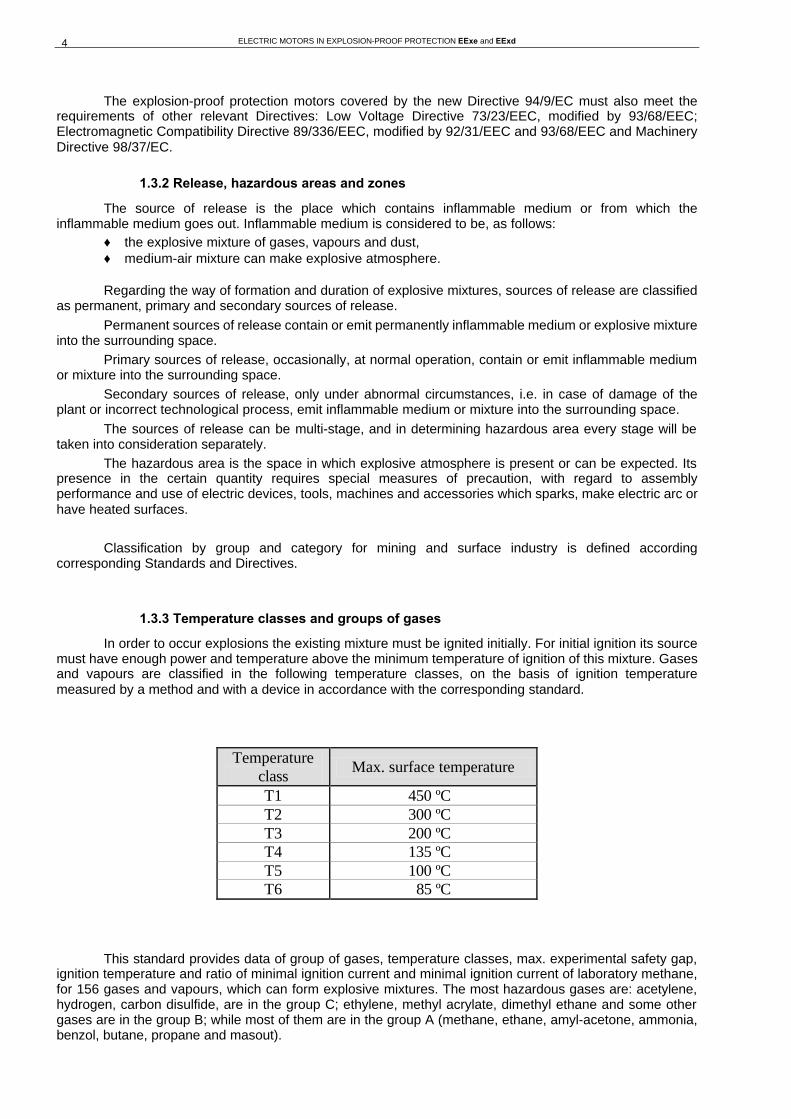
1.3.3 Temperature classes and groups of gases
In order to occur explosions the existing mixture must be ignited initially. For initial ignition its source must have enough power and temperature above the minimum temperature of ignition of this mixture. Gases and vapours are classified in the following temperature classes, on the basis of ignition temperature measured by a method and with a device in accordance with the corresponding standard.
Temperature class
Max. surface temperature
T1 450 ºC T2 300 ºC T3 200 ºC T4 135 ºC T5 100 ºC T6 85 ºC
This standard provides data of group of gases, temperature classes, max. experimental safety gap,
ignition temperature and ratio of minimal ignition current and minimal ignition current of laboratory methane, for 156 gases and vapours, which can form explosive mixtures. The most hazardous gases are: acetylene, hydrogen, carbon disulfide, are in the group C; ethylene, methyl acrylate, dimethyl ethane and some other gases are in the group B; while most of them are in the group A (methane, ethane, amyl-acetone, ammonia, benzol, butane, propane and masout).

ELECTRIC MOTORS IN EXPLOSION-PROOF PROTECTION EExe and EExd 5
1.4 MECHANICAL CHARACTERISTICS
1.4.1 Mounting arrangements of electric motors

ELECTRIC MOTORS IN EXPLOSION-PROOF PROTECTION EExe and EExd 6
1.4.2 Shaft extension
Motors are manufactured with one cylindrical shaft extension. On a special request, they can be manufactured also with two shaft extensions, with a tape shaft extension and with other special forms. The dimensions of shaft extension, keys and keyway dimensions are in conformity with the IEC 60072-1. The dimensions of tapped hole in shaft are shown in the following table. In order to keep load of bearings and of shaft extension within the allowed limits, there must be paid attention to radial and axial forces and to the type of transmission from a motor to a working machine.
Tapped hole in shaft Frame size Drive side Fan side
71 M5 M4 80 M6 M5 90 M8 M8
100 112
M10 M10
132 M12 M12 160 180
M16 M16
200 225 250 280 315
M20 M20
1.4.3 Balancing and vibrations
All motors are balanced dinamically with half key on a drive shaft extension in quality which corresponds to DIN ISO 2373. Measurement evaluation and limits of vibration are according to IEC 60034 part 14. The data are shown in the following table. Motors with vibration degree "R" (reduced) or "S" (special) are available on a special request.
Max. effective value of vibration speed for
shaft height H [mm]
Machines measured in a state of free suspension Rigid mounted Indicated speed
[mms-1] 56 ≤≤ H ≤≤ 132
[mm/s]
132 << H ≤≤ 225
[mm/s]
H >> 225
[mm/s]
H >> 400
[mm/s]
//600≤≤1800 >>1800≤≤3600
1,8 1,8
1,8 2,8
2,8 4,5
2,8 2,8
1.4.4 Noise
Motors satisfy the noise level emission in accordance to standard IEC 60034, Part 9.
1.4.5 Surface protection
Final surface protection of motor is performed by alkyd color, type RAL 7001. Motors for exploitation in special atmospheric conditions according to IEC 529 (EN 60529) are available on a special request.
1.4.6 Rating plates
Rated and inspection data are in the same rating plate fixed on the enclosure. A duplicate of the plate is located in the cover of the terminal box. The plates are made of stainless steel.
1.5 ELECTRICAL CHARACTERISTICS
1.5.1 Voltage and frequency
Motors are designed for rated voltage 400 V ±10%, 50 Hz according to IEC 60038. Motors up to 1,5 kW are connected in star (Y), and above that in delta (∆). On a special request motors can be designed for other voltages as well, as it is shown in the following table, up to 690 V and for frequency from 42 to 60 Hz.
ELECTRIC MOTORS IN EXPLOSION-PROOF PROTECTION EExe and EExd 7
Voltage [V] Frequency [Hz]
380 400 415 500
50
440 460 480
60
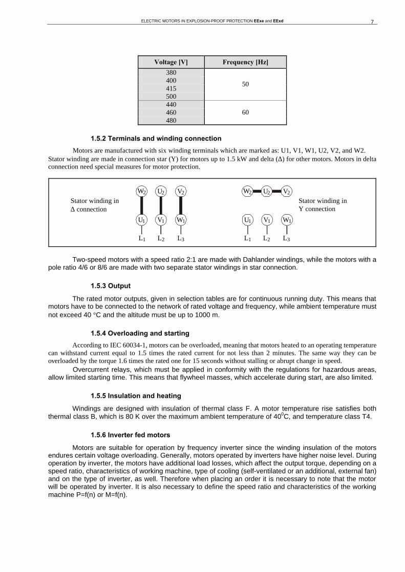
1.5.2 Terminals and winding connection
Motors are manufactured with six winding terminals which are marked as: U1, V1, W1, U2, V2, and W2. Stator winding are made in connection star (Y) for motors up to 1.5 kW and delta (∆) for other motors. Motors in delta connection need special measures for motor protection.
Two-speed motors with a speed ratio 2:1 are made with Dahlander windings, while the motors with a
pole ratio 4/6 or 8/6 are made with two separate stator windings in star connection.
1.5.3 Output
The rated motor outputs, given in selection tables are for continuous running duty. This means that motors have to be connected to the network of rated voltage and frequency, while ambient temperature must not exceed 40 °C and the altitude must be up to 1000 m.
1.5.4 Overloading and starting
According to IEC 60034-1, motors can be overloaded, meaning that motors heated to an operating temperature can withstand current equal to 1.5 times the rated current for not less than 2 minutes. The same way they can be overloaded by the torque 1.6 times the rated one for 15 seconds without stalling or abrupt change in speed.
Overcurrent relays, which must be applied in conformity with the regulations for hazardous areas, allow limited starting time. This means that flywheel masses, which accelerate during start, are also limited.
1.5.5 Insulation and heating
Windings are designed with insulation of thermal class F. A motor temperature rise satisfies both thermal class B, which is 80 K over the maximum ambient temperature of 400C, and temperature class T4.
1.5.6 Inverter fed motors
Motors are suitable for operation by frequency inverter since the winding insulation of the motors endures certain voltage overloading. Generally, motors operated by inverters have higher noise level. During operation by inverter, the motors have additional load losses, which affect the output torque, depending on a speed ratio, characteristics of working machine, type of cooling (self-ventilated or an additional, external fan) and on the type of inverter, as well. Therefore when placing an order it is necessary to note that the motor will be operated by inverter. It is also necessary to define the speed ratio and characteristics of the working machine P=f(n) or M=f(n).
U 1 V 1 W 1
U 2 V 2 W 2 U 2 V 2 W 2
L 1 L 2 L 3
U 1 V 1 W 1
Stator winding in ∆ connection
L 1 L 2 L 3
Stator winding in Y connection
ELECTRIC MOTORS IN EXPLOSION-PROOF PROTECTION EExe and EExd 8
2. MOTORS IN PROTECTION OF INCREASED SAFETY EExe
2.1 EXPLOSION-PROOF PROTECTION OF INCREASED SAFETY EExe
Concerning electric motors in explosion-proof protection of increased safety "EExe" there have been taken measures, which prevent occurrence of sparking, electric arcs or excessive temperatures during operation of machine.
2.2 DESIGN, TAKEOVER AND APPLICATION OF MOTORS IN PROTECTION EExe
2.2.1 Design
Electric motors are in an enclosure which protects against penetration of dust, particles and other impurities. Besides the enclosure, protection is consisted of:
♦ good insulating material (non-hygroscopic, thermostable, mechanically strong, non-flammable, self-extinguishing and resistant to leakage currents)
♦ good mechanical protection (terminal box IP54, enclosure IP44) ♦ allowed heating in the limits of temperature class T1 - T4; insulation class F (H class on a special
request) ♦ winding impregnation (vacuum system and submerging) ♦ expert supervision and handling
2.2.2 Overload protection
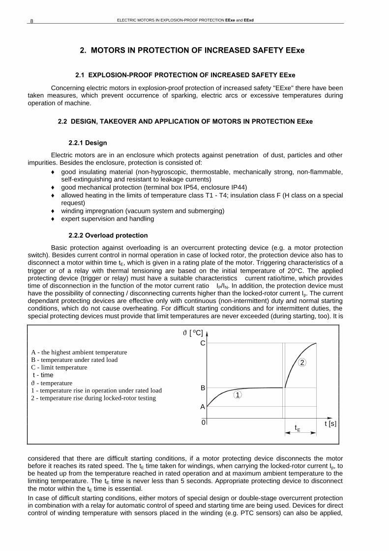
Basic protection against overloading is an overcurrent protecting device (e.g. a motor protection switch). Besides current control in normal operation in case of locked rotor, the protection device also has to disconnect a motor within time tE, which is given in a rating plate of the motor. Triggering characteristics of a trigger or of a relay with thermal tensioning are based on the initial temperature of 20°C. The applied protecting device (trigger or relay) must have a suitable characteristics ñ current ratio/time, which provides time of disconnection in the function of the motor current ratio ñ IP/IN. In addition, the protection device must have the possibility of connecting / disconnecting currents higher than the locked-rotor current Ip. The current dependant protecting devices are effective only with continuous (non-intermittent) duty and normal starting conditions, which do not cause overheating. For difficult starting conditions and for intermittent duties, the special protecting devices must provide that limit temperatures are never exceeded (during starting, too). It is
considered that there are difficult starting conditions, if a motor protecting device disconnects the motor before it reaches its rated speed. The tE time taken for windings, when carrying the locked-rotor current Ip, to be heated up from the temperature reached in rated operation and at maximum ambient temperature to the limiting temperature. The tE time is never less than 5 seconds. Appropriate protecting device to disconnect the motor within the tE time is essential. In case of difficult starting conditions, either motors of special design or double-stage overcurrent protection in combination with a relay for automatic control of speed and starting time are being used. Devices for direct control of winding temperature with sensors placed in the winding (e.g. PTC sensors) can also be applied,
A - the highest ambient temperature B - temperature under rated load C - limit temperature t - time ϑ - temperature 1 - temperature rise in operation under rated load 2 - temperature rise during locked-rotor testing
ϑ [ C]
0
A
B
C
o
t
2
1
Et [s]
ELECTRIC MOTORS IN EXPLOSION-PROOF PROTECTION EExe and EExd 9
but performance of such protection must be proved by testing together with a motor for all duty conditions (starting, continuous operation, disturbances, locked rotor). This is indicated in a suitable way.
In case of intermittent duty, heating is supervised by continuous secondary protection with two, three or more time constants, depending on the motor output.
2.2.3 Application
The motors can be applied in hazardous areas, where explosive atmosphere, such as mixtures of gases, fumes or vapour occur occasionally, but in accordance with temperature class rated in a motor rating plate. Valid technical regulations, which determine the installation of motor in hazardous areas, are to be paid attention.
2.2.4 Technical acceptance and certification
Technical acceptance and certification of motor in explosion-proof protection is performed according to defined procedures of authorized institutions and low regulations. SEVER has certified its products both in the Yugoslav authorized institution - FEDERAL INSTITUTION for STANDARDIZATION, Belgrade, and in Danish authorized institution DEMCO, Denmark.
2.3 MECHANICAL DESIGN
2.3.1 Mechanical protection
Motors are designed in mechanical protection IP55 (IEC 60034-5 and EN 60034-5).
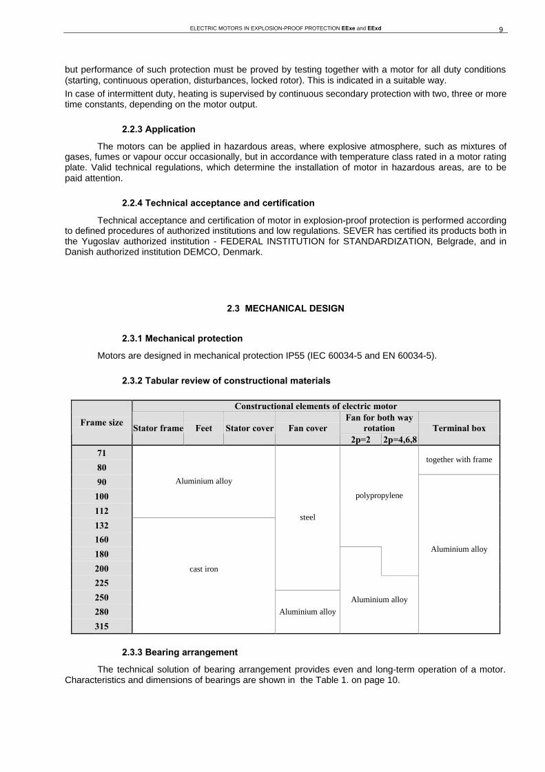
2.3.2 Tabular review of constructional materials
Constructional elements of electric motor Fan for both way
rotation Frame size
Stator frame Feet Stator cover Fan cover 2p=2 2p=4,6,8
Terminal box
71
80 together with frame
90
100
112
Aluminium alloy
132
160
polypropylene
180
200
225
steel
250
280
315
cast iron
Aluminium alloy
Aluminium alloy
Aluminium alloy
2.3.3 Bearing arrangement
The technical solution of bearing arrangement provides even and long-term operation of a motor. Characteristics and dimensions of bearings are shown in the Table 1. on page 10.
ELECTRIC MOTORS IN EXPLOSION-PROOF PROTECTION EExe and EExd 10
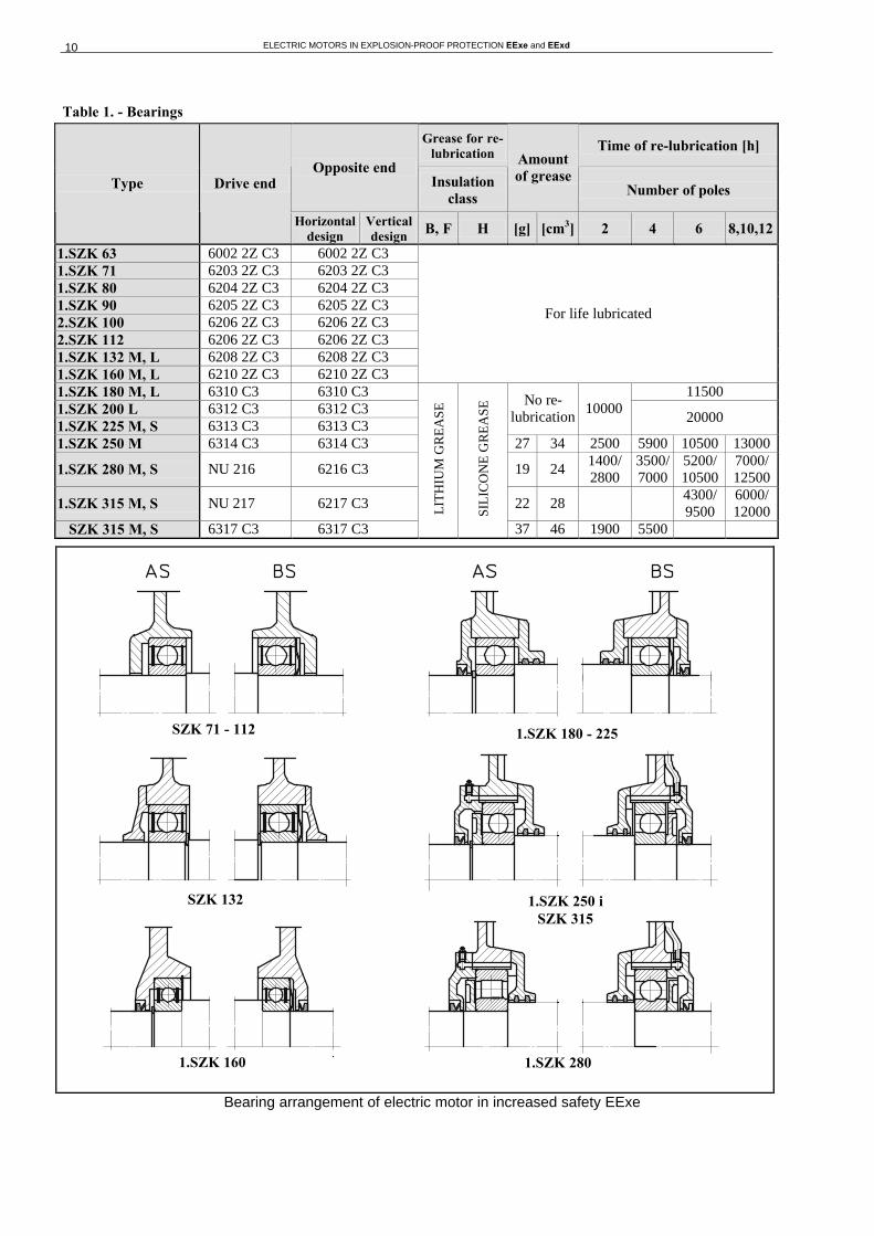
Table 1. - Bearings
Grease for re-lubrication Time of re-lubrication [h]
Opposite end Insulation
class
Amount of grease
Number of poles Type Drive end
Horizontal design
Vertical design B, F H [g] [cm3] 2 4 6 8,10,12
1.SZK 63 6002 2Z C3 6002 2Z C3 1.SZK 71 6203 2Z C3 6203 2Z C3 1.SZK 80 6204 2Z C3 6204 2Z C3 1.SZK 90 6205 2Z C3 6205 2Z C3 2.SZK 100 6206 2Z C3 6206 2Z C3
For life lubricated
2.SZK 112 6206 2Z C3 6206 2Z C3 1.SZK 132 M, L 6208 2Z C3 6208 2Z C3 1.SZK 160 M, L 6210 2Z C3 6210 2Z C3 1.SZK 180 M, L 6310 C3 6310 C3 11500 1.SZK 200 L 6312 C3 6312 C3 1.SZK 225 M, S 6313 C3 6313 C3
No re-lubrication
10000 20000
1.SZK 250 M 6314 C3 6314 C3 27 34 2500 5900 10500 13000
1.SZK 280 M, S NU 216 6216 C3 19 24 1400/ 2800
3500/ 7000
5200/ 10500
7000/ 12500
1.SZK 315 M, S NU 217 6217 C3 22 28 4300/ 9500
6000/ 12000
SZK 315 M, S 6317 C3 6317 C3
LIT
HIU
M G
RE
ASE
SIL
ICO
NE
GR
EA
SE
37 46 1900 5500
Bearing arrangement of electric motor in increased safety EExe
1.SZK 160
1.SZK 180 - 225
1.SZK 280
1.SZK 250 i SZK 315
SZK 132
SZK 71 - 112

ELECTRIC MOTORS IN EXPLOSION-PROOF PROTECTION EExe and EExd 11
2.4 TECHNICAL DATA FOR SELECTION
3000 min-1, 400 V, 50 Hz, Insulation class: F, Mechanical protection: IP 55, Temperature class: T1-T4.
Type Output [kW]
n [min-1]
ηη [%]
cos ϕϕ IN
[A] MN
[Nm] IP
IN
MP MN
Mm MN
tE [s]
KR
J [kgm2]
Mass [kg]
T1,T2 T3 T4 T1,T2 T3 T4 A-2A 0,37 0,37 - 2750 63 0,81 1,05 1,3 3,5 2,0 - 30 30 10 16 0,00023 5,4
A-2B 0,32 0,32 0,32 2760 63 0,82 0,90 1,1 3,8 2,3 - - 12 16 0,00023 5,4
B-2A 0,55 0,55 - 2760 69 0,81 1,43 1,9 4,2 2,2 - 18 18 9 16 0,00033 6,3 1.SZK 71
B-2B 0,42 0,42 0,42 2780 70 0,83 1,04 1,4 5,1 2,9 - - - 10 16 0,00033 6,3
A-2A 0,75 0,75 - 2770 72 0,80 1,87 2,6 4,8 2,3 - 20 20 9 16 0,00055 8,3
A-2B 0,62 0,62 0,62 2775 73 0,82 1,49 2,1 5,8 2,8 - - - 12 16 0,00055 8,3
B-2A 1,1 1,1 - 2770 73 0,84 2,58 3,8 4,7 2,3 - 18 12 6 16 0,00066 9,1 1.SZK 80
B-2B 0,8 0,8 0,8 2775 74 0,85 1,84 2, 5,9 3,1 - - - 9 16 0,00066 9,1
S-2A 1,3 1,3 - 2880 76 0,83 2,97 4,3 6,1 2,4 3,2 20 20 - 16 0,00154 13,4
S-2B 0,85 0,85 0,85 2905 77 0,83 1,92 2,8 6,6 2,7 3,2 25 25 14 16 0,00154 13,4
L-2A 1,85 1,85 - 2900 80 0,82 4,07 6,1 7,0 2,8 3,2 13 13 - 16 0,00216 16,4 SZK 90
L-2B 1,1 1,1 1,1 2915 79 0,82 2,45 3,6 7,2 3,0 3,6 24 24 14 16 0,00216 16,4
L-2A 2,5 2,5 - 2860 80 0,83 5,43 8,3 6,5 2,4 2,6 5 5 - 16 0,003 19 2.SZK 100
L-2B 1,6 1,6 1,6 2920 80 0,70 4,12 5,2 7,8 3,0 3,1 - - 5 16 0,003 19
M-2A 3,3 3,3 - 2885 84 0,86 6,60 10,9 7,6 3,2 3,3 10 10 - 16 0,005 24 2.SZK 112
M-2B 2,2 2,2 2,2 2925 79 0,80 5,03 7,2 8,5 3,5 3,8 - - 5 16 0,005 24
Sk-2B 4,6 4,6 - 2900 82 0,94 8,6 15,2 7,1 2,0 2,5 10 10 - 16 0,097 55
Sk-2C - - 3,3 2905 82 0,93 6,2 11 7,4 2,2 2,6 19 19 11 16 0,097 55
S-2A 6,5 - - 2900 82,5 0,94 12 21,4 7,3 2,1 2,6 9 - - 16 0,02 61,5
S-2B - 5,5 - 2900 82,5 0,94 10,3 18,1 7,4 2,1 2,6 9 9 - 16 0,02 61,5
SZK 132
S-2C - - 4 2905 83 0,93 7,5 13,1 7,5 2,3 2,8 18 18 10 16 0,02 61,5
Mk-2A 9,5 - - 2880 84,5 0,92 17,7 31,5 8,0 2,5 2,3 7 - - 13 0,021 89
Mk-2B - 7,5 - 2900 85 0,92 14,7 24,6 7,4 2,8 2,6 7 7 - 16 0,021 89
Mk-2C - - 5 2910 85 0,93 9,2 16,4 7,7 2,6 2,4 - - 7 13 0,021 89
M-2A 13 - - 2890 85,5 0,92 24 43,0 8,2 2,5 2,5 6 - - 13 0,028 108,5
M-2B - 10 - 2900 85,5 0,93 18,2 32,8 8,0 3,0 2,6 6 6 - 13 0,028 108,5
M-2C - - 6,5 2910 85,5 0,93 11,8 21,2 7,8 2,8 2,6 - - 6 13 0,028 108,5
L-2A 16 - - 2895 87 0,92 29 52,7 8,0 2,5 2,7 7 - - 13 0,034 113
L-2B - 12,5 - 2900 86,5 0,93 22,5 41,1 7,7 3,1 2,6 6 6 - 13 0,034 113
1.SZK 160
L-2C - - 8 2910 86,5 0,93 14,7 26,1 7,6 2,7 2,5 - - 6 13 0,034 113
M-2A 19 - - 2920 88,5 0,92 33,7 62,2 8,0 2,0 2,8 6,5 - - 10 0,057 138 SZK 180
M-2B - 15 - 2930 88 0,92 26,8 48,2 8,5 2,1 3,0 - 6,5 - 10 0,057 138
Lk-2A 25 - - 2935 90 0,87 46 81,4 6,5 1,7 2,5 10 - - 10 0,11 199,5
Lk-2B - 20 - 2945 89,5 0,87 37,1 64,9 8,3 1,7 2,7 - 8 - 10 0,11 199,5
L-2A 31 - - 2940 90,5 0,88 56,2 100,7 6,6 1,7 2,5 10 - - 10 0,13 215 1.SZK 200
L-2B - 24 - 2950 90 0,88 43,7 77,7 8,4 1,6 2,6 - 9 - 10 0,13 215
M-2A 38 - - 2960 92,2 0,89 67 123 7,5 1,8 2,9 11 - - 10 0,23 290 1.SZK 225
M-2B - 28 - 2960 91,5 0,89 50 90 7,8 1,8 2,9 14 10 - 10 0,23 290
M-2A 47 - - 2965 92,5 0,90 81,5 151 7,5 1,8 2,9 13 - - 10 0,36 395 1.SZK 250
M-2B - 36 - 2965 92,2 0,90 63 116 7,8 1,8 2,9 17 11 - 10 0,36 395
S-2A 64 - - 2970 93 0,91 109 206 7,8 1,6 2,6 14 - - 7 0,67 510
S-2B - 47 - 2970 92,8 0,91 81 151 8,2 1,7 2,6 17 13 - 7 0,67 510
M-2A 76 - - 2970 93,3 0,91 129 244 7,7 1,6 2,5 15 - - 7 0,81 600 1.SZK 280
M-2B - 58 - 2970 93 0,90 100 187 8,0 1,6 2,5 16 13 - 7 0,81 600
S-2A 95 - - 2981 93,5 0,92 159 304 7,7 1,4 2,7 16 - - 7 1,55 810
S-2B - 68 - 2983 93,2 0,91 116 218 8,2 1,5 2,7 20 15 - 7 1,55 810
M-2A 112 - - 2982 94 0,92 187 359 7,8 1,3 2,7 15 - - 7 1,8 890 SZK 315
M-2B - 80 - 2985 93,6 0,91 136 256 8,4 1,4 2,8 19 15 - 7 1,8 890
Note: Electric motors of frame size 355 and over on a special request !

ELECTRIC MOTORS IN EXPLOSION-PROOF PROTECTION EExe and EExd 12
1500 min-1, 400 V, 50 Hz, Insulation class: F, Mechanical protection: IP 55, Temperature class: T1-T4.
Type Output [kW]
n [min-1]
ηη [%]
cos ϕϕ IN
[A] MN
[Nm] IP
IN
MP MN
Mm MN
tE
[s] KR
J [kgm2]
Mass [kg]
T1,T2 T3 T4 T1,T2 T3 T4
A-4A 0,25 0,25 0,25 1345 63 0,76 0,75 1,77 3,2 1,7 1,9 60 60 30 13 0,00038 5,3
A-4B 0,22 0,22 0,22 1370 62 0,74 0,69 1,53 3,3 1,8 2,0 - - 35 13 0,00038 5,3
B-4A 0,37 0,37 0,37 1370 66 0,75 1,07 2,58 3,5 2,0 2,1 50 50 20 13 0,00055 6,3 1.SZK 71
B-4B 0,32 0,32 0,32 1390 66 0,70 1,00 2,20 3,6 2,1 2,2 - - 25 13 0,00055 6,3
A-4A 0,55 0,55 0,55 1375 69 0,76 1,51 3,80 3,5 1,8 1,9 34,5 31 8 13 0,0009 8,2
A-4B 0,42 0,42 0,42 1410 73 0,65 1,28 2,84 3,6 1,9 2,0 - - 10 13 0,0009 8,2
B-4A 0,75 0,75 - 1375 71 0,75 2,02 5,20 3,7 2,0 2,1 22 22 10 13 0,0011 9,0 1.SZK 80
B-4B 0,7 0,7 0,7 1375 72 0,74 1,90 4,86 3,9 2,2 2,3 - - 12 13 0,0011 9,0
S-4A 1,0 1,0 - 1400 76 0,80 2,38 6,82 5,4 2,2 2,7 24 24 - 13 0,00247 13,2
S-4B 0,8 0,8 0,8 1400 76 0,82 1,85 5,46 5,3 2,2 2,6 30 30 15 13 0,00247 13,2
L-4A 1,35 1,35 - 1410 74 0,77 3,42 9,14 5,9 3,0 3,2 18 18 - 16 0,0034 16,9 SZK 90
L-4B 1,2 1,2 1,2 1420 80 0,81 2,67 8,07 6,6 2,4 3,5 27 27 6 16 0,0034 16,9
L-4A 2,0 2,0 - 1410 78 0,78 4,75 13,55 5,9 2,4 2,8 10 10 - 16 0,0054 20,5
L-4B 1,5 1,5 1,5 1435 78 0,65 4,27 9,88 5,6 2,8 2,9 - - 5 16 0,0054 20,5
Ld-4A 2,5 2,5 - 1410 75 0,77 6,27 16,93 6,2 2,7 2,9 10 10 - 16 0,0071 22,6 2.SZK 100
Ld-4B 1,7 1,7 1,7 1440 75 0,62 5,28 11,27 6,4 2,7 2,9 - - 5 16 0,0071 22,6
M-4A 3,6 3,6 - 1430 80 0,78 8,33 24,04 6,5 2,9 3,2 5 5 - 16 0,013 28,4 2.SZK 112
M-4B 2,4 2,4 2,4 1450 79 0,70 6,26 15,81 5,7 2,3 2,6 - - 5 16 0,013 28,4
S-4A 5 - - 1445 86,5 0,84 10,0 33,0 6,0 2,1 2,7 12 - - 16 0,035 61,5
S-4B - 5 - 1445 86,5 0,84 10,0 33,0 6,0 2,1 2,7 12 12 - 16 0,035 61,5
S-4C - - 3,5 1450 86,5 0,83 7 23,0 5,9 2,0 2,6 17 17 8 16 0,035 61,5
M-4A 6,8 - - 1445 87,0 0,85 13,3 45,0 6,0 2,2 2,8 14 - - 16 0,045 73
M-4B - 6,8 - 1445 87,0 0,85 13,3 45,0 6,5 2,6 2,8 14 14 - 16 0,045 73
SZK 132
M-4C - - 4,1 1450 87,0 0,84 8,1 27,0 5,9 2,0 2,6 21 21 10 16 0,045 73
M-4A 10 - - 1445 86 0,81 20,5 66,8 7,3 3,2 3,6 8 - - 16 0,055 89,5
M-4B - 10 - 1445 87 0,81 20,5 66,8 7,3 3,2 3,6 8 8 16 0,055 89,5
M-4C - - 6,4 1450 87 0,83 12,8 42,6 7,0 3,3 3,7 22 22 6 16 0,055 89,5
L-4A 13,5 - - 1445 88 0,83 26,7 90,2 6,5 3,1 3,6 8 - - 16 0,073 118
L-4B - 13,5 - 1445 88 0,83 26,7 90,2 6,5 3,1 3,6 8 8 - 16 0,073 118
1.SZK 160
L-4C - - 8,5 1450 88 0,84 16,6 56,6 6,0 3,2 3,7 23 23 7 16 0,073 118
M-4A 17 - - 1460 89 0,82 33,6 111 6,2 2,6 2,4 11 - - 16 0,086 140
M-4B - 15 - 1465 89 0,82 29,7 98 7,0 2,9 2,7 - 10 - 16 0,086 140
L-4A 20 - - 1460 90 0,82 39,1 131 6,2 2,6 2,4 11 - - 16 0,102 155 1.SZK 180
L-4B - 17,5 - 1465 90 0,82 34,2 114 7,0 2,9 2,7 - 10 - 16 0,102 155
L-4A 27 - - 1460 90,7 0,88 49,0 175 6,2 2,3 2,3 12 - - 16 0,27 230 1.SZK 200
L-4B - 24 - 1475 90,7 0,87 44,0 155 7,0 2,6 2,6 14 14 - 16 0,27 230
S-4A 33 - - 1475 92 0,88 59,0 214 7,6 1,8 2,7 11 - - 13 0,362 280
S-4B - 30 - 1480 92 0,87 54 194 8,4 2,0 3,0 - 11,5 - 13 0,362 280
M-4A 40 - - 1475 92,4 0,88 71 260 7,5 1,8 2,7 10 - - 13 0,442 320 1.SZK 225
M-4B - 36 - 1480 92,4 0,87 65 233 8,3 2,0 3,0 - 11 - 13 0,442 320
M-4A 50 - - 1480 92,5 0,89 88 323 6,4 2,2 2,6 7,5 - - 13 0,64 385 1.SZK 250
M-4B - 44 - 1485 92,8 0,89 77 283 7,3 2,5 3,0 - 8 - 13 0,64 385
S-4A 68 - - 1480 93,4 0,90 117 439 6,4 1,8 2,4 13 - - 13 1,1 525
S-4B - 58 - 1485 93,5 0,88 102 373 7,5 2,0 2,8 16 - 13 1,1 525
M-4A 80 - - 1480 93,8 0,90 137 516 6,6 1,8 2,5 16 - 13 1,31 603 1.SZK 280
M-4B - 70 - 1485 94 0,88 122 450 7,5 2,0 2,8 - 18 - 13 1,31 603
S-4A 100 - - 1488 94 0,90 188 611 5,8 1,6 2,3 12 - - 13 3,5 840
S-4B - 84 - 1488 94 0,88 155 708 6,7 1,8 2,7 - 14 - 13 3,5 840
M-4A 120 - - 1488 94 0,90 220 975 5,8 2,0 2,2 12 - - 13 3,875 915 SZK 315
M-4B - 100 - 1488 94 0,89 180 180 6,7 2,2 2,6 - 14 - 13 3,875 915
Note: Electric motors of frame size 355 and over on a special request !

ELECTRIC MOTORS IN EXPLOSION-PROOF PROTECTION EExe and EExd 13
1000 min-1, 400 V, 50 Hz, Insulation class: F, Mechanical protection: IP 55, Temperature class: T1-T4.
Type Output [kW]
n [min-1]
ηη [%]
cos ϕϕ IN
[A] MN
[Nm] IP
IN
MP MN
Mm MN
tE
[s] KR
J [kgm2]
Mass [kg]
T1,T2 T3 T4 T1,T2 T3 T4
A-6A 0,18 0,18 0,18 900 57 0,65 0,70 1,9 2,6 1,9 2,0 95 80 25 13 0,00055 6,1 1.SZK 71
B-6A 0,25 0,25 0,25 890 57 0,64 0,99 2,7 2,6 1,8 2,1 93 77 24 13 0,00071 6,8
A-6A 0,37 0,37 0,37 915 66 0,69 1,17 3,9 3,6 2,0 2,2 150 150 54 13 0,0018 9 1.SZK 80
B-6A 0,55 0,55 0,55 915 68 0,66 1,77 5,7 3,7 2,4 2,5 74 74 26,5 13 0,0024 11,6
S-6A 0,65 0,65 0,65 935 66 0,69 2,06 6,6 4,7 2,6 3,0 23 23 23 16 0,00247 13 SZK 90
L-6A 0,95 0,95 0,95 920 67 0,73 2,80 9,9 4,8 2,4 2,8 18 18 6 16 0,0034 16,3
L-6A 1,3 1,3 - 930 67 0,70 4,04 13,3 4,2 2,2 2,4 15 15 5 13 0,0054 20,5 2.SZK 100
L-6B 1,2 1,2 1,2 940 67 0,66 3,90 12,2 4,4 2,5 2,7 - - 7 13 0,0054 20,5
M-6A 1,9 1,9 - 920 78 0,76 4,63 19,7 4,8 2,5 2,9 10 10 - 16 0,012 27 2.SZK 112
M-6B 1,6 1,6 1,6 930 78 0,72 4,11 16,4 5,2 2,9 3,3 - - 7 16 0,012 27
S-6B 2,6 2,6 - 960 84 0,79 5,7 26 6,0 2,4 2,7 14 - - 16 0,035 57
S-6C - - 2,2 960 84 0,79 5,7 26 6,0 2,4 2,7 14 14 - 16 0,035 57
Mk-6B 3,5 3,5 - 950 86 0,80 7,3 36 6,4 2,5 2,8 13 13 - 16 0,0425 68
Mk-6C - - 3,0 950 86 0,80 6,3 30 6,6 2,7 3,1 14 14 6,5 16 0,0425 68
M-6B 4,8 4,8 - 955 87 0,81 9,9 49 6,4 2,2 2,6 9 9 - 16 0,05 75,5
SZK 132
M-6C - - 4,0 955 86 0,80 8,4 40 6,6 2,2 2,6 11 11 6 16 0,05 75,5
M-6B 6,6 6,6 - 950 84 0,78 14,5 66,4 6,5 2,0 2,4 16 16 - 16 0,049 90
M-6C - - 5,0 950 84 0,78 11 66,4 6,7 2,1 2,5 30 21 5,5 16 0,049 90
L-6B 9,7 9,7 - 950 86 0,78 21 97,5 6,9 2,2 2,5 15 - - 16 0,070 120 1.SZK 160
L-6C - - 7,0 950 86 0,78 15,2 97,5 7,3 2,3 2,6 15 8 6 16 0,070 120
1.SZK 180 L-6B 13,2 13,2 - 960 87,5 0,83 26,6 131 6,0 2,2 2,7 15 15 - 16 0,144 150
Lk-6B 16,5 16,5 - 970 89 0,83 32,3 163 6,5 2,0 2,7 14 14 - 13 0,225 205 1.SZK 200
L-6B 20 20 - 970 90 0,83 39 197 6,5 2,0 2,7 11 11 - 13 0,27 230
1.SZK 225 M-6B 27 27 - 975 91 0,84 51,3 265 6,5 2,0 2,7 19 19 - 13 0,656 330
1.SZK 250 M-6B 33 33 - 980 91 0,85 65 322 6,3 2,0 2,2 16 15 - 13 0,90 390
S-6B 40 40 - 985 92,5 0,87 72 388 7,3 2,4 2,7 14 14 - 13 1,5 500
M-6A 50 - - 986 92,9 0,88 89 484 7,1 2,3 2,7 - 13 - 13 1,82 560 1.SZK 280
M-6B - 46 - 987 92,8 0,87 82 445 7,7 2,5 2,8 15 - - 13 1,82 560
S-6A 68 - - 987 92,6 0,86 123 658 7,7 2,4 2,9 19 - - 13 2,7 730
S-6B - 64 - 988 92,7 0,86 116 619 8,2 2,6 3,1 - 13 - 13 2,7 730
M-6A 82 - - 986 93 0,88 145 794 7,6 2,3 2,9 18 - - 13 3,18 840 1.SZK 315
M-6B - 76 - 988 93 0,87 136 735 8,2 2,5 3,1 - 13 - 13 3,18 840 750 min-1, 400 V, 50 Hz, Insulation class: F, Mechanical protection: IP 55, Temperature class: T1-T4.
Type Output [kW]
n [min-1]
ηη [%]
cos ϕϕ IN
[A] MN
[Nm] IP
IN
MP MN
Mm MN
tE
[s] KR J
[kgm2] Mass [kg]
T1,T2 T3 T4 T1,T2 T3 T4
A-8A 0,09 0,09 0,09 670 43 0,50 0,60 1,28 2,2 1,8 2,0 55 55 22 16 0,00055 6,1 1.SZK 71
B-8A 0,12 0,12 0,12 680 46 0,50 0,75 1,68 2,0 1,9 2,2 25 25 13 16 0,00071 6,8
A-8A 0,18 0,18 0,18 680 55 0,55 0,86 2,53 2,8 2,2 2,5 30 30 15 16 0,0018 9 1.SZK 80
B-8A 0,25 0,25 0,25 690 57 0,56 1,13 3,46 2,8 2,3 2,5 35 35 15 16 0,0024 11,6
S-8A 0,37 0,37 0,37 700 66 0,65 1,24 5,05 3,5 2,0 2,2 55 55 20 16 0,00247 13 SZK 90
L-8A 0,5 0,5 0,5 700 69 0,67 1,56 6,82 4,0 2,8 2,8 75 75 50 16 0,0034 16,3
L-8A 0,65 0,65 0,65 700 64 0,62 2,36 8,87 3,7 2,0 2,4 20 20 10 13 0,0054 20,5 2.SZK 100
Ld-8A 0,95 0,95 0,95 680 64 0,65 3,30 13,34 3,5 2,1 2,4 20 20 10 13 0,0071 22,6
2.SZK 112 M-8A 1,3 1,3 1,3 700 71 0,67 3,94 17,74 3,6 2,0 2,2 25 25 10 13 0,012 27
S-8B 1,9 1,9 - 705 78 0,70 5 25,7 4,5 1,6 2,2 16 16 - 13 0,035 54 SZK 132
M-8AB 2,6 2,6 - 710 79 0,72 6,7 35,0 4,5 1,6 2,3 15 15 - 13 0,050 70,5
Mk-8B 3,5 3,5 - 710 78 0,68 9,5 47 4,5 1,9 2,2 14 14 - 13 0,037 87
M-8B 4,8 4,8 - 710 80 0,68 12,8 64,5 4,6 1,9 2,2 12 12 - 13 0,053 91,5 1.SZK 160
L-8B 6,6 6,6 - 710 82 0,69 16,8 89 4,6 1,9 2,2 11 11 - 13 0,076 122
1.SZK 180 L-8B 9,7 9,7 - 715 84 0,74 23 130 5,0 1,9 2,1 11 11 - 13 0,160 160
1.SZK 200 L-8B 13,2 13,2 - 720 87 0,73 30,5 175 5,0 1,8 2,2 10 10 - 13 0,225 205
S-8B 16,5 16,5 - 735 88,5 0,78 34,7 214 5,0 1,7 2,2 14 14 - 13 0,470 245 1.SZK 225
M-8B 20 20 - 735 89,5 0,78 42 260 5,0 1,7 2,2 15 15 - 13 0,560 285
1.SZK 250 M-8B 27 27 - 735 90 0,80 54 351 5,0 1,6 2,2 10 10 - 13 0,870 370
S-8B 33 33 - 740 91,5 0,80 65 426 6,1 1,7 2,2 18 18 - 13 1,5 495 1.SZK 280
M-8B 40 40 - 740 92 0,81 78 516 6,2 1,6 2,2 17 17 - 13 1,82 580
S-8B 50 50 - 740 92 0,82 96 645 6,5 1,7 2,4 16 16 - 10 2,56 750 1.SZK 315
M-8B 68 68 - 740 92,5 0,83 128 877 6,2 1,5 2,3 15 15 - 10 3,32 870
Note: Electric motors of frame size 355 and over on a special request !
ELECTRIC MOTORS IN EXPLOSION-PROOF PROTECTION EExe and EExd 14
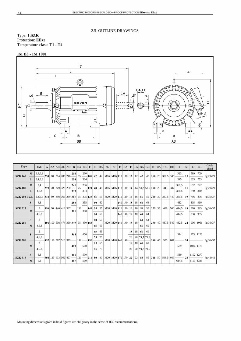
2.5 OUTLINE DRAWINGS Type: 1.SZK Protection: EExe Temperature class: T1 - T4 IM B3 - IM 1001
Type Pole A AA AB AC AD B BA BB C D DA d6 d7 E EA F FA GA GC H HA HC HD I K L LC Cable gland
M 2,4,6,8 210 260 323 589 709 1.SZK 160
L 2,4,6,8 254 60 314 285 246
254 65
304 108 42 42 M16 M16 110 110 12 12 45 45 160 23 300,5 345
345 15
633 753 Pg 29x29
M 2,4 241 296 351,5 652 772 1.SZK 180
L 4,6,8 279 70 349 323 260
279 75
334 121 48 48 M16 M16 110 110 14 14 51,5 51,5 180 28 343 387
370,5 15
690 810 Pg 29x29
1.SZK 200 Lk,L 2,4,6,8 318 80 398 369 289 305 95 375 133 55 55 M20 M20 110 110 16 16 59 59 200 30 387,5 440 395,5 19 756 876 Pg 36x37
S 4,8 286 355 60 60 140 140 18 18 64 64 432 805 960
2 55 55 110 110 16 16 59 59 414,5 800 925 1.SZK 225 M
4,6,8
356 90 446 418 337 311
110 380
149
60 60
M20 M20
140 140 18 18 64 64
225 35 438 500
444,5
19
830 985
Pg 36x37
S 2 60 60 64 64 1.SZK 250
M 4,6,8 406 100 508 474 360 349 95 430 168
65 65 M20 M20 140 140 18 18
69 69 250 40 487,5 549 482,5 24 906 1061 Pg 36x37
2 65 65 18 18 69 69 S
4,6,8 368 450
75 75 20 20 79,5 79,5 514 973 1128
2 65 65 18 18 69 69 1.SZK 280
M 4,6,8
457 110 567 510 379
419
112
500
190
75 75
M20 M20 140 140
20 20 79,5 79,5
280 45 535 607
539
24
1024 1179
Pg 36x37
S 6,8 406 500 589 1102 1277 1.SZK 315
M 6,8 508 125 633 562 427
457 120
550 216 80 80 M20 M20 170 170 22 22 85 85 315 50 598,5 669
614,5 28
1153 1328 Pg 42x42
Mounting dimensions given in bold figures are obligatory in the sense of IEC recommendations.

ELECTRIC MOTORS IN EXPLOSION-PROOF PROTECTION EExe and EExd 15
Type: 1.SZK Protection: EExe Temperature class: T1 - T4 IM B5, IM V1 - IM 3001, IM 3011
Type Pole Flange AC AD D DA d6 d7 E EA F FA GA GC HB I L LA LC M N P S Num.
of holes
T V Cable gland
Mk 2,4,6,8
M 2,4,6,8 323 589 709
1.SZK 160
L 2,4,6,8
FF 300 285 246 42 42 M16 M16 110 110 12 12 45 45 185
345 633
20
753
300 250 350 19 4 4 421 Pg 29x29
M 2,4 351,5 652 772 1.SZK 180
L 2,4,6 FF 300 325 260 48 48 M16 M16 110 110 14 14 51,5 51,5 207
370,5 690 20
810 300 250 350 19 4 5 435 Pg 29x29
1.SZK 200 Lk,L 2,4,6,8 FF 350 369 299 55 55 M20 M20 110 110 16 16 59 59 240 395,5 756 20 876 350 300 400 19 4 5 499 Pg 36x37
S 4,6,8 60 60 140 140 18 18 64 64 432 805 960
2 55 55 110 110 16 16 59 59 414,5 800 925 1.SZK225 M
4,6,8
FF 400 418 337
60 60
M20 M20
140 140 18 18 64 64
275
444,5 830
20
985
400 350 450 18 8 5 537 Pg 36x37
2 60 60 64 64 1.SZK 250 M
4,6,8 FF 500 471 360
65 65 M20 M20 140 140 18 18
69 69 299 482,5 906 22 1061 500 450 550 19 8 5 635 Pg 36x37
2 65 65 18 18 69 69 S
4,6,8 75 75 20 20 79,5 79,5 514 973 1128
2 65 65 18 18 69 69 1.SZK 280
M 4,6,8
FF 500 510 379
75 75
M20 M20 140 140
20 20 79,5 79,5
327
539,5 1024
22
1179
500 450 550 19 8 5 654 Pg 36x37
S 6,8 589 1102 1277 1.SZK 315
M 6,8 FF 600 562 427 80 80 M20 M20 170 170 22 22 85 85 344,5
614,5 1153 25
1328 600 550 660 24 8 6 757 Pg 42x42
Mounting dimensions given in bold figures are obligatory in the sense of IEC recommendations.

ELECTRIC MOTORS IN EXPLOSION-PROOF PROTECTION EExe and EExd 16
Type: .SZK Protection: EExe Temperature class: T1 - T4 IM B3 - IM 1001
Type Pole A AA AB AC AD B BA BB C D DA d6 d7 E EA F FA GA GC H HA HC HD HD* I K L LC Cable gland
1.SZK 71 2,4,6,8 112 35 142 139 - 90 33 114 45 14 11 M5 M5 30 23 5 4 16 12,5 71 10 139 - 191 120 7 241 267 Pg 13,5x13
1.SZK 80 2,4,6,8 125 41 155 157 - 100 40 130 50 19 14 M6 M6 40 30 6 5 21,5 16 80 11 156 - 210 140 10 271 304 Pg 13,5x13
S 100 130 156 300 356 SZK 90
L 2,4,6,8 140 40 180 178 -
125 40
155 56 24 24 M8 M8 50 50 8 8 27 27 90 15 178 - 250
168,5 10
325 381 Pg 13,5x13
L 2,4,6,8 2.SZK 100
Ld 4,8 160 44 204 198 - 140 48 175 63 28 28 M10 M10 60 60 8 8 31 31 100 16 198 - 274 193 12 370 438 Pg 13,5x13
2.SZK 112 M 2,4,6,8 190 46 236 222 - 140 48 175 70 28 28 M10 M10 60 60 8 8 31 31 112 20 222 - 311 200 12 377 445 Pg 21x20
Sk 2
S 2,4,6,8 140 180 239 441 529
M k 6 SZK132
M 2,4,6,8
216 55 271 260 214
178
52
218
89 38 38 M12 M12 80 80 10 10 41 41 132 22 261 307 -
258
12
479 567
Pg 21x20
2 65 65 140 140 18 18 69 69 - 559 1072 1232 S
4 598 447 406 150 500
80 80 170 170 22 22 85 85 615 705
- 589 1102 1292
2 65 65 140 140 18 18 69 69 - 584,5 1123 1283 SZK 315
M 4
508 125 633
598 447 457 150 550
216
80 80
M20 M20
170 170 22 22 85 85
315 50
615 705 - 614,5
28
1153 1343
Pg 42x42
Note: for frame size from 71 up to 112 terminal box is on the top,
for frame size from 132 up to 315 terminal box is on the right-hand side.
Mounting dimensions given in bold figures are obligatory in the sense of IEC recommendations.

ELECTRIC MOTORS IN EXPLOSION-PROOF PROTECTION EExe and EExd 17
Type: .SZK Protection: EExe Temperature class: T1 - T4 IM B5, IM V1 - IM 3001, IM 3011
Type Pole Flange AC AD D DA d6 d7 E EA F FA GA GC HB I L LA LC M N P S Num.
of holes
T V Cable gland
1.SZK 71 2,4,6,8 FF130 139 120 14 11 M5 M5 30 23 5 4 16 12,5 120 120 241 10 267 130 110 160 10 4 3,5 200 Pg 13,5x13
1.SZK 80 2,4,6,8 FF165 157 130 19 14 M6 M6 40 30 6 5 21,5 16 130 140 271 12 304 165 130 200 12 4 3,5 230 Pg 13,5x13
S 2,4,6,8 156 300 356 SZK 90
L 2,4,6,8 FF165 178 160 24 24 M8 M8 50 50 8 8 27 27 160
168,5 325 12
381 165 130 200 12 4 3,5 260 Pg 13,5x13
L 2,4,6,8 2.SZK 100
Ld 2,4,6 FF215 198 174 28 28 M10 M10 60 60 8 8 31 31 174 193 370 16 438 215 180 250 15 4 4 299 Pg 13,5x13
2.SZK 112 M 2,4,6,8 FF215 222 199 28 28 M10 M10 60 60 8 8 31 31 199 200 377 16 445 215 180 250 15 4 4 324 Pg 21x20
Sk 2
S 4,6,8 239 441 529
Mk 2 SZK 132
M 4,6,8
FF265 260 214 38 38 M12 M12 80 80 10 10 41 41 175
258 479
20
567
265 230 300 15 4 4 364 Pg 21x20
2 65 65 140 140 18 18 69 69 559 1072 1232 S
4 598 447
80 80 170 170 22 22 85 85 390
589 1102 1292 600 550 660 24 8 6 747
2 65 65 140 140 18 18 69 69 584,5 1123 1283 SZK 315
M 4
FF600
598 447 80 80
M20 M20
170 170 22 22 85 85 390
614,5 1153
25
1343 600 550 660 24 8 6 747
Pg 42x42
Mounting dimensions given in bold figures are obligatory in the sense of IEC recommendations.
ELECTRIC MOTORS IN EXPLOSION-PROOF PROTECTION EExe and EExd 18
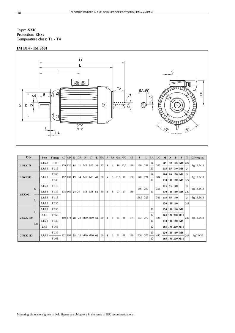
Type: .SZK Protection: EExe Temperature class: T1 - T4 IM B14 - IM 3601
Type Pole Flange AC AD D DA d6 d7 E EA F FA GA GC HB I L LA LC M N P S T Cable gland
2,4,6,8 F 85 8 85 70 105 M6 2,5 1.SZK 71
2,4,6,8 F 115 139 120 14 11 M5 M5 30 23 5 4 16 12,5 120 120 241
10 267
115 95 140 M8 3 Pg 13,5x13
F 100 8 100 80 120 M6 3 1.SZK 80 2,4,6,8
F 130 157 130 19 14 M6 M6 40 30 6 5 21,5 16 130 140 271
10 304
130 110 160 M8 3,5 Pg 13,5x13
2,4,6,8 F 115 115 95 140 3 S
2,4,6,8 F 130 156 300 356
130 110 160 3,5 Pg 13,5x13
2,4,6,8 F 115
178 169 24 24 M8 M8 50 50 8 8 27 27 160
168,5 325
10
381 115 95 140
M8
3 Pg 13,5x13 SZK 90
L 2,4,6,8 F 130 130 110 160 3,5
2,4,6,8 F 130 10 130 110 160 M8 L
2,4,6 F 165 12 165 130 200 M10
2,4,6,8 F 130 10 130 110 160 M8 2.SZK 100
Ld 2,4,6 F 165
198 174 28 28 M10 M10 60 60 8 8 31 31 174 193 370
12
438
165 130 200 M10
3,5 Pg 13,5x13
F 130 10 130 110 160 M8 2.SZK 112 2,4,6,8
F 165 222 199 28 28 M10 M10 60 60 8 8 31 31 199 200 377
12 445
165 130 200 M10 3,5 Pg 21x20
Mounting dimensions given in bold figures are obligatory in the sense of IEC recommendations.

ELECTRIC MOTORS IN EXPLOSION-PROOF PROTECTION EExe and EExd 19
2.6 PARTS
PARTS OF ELECTRIC MOTORS MOTOR TYPE: SZK 132-160
ITEM DESCRIPTION
1.1 STATOR - SET IM B3 1.2 STATOR - SET IM B5 2.1 ROTOR - SET 2.2 ROTOR KEY 3.0 TERMINAL BOX - SET 3.1 EARTH TERMINAL 3.2 TERMINAL BOARD WITH ACCESSORIES (EExe) 3.3 GASKET FOR TERMINAL BOX FRAME 3.4 TERMINAL BOX FRAME 3.5 GASKET FOR TERMINAL BOX COVER 3.6 TERMINAL BOX COVER 3.7 CABLE GLAND 4.1 STATOR COVER - DRIVE SIDE (A) 4.2 STATOR COVER - FAN SIDE (B) 4.3 FLANGE 5.1 FAN 5.2 FAN COVER 6.1 RADIAL SHAFT SEAL 6.2 BEARING - DRIVE SIDE (A) 6.3 BEARING - FAN SIDE (B) 6.4 RESILIENT PRELOADING RING 6.5 CIRCLIP 6.6 BEARING COVER, EXTERNAL - DRIVE SIDE (A) 6.7 BEARING COVER, EXTERNAL - FAN SIDE (B)
ELECTRIC MOTORS IN EXPLOSION-PROOF PROTECTION EExe and EExd 20
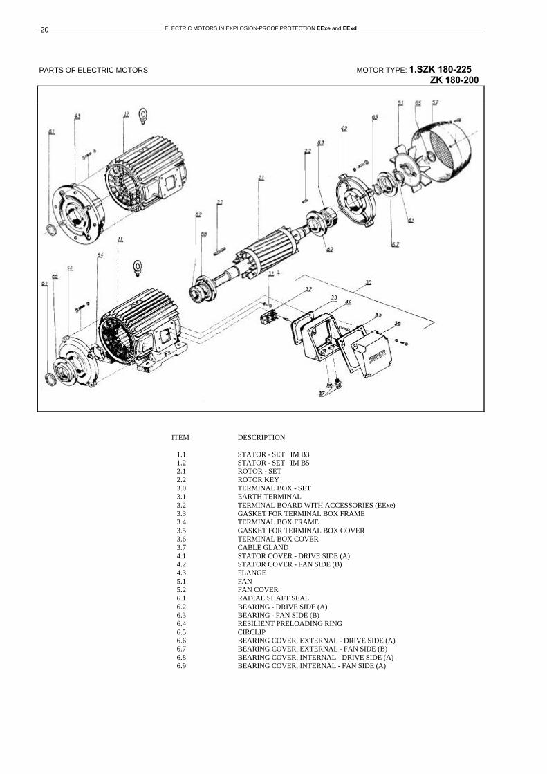
PARTS OF ELECTRIC MOTORS MOTOR TYPE: 1.SZK 180-225 ZK 180-200
ITEM DESCRIPTION 1.1 STATOR - SET IM B3 1.2 STATOR - SET IM B5 2.1 ROTOR - SET 2.2 ROTOR KEY 3.0 TERMINAL BOX - SET 3.1 EARTH TERMINAL 3.2 TERMINAL BOARD WITH ACCESSORIES (EExe) 3.3 GASKET FOR TERMINAL BOX FRAME 3.4 TERMINAL BOX FRAME 3.5 GASKET FOR TERMINAL BOX COVER 3.6 TERMINAL BOX COVER 3.7 CABLE GLAND 4.1 STATOR COVER - DRIVE SIDE (A) 4.2 STATOR COVER - FAN SIDE (B) 4.3 FLANGE 5.1 FAN 5.2 FAN COVER 6.1 RADIAL SHAFT SEAL 6.2 BEARING - DRIVE SIDE (A) 6.3 BEARING - FAN SIDE (B) 6.4 RESILIENT PRELOADING RING 6.5 CIRCLIP 6.6 BEARING COVER, EXTERNAL - DRIVE SIDE (A) 6.7 BEARING COVER, EXTERNAL - FAN SIDE (B) 6.8 BEARING COVER, INTERNAL - DRIVE SIDE (A) 6.9 BEARING COVER, INTERNAL - FAN SIDE (A)

ELECTRIC MOTORS IN EXPLOSION-PROOF PROTECTION EExe and EExd 21
PARTS OF ELECTRIC MOTORS MOTOR TYPE: 1.SZK 250-315
ITEM DESCRIPTION 1.1 STATOR - SET IM B3 1.2 STATOR - SET IM B5 2.1 ROTOR - SET 2.2 ROTOR KEY 3.0 TERMINAL BOX - SET 3.1 EARTH TERMINAL 3.2 TERMINAL BOARD WITH ACCESSORIES (EExe) 3.3 GASKET FOR TERMINAL BOX FRAME 3.4 TERMINAL BOX FRAME 3.5 GASKET FOR TERMINAL BOX COVER 3.6 TERMINAL BOX COVER 3.7 CABLE GLAND 4.1 STATOR COVER - DRIVE SIDE (A) 4.2 STATOR COVER - FAN SIDE (B) 4.3 FLANGE 5.1 FAN 5.2 FAN COVER 6.1 RADIAL SHAFT SEAL 6.2 BEARING - DRIVE SIDE (A) 6.3 BEARING - FAN SIDE (B) 6.4 RESILIENT PRELOADING RING 6.5 CIRCLIP 6.6 BEARING COVER, EXTERNAL - DRIVE SIDE (A) 6.7 BEARING COVER, EXTERNAL - FAN SIDE (B) 6.8 BEARING COVER, INTERNAL - DRIVE SIDE (A) 6.9 BEARING COVER, INTERNAL - FAN SIDE (B) 6.10 GREASE QUANTITY REGULATOR - DRIVE SIDE (A) 6.11 GREASE QUANTITY REGULATOR - FAN SIDE (B) 6.12 RE-GREASING DEVICE
ELECTRIC MOTORS IN EXPLOSION-PROOF PROTECTION EExe and EExd 22
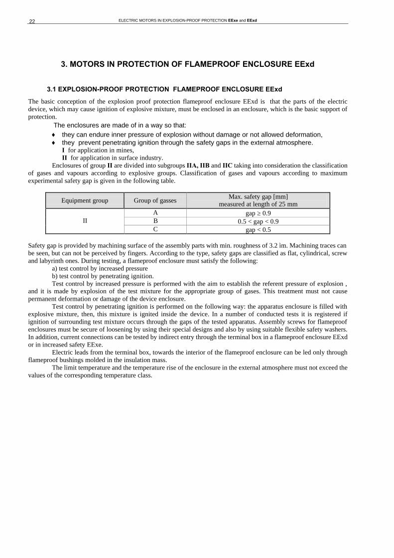
3. MOTORS IN PROTECTION OF FLAMEPROOF ENCLOSURE EExd
3.1 EXPLOSION-PROOF PROTECTION FLAMEPROOF ENCLOSURE EExd
The basic conception of the explosion proof protection flameproof enclosure EExd is that the parts of the electric device, which may cause ignition of explosive mixture, must be enclosed in an enclosure, which is the basic support of protection.
The enclosures are made of in a way so that: ♦ they can endure inner pressure of explosion without damage or not allowed deformation, ♦ they prevent penetrating ignition through the safety gaps in the external atmosphere.
I for application in mines, II for application in surface industry.
Enclosures of group II are divided into subgroups IIA, IIB and IIC taking into consideration the classification of gases and vapours according to explosive groups. Classification of gases and vapours according to maximum experimental safety gap is given in the following table.
Equipment group Group of gasses Max. safety gap [mm]
measured at length of 25 mm A gap ≥ 0.9 B 0.5 < gap < 0.9 II C gap < 0.5
Safety gap is provided by machining surface of the assembly parts with min. roughness of 3.2 ìm. Machining traces can be seen, but can not be perceived by fingers. According to the type, safety gaps are classified as flat, cylindrical, screw and labyrinth ones. During testing, a flameproof enclosure must satisfy the following: a) test control by increased pressure b) test control by penetrating ignition. Test control by increased pressure is performed with the aim to establish the referent pressure of explosion , and it is made by explosion of the test mixture for the appropriate group of gases. This treatment must not cause permanent deformation or damage of the device enclosure. Test control by penetrating ignition is performed on the following way: the apparatus enclosure is filled with explosive mixture, then, this mixture is ignited inside the device. In a number of conducted tests it is registered if ignition of surrounding test mixture occurs through the gaps of the tested apparatus. Assembly screws for flameproof enclosures must be secure of loosening by using their special designs and also by using suitable flexible safety washers. In addition, current connections can be tested by indirect entry through the terminal box in a flameproof enclosure EExd or in increased safety EExe. Electric leads from the terminal box, towards the interior of the flameproof enclosure can be led only through flameproof bushings molded in the insulation mass. The limit temperature and the temperature rise of the enclosure in the external atmosphere must not exceed the values of the corresponding temperature class.
ELECTRIC MOTORS IN EXPLOSION-PROOF PROTECTION EExe and EExd 23
3.2 DESIGN
3.2.1 Forms, mechanical protection, constructional characteristics and materials of electric motor EExd
Explosion-proof protection flameproof enclosure EExd is realized by cylindrical and flat gaps, which meet the requirements of the standard IEC 60079-1/EN 50018/DIN EN50018/VDE 0171-5. Motors, type St 1.ZK.. are three phase induction squirrel cage electric motors, single or multi-speed, for mounting arrangements IMB3, IMB5, IMV3, IMV5 and IMV6 (IEC 60034-7, DIN 42950 04,64).Cooling system is IC 411 as per IEC 60034-6 and degree of mechanical protection is IP 54 as per IEC 60034-5, DIN IEC 60034-5/VDE 0530-5.The motors are designed for the following application fields:
a) mines, i.e. pit mining EExd I b) surface industry EExd II for:
-group of gases A, B, C and - temperature classes T1-T4 Electric motors are made with the insulation class F.
Materials for electric motors EExd
Electric motor parts
Fan cover Fan for both way rotation Terminal box Frame size
Stator frame Feet Stator cover Exd I Exd II Exd I Exd II Exd I Exd II
71 80 90
100 112 132 160 180 200
cast iron cast iron
225 250
steel
280 315
steel welded
cast iron steel
steel
cast iron al
umin
ium
allo
y cast iron
alum
iniu
m a
lloy
3.2.2 Terminal box and assembly drawings
Terminal box is designed in two versions: a) Terminal box in increased safety EExe (fig.2) is made of aluminium alloy and it is with an
interplate, where the outlet leads are molded in, and with a certified terminal board. Cable entries of a terminal box in explosion-proof protection EExe and EExd II are type Pg (DIN 46255).
b) Cast iron terminal box (fig.3) has two chambers, one of which is in protection EExd and the other
one is in protection EExe. Chambers are connected by three flameproof bushings. A certified cable gland with trumpet is fitted to the terminal box and this design is used with electric motors both for mines and for surface industry. This terminal box has three connections (flameproof bushings) and it is used only for motors with direct starting. On a special request, for electric motors in EExd I (for mines), the terminal box and the cable gland with trumpet can be protected with an additional shield, which protects the terminal box and the cable gland against mechanical damages.

ELECTRIC MOTORS IN EXPLOSION-PROOF PROTECTION EExe and EExd 24
Table for fig. 2.
Frame size a b c d e h Cable gland as per DIN 46255 *
Terminal board
** 71 and 80 90 36 - 14 66 62 Pg-13,5 KB1 Ex
90 and 100 104 36 - 14 73 84 Pg-13,5 KB1 Ex 112 and 132 128 42 - 21 92 94 Pg-21 KB2 Ex 160 and 180 148 55 - 30 105 105 Pg-29 KB3 Ex 200 and 225 170 70 - 38 120 110,5 Pg 36 KB4 Ex 250 and 280 200 70 - 38 135 128 Pg 36 KB4 Ex
315 250 80 - 43 165 142 Pg 42 KB5 Ex
Table for fig. 3.
Frame size a b c d e h Cable gland with
trumpet as per EN 50014 and EN 50018 *
Type of flameproof
bushing **
71 and 80 160 115 98 15 172 105 90 and 100 176 126 110 15 188 113
Re-13,5 PI 16
112 Re-16 132
200 138 126 19 208 115 Re-21
PI 25
160 and 180 230 156 150 24 256 117 Re-29 PI 63 200 and 225 276 176 181 34 313 135 Re 36 PI 100 250 and 280 377 226 247 34 380 186 Re 36 PI 160
315 422 270 283 41 330 197 Re 42 PI 250 All dimensions in millimeters.
Fig. 2. Fig. 3.

ELECTRIC MOTORS IN EXPLOSION-PROOF PROTECTION EExe and EExd 25
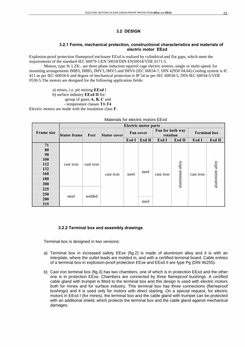
Assembly drawings - el.motor in explosion-proof protection, cast iron design with flameproof bushings, EExde I, EExde II B
Assembly drawings - el.motor in explosion-proof protection, cast iron design with molded outlet leads, EExde II B
ELECTRIC MOTORS IN EXPLOSION-PROOF PROTECTION EExe and EExd 26
Assembly drawings - el.motor in explosion-proof protection, cast iron design with molded outlet leads, EExde II C
Assembly drawings - el.motor in explosion-proof protection, welded design with flameproof bushings, EExde I, EExde II B
ELECTRIC MOTORS IN EXPLOSION-PROOF PROTECTION EExe and EExd 27
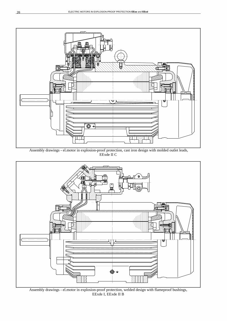
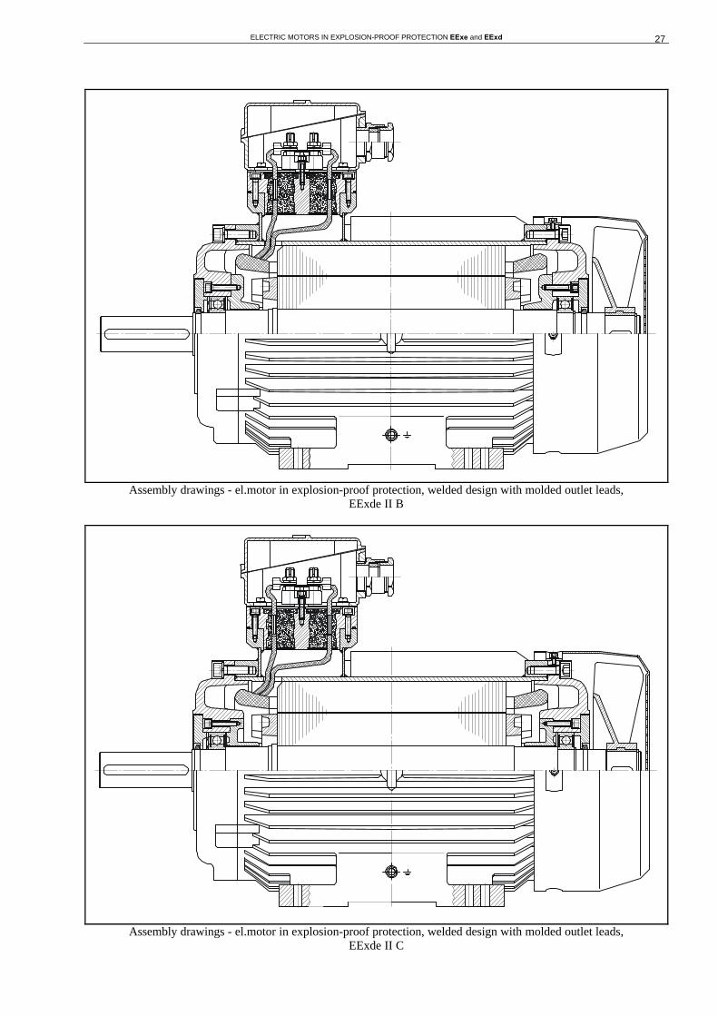
Assembly drawings - el.motor in explosion-proof protection, welded design with molded outlet leads, EExde II B
Assembly drawings - el.motor in explosion-proof protection, welded design with molded outlet leads, EExde II C

ELECTRIC MOTORS IN EXPLOSION-PROOF PROTECTION EExe and EExd 28
3.2.3 Bearing arrangement
Shaft of electric motor is arranged with roller bearings without possibility of re-lubrication. Motors of frame size 71 - 132 have non-fixed bearings on both sides, while the motors of frame size 160 - 315 have fixed fan side (BS) bearing and non-fixed drive side (AS) bearing. Types of bearings for normal duty conditions are given in the following table.
Frame size Num. of poles AS bearing BS bearing 71 2,4,6,8 6203 2Z 6203 2Z 80 2,4,6,8 6204 2Z 6204 2Z 90 2,4,6,8 6205 2Z 6205 2Z
100 2,4,6,8 6206 2Z 6206 2Z 112 2,4,6,8 6206 2Z 6206 2Z 132 2,4,6,8 6208 2Z 6208 2Z 160 2,4,6,8 6210 2Z 6210 2Z 180 2,4,6,8 6312 2Z 6312 2Z 200 2,4,6,8 6313 2Z 6313 2Z 225 2,4,6,8 6314 2Z 6314 2Z 250 2,4,6,8 6315 2Z 6315 2Z 280 2,4,6,8 6316 2Z 6316 2Z 315 2,4,6,8 6317 2Z 6317 2Z
Bearing arrangement of electric motors in flameproof enclosure EExde I, EExde IIB
Bearing arrangement of electric motors in flameproof enclosure EExde IIC
ELECTRIC MOTORS IN EXPLOSION-PROOF PROTECTION EExe and EExd 29
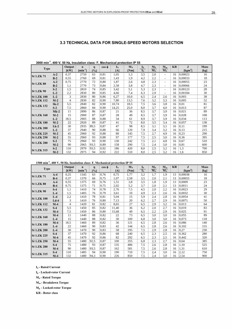
3.3 TECHNICAL DATA FOR SINGLE-SPEED MOTORS SELECTION
3000 min-1, 400 V, 50 Hz, Insulation class: F, Mechanical protection IP 55
Type Output [kW]
n [min-1]
ηη [%]
cos ϕϕ IN
[A] MN
[Nm] IP
IN
MP MN
Mm MN
KR
J [kgm4]
Mass [kg]
A-2 0,37 2750 63 0,81 1,05 1,3 3,5 2,0 - 16 0,00023 16 St 1.ZK 71
B-2 0,55 2760 69 0,81 1,43 1,9 4,2 2,2 - 16 0,00033 18 A-2 0,75 2770 72 0,80 1,87 2,6 4,8 2,3 - 16 0,00055 23
St 1.ZK 80 B-2 1,1 2770 73 0,84 2,58 3,8 4,7 2,3 - 16 0,00066 24 S-2 1,5 2810 74 0,85 3,42 5,1 5,3 2,3 - 16 0,00123 28
St 1.ZK 90 L-2 2,2 2830 80 0,85 4,66 7,4 6,3 2,9 - 16 0,00184 30
St 1.ZK 100 L-2 3 2830 80 0,86 6,27 10,0 6,5 2,4 2,6 16 0,003 38 St 1.ZK 112 M-2 4 2830 82 0,90 7,80 13,5 7,6 3,2 3,3 16 0,005 52
Sk-2 5,5 2840 82 0,90 10,74 18,5 7,5 3,6 3,8 16 0,01 81 St 1.ZK 132
S-2 7,5 2860 84 0,90 14,25 25,0 8,0 3,7 4,0 16 0,013 87 Mk-2 11 2890 86 0,87 21 36 8,5 3,7 3,9 16 0,021 89 M-2 15 2900 87 0,87 28 49 8,5 3,7 3,9 16 0,028 108 St 1.ZK 160 L-2 18,5 2905 88 0,88 34 61 8,9 3,7 3,9 16 0,034 113
St 1.ZK 180 M-2 22 2920 89 0,87 41 72 8,0 3,5 3,4 16 0,057 138 Lk-2 30 2935 89,5 0,87 47 98 8,5 3,1 3,1 16 0,11 199
St 1.ZK 200 L-2 37 2940 90 0,88 66 120 7,9 3,4 3,2 16 0,13 215
St 1.ZK 225 M-2 45 2960 92 0,88 80 145 7,5 2,7 4,9 16 0,23 290 St 1.ZK 250 M-2 55 2960 93 0,88 97 177 7,5 2,5 3,0 16 0,36 395
S-2 75 2960 93 0,90 130 242 7,5 2,1 4,8 16 0,67 510 St 1.ZK 280
M-2 90 2965 93,5 0,89 158 290 7,5 2,4 3,0 16 0,81 600 S-2 110 2970 93,5 0,92 186 420 8,0 2,5 3,2 16 1,3 700
St 1.ZK 315 M-2 132 2975 94 0,92 222 510 8,0 2,5 3,2 16 1,6 850
1500 min-1, 400 V, 50 Hz, Insulation class: F, Mechanical protection IP 55
Type Output [kW]
n [min-1]
ηη [%]
cos ϕϕ IN
[A] MN
[Nm] IP
IN
MP MN
Mm MN
KR J [kgm4]
Mass [kg]
A-4 0,25 1345 63 0,76 0,75 1,77 3,2 1,7 1,9 13 0,00038 16 St 1.ZK 71
B-4 0,37 1370 66 0,75 1,07 2,58 3,5 2,0 2,1 13 0,00055 18 A-4 0,55 1375 69 0,76 1,51 3,8 3,5 1,8 1,9 13 0,0009 23
St 1.ZK 80 B-4 0,75 1375 71 0,75 2,02 5,2 3,7 2,0 2,1 13 0,0011 24 S-4 1,1 1410 74 0,78 2,76 7,5 4,5 2,0 2,2 16 0,0023 29
St 1.ZK 90 L-4 1,5 1405 76 0,79 3,61 10 4,9 2,3 2,6 16 0,0032 30 L-4 2,2 1410 78 0,81 5,04 15 5,9 2,4 2,8 16 0,0054 41
St 1.ZK 100 Ld-4 3 1410 76 0,80 7,13 20 6,2 2,7 2,9 16 0,0071 50
St 1.ZK 112 M-4 4 1420 81 0,82 8,65 27 6,5 2,9 3,2 16 0,013 64 S-4 5,5 1450 85 0,82 11,40 36 6,2 2,0 2,7 16 0,019 83
St 1.ZK 132 M-4 7,5 1450 86 0,80 15,68 49 6,5 2,2 2,9 16 0,025 91 M-4 11 1440 88 0,82 22 73 6,5 3,0 3,0 16 0,055 89
St 1.ZK 160 L-4 15 1440 88 0,82 30 100 6,8 3,0 3,0 16 0,073 118 M-4 18,5 1460 89 0,82 36 121 6,5 2,8 2,6 16 0,086 140
St 1.ZK 180 L-4 22 1460 90 0,83 42 144 6,5 2,8 2,6 16 0,102 155
St 1.ZK 200 L-4 30 1470 90 0,83 58 195 7,5 2,9 2,8 16 0,27 230 S-4 37 1470 92 0,86 68 240 6,5 2,3 2,5 16 0,362 280
St 1.ZK 225 M-4 45 1470 92 0,86 82 292 6,5 2,3 2,5 16 0,442 320
St 1.ZK 250 M-4 55 1480 92,5 0,87 100 355 6,8 2,3 2,7 16 0,64 385 S-4 75 1480 93 0,87 135 486 7,5 2,6 2,8 16 1,10 525
St 1.ZK 280 M-4 90 1480 93,5 0,87 162 581 7,5 2,6 2,8 16 1,31 610 S-4 110 1485 94 0,90 190 710 7,5 2,4 3,0 16 2,12 750
St 1.ZK 315 M-4 132 1480 94,3 0,90 226 850 7,5 2,4 3,0 16 2,54 900
In - Rated Current
Ip - Locked-rotor Current
Mn - Rated Torque
Mm - Breakdown Torque
Mp - Locked-rotor Torque
KR - Rotor class

ELECTRIC MOTORS IN EXPLOSION-PROOF PROTECTION EExe and EExd 30
1000 min-1, 400 V, 50 Hz, Insulation class: F, Mechanical protection: IP 55
Type Output [kW]
n [min-1]
ηη [%]
cos ϕϕ IN
[A] MN
[Nm] IP
IN
MP MN
Mm MN
KR J [kgm4]
Mass [kg]
A-6 0,18 900 57 0,65 0,70 1,9 2,6 1,9 2,0 13 0,00055 18 St 1.ZK 71
B-6 0,25 890 57 0,64 0,99 2,7 2,6 1,8 2,1 13 0,00071 20 A-6 0,37 915 66 0,69 1,17 3,9 3,6 2,0 2,2 13 0,0018 24
St 1.ZK 80 B-6 0,55 915 68 0,66 1,77 5,7 3,7 2,4 2,5 13 0,0024 26 S-6 0,75 920 70 0,72 2,14 7,8 3,8 2,0 2,2 16 0,0037 29
St 1.ZK 90 L-6 1,1 920 70 0,70 3,33 11,2 3,8 2,2 2,4 16 0,0054 31
St 1.ZK 100 L-6 1,5 910 71 0,75 4,09 15,7 4,2 2,2 2,4 13 0,0054 41 St 1.ZK 112 M-6 2,2 925 76 0,75 5,61 22,7 4,8 2,5 2,9 16 0,012 58
S-6 3 945 81 0,76 7,03 30,3 4,5 2,0 2,4 13 0,015 77 Mk-6 4 950 82 0,77 9,12 40,2 4,5 1,9 2,0 13 0,02 85 St 1.ZK 132 M-6 5,5 950 83 0,77 12,35 55,3 4,5 1,9 2,1 13 0,028 96 M-6 7,5 950 84 0,78 16,5 75 5,5 2,0 2,4 16 0,049 90
St 1.ZK 160 L-6 11 950 86 0,78 24 110 6,0 2,2 2,5 16 0,070 120
St 1.ZK 180 L-6 15 960 87,5 0,83 29 149 6,0 2,2 2,7 16 0,144 150 Lk-6 18,5 970 89 0,83 36 182 6,5 2,0 2,7 16 0,225 205
St 1.ZK 200 L-6 22 970 90 0,83 43 417 6,5 2,0 2,7 16 0,27 230
St 1.ZK 225 M-6 30 975 91 0,84 57 494 6,5 2,0 2,7 16 0,656 330 St 1.ZK 250 M-6 37 980 91 0,85 69 361 6,0 2,0 2,2 13 0,9 390
S-6 45 982 92,5 0,87 82 438 6,9 2,4 2,8 16 1,5 500 St 1.ZK 280
M-6 55 985 93 0,87 98 533 6,9 2,3 2,6 16 1,82 560 S-6 75 985 93 0,87 135 727 7,5 2,4 2,7 16 2,7 750
St 1.ZK 315 M-6 90 985 93,5 0,88 159 872 7,5 2,4 2,7 16 3,2 900
750 min-1, 400 V, 50 Hz, Insulation class: F, Mechanical protection IP 55
Type Output [kW]
n [min-1]
ηη [%]
cos ϕϕ IN
[A] MN
[Nm] IP
IN
MP MN
Mm MN
KR J [kgm4]
Mass [kg]
A-8 0,09 670 43 0,50 0,60 1,28 2,2 1,8 2,0 16 0,00055 18 St 1.ZK 71
B-8 0,12 680 46 0,50 0,75 1,68 2,0 1,9 2,2 16 0,00071 20 A-8 0,18 680 55 0,55 0,86 2,53 2,8 2,2 2,5 16 0,0018 24
St 1.ZK 80 B-8 0,25 690 57 0,56 1,13 3,46 2,8 2,3 2,5 16 0,0024 26 S-8 0,37 700 59 0,62 1,45 5,05 2,9 1,9 2,0 13 0,0037 29
St 1.ZK 90 L-8 0,55 700 61 0,61 2,13 7,50 3,0 2,1 2,3 13 0,0054 31 L-8 0,75 690 64 0,67 2,52 10,4 3,7 2,0 2,4 13 0,0054 41
St 1.ZK 100 Ld-8 1,1 670 64 0,70 3,52 15,7 3,5 2,1 2,4 13 0,0071 50
St 1.ZK 112 M-8 1,5 680 70 0,71 4,37 21,0 3,6 2,0 2,2 13 0,012 58 S-8 2,2 705 76 0,69 6,08 29,8 3,6 1,6 2,0 13 0,015 77
St 1.ZK 132 M-8 3 710 79 0,69 7,89 40,4 3,5 1,6 1,9 13 0,028 96 Mk-8 4 690 78 0,68 10,8 54 4,7 2,1 2,4 13 0,037 87 M-8 5,5 700 79 0,68 14,7 74 4,7 2,1 2,4 13 0,053 91,5 St 1.ZK 160 L-8 7,5 710 81 0,70 19 101 4,9 2,1 2,4 13 0,076 122
St 1.ZK 180 L-8 11 715 84 0,74 25 148 4,8 2,1 2,3 13 0,16 160 St 1.ZK 200 L-8 15 720 87 0,73 34 199 5,5 2,0 2,4 13 0,225 205
S-8 18,5 735 88,5 0,78 39 240 5,3 1,9 2,4 13 0,47 245 St 1.ZK 225
M-8 22 735 89,5 0,77 45,5 286 5,3 1,8 2,5 13 0,56 285 St 1.ZK 250 M-8 30 735 90 0,80 61 390 5,5 1,8 2,4 13 0,87 370
S-8 37 735 92 0,80 72 481 5,6 1,8 2,2 13 1,5 495 St 1.ZK 280
M-8 45 735 92 0,81 87 585 5,6 1,8 2,2 13 1,82 580 S-8 55 740 92,5 0,82 104 710 7,1 2,0 3,0 13 2,56 750
St 1.ZK 315 M-8 75 740 93 0,83 141 970 6,6 1,8 4,8 13 3,32 870
In - Rated Current
Ip - Locked-rotor Current
Mn - Rated Torque
Mm - Breakdown Torque
Mp - Locked-rotor Torque
KR - Rotor class
ELECTRIC MOTORS IN EXPLOSION-PROOF PROTECTION EExe and EExd 31
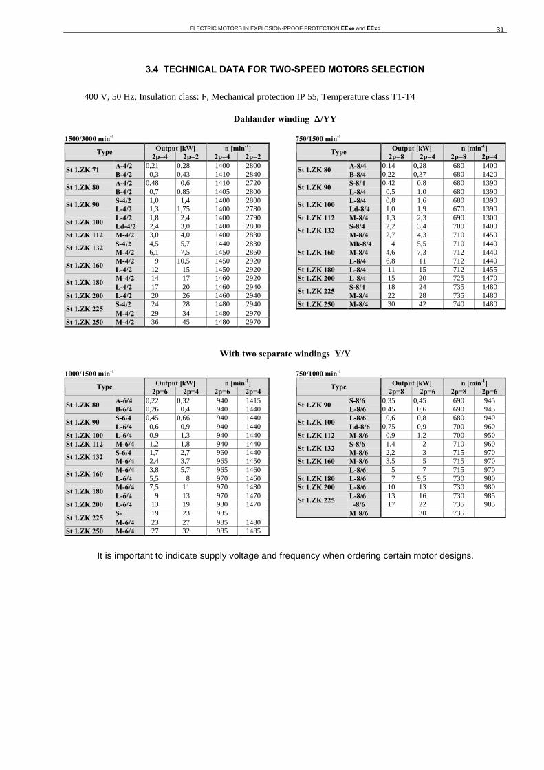
3.4 TECHNICAL DATA FOR TWO-SPEED MOTORS SELECTION
400 V, 50 Hz, Insulation class: F, Mechanical protection IP 55, Temperature class T1-T4
Dahlander winding ∆∆/YY
1500/3000 min-1 750/1500 min-1 Output [kW] n [min-1] Output [kW] n [min-1] Type
2p=4 2p=2 2p=4 2p=2 Type
2p=8 2p=4 2p=8 2p=4 A-4/2 0,21 0,28 1400 2800 A-8/4 0,14 0,28 680 1400
St 1.ZK 71 B-4/2 0,3 0,43 1410 2840
St 1.ZK 80 B-8/4 0,22 0,37 680 1420
A-4/2 0,48 0,6 1410 2720 S-8/4 0,42 0,8 680 1390 St 1.ZK 80
B-4/2 0,7 0,85 1405 2800 St 1.ZK 90
L-8/4 0,5 1,0 680 1390 S-4/2 1,0 1,4 1400 2800 L-8/4 0,8 1,6 680 1390
St 1.ZK 90 L-4/2 1,3 1,75 1400 2780
St 1.ZK 100 Ld-8/4 1,0 1,9 670 1390
L-4/2 1,8 2,4 1400 2790 St 1.ZK 112 M-8/4 1,3 2,3 690 1300 St 1.ZK 100
Ld-4/2 2,4 3,0 1400 2800 S-8/4 2,2 3,4 700 1400 St 1.ZK 112 M-4/2 3,0 4,0 1400 2830
St 1.ZK 132 M-8/4 2,7 4,3 710 1450
S-4/2 4,5 5,7 1440 2830 Mk-8/4 4 5,5 710 1440 St 1.ZK 132
M-4/2 6,1 7,5 1450 2860 M-8/4 4,6 7,3 712 1440 M-4/2 9 10,5 1450 2920
St 1.ZK 160 L-8/4 6,8 11 712 1440
St 1.ZK 160 L-4/2 12 15 1450 2920 St 1.ZK 180 L-8/4 11 15 712 1455 M-4/2 14 17 1460 2920 St 1.ZK 200 L-8/4 15 20 725 1470
St 1.ZK 180 L-4/2 17 20 1460 2940 S-8/4 18 24 735 1480
St 1.ZK 200 L-4/2 20 26 1460 2940 St 1.ZK 225
M-8/4 22 28 735 1480 S-4/2 24 28 1480 2940 St 1.ZK 250 M-8/4 30 42 740 1480
St 1.ZK 225 M-4/2 29 34 1480 2970
St 1.ZK 250 M-4/2 36 45 1480 2970
With two separate windings Y/Y
1000/1500 min-1 750/1000 min-1 Output [kW] n [min-1] Output [kW] n [min-1] Type
2p=6 2p=4 2p=6 2p=4 Type
2p=8 2p=6 2p=8 2p=6 A-6/4 0,22 0,32 940 1415 S-8/6 0,35 0,45 690 945
St 1.ZK 80 B-6/4 0,26 0,4 940 1440
St 1.ZK 90 L-8/6 0,45 0,6 690 945
S-6/4 0,45 0,66 940 1440 L-8/6 0,6 0,8 680 940 St 1.ZK 90
L-6/4 0,6 0,9 940 1440 St 1.ZK 100
Ld-8/6 0,75 0,9 700 960 St 1.ZK 100 L-6/4 0,9 1,3 940 1440 St 1.ZK 112 M-8/6 0,9 1,2 700 950 St 1.ZK 112 M-6/4 1,2 1,8 940 1440 S-8/6 1,4 2 710 960
S-6/4 1,7 2,7 960 1440 St 1.ZK 132
M-8/6 2,2 3 715 970 St 1.ZK 132
M-6/4 2,4 3,7 965 1450 St 1.ZK 160 M-8/6 3,5 5 715 970 M-6/4 3,8 5,7 965 1460 L-8/6 5 7 715 970
St 1.ZK 160 L-6/4 5,5 8 970 1460 St 1.ZK 180 L-8/6 7 9,5 730 980 M-6/4 7,5 11 970 1480 St 1.ZK 200 L-8/6 10 13 730 980
St 1.ZK 180 L-6/4 9 13 970 1470 L-8/6 13 16 730 985
St 1.ZK 200 L-6/4 13 19 980 1470 St 1.ZK 225
-8/6 17 22 735 985S- 19 23 985 M 8/6 30 735
St 1.ZK 225 M-6/4 23 27 985 1480
St 1.ZK 250 M-6/4 27 32 985 1485
It is important to indicate supply voltage and frequency when ordering certain motor designs.

ELECTRIC MOTORS IN EXPLOSION-PROOF PROTECTION EExe and EExd 32
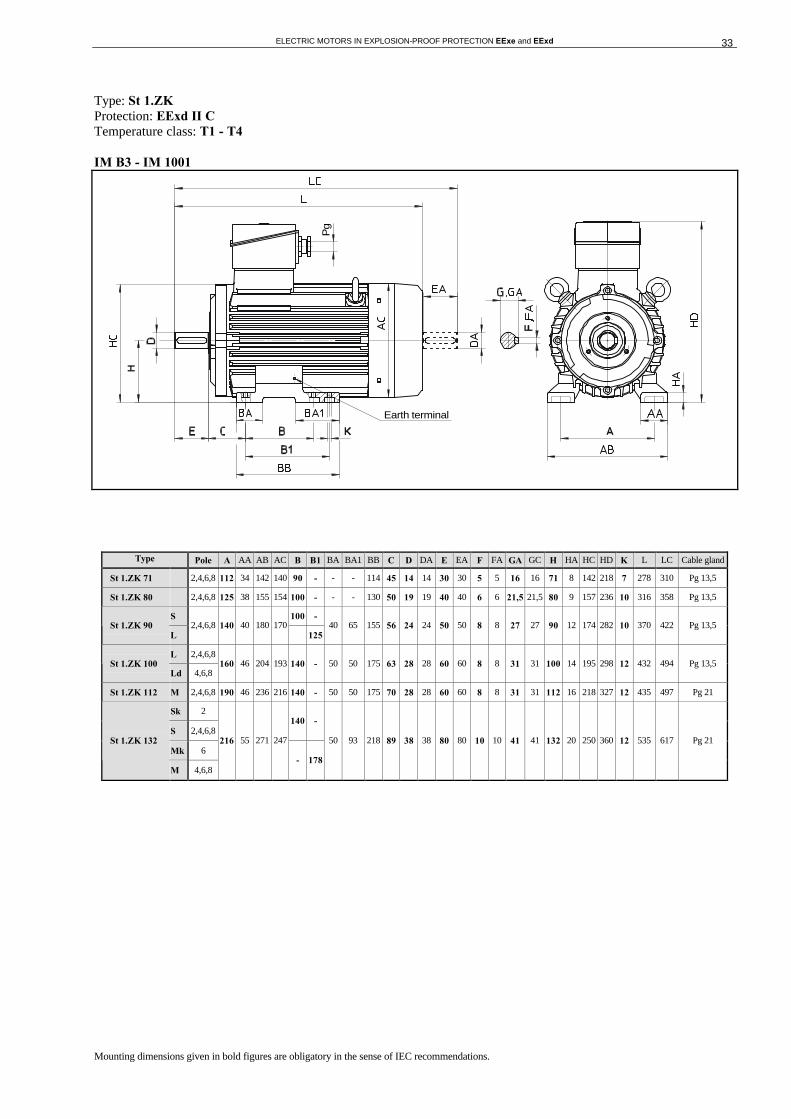
3.5 OUTLINE DRAWINGS
Type: St 1.ZK Protection: EExd I, EExde II B Temperature class: T1 - T4 IM B3 - IM 1001
Type Pole A AA AB AC B B1 BA BA1 BB C D DA E EA F FA GA GC H HA HC HD K L LC Cable gland with trumpet
St 1.ZK 71 2,4,6,8 112 34 142 140 90 - - - 114 45 14 14 30 30 5 5 16 16 71 8 142 242 7 278 310 Re 16
St 1.ZK 80 2,4,6,8 125 38 155 154 100 - - - 130 50 19 19 40 40 6 6 21,5 21,5 80 9 157 262 10 316 358 Re 16
S 100 - St 1.ZK 90
L 2,4,6,8 140 40 180 170
- 125 40 65 155 56 24 24 50 50 8 8 27 27 90 12 174 306 10 370 422 Re 16
L 2,4,6,8 St 1.ZK 100
Ld 4,6,8 160 46 204 193 140 - 50 50 175 63 28 28 60 60 8 8 31 31 100 14 195 326 12 432 494 Re 16
St 1.ZK 112 M 2,4,6,8 190 46 236 216 140 - 50 50 175 70 28 28 60 60 8 8 31 31 112 16 218 345 12 435 497 Re 21
Sk 2
S 2,4,6,8 140 -
Mk 6 St 1.ZK 132
M 4,6,8
216 55 271 247
- 178
50 93 218 89 38 38 80 80 10 10 41 41 132 20 250 378 12 535 617 Re 21
Mounting dimensions given in bold figures are obligatory in the sense of IEC recommendations.
Earth terminal
ELECTRIC MOTORS IN EXPLOSION-PROOF PROTECTION EExe and EExd 33
Type: St 1.ZK Protection: EExd II C Temperature class: T1 - T4 IM B3 - IM 1001
Type Pole A AA AB AC B B1 BA BA1 BB C D DA E EA F FA GA GC H HA HC HD K L LC Cable gland
St 1.ZK 71 2,4,6,8 112 34 142 140 90 - - - 114 45 14 14 30 30 5 5 16 16 71 8 142 218 7 278 310 Pg 13,5
St 1.ZK 80 2,4,6,8 125 38 155 154 100 - - - 130 50 19 19 40 40 6 6 21,5 21,5 80 9 157 236 10 316 358 Pg 13,5
S 100 - St 1.ZK 90
L 2,4,6,8 140 40 180 170
125 40 65 155 56 24 24 50 50 8 8 27 27 90 12 174 282 10 370 422 Pg 13,5
L 2,4,6,8 St 1.ZK 100
Ld 4,6,8 160 46 204 193 140 - 50 50 175 63 28 28 60 60 8 8 31 31 100 14 195 298 12 432 494 Pg 13,5
St 1.ZK 112 M 2,4,6,8 190 46 236 216 140 - 50 50 175 70 28 28 60 60 8 8 31 31 112 16 218 327 12 435 497 Pg 21
Sk 2
S 2,4,6,8 140 -
Mk 6 St 1.ZK 132
M 4,6,8
216 55 271 247
- 178
50 93 218 89 38 38 80 80 10 10 41 41 132 20 250 360 12 535 617 Pg 21
Mounting dimensions given in bold figures are obligatory in the sense of IEC recommendations.
Earth terminal
Pg

ELECTRIC MOTORS IN EXPLOSION-PROOF PROTECTION EExe and EExd 34
Type: St 1.ZK Protection: EExd I, EExde II B Temperature class: T1 - T4 IM B5 - IM 3001
Type Pole Flange AC AD D DA E EA F FA GA GC L LA LC M N P S Num.ofholes
T V Cable gland with trumpet
St 1.ZK 71 2,4,6,8 FF 130 140 171 14 14 30 30 5 5 16 16 278 12 310 130 110 160 10 4 3,5 251 Re 16
St 1.ZK 80 2,4,6,8 FF165 154 182 19 19 40 40 6 6 21,5 21,5 316 14 358 165 130 200 12 4 3,5 282 Re 16
S St 1.ZK 90
L 2,4,6,8 FF 165 170 216 24 24 50 50 8 8 27 27 370 16 422 165 130 200 12 4 3,5 316 Re 16
L 2,4,6,8 St 1.ZK 100
Ld 4,6,8 FF 215 193 226 28 28 60 60 8 8 31 31 432 18 494 215 180 250 15 4 4 351 Re 16
St 1.ZK 112 M 2,4,6,8 FF 215 216 233 28 28 60 60 8 8 31 31 435 18 497 215 180 250 15 4 4 358 Re 21
Sk 2
S 2,4,6,8
Mk 6 St 1.ZK 132
M 4,6,8
FF 265 247 246 38 38 80 80 10 10 41 41 535 18 617 265 230 300 15 4 4 396 Re 21
Mounting dimensions given in bold figures are obligatory in the sense of IEC recommendations.
Earth terminal

ELECTRIC MOTORS IN EXPLOSION-PROOF PROTECTION EExe and EExd 35
Type: St 1.ZK Protection: EExde II C Temperature class: T1 - T4 IM B5 - IM 3001
Type Pole Flange AC AD D DA E EA F FA GA GC L LA LC M N P S Num.of holes
T V Cable gland
St 1.ZK 71 2,4,6,8 FF 130 140 147 14 14 30 30 5 5 16 16 278 12 310 130 110 160 10 4 3,5 227 Pg 13,5
St 1.ZK 80 2,4,6,8 FF165 154 156 19 19 40 40 6 6 21,5 21,5 316 14 358 165 130 200 12 4 3,5 256 Pg 13,5
S St 1.ZK 90
L 2,4,6,8 FF 165 170 192 24 24 50 50 8 8 27 27 370 16 422 165 130 200 12 4 3,5 292 Pg 13,5
L 2,4,6,8 St 1.ZK 100
Ld 4,6,8 FF 215 193 198 28 28 60 60 8 8 31 31 432 18 494 215 180 250 15 4 4 323 Pg 13,5
St 1.ZK 112 M 2,4,6,8 FF 215 216 215 28 28 60 60 8 8 31 31 435 18 497 215 180 250 15 4 4 340 Pg 21
Sk 2
S 2,4,6,8
Mk 6 St 1.ZK 132
M 4,6,8
FF 265 247 228 38 38 80 80 10 10 41 41 535 18 617 265 230 300 15 4 4 378 Pg 21
Mounting dimensions given in bold figures are obligatory in the sense of IEC recommendations.
Earth terminal
Pg
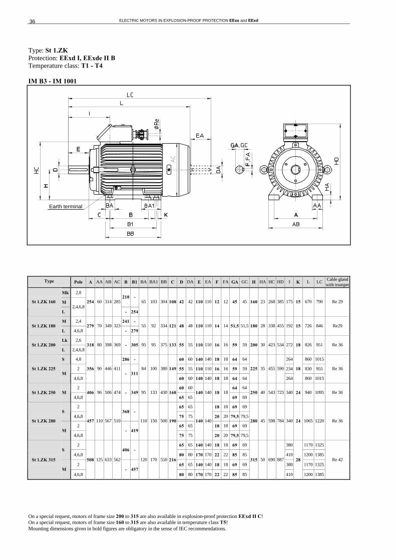
ELECTRIC MOTORS IN EXPLOSION-PROOF PROTECTION EExe and EExd 36
Type: St 1.ZK Protection: EExd I, EExde II B Temperature class: T1 - T4 IM B3 - IM 1001
Type Pole A AA AB AC B B1 BA BA1 BB C D DA E EA F FA GA GC H HA HC HD I K L LC Cable gland with trumpet
Mk 2,8
M 210 -
St 1.ZK 160
L 2,4,6,8
254 60 314 285
- 254
65 103 304 108 42 42 110 110 12 12 45 45 160 23 268 385 175 15 670 790 Re 29
M 2,4 241 - St 1.ZK 180
L 4,6,8 279 70 349 323
- 279 55 92 334 121 48 48 110 110 14 14 51,5 51,5 180 28 338 455 192 15 726 846 Re29
Lk 2,6 St 1.ZK 200
L 2,4,6,8 318 80 398 369 - 305 95 95 375 133 55 55 110 110 16 16 59 59 200 30 423 534 272 18 826 951 Re 36
S 4,8 286 - 60 60 140 140 18 18 64 64 264 860 1015
2 55 55 110 110 16 16 59 59 234 830 955 St 1.ZK 225 M
4,6,8
356 90 446 411 - 311
84 100 380 149
60 60 140 140 18 18 64 64
225 35 455 590
264
18
860 1015
Re 36
2 60 60 64 64 St 1.ZK 250 M
4,6,8 406 96 506 474 - 349 95 133 430 168
65 65 140 140 18 18
69 69 250 40 543 723 340 24 940 1095 Re 36
2 65 65 18 18 69 69 S
4,6,8 368 -
75 75 20 20 79,5 79,5
2 65 65 18 18 69 69 St 1.ZK 280
M 4,6,8
457 110 567 510
- 419
110 150 500 190
75 75
140 140
20 20 79,5 79,5
280 45 598 784 340 24 1065 1220 Re 36
2 65 65 140 140 18 18 69 69 380 1170 1325 S
4,6,8 406 -
80 80 170 170 22 22 85 85 410 1200 1385
2 65 65 140 140 18 18 69 69 380 1170 1325 St 1.ZK 315
M 4,6,8
508 125 633 562
- 457
120 170 550 216
80 80 170 170 22 22 85 85
315 50 690 887
410
28
1200 1385
Re 42
On a special request, motors of frame size 200 to 315 are also available in explosion-proof protection EExd II C! On a special request, motors of frame size 160 to 315 are also available in temperature class T5! Mounting dimensions given in bold figures are obligatory in the sense of IEC recommendations.
Earth terminal

ELECTRIC MOTORS IN EXPLOSION-PROOF PROTECTION EExe and EExd 37
Type: St 1.ZK Protection: EExde II B Temperature class: T1 - T4 IM B3 - IM 1001
Type Pole A AA AB AC B B1 BA BA1 BB C D DA E EA F FA GA GC H HA HC HD I K L LC Cable gland
Mk 2,8
M 210 -
St 1.ZK 160
L 2,4,6,8
254 60 314 285
- 254
65 103 304 108 42 42 110 110 12 12 45 45 160 23 268 385 175 15 650 770 Pg 29
M 2,4 241 - St 1.ZK 180
L 4,6,8 279 70 349 323
- 279 55 92 334 121 48 48 110 110 14 14 51,5 51,5 180 28 338 455 192 15 706 826 Pg 29
Lk 2,6 St 1.ZK 200
L 2,4,6,8 318 80 398 369 - 305 95 95 375 133 55 55 110 110 16 16 59 59 200 30 423 534 272 18 806 931 Pg 36
S 4,8 286 - 60 60 140 140 18 18 64 64 264 840 995
2 55 55 110 110 16 16 59 59 234 810 935 St 1.ZK 225 M
4,6,8
356 90 446 411 - 311
84 100 380 149
60 60 140 140 18 18 64 64
225 35 455 590
264
18
840 995
Pg 36
2 60 60 64 64 St 1.ZK 250 M
4,6,8 406 96 506 474 - 349 95 133 430 168
65 65 140 140 18 18
69 69 250 40 543 723 340 24 920 1075 Pg 36
2 65 65 18 18 69 69 S
4,6,8 368 -
75 75 20 20 79,5 79,5
2 65 65 18 18 69 69 St 1.ZK 280
M 4,6,8
457 110 567 510
- 419
110 150 500 190
75 75
140 140
20 20 79,5 79,5
280 45 598 784 340 24 1045 1200 Pg 36
2 65 65 140 140 18 18 69 69 380 1150 1305 S
4,6,8 406 -
80 80 170 170 22 22 85 85 410 1180 1365
2 65 65 140 140 18 18 69 69 380 1150 1305 St 1.ZK 315
M 4,6,8
508 125 633 562
- 457
120 170 550 216
80 80 170 170 22 22 85 85
315 50 690 887
410
28
1180 1365
Pg 42
On a special request, motors of frame size 200 to 315 are also available in explosion-proof protection EExd II C! On a special request, motors of frame size 160 to 315 are also available in temperature class T5! Mounting dimensions given in bold figures are obligatory in the sense of IEC recommendations.
Earth terminal
Pg

ELECTRIC MOTORS IN EXPLOSION-PROOF PROTECTION EExe and EExd 38
Type: St 1.ZK Protection: EExd I, EExde II B Temperature class: T1 - T4 IM B5 - IM 3001
Type Pole Flange AC AD D DA E EA F FA GA GC I L LA LC M N P S Num.of holes
T V Cable gland with trumpet
Mk 2,8
M St 1.ZK 160
L 2,4,6,8
FF 300 285 225 42 42 110 110 12 12 45 45 175 670 23 790 300 250 350 19 4 5 400 Re 29
M 2,4 St 1.ZK 180
L 4,6,8 FF 300 323 275 48 48 110 110 14 14 51,5 51,5 192 726 23 846 300 250 350 19 4 5 450 Re29
Lk 2,6 St 1.ZK 200
L 2,4,6,8 FF 350 369 334 55 55 110 110 16 16 59 59 272 826 23 951 350 300 400 19 4 5 534 Re 36
S 4,8 60 60 140 140 18 18 64 64 264 860 1015
2 55 55 110 110 16 16 59 59 234 830 955 St 1.ZK 225 M
4,6,8
FF 400 411 371
60 60 140 140 18 18 64 64 264 860
23
1015
400 350 450 18 8 5 596 Re 36
2 60 60 64 64 St 1.ZK 250 M
4,6,8 FF 500 474 473
65 65 140 140 18 18
69 69 340 940 25 1095 500 450 550 19 8 5 748 Re 36
2 65 65 18 18 69 69 S
4,6,8 75 75 20 20 79,5 79,5
2 65 65 18 18 69 69 St 1.ZK 280
M 4,6,8
FF 500 510 504
75 75
140 140
20 20 79,5 79,5
340 1065 25 1220 500 450 550 19 8 5 779 Re 36
2 65 65 140 140 18 18 69 69 380 1170 1325 S
4,6,8 80 80 170 170 22 22 85 85 410 1200 1385
2 65 65 140 140 18 18 69 69 380 1170 1325 St 1.ZK 315
M 4,6,8
FF 600 562 572
80 80 170 170 22 22 85 85 410 1200
25
1385
600 550 660 24 8 6 902 Re 42
On a special request, motors of frame size 200 to 315 are also available in explosion-proof protection EExd II C! On a special request, motors of frame size 160 to 315 are also available in temperature class T5! Mounting dimensions given in bold figures are obligatory in the sense of IEC recommendations.
Earth terminal

ELECTRIC MOTORS IN EXPLOSION-PROOF PROTECTION EExe and EExd 39
Type: St 1.ZK Protection: EExde II B Temperature class: T1 - T4 IM B5 - IM 3001
Type Pole Flange AC AD D DA E EA F FA GA GC I L LA LC M N P S Num.of holes
T V Cable gland
Mk 2,8
M St 1.ZK 160
L 2,4,6,8
FF 300 285 225 42 42 110 110 12 12 45 45 175 650 23 770 300 250 350 19 4 5 400 Pg 29
M 2,4 St 1.ZK 180
L 4,6,8 FF 300 323 275 48 48 110 110 14 14 51,5 51,5 192 706 23 826 300 250 350 19 4 5 450 Pg 29
Lk 2,6 St 1.ZK 200
L 2,4,6,8 FF 350 369 334 55 55 110 110 16 16 59 59 272 806 23 931 350 300 400 19 4 5 534 Pg 36
S 4,8 60 60 140 140 18 18 64 64 264 860 995
2 55 55 110 110 16 16 59 59 234 810 935 St 1.ZK 225 M
4,6,8
FF 400 411 371
60 60 140 140 18 18 64 64 264 860
23
995
400 350 450 18 8 5 596 Pg 36
2 60 60 64 64 St 1.ZK 250 M
4,6,8 FF 500 474 473
65 65 140 140 18 18
69 69 340 940 25 1075 500 450 550 19 8 5 748 Pg 36
2 65 65 18 18 69 69 S
4,6,8 75 75 20 20 79,5 79,5
2 65 65 18 18 69 69 St 1.ZK 280
M 4,6,8
FF 500 510 504
75 75
140 140
20 20 79,5 79,5
340 1065 25 1200 500 450 550 19 8 5 779 Pg 36
2 65 65 140 140 18 18 69 69 380 1170 1305 S
4,6,8 80 80 170 170 22 22 85 85 410 1200 1365
2 65 65 140 140 18 18 69 69 380 1170 1305 St 1.ZK 315
M 4,6,8
FF 600 562 572
80 80 170 170 22 22 85 85 410 1200
25
1365
600 550 660 24 8 6 902 Pg 42
On a special request, motors of frame size 200 to 315 are also available in explosion-proof protection EExd II C! On a special request, motors of frame size 160 to 315 are also available in temperature class T5! Mounting dimensions given in bold figures are obligatory in the sense of IEC recommendations.
Earth terminal
Pg

ELECTRIC MOTORS IN EXPLOSION-PROOF PROTECTION EExe and EExd 40
3.6 PARTS
ITEM DESCRIPTION 1. STATOR 2. ROTOR 3. STATOR COVER - DRIVE SIDE 3.1 STATOR COVER - FAN SIDE 4. TERMINAL BOX FRAME 4.1 TERMINAL BOX FRAME 5. TERMINAL BOX COVER 5.1 TERMINAL BOX COVER 5.2 TERMINAL BOX COVER 6. TERMINAL BOARD WITH ACCESSORIES 7. FLAMEPROOF BUSHING 8. CABLE GLAND 9. CABLE GLAND WITH TRUMPET 10. EARTH TERMINAL 11. BEARING COVER, EXTERNAL - DRIVE SIDE 11.1 BEARING COVER, EXTERNAL - FAN SIDE 12. BEARING COVER, INTERNAL - DRIVE SIDE 12.1 BEARING COVER, INTERNAL - FAN SIDE 13. BEARING 14. SHAFT SEAL 15. FAN 16. INTERPLATE OF TERMINAL BOX 17. FAN COVER 18. CIRCLIP 19. FOOT 20. CIRCLIP

ELECTRIC MOTORS IN EXPLOSION-PROOF PROTECTION EExe and EExd 41
4. QUESTIONNAIRE FOR EEx MOTORS
This EEx motor questionnaire is additional to the standard motor one.
QUESTIONNAIRE for ordering induction electric motors in explosion-proof protection
Inquiry number:
Purchaser:
1. Disposition / number of pieces /
2. Type designation
3. Output / Duty type kW /
4. RPM / direction of rotation min-1
5. Voltage / frequency V / Hz
6. Winding connection
7. Mounting arrangement
8. Degree of mechanical protection (IP)
9. Specific characteristics of motor
10. Motor application (type of working machine)
11. Hazardous area (zones)
12. Type of protection (d, e)
13. Application field I, II
14. Group of gases (A, B, C)
15. Temperature class (T1, T2, T3, T4, T5, T6)
16. Other
Author: Date: Signature: