Electric Motor Driven compressor Revised 12-09 · PDF file♦ Locate your air compressor...
16
AIR COMPRESSOR ELECTRIC MOTOR DRIVEN OPERATING & MAINTENANCE INSTRUCTIONS 1209 ©
Transcript of Electric Motor Driven compressor Revised 12-09 · PDF file♦ Locate your air compressor...
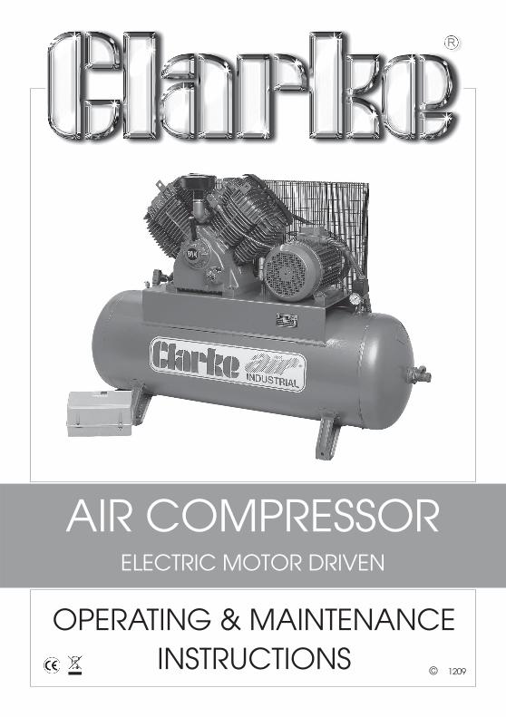
AIR COMPRESSORELECTRIC MOTOR DRIVEN
OPERATING & MAINTENANCEINSTRUCTIONS
1209©

Thank you for purchasing this CLARKE Industrial Air Compressor.
Before putting to use, please read this booklet thoroughly to ensure that installationis correctly carried out and the maintenance schedules correctly followed. This, inturn, will ensure the compressor will provide you with long and trouble free service.
Please note that electrically driven machines are designed for indoor use only.
CONTENTS
Safety Precautions .......................................................................... 3
Noise Levels .................................................................................... 3
Installation ........................................................................................ 4
Suggested Fuse Ratings ................................................................. 4
Electrical Connections ................................................................... 5
Lubrication ...................................................................................... 5
Before Starting Compressor .......................................................... 5
To Start Compressor ....................................................................... 6
To Stop Compressor ....................................................................... 6
General Arrangement - Stationary ............................................... 7
Outlet Pressure Adjustments .......................................................... 8
Trouble Shooting ............................................................................. 9-13
Spare parts and service ................................................................. 13
Maintenance Chart ....................................................................... 14
Torque Values for Cylinder Head Bolts .......................................... 14
Declaration of Conformity ............................................................. 15
This Clarkeproduct is guaranteed against faulty manufacture for a period of12 months from the date of purchase. Please keep your receipt as proof ofpurchase.
This guarantee is invalid if the product is found to have been abused ortampered with in any way, or not used for the purpose for which it wasintended.
Faulty goods should be returned to their place of purchase, no product canbe returned to us without prior permission.
This guarantee does not effect your statutory rights.
GUARANTEE
2
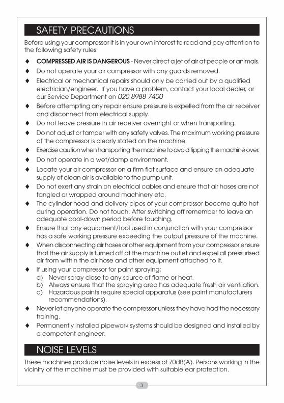
SAFETY PRECAUTIONSBefore using your compressor it is in your own interest to read and pay attention tothe following safety rules:
♦ COMPRESSED AIR IS DANGEROUS - Never direct a jet of air at people or animals.
♦ Do not operate your air compressor with any guards removed.
♦ Electrical or mechanical repairs should only be carried out by a qualifiedelectrician/engineer. If you have a problem, contact your local dealer, orour Service Department on 020 8988 7400
♦ Before attempting any repair ensure pressure is expelled from the air receiverand disconnect from electrical supply.
♦ Do not leave pressure in air receiver overnight or when transporting.
♦ Do not adjust or tamper with any safety valves. The maximum working pressureof the compressor is clearly stated on the machine.
♦ Exercise caution when transporting the machine to avoid tipping the machine over.
♦ Do not operate in a wet/damp environment.
♦ Locate your air compressor on a firm flat surface and ensure an adequatesupply of clean air is available to the pump unit.
♦ Do not exert any strain on electrical cables and ensure that air hoses are nottangled or wrapped around machinery etc.
♦ The cylinder head and delivery pipes of your compressor become quite hotduring operation. Do not touch. After switching off remember to leave anadequate cool-down period before touching.
♦ Ensure that any equipment/tool used in conjunction with your compressorhas a safe working pressure exceeding the output pressure of the machine.
♦ When disconnecting air hoses or other equipment from your compressor ensurethat the air supply is turned off at the machine outlet and expel all pressurisedair from within the air hose and other equipment attached to it.
♦ If using your compressor for paint spraying:a) Never spray close to any source of flame or heat.b) Always ensure that the spraying area has adequate fresh air ventilation.c) Hazardous paints require special apparatus (see paint manufacturers
recommendations).♦ Never let anyone operate the compressor unless they have had the necessary
training.♦ Permanently installed pipework systems should be designed and installed by
a competent engineer.
NOISE LEVELSThese machines produce noise levels in excess of 70dB(A). Persons working in thevicinity of the machine must be provided with suitable ear protection.
3
INSTALLATIONBefore installing your machine, check that its air output is sufficient for the equipmentto be used. The air output from the compressor must be more than the volume ofair required. We recommend the following:
1. Firm and level site, and the use of floor mountings for stationary compressors- anti-vibration pads. (Do not bolt machines directly to the floor).
2. Dust and damp free environment.
3. Adequate ventilation for:-
a) Air intake to compressor pump (in order to draw in clean air).
b) Cooling to compressor pump, and electric motor.
4. To allow sufficient access for servicing, a minimum clearance of 500mm mustbe allowed around the machine.
5. The power cable from the main supply must be large enough to carry thestarting and running load of the electric motor. This is particularly relevant ifthe compressor is some distance from the source of supply.
6. Electrical installations should be completed by a qualified electrician.
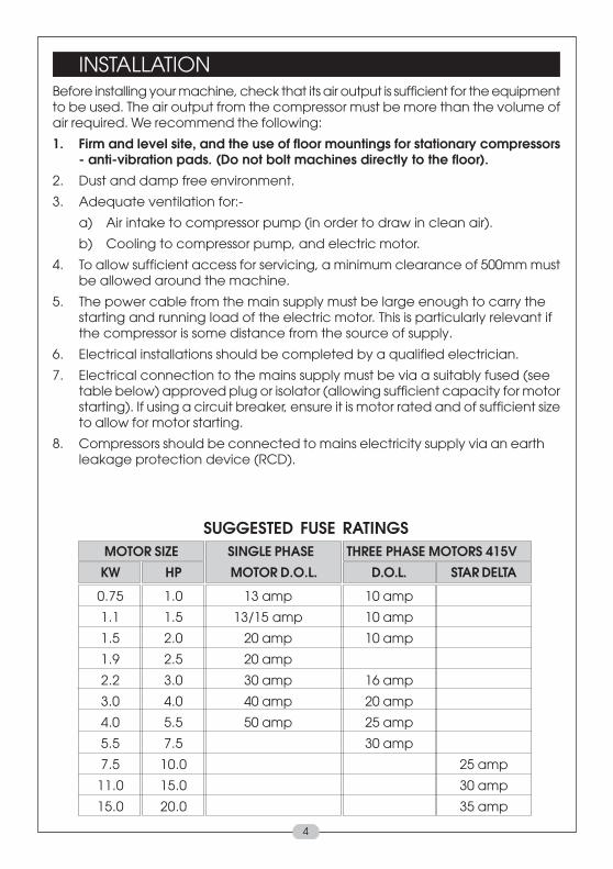
7. Electrical connection to the mains supply must be via a suitably fused (seetable below) approved plug or isolator (allowing sufficient capacity for motorstarting). If using a circuit breaker, ensure it is motor rated and of sufficient sizeto allow for motor starting.
8. Compressors should be connected to mains electricity supply via an earthleakage protection device (RCD).
SUGGESTED FUSE RATINGS MOTOR SIZE SINGLE PHASE THREE PHASE MOTORS 415V
KW HP MOTOR D.O.L. D.O.L. STAR DELTA
0.75 1.0 13 amp 10 amp
1.1 1.5 13/15 amp 10 amp
1.5 2.0 20 amp 10 amp
1.9 2.5 20 amp
2.2 3.0 30 amp 16 amp
3.0 4.0 40 amp 20 amp
4.0 5.5 50 amp 25 amp
5.5 7.5 30 amp
7.5 10.0 25 amp
11.0 15.0 30 amp
15.0 20.0 35 amp
4

ELECTRICAL CONNECTIONS
IMPORTANT - SINGLE PHASE MACHINES ONLY
The wires in the mains lead of this machine are coloured in accordance with thefollowing code:
Green and Yellow – Earth
Blue – Neutral
Brown – Live
As the colours of the wires in the lead of this appliance may not correspond withthe coloured markings identifying the terminals in your plug, proceed as follows.
• The wire which is coloured green and yellow must be connected to theterminal which is marked with the letter E or by the earth Symbol ( ) orcoloured green or green and yellow.
• The wire which is coloured blue must be connected to the terminal which ismarked with the letter N or coloured black.
• The wire which is coloured brown must be connected to the terminal which ismarked with the letter L or coloured red.
WARNING: This machine must be earthed.110V ModelConnect the mains lead to a suitable 110V (50Hz) electrical supply throughanapproved plug or a suitably fused isolator switch. If using a portable 110Vtransformer,make sure it has a rated capacity sufficient to take the load of theair compressor.
If in any doubt, consult a qualified electriction.
5

TO START COMPRESSOR1. Switch on isolator (mains supply)
2. Switch on pressure switch (lift knob or twist switch). (Fig.2, item 22)
3. Check rotation (Flywheel/Fan blows air over pump)
4. Run compressor for 10 minutes with outlet valves open (first time of operation only).
5. Close valves and check that pressure does not exceed maximum workingpressure (stamped on machine plate), if the pressure exceeds the maximumworking pressure stated, stop the machine (see below), vent the system andcontact the Carke Service Department.
TO STOP COMPRESSOR1. Switch off at the pressure switch (Push knob down or turn switch). (Fig.2, item 22)
2. Isolate from the Mains Supply.
2. Drain air receiver (release drain tap).
WARNING:Compressor pumps, delivery pipes will remain hot for some time after use.
NOTE: When starting compressors up to and including the 3HP models, an autobleed valve will operate and air will be heard vent. This is quite normal and shouldnot cause concern. The valve should close after several seconds. Should it fail toclose, consult your Clarke dealer.
6
LUBRICATION:-Pump: Use Clarke compressor oil, as indicated on machine plate.
BEFORE STARTING COMPRESSOR, CHECK:-1. Compressor Pump Oil Level by - (a) Dipstick (to level marked)
or - (b) Sight glass (see fig.1)
2. (a) Automatic Control:- Pressure switch ON/OFF switch is inthe OFF position
Fig.1
WARNING1.Before starting compressor, open all outlet valves.2.The following start and stop instructions must be followed in the correctsequence to avoid serious damage to the compressor/motor.
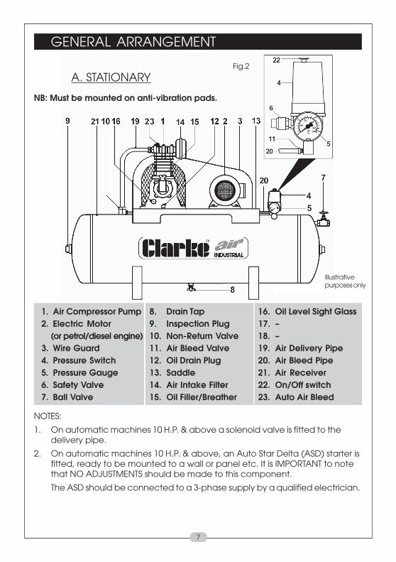
GENERAL ARRANGEMENT
1. Air Compressor Pump 8. Drain Tap 16. Oil Level Sight Glass2. Electric Motor 9. Inspection Plug 17. – (or petrol/diesel engine) 10. Non-Return Valve 18. –3. Wire Guard 11. Air Bleed Valve 19. Air Delivery Pipe4. Pressure Switch 12. Oil Drain Plug 20. Air Bleed Pipe5. Pressure Gauge 13. Saddle 21. Air Receiver6. Safety Valve 14. Air Intake Filter 22. On/Off switch7. Ball Valve 15. Oil Filler/Breather 23. Auto Air Bleed
NOTES:
1. On automatic machines 10 H.P. & above a solenoid valve is fitted to thedelivery pipe.
2. On automatic machines 10 H.P. & above, an Auto Star Delta (ASD) starter isfitted, ready to be mounted to a wall or panel etc. It is IMPORTANT to notethat NO ADJUSTMENTS should be made to this component.
The ASD should be connected to a 3-phase supply by a qualified electrician.
A. STATIONARY
NB: Must be mounted on anti-vibration pads.
Fig.2
7
Illustrativepurposes only

OUTLET PRESSURE ADJUSTMENTS
PORTABLE COMPRESSORS1. Pressure Adjusting Knob
2. Outlet Taps
3. Quick Fit Nuts
4. Pressure Gauge
To adjust outlet pressure:To increase pressure - turn knob (1) clockwise. Todecrease pressure - turn knob (1)anticlockwise.
Outlet taps - slide knurled section (2) awayfrom body to open, push towards body toclose.
NOTE: Pressure Gauge (4). Pressure shown will differ by approximately 1 bardepending on whether the outlets are open/closed.
STATIONARY COMPRESSORSThese machines are not supplied with the facility to adjust outlet pressure. Acomprehensive range of airline accessories is available from your local CLARKEstockist.
OVERLOAD BUTTONThe electric motor is fitted with an automaticoverload detector which will stop the motor ifan overload is detected.
If this happens,
1. Switch off at the pressure switch (Pushknob down or turn switch).
• Allow the compressor to cool down for 5-10 minutes.
2. Press the Reset button shown on the right.
3. Switch on pressure switch (lift knob or twist switch).
If the overload trips repeatedly, it may indicate a fault with the compressor, in thiscase you should contact the Clarke service department (see page 13).
Fig.6
8
OTHER PRODUCTS WITHIN OUR RANGE In addition to Air Compressors from 3–80 cfm, weoffer a vast range of airtools and airline equipment. Please ask your local dealer fordetails of our range or a copy of our Power Products Catalogue
Illustrativepurposes only(may vary)

TROUBLE SHOOTING CHART
SYMPTOM PROBABLE CAUSES REMEDY
Compressor will not Fault in electrical Let an electrician checkstart automatically. installation. electrical installation.
a) current supply failure.
b) voltage drop.
c) motor starter faulty.
d) motor incorrectly connected or faulty.
e) starter overload has Reset by depressing tripped out. button.
f) Pressure switch Have pressure switch defective. changed by an electrician.
g) Fuse blown. Check fuse rating - replace.
Fuses keep blowing. Inadequate size fuse Replace with reference toinstalled. chart on page 4.
Fault in motor. Contact Clarke Service
Compressor unit Non-return valve leaking Disconnect from the mainsstarts, but stops (compressor unit is on load supply and empty airagain after only a during start). receiver. Clean or replace
few revolutons. Non-return valve blocked, non-return valve.possibly frozen up. Thaw non-return valve out
(Unit must be installed infrost-free place).
Solenoid valve leaking or Contact Clarke Servicedefective (only applies to Department10 hp machines and above).
9
IMPORTANT!1. Any remedial work that may be required must be carried out by a qualified
electrician/engineer.
2. Disconnect from the mains supply before removing any parts from thecompressor.
3. Empty Air Receiver of Air before dismantling any part of the compressor unit’spressure system.
4. If your compressor develops a fault do not use until the fault has been rectified.
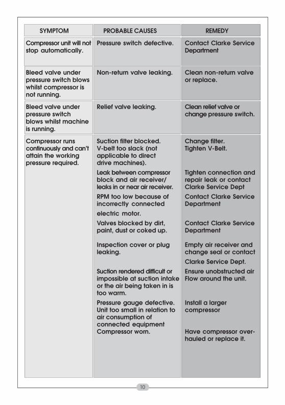
SYMPTOM PROBABLE CAUSES REMEDY
Compressor unit will not Pressure switch defective. Contact Clarke Servicestop automatically. Department
Bleed valve under Non-return valve leaking. Clean non-return valvepressure switch blows or replace.whilst compressor isnot running.
Bleed valve under Relief valve leaking. Clean relief valve orpressure switch change pressure switch.blows whilst machineis running.
Compressor runs Suction filter blocked. Change filter.continuously and can’t V-belt too slack (not Tighten V-Belt.attain the working applicable to directpressure required. drive machines).
Leak between compressor Tighten connection andblock and air receiver/ repair leak or contactleaks in or near air receiver. Clarke Service DeptRPM too low because of Contact Clarke Serviceincorrectly connected Departmentelectric motor.Valves blocked by dirt, Contact Clarke Servicepaint, dust or coked up. Department
Inspection cover or plug Empty air receiver andleaking. change seal or contact
Clarke Service Dept.Suction rendered difficult or Ensure unobstructed airimpossible at suction intake Flow around the unit.or the air being taken in istoo warm.Pressure gauge defective. Install a largerUnit too small in relation to compressorair consumption ofconnected equipmentCompressor worn. Have compressor over-
hauled or replace it.
10

SYMPTOM PROBABLE CAUSES REMEDY
Unusual noise from Bolts loose. Tighten Bolts.
compressor. V-Belt flywheel or cooling Find place of contact andcoil touching belt guard remedy fault.
Flywheel loose. Tighten flywheel.Unit installed on an Move unit to a more solidunsuitable base. base.
Bearings, piston rings or Contact Clarke Servicecylinder worn. DepartmentValve broken. Contact Clarke Service
Department
Bearings of electric motor Contact Clarke Serviceworn. Department.
Compressor becomes Insufficient ventilation See that sufficient air istoo hot. supplied to flywheel or
fan of compressor andthat hot air is properlyvented.
Oil level too low (check Fill with oil - see Page 6.2 or 3 times after stopping).
Wrong direction of Cooling air from flywheelrotation. fan must blow against
compressor.
Fault in valves (machine Contact Clarke Servicenot stopping). Department
Blown head gasket (machine Contact Clarke Servicenot stopping). Department
Dirt on cooling fins or Clean cooling fins andsuction filter. suction filter.
Unit working at too high Contact Clarke Servicea pressure Department.
Non-return valve partly Clean or thaw out non-blocked. return valve.
Compressor being Use a larger compressoroverworked andrunning continuously.
11

SYMPTOM PROBABLE CAUSES REMEDY
12
Compressor unit starts Large amount of Drain off condensationand stops more condensation in air receiver. AT LEAST once a week.frequently than usual. Leaks in control unit or Locate leaks (by means of
inspection cover. soapy water) and repair.Too little pressure differential. Contact Clarke Service
Department
Compressor unit starts Leaks in pipework system Locate and repair leaks.when no air is beingused.
Compressor’s oil Too much oil in compressor. Check oil level 2 or 3consumption rising. minutes after stopping.
Leaks around crank case. Contact Clarke ServiceDepartment
Working temperature of Increase ventilation tocompressor too high because air comprressor.of insufficient cooling.
Unit too small in proportion Connect supplementary.to air consumption.
Semi-automatic unit Load too Convert to fullysmall. automatic operation.
Cylinder worn. Contact Clarke ServiceDepartment
Intake air filter blocked. Clean / Change air filter.
Oil in the air delivered. Sump over full. Reduce oil to correct level.Cylinder worn. Contact Clarke Service
DepartmentIntake air filter blocked. Change air filter.
Condensation in crank Compressor overdimensioned a) Frequent oil changes.case (especially in (operational periods too short b) Reduce cooling of crank2-stage compressors). in relation to resting periods). case (eg. by shielding it
from air stream).c) Contact Clarke Service Department

SYMPTOM PROBABLE CAUSES REMEDY
Condensation at outlet Piping installation incorrect. Consult your local dealer.
points. Compressor taking in air Obtain better fresh-airwhich is too warm. supply for compressor.
Delivery temperature of air a) Use a larger air receiver.from air receiver too high. b) Contact Clarke Service
Department.
Electric Motor too hot: Operational voltage too low. Call an electrician.
maximum temperature Faults in electrical installation Contact Clarke Service90 C (194 F). Department
Cooling fins of electric motor Clean cooling fins.blocked by dirt.
Machine running but Air exhausting from solenoid Check solenoid valve.not pumping air into after starter has changed from Contact Clarke Servicereceiver (10 HP and star to delta. Departmentabove).
13
Spare Parts and Service
For spare parts and service, please contact your nearest dealer, orClarke International, on one of the following numbers.
PARTS & SERVICE TEL.: 020 8988 7400PARTS & SERVICE FAX: 020 8558 3622
or e-mail as follows:PARTS: [email protected]
SERVICE: [email protected]
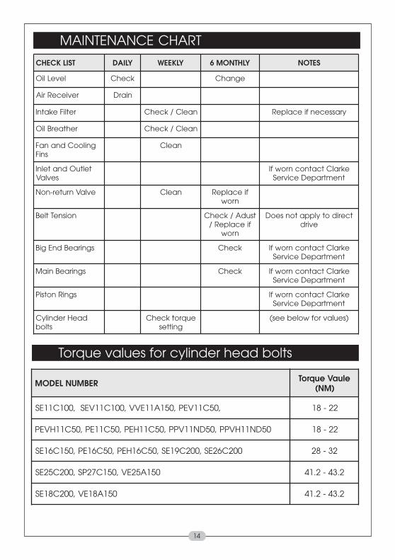
MAINTENANCE CHART
14
REBMUNLEDOM eluaVeuqroT)MN(
,05C11VEP,051A11EVV,001C11VES,001C11ES 22-81
05DN11HVPP,05DN11VPP,05C11HEP,05C11EP,05C11HVEP 22-81
002C62ES,002C91ES,05C61HEP,05C61EP,051C61ES 23-82
051A52EV,051C72PS,002C52ES 2.34-2.14
051A81EV,002C81ES 2.34-2.14
Torque values for cylinder head bolts
TSILKCEHC YLIAD YLKEEW YLHTNOM6 SETON
leveLliO kcehC egnahC
revieceRriA niarD
retliFekatnI naelC/kcehC yrassecenfiecalpeR
rehtaerBliO naelC/kcehC
gnilooCdnanaFsniF
naelC
teltuOdnatelnIsevlaV
ekralCtcatnocnrowfItnemtrapeDecivreS
evlaVnruter-noN naelC fiecalpeRnrow
noisneTtleB tsudA/kcehCfiecalpeR/
nrow
tceridotylppatonseoDevird
sgniraeBdnEgiB kcehC ekralCtcatnocnrowfItnemtrapeDecivreS
sgniraeBniaM kcehC ekralCtcatnocnrowfItnemtrapeDecivreS
sgniRnotsiP ekralCtcatnocnrowfItnemtrapeDecivreS
daeHrednilyCstlob
euqrotkcehCgnittes
)seulavrofwolebees(

15