Electric Mini Tank – Water Heaters CMT-ST70 CMT-1.3 CMT-2 ... · Electric Mini Tank – Water...
20
Electric Mini Tank – Water Heaters CMT-1.3 CMT-2.5 CMT-4.0 Installation and Operating Instruction Manual CMT-ST70 Tempering valve Optionally available
Transcript of Electric Mini Tank – Water Heaters CMT-ST70 CMT-1.3 CMT-2 ... · Electric Mini Tank – Water...
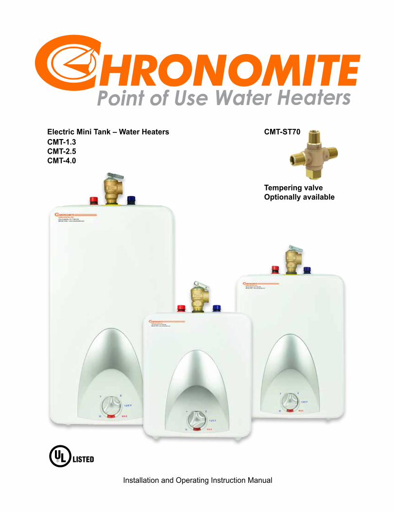
Electric Mini Tank – Water HeatersCMT-1.3CMT-2.5CMT-4.0
Installation and Operating Instruction Manual
CMT-ST70
Tempering valveOptionally available
Page 2 Chronomite Laboratories, Inc. • www.chronomite.com
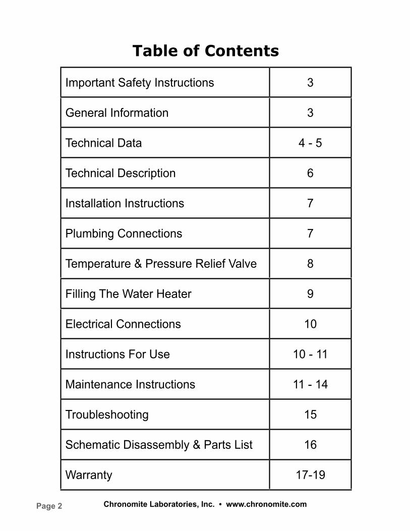
Table of Contents
Important Safety Instructions 3
General Information 3
Technical Data 4 - 5
Technical Description 6
Installation Instructions 7
Plumbing Connections 7
Temperature & Pressure Relief Valve 8
Filling The Water Heater 9
Electrical Connections 10
Instructions For Use 10 - 11
Maintenance Instructions 11 - 14
Troubleshooting 15
Schematic Disassembly & Parts List 16
Warranty 17-19
Page 3Chronomite Laboratories, Inc. • www.chronomite.com
Important safety instructions
Warning : When using electrical appliances, safety precautions to reduce the risk of fire, electric shock or injury to persons should be followed, including:
1. Read all these instructions before using this water heater. 2. This water heater must be grounded. Connect only to properly grounded outlet. See “Grounding instructions” found on page 10.
3. Install or locate this water heater only in accordance with the provided installation instructions.
4. Use this water heater only for its intended use as described in this manual.
5. Do not use an extension cord set with this water heater. If no receptacle is available adjacent to the water heater, contact a qualified electrician to have one properly installed.
6. As with any appliance, close supervision is necessary when used by children.
7. Do not operate this water heater if it has a damaged cord or plug, if it is not working properly, or if it has been damaged or dropped.
8. This water heater should be serviced only by qualified service personnel. Contact nearest authorized service facility for examination, repair, or adjustment. 9. If the unit is installed in an area where there is a potential for freezing, the instructions on page 11 must be followed.
Save these instructionsThe manufacturer and/or distributor is not responsible for damages caused by improper installation, or by
non observance of the instructions in this manual. A qualified, licensed technician must always install the
water heater and conduct all subsequent service work and or maintenance.
Important!!
Never turn the water heater power on until the tank is completely full and water is flowing out of the hot
water faucet.
General Information
The Chronomite Mini Tank water heaters can be used in most under the counter, point of use applications.
Models CMT-1.3, CMT-2.5, and CMT-4.0 are designed to supply hot water for hand washing in a
residential, commercial or industrial environment. The Chronomite Mini tank water heaters are lightweight
and compact and manufactured for easy installation. The CMT-1.3, CMT-2.5, and CMT-4.0 are designed
to be mounted on the wall, or sit on floor.
Page 4 Chronomite Laboratories, Inc. • www.chronomite.com
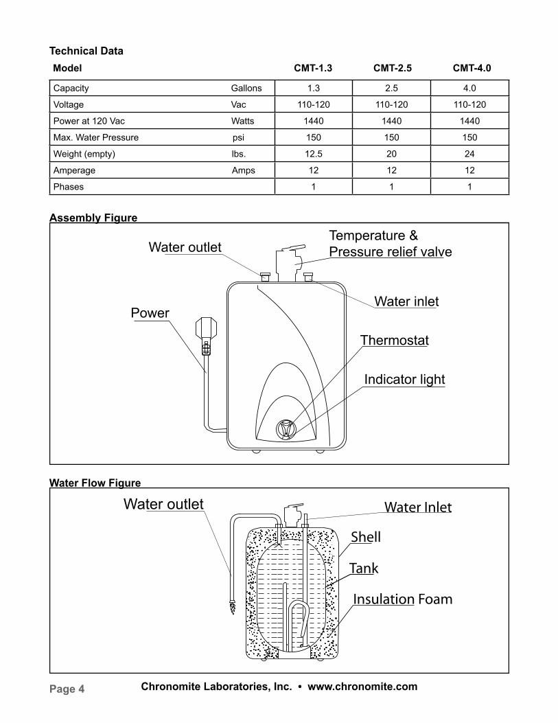
Indicator light
Power
Water outletTemperature & Pressure relief valve
Water inlet
Thermostat
Water outlet
Shell
Tank
Insulation Foam
Water Inlet
Water Flow Figure
Technical DataModel CMT-1.3 CMT-2.5 CMT-4.0
Capacity Gallons 1.3 2.5 4.0
Voltage Vac 110-120 110-120 110-120
Power at 120 Vac Watts 1440 1440 1440
Max. Water Pressure psi 150 150 150
Weight (empty) lbs. 12.5 20 24
Amperage Amps 12 12 12
Phases 1 1 1
Assembly Figure
Page 5Chronomite Laboratories, Inc. • www.chronomite.com
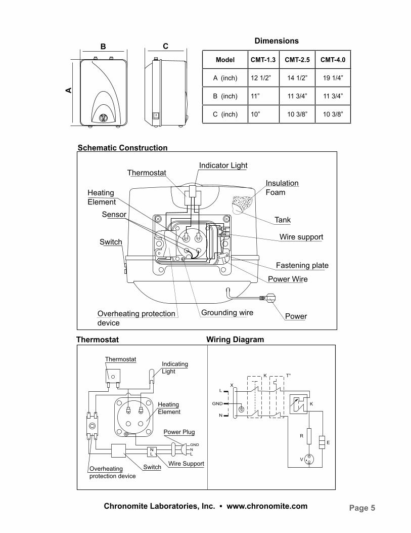
Indicator Light
Fastening plate
Wire support
Grounding wire Power
Power Wire
Tank
Insulation Foam
Thermostat
Heating Element
Sensor
Switch
Overheating protection device
GNDNLL
N
Indicating Light
HeatingElement
Power Plug
Overheating protection device
Switch Wire Support
Thermostat
L
GND
N
X
K
K
T°
RE
V
Thermostat
Schematic Construction
Wiring Diagram
Dimensions
A
B CModel CMT-1.3 CMT-2.5 CMT-4.0
A (inch) 12 1/2” 14 1/2” 19 1/4”
B (inch) 11” 11 3/4” 11 3/4”
C (inch) 10” 10 3/8” 10 3/8”
Page 6 Chronomite Laboratories, Inc. • www.chronomite.com
The CMT-1.3, CMT-2.5, and CMT-4.0 are designed to operate at 150 psi maximum water pressure. Install
a pressure reducing valve if your water pressure is greater than 120 psi.
Caution! The manufacturer cannot be responsible for the damage caused by improper installation or by
failure to follow instructions in this manual. Comply with the Installation Instructions before connecting to
electrical outlet.
Caution! The adjustable thermostat knob has not been pre-set at the factory. Refer to page 11
for instructions.
Caution! Hydrogen gas can be produced in a hot water system served by this heater that has not been
used for a long period of time (generally 2 weeks or more). Hydrogen gas is extremely flammable. To
reduce the risk of injury under these conditions, it is recommended that the hot water faucet be opened for
several minutes at the nearest and most distant sink being served by this water heater before using any
electrical appliance connected to the hot water system i.e. Dishwasher. If hydrogen gas is present, there
will probably be an unusual sound such as air escaping through the faucet as the water begins to flow.
There should be no smoking or open flame near the faucet at this time.
Warning: Installer should review the contents of this manual with the owner upon completion of the
installation, and the manual should remain with the owner and placed in a location close to the
water heater.
Technical Description
There are three Chronomite Mini tank models, a 1.3, 2.5, and 4.0 gallon. The pressure vessel
(water tank) is welded, glass lined steel and is equipped with an anode rod. The water heater is equipped
with a thermostat and a high limit temperature switch. A temperature pressure relief valve is supplied with
the unit.
Page 7Chronomite Laboratories, Inc. • www.chronomite.com
Installation Instructions CMT-1.3/CMT-2.5/CMT-4.0
The installation must be completed by a licensed professional. All state and local codes must be adhered
to. The manufacturer will not be liable for any damages because of failure to comply with these installation
instructions or because of improper installation performed by an unqualified installer.
Choose a location that allows ease of access for maintenance or servicing, ideally installed at least
8” to 9” from the ceiling (inside top of cabinet) or any adjacent walls.
Wall Mounting
Fasten the supplied mounting bracket to the wall. Use screws that are suitable for the wall material and the
weight of the water heater filled to capacity (CMT-1.3 = 24 lbs CMT-2.5 = 41 lbs, CMT-4.0 = 57 lbs). Hang
the water heater on the bracket and pull downwards on the water heater to insure that both “fingers” of the
bracket are seated in the mounting slots. Confirm your water piping orientation (hot and cold) before wall
mounting. Only install in vertical position.
Heater can sit on the floor. Confirm water piping orientation before finalizing on floor. Again, only install in
vertical position! CMT models can also be installed under the sink.
Plumbing Connections
Connect the cold water inlet pipe to the inlet nipple (marked with a blue ring) and the hot water outlet pipe
to the outlet nipple (marked with a red ring).
Important: If Water pipes are copper or bronze, use dielectric connections to prevent corrosion. Failure
to provide dielectric insulation may result in premature tank or nipple failure and may void your warranty.
Insure that the water heater is installed in a level position. Install a shut off valve on the cold water side of
the water heater. The valve is for servicing and the valve should be in the open position when the water
heater is in operation. In order to protect the water heater from heat damage due to soldering, solder
a piece of tubing to a threaded union fitting before screwing the union to the tank. Do not apply heat
directly to inlet or outlet connections.
Page 8 Chronomite Laboratories, Inc. • www.chronomite.com
Temperatures and Pressure Relief Valve
Caution! Install the Temperature/Pressure Relief Valve supplied with the water heater!
Install a discharge pipe from the temperature/pressure relief valve terminating at a sink or drain. Do not
cap or plug the end of the discharge pipe. The discharge pipe must be unobstructed and full sized.
The T/P valve is certified by a nationally recognized test lab that maintains periodic inspections of the
listed equipment and meets the requirements for relief valves and automatic shut off devices for hot
water supply systems ANSI 121.22-1979. The T/P valve is marked with a maximum pressure, which does
not exceed the maximum working pressure of the water heater (150 PSI). Install the T/P valve into the
threaded opening at the top of the water heater using heavy duty Teflon tape. Do not over tighten! Orient
the discharge tubing so that any discharge from the valve will exit within 6 inches above, or at any distance
below the structural floor, and cannot contact any live electrical part.
T/P Valve Discharge Pipe
1. Must not be smaller in diameter than the outlet diameter of the valve, or have any reducing
couplings.
2. Must not be plugged or blocked.
3. Must be made of suitable material for hot water.
4. Must not be over 15’ in length.
5. Must not have more than two elbows.
6. Must terminate at an adequate drain.
7. Must not have a shut off valve between relief valve and tank or relief valve and termination
of discharge.
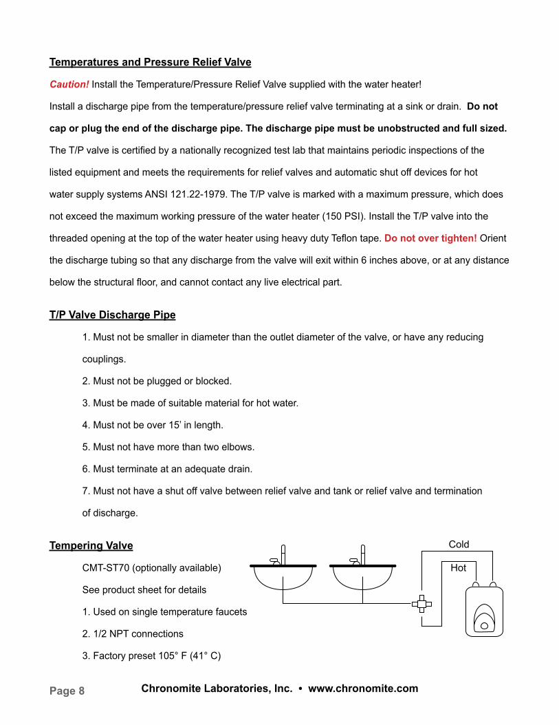
Tempering Valve
CMT-ST70 (optionally available)
See product sheet for details
1. Used on single temperature faucets
2. 1/2 NPT connections
3. Factory preset 105° F (41° C)
Hot
Cold
Page 9Chronomite Laboratories, Inc. • www.chronomite.com
Closed System Thermal Expansion:
Periodic discharge of the T/P relief valve or failure of the element gasket may be due to thermal expansion
in a closed water supply system. The water utility supply meter may contain a check valve, back flow
preventer or water pressure reducing valve which will create a closed water system. During the heating
cycle of the water heater, the heated water expands causing pressure inside the water heater to increase.
The T/P relief valve may discharge hot water under these conditions which results in a loss of energy and
a build up of lime on the relief valve seat.
To prevent this from happening, there are two recommendations:
1. Install a diaphragm-type domestic hot water expansion tank (suitable for potable water) on the
cold water supply line. The expansion tank must have a minimum capacity of 1.5 U.S. gallons for
every 50 gallons of stored water.
2. Install a 125 PSI pressure relief valve in the cold water supply line. Make sure the discharge
of this valve is directed to an open drain and protected from freezing. Contact your local
water utility or plumbing inspector for information on how to control this situation. Never plug the
outlet of the relief valve.
Filling the Water Heater
Caution! Before plugging the water heater electric cord into an outlet, be sure that the system is
completely charged with water and All AIR IS REMOVED. Before connecting the power, fill the tank
and system with water and check for leaks. To be sure that all air is out of the water system, open the hot
water faucets on your fixtures until constant water flows from them. Otherwise any air remaining in the tank
will cause the water heater element to self destruct.
Procedure:
1. Open the hot water faucet.
2. Open the cold water supply valve.
3. When continuous water flows out of the faucet, the tank is filled.
4. Close the hot water faucet.
5. Check entire system for leaks.
Page 10 Chronomite Laboratories, Inc. • www.chronomite.com
Electrical Connections
To be certain that all of the air is out of the water heater, open the hot water faucet on your fixtures until
constant water flows from them. If air remains in the tank, the element will be damaged when the electric
cord is plugged in.
Connect the Water Heater to a Grounded Outlet.
The water heater is fitted with a power cord that is intended to plug into a grounded 110-120 VAC
receptacle. Adhere to all pertinent State and local codes. Install the correct size circuit breaker into
the master panel. The Chronomite water heater was manufactured and wired in accordance with UL
requirements.
The water heater is equipped with an overheat limiting device with a manual reset. Also known as the
temperature high limit, this device has been factory installed to interrupt the power supply in the event of a
thermostat failure. This water heater is designed for only 110-120V electrical service!
Do not connect to higher or lower voltage.
Failure to use proper voltage may result in personal injury and/or property damage. If the supplied
electrical power cord is either damaged or not long enough, do not use an extension cord. Have a
licensed electrician replace the power cord.
Instructions for Use
Congratulations! You are now ready to use your water heater. Run the hot water at a nearby
sink and evaluate the hot water temperature. Make any temperature adjustment using instructions
on page 11.
Page 11Chronomite Laboratories, Inc. • www.chronomite.com
Setting the Thermostat
The water heater is equipped with an adjustable thermostat that once set will automatically control water
temperature. The red indicator lamp remains illuminated while the water is being heated. If the water in
the tank is at the desired temperature the lamp will NOT be illuminated. The temperature adjusting knob
will increase the temperature by turning the knob clockwise and decrease the water temperature by turning
the knob counter clockwise. When not being used for a lengthy period of time, you can conserve energy by
reducing the water temperature setting.
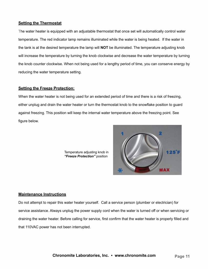
Setting the Freeze Protection:
When the water heater is not being used for an extended period of time and there is a risk of freezing,
either unplug and drain the water heater or turn the thermostat knob to the snowflake position to guard
against freezing. This position will keep the internal water temperature above the freezing point. See
figure below.
Maintenance Instructions
Do not attempt to repair this water heater yourself. Call a service person (plumber or electrician) for
service assistance. Always unplug the power supply cord when the water is turned off or when servicing or
draining the water heater. Before calling for service, first confirm that the water heater is properly filled and
that 110VAC power has not been interrupted.
Temperature adjusting knob in “Freeze Protection” position
Page 12 Chronomite Laboratories, Inc. • www.chronomite.com
Maintenance Instructions (cont.)
Warning : Before servicing or cleaning the water heater, turn off the power switch and disconnect the
power cord from the electrical outlet.
Note : For most maintenance operations, the water heater will be drained. In all cases before draining
first turn off the power switch and then unplug power cord.
Draining and removing the water heater:
1. Unplug the water heater.
2. Open a hot water faucet to let hot water run out. Allow water to flow until water is no longer hot.
3. Turn off the cold water supply to the water heater.
4. Close the hot water faucet.
5. Disconnect the water heater from both the hot and cold water connections.
6. If possible siphon out remaining water.
7. Carefully detach the water heater from the wall.
8. Tilt the water heater to drain remaining water out of the heater.
Removing the heating element:
1. Turn off power supply, unplug water heater power cord and drain (see above).
2. Remove cover.
3. Remove all the line wires from the heating element.
4. Unscrew the heating element retaining nuts.
5. Remove the element.
Descaling the heating element :
Scale deposits can affect the heating capability of the element. Heavy scale can even cause the element
to burn out. The element can be descaled chemically or manually.
1. Remove the heating element (see instructions above).
2. To descale chemically, soak the heating element in white vinegar or other descaling solution and
then rinse well with fresh water.
Page 13Chronomite Laboratories, Inc. • www.chronomite.com
Descaling the Heating Element (cont.)
3. To descale manually, let element dry and then using a non metallic brush similar to a tooth
brush; brush the residue from the element. Avoid damaging the surface of the element.
4. Reinstall the element and gasket.
5. Refill tank with water before turning on the power to the water heater.
Replacing the Heating Element
1. Unplug and drain the water heater (see prior instructions).
2. Remove heating element noting original positions of all connections.
3. Install new element with gasket making sure the new element and gasket are
positioned correctly.
4. Tighten retaining nuts and make the wire connections to their original locations.
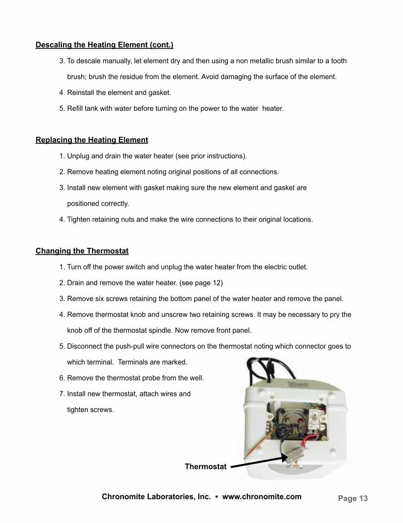
Changing the Thermostat
1. Turn off the power switch and unplug the water heater from the electric outlet.
2. Drain and remove the water heater. (see page 12)
3. Remove six screws retaining the bottom panel of the water heater and remove the panel.
4. Remove thermostat knob and unscrew two retaining screws. It may be necessary to pry the
knob off of the thermostat spindle. Now remove front panel.
5. Disconnect the push-pull wire connectors on the thermostat noting which connector goes to
which terminal. Terminals are marked.
6. Remove the thermostat probe from the well.
7. Install new thermostat, attach wires and
tighten screws.
Thermostat
Page 14 Chronomite Laboratories, Inc. • www.chronomite.com
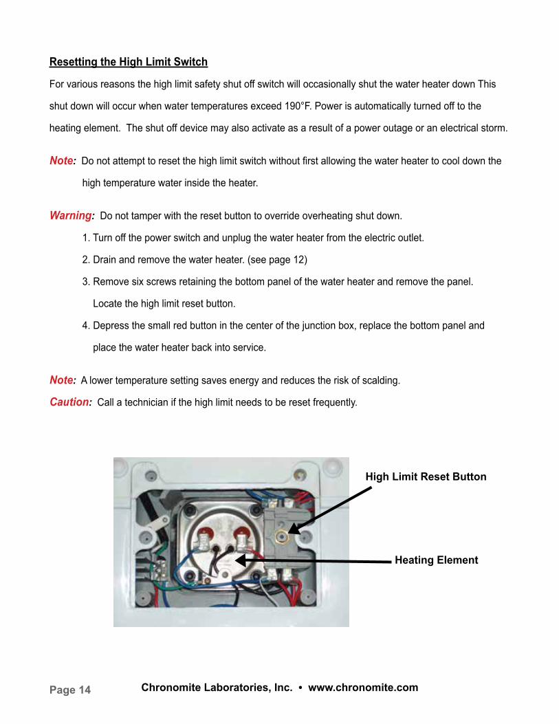
High Limit Reset Button
Heating Element
Resetting the High Limit Switch
For various reasons the high limit safety shut off switch will occasionally shut the water heater down This
shut down will occur when water temperatures exceed 190°F. Power is automatically turned off to the
heating element. The shut off device may also activate as a result of a power outage or an electrical storm.
Note: Do not attempt to reset the high limit switch without first allowing the water heater to cool down the
high temperature water inside the heater.
Warning: Do not tamper with the reset button to override overheating shut down.
1. Turn off the power switch and unplug the water heater from the electric outlet.
2. Drain and remove the water heater. (see page 12)
3. Remove six screws retaining the bottom panel of the water heater and remove the panel.
Locate the high limit reset button.
4. Depress the small red button in the center of the junction box, replace the bottom panel and
place the water heater back into service.
Note: A lower temperature setting saves energy and reduces the risk of scalding.
Caution: Call a technician if the high limit needs to be reset frequently.
Page 15Chronomite Laboratories, Inc. • www.chronomite.com
TroubleshootingProblem: Water does not get hot
1. Make sure the power supply is on and working.
2. If light does not come on, check that the reset button is pushed in; follow steps from previous
section.
3. If the indicator light is illuminated, but water temperature does not get hot at the sink, test for a
plumbing crossover as follows; shut off cold water supply to water heater and open hot
water tap. There should be no water flowing. Any continuous flow indicates a cross over which will
effect the temperature and will need to be corrected.
4. If there is no crossover, then replace the heating element (see previous sections).
Problem: Indicator light not on
1. If the light does not come on, but water gets hot, check for faulty indicator light.
2. Check reset button; follow steps from previous section.
Problem: Brown water
1. Brown or rusty water indicates a “spent” anode rod. Replace anode rod.
Problem: Odor in water
1. Smelly water could be due to an unusual reaction between local water and the heater’s anode
rod. Check anode rod.
Problem: Water is too hot
1. Turn the temperature knob counter clockwise to a lower temperature setting. If temperature does
not lower within 60 minutes, then replace thermostat.
Problem: Water is not hot enough
1. Under Instructions for Use, see “Setting the thermostat”.
Problem: Water is leaking
1. Turn off power switch and unplug water heater from 110 VAC outlet.
2. Check water fittings and T&P fitting in the top of the tank.
3. Remove cover and inspect heating element gasket.
Page 16 Chronomite Laboratories, Inc. • www.chronomite.com
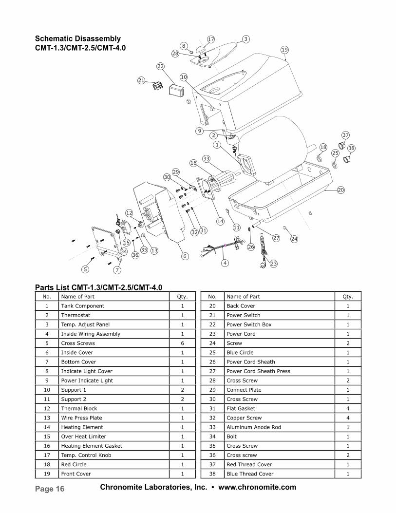
No. Name of Part Qty.
1 Tank Component 1
2 Thermostat 1
3 Temp. Adjust Panel 1
4 Inside Wiring Assembly 1
5 Cross Screws 6
6 Inside Cover 1
7 Bottom Cover 1
8 Indicate Light Cover 1
9 Power Indicate Light 1
10 Support 1 2
11 Support 2 2
12 Thermal Block 1
13 Wire Press Plate 1
14 Heating Element 1
15 Over Heat Limiter 1
16 Heating Element Gasket 1
17 Temp. Control Knob 1
18 Red Circle 1
19 Front Cover 1
Schematic DisassemblyCMT-1.3/CMT-2.5/CMT-4.0
Parts List CMT-1.3/CMT-2.5/CMT-4.0
22
92
1
75
1633
2930
12
13
15
34 3536
236
27
14
18
1132 31
25
37
38
26
20
24
10
8
28
3
21
17
19
4
No. Name of Part Qty.
20 Back Cover 1
21 Power Switch 1
22 Power Switch Box 1
23 Power Cord 1
24 Screw 2
25 Blue Circle 1
26 Power Cord Sheath 1
27 Power Cord Sheath Press 1
28 Cross Screw 2
29 Connect Plate 1
30 Cross Screw 1
31 Flat Gasket 4
32 Copper Screw 4
33 Aluminum Anode Rod 1
34 Bolt 1
35 Cross Screw 1
36 Cross screw 2
37 Red Thread Cover 1
38 Blue Thread Cover 1
Page 17Chronomite Laboratories, Inc. • www.chronomite.com
Chronomite Mini Tank Water Heaters – Limited One (1) Year Warranty Coverage
Chronomite warranties this water heater to the Owner (hereinafter “Owner”) of the water heater at the
original installation location against defects in material and workmanship for the periods specified below.
Warranty Period
1. When a failure of the inner tank of a Chronomite Mini Tank water heater, exposed to normal
usage (not including recirculating applications), occurs within one (1) year from the date of the
original installation and is supplied with potable water, deemed not to be hard water, and such
failure is proven to be a result of a defect in material or workmanship or within one (1) year if used
as part of a recirculating application or with hard water, Chronomite will furnish to such owner a
new water heater of the then prevailing comparable model.
2. If any component part (other than the inner tank) is proven to be defective in material or
workmanship within one (1) year from date of original installation used with potable water deemed
not to be hard water or within one (1) year if used as part of a recirculating system, or with hard
water, or if used in other than a single family residential dwelling, Chronomite will furnish the Owner
with a replacement of the defective part(s).
3. Verification of Date of Original Installation- When Owner can not verify or document the original
date of installation, the warranty period begins on the date of manufacture marked on the tag
affixed to the water heater.
Exclusions
1. This limited warranty shall be the exclusive warranty made by the manufacturer and is made in
lieu of all other warranties, expressed or implied (whether written or oral), including, but not limited
to, warranties or merchantability and fitness for a particular purpose.
2. The Manufacturer shall not be liable for any incidental, consequential, special or contingent
damages or expenses arising, directly or indirectly, from any defect in the water heater or the use
of the water heater.
Page 18 Chronomite Laboratories, Inc. • www.chronomite.com
Exclusions Cont.
3. The Manufacturer shall not be liable for any water damage arising, directly or indirectly, from any
defect in the water heater component part(s) or from its use.
4. Manufacturer shall not be liable under this warranty if:
a) The water heater or any of its component parts has been subject to excessive water
pressure, misuse, abuse, alteration, neglect or accident.
b) The water heater has not been installed in accordance with the applicable local plumbing,
electrical and/or building code(s) and/or regulation(s).
c) The water heater has not been installed in accordance with the printed manufacturer’s
instructions.
d) The water heater is not continuously supplied with potable water, otherwise described as
dry firing.
e) The water heater is exposed to conditions resulting from floods, earthquakes, winds, fire,
lightning or circumstances beyond the control of the manufacturer
f) The water heater is installed by non-qualified personnel.
5. The owner and not the Manufacturer or his agent/representative shall be liable for and shall
pay for all field charges for labor or other expenses incurred in the removal and/or repair of the
water heater or any expense incurred by the Owner in order to repair the water heater.
Some states do not allow the exclusion or limitation of incidental or consequential damages, so the above
limitation or exclusion may not apply to you. This warranty gives you specific legal rights and you may also
have other rights which may vary from state to state.
Important: Owner should retain this document.
Note: Your Chronomite quality water heater should be installed in such a manner that if it should leak, the
resulting flow of water will not cause damage to the area in which it is installed.
Page 19Chronomite Laboratories, Inc. • www.chronomite.com
How the owner can secure service assistance or make a warranty claim
1. Owner should contact the dealer who sold the water heater covered by this warranty.
2. Owner should submit the warranty claim directly to Chronomite at the address listed below, and
they will arrange for the handling of the claim.
3. Whenever a warranty service request is made, be sure to include Proof of Purchase, the water
heater model number and the date of manufacture, date of installation, Dealer’s name and
the watts and voltage.
4. When returning the water heater or component part(s), they must be individually tagged and
identified with the Returned Goods Authorization # issued by Chronomite and shipped prepaid
to Chronomite at the address below.
Chronomite Laboratories, Inc.17451 Hurley St. City of Industry, CA 91744
T: 800.447.4962 • P: 626.937.4270
www.chronomite.com L1T00004
2/2014


![cMT-G01 Startup Guide - · PDF file[cMT Series] » [Maintenance] » [cMT-G01 OS Upgrade]. ... cMT Gateway Viewer can read from or write to PLC. ... cMT-G01 Startup Guide](https://static.fdocuments.in/doc/165x107/5ab85bac7f8b9ad13d8c70d9/cmt-g01-startup-guide-cmt-series-maintenance-cmt-g01-os-upgrade-cmt.jpg)