
Electric Machinery Fundamentals, 4th Edition -...
48
CHAPTER 10 SINGLE-PHASE AND SPECIAL-PURPOSE MOTORS C hapte rs 4 through 7 were devoted to the operation orthe two major classes of ac machines (synchronous and inducti on) on three-phase power systems. Motors and generators of these types are by far the most common ones in larger commercial and industrial settings. However, most homes and small businesses do not have three-phase power available. For such locati ons, all motors must run from s ingle-phase power sources. nli s chapter dea ls with the theory and operation of two major types of s in gle-phase motors: the universal motor and the s in gle- phase induction moto r. The uni versal motor, which is a straightforward extension of the se ri es de motor, is desc ri bed in Section 10.1. The sin gle-phase induc ti on motor is described in Sections 10. 2 to 10.5. The major problem associated with the design of s ingle-phase inducti on motors is that, unlike three-phase power sources, a sin gle-phase source does not produce a rotat- ing magne ti c fi e ld. Inst ead, the magne ti c fi e ld produced by a sin gle-phase source remains stationary in position and pulses with time. Since there is no net rotating magnetic field, conve nti onal induction motors ca nnot func ti on, and special de- signs are n ecessa ry. In addition, there are a number of spec ial-purpose motors which have not been previous ly covered. These include reluctance motors, hysteresis motors, stepper motor s, and brushless dc mot ors . 1lley are included in Section 10.6. 633
Transcript of Electric Machinery Fundamentals, 4th Edition -...
CHAPTER
10 SINGLE-PHASE AND
SPECIAL-PURPOSE MOTORS
Chapters 4 through 7 were devoted to the operation orthe two major classes of ac machines (synchronous and induction) on three-phase power systems.
Motors and generators of these types are by far the most common ones in larger commercial and indu strial settings. However, most homes and small businesses do not have three-phase power available. For such locations, all motors must run from single-phase power sources. nlis chapter deals with the theory and operation of two major types of single-phase motors: the uni versal motor and the singlephase induction motor. The uni versal motor, which is a straightforward extension of the series de motor, is descri bed in Section 10.1.
The single-phase inducti on motor is described in Sections 10.2 to 10.5. The major problem associated with the design of single-phase induction motors is that, unlike three-phase power sources, a sing le-phase source does not produce a rotating magnetic fi e ld. Instead, the magneti c fie ld produced by a single-phase source remains stationary in position and pulses with time. Since there is no net rotating magnetic field , conve ntional induction motors cannot functi on, and special designs are necessary.
In addition, there are a number of special-purpose motors which have not been previously covered. These include reluctance motors, hysteresis motors, stepper motors, and brushless dc motors. 1lley are included in Section 10.6.
633

634 ELECTRIC MACHINERY RJNDAMENTALS
v,
""CURE 10-1 Equivalent cin;uit of a univeTS3.1 motor.
10.1 THE UNIVERSAL MOTOR
Perhaps the simplest approach to the design of a motor that will operate on a single-phase ac power source is to take a dc machine and run it from an ac supply. Recall from Chapter 8 that the induced torque of a dc motor is given by
(8-49)
If the polarity of the voltage applied to a shunt or series dc motor is reversed, both the direction of the fie ld flux and the direction of the armature current reverse, and the resulting induced torque continues in the same direction as before. Therefore , it should be possible to achieve a pulsating but unidirectional torque from a dc motor connected to an ac power supply.
Such a design is practical only for the series dc motor (see Figure 10- 1), since the annature current and the field current in the machine must reverse at exactly the same time. For shunt dc motors, the very high fie ld inductance tends to delay the reversal of the fie ld current and thus to unacceptably reduce the average induced torque of the motor.
In order for a series dc motor to function effectively on ac, its field poles and stator frame must be complete ly lami nated. If they were not complete ly laminated, their core losses would be enonnous. When the poles and stator are laminated, this motor is often called a universal motor, since it can run from either an ac or a dc source.
When the motor is running from an ac source, the commutation will be much poorer than it would be with a dc source. The extra sparking at the brushes is caused by transfonner action inducing voltages in the coil s undergoing commutati on. These sparks significantly shorten brush life and can be a source of radio-frequency interference in certain environments.
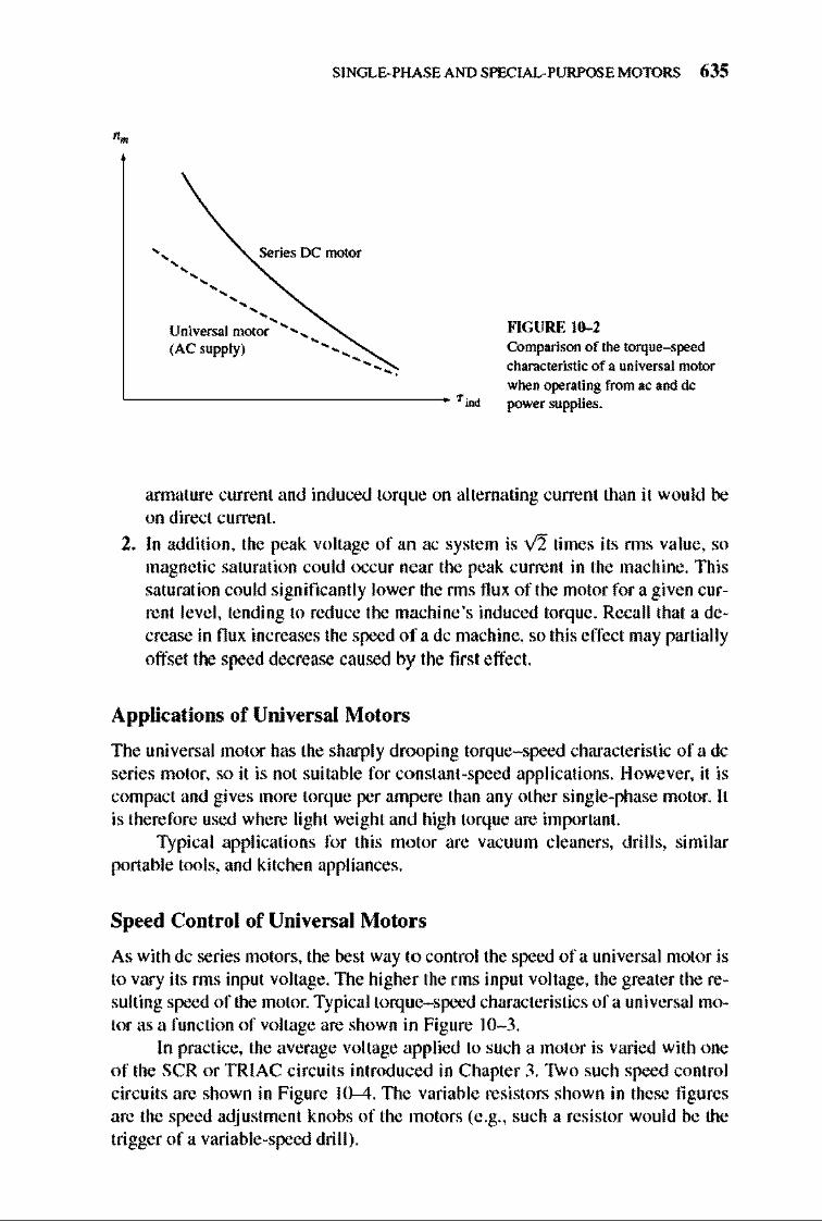
A typical torque-speed characteristic of a universal motor is shown in Figure 10- 2. It differs from the torque-speed characteristic of the same machine operating from a dc voltage source for two reasons:
I. The armature and field windings have quite a large reactance at 50 or 60 Hz. A significant part of the input voltage is dropped across these reactances, and therefore Ell is smaller for a given input voltage during ac operation than it is during dc operation. Since Ell = Kcpw, the motor is slower for a given
SINGLE-PHASE AND SPECIAL-PURPOSE MOTORS 635
" Series IX motor
""""""
Universal motor .........
(AC supply) ........................ ...
""GURE 10-2 Comparison of the torque-speed characteristic of a universal motor
when operating from ac and dc L ________________ Tind power supplies.
annature current and induced torque on alternating current than it wou ld be on direct current.
2. In addition, the peak voltage of an ac system is V2 times its nns value, so magnetic saturation could occur near the peak current in the machine. This saturation could significantly lower the nns nux of the motor for a given current level, tending to reduce the machine 's induced torque. Recall that a decrease in flux increases the speed of a dc machine, so this effect may partially offset the speed decrease caused by the first effect.
Applications of Universal Motors
The universal motor has the sharply drooping torque- speed characteristic of a dc series motor, so it is not suitable for constant-speed applications. However, it is compact and gives more torq ue per ampere than any other single-phase motor. It is therefore used where light weight and high torq ue are important.
Typical applications for this motor are vacu um cleaners, dri ll s, similar portable tools, and kitchen appliances.
Speed Control of Universal Motors
As with dc series motors, the best way to control the speed of a universal motor is to vary its nns input voltage. The higher the rms input voltage, the greater the resulting speed of the motor. Typical torq ue-speed characteristics of a universal motor as a function of voltage are shown in Figure 10- 3.
In practice, the average voltage applied to such a motor is varied with one of the SCR or TRIAC circuit s introduced in Chapter 3. Two such speed control circuits are shown in Figure 10-4. TIle variable resistors shown in these fi gures are the speed adjustment knobs of the motors (e.g., such a resistor would be the trigger of a variable-speed dri II ).

636 ELECTRIC MACHINERY RJNDA MENTALS
v,
v,
v,
'--------''--------------',,------___ Tjoo
""GURE 10-3 The effect of changing teffilinal voltage on the torque-speed characteristic of a universal motor.
+
/. ~c 0,
,n D,
= = C ~DIAC
(a)
L, (series field)
C;) - s CR
D2 is a freewheeling diode to control inductive k:ick: effects.
+~----~------------,
Rc
+ v (t)
TRIAC C
,b, ""GURE 10-4 Sample universal motor speed-control ci["(;uits. (a) Half-wave; (b) full-wave.
o o
o
SINGLE-PHASE AND SPECIAL-PURPOSE MOTORS 637
Stator
o o
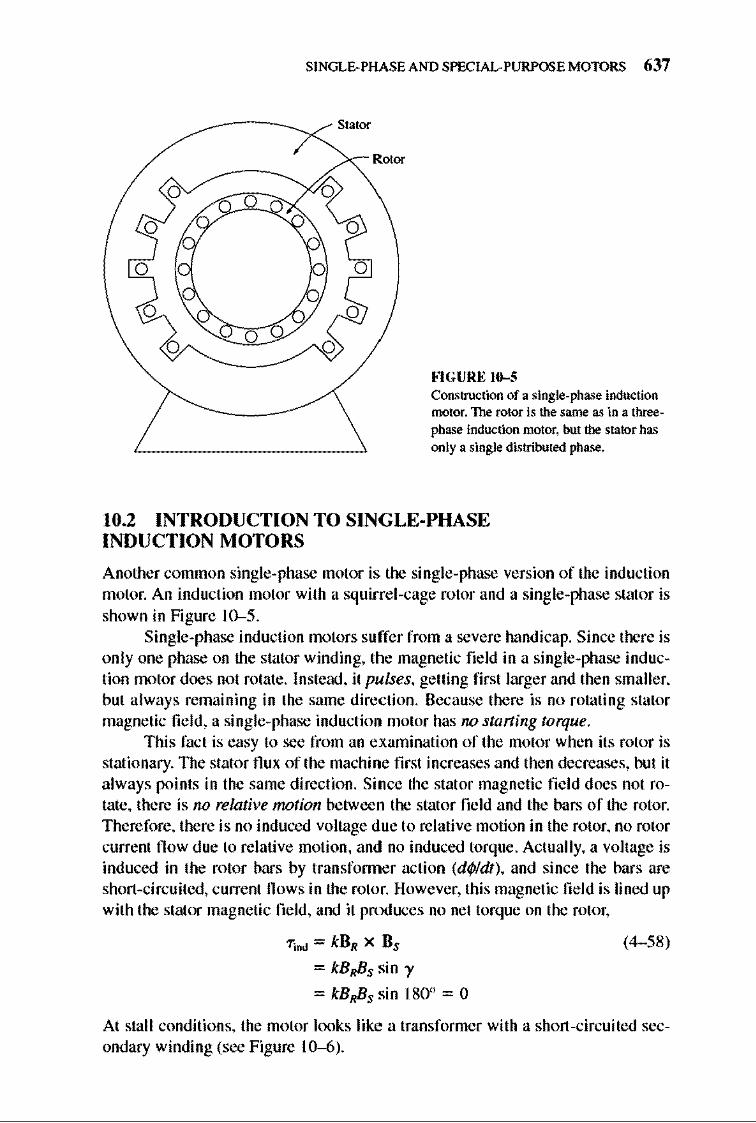
FlGURE 10-5 Construction of a single-phase induction motor. The rotor is the same as in a threephase induction motor. but the stator has only a single distributed phase.
10.2 INTRODUCTION TO SINGLE-PHASE INDUCTION MOTORS
Another common sing le-phase motor is the sing le-phase version of the induction motor. An induction motor with a squirre l-cage rotor and a single-phase stator is shown in Figure 10-5.
Single-phase induction motors suffer from a severe handicap. Since there is only one phase on the stator winding, the magnetic field in a single-phase induction motor does not rotate. Instead, it pulses, getting first larger and the n smaller, but a lways remaining in the same direction. Because the re is no rotating stator magnetic fie ld, a single-phase induction motor has no staning torque.
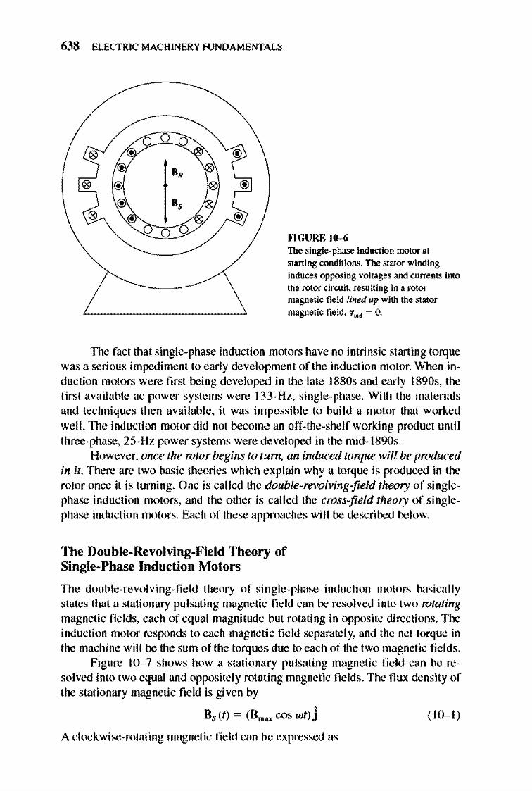
Thi s fact is easy to see from an examination of the motor when its rotor is stationary. The stator flu x of the machine first increases and then decreases, but it always points in the same di rection. Si nce the stat or magnetic fi e ld does not rotate, there is no relative motion between the stator field and the bars of the rotor. Therefore, there is no induced voltage due to relative motion in the rotor, no rotor current fl ow due to re lative motion, and no induced torque. Actually, a voltage is induced in the rotor bars by transfonner action (df/JIdt), and since the bars are short-circuited, current flows in the rotor. However, this magnetic fie ld is lined up with the stator magnetic field , and it produces no net torque on the rotor,
"rind = kBR X Bs
= kBRBS sin "y
= kBRBS sin 1800 = 0
(4- 58)
At stall conditions, the motor looks like a transformer with a short-circuited secondary winding (see Figure 10-6).
638 ELECTRIC MACHINERY RJNDAMENTALS
II,
FlGURE 10-6 The single-phase induction motor at starting conditions. The stator winding induces opposing voltages and currents into the rotor cirwit. resulting in a rotor magnetic field lined up with the stator magnetic field. 7;M = O.
TIle fact that single-phase induction motors have no intrinsic starting torq ue was a serious impedime nt to early development of the induction motor. When induction motors were first being developed in the late l880s and early 1890s, the first available ac power systems were 133-Hz, single-phase . With the materials and techniques then available, it was impossible to build a motor that worked well. The induction motor did not become an off-the-she lf working product until three-phase, 25- Hz power systems were developed in the mid- 189Os .
However, once the rotor begins to tum, an induced torque will be produced in it. TIlere are two basic theories which explain why a torque is produced in the rotor once it is turning. One is called the double-revolving-field theory of singlephase induction motors, and the other is called the cross-field theory of singlephase induction motors. E.1.ch of these approaches will be described below.
The Double-Revolving-Field Theory of Single-Phase Induction Motors
TIle double-revolving-field theory of single-phase induction motors basically states that a stationary pulsating magnetic field can be resolved into two rotating magnetic fields, each of equal magnitude but rotating in opposite directions. The induction motor responds to each magneti c field separate ly, and the net torque in the machine will be the sum of the torques due to each of the two magnetic fie lds .
Figure 10- 7 shows how a stationary pulsating magnetic field can be resolved into two equal and opposite ly rotating magnetic fields. The flu x density of the stationary magnetic field is given by
, Bs (t) = (Bmn cos wt) J
A clockwise-rotating magnetic field can be expressed as
( 10-1 )

0,
0- lie ...
/' " W W
(:1 )
", ,d,
FIGURE 10-7
SINGLE-PHASE AND SPECIAL-PURPOSE MOTORS 639
"-W
II,
,b,
", ,.,
"-W "- \ )
o-
W W
, "
( \ "ow 1--------1 "_
,f,
The resolution of a single pulsating magnetic field into two magnetic fields of equal magnitude by rotation in opposite directions. Notice that at all times the vector sum of the two magnetic fields lies in the vertical plane.
Bew(r) = (t Bmax cos wt)i - (t Bmax sin wi fi ( 10-2)
and a counlerc lockwise-rotating magnetic field can be expressed as
Bcew(t) = (1 Bmax cos wt)i + (1 Bmax sin wi fi ( 10-3)
Notice that the sum of the clockwise and counterclockwise magnetic fie lds is equal to the stationary pulsating magnetic field Bs:
8 ,(1) ~ B~(I) + BccwCt) (IO-d)
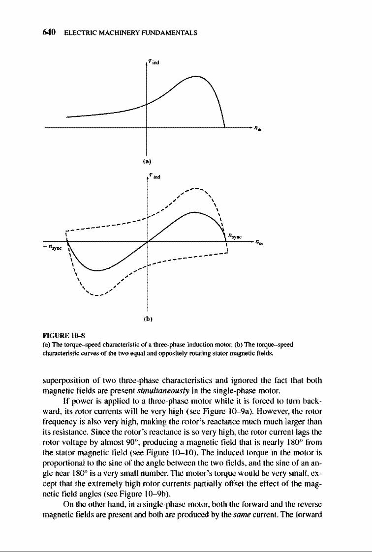
TIle torque-speed characteristic of a three-phase induction motor in response to it s single rotating magnetic field is shown in Figure 10--8a. A singlephase induction motor responds to each of the two magnetic fields present within it, so the net induced torque in the motor is the difference between the two torque- speed curves. This net torque is shown in Figure lO--8b. Notice that there is no net torq ue at zero speed, so this motor has no starting torque.
TIle torque- speed characteristic shown in Figure 1 0--8b is not quite an accurate description of the torque in a single-phase motor. It was formed by the
640 ELECTRIC MACHINERY RJNDAMENTALS
----------------------t----------------'------ '.
-----------
""GURE 10-8
,,' --, " ' , , , , , ,
-' , " , --- , ,
---------------
,b,
(a) The torque-speed characteristic of a three-phase induction motor. (b) The torque-speed characteristic curves of the two equal and oppositely rota.ting stator magnetic fields.
superposition of two three-phase characteristics and ignored the fact that both magnetic fields are present simultaneously in the single-phase motor.
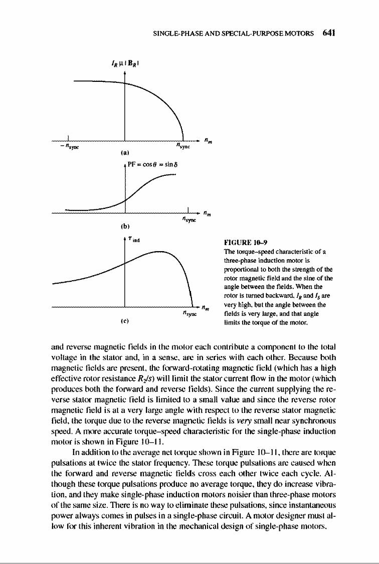
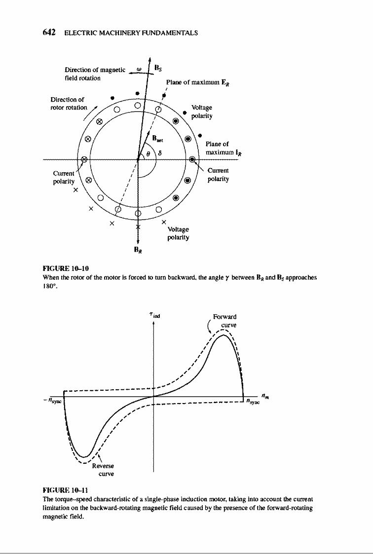
If power is applied to a three-phase motor while it is forced to turn backward, its rotor currents will be very high (see Figure 10--9a). However, the rotor frequency is also very high, making the rotor's reactance much much larger than its resistance. Since the rotor's reactance is so very high, the rotor current lags the rotor voltage by almost 900, pnxlucing a magnetic fi e ld that is nearly 180 0 from the stator magnetic field (see Figure 10- 10). The induced torque in the motor is proportional to the sine of the angle between the two fi e lds, and the sine of an angle near 1800 is a very small number. TIle motor 's torque would be very small, except that the extremely high rotor currents partially offset the effect of the magnetic field angles (see Figure 10- 9b).
On the other hand, in a single-phase motor, both the forward and the reverse magnetic fields are present and both are produced by the same current.llle forward
SINGLE-PHASE AND SPECIAL-PURPOSE MOTORS 641
- n,j'DC ,,' PF =cosfl =sinll
'. '.~ ,b,
fo'IGURE 10-9 The torque-speed characteristic of a three-phase induction motor is
proportional to both the strength of the rotor magnetic field and the sine of the angle between the fields. When the rotor is turned bad:waro. IN and Is are
'. very high. but the angle between the
'.~ fields is very large. and that angle
'0' limits the torque of the motor.
and reverse magnetic fields in the motor each contribute a component to the total voltage in the stator and, in a sense, are in series with each other. Because both magnetic fie lds are present, the forward-rotating magnetic field (which has a high effective rotor resistance Ris) will limit the stator current now in the motor (which produces both the forward and reverse fields). Since the current supplying the reverse stator magnetic fi e ld is limited to a small value and since the reverse rotor magnetic field is at a very large angle with respect to the reverse stator magnetic field, the torque due to the reverse magnetic fields is very small near synchronous speed. A more accurate torque-speed characteristic for the single-phase induction motor is shown in Figure 10-11.
In addition to the average net torque shown in Figure 10-11 , there are torq ue pulsations at twi ce the stator frequency. 1l1ese torque pulsations are caused when the forward and reverse magnetic fi e lds cross each other twice each cycle. Although these torque pulsations pnxluce no average torque, they do increase vibration, and they make single-phase induction motors noisier than three-phase motors of the same size. 1l1ere is no way to e liminate these pulsations, since instantaneous power always comes in pulses in a single-phase circuit. A motor designer must allow for this inherent vibration in the mechanical design of single-phase motors.
642 ELECTRIC MACHINERY RJNDAMENTALS
Direction of magnetic w 0, field rotation
Plane of maximum EI/ , • ~ Direction of •
rotor rotati0/-j 0 0 Voltage • ,
@ polarity
" , ,
" II .. , @ • Plane of , , maximum 11/
, Current
, Current , polarity " , @ polarity ,
X , 0
, @ ,
X , 0 X X
Voltage polarity
0,
""GURE 111-10 When the rotor of the motor is forced to turn backwmd. the angle r between 111/ and Bs approaches 180°.
1";00 Forward
.... ".".". "..
, ,
( CUn-ll ,-, , , , , , , , , , ,
/ '
----------------.--+=~-~¥-=----__+.c_ '. - n,}'DC _____ __ _________ n.y""
/'"..". .... -,
, , , , , , , ' \
, , , ,
'-' Reverse curve
""GURE III-II The torque--speed characteristic of a single-phase induction nx>toT. taking into account the current limitation on the backward-rotating magnetic field caused by the presence of the forward-rotating magnetic field.
SINGLE-PHASE AND SPECIAL-PURPOSE MOTORS 643
The Cross-Field Theory of Single-Phase Induction Motors
The cross-field theory of single-phase induction motors looks at the induction motor from a totally different point of view. 1l1is theory is concerned with the voltages and currents that the stationary stator magnetic fie ld can induce in the bars of the rotor when the rotor is moving.
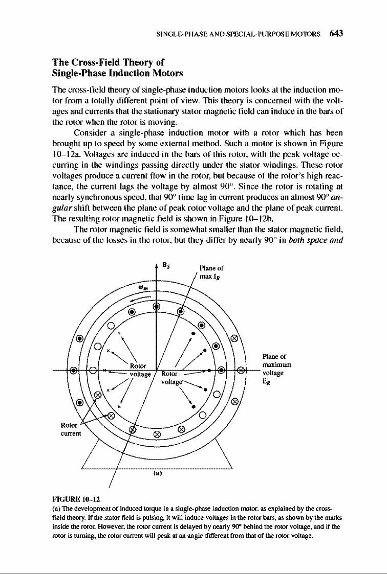
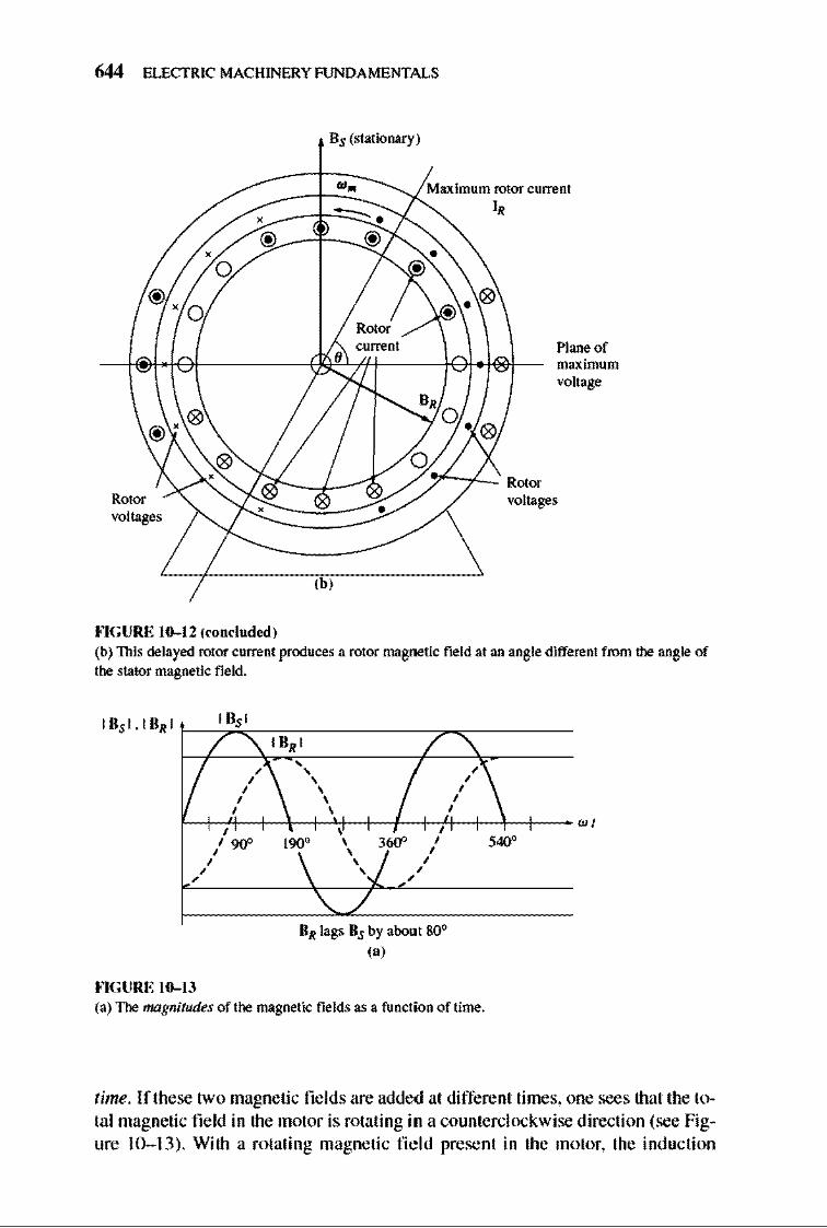
Consider a single-phase induction mot or with a rotor which has been brought up to speed by some externa l method. Such a motor is shown in Figure 1O-1 2a. Voltages are induced in the bars of this rotor, with the peak voltage occurring in the windings passing direct ly under the stator windings. 1l1ese rotor voltages produce a current now in the rotor, but because of the rotor's high reactance, the current lags the voltage by a lmost 90°. Since the rotor is rotating at nearly synchronous speed, that 90° time lag in current produces an almost 90° angular shift between the plane of peak rotor voltage and the plane of peak current. The resulting rotor magnetic field is shown in Figure 1O-1 2b.
The rotor magnetic field is somewhat smaller than the stator magnetic fi e ld, because of the losses in the rotor, but they differ by nearly 90° in both space and
current
FIGURE 10- 12
Plane of max IR
voltage-----....
\ ' ,
Plane of maximum . I
E,
(a) The development of induced torque in a single-phase induction nx>tor. as explained by the crossfield theocy. If the stator field is pulsing, it will induce voltages in the rot<r bars. as shown by the marks inside the rotor. Hoy/ever. the rotor current is delayed by nearly 90" behind the rotor voltage, and if the rotor is turning, the rotor current will peak at an angle different from that of the rotor voltage.
644 ELECTRIC MACHINERY RJNDAMENTALS
Bs (stationary)
w.
~ . Maximum rotor currem I,
• o @
'0
•
o
•
Plane of maximum voltage
/ ~:>"--r'-' Rmm Rotor volta.ges
""GURE 10-12 (concluded)
-~. voltages
(b'
(b) This delayed rotor current produces a rotor magoetic field at an angle different from the angle of the stator magnetic fie ld.
I I . I , / "'\ I URI /'\
/ , , , ,
""GURE 10-13
'\ " I , , , , , , , , , , ,
, 9<Y' 190\ \ )~ I , , , , , , , \.../
UR lags "5 by about 80 (a)
,
, , , , ,
(a) The magnitudes of the magnetic fields as a function of time.
w, ''''''
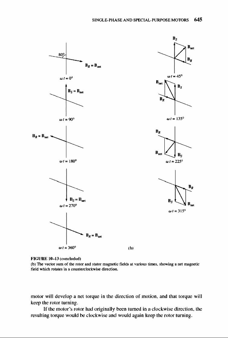
time. If these two magnetic fie lds are added at different times, one sees that the 10-tal magnetic field in the motor is rotating in a counterclockwise direction (see Figure 10- 13) . With a rotating magnetic fi e ld present in the motor, the induction
80'
",t=OO
",1=90°
wt= ISOo
lis = II .. ,
",t = 270°
wl=360°
FIGURE 10- 13 (conclud ... >d)
SINGLE-PHASE AND SPECIAL-PURPOSE MOTORS 645
II,
II,
,b,
wt=45°
wl= 135°
0,
"'t=225°
",t=315°
II .. ,
(b) The vector sum of the rotor and stator magnet ic fields at various times. showing a net magnetic field which rotates in a counterclockwise direction.
motor wi ll develop a net torque in the direction of motion, and that torque wi ll keep the rotor turning.
If the motor 's rotor had originally been turned in a clockwise direction, the resulting torq ue would be clockwise and would again keep the rotor turning.
646 ELECTRIC MACHINERY RJNDAMENTALS
10.3 STARTING SINGLE-PHASE INDUCTION MOTORS
As previously explained, a single-phase inducti on motor has no intrinsic starting torque. TIlere are three techniques commonly used to start these motors, and single-phase induction motors are classified according to the methods used to produce their starting torque. These starting techniques differ in cost and in the amount of starting torque produced, and an engineer normally uses the least expensive technique that meets the torque requirements in any given application. TIle three major starting techniques are
I. Split-phase windings
2. Capacitor-type windings
3. Shaded stator poles
All three starting techniques are methods of making one of the two revolving magnetic fi e lds in the motor stronger than the other and so giving the motor an initial nudge in one direction or the other.
Split-Phase Windings
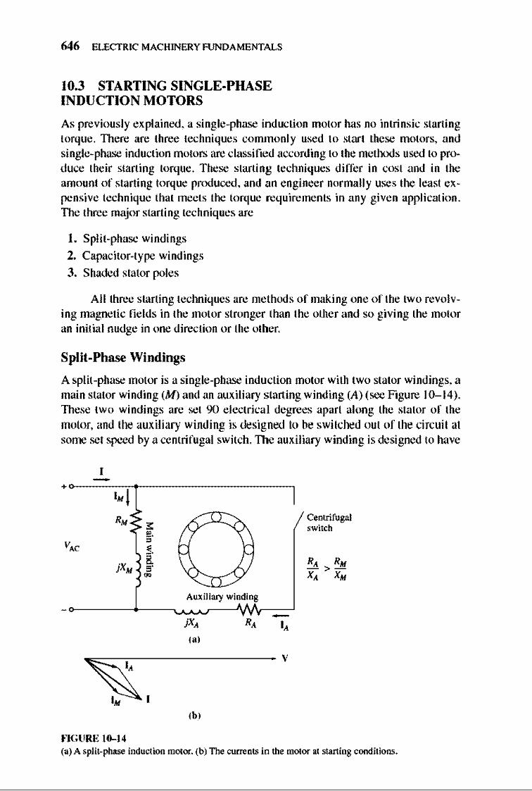
A split-phase motor is a single-phase indu ction motor with two stator windings, a main stator winding (M) and an auxiliary starting winding (A) (see Figure 10- 14) . TIlese two windings are set 90 electrica l degrees apart along the stator of the motor, and the auxiliary winding is designed to be switched oul of the circuit at some set speed by a centrifugal switch. TIle auxiliary winding is designed to have
+ 1· 1 R. < ,.
VAC , ~.
jXM a 5· ~
~ I. I
""GURE 10-14
Auxiliary winding
jX" R,
(a)
,b,
-I,
V
Centrifugal switch
(a) A split-phase induction motor. (b) The currents in the motor at starting conditions.

SINGLE-PHASE AND SPECIAL-PURPOSE MOTORS 647
a higher resistance/reactance ratio than the main winding, so that the current in the auxiliary winding leads the current in the main winding. This higher RIX ratio is usually accomplished by using smaller wire for the auxiliary winding. Smaller wire is pennissible in the auxiliary winding because it is used only for starting and therefore does not have to take full current continuously.
To understand the function of the auxiliary winding, refer to Figure 10-15. Since the current in the auxi liary winding leads the current in the main winding,
300%
®
®
®
®
0
Line fvoItage
/,,-, ~_I,'/ / /" \ "-, /
, "-, , , ,
Main plus starting winding
,
200%~_""---100%
Main winding alone
FIGURE 10-15
". ®
0 0
,.,
'-, ,
,b,
,
,.,
Auxiliary winding
Main winding
0
II,
0
Centrifugal switch
, , , , ,
(a) Relationship of main and auxiliary magnetic fields. (b) I .. peaks before 1M • producing a net counterclockwise rotation of the magnetic fields. (c) The resulting torque-speed characteristic.

648 ELECTRIC MACHINERY RJNDAMENTALS
""GURE 10-16 Cutaway view of a split-phase motor. showing the main and auxiliary windings and the centrifugal switch. (Courtesy of Westinghouse Electric Corpomtion. )
the magnetic fie ld BA peaks before the main magnetic field BM . Since BA peaks first and then BM , Ihere is a net counterclockwise rotation in the magnetic field. In other words, the auxi liary winding makes one of the oppositely rotating stator magnetic fie lds larger than the other one and provides a net starting torque for the motor. A Iypicallorque-speed characteristic is shown in Figure 1O-I Sc.
A culaway diagram of a split-phase motor is shown in Figure 10-16. It is easy to see the main and auxiliary windings (the auxi liary windings are the smaller-diameler wires) and the cenlrifuga l switch that cuts the auxiliary windings oul of the circuit when the motor approaches operating speed.
Split -phase motors have a moderate starting torque with a fairly low starting current. They are used for applications which do not require very high starting torq ues, such as fans, blowers, and cenlrifugal pumps. 1lley are available for sizes in the fractional-horsepower range and are quite inexpensive.
I n a split-phase induction motor, the current in the auxiliary windings always peaks before the current in the main winding, and therefore the magnetic field from the auxiliary winding always peaks before the magnetic field from the main winding. The direction of rotation of the motor is detennined by whether the space angie of the magnetic field from the auxiliary winding is 90° ahead or 90° behind the angle of the main winding. Since that angle can be changed from 90° ahead to 90° behind just by switching the connections on the auxiliary winding, the direction of rotation of the nwtor can be reversed by switching the connections of the auxiliary winding while leaving the main winding's connections unchanged.

SINGLE-PHASE AND SPECIAL-PURPOSE MOTORS 649
+o---~--~-------------------,
1· 1 Centrifugal
R. i sWItch
C
Auxiliary winding
,,'
I.
'h' FIGURE 10- 17 (a) A capacitor-start induction motor. (b) Current .angles at starting in this motor.
Capacitor-Start Motors
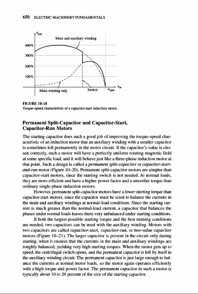
For some applications, the starting torq ue supplied by a split-phase motor is insufficient to start the load on a motor 's shaft. In those cases, capacitor-start motors may be used (Figure 10-1 7). In a capacitor-start motor, a capacitor is placed in series with the auxi liary winding of the motor. By proper selection of capacitor size, the magnetomoti ve force of the starting current in the auxiliary winding can be adjusted to be equal to the magnetomotive force of the current in the main winding, and the phase angle of the current in the auxi liary winding can be made to lead the current in the main winding by 90°. Since the two windings are physically separated by 90°, a 90° phase difference in current will yield a single unifonn rotating stator magnetic fie ld, and the motor will behave just as though it were starting from a three-phase power source. In this case, the starting torque of the motor can be more than 300 percent of its rated value (see Figure 10-1 8).
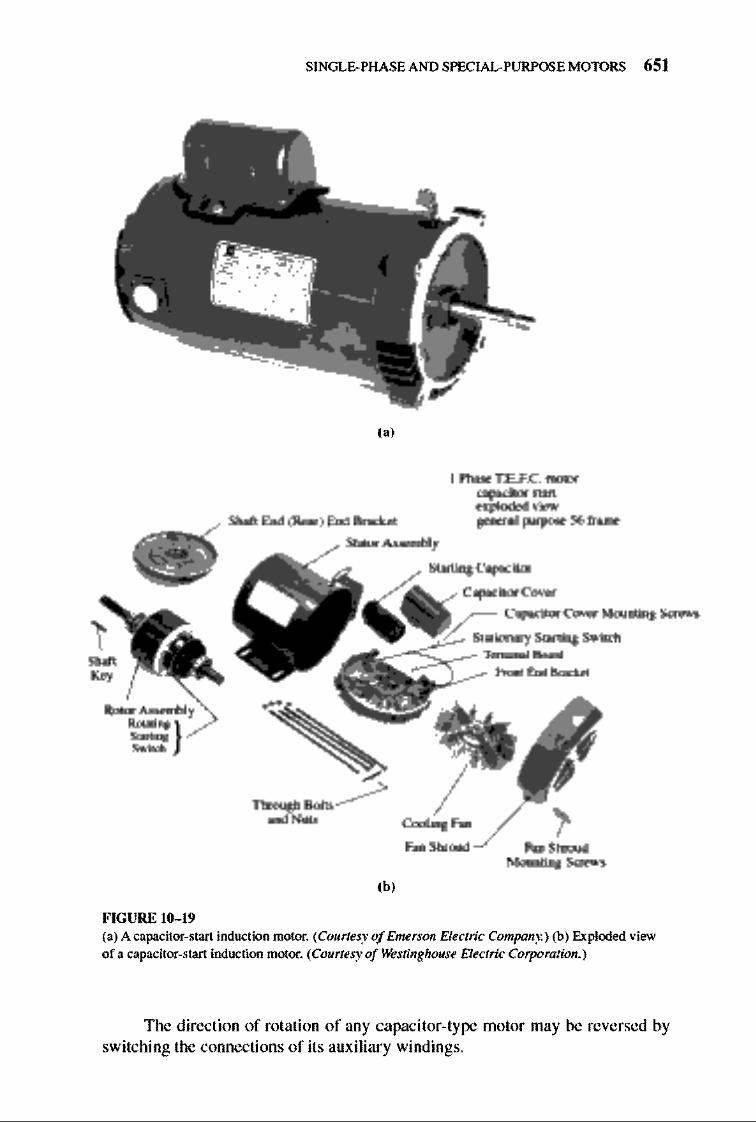
Capacitor-start motors are more expensive than split-phase motors, and they are used in applications where a high starting torque is absolutely required. Typical applications for such motors are compressors, pumps, air conditi oners, and other pieces of equipment that must start under a load. (See Figure 10-1 9.)
650 ELECTRIC MACHINERY RJNDAMENTALS
,~
400%
Main and aUXilip winding
V 300% , ,
~ ,
200%
'\ , , , , ,
100% ~ ,
,
~ ,
-(' , - ----- - -
Main winding only Switch ,~
""GURE 10-18 Torque-speed characteristic of a capacitor-start induction motor.
Permanent Split-Capacitor and Capacitor-Start, Capacitor-Run Motors
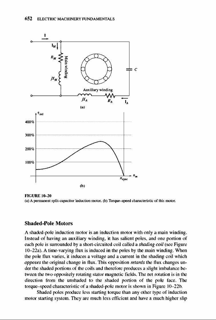
The starting capacitor does such a good jo b of improving Ihe torque-speed characteristic of an induction motor that an auxiliary winding with a smaller capacitor is sometimes left pennanently in the molo r circuit. If the capacitor's value is chosen correctly, such a motor will have a perfect ly unifonn rotating magnetic field at some specifi c load, and it will behave just like a three-phase inducti on motor at that point. Such a design is called a pennanent split-capacitor or capacitor-startand-run motor (Figure 10- 20). Pennane nt split-capacitor motors are simpler than capacitor-start motors, since the starting switch is not needed. At normal loads, Ihey are more effi cie nt and have a higher power factor and a smoother torque than ordinary single-phase induction motors.
However, pennanent split-capacitor molors have a lower starting torque Ihan capacitor-start motors, since the capacitor must be sized to balance lhe currents in the main and auxiliary windings at normal-load conditions. Since the starting current is much greater than the nonnal-load current, a capacitor that balances the phases under nonnal loads leaves them very unbalanced under starting conditions.
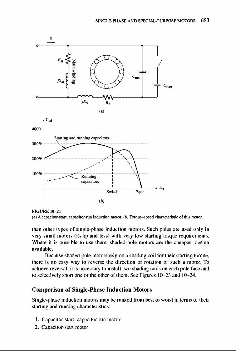
If both the largest possible starting lorque and the best running conditions are needed, two capacitors can be used with the auxiliary winding. Motors with two capacitors are called capacitor-stan, capacitor-run, or two-value capacitor motors (Figure 10- 2 1). TIle larger capacitor is present in the circuit only during starting, when it ensures that Ihe currents in the main and auxiliary windings are roughly balanced, yielding very high starting torques. When Ihe motor gets up 10
speed , the cenlrifugal switch opens, and the pennanent capacitor is left by itself in the auxi liary winding circuit. TIle pennanent capacitor is just large enough to balance the currents at nonnal motor loads, so the motor again operates efficienl ly with a high torque and power factor. TIle pennanent capacitor in such a motor is typically about 10 10 20 percent of the size of the starting capacitor.
Sh," !(oy
Rotor Assembly Rotllling } Staning Switch
FIGURE 10- 19
SINGLE-PHASE AND SPECIAL-PURPOSE MOTORS 651
('J
Shaft End (Rear) End Bracket
I Phase T.E.F.e. motor capa.citor start exploded view general purpose 56 frame
Stator Assembly
Starting Capacitor
Capacitor Cover
/ -- Capacitor Cover Mounting Screws
_~::::~;:-~Stationary Starting Switch ;: Tenninat Board
Front End Bmcket
Fan Shroud
(bJ
Fan Shroud Mounting Screws
(a) A capa.citor-start induction ntotor. (Courtesy of Emerson Electric Company.) (b) Exploded view of a capacitor-start induction motor. (Courtesy of Westinghouse Electric Corpomtion.)
The direction of rotation of any capacitor-type motor may be reversed by switching the connections of its auxiliary windings.
652 ELECTRIC MACHINERY RJNDAMENTALS
I. j
R. ~ ~ ~ < ,. , ~.
0 ~ C ~ , ~':l:/ jX. ~
Auxiliary win~i~g
jX, R, I, (a)
'00
400 %
300 %
100
% /' '" / \
% /' \
200
'.~
'h' ""GURE 10-20 (a) A permanent split-capacitor induction ntotor. (b) Torque-speed characteristic of this motor.
Shaded-Pole Motors
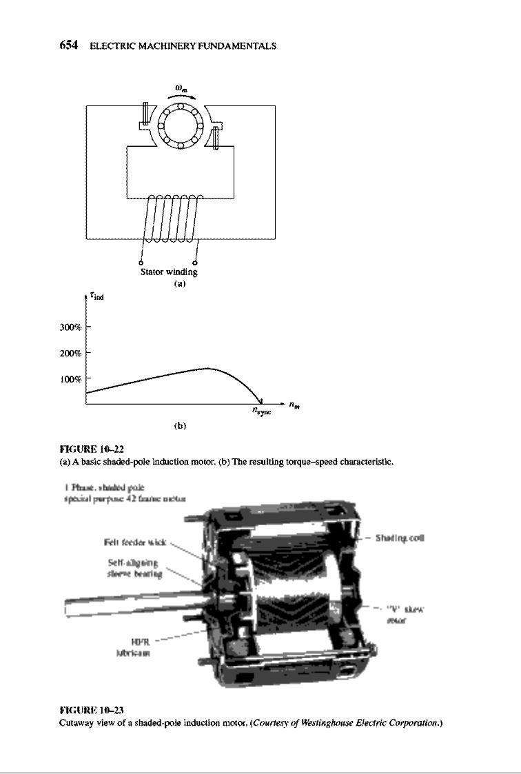
A shaded-pole induction motor is an indu ction molor with only a main winding. Instead of having an auxiliary winding, it has salient poles, and one portion of each pole is surrounded by a short-circuited coil called a shading coil (see Figure 1O- 22a). A time-varying flux is induced in Ihe poles by the main winding. When the pole flux varies, it induces a voltage and a current in the shading coil which opposes Ihe original change in flUX.1lli s opposition retards the flux changes under the shaded portions of the coils and therefore produces a slighl imbalance between Ihe two opposite ly rotating stator magnetic fields. TIle net rolation is in Ihe direction from the unshaded to the shaded portion of the pole face. The torque-speed characteristic of a shaded-po le molar is shown in Figure IO- 22b.
Shaded poles produce less starting torq ue than any other type of induction motor starting system. TIley are much less e ffi cient and have a much higher slip
SINGLE-PHASE AND SPECIAL-PURPOSE MOTORS 653
-~ ').
I RM < I' 7 '\ '\ ,.
" ~. := " c_ ~ " "" 5/ jXM
00 ,
(., fjmd
400 %
Starting and ru nning capacitors %
/ Y" \ % , , , , , , , , , , , ,
, , , ,
300
2llll
(00 % ,
_---<- Runmng , , , , --- capacitors , , , Switch "~
(b'
FIGURE 10- 21 (a) A capacitor-start. capacitor-run induction motor. (b) Torque-speed characteristic of this motor.
than other types of single-phase induction motors . Such poles are used only in very small motors (Y..o hp and less) with very low starting torque requirements. Where it is possible to use them, shaded-pole motors are the cheapest design available.
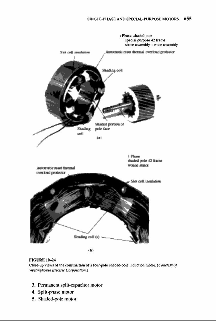
Because shaded-pole motors rely on a shading coil fo r their starting torque, there is no easy way to reverse the directi on of rotation of such a motor. To achieve reversal, it is necessary to install two shading coils on each pole face and to selecti vely short one or the other of them. See Figures 10-23 and 10- 24 .
Comparison of Single-Phase Induction Motors
Single-phase induction motors may be ranked from best to worst in tenns of their starting and running characteristics:
I. Capacitor-start , capacitor-run motor
2. Capacitor-start motor
654 ELECTRIC MACHINERY RJNDA MENTALS
300%
200%
Stator winding ,,'
"-------------------------~--- "m "."" ,b, ""GURE 10-22 (a) A basic shaded-pole induction motor. (b) The resulting torque-speed characteristic.
I Phase. shaded pole special purpose 42 frame motor
Self-aligning sleeve bearing
HFR -~~ lubricant
""GURE 10-23
Shading coil
"V" skew rotor
Cutaway view of a shaded-pole induction motor. (Courtesy ofWestin8lwuse Electric Corporation.)
SINGLE-PHASE AND SPECIAL-PURPOSE MOTORS 655
Slot cell insulation
Automatic reset thermal overload protector
I Phase. shaded pole special purpose 42 frame stator assembly + rotor assembly
,',moo.';",~, thennal overload protector
Shading coil
Shaded portion of pole face
(.,
I Phase shaded pole 42 frame wound stator
Slot cell insulation
Shading coil (5) ______ ~
(b'
FIGURE 10- 14 Close-up views of the construction of a four-pole shaded-pole induction motor. (Courtesy of Watinghouse Electric Corporation.)
3. Pennanent split-capacitor motor
4. Split-phase motor
S. Shaded-pole motor

656 ELECTRIC MACHINERY RJNDAMENTALS
Naturally, the best motor is also the most expensive, and the worst motor is the least expensive . Also, not all these starting techniques are avai lable in all motor size ranges. It is up to the design e ngineer to select the cheapest available motor for any given application that will do the job.
10.4 SPEED CONTROL OF SINGLE-PHASE INDUCTION MOTORS
In general, the speed of sing le-phase induction motors may be controlled in the same manner as the speed of polyphase induction motors. For squirrel-cage rotor motors, the foll owing techniques are available :
I. Vary the stator freque ncy.
2. Change the number of poles.
3. Change the applied tenninal voltage VT .
In practical designs involving fairly high-slip motors, the usual approach to speed control is to vary the terminal vo ltage of the motor. 1lle voltage applied to a motor may be varied in one of three ways :
I. An autotransformer may be used to continually adjust the line voltage. nlis is the most expensive methexl of voltage speed control and is used only when very smooth speed control is needed.
2. An SCR or TRIAC circuit may be used to reduce the nns voltage applied to the motor by ac phase control. nlis approach chops up the ac wavefonn as described in Chapter 3 and somewhat increases the motor's noise and vibration. Solid-state control circuits are considerably cheaper than autotransfonners and so are becoming more and more common.
3. A resistor may be inserted in series with the motor's stator circuit. This is the cheapest methexl of voltage control , but it has the disadvantage that considerable power is lost in the resistor, reducing the overall power conversion efficiency.
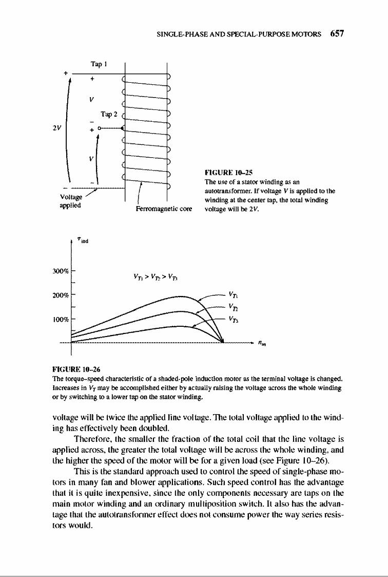
Another technique is also used with very high-slip motors such as shadedpole motors. Instead of using a separate a ut otransformer to vary the voltage applied to the stator of the motor, the stator winding itself can be used as an autotransfonner. Figure 10--25 shows a sche matic representati on of a main stator winding, with a number of taps along its length. Since the stator winding is wrapped about an iron core, it behaves as an autotransfonner.
When the full line voltage V is applied across the entire main winding, then the induction motor operates normally. Suppose instead that the full line voltage is applied to tap 2, the center tap of the winding.1lle n an identical voltage will be induced in the upper half of the winding by transformer action, and the total winding
Tap I +
+
V
-2V +
V
oltage /" V
apphed
300%
2llll%
100%
FIGURE 10-26
T", 2
SINGLE-PHASE AND SPECIAL-PURPOSE MOTORS 657
Ferromagnetic core
Jo'I GURE 10-25 The use of a stator winding as an autotransformer. If voltage V is applied to the winding at the center tap. the total winding voltage will he 2V.
~~ _ _____ ~_ Vo
Vo
Vo
The torque-speed characteristic of a shaded-pole induction motor as the terminal voltage is changed. Increases in VTmay he accomplished either by actually raising the voltage across the whole winding or by switching to a lower tap on the stator winding.
voltage will be twice the applied line voltage.1lle total voltage applied to the winding has effectively been doubled.
Therefore, the smaller the fraction of the total coil that the line voltage is applied across, the greater the total voltage will be across the whole winding, and the higher the speed of the motor wi ll be for a given load (see Figure 10- 26).
This is the standard approach used to control the speed of single-phase motors in many fan and blower applications. Such speed control has the advantage that it is quite inexpensive, since the only components necessary are taps on the main motor winding and an ordinary multiposition switch. It also has the advantage that the autotransformer effect does not consume power the way series resistors would.
658 ELECTRIC MACHINERY RJNDAMENTALS
10.5 THE CIRCUIT MODEL OF A SINGLE-PHASE INDUCTION MOTOR
As previously described, an understanding of the induced torque in a single-phase induction motor can be achieved through either the double-revolving-field theory or the cross-fi e ld theory of single-phase motors. Either approach can lead to an equi vale nt circuit of the motor, and the torque-speed characteristic can be derived through either method.
TIlis section is restricted to an examination of an equi valent circuit based on the double-revolving-field theory- in fact, to only a special case of that theory. We will devel op an equivalent circuit of the main winding of a single-phase induction motor when it is operating alone. The technique of symmetrica l components is necessary to analyze a single-phase motor with both main and auxiliary windings present, and since symmetrical components are beyond the scope of this book, that case will not be discussed. For a more detailed analysis of single-phase motors, see Reference 4.
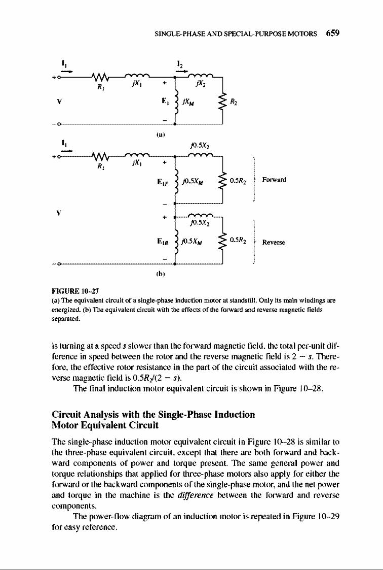
TIle best way to begin the analysis of a single-phase induction motor is to consider the motor when it is stalled. At that time, the motor appears to be just a single-phase transfonner with its secondary circuit shorted out, and so its equi valent circuit is that of a transformer. Thi s equivalent circuit is shown in Figure 100027a. In this fi gure, Rl and Xl are the resistance and reactance of the stator winding, XM is the magnetizing reactance, and Rl and X2 are the referred values of the rotor's resistance and reactance. The core losses of the machine are not shown and will be lumped together with the mec hanical and stray losses as a part of the motor's rotational losses.
Now recall that the pulsating air-gap flu x in the motor at stall conditions can be resolved into two equal and opposite magnetic fi e lds within the motor. Since these fie lds are of equal size, each one contributes an equal share to the resistive and reactive volt age drops in the rotor c ircuit. It is possible to split the rotor equivalent circuit into two sections, each one corresponding to the e ffects of one of the magnetic fi e lds. The motor equi valent circuit with the effects of the forward and reverse magnetic fie lds separated is shown in Figure 10--27b.
Now suppose that the motor 's rotor begins to turn with the help of an auxiliary winding and that the winding is switched out again after the motor comes up to speed. As derived in Chapter 7, the effective rotor resistance of an induction motor depends on the amount of relati ve motion between the rotor and the stator magnetic fie lds. However, there are two magnetic fi e lds in this motor, and the amount of relative motion differs for each of them.
For the fOlward magnetic field , the per- unit difference between the rotor speed and the speed of the magnetic field is the slip s, where slip is defined in the same manner as it was for three-phase induction motors. The rotor resistance in the part of the circuit associated with the forward magnetic fie ld is thus O.5R.Js.
TIle forward magnetic field rotates at speed n.ync and the reverse magnetic field rotates at speed -n.ync. TIlerefore, the total per-unit difference in speed (on a base of n.ync) between the forward and reverse magnetic fields is 2. Since the rotor
SINGLE-PHASE AND SPECIAL-PURPOSE MOTORS 659
I , I , - -+ R, j X ] + jX2
V E , jXM R,
(a) I, -+
R, jX] +
E" jO.5XM 0.5R2 Forward
-
V + jO.5X2
E" jO.5XM ~ 0.5R2 Reverse
-
,b, FIGURE 10-27 (a) The equivalent circuit of a single-phase induction motor at standstill. Only its main windings are energized. (b) The equivalent circuit with the effects of the forward and reverse magnetic fields separated.
is turning at a speed s slower than the forward magnetic field, the total per-unit difference in speed between the rotor and the reverse magnetic field is 2 - s. Therefore, the effective rotor resistance in the part of the circuit associated with the reverse magnetic field is 0.SRI(2 - s).
The final induction motor equivalent circuit is shown in Figure 10- 28 .
Circuit Analysis with the Single-Phase Induction Motor Equi valent Circuit
The single-phase induction motor equivalent circuit in Figure 10- 28 is similar to the three-phase equivalent circuit, except that there are both forward and backward components of power and torque present. 1lle same general power and torque relationships that applied for three-phase motors also apply for either the forward or the backward components or the single-phase motor, and the net power and torq ue in the machine is the difference between the forward and reverse components.
The power-now diagram of an induction motor is repeated in Figure 10- 29 for easy reference .
660 ELECTRIC MACHINERY RJNDAMENTALS
R, + " +
E lF O.5ZF jO.5XM 0.5 R2 Forward ,
-
V +
jO.5X2
E IB 0.5ZB jO.5XM 0.5 R2 Reverse 2->
-
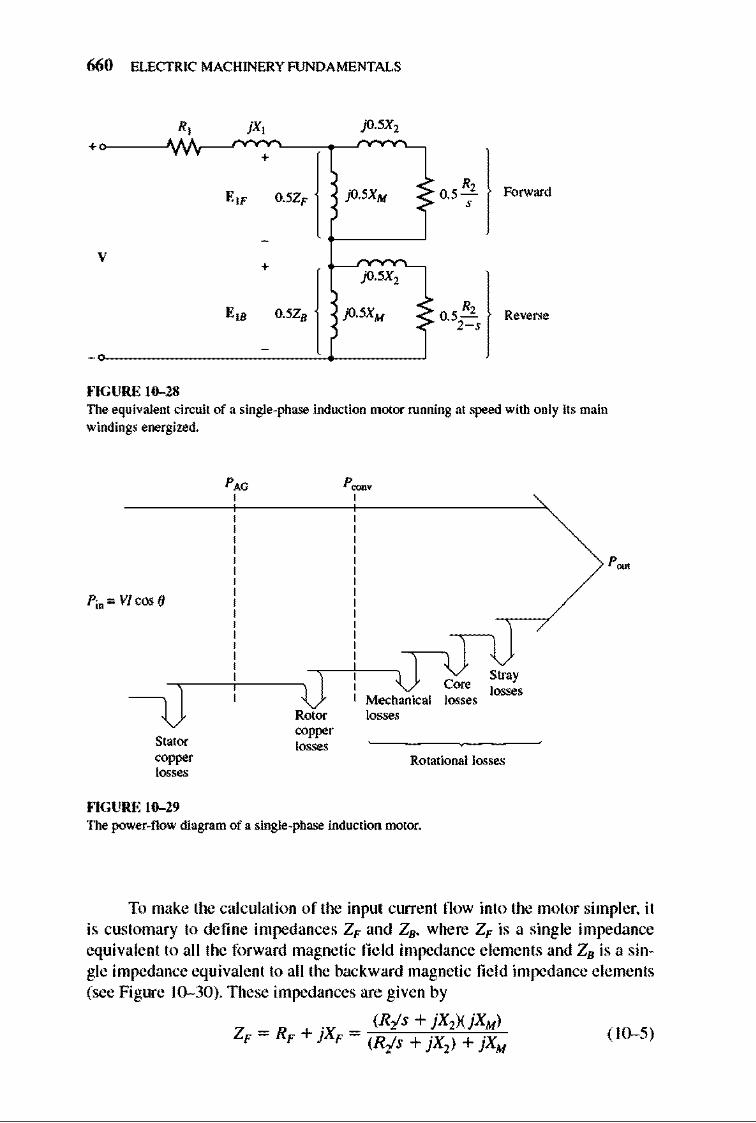
""GURE 10-28 The equivalent cin:uit of a single-phase induction motor running at speed with only its main windings energized.
Slator 00_ losses
""GURE 10-29
Rotor copper losses
Core Mechanical losses losses
Stray losses
Rotational losses
The power-flow diagram of a single-phase induction motor.
To make Ihe calculalion of the input current fl ow into the motor simpler, it is customary to define impedances ZF and ZB, where ZF is a single impedance equivalent to all the forward magnetic fi e ld impedance elements and ZB is a single impedance equivalent to all the backward magnetic fie ld impedance e lements (see Figure 10-30). These impedances are given by
. (Ris + jX.0(jXM) ZF = RF + }XF = (Ris + jX
2) + jXM ( 10-5)
-+
z, v
-+
z, V
D
SINGLE-PHASE AND SPECIAL-PURPOSE MOTORS 661
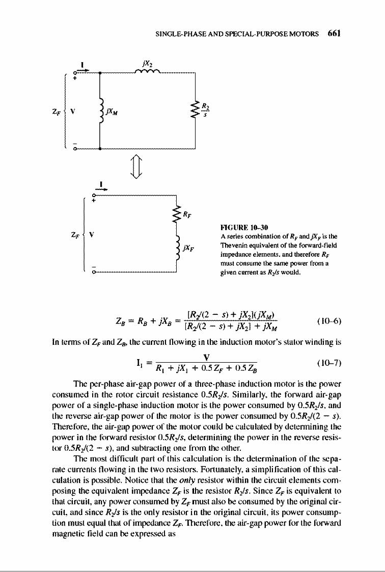
Fl G URE 10-30 A series oombination of RF andJXF is the
jXp Thevenin equivalent of the forwaJd-field impedance elements. and therefore Rr must consume the same power from a given current as Rlls would.
. [RI(2 - s) + jX2](jXM) ZB = RB + JXB = [R2/(2 s) + jX21 + jXM ( 10-<5)
In tenns of Zp and ZB, the current fl owing in the induction motor's stator winding is
( 10-7)
The per-phase air-gap power of a three-phase induction motor is the power consumed in the rotor circuit resistance O.5RJs. Simi larly, the forward air-gap power of a single-phase inducti on motor is the power consumed by 0.5R2/s, and the reverse air-gap power of the motor is the power consumed by O.5RJ(2 - s). Therefore, the air-gap power of the motor could be calculated by detennining the power in the forward resistor O.5RJs, detennining the power in the reverse resistor 0.5Ri(2 - s), and subtracting one from the other.
TIle most difficult part of this calculation is the determination of the separate currents fl owing in the two resistors. Fortunately, a simplification of this calculation is possible. Notice that the only resistor within the circuit elements composing the equivalent impedance Zp is the resistor Ris . Since Zp is equivalent to that circuit, any power consumed by ZF must also be consumed by the original circuit, and since Ris is the only resistor i n the original circuit , its power consumption must equal that ofimpedancc Zp. Therefore, the air-gap power for the forward magnetic fie ld can be expressed as

662 ELECTRIC MACHINERY RJNDAMENTALS
( 10-8)
Similarly, the air-gap power for the reverse magnetic fie ld can be expressed as
PAGJJ = n(0.5 RB) ( 10--9)
1lle advantage of these two equations is that only the one current / 1 needs to be calculated to detennine both powers.
TIle total air-gap power in a single-phase induction motor is thus
(10-10)
TIle induced torque in a three-phase induction motor can be found from the equation
PAG Tind = -
w,"" where PAG is the net air-gap power given by Equati on (10-10).
(10-11 )
1lle rotor copper losses can be fou nd as the sum of the rotor copper losses due to the forward fie ld and the rotor copper losses due to the reverse fi e ld.
(10- 12)
TIle rotor copper losses in a three-phase induction motor were equal to the perunit relative motion between the rotor and the stator field (the slip) times the airgap power of the machine. Similarly, the forward rotor copper losses of a singlephase induction motor are given by
P RCL•F = SPAG•F (10- 13)
and the reverse rotor copper losses of the motor are given by
(10-14)
Since these two power losses in the rotor are at different frequencies, the total rotor power loss is just their sum.
TIle power converted from electrical to mechanical fonn in a single-phase induction motor is given by the same equation as P.:OD¥ for three-phase induction motors. TIlis equation is
Since Wm = (1 - s)w. ync, this equation can be reexpressed as
PC<JJI¥ = Tind(1 - s)wm
From Equation (10-11 ), PAG = TiDdW, y .. ,,, so P.:oo¥ can also be expressed as
P.:ODV = ( I - s) PAG
(10-15)
(10-16)
(10-17)
As in the three-phase induction motor, the shaft output power is not equal to P.:OD¥' since the rotational losses must still be subtracted. In the single-phase induction motor model used here, the core losses, mechanical losses, and stray losses must be subtracted from P.:ODV in order to get POll '.
SINGLE-PHASE AND SPECIAL-PURPOSE MOTORS 663
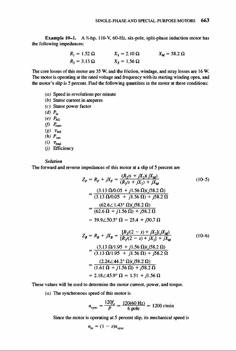
Example 10-1. A ~hp, lID-V, 60-Hz, six-pole, split-phase induction motor has the following impedances:
R] = 1.52Q
R2 = 3.13 Q
X ] =2.100
Xl = 1.56Q
XM = 58.2 Q
The core losses of this motor are 35 W, and the friction, windage, and stray losses are 16 W. The motor is operating at the rated voltage and frequency with its starting winding open, and the motor 's slip is 5 percent. Find the following quantities in the motor at these conditions:
(a) Speed in revolutions per minute (b) Stator current in amperes (c) Stator power factor (d) Pin (e) PAG
(f) P_ (g) "TiOO
(h) P "'" (i) "Tj.,.;l
0) Efficiency
Solution The forward and reverse impedances of this motor at a slip of 5 percent are
_ . _ (Ris + jx.zXjXM) ZF - RF + }XF - (Ris + jX2) + jXM
(3.13 flAI.05 + jl.56 0)(j58.2 0) = (3.13 OAI.05 + jl.56 0) + j58.2 0
(62.6L 1.430 OXj5S.2 0) = (62.60 + jl.56 0) + j5S.2 0
= 39.9L50.5° 0 = 25.4 + j30.7 0
_ . _ [Rf(2 - s) + jX2](jXM) ZB - RB + }XB - [Rf(2 s) + jX2] + jXM
(3.13 fl/1.95 + jl.56 0)(j58.2 0) = (3.13 fl/1.95 + jl.56 0) + j58.2 0
(2.24L44.2° OXj5S.2 0) = (1.61 0 + jl.56 0) + j5S.2 0
= 2.ISL45.9° 0 = 1.51 + jl.56 0
These values will be used to detennine the motor clUTent, power, and torque.
(a) The synchronous speed of this motor is
II = 12Qf, = 120(60 Hz) = .ync P 6 pole 1200 r/min
Since the motor is operating at 5 percent slip, its mechanical speed is
11m = (I - s)n~yDC
(10-5)
(10--6)
664 ELECTRIC MACHINERY RJNDAMENTALS
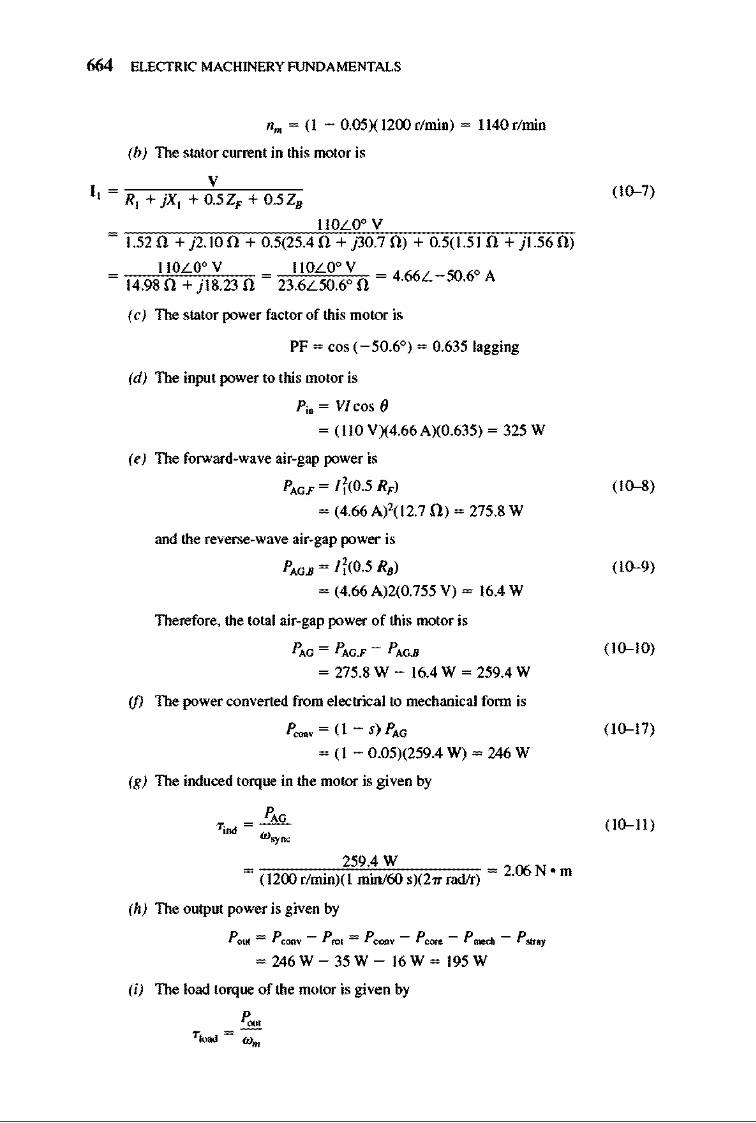
n .. = (I - 0.05X 1200 r/min) = 1140 r/min
(b) The stator current in this motor is
"">CCC,"or,",,<o"".i~i~O~L~O,""V~"'C-"'7<""C-"'CC"" = 1.52 n + j2.10 n + 0.5(25.4 n + j30.7 n) + 0.5(1.51 n + j1.56 n)
= .""i'iii'0,;L,O"",,VCcon - lIOLO° V _ 466L 50 6° A 14.98 n + jI8.23 n - 23.6L50.6° n - . - .
(c) The stator power factor of this motor is
PF = cos ( - 50.6°) = 0.635 lagging
(d) The input power to this motor is
Pm = VI cos ()
= (110 VX4.66 AXO.635) = 325 W
(e) The forward-wave air-gap power is
PAGE = l i(o.5 RF)
= (4.66 A)2(12.7 0) = 275.8 W
and the reverse-wave air-gap power is
PAG.B = l i(o.5 RB)
= (4.66 A)2(0.755 V) = 16.4 W
Therefore, the total air-gap power of this motor is
PAG = PAG.F - PAG.B
= 275.8 W - 16.4 W = 259.4 W
if) The power converted from electrical to mechanical fonn is
P OO<IV = (I - s) PAG
= (I - 0.05)(259.4 W) = 246 W
(g) The induced torque in the motor is given by
= 259.4 W = 2(x;N o (1200r/min)(lminJ60sX27Tradlr) . m
(h) The output power is given by
POlS. = Pooov - P~ = Pooov - POOle - PIDOCb - P_ y
= 246 W - 35 W - 16 W = 195 W
(i) The load torque of the motor is given by
p~ T_ = w".
(10--7)
(10--8)
(10-9)
(10--10)
(10--17)
(10--11 )
SINGLE-PHASE AND SPECIAL-PURPOSE MOTORS 665
= 195W = 163N o (1140 r/minXI min/60 s)(21Tradlr) . m
OJ Finally, the efficiency of the motor at these conditions is
195 W 100% = 325 W x 100% = 60%
10.6 OTHER TYPES OF MOTORS
Two other types of motors- reluctance motors and hysteresis motors-are used in certain special-purpose appli cations . These motors differ in rotor constructi on from the ones previously described, but use the same stator design. Like induction motors, they can be built with either sin gle- or three-phase stators. A third type of special-purpose motor is the stepper motor. A stepper motor requires a polyphase stator, but it does not require a three-phase power supply. The final specialpurpose motor discussed is the brushless dc motor, which as the name suggests runs on a dc power supply.
Reluctance Motors
A reluctance motor is a motor which depends on reluctance torque for its operation. Reluctance torque is the torque induced in an iron object (such as a pin) in the presence of an external magnetic field , which causes the object to line up with the external magnetic fie ld. TIli s torque occurs because the external field induces an internal magnetic field in the iron of the object, and a torque appears between the two fie lds, twisting the object around to line up with the external field. In order for a reluctance torque to be produced in an object, it must be elongated along axes at angles corresponding to the angles between adjacent poles of the external magnetic fi e ld.
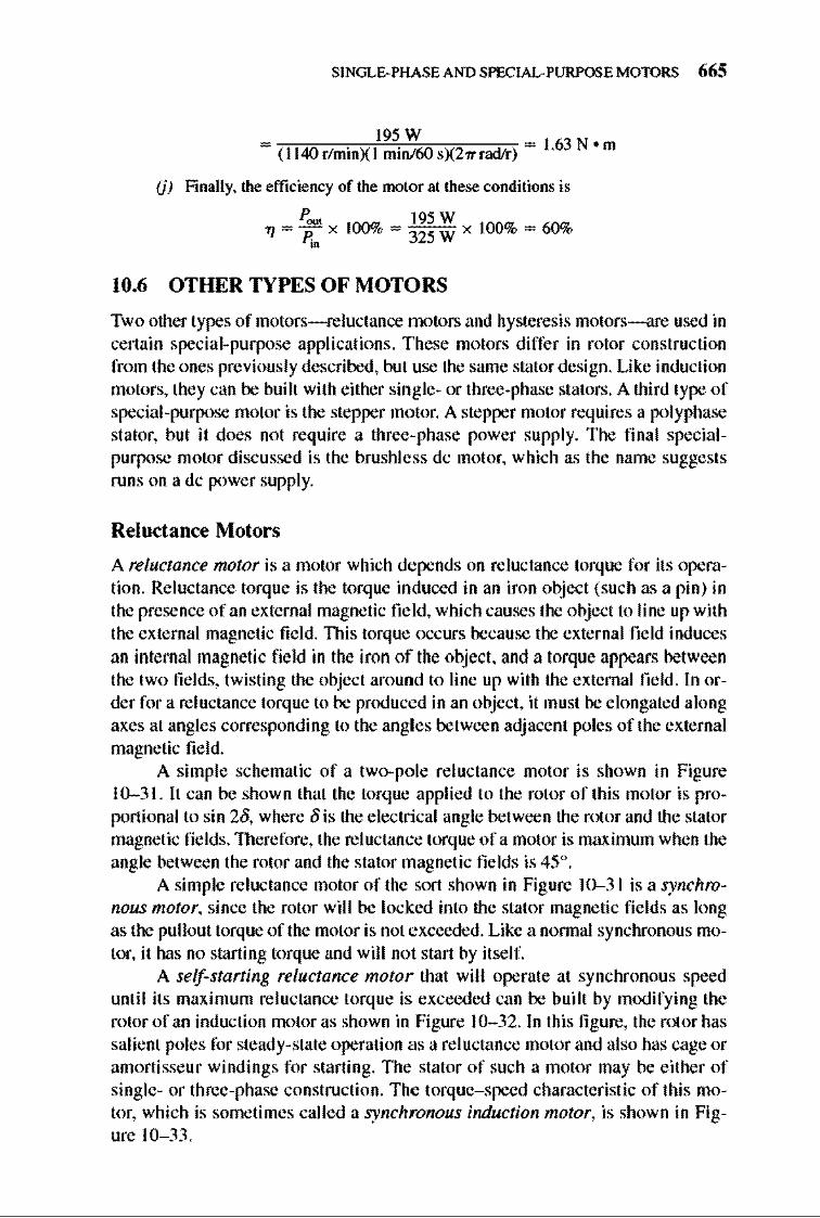
A simple schematic of a two-pole re luctance motor is shown in Figure 1O-3 \. It can be shown that the torque applied to the rotor of this motor is proportional to sin 20, where 0 is the electrical angle between the rotor and the stator magnetic fields. TIlerefore, the reluctance torque ofa motor is maximum when the angle between the rotor and the stator magnetic fields is 45 °.
A simple reluctance motor of the sort shown in Figure 10-3 I is a synchronous motor, since the rotor will be locked into the stator magnetic fie lds as long as the pullout torque of the motor is not exceeded. Like a nonnal synchronous motor, it has no starting torque and will no t start by it self.
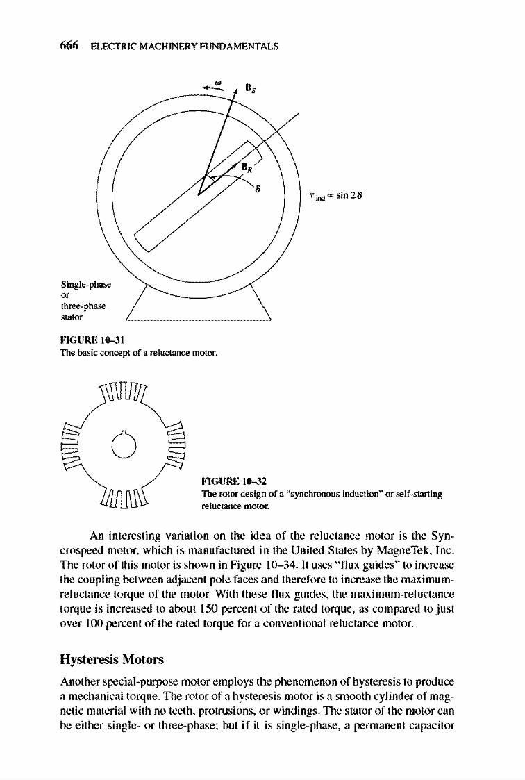
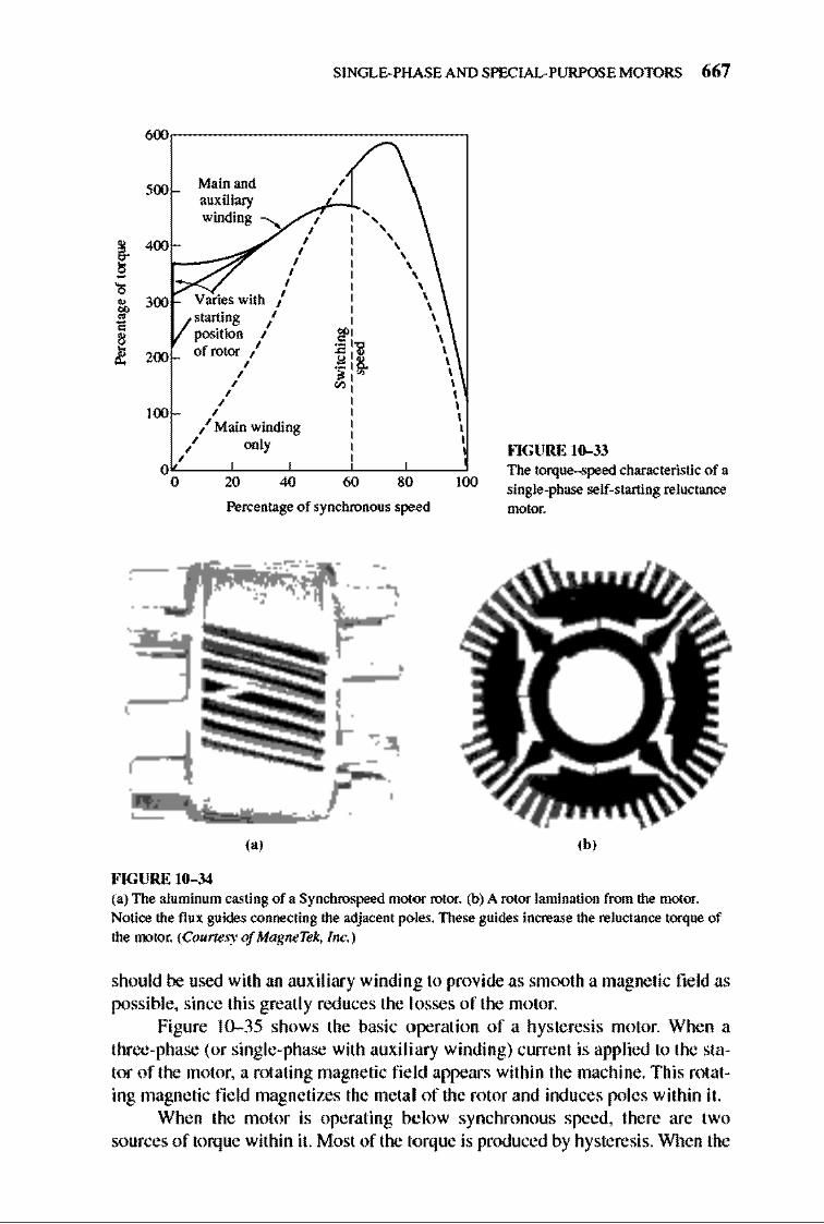
A self-starting reluctance motor that will operate at sy nchronous speed until its maximum reluctance torque is exceeded can be built by modifying the rotor of an induction motor as shown in Figure 10- 32. In this fi gure, the rotor has salient poles for steady-state operati on as a re luctance motor and also has cage or amortisseur windings for starting. TIle stator of such a motor may be e ithe r of single- or three-phase construction. The torque- speed characteristic of this motor, which is sometimes called a synchronous induction motor, is shown in Figure 10-33.
666 ELECTRIC MACHINERY RJNDAMENTALS
Single-phase 0' three-phase stator
""GURE 10-31
, "iDd""sin2/i
The basic concept of a reluctance motor.
o FIGURE 10-32 The rotor design of a "synchronous induction" or self-starting reluctance motor.
An inleresting variation on Ihe idea of Ihe reluctance motor is Ihe Syncrospeed motor, which is manufactured in the United States by MagneTek, Inc . TIle rotor of this motor is shown in Figure 10- 34. It uses " flux guides" to increase Ihe coupling between adjacenl pole faces and therefore to increase the maximumre luctance lorque of the motor. With these flux guides, Ihe maximum-re luctance torque is increased to about 150 percent o f the rated torque, as compared to just over 100 percent of the rated torque for a conve ntional reluctance motor.
Hysteresis Motors
Another special-purpose motor employs the phenomenon of hysteresis to produce a mechanical lorque . TIle rotor of a hysteresis motor is a smoolh cylinder of magnetic material with no teeth, protrusions, or windings. TIle stator of the motor can be either single- or three-phase; but if it is single-phase, a permanent capacitor
SINGLE-PHASE AND SPECIAL-PURPOSE MOTORS 667
~,-------------~~---,
500
, 400
Main and auxiliary
, , winding I I "', , , , , , '
~ f--;;:; I I \ , , , , , , , , ,
Varies with / I \ , , starting I I \
position " ::? I \ of rotor " :c: :al \
I . .e! 12!.. \ I OJ I '"' \
" '" I \ , , , , , , " Main winding I \ , ,
" only I
200
100
, ,
O~--~--~--~--~--~ o 20 40 60 80 100
Percentage of synchronous speed
(a)
FIGURE 10-34
""GURE 10-33 The torque-speed characteristic of a single-phase self-starting reluctance ntotor.
'h' (a) The aluminum casting of a Synchrospeed motor rotor. (b) A rotor lamination from the motor. Notice the flux guides connecting the adjacent poles. These guides increase the reluctance torque of the motor. (Courtesy of MagneTek, I nc.)
should be used with an auxiliary winding to provide as smooth a magnetic field as possible, since this greatly reduces the losses of the motor.
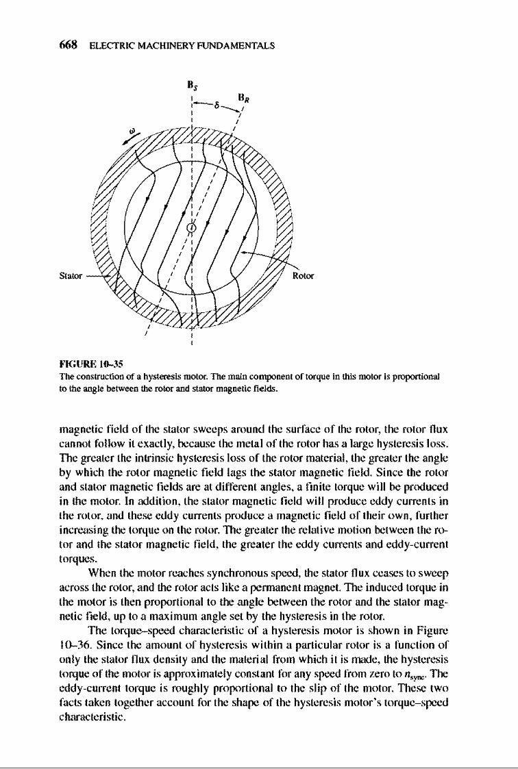
Figure 10-35 shows the basic operation of a hysteresis motor. Whe n a three-phase (or sing le-phase with auxi li ary winding) current is applied to the stator of the motor, a rotating magnetic fi e ld appears within the machine. This rotating magnetic fie ld magnetizes the meta l of the rotor and induces poles within it.
Whe n the motor is operating below synchronous speed, there are two sources of torq ue within it. Most of the torque is produced by hysteresis. When the
668 ELECTRIC MACHINERY RJNDAMENTALS
Stator - "6-}
""GURE 10-35
, ,
II, , 0, 1-6---..1 , , , ,
~777 ' ,
Rotor
The construction of a hysteresis motor. The main component of torque in this motor is proponional to the angle between the rotor and stator magnetic fields.
magnetic fie ld of the stator sweeps around the surface of the rotor, the rotor flux cannot follow it exactly, because the metal of the rotor has a large hysteresis loss . TIle greater the intrinsic hysteresis loss of the rotor material, the greater the angle by which the rotor magnetic field lags the stator magnetic field. Since the rotor and stator magnetic fields are at different angles, a fmite torque will be produced in the motor. In addition, the stator magnetic fi e ld will produce eddy current s in the rotor, and these eddy currents produce a magnetic field of their own, further increasing the torque on the rotor. TIle greater the relative motion between the rotor and the stator magnetic fi e ld, the greater the eddy currents and eddy-current torques.
When the motor reaches synchronous speed, the stator flux ceases to sweep across the rotor, and the rotor acts like a pennanent magnet. The induced torque in the motor is then proportional to the angle between the rotor and the stator magnetic field , up to a maximum angle set by the hysteresis in the rotor.
TIle torque-speed characte ristic of a hysteresis motor is shown in Figure 10--36. Since the amount of hysteresis within a particular rotor is a function of only the stator flux density and the material from which it is made, the hysteresis torque of the motor is approximately constant for any speed from zero to n,ync. The eddy-c urrent torque is roughly proportional to the slip of the motor. TIlese two facts taken together account for the shape of the hysteresis motor's torque-speed characteristic .

FIGURE 10-37
SINGLE-PHASE AND SPECIAL-PURPOSE MOTORS 669
""GURE 10-36 n.. The torque--speed characteristic
ofa motor.
A small hysteresis motor with a shaded-pole stator. suitable for running an electric clock. Note the shaded stator poles. (Stt'phen J. Chapman)
Since the torque of a hysteresis motor at any subsynchronous speed is greater than its maximum synchronous torque, a hysteresis motor can accelerate any load that it can carry during normal operation.
A very small hysteresis motor can be bui lt with shaded-pole stator construction to create a tiny self-starting low-power synchronous motor. Such a motor is shown in Figure 10- 37. It is commonly used as the driving mechanism in electric clocks. An electric clock is therefore synchronized to the line frequency of the power system, and the resulting clock is just as accurate (or as inaccurate) as the frequency of the power system to which it is tied.
670 ELECTRIC MACHINERY RJNDAMENTALS
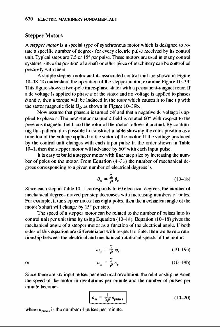
Stepper Motors
A stepper nwtor is a special type of synchronous motor which is designed to rotate a specifi c number of degrees for every e lectric pulse received by its control unit. Typical steps are 7.5 or 15° per pulse. 1llese motors are used in many control systems, since the position of a shaft or other piece of machinery can be controlled precisely with them.
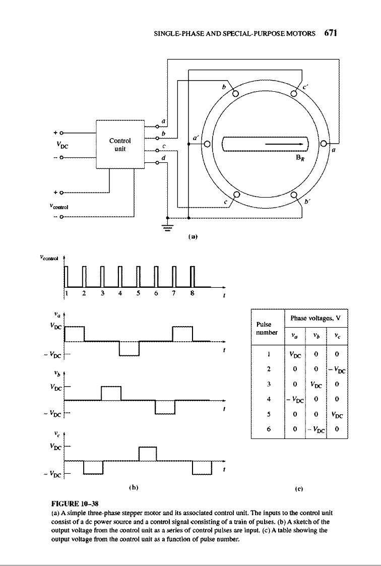
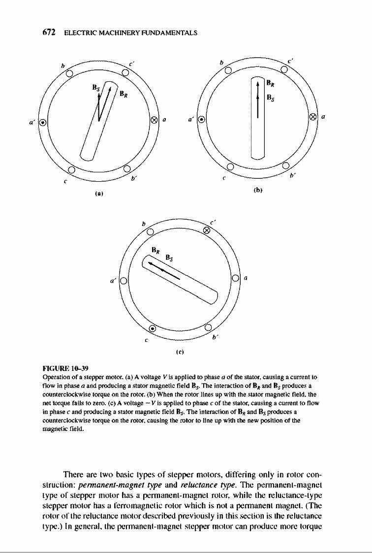
A simple stepper motor and its associated control unit are shown in Figure 1 0- 3S. To understand the operation of the stepper motor, examine Figure 10-39. TIlis fi gure shows a two-pole three-phase stator with a pennanent-magnet rotor. If a dc voltage is applied to phase a of the stator and no voltage is applied to phases band c, then a torque wi ll be induced in the rotor which causes it to line up with the stator magnetic field Bs, as shown in Figure 10--39b.
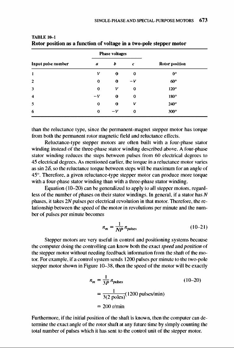
Now assume that phase a is turned o ff and that a negative dc voltage is applied to phase c. TIle new stator magnetic field is rotated 60° with respect to the previous magnetic field , and the rotor of the motor fo llows it around. By continuing this pattern, it is possible to construct a table showing the rotor position as a function of the voltage applied to the stator of the motor. If the voltage produced by the control unit changes with each input pulse in the order shown in Table 10-1, then the stepper motor will advance by 60° with each input pulse.
It is easy to bui ld a stepper motor with finer step size by increasing the number of poles on the motor. From Equation (4- 3 1) the number of mechanical degrees corresponding to a give n number of electrical degrees is
(10- 18)
Since each step in Table 10-1 corresponds to 60 electrical degrees, the number of mechanical degrees moved per step decreases with increasing numbers of poles. For example, if the stepper motor has eight poles, then the mechanical ang le of the motor's shaft will change by 15° per step.
1lle speed of a stepper motor can be related to the number of pulses int o its control unit per unit time by using Equation (10-IS). Equation (10-1S) gives the mechanical angle of a stepper motor as a function of the electrical angle . If both sides of this equation are differentiated with respect to time, then we have a relationship between the electrical and mechanical rotational speeds of the motor:
2 (1O-19a) wm = pW~
2 ( IO-19b) "' nm = p n~
Since there are six input pulses per electrical revolution, the relationship between the speed of the motor in revolutions per minute and the number of pulses per minute becomes
I nm = -iP npul ses ( 10- 20)
where n pulse< is the number of pulses per minute.
SINGLE-PHASE AND SPECIAL-PURPOSE MOTORS 671
b
" + b
Control "' ( ) Voc unit
, d B,
+~--~
( a)
1 2 3 4 , 6 7 8 ,
Voc 1---, Phase voltages. V
,"1~
number '. '. " 1 Voc 0 0
'. 2 0 0 - Voc
3 0 Voc 0
4 - Voc 0 0
5 0 0 Voc
6 0 - Voc 0
(b' ( " FIGURE 10-38 (a) A simple three-phase stepper motor and its associated control unit. The inputs to the control unit consist of a de power source and a control signal consisting of a train of pulses. (b) A sketch of the output voltage from the control unit as a series of control pulses are input. (e) A table showing the
output voltage from the control unit as a function of pulse number.
672 ELECTRIC MACHINERY RJNDAMENTALS
b
o B,
0,
" .
b'
('J (bJ
b c'
0 0
0, B,
.' ~ O·
b'
(cJ
""GURE 10-39 Operation of a stepper motor. (a) A voltage V is applied to phase a of the stator. causing a current to flow in phase a and producing a stator magnetic field ns. The interaction of nR and ns produces a counterclockwise torque on the rotor. (b) When the rotor lines up with the stator magnetic field. the net torque falls to zero. (c) A voltage - V is applied to phase c of the stator. causing a current to flow in phase c and producing a stator magnetic field ns. The interaction of DR and Ds produces a counterclockwise torque on the rotor. causing the rotor to line up with the new position of the magnetic field.
•
TIlere are two basic types of stepper motors, differing only in rotor construction: permanent-magnet l)pe and reluctance l)pe. TIle pennanent-magnet type of stepper motor has a permanent-magnet rotor, while the reluctance-type stepper motor has a ferromagnetic rotor which is not a pennanent magnet. (The rotor of the reluctance motor described previously in this section is the reluctance type.) In general, the pennanent-magnet stepper motor can produce more torq ue
SINGLE-PHASE AND SPECIAL-PURPOSE MOTORS 673
TABLE 10-1
Rotor positi on as a function of voltage in a two-pole stepper motor
Input pulse number
2
3
4
5
6
Phase ,·o ltaj!cs
" b
V 0
0 0
0 V
- V 0
0 0
0 - v
, Rotor position
0 0 °
- V 60°
0 120°
0 1SO°
V 240°
0 3lX1°
than the reluctance Iype, since the permanent-magnel stepper motor has lorque from both the pennanent rotor magnetic field and reluctance effects.
Reluctance-type stepper motors are often bui lt with a four-phase stator winding instead of the three-phase stator winding described above. A four-phase stator winding reduces the steps belween pulses from 60 electrical degrees to 45 e lectrical degrees. As menlioned earlier, the torque in a reluctance motor varies as sin 20, so the reluctance torque between steps will be maximum for an angle of 45°. Therefore, a given reluctance-type stepper motor can produce more torque with a four-phase stator winding than with a three-phase stator winding.
Equation ( 10- 20) can be generali zed to apply to all stepper motors, regardless of the number of phases on their stator windings. In general, if a stator has N phases, it takes 2N pulses per e lectrical revolution in thai motor. 1l1erefore, the relationship between the speed of the motor in revolutions per minute and the number of pulses per minute becomes
( 10- 21)
Stepper motors are very useful in control and positioning systems because the compuler doing the controlling can know both the exact speed and position of the stepper motor without needing feedback infonnation from the shaft of the motor. For example, if a control system sends 1200 pulses per minute 10 the two-pole stepper motor shown in Figure 10--38, then the speed of the motor will be exacl ly
- 3(2 ; oles}l 200 pulses/min)
= 200 r/rnin
(10- 20)
Furthennore, if the initial position of the shaft is known, then the computer can detennine the exact angle of the rotor shaft at any fulure time by simply counting the total number of pulses which it has sent to the control unit of the stepper motor.
674 ELECTRIC MACHINERY RJNDAMENTALS
Example 10-2. A three-phase permanent-magnet stepper motor required for one particular application must be capable of controlling the position of a shaft in steps of 7.5°, and it must be capable of running at speeds of up to 300 r/min.
(a) How many poles must this motor have? (b) At what rate must control pulses be ra:eived in the motor's control unit if it is to
be driven at 300 r/min?
Solutioll (a) In a three-phase stepper motor, each pulse advances the rotor's position by
60 electrical degrees. This advance must correspond to 7.5 ma:hanical degrees. Solving Equation (10--18) for P yields
'. (60") P =20m
=2 7.5° = 16 poles
(b) Solving Equation (10--21) for npuhe. yields
npul ... = NPn ..
= (3 phasesX 16 poles)(300 r/min)
= 240 pulsesls
Brushless DC Motors
Conventional dc motors have traditionally been used in applications where dc power sources are available, such as on aircraft and automobiles. However, small de motors of these types have a number of disadvantages. nle principal disadvantage is excessive sparking and brush wear. Small, fast dc motors are too small to use compensating windings and interpoles, so armature reaction and L dildt effects tend to produce sparking on their commutator brushes. In addition, the high rotational speed of these motors causes increased brush wear and requires regular mainte nance every few thousand hours. I f the motors mu st work in a low-pressure environment (such as at high altitudes in an aircraft), brush wear can be so bad that the brushes require replacement after less than an hour of operation!
In some applications, the regular maintenance required by the brushes of these dc motors may be unacceptable . Consider for example a dc motor in an artificial heart-regular maintenance would require opening the patient's chest. In other applications, the sparks at the brushes may create an explosion danger, or unacceptable RF noise. For all of these cases, there is a need for a small, fast dc motor that is highly reliable and has low noise and long life.
Such motors have been developed in the last 25 years by combining a small motor much like a pennanent magnetic stepper motor with a rotor position sensor and a solid-state electronic switching circuit. These motors are called brushless de nwtors because they run from a dc power source but do not have commutators and brushes. A sketch of a small brushless dc motor is shown in Figure 10-40, and a photograph of a typical brushless dc motor is shown in Figure 10-41. The rotor is similar to that of a pennanent magnet stepper motor, except that it is nonsalient. nle stator can have three or more phases (there are four phases in the exmnple shown).

SINGLE-PHASE AND SPECIAL-PURPOSE MOTORS 675
"
+ ~ d' H,
I , Control unit "' H,
~' ,
,
d' d /1"
"' Position sensor
input
(a)
r-~-----------,--,_---------L---L-- , 1 ____ 1
,- ___ I ,
1 ____ 1 ,
r---------~---L----------,_--,_---- , 1 ____ 1
(b,
FIGURE 10-40 (a) A simple brushless dc motor and its associated control unit. The inputs to the control unit consist of a dc power source and a signal proportional to the current rotor position. (b) The voltages applied to the stator coils.
676 ELECTRIC MACHINERY RJNDAMENTALS
,,'
(h,
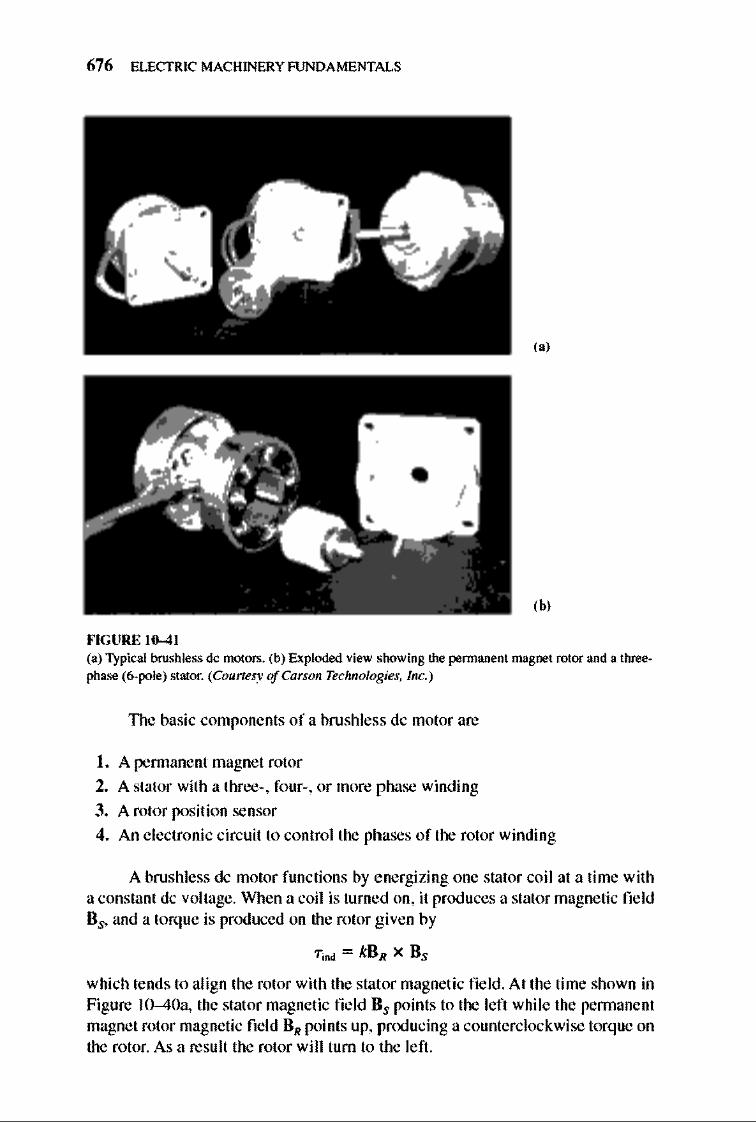
""GURE 10-41 (a) Typical brushless dc motors. (b) Exploded view showing the permanent magnet rotor and a threephase (6-pole) stator. (Counesy of Carson Technologies. Inc.)
TIle basic components of a brushless dc motor are
I. A rennanent magnet rolor
2. A stator with a three-. four-, or more phase winding
3. A rotor position sensor
4. An e lectronic circuit 10 control the phases of the rotor winding
A brushless dc motor functions by energizing one stator coil at a time with a constanl dc voltage. When a coil is turned on, it prod uces a stator magnetic field Bs, and a lorque is produced on the rotor g ive n by
which lends 10 align the rolor with the stator magnelic field. At the time shown in Figure 1O--40a, the stal or magnelic fie ld Bs points to the left whi le the pennanent magnet rotor magnetic field BR points up, prOO ucing a counterclockwise lorque on the rotor. As a resuli Ihe rotor wi ll tum to the left .

SINGLE-PHASE AND SPECIAL-PURPOSE MOTORS 677
If coil a remained energized all of the time, the rotor would turn until the two magnetic fi e lds are aligned, and the n it would stop, just like a stepper motor. The key to the operation of a brushless dc motor is that it includes a position sensor, so that the control circuit will know when the rotor is almost aligned with the stator magnetic fi e ld. At that time coil a will be turned off and coil b will be turned on, causing the rotor to again experience a counterclockwise torque, and to continue rotating. nlis process continues indefinite ly with the coils turned on in the order a, b, C, d, - a, - b, -C, - d, etc., so that the motor turns continuously.
The e lectronics of the control circuit can be used to control both the speed and direction of the motor. The net effect of this design is a motor that runs from a dc power source, with full control over both the speed and the direction of rotation.
Brushless dc motors are available only in small sizes, up to 20 Wor so, but they have many advantages in the size range over which they are avai lable. Some of the major advantages include:
I. Relatively high efficiency.
2. Long life and high re liability.
3. Little or no maintenance.
4. Very little RF noise compared to a dc motor with brushes.
5. Very high speeds are possible (greater than 50,000 r/min).
The principal disadvantage is that a brushless dc motor is more expensive than a comparable bru sh dc motor.
10.7 SUMMARY
The ac motors described in previous chapters required three-phase power to function. Since most residences and small businesses have only single-phase power sources, these motors cannot be used. A series of motors capable of running from a single-phase power source was described in this chapter.
The first motor described was the universal motor. A uni versal motor is a series dc motor adapted to run from an ac supply, and its torque-speed characteristic is similar to that of a series dc motor. The universal motor has a very high torque, but it s speed regulation is very poor.
Single-phase induction motors have no intrinsic starting torque, but once they are brought up to speed, their torque-speed characteristics are almost as good as those of three-phase motors of comparable size. Starting is accomplished by the additi on of an auxi liary winding with a current whose phase angle differs from that of the main winding or by shading portions of the stator poles.
The starting torque of a single-phase induction motor depends on the phase angle between the current in the primary winding and the current in the auxiliary winding, with maximum torque occurring when that angle reaches 90°. Since the split-phase construction provides only a small phase difference between the main and auxi liary windings, its starting torque is modest. Capacitor-start motors have
678 ELECTRIC MACHINERY RJNDAMENTALS
auxiliary windings with an approx imately 90° phase shift , so they have large starting torques . Permane nt split-capacit or motors, which have smaller capacitors, have start ing torques intennediate between those of the split-phase motor and the capacitor-start motor. Shaded-pole motors have a very small effecti ve phase shift and therefore a small starting torque .
Re luctance motors and hysteresis motors are special-purpose ac motors which can operate at synchrono us speed without the rotor field windings required by synchrono us motors and which can accelerate up to synchronous speed by the mselves. These motors can have either single- or three-phase stators.
Stepper motors are motors used to advance the position of a shaft or other mechanical device by a fi xed amount each time a control pulse is received . 1lley are used extensively in control syste ms for positioning objects.
Brushless dc motors are simil ar to s tepper motors with pennanent magnet rotors, except that they include a position sensor. 1lle position sensor is used to switch the energized stator coil whenever the rotor is almost aligned with it, keeping the rotor rotating a speed set by the control e lectronics. Brushless dc motors are more expensive than ordinary dc motors, but require low maintenance and have high reliability, long life, and low RF noise. They are available only in small sizes (20 W and down).
QUESTIONS
10- 1. What changes are necessary in a series dc motor to adapt it for operation from an ac power source?
10-2. Why is the torque-speed characteristic of a lUli versal motor on an ac source different from the torque-speed characteristic of the same motor on a dc source?
10-3. Why is a single-phase induction motor lUlable to start itself without special auxiliary windings?
10-4. How is induced torque developed in a single-phase induction motor (a) according to the double revolving-field theory and (b) according to the cross-field theory?
10-5. How does an auxiliary winding provide a starting torque for single-phase induction motors?
10-6. How is the current phase shift accomplished in the auxiliary winding of a splitphase induction motor?
10-7. How is the current phase shift accomplished in the auxiliary winding of a capacitor-start induction motor?
10-8. How does the starting torque of a pennanent split-capacitor motor compare to that of a capacitor-start motor of the same size?
10-9. How can the direction of rotation of a split-phase or capacitor-start induction mo-tor be reversed?
10-10. How is starting torque produced in a shaded-pole motor? 10-11. How does a reluctance motor start ? 10-12. How can a reluctance motor run at synchronous speed? 10-13. What mechanisms produce the starting torque in a hysteresis motor? 10-14. What mechanism produces the synchronous torque in a hysteresis motor?
SINGLE-PHASE AND SPECIAL-PURPOSE MOTORS 679
10-15. Explain the operation of a stepper motor. 10-16. What is the difference between a permanent-magnet type of stepper motor and a
reluctance-type stepper motor? 10-17. What is the optimal spacing between phases for a reluctance-type stepper motor?
Why? 10-18. What are the advantages and disadvantages of brush less de motors compared to or
dinary brush dc motors?
PROBLEMS
lO-1. A 120-V, ~hp, 60-Hz, four-pole, split-phase induction motor has the following impedances:
RI = 1.80n R2 = 2.50 n
XI = 2.40 n X2 = 2.40 n
At a slip of 0.05, the motor's rotational losses are 51 W. The rotational losses may be assumed constant over the normal operating range of the motor. If the slip is 0.05, find the following quantities for this motor: (a) Input power (b) Air-gap power (c) P coov
(d) POOl (e) "T"md
(j) "", (g) Overall motor efficiency (h) Stator power factor
10-2. Repeat Problem 10-1 for a rotor slip of 0.025. 10-3. Suppose that the motor in Problem 10-1 is started and the auxiliary winding fails
open while the rotor is accelerating through 400 r/min. How much induced torque will the motor be able to produce on its main winding alone? Assuming that the rotationallosses are still 51 W, will this motor continue accelerating or will it slow down again? Prove your answer.
10-4. Use MATLA8 to calculate and plot the torque-speed characteristic of the motor in Problem 10--1, ignoring the starting winding.
10-5. A 220-V, 1.5-hp, SO-Hz, two-pole, capacitor-start induction motor has the following main-winding impedances:
RI = 1.40n
R2 = 1.50n
Xl = 1.90n
X2 = 1.90n
At a slip of 0.05, the motor 's rotational losses are 291 W. The rotational losses may be assumed constant over the normal operating range of the motor. Find the following quantities for this motor at 5 percent slip: (a) Stator ClUTent (b) Stator power factor (c) Input power (d) PAG
(e) P coov
680 ELECTRIC MACHINERY RJNDAMENTALS
(j) P(g) Tind
(h) Tlood
(i) Efficiency
10-6. Find the induced torque in the motor in Problem 10--5 ifit is operating at 5 percent slip and its terminal voltage is (a) 190 V, (b) 208 V, (c) 230 V.
10-7. What type of motor would you select to peIform each of the following jobs? Why? (a) Vacuum cleaner (b) Refri gerator (c) Air conditioner compressor (d) Air conditioner fan (e) Variable-speed sewing machine (j) Clock (g) Electric drill
10-8. For a particular application, a three-phase stepper motor must be capable of stepping in 10° increments. How many poles must it have?
10-9. How many pulses per second must be supplied to the controllUlit of the motor in Problem 10-8 to achieve a rotational speed of 600 r/min?
10-10. Construct a table showing step size versus number of poles for three-phase and four-phase stepper motors.
REFERENCES
I. Fitzgerald. A. E. . and C. Kingsley. Jr. Electric Machinery. New Yort: McGraw-Hill. 1952. 2. National Electrical Manufacturers Association. Motors and Generators. Publication No. MG I-
1993. Washington. D.C.: NEMA. 1993. 3. Veinott. G. C. Fractional and Sulifractional Horsepov."er Electric Motors. New York: : McGraw
Hill. 1970. 4. Werninck:. E. H. (ed.). Electric Motor Handbook.. London: McGraw-Hill. 1978.