ELECTRIC LINEAR MOTION PRODUCTS
90
3600-4051E MSS Controller/Microstepping Motor Drive USER’S MANUAL TOL-O-MATIC, INC Excellence in Motion ® ELECTRIC LINEAR MOTION PRODUCTS
Transcript of ELECTRIC LINEAR MOTION PRODUCTS

3600-4051E
MSS Controller/MicrosteppingMotor Drive USER’S MANUAL
TOL-O-MATIC, INCExcellence in Motion®
ELECTRIC LINEAR MOTION PRODUCTS

B A S I C S C H E M A T I C C O N N E C T I O N — M S S
IN/JOG COM
IN/JOG COM
JOG CCW
JOG CW
IN 4
IN 3
IN 2
IN 1
FAULTÐ
FAULT+
OUT 3Ð
OUT 3+
OUT 2Ð
OUT 2+
OUT 1Ð
OUT 1+
CCWÐ
CCW+
CWÐ
CW+
A+
AÐ
B+
BÐ
L1
L2/N
GND
MRS
MOTOR
17 FRAME
MSS
YLW
RED
ORN
BLKA+
AÐ
B+
BÐ
A+
AÐ
B+
BÐBLUE
RED
YELLOW
WHT
MRS
MOTORS
23 & 34 FRAME
GRN
WHT
BLK
BLK
BRN
BLU
N.C.
BRN
BLK
BLU
BRN
BLK
BLU
+
Ð
FORM ÒCÓ REED
SWITCH
HALL EFFECT
SINKING SWITCH
HALL EFFECT
SOURCING SWITCH
NO CONNECTION FORSOURCING SWITCHES
SINKING
LOAD
SOURCING
LOAD
5-24 VDC
POWER
SUPPLY
IN
COM
COM
IN

IntroductionAbout this Manual ..................................................................................... 1
Safety Symbols........................................................................................1CW, CCW Definition ..............................................................................1
Features ....................................................................................................... 2
ConnectionsConnections & Adjustments ......................................................................3Connecting the AC Line..............................................................................4
Installing an AC Line Cord ....................................................................6Connecting the Motor ................................................................................7Computer Connection ...............................................................................8
Wiring InputsOverview ......................................................................................................9Connecting an Input to a Switch or Relay ...............................................10Connecting an NPN Proximity Sensor to an Input.................................10Connecting a PNP Proximity Sensor to an Input....................................11Jog Inputs ...................................................................................................11Limit Switches ...........................................................................................12
Wiring a Limit Switch..........................................................................13Limit Sensors .............................................................................................13
Setting for Normally Open or Normally Closed .................................15MSS Operation When a Limit Switch is Activated ..................................15
Wiring OutputsOverview ....................................................................................................16Programmable Outputs ............................................................................17Fault Output...............................................................................................17
Stop Button/Fault ProtectionFront Panel Stop Button............................................................................18Fault Protection .........................................................................................18
Tol-O-Motion MSS Programming SoftwareOverview ....................................................................................................19Installing the Programming Software......................................................19Using the Software to Input System Settings ..........................................21
Setting the Motor Current....................................................................21Idle Current Reduction ........................................................................22Setting the Microstepping Resolution.................................................22Setting the User Units ..........................................................................23Setting the Jog Parameters...................................................................24
Contents
i

Setting for Limit Switches....................................................................25Using the Tol-O-Matic MSS Software for Programming Motion...........26
Overview...............................................................................................26
Entering the Program................................................................................28Instructions & Tools .............................................................................29Download, Upload & Execute .............................................................32Copying Instructions ...........................................................................34
Setting Program Parameters from the Computer...................................35Text Boxes .............................................................................................35Scroll Bars ............................................................................................35Option Buttons.....................................................................................36Spin Buttons.........................................................................................36
PIT InterfaceOverview ....................................................................................................37Using the Optional PIT .............................................................................37
To Display a Message on the PIT .........................................................38To Pause Until User Presses Enter .......................................................39To Let User Make a Decision (PIT Branching)....................................40To Ask the User for a Move Distance ...................................................40To Get a Speed from the User...............................................................41To Get a Repeat Count from the User..................................................42To Create a PIT Menu...........................................................................43
Programming ToolsOverview ....................................................................................................44Programming Tools ...................................................................................44
Insert New Step ....................................................................................44Delete Step............................................................................................44None .....................................................................................................44Cancel ..................................................................................................45Comment..............................................................................................45Clear ..................................................................................................45Copying Instructions ...........................................................................46
Programming InstructionsOverview ....................................................................................................47Programming Instructions .......................................................................47
PIT Prompt...........................................................................................47Feed to Length ......................................................................................49Feed & Return.......................................................................................51Feed to Sensor.......................................................................................52Feed to Sensor & Return.......................................................................53
ii
C O N T E N T S

Feed & Set Output ................................................................................54Feed to Position....................................................................................56Set ABS Position ...................................................................................57Save ABS Position ................................................................................58Seek Home ............................................................................................59Wait Time .............................................................................................61Wait Input ............................................................................................61Go To.....................................................................................................63Repeat/End Repeat...............................................................................64Reset Repeat Loop ................................................................................66Set Output ............................................................................................68If Input/Go To .......................................................................................70
Program DocumentationProgram Documentation..........................................................................74
Save/Open/Print & Quit.......................................................................74
Technical Specifications ...................................................................... 75Specifications.............................................................................................75Use & Care..................................................................................................75Dimensions................................................................................................76
MSS.......................................................................................................76PIT ........................................................................................................76
Mounting InformationMounting the MSS.....................................................................................77Mounting the Optional PIT ......................................................................77
Flush Mounting ...................................................................................78Surface Mounting ................................................................................79
Recommended MotorsMotor and Data Dimensions....................................................................80
Tol-O-Matic Catalog Motor Summary Data ......................................8017 Frame Dimensions..........................................................................8017 Frame Speed/Torque Characteristics..............................................8023 Frame Dimensions..........................................................................8123 Frame Speed/Torque Characteristics..............................................8134 Frame Dimensions..........................................................................8234 Frame Speed/Torque Characteristics..............................................82
C O N T E N T S
iii


About This Manual
This manual provides the information necessary to configure andinstall the Tol-O-Matic MSS Controller/Micro Stepping Drive for usewith any of the Tol-O-Matic MRS stepper motors.
If difficulty is encountered while configuring, installing, or program-ming the system, please contact the nearest distributor for help, orcall Tol-O-Matic at 1-800-328-2174.
This manual includes software features available with MSS units3600-0038 and software 1.40 or later. Programs developed with priorsoftware can be loaded and run on these units.
SAFETY SYMBOLS
The following symbols are used throughout this manual to alert theuser to potential safety hazards.
Caution! When this symbol appears, exercise care to avoid thepossibility of sustaining slight operator injury or equipmentdamage.
WARNING! When this symbol appears, exercise extreme cautionto avoid an IMMEDIATE DANGER of sustaining severe operatorinjury or irreparable equipment damage.
NOTE: Failure to comply with cautions, warnings and requirementsin this manual, may result in damage to equipment not coveredunder Tol-O-Matic warranties.
CW, CCW DEFINITION
For all references in this manual, clockwise or counterclockwiserotation of the motor shaft is as viewed when looking at the motormounting face with the shaft protruding toward you.
If the motor is direct-coupled to a right-hand screw actuator, CCWrotation will move the carrier toward the motor.
1
Introduction

Features
• Powerful, precise and efficient MOSFET driver providing up to5.5 amps peak per phase and microstepping to 50,800 stepsper revolution.
• Reliable, efficient, low noise 80 VDC linear, toroidal powersupply.
• Powerful, flexible, easy to use indexer.
• Separate programmable acceleration and deceleration.
• Automatic homing function.
• Connects by a simple cable to a PC for programming (cableincluded).
• Tol-O-Motion MSS Microsoft Windows®-based software forset up and programming.
• Eight inputs for interacting with the user and otherequipment.
• Four outputs for coordinating external equipment.
• Accepts 110 or 220 volt AC power (switch selectable, factorypreset for 110 volts).
• Sturdy 3 x 8 x 5.3 inch metal case with integral heat sink.Mounting brackets included.
• Pluggable screw terminal connectors for I/O, motor and acpower (all mating connectors included).
• Three LEDs indicating power, drive and indexer status.
• Drive overcurrent (short circuit) and drive over temperatureprotection.
• Optional Panel-mount Interface (PIT) allows operator toenter distances, speeds, loop counts and more
• UL and CE Recognized
I N T R O D U C T I O N
2
POWER
TEMP
SHORT
B–B+A–A+
MOTOR
N
G
L
AC P
OWER
PC/M
MI
LIM
ITS
STOP
IN 1IN 2IN 3IN 4JOG CWJOG CCWIN/JOG COMIN/JOG COM
CW+CW-CCW+CCW-OUT 1+OUT 1-OUT 2+OUT 2-OUT 3+OUT 3-FAULT+FAULT-
90V pk
MSSMicroSteppingController /Motor Drive
TOL-O-MATIC, INC.
Hamel, MN
Figure 1

Connections and Adjustments
Refer to Figure 2 for important connection and adjustment points.All mating connectors are included.
Figure 2 - CONNECTION AND ADJUSTMENT POINTS
POWER
TEMP
SHORT
B–B+A–A+
MOTOR
N
G
L
AC P
OWER
PC/M
MI
LIM
ITS
STOP
IN 1IN 2IN 3IN 4JOG CWJOG CCWIN/JOG COMIN/JOG COM
CW+CW-CCW+CCW-OUT 1+OUT 1-OUT 2+OUT 2-OUT 3+OUT 3-FAULT+FAULT-
90V pk
MSSMicroSteppingController /Motor Drive
TOL-O-MATIC, INC.
Hamel, MN
3
Connections
Inputs Connector4 Programmable
JOG CWJOG CCW
Outputs Connector3 Programmable
Fault
Stop Button
Limit Switch ConnectorCWCCW
LEDsPOWER/FAULTOVER TEMP FAULTOVER CURRENT FAULT
RS232 Connector
ConnectorMOTOR
ConnectorAC POWER
Internal SelectorSwitch 110/220 VAC

Connecting the Ac Line
110 VoltsThe MSS is set for 110 volt operation at the factory. Before directwiring the MSS to ac power, consult a qualified electrician andobserve all building and electrical codes. Follow the instructions“Installing an ac line cord”.
WARNING! Ac power can be dangerous. Use extreme caution wheninstalling the ac cord.
220 VoltsThe MSS is set for 110 Volt operation at the factory. In order to use220 Volts, a switch setting must be changed inside the case and thecorrect fuse must be installed.
1. Remove all mating connectors from the drive.2. Set the drive on its side, with the aluminum heat sink fins up.3. With a medium-sized Phillips screwdriver, remove the eight screws
at the perimeter of the case and the three screws that connect theheat sink to the internal heat bar, keeping track of which screws gowhere. See Figure 3.
Figure 3 - CASE SCREWS
NOTE: Do not remove the 1/4-20 Allen head screw that connects theheat sink to the internal transformer.
C O N N E C T I O N S
4
2 Screws(shortest length)
2 Screws 3 Screws on top(longest length)
2 Screws
2 Screws (medium length)

4. Separate the heat sink assembly from the cover and note how thewires are routed to the PC board. There are labels on the PC board toassist you.
5. Disconnect the two sets of wires connecting the heat sink/transformer assembly to the chassic/PC board. The 110/220 VacSWITCH is located on the PC board, near the ac power connector.See Figure 4.
Figure 4 - INPUT VOLTAGE SWITCH
6. Remove the 110 Vac fuse and install the 220 Vac fuse that came withyour drive. There is a label inside the drive that gives the correct fusevalues.
7. Place the voltage selector switch in the correct position according tothe labels on the printed circuit board near the switch. See theFigure 4.
8. Re-assemble the chassic/PC board assembly to the heat sink/transformer assembly by following steps 4 & 5 in reverse. Again, payclose attention to the correct orientation of the two sets of wiresconnecting these assemblies.
9. Install and tighten the screws removed in step 3. Use the correctlength screw according to the hole location.
CN1
C23
F1
CN3
110V
220V
CN1
C23
F1
CN3
110V
220V
110/220 VACSWITCH
FUSE
PC BOARD
AC POWERCONNECTOR
5
C O N N E C T I O N S

INSTALLING AN AC LINE CORD
WARNING! Always use a three-wire power cord when working withac power. Failure to do so could result in damage to the MSS and/orpersonal injury or death.
WARNING! Always disconnect the line cord from the source beforeattaching it to the MSS.
Thread the cord through the insulating rubber boot provided.Remove approximately 5 mm ( 3/16 inches) of insulation from each ofthe three wires of the line cord. Depending on its source, the powercord may have black, white and green wires or brown/blue/green.
ConnectionsRefer to Figure 5.
Figure 5 - AC LINE CORD INSTALLATION
1. Connect the black or brown wire to the MSS “L” (line or “hot”terminal of the ac power connector.
2. Connect the white or blue wire to neutral. That’s the “N” terminal.3. Finally, and most importantly, connect the green wire to the GND
terminal. This connects the MSS metal enclosure and dc powersupply ground to earth ground.
4. Follow code-approved practices if a switch or relay is to be includedin the power line cord.
C O N N E C T I O N S
6

Connecting the Motor
Caution! To avoid personal injury and/or damage to the MSS:• Never connect the motor to the driver when the ac power is on.• Never disconnect the motor while the ac power is on.• Never connect motor leads to ground or to a power supply.
Tol-O-Matic MRS stepper motors are all four-lead, parallelconnected. Four-lead motors should be connected as shown inFigure 6. See page 68 for Tol-O-Matic recommended motors.
Figure 6 - MOTOR CONNECTION
To reverse the rotation at the motor (rather than in programming),reverse the + and - connections of one phase.
Figure 7 - STEP TABLE
Step A+ A- B+ B-0 + – + –1 + – – +2 – + – +3 – + + –4 + – + –
DIR=1cw
DIR=0ccw
(Step 2 is the Power Up State)
(Full Stepping)
A+
A–
B+ B–
Black
Orange
Red Yellow
MRS 23 AND 34 FRAME MOTORS
4-leadmotor
A+
A–
B+ B–
White
Yellow
Red Blue
MRS 17 FRAME MOTOR
4-leadmotor
7
C O N N E C T I O N S

Computer Connection
To Connect to the Computer for Programming:
1. Locate the MSS within 6 feet of the computer.
2. The MSS was shipped with a black adapter plug. It has a telephone-style jack at one end and a larger 9-pin connector at the other. Plugthe large end into the computer’s (COM1) serial port. Secure theadapter with the screws on the sides. If the COM1 port is alreadyallocated, use of the COM2 port will be suggested. On somecomputers, COM2 will have a 25-pin connector that does not fitthe black adapter plug. If this is the case and COM2 must be used,a 25-to-9 pin serial adapter will be required.
3. The MSS was also shipped with a 7-foot telephone line cord. Plugone end into the adapter just attached to the computer, and theother end into the RS232 jack on the MSS.
Caution! Never connect the MSS to a telephone circuit. The MSSuses the same connectors and cords as telephones and modems, butthe voltages are not compatible.
4. When the software is loaded, it looks for COM port 1. If COM port 1is already allocated, the software will prompt to allow trying theother ports.
If the port is not already in use, the programming software will use itto communicate with the MSS, and will display the COM port usedby the MSS.
Figure 8 - COM PORT
C O N N E C T I O N S
8

Overview
Figure 9 - INPUT CIRCUIT SCHEMATIC
Caution! The maximum voltage that can be applied to an inputterminal is 24 Vdc.
The MSS input circuits can be used with sourcing or sinking signals,5 to 24 Volts. This allows connection to TTL circuits, PLCs, replaysand mechanical switches. Because the input circuits are isolated,they require a source of power. If connecting to a TTL circuit or to aPLC, power should be available from the PLC or TTL power supply. Ifusing relays or mechanical switches, a separate power supply mustbe used.
NOTE: If current is flowing into or out of an MSS input, the logicstate of that input is low. If no current is flowing, or the input is notconnected, the logic state is high.
The diagrams onthe following pages show how to connect MSSinputs to various devices.
inside MSS
COM
IN1
IN2
IN3
IN4
JOG CW
JOG CWW
2200 Ω
2200 Ω
2200 Ω
2200 Ω
2200 Ω
2200 Ω
2200 Ω
COM
9
Wiring Inputs

Connecting an Input to a Switch or Relay
When connecting an input to a switch or relay, use a normally openmomentary contact switch to trigger the MSS using a WAIT INPUTinstruction. A single throw switch may be used for parameterselection using an IF INPUT instruction. A normally openmomentary switch can be used for jogging. This connection isappropriate for Tol-O-Matic Reed Switches.
Figure 10 - INPUT SWITCH CONNECTION
Connecting an NPN-Type Proximity or Hall Effect Sensor to an Input
When the proximity sensor or Hall Effect sensor activates (closes),the input will go active (“low”). This connection is appropriate forTol-O-Matic Hall Effect Sinking Switches.
Figure 11 - NEW “SINKING” HALL EFFECT CONNECTION
MSS
BRNBLK
BLU
2200 Ω
5-24Vdc
Power
+
–
SinkingHall
Effect
IN/JOG COM
IN
MSS
GND(v-)2200 Ω
+
–IN/JOG COM
IN
5-24Vdc
Power
W I R I N G I N P U T S
10

Connecting PNP-Type Proximity or Hall Effect Sensors to an Input
When the proximity sensor or Hall Effect sensor activates (closes),the input will be “low” (active). This connection is appropriate forTol-O-Matic Sourcing Switches.
Figure 12 - PNP “SOURCING” HALL EFFECT CONNECTION
Jog Inputs
Two of the MSS input terminals are provided for jogging the motorfrom a jog switch or switches. The inputs are labeled “JOG CW” and“JOG CCW”. Activating one of the inputs commands the drive tomove the motor at a pre-designated speed until the contact isopened. A relay or mechanical switch can be used to activate the joginputs. 5-24 volt circuitry can be used. The schematic diagram of theinput circuit is shown below.
If a switch or relay is to be used, wire one end to the JOG input andthe other to the power supply negative (-) terminal. Then connectthe COM input to the power supply positive (+) terminal.
Figure 13 - JOG INPUT SCHEMATIC
inside Si5580
2200 Ω
2200 Ω
COM
JOG CW
JOG CCW
5-24Vdc
SUPPLY
+
–
MSS
BLUBLK
BRN
2200 Ω
5-24Vdc
Power
–
+
SourcingHall
Effect
IN/JOG COM
IN
11
W I R I N G I N P U T S

Jog CCW will drive the carrier toward the motor for a right-handscrew actuator with a direct coupled motor.
If the MSS is connected to a PC with the programming softwarerunning, the jog inputs will function under two conditions:
1. If the program is not executing2. If the program is executing a WAIT INPUT command.
If the MSS is operating in stand alone mode (i.e. without a computerattached) then the jog inputs work when the program is executingthe Wait Input instruction, or when waiting for a PIT (InterfaceTerminal) input. All other program execution modes inhibit thejog inputs.
Limit Switches
The MSS has two limit switch inputs, LIMIT CW and LIMIT CCW. Byconnecting switches or sensors that are triggered by the motion ofthe motor or load, the operating range of the MSS is limited. This isuseful if a program error could cause damage to the system byexceeding the mechanical operating range.
The limit inputs are optically isolated. This allows a choice of voltagefor the limit circuits of 5 to 24 Vdc. It also allows the use of long wireson limit sensors that may be far from the MSS with less risk ofintroducing noise to the MSS. The schematic diagram of the limitinput circuit is shown in Figure 14.
Figure 14 - LIMIT INPUT CIRCUIT
MSSController
Chip
2200 Ω
10K
+5V +5V
3
4
1
2
CW LIMIT+CW LIMIT–
CCW LIMIT+CCW LIMIT–
inside MSS
W I R I N G I N P U T S
12

WIRING A LIMIT SWITCH
Normally open or normally closed limit switches may be used.Either is wired as shown in Figure 15.
Figure 15 - FORM “C” LIMIT SWITCH SCHEMATIC
Limit Sensors
Some systems use active limit sensors that produce a voltage outputrather than a switch or relay closure. These devices must be wireddifferently from switches.
If the sensor has an open collector output or a sinking output, wire itas shown in Figure 16.
Figure 16 - NPN OR “SINKING” HALL EFFECT CONNECTION
MSS
BLKBRN
BLU
2200 Ω
SinkingHall
Effect
5-24Vdc
Power
+
–
CW/CCW COM
CW/CCW LIMIT
MSS
BLUBRNBLK
Form "C"
2200 Ω
+
–CW/CCW COM
CW/CCW LIMIT
5-24Vdc
Power
13
W I R I N G I N P U T S

If the sensor output goes low (current flows) at the limit, select theoption “Closed.” If the output is open, (or high voltage), choose“Open” (no current flows).
Other sensors have sourcing outputs. That means that current canflow out of the sensor output, but not into it. In that case, wire thesensor as shown in Figure 17.
Figure 17 - PNP “SOURCING” HALL EFFECT CONNECTION
If the sensor output goes high (current flows) at the limit, choose theprogram option “Closed.” If the output is low (open) at the limit,select “Open.”
Caution! The current through the MSS limit switch inputs must notexceed 20 mA. Do not use voltages higher than 24 Vdc.
MSS
BLUBLK
BRN
2200 Ω
5-24Vdc
Power
–
+
SourcingHall
Effect
CW/CCW COM
CW/CCW LIMIT
W I R I N G I N P U T S
14

SETTING FOR NORMALLY OPEN, NORMALLY CLOSED
The main window of the MSS programming software (see page 28)contains a panel for selecting the type of limit switches or sensorsbeing used (see Figure 18).
If the limit switch closes when reached, select the option buttonmarked “Closed.” This is often referred to as a normally open switch.If the limit switches are closed when the motor is not at a limit, andwill open when reached, select the option button “Open.” This typeof switch is frequently called normally closed.
Figure 18 - LIMIT SWITCH SELECTION PANEL
If limit switches are not required (caution: beware of potential foractuator damage) choose “not used”. With this selection, the limitswitch inputs may be used as programmable inputs.
MSS Operation When a Limit Switch is Activated.
If a limit is reached during a FEED TO LENGTH, FEED TO SENSOR,FEED & RETURN or FEED TO SENSOR & RETURN move, the MSSwill immediately stop the motor (with no deceleration) and turn offthe motor current. The red POWER LED on the front panels will flash,and no future motion is possible. Ac power must be removed from thedrive to reset this condition. If the drive is connected to a computer,the programming software will alert the user to this condition. Resetcan be from the computer (instead of removing ac power).
If a limit is reached while jogging (using the JOG CW or JOG CCWinputs), motion will be disabled in the direction of travel. Jog can beactivated in the reverse direction to back away from the limit.
During a SEEK HOME instruction, the motor will reverse directionwhen a limit is encountered, and continue seeking the home sensor.
15
W I R I N G I N P U T S

Overview
The MSS provides three programmable ouputs (OUT 1, 2, 3) and aFault output.
All four outputs are optically isolated, meaning there is no electricalconnection between the indexer-drive and the output terminals.The signal is transmitted to the output circuit as light. This signaldrives a transistor (NPN type) that closes, or conducts current, whenthe output is low. When the output is high, the transistor is open.
Figure 19 - OUTPUT CIRCUIT SCHEMATIC
Caution! The maximum permissable voltage between any pair of + and - output terminals is 24 Vdc. Never connect ac voltages to the MSS output terminals. Maximum current is 100 mA per output.
330Ω+5V
OUT1–
OUT1+
MSSController Chip
inside MSSOUT 1+OUT 1-OUT 2+OUT 2-OUT 3+OUT 3-
FAULT+FAULT-
Wiring Outputs
16

Programmable Outputs
IMPORTANT NOTE: At power-up, the MSS sets all three program-mable outputs high (open circuit).
Since there is no electrical connection to the MSS, current andvoltage must be sourced from a PLC (programmable logic controller)or from a separate power supply. The current must be limited to lessthan 100 mA so that the output transistor is not damaged. A resistoris normally used for this, but some loads (such as PLC inputs) limitthe current automatically.
Figure 20 shows how to connect an MSS output to an optically-isolated PLC input.
Figure 20 - CONNECTING AN MSS OUTPUT TO AN ISOLATED PLC INPUT
Fault Output
The fault output should be connected using the sameconsiderations as the Programmable outputs.
PLCCOMMON
INPUT
MSS#1
OUTPUT-
OUTPUT+
12-24 Vdc Power Supply
+ –OUT 1+OUT 1-OUT 2+OUT 2-OUT 3+OUT 3-
FAULT+FAULT-
17
W I R I N G O U T P U T S

Front Panel STOP Button
There is a button marked “STOP” on the front panel of the MSS. Thisbutton can be used to interrupt motion at any time. After pressingthe STOP button, the motor will stop. No motor current will flow andthe motor will not provide holding torque. The front panel POWERLED will then flash until the MSS is reset by removing and restoringthe power. If the MSS is connected to a computer running the Tol-O-Motion MSS Software, the software will alert the user on screen tothe condition, and provide the option to reset the drive from thecomputer.
Fault Protection
The MSS provides protection against motor short circuits andexcessive drive temperature.
If the OVERTEMP light is on, the MSS has detected a thermalproblem and has shut down the amplifiers. The first thing to do isunplug the drive from the power source. Next, touch the heat sinkwith the fingers. If it is very hot, the drive has probably overheated.This usually means more air flow is needed around the drive.
If the SHORT (overcurrent) light is on the MSS has detected a shortcircuit and has shut down the amplifiers. Unplug the drive from thepower source. Check the motor wiring carefully. Make sure that theconnections to the drive are secure and that any unused motor leadsare insulated from the drive and power supply and from each other.Check the motor leads for shorts between phases or to ground.
Each Fault condition drives the fault output (Figure 20) to an “on”condition. The fault output is not activated by the limit switchcircuits.
Reset requires removal of ac power unless the MSS is connected tothe computer which allows software reset.
STOP Button, Fault Protection
18

Overview
The MSS is designed to be both configured and programmedthrough software. There is only the STOP button on the front paneland there are no jumpers inside. Virtually all the MSS’s functions arecontrolled by software. The Tol-O-Motion MSS programmingsoftware that comes with the drive provides for setting the motorcurrent, the step resolution, jogging parameters and limit switchpolarity. It also allows the writing of complex motion control andmachine interaction programs.
Installing the Programming Software
The MSS comes with two 3.5" software diskettes containing thesoftware used in programming. This software requires a computerconfigured as follows:
• IBM compatible 386, 486, or higher CPU• Microsoft Windows 3.1, Windows 95, 98 or NT• At least 8 MB memory (16 MB will make the software run much
faster)• 4 MB available hard drive space• VGA monitor, or better (16 bit color setting recommended)• Mouse or other input device• 3.5" floppy disk drive• A 9-pin serial port
Like most Windows-based programs, installing the MSS software ishighly automated.
To Install the Software:1. Put Disk 1 in the 3.5" drive.2. From the Windows Program Manager, select RUN from the FILE
menu. (In Windows 95, 98 and NT 4.0, choose RUN from the STARTmenu.)
3. If the 3.5" drive is drive A, enter the command line “A:\SETUP”. If the3.5" drive is B, type “B:\SETUP.”
4. The SETUP program will provide screen prompts needed to finishthe installation.
19
Tol-O-Motion MSS Programming Software

If errors are encountered during installation, it is usually due to lackof memory or conflicts with other programs already running on thecomputer. If an error occurs while installing the programmingsoftware, quit all other Windows applications and try again. Holdingdown the ALT key and repeatedly pressing TAB will show all theprograms currently running on the computer.
NOTE: Laptop computers generally present the biggest challenge toinstallation as they often come preloaded with programs that auto-matically execute on startup such as Microsoft Office and batterymanagers. Furthermore, laptops usually have the least memory.
The programming software will install more easily and run muchfaster with more memory. Eight megabytes of RAM on a Windows3.1 system is recommended (16 megabytes with Windows 95).
IMPORTANT NOTE: Several example programs are installed withthe programming software. It’s a good idea to load some of theexamples and look at them; they may help with the plannedapplication.
Upon successful installation of the software, an icon is created inWindows. Double-click this icon to initiate the software. The MAINPROGRAMMING WINDOW will appear as in Figure 28, page 28.
Programming Note: Always apply power to the MSC after theprogramming software is running on the computer.
M S S P R O G R A M M I N G S O F T W A R E
20

Using the Software to Input System Settings
SETTING THE MOTOR CURRENT
The drive current of the MSS must be set to match the motor. First,determine the rated current for the motor. Current settings for Tol-O-Matic MRS motors are shown in Figure 21. Motors can beoperated at less than the rated current, but they will have less torque than at the rated current. However, they will also run coolerand make less audible noise.
In the Tol-O-Motion MSS programming software, the current iscontrolled in the main window (Figure 28) by the panel on the upperleft side of the screen (see Figure 22). To adjust the current setting,just slide the scroll bar left or right. Precise adjustments can be madeby clicking on the arrows at each end of the scroll bar.
Figure 22 - CURRENT CONTROL PANEL
NOTE: The MSS current setting is for peak amps/phase. Othermanufacturers’ 4-lead parallel-connected motors can be used.Multiply the rms or dc Amps/phase current rating by 1.414 to findthe value for setting the MSS. For other motors, consult the factory.
21
M S S P R O G R A M M I N G S O F T W A R E
MAX. PERMISSABLE DRIVECURRENT SETTING
MOTOR AMPS (PEAK)
MRS171 1.4
MRS231 2.20
MRS232 3.60
MRS341 5.50
MRS342 5.50
MRS343 5.50
Figure 21 -TOL-O-MATIC CATALOG MOTOR CURRENT SETTINGS

IDLE CURRENT REDUCTION
The MSS is equipped with a feature that automatically reduces themotor current any time the motor is not moving. This reduces motorand drive heating. For example, setting the IDLE CURRENT to 50%reduces drive heating by about 50% and lowers motor heating by75%. This feature can be set at any of four levels: 0%, 25%, 50% and100%. The 100% setting is useful when a high holding torque isrequired, as the drive does not reduce the current at all. The 0%setting is for applications in which no holding torque is required.
Use of this feature is highly recommend. The IDLE CURRENT settingis chosen using the OPTION buttons in the MOTOR CURRENT PANEL.
SETTING THE MICROSTEPPING RESOLUTION
Most non-microstep step motor drives offer a choice between full-step and half-step resolutions. In full-step mode, both motor phasesare used all the time. Half-stepping divides each step into two smallersteps by alternating between both phases ON and one phase ON.
Microstepping drives like the MSS precisely control the amount ofcurrent in each phase at each step position as a means ofelectronically subdividing the steps even further. The MSS offers achoice of 13 step resolutions, starting at 2000 steps per revolution.The highest setting divides each full step into 254 microsteps,providing 50,800 steps per revolution when using a 1.8° motor. The default resolution is 20,000 steps/revolution.
In addition to providing precise positioning and smooth motion,microstep drives can be used for motion conversion betweendifferent units. The 25,400 STEPS/REV setting is provided for ease ofconverting motion from metric to English. (There are 25.4 mm perinch.) Another setting provides step angles that are decimal degrees(36,000 STEPS/REV makes the motor take 0.01° steps.) Some settingsare used with lead screws. When the drive is set to 2000 STEPS/REVand used with a 5 pitch lead screw, the result is .0001 inches/step. IfUser Units are inches, then Steps/User Unit are 10,000 steps/inch.
Choose a resolution that is convenient for the User Unit scaling ratioand which gives smooth motor operation.
M S S P R O G R A M M I N G S O F T W A R E
22

If in doubt, choose 20000 STEPS/REV. The motor will run moresmoothly and quietly at 20000 steps/rev than at lowerresolutions.
The microstep resolution of the MSS is set using the program-ming software. The resolution appears at all times in theSTEPS/REVOLUTION PANEL on the left side of the MAINWINDOW (see Figure 23).
Figure 23 - STEP/REVOLUTION PANEL
To change the resolution, click on the CHANGE button to access adialog box with OPTION buttons for each resolution (see Figure21). Click the resolution required, then click the OK button.
If the step resolution is changed, the software will ask if userunits are also to be changed. If not, it will automatically scalethe distances so that the program distances in user unitsremain the same. Note that the maximum steps for a moveare 16,000,000.
SETTING THE USER UNITS
The main programming window (see Figure 28) allows selection ofUser Units. This selection is used in conjunction with the MicrostepResolution selection of steps/revolution to set a scaling factor whichallows move requirements to be entered (whether in programming orvia the PIT) in the user’s preferred units. Default steps/rev are 20,000and user units are inches with a default of 40,000 steps/inch. Thesedefaults correspond to a 2 turn per inch screw.
To make a new selection click the cursor on the Change box for UserUnits name (Figure 25) and enter a one to four digit description(mm, inch, feet, stps, revs, ????). Using the selected steps/resolutioncalculate the steps/unit (using screw pitch or belt wheel diameterand gear ratio) and enter in the user unit box.
23
M S S P R O G R A M M I N G S O F T W A R E
Figure 21 - CHANGE RESOLUTION DIALOG BOX

Figure 25 - SETTING USER UNITS
The units for the Jog Parameters will be seen to change, as will theunits for all other screens for move data entry.
User units for PIT entries and values for entered PIT move limits willbe changed automatically. Entries in the PIT display screen will notbe changed.
NOTE: All max speeds will be subject to the 50 rev/sec maximummotor rotation speed limit set within the software.The steps/ userunit must be an integral number. Decimals will be rounded up ordown to the nearest integral. Using high values for the steps perrevolution will reduce the error. For programming metric user unitswith inch lead screws, it is helpful to use 25,400 steps/ revolution forthe resolution.
SETTING THE JOG PARAMETERS
To set the JOG SPEED and JOG ACCEL/DECEL RATE, adjust the SCROLLBARS in the MAIN PROGRAMMING WINDOW (see Figure 26).
Figure 26 - SETTING JOG PARAMETERS
M S S P R O G R A M M I N G S O F T W A R E
24

Modest accel/decel rates are appropriate for jogging. Twenty-fiverev/s/s usually works well except for very high inertial loads, in whichcase choose a lower rate. The range of jog accel is 1 to 3000 rev/s/s.
The range of jog speed is .025 to 50 rev/sec. The selection willdepend on the application.
If jogging is not required in the clockwise direction, the CW JOGinput can be used as a general purpose input by checking the boxmarked “Use Jog CW as Input 5.” The same is true for the JOG CCWinput. These selections can be implemented after system set-up.
SETTING FOR LIMIT SWITCHES
The main window of the MSS programming software (see page 28)contains a panel for selecting the type of limit switches or sensorsbeing used (see Figure 18).
If the limit switch closes (conducts current) when reached, select theoption button marked “Closed.” This is often referred to as anormally open switch. If the limit switches are closed when themotor is not at a limit, and will open (no current) when reached,select the option button “Open.” This type of switch is frequentlycalled normally closed.
Figure 18 - LIMIT SWITCH SELECTION PANEL
25
M S S P R O G R A M M I N G S O F T W A R E

Using the Tol-O-Motion Software for Programming Motion
OVERVIEW
The Tol-O-Motion MSS software has a user program capacity of 100lines. In this space, multiple motion and machine control programscan be designed. Sixteen high-level commands, or instructions, areavailable for this purpose.
Seven of the instructions involve pure motion: FEED TO LENGTHand FEED & RETURN are fixed distance moves. FEED TO SENSORand FEED TO SENSOR & RETURN move relative to a sensor that iswired to one of the inputs. FEED TO POSITION moves to an absoluteposition relative to a previously set absolute reference position.FEED/SET OUTPUT allows an output to be set at any point during amove. SEEK HOME searches for a home sensor, “bouncing off” thelimits if necessary to find it.
SET ABS POSITION allows the present position to be defined as anyabsolute position, at any point in the program.
Two instructions handle timing. WAIT TIME causes the program tostop for a specified amount of time. WAIT INPUT waits for one of theinputs to reach a specified state before continuing the program.
Four instructions control program flow. GO TO causes the programto jump to a particular line. IF INPUT jumps to a line if one of theinputs meets a specified condition. Otherwise, the program goes onto the next line. REPEAT and END REPEAT set up a loop wherein thesame instructions can be repeated many times.
The SET OUTPUT instruction can be used to signal other equipmentthat a particular place in the program has been reached.
Using the PIT PROMPT instruction with the optional Panel-mountInterface (PIT), (or operator panel), the operator can enter distances,speeds and repeat loop counts on a keypad. The drive can also displaymessages for the operator, pause the program until the operatorpresses the ENTER button, or ask the user to make a decision andrespond by pressing the YES key or NO key.
M S S P R O G R A M M I N G S O F T W A R E
26

A COMMENT tool allows notes to be inserted in the program so thatit is easier to understand.
By combining the 16 instructions in different ways, a nearly infinitevariety of useful programs and motion profiles can be constructed.Planning the objectives and sequence prior to entering instructionseases the programming process.
There are actually two software programs associated with the MSS.The first is the Windows program installed on the computer from thefloppy disks. After the program is loaded, click on the Tol-O-Maticlogo to see the software version and Tol-O-Matic’s phone, fax andwebsite numbers.
A second software program resides in a chip inside the MSS. Softwarein a chip is usually called firmware. It is the MSS firmware that runsthe drive and executes the program. The drive firmware version isdisplayed near the top of the screen when the MSS is connected tothe computer and turned on (see Figure 27). Make sure that the MSSsoftware is selected in the drop box.
Figure 27 - FIRMWARE VERSION DISPLAY
27
M S S P R O G R A M M I N G S O F T W A R E

Entering The Program
To activate the MSS software, go into Windows and locate thePROGRAMMER icon. Double-click on the icon to run the software.The MAIN PROGRAMMING WINDOW will soon appear, as shown inFigure 28. If COM 1 is used by the computer, the software willprompt for use of COM 2.
Figure 28 - MAIN PROGRAMMING WINDOW
If an MSS is connected to the computer, turn it on now. Afterapplying power, the computer should beep. The VERSION box willdisplay the version number of the MSS firmware that is in the drive.Parameter setup is described on page 35.
M S S P R O G R A M M I N G S O F T W A R E
28
INSTRUCTIONS & TOOLS
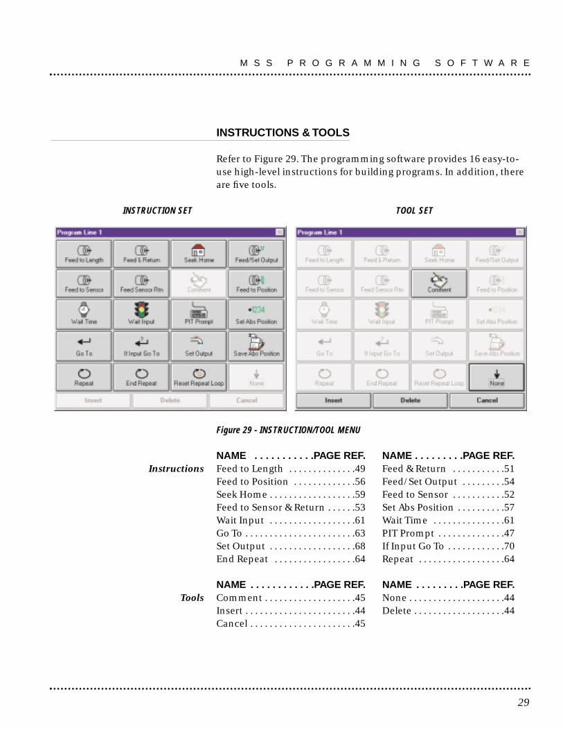
Refer to Figure 29. The programming software provides 16 easy-to-use high-level instructions for building programs. In addition, thereare five tools.
INSTRUCTION SET TOOL SET
Figure 29 - INSTRUCTION/TOOL MENU
NAME . . . . . . . . . . .PAGE REF. NAME . . . . . . . . .PAGE REF.Instructions Feed to Length . . . . . . . . . . . . . .49 Feed & Return . . . . . . . . . . .51
Feed to Position . . . . . . . . . . . . .56 Feed/Set Output . . . . . . . . .54Seek Home . . . . . . . . . . . . . . . . . .59 Feed to Sensor . . . . . . . . . . .52Feed to Sensor & Return . . . . . .53 Set Abs Position . . . . . . . . . .57Wait Input . . . . . . . . . . . . . . . . . .61 Wait Time . . . . . . . . . . . . . . .61Go To . . . . . . . . . . . . . . . . . . . . . . .63 PIT Prompt . . . . . . . . . . . . . .47Set Output . . . . . . . . . . . . . . . . . .68 If Input Go To . . . . . . . . . . . .70End Repeat . . . . . . . . . . . . . . . . .64 Repeat . . . . . . . . . . . . . . . . . .64
NAME . . . . . . . . . . . .PAGE REF. NAME . . . . . . . . .PAGE REF.Tools Comment . . . . . . . . . . . . . . . . . . .45 None . . . . . . . . . . . . . . . . . . . .44
Insert . . . . . . . . . . . . . . . . . . . . . . .44 Delete . . . . . . . . . . . . . . . . . . .44Cancel . . . . . . . . . . . . . . . . . . . . . .45
29
M S S P R O G R A M M I N G S O F T W A R E

Most programs will begin with the instruction WAIT INPUT or a PITPROMPT. This ensures that when power is applied to the MSS, itdoesn’t do anything until instructed to do so. It is easy to put a WAITINPUT instruction on the first line.
Next to the large number 1 in the PROGRAM WINDOW is a buttonshowing the NONE icon which indicates there is no instruction forthat line. Whenever the MSS encounters a “None” program line, itsimply moves on to the next line, as the icon implies with a down-ward pointing arrow. After the MSS executes the instruction on line100, it automatically jumps to line 1, unless the instruction on line100 makes it jump somewhere else.
To enter PROGRAM LINE 1, click once on the PROGRAM icon. ThePROGRAM LINE... dialog box will appear (see Figure 30), displayingthe programming instructions and tools.
Figure 30 - “PROGRAM LINE” DIALOG BOX
Click on the button marked “Wait Input”. The WAIT INPUT dialogbox will appear. Click on the option button marked “Low” (in the“Condition” group), then click OK.
M S S P R O G R A M M I N G S O F T W A R E
30

The first line of the program should now display the WAIT INPUTicon, and the description “Wait for input 1 low.”
Click on the icon button for PROGRAM LINE 2. When the PROGRAMLINE... dialog box appears, click on FEED TO LENGTH. In the FEEDTO LENGTH dialog box, enter the distance as “5 inch,” then slide thespeed bar to “10 in/sec.” Click OK.
The second program line should now show the motor icon and thecaption “CW 5.0 inch, 10.0 inch/s.”
Click on the PROGRAM LINE 3 and repeat the same steps onPROGRAM LINE 2. Only change directions to CCW. The third programline should now show the motor icon and the caption CCW 5.0 inch,10.0 inch/s.
Click on the PROGRAM LINE 4 icon. Choose GO TO. When the GOTO dialog appears, the line number will already be set to “1.” ClickOK. The program should now look like the program shown in Figure 31.
Figure 31
More complex programs are entered in the same manner, with morelines and more concern about the exact parameters and theirimportance in the application.
NOTE: To copy a line to a different program line, drag the programline, to be copied, to the program line it is to be copied to. Forexample: drag line 2 to line 3 and edit to change to CCW.
NOTE: To edit an instruction that is already in the program, holddown the shift key while clicking on the instruction icon. This is ashortcut to the instruction dialog box.
31
M S S P R O G R A M M I N G S O F T W A R E

DOWNLOAD, UPLOAD & EXECUTE
The MSS is designed to operate without a host computer once theprogram is finished and tested. However, running it from thecomputer makes it easy to quickly make changes in the program tofix errors or conduct experiments.
The programming software provides four command buttons for inter-acting with the indexer-drive: DOWNLOAD, UPLOAD, EXECUTE,and STOP.
DOWNLOAD - transfers the program from the Windows software tothe MSS plugged into the serial port. The transfer takes about 3seconds. The program must be downloaded before it can beexecuted. NOTE: If the EXECUTE button is pressed beforedownloading, the program previously loaded in the indexer-drivewill execute and the results may not match what is shown on thecomputer screen.
Set the current to match the motor’s rated current. Then, press theDOWNLOAD button near the middle of the screen. If the drive is onand connected properly, the DOWNLOAD dialog box will appear andshow the progress of the download, which takes 1-3 seconds. (Thetransfer time is governed by the speed at which the MSS can rewriteits internal, nonvolatile memory, and by the size of the program.)Once the download has been completed, the program is ready toexecute.
UPLOAD - allows extraction of whatever program is in the MSSmemory and display it on the screen. To modify a program alreadyin the MSS but never saved to the hard drive, use the UPLOADcommand to bring it back from the MSS.
EXECUTE - tells the MSS to begin running the program currently inits internal memory, starting on line 1. After pressing the EXECUTEbutton, a box Figure 32 will appear with options for the mode ofexecution, and status indicators for inputs and outputs.
If your MSS has firmware prior to 1.40, the Execute box will besimpler than this and some commands will not be available. If theprogram to be executed contains any PIT instructions (see page 37)then a different Execute box with a PIT emulation will appear(page 38).
M S S P R O G R A M M I N G S O F T W A R E
32

STOP - interrupts the indexer-drive at any point in the program andcloses the Execute box. This feature is useful when the drive startsdoing things not intended for it to do. NOTE: Remember that theMSS is a small computer and computers do not do what the operatorwants them to do, they do what the operator tells them to do.
If a motor and 2 turn per inch actuator is connected to the drive, theprogram can be tested. A normally-open-type momentary contactswitch is required. Connect one end of the switch to INPUT 1.Connect the other end to any of the GND terminals.
Jog to the motor end of the actuator. Press the EXECUTE button. TheEXECUTE dialog box will appear (see Figure 32).
Figure 32 - EXECUTE DIALOG BOX
RUN - The RUN button is lighted green (ready) and the active line ofprogram is highlighted.
Each time the switch is closed the motor should move 5 inch andreturn. (If the switch remains closed, the program will continuallyrepeat.)
I/O STATUS - The execute box displays the status of the I/O duringprogram execution.
33
M S S P R O G R A M M I N G S O F T W A R E

PAUSE - The PAUSE button halts the program but does not close theExecute box. While paused the display of inputs is continuouslyupdated in response to the source status.
STEP - When in Pause, clicking on Step will execute the highlightedprogram line, then automatically pause again. Clicking on Run willmake the program run again from where paused.
RESET - Clicking Reset sends the program back to line 1 in eitherPause or Run mode.
The MSS will run its stored program immediately on application ofpower when not connected to a computer with MSC ProgrammerSoftware open. Starting the program with a WAIT PROMPT or a PITPROMPT will prevent unintended moves.
COPYING INSTRUCTIONS
There may be occassions where it would be useful to make an exactcopy of an instruction, or perhaps a copy with only one or twoparameter changes. The fastest way to copy an instruction from oneline to another is to point the mouse at an instruction icon that is tobe copied and drag the icon onto another one elsewhere in theprogram. This is referred to as “Drag and Drop.”
For example, if there is a SET OUTPUT instruction on line 5 of yourprogram, and an identical SET OUTPUT is required on line 11.Position the mouse over the SET OUTPUT icon on line 5, then clickand hold the mouse button. Move the mouse until the icon is overthe line 11 icon. let go of the button, and the instruction with all ofits parameters will be copied to line 11.
M S S P R O G R A M M I N G S O F T W A R E
34

Setting Program Parameters From the Computer
The Windows-based programming makes it easy to enter data intothe program.
TEXT BOXES
Large numbers that must be entered precisely, such as the numberof steps to move, are entered in text boxes. This is much like using aword processor, but only one word is being edited. Just click in thebox and type in the number. If a mistake is made, select all or part ofthe number and type something else instead. When a dialog boxcontaining text boxes is first encountered, the text inside one box isautomatically selected. This allows typing in the number withouthaving to click at all.
If a number is entered that is too large, the MSS Programmer willchange the entry so that it is “in bounds” when it moves to the nextentry in the dialog box. This prevents asking the indexer-drive to dosomething beyond its capabilities.
SCROLL BARS
Many parameters are set using scroll bars. Scroll bars work like thetemperature controls in many cars. Sliding the small box to the rightincreases the value of the parameter. Sliding the box all the way tothe right provides the maximum number. As the slider moves, thenumerical value is shown in a box next to the scroll bar.
Refer to Figure 33. To make precise adjustments, try clicking next tothe slider (on the bar, between the sliding box and the arrow). Tomake even more precise adjustments, click on the arrow at eitherend of the scroll bar.
35
M S S P R O G R A M M I N G S O F T W A R E

Figure 33 - PRECISE SCROLL BAR ADJUSTMENT
OPTION BUTTONS
Option buttons are very common in Windows. They are normallyused to pick one item from a group, such as CW or CCW direction.To pick an item that is controlled by option buttons, click on thecircle so it shows a black dot inside as shown in Figure 34.
Figure 34 - OPTION BUTTON
SPIN BUTTONS
Some parameters have a limited number of possible values, allnumerical, but too many for option buttons. For example, there are100 possible values in setting the line number in a GO TO instruction.For each, use the spin button. If the down arrow part of the button isclicked (see Figure 35), the value goes down by one. Clicking the uparrow makes it go up by one. Clicking and holding down the mousebutton will cause the parameter value to “spin up” quickly.
Figure 35 - SPIN BUTTON
Click here for small change.
Slide for large change.
Click here for smallest change.
M S S P R O G R A M M I N G S O F T W A R E
36

Overview
The MSS is available with an optional Panel-mount Interface (PIT),sometimes called an operator panel. The optional PIT INTERFACEcan be used to change parameters such as MOVE DISTANCES, MOVESPEED or REPEAT COUNT NUMBER.
Using the Optional PIT
The PIT attaches to the same RS232 port used to connect to thecomputer, using the same cable. The PIT has a four-line liquid crystaldisplay (LCD) and 20 keys for entering data. There are eight primaryfunctions of the PIT:
1. Display a message on the LCD. Examples: Identify the machine(“ABC Bottle Filling Co. Model 20”), or display a status message(“Machine Running - Status OK”).
2. Pause the program until the user presses ENTER. Example: Halt theprocess of applying preprinted labels while a new roll of labels isloaded.
3. Prompt the user to make a decision. Example: Offer the user anoption such as changing set up parameters, that can be respondedto by pressing the YES or NO keys.
4. Prompt the user to enter a move distance. Example: Specify howlong the material will be when used in a machine that feeds outmaterial and then cuts it off.
5. Prompt the user for a move speed. Example: Adjust a feed rate, flowrate or other motor speed related setting.
6. Prompt the user for a repeat count. Example: The user sets thenumber of parts that are processed or combines a repeat loop with aWAIT TIME instruction to adjust dwell time.
7. Multiply branching using keys 1-8. Offer the user a choice ofjumping to eight different sub-routines, within the overall program.
8. Perform jogging. Use the left and right arrow keys for jogging whilein waiting for ENTER.
37
PIT Interface

To run a program (which includes PIT instructions) from thecomputer, press the EXECUTE button. The PIT EXECUTE dialog boxlooks and acts like the real PIT (see Figure 36). It will displaymessages, and clicking on the buttons will enter data. The PITemulator EXECUTE box has all the display, run and step functionsof the basic EXECUTE box (page 33).
Figure 36 - ON-SCREEN PIT EMULATION
TO DISPLAY A MESSAGE ON THE PIT (see Figure 37)
1. Click on the program line arrow icon.2. Select the PIT PROMPT instruction.3. Type a message (“Machine Running Status OK”) in the text box.4. Select the DISPLAY TEXT ONLY option button.5. Click the OK button. The message will stay on the LCD until another
instruction uses the PIT.
Figure 37 - DISPLAYING A MESSAGE ON PIT
P I T I N T E R F A C E
38
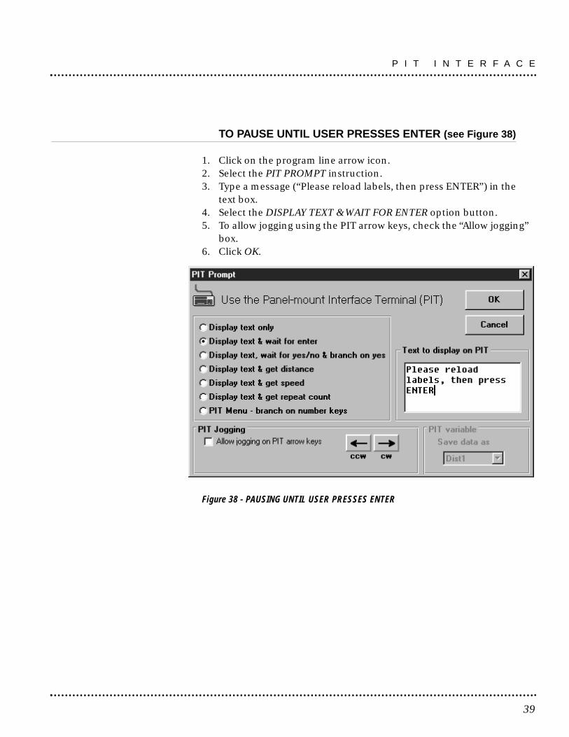
TO PAUSE UNTIL USER PRESSES ENTER (see Figure 38)
1. Click on the program line arrow icon.2. Select the PIT PROMPT instruction.3. Type a message (“Please reload labels, then press ENTER”) in the
text box.4. Select the DISPLAY TEXT & WAIT FOR ENTER option button.5. To allow jogging using the PIT arrow keys, check the “Allow jogging”
box.6. Click OK.
Figure 38 - PAUSING UNTIL USER PRESSES ENTER
39
P I T I N T E R F A C E

TO LET USER MAKE A DECISION (PIT BRANCHING) (see Figure 39)
1. Select the PIT PROMPT instruction for the program line.2. Type a message (“Change setup parameters? (press yes or no)”) in
the text box.3. Select the option button DISPLAY TEXT, WAIT FOR YES/NO &
BRANCH ON YES.4. Type the Program Line # (“12”) to go to on YES in the line # box.5. Click OK.6. Enter program or comment(s) (parameter setting instructions),
starting on Program Line # (“12”).7. If required, place a GO TO LINE # instruction at the end of the
parameter-setting instructions.
Figure 39 - PIT BRANCHING
TO ASK THE USER FOR A MOVE DISTANCE (see Figure 40)
1. Select the PIT PROMPT instruction for the program line.2. Type a message (“Enter part length, in inches”) in the text box.3. Select the option button DISPLAY TEXT AND GET DISTANCE.4. Enter upper and lower limits (this example allows the operator to
enter distances between 0.5 and 12 inches).5. Select a PIT variable to store the distance in (choose Dist1 this time,
but any of the eight PIT variables is acceptable for storing any typeof data).
6. Later in the program, provide a feed instruction (FEED TO LENGTH,FEED & RETURN, etc.) that uses the Dist1 variable for distance.
P I T I N T E R F A C E
40

Figure 40 - PROMPT USER FOR MOVE DISTANCE
TO GET A SPEED FROM THE USER (see Figure 41)
1. Select the PIT PROMPT instruction for the program line.2. Type a message (“Enter the speed, in mm/sec”) in the text box.3. Select the option button DISPLAY TEXT AND GET SPEED.4. Enter upper and lower limits (this example allows the operator to
enter speeds between 0.5 and 50 mm/sec).5. Select an PIT variable in which to store the speed (choose Speed1).6. Later in the program, provide a feed instruction (FEED TO LENGTH,
FEED & RETURN, etc.) that uses the Speed1 variable for speed.
Figure 41 - PROMPT USER FOR SPEED
41
P I T I N T E R F A C E
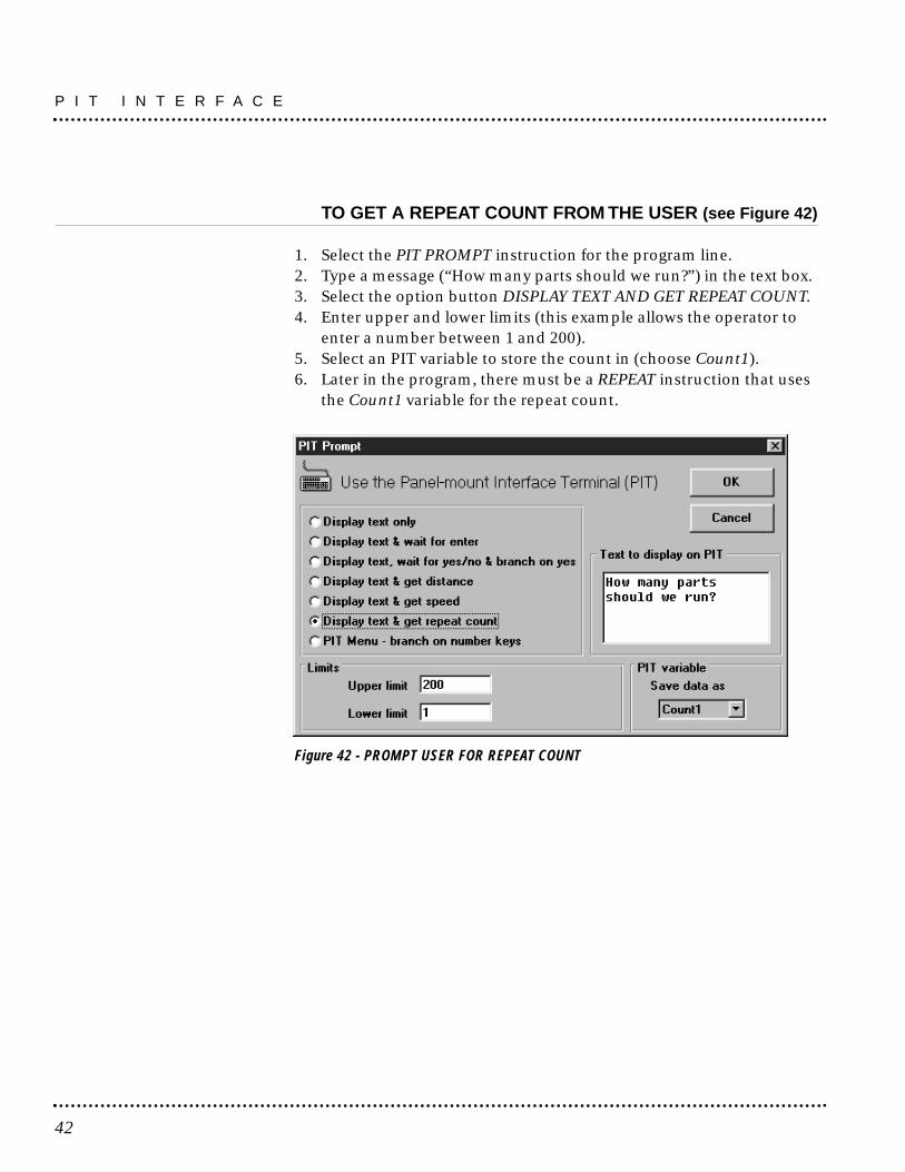
TO GET A REPEAT COUNT FROM THE USER (see Figure 42)
1. Select the PIT PROMPT instruction for the program line.2. Type a message (“How many parts should we run?”) in the text box.3. Select the option button DISPLAY TEXT AND GET REPEAT COUNT.4. Enter upper and lower limits (this example allows the operator to
enter a number between 1 and 200).5. Select an PIT variable to store the count in (choose Count1).6. Later in the program, there must be a REPEAT instruction that uses
the Count1 variable for the repeat count.
Figure 42 - PROMPT USER FOR REPEAT COUNT
P I T I N T E R F A C E
42

TO CREATE A PIT MENU (see Figure 43)
Figure 43 - PROMPT USER FOR SUBROUTINE SELECTION
1. Select the PIT PROMPT instruction for the program line.2. Select the option button “PIT Menu…”3. Type a message in the text box.4. Check the boxes indicating which numeral keys are to be used (in
this example, 1, 2, 3 and 4).5. Assign a program line number to each key (10, 20, 30 and 40).6. Later in your program, there must be instructions at each of the
lines you’ve specified. These are the instructions that will execute ifthe user presses the appropriate key on the MMI. For example, whenthe user presses ‘1’, the program will branch to line 10.
NOTE: If you add extra spaces to your display text to get the look“just right”, watch out: sometimes the MSS Programmer removesthose spaces when you re-open the instruction dialog. It is safer toformat your text using other characters, like ‘.’ (period) or ‘_’(underscore).
NOTE: You need firmware version 1.41 or later to execute the PITMenu function.
43
P I T I N T E R F A C E

OverviewThese are five programming tools which appear in the Program Linedialog box (page 27). In addition the CLEAR button of at the top right ofthe main programming window provides an additional tool function.
Programming Tools
INSERT NEW STEP
This command is used to insert a new instruction anywhere in theprogram.
To insert a new step:1. Click on the program icon where the new instruction is to go. The
PROGRAM LINE... dialog box will appear.2. Click on the command button marked “Insert”. The instructions are
re-ordered, and the line needed for the new program line isavailable.
3. Click on the OPEN line and select an instruction.
DELETE STEP
In addition to inserting a line in the program, deletions can be madeto make room for other lines farther down. For example, space existsin the middle of the program, but additional instruction is needednear the end.
To delete a step:1. Click on a program line that is not needed. The PROGRAM LINE...
dialog box will appear.2. Click on DELETE to remove the selected line and move the other
lines up one position. A blank spot will be created at the end of theprogram.
NOTE: By combining insertions and deletions, program lines can beplaced wherever and whenever needed.
NONE
This tool on the PROGRAM LINE dialog box leaves a blank programline for future use without the need to Insert later.
Programming Tools
44

CANCEL
This tool exits from programming without saving or downloadingthe program.
COMMENT
This tool provides for insertion of notes into the program. Commentshelp organize the program and make future changes easier.
Whether the program is saved to disk or downloaded to the drive,comments stay with it. They do not affect the way the program runs.When the MSS executes a program, it simply skips over the comments.
Refer to Figure 44. Placing a comment on the first line of theprogram lets future programmers know who wrote the program,when it was written, and what it does. Adding comments to theprogram may save a great deal more time later on, when programsteps are no longer obvious.
Figure 44 - COMMENT DIALOG BOX
There is a limit to the number of comments the program can have.The MSS has a string pool of 400 characters. All PIT PROMPTS textgoes into the string pool, as any COMMENT, WAIT INPUT orIF INPUT instructions whose strings exceed 12 characters.
CLEAR
Clicking on the CLEAR button at the top right of the programmingscreen and then confirming OK will erase all the program stored anddisplayed in the active main programming window Lines 1-100.CLEAR does not clear the program stored in a connected MSS.
45
P R O G R A M M I N G T O O L S

COPYING INSTRUCTIONS
The fastest way to make an exact copy of an instruction or perhapsa copy with small changes is to point the mouse at the instructionicon to be copied, click and hold and drag the icon to the copylocation. Release the mouse button. This is “Drag and Drop”.
P R O G R A M M I N G T O O L S
46

Overview
There are 16 Programming Instructions which appear in the PROGRAMLINE dialog box. Each icon, (except End Repeat) accesses anindividual dialog box in which the instruction is fully defined.
Programming Instructions
PIT PROMPT
The PIT PROMPT instruction is used with the optional PIT (ManMachine Interface). PIT PROMPTs allow the program to displaymessages on the PIT screen, and can gather data from the operatorto be used by other instructions (see Figure 45). The PIT can alsopause the program until the user presses the ENTER button. It canallow the user to make a decision, then press the YES or NO button. Ifthe user presses YES, the program branches to another program line.If the user presses NO, the program goes to the next line. If authorizedthe PIT can be used as a jog switch, while waiting for enter.
Figure 45 - PIT PROMPT DIALOG BOX
47
Programming Instructions

To display a message (such as “Machine Running - Status OK”), putan PIT PROMPT instruction in the program at the point where themessage is to appear. Check the option button marked “Display TextOnly” and type in the message. Once the PIT PROMPT instructionhas been executed, the message will stay on the screen untilchanged by another instruction that uses the PIT display.
If it is required that the operator be able to change parameters likeDISTANCE, SPEED or REPEAT COUNT, an PIT PROMPT is requiredto ask the user for data and to store it in nonvolatile memory. In thiscase, click on the option button for the type of required: DISTANCE,SPEED or REPEAT COUNT.
Upper and lower limits must be set. The PIT PROMPT instructionwill check the data entered against the limits specified and tell theuser if a value is out of range. For example, if the PIT PROMPT is setto gather a REPEAT COUNT, and the upper and lower limits are setto 100 and 1, the operator will not be able to enter any value biggerthan 100 or smaller than 1. The PIT will not accept limits greaterthan the MSS can allow.
The PIT PROMPT instruction must be told where to store the data innonvolatile memory. There are eight locations to choose from. Theyare named DIST1, DIST2, DIST3, SPEED1, SPEED2, COUNT1,COUNT2 and COUNT3. Remember where the PIT PROMPT wasinstructed to put the data. When an instruction is set up to use datafrom an PIT variable, that instruction must be told which variable touse (DIST1, DIST2, etc.). Any location can be used for any variable(i.e. distances could be put in speed or count locations).
For example, if the operator is to be able to set the number of partsthe machine produces in a given run, put an PIT PROMPTinstruction in the program to ask for a REPEAT COUNT and to save itas COUNT1. Set up a REPEAT loop somewhere else in the program toprocess the parts. The loop will start with a REPEAT instructionconfigured to get its repeat count from the PIT variable COUNT1.
If a PIT PROMPT instruction is to get distance or speed data, UserUnits will be as selected on the Main Programming window.
P R O G R A M M I N G I N S T R U C T I O N S
48

To pause the program until the user presses the ENTER key on thePIT, choose the option marked “Display text & wait for enter.”
To allow the user to make a decision, select DISPLAY TEXT, wait for"Yes/No & branch on yes.” Be sure to enter a line number in theLINE # BOX. The program will jump to that line if the user pressesYES. If the user presses NO, the program will execute the next lineafter the PIT PROMPT.
FEED TO LENGTH
This instruction is used for point-to-point incremental moves.This is the instruction to use to move the motor a fixed number ofuser units. Speed or distance data previously gathered by an PITPROMPT instruction can also be used.
Clicking on the FEED TO LENGTH button in the PROGRAM LINE...dialog box causes the FEED TO LENGTH dialog box appear (seeFigure 46). This is where the parameters for the move are entered.
Figure 46 - FEED TO LENGTH DIALOG BOX
49
P R O G R A M M I N G I N S T R U C T I O N S

DISTANCE - the number of user units to move. (The maximumnumber of steps is 16,000,000.) Selecting the check box marked “Getdistance from PIT” allows a choice of one of the eight PIT variablesas the distance. NOTE: Checking “Get distance from PIT” does notautomatically make the MSS stop and ask the user for an entry. A PITPROMPT instruction is needed elsewhere else in the program for that.
SPEED - the maximum speed the motor is to go, in user units.(The speed can be set anywhere between .025 and 50 rev/sec, inincrements of .025 rev/sec.) Selecting the check box marked “Getspeed from PIT” allows a choice of one of the eight PIT variables asthe speed.
The Feed to Length instruction also allows for reducing speedduring the move. Check the option box and enter the requiredvalues, or choose to enter the values via the PIT.
ACCEL - step motors cannot achieve a high speed instantly. Theindexer-drive must gradually accelerate the motor to speed. Theacceleration rate depends on the inertia of the motor and load, thetorque available from the motor, and how fast it is to go. Fortrapezoidal move profiles (speed vs time), MSS accel and decel ratesare limited to 3000rev/sec/sec. (For triangular move profiles, wherethe target speed is never reached, the sume of the accel and decelrates must not exceed 4000 rev/sec/sec. Thus, the fastest profile isachieved with accel and decel at 3000 rev/sec/sec and speed at thetrapezoidal limit. This profile may not be possible in the applicationbecause of mechanical limitations.)
DECEL - this is the rate at which the drive decelerates to a stop at theend of the move. The range is the same as for acceleration. Becausefriction encourages a motor to stop, decel can often be set higherthan accel.
DIRECTION - Choose CW or CCW as the direction for the move.Simply dot the appropriate circle by clicking on it.
ANALYSIS - This button presents a speed-time and a speed-distancegraph of the move along with a calculation of the move duration andthe times and distances spent accelerating and decelerating. Peakspeed is also displayed.
P R O G R A M M I N G I N S T R U C T I O N S
50

FEED & RETURN
The FEED & RETURN instruction (Figure 47) is used for point-to-point moves with return to the starting point (e.g. a motor driving acut-off knife is to retract the knife after cutting).
Figure 47 - FEED & RETURN DIALOG BOX
FEED & RETURN requires many of the same parameters as FEED TOLENGTH: DISTANCE, SPEED, ACCEL, DECEL and DIRECTION. Forexplanations of these, see “Feed to Length” on pages 00–00.
RETURN SPEED must also be set. In the case of the cut-off knife, setto feed slowly as the knife is cutting, then retract quickly. Thus, thereturn speed would be higher than the forward speed.
RETURN DELAY determines how long the MSS waits between theend of the feed move and the start of the return. This could, forexample, give the machine time to remove a part before retracting.Since a motor and load need time to “settle out” after moving, do notset return delay to less than 0.2 seconds unless it is certain that themotor and load settle more quickly than normal.
51
P R O G R A M M I N G I N S T R U C T I O N S

FEED TO SENSOR
This instruction (Figure 48) allows the motor to move until anexternal event changes the state of an input.
One useful application for FEED TO SENSOR is when the motiondistance varies. An example of this is using a step motor to dispenselabels that come on a roll. The spacing of the labels is not exact, so itis not practical to simply feed out the same number of steps eachtime. Instead, use a sensor on the feed mechanism that “sees” theedge of each label and signals one of the MSS inputs to stop motion.
Figure 48 - FEED TO SENSOR DIALOG BOX
FEED TO SENSOR will ask for many of the same parameters as theother feed programs: SPEED, ACCEL, DECEL and DIRECTION. It isalso necessary to specify a distance since the MSS must haveenough space to decelerate to a stop once the sensor is tripped. Thehigher the speed, the longer it will take to stop. If the decel rate isincreased, the motor can stop in fewer steps. The MINIMUMDISTANCE box tells how many steps must be allowed based on thespeed and decel rate that is set. The distance cannot be set to lessthan this minimum.
The MSS must also be told which input the sensor is wired to andwhat input condition to look for. The four input conditions are:
HIGH - move until the specified input reaches a high voltage (nocurrent) state. This is the default state of an input if nothing isconnected to it.
P R O G R A M M I N G I N S T R U C T I O N S
52

LOW - move until specified input is at a low voltage (closed) state. RISING EDGE - move until the signal goes from low (currentflowing) to high (no current flowing). This is similar to the highcondition, but the difference is important. Assume a sensor is wiredto the MSS, that will go high when motion is to stop. However, thesensor signal stays high after motion is complete, going low at a latertime. This often happens in labeling applications where there isn’tmuch space on the roll between labels. By choosing high as theinput condition, the MSS will complete the motion, then refuse tostart again because the input signal is still high. If a rising edge ischosen, the MSS can be restarted with the input voltage high andstop again when the sensor signal again goes from low to high.FALLING EDGE - the opposite of rising edge. The MSS onlyrecognizes the high to low transition (no current to current flow).SAFETY DISTANCE - A safety distance and program line can beentered such that if the system does not see or reach the sensor,then, at the safety distance, motion (feed instruction) will stop andthe program will go to the referenced line.
FEED TO SENSOR & RETURN
This instruction is the same as FEED TO SENSOR, except the motorreturns to the starting point after the move.
Figure 49 - FEED TO SENSOR & RETURN DIALOG BOX
Most of the parameters are the same as FEED TO SENSOR, excepttwo new ones are added: RETURN SPEED and RETURN DELAY.
53
P R O G R A M M I N G I N S T R U C T I O N S

A useful application of FEED TO SENSOR & RETURN is a variabledistance application. If a machine cuts fabric of different sizes andthe MSS is driving the cutoff knife, it is appropriate to set a sensor atthe end of the cut off stroke. That way, manual adjustment can be forthe width of material being used on a particular day without havingto reprogram the MSS.
The indexer-drive feeds each time it is triggered until the knife tripsthe sensor, then returns to the starting point.
NOTE: The maximum distance for any program is 16,000,000 steps,the longest distance the MSS can track. If a move of more than 16million steps is made before reaching the sensor, the MSS will notreturn to the correct position. If this is a problem, consider selectinga lower microstep resolution. At 50,000 steps/rev, the 16 million steplimit is exceeded after 320 revolutions. At 2000 steps/rev, 8000 revscan be made before exceeding the limit.
FEED & SET OUTPUT
The FEED & SET OUTPUT instruction (Figures 50, 51, 52) allowscombination of a Feed to Length instruction with a Set Outputinstruction, making the program shorter. Feed to Length and SetOutput are frequently used in combination to make the MSS signalanother device when it finishes a move.
Figure 50 - MOVE PARAMETER DIALOG BOX
P R O G R A M M I N G I N S T R U C T I O N S
54

Figure 51 - OUTPUT PARAMETER DIALOG BOX
Also the Feed & Set Output feature can improve manufacturingthroughput. The MSS may be advancing a part which will then beprocessed by another device; for example feeding material to be cutoff by a blade. If the blade requires some time to approach thematerial, it helps to trigger the blade before the material is fullyadvanced. That way, more pieces in the same amount of time.
Feed & Set Output allows an output to be set high or low at any pointduring the move. The Output Parameter Dialog Box allows flexiblesetting of the output timing and condition.
The analysis display (Figure 52) shows the motion profile and thetransition of the output in either speed vs time or spread vs distanceformat.
Figure 52 - ANALYSIS DISPLAY
55
P R O G R A M M I N G I N S T R U C T I O N S

FEED TO POSITION
This instruction moves the motor and load from wherever they areto an absolute position. For example, if the load is at the 4 inchposition and the program executes a Feed to Position 6 inches, themotor will move two inches clockwise. If the load was at the 10 inchposition and a Feed to Position 6 inches was commanded, the movewould be 4 inches counter clockwise.
Feed to Position requires the usual move parameters: speed, accel &decel rates. Like other move instructions, speed can be recalled froma PIT variable, allowing it to be entered by the operator on the PITpanel.
Position can be a positive or negative number, Position can beentered on the PIT, but note that the PIT has no minus (-) key, so anegative number cannot be entered on the PIT. Avoid using negativeabsolute positions by using the Set Position instruction.
Figure 53 - FEED TO POSITION DIALOG BOX
P R O G R A M M I N G I N S T R U C T I O N S
56

SET ABS POSITION
This instruction (Figure 54) allows the present motor position tobe defined as any absolute position. The Seek Home instructionautomatically clears the absolute position counter when it’sfinished, defining the home position as 0. However, it may bepreferable to define the home sensor as the 8 inch position, or90 degrees, or whatever. Simply put a Set Position instruction afterthe Seek Home instruction, or anywhere else in your programwhere appropriate to define the absolute position.
Figure 54 - SET POSITION DIALOG BOX
If the PIT is to be used for entering Absolute Positions, choose theposition setting to allow PIT entries to be positive values.
57
P R O G R A M M I N G I N S T R U C T I O N S

SAVE ABS POSITION
This instruction (Figure 55) allows the present absolute position tobe saved to a PIT variable. This is useful if an operator is to visuallyposition the load, and then be able to return to that position later inthe program.
For a material handling application, a program could be createdusing the Wait Input command to allow the operator to move theload into position. The operator would then press an ENTER buttonto exit the Wait Input instruction. If the next instruction was SaveAbs Position, the load position that the operator carefully obtainedwould be recorded in nonvolatile memory. Elsewhere in yourprogram a Feed to Position instruction to return the load to thesaved position could be used.
The MSS supports up to 8 PIT variables, so as many as eight differentpositions can be saved.
Even though the positions that the indexer has “learned” are stillremembered after shutdown (because they are stored in nonvolatilememory), it is necessary to “home” the system each time it’s poweredup. Otherwise, the saved absolute positions don’t make any sense.
NOTE: You need MSS with firmware version 1.52 or later to use theSave Abs Position instruction.
Figure 55 - SAVE ABS POSITION DIALOG BOX
P R O G R A M M I N G I N S T R U C T I O N S
58

SEEK HOME
This instruction allows the motor to move until a home sensor isfound. The home sensor can be wired to any of the general purposeinputs.
Some applications require the motor to start from a certain positioneach time the power is turned on, but can’t guarantee where it wasleft at the last power down. The solution is to wire a sensor to one ofthe MSS inputs and place a SEEK HOME command at or near thebeginning of the program.
Figure 56 - SEEK HOME DIALOG BOX
SEEK HOME will ask for many of the same parameters as the otherfeed programs: SPEED, ACCEL, DECEL and DIRECTION. The MSSmust also be told which input the sensor is wired to and what inputcondition to look for. The four input conditions are:
HIGH - move until the specified input reaches a high voltage (nocurrent) state. This is the default state of an input if nothing isconnected to it.LOW - move until the specified input is at a low voltage (currentflowing) state. RISING EDGE - move until the signal goes from low (currentflowing) to high (no current). This is similar to the high condition,but the difference is important. With a SEEK HOME command to ahigh input and the load already on the home sensor (causing theinput to be high), the load will not move. Instead, choose “risingedge” and the MSS will move the load off and back to the homesensor.
59
P R O G R A M M I N G I N S T R U C T I O N S

FALLING EDGE - the opposite of rising edge. MSS waits for inputvoltage to go from high, to low (no current to current flowing). If theinput is already low at the start of the home instruction, it is ignored.It must go high, then go low to be recognized.
The MSS begins a SEEK HOME command by moving the motor inthe direction specified. If the home sensor is found, the motordecelerates to a stop, then backs up to the position at which it foundthe switch edge. If a limit is encountered before the home sensor isfound, the MSS reverses the direction of motion, then proceeds tothe home sensor. That way it always ends up at the sensor no matterwhich side of the home sensor the load is started on.
For more precise homing and to be sure the home position is on thesame edge of the home sensor a double home move is required, witha short move in between to go off the sensor. This allows a slowspeed move with very small decel distance for the final homing. Thefirst home instruction can be faster.
Tol-O-Matic Application Engineers can provide recommendations.
Always use a Hall Effect switch for the home sensor.
There is a box in the lower right-hand corner of the SEEK HOMEdialog box. This tells how many steps the MSS needs to decelerateto a stop. The REQUIRED CLEARANCE box tells how much distancemust be allowed between the limit sensors and any hard stop, basedon the speed and decel rate that is set. If enough clearance is notallowed, the load may crash into something as it decelerates pasta limit while seeking home.
The higher the speed, the longer it will take to stop. If the decel rateis increased, then the motor can stop in fewer steps.
P R O G R A M M I N G I N S T R U C T I O N S
60

WAIT TIME
This is the simplest instruction. Simply enter an amount of time,and the MSS will pause for that time before proceeding to the nextline in the program. The range is 0.01 to 300 seconds.
Figure 57 - WAIT TIME DIALOG BOX
The WAIT TIME instruction can be made to last longer (than 300seconds) by placing a repeat loop around it. First factor the 3 minutedelay into two parts. The most delay in one WAIT TIME instruction is300 seconds. Therefore, six times 300 seconds results in 1800seconds or 30 minutes. The program is shown in Figure 58.
Figure 58 - WAIT TIME INSTRUCTION
Loops can be nested to provide very long delays.
WAIT INPUT
Rarely does a motion controller operate completely on its own withno input from the outside world. The WAIT INPUT command is usedto cause the MSS to wait before it starts a motion.
61
P R O G R A M M I N G I N S T R U C T I O N S

Figure 59 - WAIT INPUT DIALOG BOX
The WAIT INPUT instruction has two parameters (see Figure 59).The first is to specify the input. The second parameter is what kindof voltage condition to expect. The choices are:
HIGH - Wait until the specified input is at a high voltage (no current)state. This is the state an input will be in if nothing is connected to it,so be careful using this condition. If a wire comes loose, it couldcause an undesired motion.LOW - Wait until specified input is at a low voltage (current flowing)state. This is the most popular configuration. A momentary contactswitch (normally open type) connected between an input andground creates this condition when the button is pressed.RISING EDGE - Wait until the signal goes from low (current flowing)to high (no current). This is similar to the high condition, but thedifference is important. For example: a signal into the MSS is onethat will go high when motion is to occur. However, the signalremains high after the motion is complete, going low sometimelater. Choosing high as the input
P R O G R A M M I N G I N S T R U C T I O N S
62
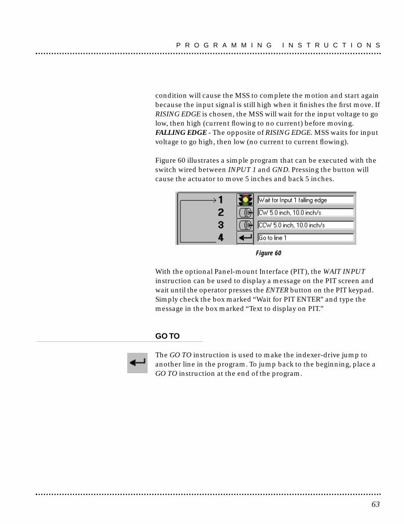
condition will cause the MSS to complete the motion and start againbecause the input signal is still high when it finishes the first move. IfRISING EDGE is chosen, the MSS will wait for the input voltage to golow, then high (current flowing to no current) before moving.FALLING EDGE - The opposite of RISING EDGE. MSS waits for inputvoltage to go high, then low (no current to current flowing).
Figure 60 illustrates a simple program that can be executed with theswitch wired between INPUT 1 and GND. Pressing the button willcause the actuator to move 5 inches and back 5 inches.
Figure 60
With the optional Panel-mount Interface (PIT), the WAIT INPUTinstruction can be used to display a message on the PIT screen andwait until the operator presses the ENTER button on the PIT keypad.Simply check the box marked “Wait for PIT ENTER” and type themessage in the box marked “Text to display on PIT.”
GO TO
The GO TO instruction is used to make the indexer-drive jump toanother line in the program. To jump back to the beginning, place aGO TO instruction at the end of the program.
63
P R O G R A M M I N G I N S T R U C T I O N S

Figure 61 - GO TO DIALOG BOX
There is only one parameter to enter in a GO TO instruction: the linenumber to jump to. Click on the SPIN button to increase or decreasethe line number.
REPEAT/END REPEAT
Sometimes the same thing is required several times. If that numberis known in advance, Repeat loops allow the instructions inside theloop to be repeated up to 65535 times.
Figure 62 - REPEAT/END REPEAT DIALOG BOX
P R O G R A M M I N G I N S T R U C T I O N S
64

Consider a system dispensing fluids into an array of containers.There are five rows and five columns of containers, each 1 inchaway from the next. Each trigger command is to cause a move tothe next position. After the fifth container is full, return to the first,4 inches back.
A MSS controlling the X axis, or motion between columns, would beprogrammed as follows:
Refer to Figure 63. The program begins on line 1, entering the repeatloop. The next four times, the MSS will wait for the voltage at Input 1to fall, then move 1 inch, taking the dispenser to the next container.After the fourth time, the MSS drops out of the loop into line 5.This time when Input 1 falls, the actuator is moved 4 inches back,returning to the original position.
Figure 63
65
P R O G R A M M I N G I N S T R U C T I O N S

Sometimes, it may be necessary to repeat something more than65,535 times. For example, material is to be fed into a cut off knifeand 100,000 pieces are to be created. The best solution is to set up 2loops, one inside the other. The total number of cycles will be thenumber of repeats in the two loops multiplied together. 100,000 is10,000 x 10, so one loop could be set for 10 and the other for 10,000as shown in Figure 64.
Figure 64
The REPEAT instruction can also use data gathered and stored by anPIT PROMPT instruction as the loop count. Check the box marked“Get repeat count from PIT” and select a variable from the list. Forexample, put an PIT PROMPT in the program to ask for the numberof parts to be processed and save that data as COUNT1. Then set upthe REPEAT instruction to get the repeat count from the PIT variableCOUNT1.
The PIT can also display the loop count. Check Display on the dialogbox and select Count up or Count down.
NOTE: If an input instruction is used to exit a Repeat Loop a ResetRepeat Loop instruction should be used to reset the loop. Otherwisethe loop resumes where it left off.
RESET REPEAT LOOP
Forces a Repeat Loop to reset its counter if it’s been terminated byan If Input or Feed to Sensor with Safety Distance instruction.
Sometimes it is necessary to leave a repeat loop before it iscompleted. If, for example, a repeat loop is set up to fill 100 bottles
P R O G R A M M I N G I N S T R U C T I O N S
66

with fluid. If the reservoir runs dry, the loop is exited by putting anIF INPUT instruction inside the loop, triggered by a fluid sensor. TheIf Input could branch outside the loop, to a PIT Prompt telling themachine operator to refill the reservoir.
Suppose that 60 bottles have been filled, with 40 remaining. For theloop to “pick up where it left off”, simply branch back to thebeginning of the loop (to the Repeat instruction) after the operatorfinishes re-filling, and the loop will automatically fill the remaining40 bottles.
On the other hand, consider a program to drill holes in parts, andeach part gets five holes. The step motor is used to advance the partby 1 inch for each hole. So, there is a repeat loop with a count of 5.Along comes a bad part, detected after the 3rd hole is drilled. Theloop is exited with 2 counts remaining.
If for the next part the program re-enters the loop again withoutreset, the next part will only get two holes drilled into it. What iswanted is for the loop to reset itself. For this, use the Reset RepeatLoop instruction as shown below.
Figure 65
67
P R O G R A M M I N G I N S T R U C T I O N S

SET OUTPUT
This command allow the choice of one of the three outputs and toput a voltage signal on it. For a detailed description of the circuitryand connections, see “Wiring Inputs" and "Wiring Outputs” sectionsof this manual.
There are four choices of output conditions (see Figure 66).
Figure 66
HIGH - Makes the photo transistor open. In circuits where the “-”output pin is grounded, and the “+” pin is pulled up, this causes ahigh voltage to appear on the “+” pin. LOW - Makes the photo transistor close. In circuits where the “-”output pin is grounded, this causes a low voltage to appear on the“+” pin.HIGH PULSE - Makes the photo transistor open for a specifiedamount of time (2 to 500 milliseconds)LOW PULSE - Makes the photo transistor close for a specifiedamount of time (2 to 500 milliseconds)
At power-up, the MSS sets all 3 programmable outputs high (opencircuit).
P R O G R A M M I N G I N S T R U C T I O N S
68

As an example of the appropriate use of the SET OUTPUT instruction,consider a system dispensing fluids into an array of containers. Eachtime the MSS moves to a new position, it should tell the dispenser ithas arrived. This can be accomplished with a high pulse, but thechoice would depend on the kind of signal the dispenser wants tosee in order to be activated.
There are five rows and five columns of containers, each 1 inch awayfrom the next. Each trigger command is to cause a move to the nextposition. After the fifth container is full, return to the first, 4 inchesback. After adding a SET OUTPUT instruction after each FEED TOLENGTH, the program is as shown in Figure 67.
Figure 67
There may be occasions when a long pulse is required. This can bedone by combining two Set Output commands with a Wait Time.The instructions shown in Figure 68 will produce a high pulse of 5seconds on Output 3.
Figure 68
69
P R O G R A M M I N G I N S T R U C T I O N S
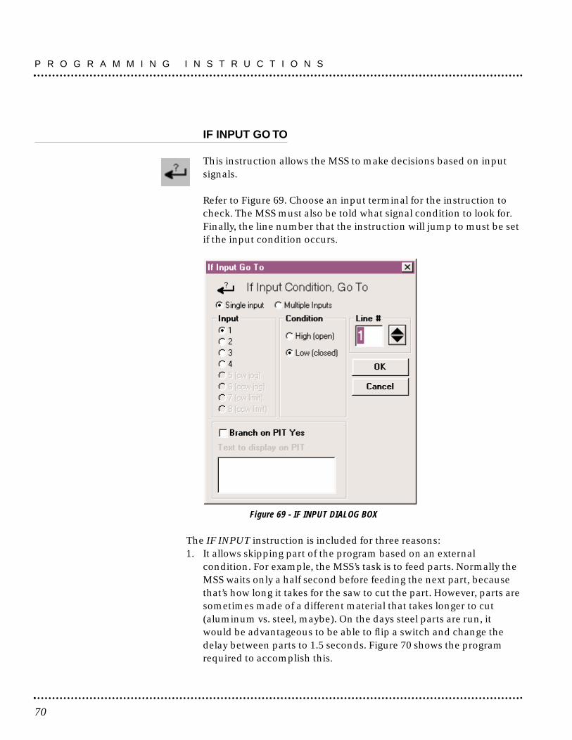
IF INPUT GO TO
This instruction allows the MSS to make decisions based on inputsignals.
Refer to Figure 69. Choose an input terminal for the instruction tocheck. The MSS must also be told what signal condition to look for.Finally, the line number that the instruction will jump to must be setif the input condition occurs.
Figure 69 - IF INPUT DIALOG BOX
The IF INPUT instruction is included for three reasons:1. It allows skipping part of the program based on an external
condition. For example, the MSS’s task is to feed parts. Normally theMSS waits only a half second before feeding the next part, becausethat’s how long it takes for the saw to cut the part. However, parts aresometimes made of a different material that takes longer to cut(aluminum vs. steel, maybe). On the days steel parts are run, itwould be advantageous to be able to flip a switch and change thedelay between parts to 1.5 seconds. Figure 70 shows the programrequired to accomplish this.
P R O G R A M M I N G I N S T R U C T I O N S
70

Figure 70
The program feeds a part during Step 4. Step 5, then makes it wait ahalf second. If the switch connected to INPUT 1 is closed (lowvoltage signal state), the program jumps to Step 8, skipping the extra1 second of delay. If the switch is open, the delay occurs. The switch’sopen circuit position can then be marked as “Steel” and the closedposition as “Aluminum.”
2. It allows a parameter to be changed such as distance or speed basedon an input. Consider the example above. How will the cut-off sawknow how fast to go when the switch is set for “Aluminum” or“Steel?” The same switch that controls the movement of the sawcould be wired to the MSS. This time, the program is written asshown in Figure 71.
Figure 71
71
P R O G R A M M I N G I N S T R U C T I O N S
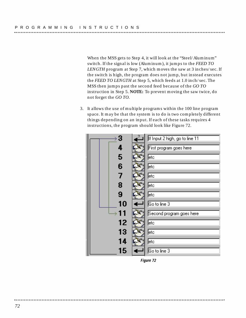
When the MSS gets to Step 4, it will look at the “Steel/Aluminum”switch. If the signal is low (Aluminum), it jumps to the FEED TOLENGTH program at Step 7, which moves the saw at 3 inches/sec. Ifthe switch is high, the program does not jump, but instead executesthe FEED TO LENGTH at Step 5, which feeds at 1.0 inch/sec. TheMSS then jumps past the second feed because of the GO TOinstruction in Step 5. NOTE: To prevent moving the saw twice, donot forget the GO TO.
3. It allows the use of multiple programs within the 100 line programspace. It may be that the system is to do is two completely differentthings depending on an input. If each of these tasks requires 4instructions, the program should look like Figure 72.
Figure 72
P R O G R A M M I N G I N S T R U C T I O N S
72

Depending on the state of Input 2, the program will either executelines 4–9 or lines 11–15. Either way, the program ultimately returnsto line 3 to check the condition of the switch again.
The optional Panel-mount Interface (PIT) can be used as thedecision making input of an IF INPUT instruction. Simply check thebox marked “Branch on PIT YES” and type in the message theoperator is to see. If the operator presses the YES button, the drivewill jump to the line specified in the line number box. If the operatorpresses NO, the program moves on to the next line.
73
P R O G R A M M I N G I N S T R U C T I O N S

Program Documentation
SAVE, LOAD, PRINT & QUIT
In addition to exchanging programs with the MSS, the programmingsoftware can also save & load programs using the hard drive, andcan print hard copies of programs using the printer.
SAVE - allows saving a program to the hard drive. A file dialog boxasks for a name for the program. Enter up to 8 characters, notincluding the suffix “.SI5”. If a suffix is not added, the software willautomatically add “.SI5” to the file name. The characters in thefilename must conform to the usual DOS/Windows 3.1 rules. Thesafest approach is to use only letters and numbers in the filename,and to avoid special characters like “?” or “\”.
OPEN - provides a dialog box showing all the “.SI5” files on the drive.Click to select one, then click OK to load it. .
PRINT - makes a hard copy of the program on any printer attachedto the computer and installed in Windows.
QUIT - exits the MSS programming software and returns to theWindows Program Manager.
Program Documentation
74

SpecificationsAmplifiers Dual, MOSFET H-bridge, 3 state, pulse width modulated switching
at 20 kHz. 0.5-5.5 peak Amps/phase output current, switchselectable in 0.2 increments. 340 watts maximum output power.Overcurrent and overtemperature protection. Automatic idlecurrent reduction (defeatable), reduces current to 50% of settingafter one second. Minimum motor inductance is 0.8 mH.
Power Supply Linear, toroidal transformer based for high reliability and low noise.110 or 220 Vac input, switch selectable (Max. ac inrush: 25 amps).50-60 Hz. 340 W max. Dc voltage at nominal line voltage: 75 Vdc fullload, 90 Vdc no load.
Inputs Optically isolated. 5-24 Vdc, 20 mA max. 2200 Ω internal resistance.Can be configured for sinking (NPN) or sourcing (PNP) signals.
Outputs Optically isolated. 12-24 Vdc, 100 mA max., per output.
Microstepping 13 switch selectable resolutions: 2000, 5000, 10000, 12800, 18000,20000, 21600, 25000, 25400, 25600, 36000, 50000, 50800 steps/rev.Waveform: pure sine.
Motion Update 12800 Hz.
Physical Constructed with black anodized aluminum heat sink and heavygauge steel housing. 3 x 5.3 x 8 inches overall. 7.8 lbs. Ambienttemperature range: 0-70 deg C. Power, over temp, and motor shortcircuit LEDs. Mounting brackets and switch cover included. Seepage 00 for detailed drawing.
Connectors European style, pluggable screw terminal blocks. Motor: 4 position(A+, A-, B+, B-). Signal Input/Output: 18 position (8 input, 6 output,4 limit). AC input: 3 position (L, N, G).
Agency Approvals CE: complies with EN55011A, EN50082-1(1996), EN50178(1997); TUV.
Fuses Wickman TR-5 style.Order from Digikey (1-800-DIGIKEY)110V: P/N WK4258BK-ND (2.5 A IEC, slow)220V: P/N WK4250BK-ND (1.25 A IEC, slow)
Maximum Case Temperature 75°C
Ambient temperature range 0 - 45°C
Use and Care• Never allow metal particles near the drive. • Never put the drive where it can get wet. • Never block the fins of the heat sink or the vent holes.• Never use the drive in a space where there is no air flow, or where
the ambient temperature exceeds 50°C.
75
Technical Specifications
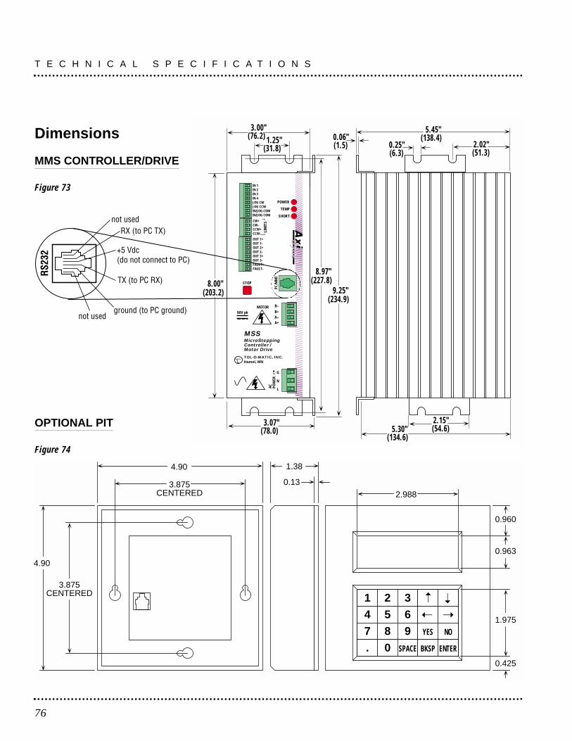
T E C H N I C A L S P E C I F I C A T I O N S
76
POWER
TEMP
SHORT
B–B+A–A+
MOTOR90V pk
G
N
LAC
POW
ERPC
/MM
I
LIM
ITS
STOP
IN 1IN 2IN 3IN 4JOG CWJOG CCWIN/JOG COMIN/JOG COM
CW+CW-CCW+CCW-
OUT 1+OUT 1-OUT 2+OUT 2-OUT 3+OUT 3-FAULT+FAULT-
3.07"(78.0) 5.30"
(134.6)
2.15"(54.6)
8.00"(203.2)
3.00"(76.2) 1.25"
(31.8)
5.45"(138.4)
2.02" (51.3)
0.25"(6.3)
0.06"(1.5)
8.97"(227.8)
9.25"(234.9)
MSSMicroSteppingController /Motor Drive
TOL-O-MATIC, INC.Hamel, MN
Dimensions
MMS CONTROLLER/DRIVE
Figure 73
4.90
4.90 1.38
0.133.875CENTERED
3.875CENTERED 1 2 3
4 5 6
7 8 9 YES NO
. 0 SPACE BKSP ENTER
2.988
1.975
0.425
0.963
0.960
OPTIONAL PIT
Figure 74

Mounting the MSS
The MSS can be mounted on the wide or the narrow side of the case.In either case, get the brackets and screws out of the accessory bagand bolt them onto the MSS. If mounting on the narrow side, firstremove one of the screws from the heat sink, then put it back withthe bracket in place, as shown in the Figure 75.
Figure 75 - MOUNTING THE MSS
Mounting the Optional PIT
There are two ways to mount the PIT in the application. In eithercase, connect the PIT to the MSS with the programming cable.NOTE: The adapter plug is not needed. The PIT has the sametelephone style connector as the MSS.
Depending on how the PIT and cable are mounted, it may bedifficult to remove the cable from the back of the PIT. If this is thecase and it is necessary to reprogram the MSS, any telephone linecord can be used as a programming cable. Be careful not to lose theadapter plug that connects the telephone cord to the COM port ofthe computer. The adapter is only available from the factory.
This screw is already inthe drive.
Bracket position for narrow side mounting. Place brackets on
top and bottom of drive.
Bracket position for wide side mounting. Place brackets on top
and bottom of drive.
77
Mounting Information
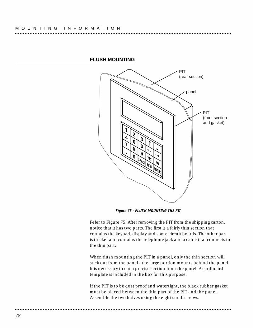
FLUSH MOUNTING
Figure 76 - FLUSH MOUNTING THE PIT
Fefer to Figure 75. After removing the PIT from the shipping carton,notice that it has two parts. The first is a fairly thin section thatcontains the keypad, display and some circuit boards. The other partis thicker and contains the telephone jack and a cable that connects tothe thin part.
When flush mounting the PIT in a panel, only the thin section willstick out from the panel - the large portion mounts behind the panel.It is necessary to cut a precise section from the panel. A cardboardtemplate is included in the box for this purpose.
If the PIT is to be dust proof and watertight, the black rubber gasketmust be placed between the thin part of the PIT and the panel.Assemble the two halves using the eight small screws.
12
3
45
6
78
9YES
NO
.0
SPACE BKSP ENTER
panel
PIT(front sectionand gasket)
PIT(rear section)
M O U N T I N G I N F O R M A T I O N
78

SURFACE MOUNTING
Figure 77 - SURFACE MOUNTING THE PIT
An easier way to mount the PIT is to bolt the two halves togetherahead of time, using the eight small screws. If the PIT is to be dustproof and watertight, put the black rubber gasket between the twohalves before screwing them together.
Next, cut a hole in the panel for the cable that runs between the PITand the MSS. The hole must be at least 5/8" in diameter for theconnector to fit through. There must be two holes that line up withthe big mounting holes in the PIT. Figure 74 shows the location ofthe big mounting holes.
When mounting the PIT to the panel, some kind of sealant will berequired to keep dust and liquid out. Silicone or latex caulking isappropriate, or make a gasket from a sheet of compliant materialsuch as rubber or RTV.
12
3
45
6
78
9YES
NO
.0
SPACE BKSP ENTER
panel
sealant (not included)
PIT
gasket(included)
79
M O U N T I N G I N F O R M A T I O N

Motor Data and Dimensions
Tol-O-Matic catalog motor current settings (Figure 78).
Tol-O-Matic 17 frame motor dimensions (Figure 79).
17 frame motor speed/torquecharacteristics (Figure 80).
MRS171
MRS231
MRS232
MRS341
MRS342
MRS343
parallel
parallel
parallel
parallel
parallel
parallel
1.4
2.20
3.60
5.50
5.50
5.50
0.17
0.66
1.39
3.21
6.56
9.66
0.66
1.5
2.5
3.2
5.3
7.6
MAX. PERMISSABLE DRIVECURRENT SETTING
AMPS (PEAK)WINDING
CONNECTIONMOTOR
ROTORINERTIA(oz-in )
WEIGHT(lbs)2
Recommended Motors
80
©.197
[5.00]
1.66
[42.16]
1.220
[30.99]
1.220
[30.99]
1.66
[42.16]
.079
[2.01]
1.69
[42.93]
.433
[11.00]
2.126
[54.00]
.787
[19.99]
.217
[5.51]
©.197
[5.00]
©.867
[22.02]3.1 In/LB
3600-6129
MRS171
White A+Yellow A-
Red B+Blue B-
Revs Per Second
To
rqu
e (o
z.-i
n.)
0
5
10
15
20
25
30
35
40
.03
.07
.10
.14
.17
.21
.24
.28
4 8 12 16 20 24 28 32 36 40
MRS231MRS171

Tol-O-Matic 23 frame motor dimensions (Figure 81).
23 frame motor speed/torque characteristics (Figure 82).
81
R E C O M M E N D E D M O T O R S
Motor LModel Max.
MRS231 2.0652.4
MRS232 3.1078.8
Black A+Orange A-
Red B+Yellow B-
6 & 5Bipolar 1 & 2parallel 8 & 7
3 & 4
200.0
180.0
160.0
140.0
120.0
100.0
80.0
60.0
40.0
20.0
0.00 4 8 12 16 20 24 28 32 36 40
Revs per Second
Torq
ue (o
z•in
)
MRS232
MRS231

Tol-O-Matic 34 frame motor dimensions (Figure 83).
34 frame motor speed/torque characteristics (Figure 84).
R E C O M M E N D E D M O T O R S
82
Motor LModel Max.
MRS341 2.5865.54
MRS342 3.7695.51
MRS343 3.7695.51
A+ BlackA- OrangeB+ RedB- Yellow
600.0
500.0
400.0
300.0
200.0
100.0
0.00 4 8 12 16 20 24 28 32 36 40
Revs per Second
Torq
ue (o
z•in
) MRS343
MRS342
MRS341

© Copyright 1999Tol-O-Matic, Incorporated. All rights reserved.Axidyne and Tol-O-Matic are registered trademarks of Tol-O-Matic Incorporated. All otherproducts or brand names are trademarks of their respective holders.
08/00 ASAP

TOL-O-MATIC, INC.3800 County Road 116Hamel, MN 55340763.478.8000 Telephone763.478.8080 Faxhttp://www.tolomatic.com