ELECTRIC FLIGHT BASICS - …nuneatonaeromodellers.org.uk/public/electutorial.pdf · Trying to skip...
25
ELECTRIC FLIGHT BASICS Introduction 1. Electric motor basics a. The three ‘golden’ motor rules b. Current limits c. Kv d. Worked example e. Caution 2. Propeller matching a. Matching propeller to motor b. Matching propeller to plane c. Examples – matching and mismatching d. Matching process - power requirement - speed requirement - diameter selection e. What is propeller pitch? 3. Non-ideal systems a. Battery b. ESC c. Battery charge d. Motor losses e. Propeller losses f. Motor stability 4. How to construct a system in two easy lessons (provided you’ve read all previous information) 5. Miscellaneous a. Motor rated power b. Commercial software c. BECS, UBECS and OPTOS d. Battery C rating e. Battery size and flight time f ESC over-current protection g Practical safety considerations Glossary Links Feedback v1.1
Transcript of ELECTRIC FLIGHT BASICS - …nuneatonaeromodellers.org.uk/public/electutorial.pdf · Trying to skip...

ELECTRIC FLIGHT BASICS
Introduction
1. Electric motor basics
a. The three ‘golden’ motor rules
b. Current limits
c. Kv
d. Worked example
e. Caution
2. Propeller matching
a. Matching propeller to motor
b. Matching propeller to plane
c. Examples – matching and mismatching
d. Matching process - power requirement
- speed requirement
- diameter selection
e. What is propeller pitch?
3. Non-ideal systems
a. Battery
b. ESC
c. Battery charge
d. Motor losses
e. Propeller losses
f. Motor stability
4. How to construct a system in two easy lessons
(provided you’ve read all previous information)
5. Miscellaneous
a. Motor rated power
b. Commercial software
c. BECS, UBECS and OPTOS
d. Battery C rating
e. Battery size and flight time
f ESC over-current protection
g Practical safety considerations
Glossary
Links
Feedback
v1.1
Introduction
Recently, both at the field and in meetings, members have commented that ‘things
electric’ seem a bit of a black art. I’m a recent convert to electric flight myself, so
perhaps snippets from my ‘learning curve’ may help others in the same position. A lot of
the following is, of course, just my opinion and should be treated as such. Any input from
other members is very welcome.
Many articles available in magazines and on websites cover electric system basics. Some
(few) also attempt to also include prop selection and matching (much more critical with
electric than i.c). Really, it’s impossible to deal with electric motors without considering
propellers so, for what it’s worth, here’s an article which attempts to do both.
As in all subjects, there are the basics and then there are the details and interactions.
Trying to skip the basics is a mistake so, initially, we’ll concentrate only on these. To the
experts, please tolerate any simplifications. Sometimes I will simply make a statement
where an explanation would otherwise clutter up the text – please just take it as read.
The article falls naturally into several ‘digestible’ portions.
- the ideal battery and motor theory
- the ideal propellers theory, including matching
- where real-life diverges from the ideal
- how to use the above information to put together a working system
- odds ‘n sods
Also included is a glossary of the electrical and mechanical terms used. To those who feel
I’m teaching granny to suck eggs, please bear with me (does anyone actually know how
to suck eggs – or why only grannies do it?).
Sometimes I’ll be talking about what to do, sometimes about what not to do, and the rest
- well, you’ll see I can waffle with the best when pushed. At times, simple maths may
best illustrate a point whilst, at others, a worked example may be better. Real numbers
always help to give a feel for what is going on. Also, many parts of the article concern
differences between i.c. and electric so comparisons will be made frequently.
In a system (i.e. battery, motor, prop and plane) the proper place to start should really be
the plane which drives the system requirements. However, as this is an article mainly
about electrics I’m going to start, particularly in part 1, at the “wrong” end with the
battery and motor. Later, when we put together a complete system, the plane comes first.
In the early sections I’ll often describe what would be observed if an ideal motor, or
propeller, were used. If you actually try this you may not measure what you expect, or the
system may behave in an unpredictable manner. Don’t worry; the ‘real-world’ factors
that also come into play are covered later.
Part 1. The Ideal Electric Motor & Battery Basics
1a) The three golden rules for dc electric motors
Let’s begin at the beginning with just a motor, speed controller (ESC) and battery,
without any propeller. Simple observation raises two interesting questions.
i) If we were to open the throttle wide, the motor would spin up but only to a specific
rpm, no faster. Why not? What’s holding it back?
ii) The battery voltage is, say 10V, and the specified motor resistance is, typically, 0.02
ohms, so why isn’t the motor now taking 500 amps (10V divided by 0.02 ohms)?
Well, the reason for both the above is that electric motors, once spinning, also behave like
dynamos and generate their own internal voltage which opposes the battery voltage, so
only the relatively small difference between these two voltages is left to actually drive the
current through the motor armature resistance.
This internal voltage is known as cemf (Counter EMF since emf is just another name for
voltage, and it counteracts, or opposes, battery voltage). In practice, the cemf and battery
voltage tend to be similar in size and the difference is usually relatively small.
Simply put : Vb - cemf = current x resistance (in armature)
In our test i) above, with no load (i.e. no prop) on the motor, the motor spins up to the
speed at which the increasing cemf (remember – it’s also a dynamo) almost reaches, or
balances, the battery voltage. The motor simply can’t go any faster. At this point only a
small current, known as Io, is drawn since only losses (friction etc.) need be overcome.
If Io = 2 amps (typically) this requires an armature voltage drop of only 0.04V (2 amps
x 0.02 ohms). The cemf, therefore, must be 9.96 volts i.e. 10V minus this 0.04V.
Now let’s double the battery voltage to 20V. The friction is still relatively small.
Remembering that the cemf is generated by the motor behaving like a dynamo, it is
obvious that the motor will have to spin about twice as fast to generate a cemf of nearly
20V rather than nearly 10V as before. This brings us to our first golden rule :
Golden Rule no. 1 Battery voltage defines no-load motor speed
No-load (i.e. maximum) motor speed is proportional to battery voltage. Remember this,
it’s very important !! There is no equivalent to this in an i.c. engine.
Making the motor work for its living
Of course, a freely spinning motor is use neither to man nor beast. To get useful work out
of it (torque x rpm) we need some torque as well as rpm, so let’s fit to the motor some
sort of load, e.g. propellers of various pitches. At zero pitch, no torque is required and the
motor spins at its maximum speed defined by our choice of battery voltage. Here, current
consumption is very low, as described previously.
As more load (pitch) is applied, the motor needs to supply extra power to turn the
propeller. An analogy with i.c. engines is appropriate here.
I.C. engine power is proportional to Rpm x Torque
Electric motor power is proportional to Volts x Amps
rpm equates current equates
to volts to torque
(rule no 1, above) (new rule, no 2)
Since golden rule 1 says that electric motor rpm and battery volts (left hand arrow above)
are directly related then it follows that motor current is similarly related to torque (right
hand arrow). This brings us nicely to our golden rule no 2 :
Golden Rule no 2 Motor torque is directly related to armature current
The more we load up our motor, the higher must be the armature current. We could say
that torque = Kt x current, where Kt has units of torque per amp. More about Kt below.
We’re nearly there, just one more characteristic to consider. What is the mechanism that
causes the motor current and, hence, torque to actually rise as propeller load increases ?
We’ve seen that armature current is related to the difference (Vb – cemf). Since battery
voltage is almost constant (well, it is here) then the only way for current to rise is to
increase the voltage difference available by reducing the cemf. Since cemf is a ‘dynamo’
voltage that is related to motor speed, so it logically follows that the motor speed must
drop to reduce the cemf, thus allowing the rise in current.
Hence : Golden rule no. 3 Armature current is related to motor speed dip
In order to increase armature current and, hence, torque the motor speed must fall, but
only by a bit. The more torque is applied, the more the speed falls. Easy peasy !
These three rules are all we need to understand the principles of electric
motor behaviour in model planes.
Time for a cup of tea !

1b) Current limits
The above three rules give us all the information we need, for now, to understand why an
electric motor behaves as it does. In practice, motors have physical limits. Let’s look at
one here – the current limit, and see how it applies to our above motor plus 10V battery.
For the time being, assume the battery voltage is a constant 10V, and we know that at
zero load the current (Io) is very small. Let’s now go to the other end of its operating
range, to the current limit of the motor (usually printed on the case). This limit is there to
prevent the motor overheating (heat = armature resistance x current2 ).
Let’s assume the current limit is 50A. To push this through our armature resistance of
0.02 ohms requires exactly 1 volt (ohms law : volts = 50 amps x 0.02 ohms). Our cemf
now needs, therefore, to be 9V (10V battery voltage minus the 1V across the armature).
Since cemf is a dynamo effect, the reduction from 9.96 to 9V represents (approximately)
a 10% reduction in rpm from no-load to get to the 50A max current. Such a speed dip is
not untypical for a model electric motor. As mentioned earlier, the speed dip is always a
relatively small fraction of the no-load speed. It is the increase in current of 48A above Io
that actually gives us useable output torque.
The ESC, of course, must also cope with the maximum motor current and, ideally, 50%
more since heat is likely to affect the ESC components more quickly than the motor..
Of course, if even more load is applied, by “over-propping” (or inserting miscellaneous
body parts into the propeller), then the speed will fall even further, and the motor current
will (quite happily) exceed its rated limit since, basically, there’s little to stop it. The ESC
might, but it’s not guaranteed. In the extreme, if the torque that is applied is sufficient to
fully stall the motor then the current WILL be huge, maybe hundreds of amps (but not
for long !!).
1c) Meet ‘Kv’, a very important motor parameter
Now’s a good point to mention a motor parameter “Kv”. All motors have this, usually
printed on the motor case, and it’s nothing to do with Kilovolts (you’ll no doubt be glad
to know). In fact, it’s quite a useful parameter :
- it relates no-load motor speed to battery volts ( its units are rpm-per-volt)
- it relates cemf to actual motor speed – the dynamo effect
- it relates armature current and torque as Kt is inversely proportional to Kv
The physical design of a particular the motor defines its Kv. In the above example, if our
Kv were 1000 rpm per volt then our no-load speed (at Vb = 10V) would be 9960 rpm,
since cemf (9.96V) is related to actual motor speed by Kv (reminder : the only reason the
no-load speed’s not exactly 10,000 rpm is the very small speed dip necessary to generate
Io). At full-load (50A) the speed would be 9000 rpm, since cemf = 9V.
Interestingly, the entire motor operating speed range at 10V is only about 1000 rpm, since
it can’t go faster than 9960 rpm as it has no net torque above this speed and if it goes
slower than 9000 rpm the armature current will be too high. Supply voltage then becomes
the prime means of speed control and it is the job of the ESC to reduce the battery
voltage efficiently. More on this later.
Only by changing internal motor details like number of windings and poles, can the Kv
can be altered. A motor with Kv of 200, with Vb = 10V would operate around 2000 rpm
– not really a practical choice for planes unless it’s a scale diesel. Kv can be very high
and a value of 4000 rpm/volt would shift the 10V speed up towards 40,000 rpm. Such
speeds are not uncommon; that’s the Ducted Fan end of the electric motor spectrum.
For the following examples let’s just stick just with our mid range value of Kv = 1000.
1d) A worked example to help illustrate the above
We’ve developed our 3 golden rules that define how the motor develops speed, torque
and, hence, power. We’ve also found how to adjust no-load speed via a combination of
battery voltage and motor Kv. Great theory, but what can we actually do with all this ?
We’ll, I mentioned at the outset that information is useful not only to tell us what to do
but, also, to help tell us what not to do. The following example illustrates this.
Assuming that our ideal system above was supplied by a manufacturer as part of a
package to go with one of his models, then it is likely he has done all the donkeywork
and has specified the motor (e.g. Kv = 1000, imax = 50A) and the battery as 10V (stick
with just this voltage for now). The motor output power is cemf x current which, at
maximum power, is 9V x 50A or 450W. So, he will also have recommended a prop
which, hopefully, absorbs this 450W at 9000 rpm. In short, he will have specified a
correctly matched working system.
And the plane probably flies very well. But, after a few sessions, the flyer begins to wish
he had a bit more power for the verticals. Hmm, maybe a doubling of power would be
nice. Double the power, surely that must mean two batteries. So he thinks about adding
another similar battery in series to achieve this. What would actually happen ?
Let’s apply our golden rules to this situation :
i) if the battery voltage is increased to 20V then rule 1 tells us the motor will try to run
at twice the speed (that’s 18000 rpm)
ii) prop torque will increase by a factor of 4 if the rpm doubles, so rule 2 tells us that
motor current must also increase by this factor, to 200A !
iii) rule 3 says the extra current alters the speed dip which, in turn, affects speed
If we continue along this track a little longer life gets a bit tedious.

- an armature current of 200A needs a voltage drop of 200A x 0.02 ohms or 4V, not 1V
- hence, since our battery voltage is 20V the cemf would need to be 16V ( = 20V- 4V)
- Kv = 1000 rpm/volt so motor speed would need to be 16000 rpm (not 18000 rpm).
- prop torque increase would then be a factor of (16000/9000)2 i.e. by 3.2, not 4
- 3.2 x torque requires 3.2 x current, from 50A to 160A, not to 200A
- to get a current of 160A require a cemf of 16.8V (i.e. 20V – 3.2V) not 16V
- so the speed is not 18000, or 16000, but 16800 rpm (so torque changes again)
..... and so on ad infinitum.
I’m sure you’re ahead of me here and have realised that we’re going round in circles,
(i.e. speed -> current -> cemf -> speed -> current ......... ) converging on, but never
quite reaching, the final speed and current. All our basic rules still apply individually,
but the calculations are complex. They can be done, but there is an easier way to
approach this as we shall discuss in part 3 (I’m sure, you’ll be glad to know).
(And, I’m sure I don’t need to say if the current were 200A, or even160A, or any other
similar value, then precise calculations are irrelevant. The ESC and/or motor would have
expired due to heat exhaustion long before you finished reading the above description).
1e) Caution - reminder of some very important points
We have mentioned the motors always have a maximum current rating. It is vital to
remember that the motor current is not limited by the motor, nor may it be limited by the
ESC, and certainly not by the battery. It is controlled only by YOU and is determined by
the propeller you decide to fit. If you fit too large a prop then the torque required will try
to be met, but only by the motor slowing more and the torque (and current) rising as it
tries to achieve a torque balance. If the current is excessive the motor or ESC will self
destruct. Remember – once the magic smoke has escaped it will not work !
It is vitally important to remember that the prop, motor, ESC and battery are, together, a
system. Changing any individual one part of a balanced system (particularly battery,
motor or propeller) is likely to upset other parts, as we’ve seen.
Part 1 summary
We’ve developed our three golden rules relating battery voltage, motor speed and
motor current, and these always apply, and seen how factor Kv links these.
It’s easy to upset a matched system by randomly changing individual components.
Predicting motor behaviour from scratch is difficult, and tedious, even using the
golden rules. Later we’ll see how to do this more easily.
That’s all for now. Wake up at the back there. Next article #2 will cover prop selection
and matching.
Part 2 Propeller matching
2a) Matching Propeller to Motor
Up to now we’ve mentioned the propeller as some sort of motor load without looking at
the type of load it presents. Since our complete system will, eventually, comprise battery,
ESC, motor plus propeller and plane we’ve got to look at the propeller as the common
link between the electrical system and the plane.
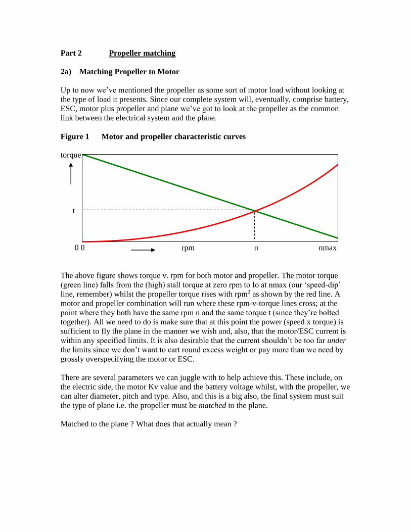
Figure 1 Motor and propeller characteristic curves
torque
t
0 0 rpm n nmax
The above figure shows torque v. rpm for both motor and propeller. The motor torque
(green line) falls from the (high) stall torque at zero rpm to Io at nmax (our ‘speed-dip’
line, remember) whilst the propeller torque rises with rpm2 as shown by the red line. A
motor and propeller combination will run where these rpm-v-torque lines cross; at the
point where they both have the same rpm n and the same torque t (since they’re bolted
together). All we need to do is make sure that at this point the power (speed x torque) is
sufficient to fly the plane in the manner we wish and, also, that the motor/ESC current is
within any specified limits. It is also desirable that the current shouldn’t be too far under
the limits since we don’t want to cart round excess weight or pay more than we need by
grossly overspecifying the motor or ESC.
There are several parameters we can juggle with to help achieve this. These include, on
the electric side, the motor Kv value and the battery voltage whilst, with the propeller, we
can alter diameter, pitch and type. Also, and this is a big also, the final system must suit
the type of plane i.e. the propeller must be matched to the plane.
Matched to the plane ? What does that actually mean ?

2b) Matching propellers to planes
Most i.c. engine flyers develop an intuitive feel for the “right” size propeller for a
particular model. Vintage and slow-flying model, pylon racers, aerobatic models and
powered gliders all have different requirements. In addition, 2 and 4-strokes, even of the
same power, tend to need different props. But why ?
Having a powerful motor (i.c. or electric) is no advantage at all unless we enable the
motor to both develop this power and to transfer it to the aircraft via the prop.
The motor develops useful power by pulling the plane through the air at a certain speed
against the drag force (since power = force x speed). A plane being held stationary on the
ground, whilst being pulled strongly, isn’t actually going anywhere. Now, or in an hour’s
time, its still just sitting there, so the motor is inputting none of its power to the plane. All
the motor power is being wasted; it’s just creating noise and stirring the air (Note : this is
not helicopter bashing)..
At the other extreme, multiplying rpm by propeller pitch gives us the theoretical speed at
which the prop would like to ‘screw’ its way through the air if nothing was holding it
back. The speed is exactly the rpm x pitch. A plane in a dive might achieve this
condition, where the airspeed is high but the thrust becomes zero. Neither the plane nor
engine would go any faster, nor slower, should the prop detach and fly off at this point.
Again, at this condition the work input to the plane from the engine is zero since,
although the speed is high, the thrust is zero.
Between these extremes of airspeed the prop is doing some useful work on the plane. The
shape of the ‘useful’ power transfer curve for a particular combination of plane, engine
and propeller is similar to the one below.
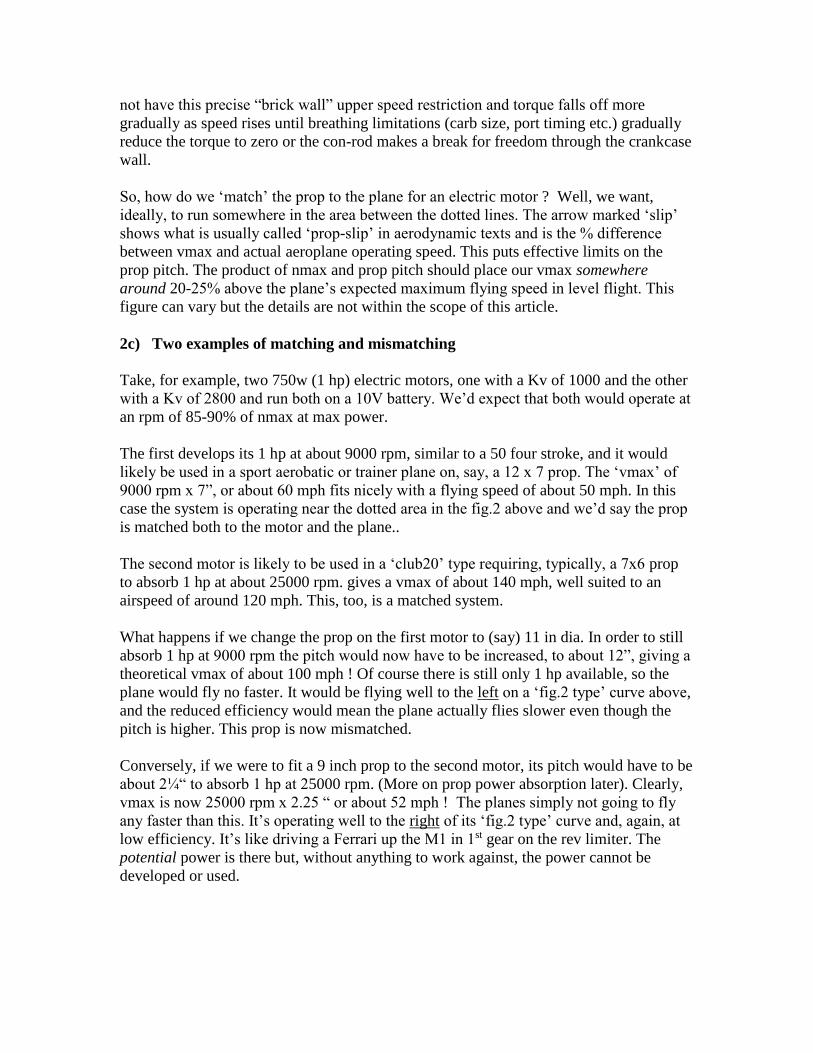
Figure 2 Propeller / plane power transfer curve (efficiency)
power slip
at rest mph vmax
Note : maximum speed ‘vmax’ is defined slightly differently for i.c. engines and electric
motors. In part 1 we saw that an electric motor will try to reach an rpm ‘nmax’ defined as
battery voltage x Kv, but no more, at which point its current and, hence, torque will be
zero. Vmax is, therefore, nmax x prop pitch for an electric motor. An i.c. engine does
not have this precise “brick wall” upper speed restriction and torque falls off more
gradually as speed rises until breathing limitations (carb size, port timing etc.) gradually
reduce the torque to zero or the con-rod makes a break for freedom through the crankcase
wall.
So, how do we ‘match’ the prop to the plane for an electric motor ? Well, we want,
ideally, to run somewhere in the area between the dotted lines. The arrow marked ‘slip’
shows what is usually called ‘prop-slip’ in aerodynamic texts and is the % difference
between vmax and actual aeroplane operating speed. This puts effective limits on the
prop pitch. The product of nmax and prop pitch should place our vmax somewhere
around 20-25% above the plane’s expected maximum flying speed in level flight. This
figure can vary but the details are not within the scope of this article.
2c) Two examples of matching and mismatching
Take, for example, two 750w (1 hp) electric motors, one with a Kv of 1000 and the other
with a Kv of 2800 and run both on a 10V battery. We’d expect that both would operate at
an rpm of 85-90% of nmax at max power.
The first develops its 1 hp at about 9000 rpm, similar to a 50 four stroke, and it would
likely be used in a sport aerobatic or trainer plane on, say, a 12 x 7 prop. The ‘vmax’ of
9000 rpm x 7”, or about 60 mph fits nicely with a flying speed of about 50 mph. In this
case the system is operating near the dotted area in the fig.2 above and we’d say the prop
is matched both to the motor and the plane..
The second motor is likely to be used in a ‘club20’ type requiring, typically, a 7x6 prop
to absorb 1 hp at about 25000 rpm. gives a vmax of about 140 mph, well suited to an
airspeed of around 120 mph. This, too, is a matched system.
What happens if we change the prop on the first motor to (say) 11 in dia. In order to still
absorb 1 hp at 9000 rpm the pitch would now have to be increased, to about 12”, giving a
theoretical vmax of about 100 mph ! Of course there is still only 1 hp available, so the
plane would fly no faster. It would be flying well to the left on a ‘fig.2 type’ curve above,
and the reduced efficiency would mean the plane actually flies slower even though the
pitch is higher. This prop is now mismatched.
Conversely, if we were to fit a 9 inch prop to the second motor, its pitch would have to be
about 2¼“ to absorb 1 hp at 25000 rpm. (More on prop power absorption later). Clearly,
vmax is now 25000 rpm x 2.25 “ or about 52 mph ! The planes simply not going to fly
any faster than this. It’s operating well to the right of its ‘fig.2 type’ curve and, again, at
low efficiency. It’s like driving a Ferrari up the M1 in 1st gear on the rev limiter. The
potential power is there but, without anything to work against, the power cannot be
developed or used.

2d) Matching process – power, speed and diameter
We’re now going to attempt to derive, from basics, the correct motor and propeller for a
particular electric model. At some points we will meet things which seem difficult, or
impossible, to specify. Later we’ll look at the ways round these problems.
This time, we’ll start at the right end – with the plane’s requirements.
i) Power To start with, the power required is related to the plane, in particular its type,
weight and required flying characteristics. How much power do we really need ?
Rules of thumb exist for this, e.g. 50 watts/lb for pottering (I warned you this was
technical), 100 watts/lb for sporty flying, 200watts/lb for “spirited” aerobatics etc.
Remember that 746w = 1 hp and use these rules of thumb together with your i.c.
experience to come up with a target power, in watts.
For example : a 60 in span 5 lb sports model (e.g. wat4) would fly well on a good 46/50
2-stroke (about 1.2 bhp) so we’re looking for around the 900w mark for a similar
‘electric’ performance. Hence, this brings us to rule #1 for planes.
Rule 1. Motor Power is defined by plane requirements (just the same as with i.c.)
ii) Flying speed The aerobatic model, above, would probably be required to fly level at
up to about 70 mph. This defines our vmax as around 85 mph. Thus, the product of
maximum motor rpm x prop pitch is defined, although we don’t know either of them at
this point.
Rule 2. Product (nmax x prop pitch) is defined by plane’s flying speed range
We have not yet separated rpm from pitch. We could elect to use a fine pitch and a high-
speed motor, or a coarse pitch with a low-speed motor. A high speed motor requires a
high battery voltage and/or a high Kv, but peak torque and current will then be low (since
power is pre-defined). Alternatively the low speed option will require a lower Kv motor
and/or lower battery voltage, and a higher current to generate the same power. The choice
is ours. How do we decide ?
iii) Decision time – ‘High nmax plus low pitch’ or ‘low nmax plus high pitch’
Well, we can, again, draw on our i.c. engine experience. Our aerobatic model would fly
on, typically, a 13x6 and we could start with this. However, prop efficiency improves a
bit with larger diameters and lower speeds. Our i.c. engine does not allow us the degree
of flexibility in max-power speed that an electric motor does. Let’s take advantage of this
flexibility and go for (say) a 15 in dia prop. Again, assume that maximum power is
developed at about 90% of nmax (10% speed dip, as in part 1).
One essential parameter we require for the next theoretical stage is the prop constant K.
Assume, for the time being, that we do know this.

Putting our data into the prop power and speed laws
max prop power = K x (0.9 x nmax)3 x dia4 x pitch = 900w (we decided this)
vmax = nmax x pitch , = 85 mph (and we decided this too)
From the above two equations we can derive both the motor nmax and prop pitch
nmax = 1/dia2 x sqrt( power / K / vmax) / 0.9
pitch = vmax / nmax (we now know nmax)
We have now theoretically determined prop pitch, diameter, motor power and the rpm at
which this has to be developed. Note that the motor speed, whatever its value, can still
be achieved using both a low voltage battery and a high Kv or vice versa. This choice
may be made on more practical considerations and will be covered later (section 3d).
Of course, at this point, we almost certainly don’t know the prop constant K, which
depends on prop design, blade section, construction, material (flexibility) etc., although
this could be derived from test stand measurements. There’s also an element of “chicken
and egg” here; how do we test a prop before we know what prop we actually need.
Neither, unfortunately, do we really know the prop pitch.
2e) What exactly is prop pitch ?
A practical problem arises when converting our required theoretical pitch into a
manufacturer’s figure and vice-versa. A flat-bottomed wing still produces lift when the
bottom of the wing is aligned with the airflow and, in fact, the wing needs several degrees
of negative incidence before it produces no lift - its aerodynamic angle of zero lift.
Likewise, unless we know whether a prop manufacturer specifies his pitch as the
geometric blade angle (that you could measure with a protractor on the rear of the blade)
or whether he bases it on the (greater) aerodynamic, or zero-lift, pitch then we still don’t
have the information we need. This, too, makes our calculations difficult.
Summary of part 2
So, why have we just gone through all the above if it can’t actually be used ?
The analysis above is shown to demonstrate that if we could define our requirements
correctly in terms of target power and speed, then there are “correct” or unique values of
matched motor rpm and prop diameter & pitch. Even though it is difficult, in practice, to
calculate these values accurately, they do, nevertheless, still exist.
It illustrates that propellers shouldn’t be selected purely at random as this is very
unlikely to produce an optimised system, particularly with electric motors

Using, or understanding, the above analysis is not important,
understanding the implications of it is !
The approach in part 4 is built around NOT having to know all the required information
(pitch or K) to reasonably match the prop and motor to the plane.
Right, cuppa tea time again.
Part 3 Non-ideal systems
In parts 1 & 2 we saw how an ideal motor, battery, ESC, prop and plane together form a
matched system subject to some “golden rules” and that, theoretically, many system
parameters can be calculated. We saw, also, that even if we cannot calculate the
parameters we require, they do exist, so random component selection is unwise whether it
be motor, battery or propeller – or all of these !
Now we’ll deal with just a few of the pesky things that cause our ideal motor, battery, etc
to not quite obey the rules in real life before moving on to actually look at developing our
system..
Why our real electrical systems are not “ideal”
Up to now, for simplicity and clarity, we’ve talked about ideal components i.e. we’ve
mainly ignored things like losses, tolerances and inefficiencies. Here are some real-world
factors which will modify (i.e. usually reduce) our ideal system performance. They do not
contradict our golden rules, they apply to just modify or adjust them.
3a) Battery internal resistance. All batteries have this. Its effect is to progressively
reduce the battery terminal voltage as current rises. This is equivalent to having near-peak
battery voltage available at low loads but a lower terminal voltage available at high loads.
A lower available terminal voltage reduces motor speed, so the overall effect is to
effectively increase the slope of our ‘speed dip’ line as load is applied.
3b) ESC internal losses The speed controller, too, has an internal voltage drop which
is related to current flowing through it, and its effect is similar to that of battery internal
resistance. Both the battery and ESC losses appear as heat in their respective component.
3c) Battery state of charge We may base all our calculations on a mean Lipo cell
voltage of 3.7V per cell but it’s worth noting that a cell terminal voltage will vary,
depending on the state of charge, from typically 3.0 and 3.7V at high load (3.0V is a
typical ESC cut-off voltage), and even up to 4.1V at light load. As a result, all our full-
load speed estimates will vary by about +/- 8% around the average, currents by about +/-
15% and powers by about +/- 20% There is no such thing as a precise battery voltage
and any value used should reflect the relevance of it. For example, you need to be more
concerned with the lowest possible voltage for minimum system performance and the
highest possible voltage for safe component specification.
Whereas up to now we’ve always talked about the motor seeing battery voltage, in
practice it sees open-circuit battery voltage (itself variable) minus internal battery voltage
drop minus ESC voltage drop and minus any voltage drop in the connecting wires
themselves. The poor old motor sees what’s left after all losses are subtracted.
3d) Motor losses Actually, we’ve effectively already included some motor electrical
losses in our calculations since driving current through the armature resistance results in
waste heat. Motors also have other losses due to bearing friction, windage (stirring the air
inside them), eddy current losses etc. (and even Kv is not that accurate, often only being
specified as within 5 or 10%).
It’s not necessary to know much in detail about electrical losses except to remember that
they are there, and always tend to result in less gain than expected (a bit like income tax
really) if you try to uprate a system. They can be minimised, but often at extra expense
(better materials, magnets, battery technology etc.). It is worth remembering that losses
tend to be much more related to current than voltage, so a system operating on twice the
volts and half the current will tend to be more efficient. Motor factor Kv is the key here
to being able to make such a decision in that low voltage goes with a high Kv and vice-
versa. But, (there’s always a ‘but’) if you elect to go the low Kv / low-current / high-
voltage route then higher voltage ESCs can be quite expensive. In general, you pays your
money and you takes your choice.
3e) Propeller losses These are difficult to quantify but are related to propeller design
and construction, and how well it is matched to the plane. Different factors affect basic
efficiency, such as blade profile, thickness, number of blades, material (stiffness) etc. and
some of these effects vary with plane speed or prop rpm. Props tend to be less efficient at
very high speeds and are particularly inefficient when the blades are stalled (just like a
wing). This can occur with a coarse pitch prop running with the plane at rest or at low
speeds (just like full-size aircraft which have variable pitch props for this reason).
Much data is available on prop design and efficiency but the average club member does
not have access to, or the facilities to make use of, this information apart from selecting
commercially available items based on recommendation or experience.
3f) Motor Stability Not a loss but more of a restriction on operating area. In real life,
the battery, motor and propeller form a complex system. In part 2, fig.1 we saw the motor
operates where the torque lines intersect. Any small speed drop (for any reason) results in
motor torque exceeding prop torque causing the motor to accelerate, resulting in prop
torque exceeding motor torque and leading to a deceleration, and so on. Similarly, a
motor speed rise increases cemf and reduces torque (current) leading, as above, to a speed
dip and, likewise, then to a speed rise and so on ....
Whether these speed fluctuations subsequently increase in size (go unstable) or die out is
well beyond the scope of this article, but avoiding instability may put a few limitations on
where you can actually operate a motor. Take heed if motor manufacturer recommends
you do not run the motor without a propeller.
Summary of part 3
So, where are we ? We’ve been presented with what seems to be an awful lot of theory,
none of which we yet appear to be recommended to use. We need component
information that we just don’t have access to, and some things vary by much more than
we’d like. We can also achieve some things in different ways. Have we really made any
progress ? Can a system ever be made to work ? Read on.

Part 4 How to be a system designer in two easy lessons
Lesson i) DON’T RE-INVENT THE WHEEL
In all areas of engineering, understanding is based not only on theory but also on
experience. Some reported experience is, of course, rubbish and some is not. And how do
you tell the difference ? Well, experience helps.
Once a technology is established, the best tends to float to the top, and this is certainly
true now of electric motors in model aircraft. Many kit or motor manufacturers, have
done all the hard work for you and recommend combinations of plane, motor, ESC,
propeller and battery. This information is easily available. Magazine reviews are often a
good source of what works well and what doesn’t. The web also contains a huge amount
of information but much may be just opinion or advertising. Be cautious.
Few modellers will (should) launch into system design without having built a couple of
such models, so they already have some experience. If you have no experience at all of
electric models the best recommendation is to get some by building an ARTF or a fully
specified kit or design.
With the increasing number of modellers involved in electric flying, there are now many
more opportunities to view models of different types flying, and to ask questions. Once
you get started with, say, an ARTF model then you quickly learn the jargon, what
questions to ask and what the answers mean.
In short, any modeller wishing to develop or alter an electric system will not be on his
own when so much information is already available. No-one should be starting from
scratch. When the time comes for some original design work, that is when none of the
available models or information suits his (or her) requirements exactly, then it shouldn’t
be too difficult to find something which is reasonably close to use as a starting point and
then use the ‘Golden Rules’ for small alterations only, as follows.
Lesson ii) FINE TUNE YOUR SELECTED SYSTEM WITH THE HELP OF
THE GOLDEN RULES
Using other people’s experience and information as a starting point, the theory in parts 1
& 2 can then be used just to make fine adjustments to component selection and can be
tested one step at a time. A lot of the apparent complications in parts 1 & 2 involved the
non-ideal interactions (mainly speed v. current v. losses). If only small adjustments are
being made then interactions become negligible and can be ignored, leaving us to treat
the components as nearly ideal. Much easier, as we shall see.
“Interactions become negligible” you hear, but compared to what ? At what point can we
stop worrying about calculation or component accuracy. Well consider this in light of all
the following.

- We have already mentioned the variability in Lipo voltage, current and power
delivery as it discharges. What voltage do you actually use in your calculations ?
- Battery, ESC and motor losses all vary between makes and types, and between
samples of the same type, and even with usage or age, in the case of batteries.
- Propeller pitch and efficiency varies with manufacturer and type, and even from
manufacturer’s published data. And what, exactly, does published pitch mean ?
- I challenge any two modellers to make the same plane from scratch and finish up
with the same weight, drag, covering (finish), rigging, alignment etc. So what target
plane, exactly, is the system intended to power ?
In short, there are many sources of inaccuracy or uncertainty involved in the
components that go together to make up a system and there comes a point where any
errors in our calculations fall well below these uncontrollable variations and can be
ignored, which we shall do. Don’t worry about them, they’re clearly not too important
else there’d be no electric models flying today.
In order to illustrate the above “real world” approach, it would help to work through an
example. This could be our modeller who wished to simply increase the performance of
his existing system by fitting a different battery.
Example : I want to go quicker as cheaply as possible
“I’m currently using 3 cells on my sport fun-jet/aerobatic/scale model and need more
speed/climb etc. Can’t I just fit a bigger battery, say 4 cells ?”
Well, let’s assume the manufacturer has done a good job and the present system is
already well-specified with respect to maximum current rating, prop matching etc. Then,
the simple answer to the above question is NO, you generally cannot “just” change the
battery on its own. (Always beware a question containing the word “just”).
Why not ? - mmm, thought you’d ask that
Our ideal motor rules tell us that increasing the battery from 3 to 4 cells will tend to
increase rpm by the same amount i.e. by a factor of 4/3 or +33%. Spinning the existing
prop this much faster will require a torque, and current, change of (4/3)2 or about +77%
requiring a power increase of (4/3)3 i.e. a factor of nearly x 2.4. We know that real-world
losses will reduce these increases, probably to around +25% in rpm, +50% torque and
maybe a doubling of power but, no matter which way we look at it, these overall changes
are considerable and, probably, catastrophic. We know that, if the system was already
correctly specified, then the increase in current of x1.5 (or anything in this region) will
almost certainly risk damage to the motor or ESC.

In order to prevent this we should ensure the maximum current does not rise. How ?
Well, in this case the only way to do this is to fit a different propeller more suited to the
higher motor rpm. So, how do we start to do this ? Well, we can start by assuming that if
we have 4/3 x the original voltage, and the same current, then we will have 4/3 x the
original power available, since power = volts x amps. What will this give us in terms of
speed ?
Aeroplane drag is proportional to mph 2 . The power required to fly a plane is
proportional to drag x mph and, hence, to mph 3 .
Hence, (new mph / old mph) 3 = 4/3 based on our power upgrade. This means that our
new mph is just 10% greater than before !! Yes, it’s true. To go faster you require lots of
power (in fact faster3 as much power, if you see what I mean). Do you still want to bother
just for 10% ? Yes, alright, let’s continue.
Our motor speed will rise roughly in line with voltage. In this case, the battery and ESC
voltage losses will not rise since we are intending to keep the current the same. So, the
motor will be going about 33% faster but the plane will be going only 10% faster so the
prop pitch will need reducing to suit (remember, we’re trying to keep as much as possible
unchanged, which means aiming at roughly the same operating point on the curve in
fig.2). What ?? More power, higher airspeed but finer pitch ? Yes, not obvious but now,
at least, we know why.
To match the 33% increase in prop rpm to the 10% increase in airspeed, our pitch will
need to be reduced by 0.83 ( = 110% / 133%). For example, if the pitch was 10 inches it
would now need to be 8.3 inches.
Next, prop torque and, thus, motor current, depends on 3 factors : prop diameter (d), pitch
(p) and prop rpm.(n).
Prop torque = K x d4 x p x n2 - general propeller law
and this must stay the same if we’re aiming to keep the current constant. Let’s call the
original prop #1 and the new one we’re trying to specify #2
So, d14 x p1 x n12 = d24 x p2 x n2 2 (for same torque and, hence, current)
Rearranging we get d2 4 = p1 x n1 2
d1 4 p2 n2 2
Since we already know that n1/n2 = 3/4 (= volts) and, also, that p2/p1 = 0.83 then
(d2/d1)4 = 0.68 so d2/d1 = 0.91 i.e. required diameter is only 91% of the original.
Let’s pause and reflect on where we’ve got to.
We started off with a matched system running on 3 cells. It consisted of a motor, ESC,
battery, and a 14 x 10 prop. We changed the battery to 4 cells, keeping the motor and
ESC the same. In order to keep the current the same as before we need to use a 12.75 x
8.3 prop which will turn 33% faster and propel the plane 10% faster.
Of course a 12.75 x 8.3 prop is a rare beast and the nearest is probably a 13 x 8. How
much too big, or small, is this ? Well, now let’s use just a little bit of our theory. The
prop law tells us that torque is proportional to (d4 x pitch) so a 13 x 8 needs 4.2% more
torque (i.e. current) than a 12.75.x 8.3 at the same rpm. The target here is to get to a
propeller size that is just a bit too big. For now this is just about perfect.
[Frankly, getting to within 4% or so is actually very good, and would probably be ok as it
is. However, let’s continue, just to demonstrate the process of fine tuning].
The motor and ESC would be unchanged, the current would, in theory, be up just a bit on
this prop and, hopefully, the new system power (volts x amps) does not exceed any
power limitation in the motor spec. (If it does, see below)
The next stage, and this is recommended for every change you make, measure and check
the static current with a wattmeter using a Lipo at least ¾ charged. All motors and ESCs
will tolerate a small degree of over-current for a short time and this is quite sufficient to
allow us check things. We believe our 13 x 8 prop will give us a current just a bit larger
than our target. Let’s check this.
The target current is, of course, the maximum current on the original components (3
cells, 14 x 10 prop) which we intend to keep the same. It may not exactly agree with the
motor spec but, for the time being, assume the supplier’s done his homework.
Then measure the current on the new setup. If our calculations are right it will be 4.2% up
on our target. Now it’s time for a dash more theory.
Trim the prop tips (slightly) to get to our target current. Remember, torque changes with
d4 so only 1.7mm off each tip of our 13 inch prop is required to reduce torque, and
current, by 4.2%. We will, therefore, finish up with a 12.87 x 8 prop where we originally
calculated we need a 12.75 x 8.3. Unless you’re a competition flyer (in which case, you’d
be unlikely to be reading this article) the pitch (= speed) difference of 3.6% is again
likely to be of no concern compared to all the other inaccuracies.
Such a degree of adjustment is perfect. Taking more off each tip of a larger prop to get to
12.87 inches could alter the effective blade outline and torque characteristics (i.e. K)
significantly, whilst just 1.7mm off a 14” prop means such undesirable secondary effects
can be ignored (i.e. they become negligible).
The maximum motor torque, and current, will remain the same, thus protecting the motor
and ESC. Contrary, perhaps, to our instincts, we’ve increased the system power but
reduced both the prop diameter and pitch. Who would have thought it ?

So, the above is just one example of how we can, by starting with a correctly specified
system, change it to suit our requirements. Other factors which can be similarly altered,
in addition to the battery voltage (above), include motor Kv & current, plane data
(weight, flying speed etc), prop diameter and pitch etc. Remember, though, these are all
part of a system and you are not advised to change just one item on its own. With a few
exceptions, the “golden rules” must be used to reoptimise the system for performance
and/or reliability.
Also, remember, this whole approach is geared to altering only those parameters we can
easily measure and adjust whilst keeping those we can’t measure or change constant. For
this reason we must try to use a prop of the same type (manufacturer, range etc) as we
were using originally to ensure K doesn’t change more than we can help. It’s also
obvious that we can adjust diameter downwards but not upwards, whereas pitch is
(effectively) not adjustable.
Do not contemplate this sort of work without a wattmeter; it’s an invaluable tool.
Part 5 Miscellaneous snippets
5a) Motor Rated Power
I briefly mentioned motor power above, and to check the rating isn’t exceeded. Motors
will often come with both a maximum power and a maximum current limit and over-
current is the main cause of motor thermal failure. Power can be increased by increasing
the battery voltage whilst keeping the current the same (as we’ve just seen). The power is
thus derived by increasing the motor speed, and keeping the torque constant. Motors are
only simple devices with bearings etc. and can only take so much before they expire for
mechanical reasons. If the above example causes your motor to exceed its rated power
(watts) then get another of the same Kv and a higher power rating (you must be keen, all
this for just a 10% increase in speed).
5b) Commercial optimisation software
It’s worth mentioning here commercial products such as Motocalc which do a lot of the
calculations for you providing your components appear in the software database or you
can substitute equivalents. Some experience is useful to interpret the results and it is still
highly desirable to check your final system with a wattmeter. Really, these sorts of
applications do the initial research for you and give you a lot of opportunity to do “what
ifs?” on the computer as quickly as possible. One drawback is that the software always
seems to recommend “the best” irrespective of cost !
5c) BECS, UBECS and OPTOS
The following is more a collection of common queries together with very general replies,
much briefer than required to fully cover them. Treat them just as guides as to what you
should be finding out about from manufacturers’ data and independent help e.g. internet.
Areas of safety are highlighted in italics.
i) Should I use a BEC, OPTO or whatever (what are they, anyway ?)
A BEC is a Battery Elimination Circuit, effectively a voltage regulator to power the
receiver and servos from the Lipo, removing the need for a separate receiver battery. All
BECS will have a current limit (often described as receiver + ‘N’ servos) and a specified
maximum number of Lipo cells. Energy that is not passed to the receiver is wasted as
heat in the BEC. Too high a Vbatt or too high a current, or a combination of these, will
exceed the BEC rating.. The second problem is that too high a load current may cause the
output voltage to dip briefly below the receiver minimum working limit. The effects of a
receiver reset in flight will be unpredictable and, potentially, serious. Always err on the
safe side with current limits. The Spektrum website has some good advice on this.
Sometimes a switching BEC is mentioned. This is more efficient but any specified
current and voltage limits must still be observed.
A UBEC is just a separate plug-in, or “Universal”, BEC circuit which is independent of
the ESC and usually supplies a higher load current than the ESC BEC can manage.
A BEC circuit requires direct connection of ESC to the receiver via the throttle channel
output, and this is a path for electrical noise transmission from the relatively noisy ESC.
An OPTO ESC includes an optical decoupler which completely isolates the receiver
from the ESC noise but, as a result, the ESC cannot pass any power to the receiver via the
5V rail. Hence, an OPTO cannot be a BEC, and vice-versa.
ii) BEC or separate receiver battery ?
BECs are usually recommended for light planes, park flyers or low voltages (2-3 cells)
with, typically, 2-4 small servos. Switching BECS allow operation up to 6 cells or so and
larger servos. For higher battery voltages together with many servos and heavy and/or
fast planes, a separate receiver battery may be required. This gives the opportunity, also,
to go OPTO to minimise interference. Follow the supplier’s recommendations. If you’re
modifying a system, the final choice is yours but always take note of the specs and err on
the side of safety. Read supplier’s websites and independent articles to pick up advice.
If a separate receiver battery is preferred (for safety) and a BEC ESC is fitted, then the
5V line (the central one usually) must be backed out of the ESC receiver plug to avoid
the BEC 5V and the NiCad 5V being connected together directly, since these will almost
certainly not be at exactly the same voltage and damage may result.
5d) What is meant by battery ‘C’ rating
C is related to battery capacity. 1000 ‘millies’ = 1, change your battery capacity from
mAh to Ah e.g. a 3,700 mAh battery is exactly the same as 3.7 Ah. Now chop off the ‘h’
to give 3.7 A. This is now its “one C” current which is the normal LiPo charging current.
Such a battery, if rated at 20C, can* be discharged at 20 x 3.7 or 74 amps continuously
and, if 30C, can be discharged at 30 x 3.7 or 111 amps, and so on. Manufacturers will
often rate their batteries as 20C/30C meaning that 20C is the maximum recommended
continuous discharge current whilst 30C can be sustained for short periods e.g. 10 or 20
sec for takeoff etc. (as the battery temperature will start to rise). Manufacturer’s
maximum ratings do require a good breeze over the battery.
* The word ‘can’ is vague. If you load the system incorrectly the battery WILL discharge
at much higher rates. The result would be the probability of shortened battery life and the
possibility of a battery fire. Use of the word ‘prefer’ would be better than ‘can’, it’s the
maximum current that the battery would like to be discharged at for longevity and safety.
Remember : YOU control this maximum current, via the prop etc. that you decide to fit.
5e) Battery capacity and flight times
A big area of confusion. Will a bigger battery (more cells, higher capacity, or both.) give
me a longer flight time ? Well the answer is (you’ve guessed it) both yes and no.
Battery capacity is measured in amps x hours. If you simply use a larger capacity battery
of the same voltage, and change nothing else, then the flight time will increase roughly in
proportion to the battery capacity. You won’t get quite as much increase as expected, of
course, since you’ll be carting round the heavier battery.
If you increase only the voltage and keep the cell capacity the same, and adjust the prop
to only draw the same maximum current as before, then the flight time change will be
dependant on how you use the extra voltage. If you fully user the extra power then fight
times will be about the same (same battery capacity, same current) whilst if you fly only
at the same speed before they will be longer since current will be less. The heavier
battery still needs to be carted round.
If you use a higher voltage battery of the same ampere hours and the ESC and motor can
cope with a higher current, and you prop accordingly and use the extra power available
(otherwise why bother) the flight time will be less since you’re taking more current.
Overall battery weight is proportional to energy ( = capacity x voltage) and that’s what
you tend to pay for. Whether you gear it towards power or duration is your choice.
Higher voltage and low current goes with low Kv, whilst low voltage and high current
goes with high Kv. You can choose depending on the practical limits of your system
(current, voltage or cost). See also section 3d.
5f) ESC over-current protection
Normal ESC power reduction protection modes are : response to low battery voltage,
ESC component over-temperature or lack of Rx signal.
Don’t depend on the ESC to limit motor current and protect you from injury. Some ESC
manufacturers state that their ESCs have current limiting but the degree and method of
protection from overcurrent is sometimes a bit vague. Some claim “programmable”
current limiting but their programmable functions seem to include only response time,
this being set to fast, medium, slow or, in some cases, no response to overcurrent. Other
manufacturer’s data states clearly that in certain conditions current reduction is based
only on ESC component temperature.
If you are conservatively using an ESC with a higher current rating than the motor or
battery discharge rating then these latter items will still be at risk. If you also add to this
the fact that any response to over-current/over-temperature may also be relatively slow,
especially as this delay may be programmable, then the likelihood of serious personal
injury before any protection is activated is very high.
Expert opinion (e.g. Puffin Models) is that any such ESC current limiting should
definitely not be the primary means of controlling maximum motor current. The
maximum current should still be the basis of the system design i.e. battery + motor +
prop combination. Also, take care not to deliberately put the motor in a stalled condition
(e.g. if the plane crashes with the prop likely to be in the ground, shut the throttle
immediately.
5g) Practical safety considerations
Remember we have discussed how a motor current will rise to increase torque if too
much load is applied to the motor. i.e. you control the maximum current and torque, not
the motor or the battery or the ESC (it may, eventually, but don’t rely on it).
Imagine now that the excess load is not a propeller but your fingers. You will try to stop
the prop which causes a massive speed dip. In the short term, the current will rise towards
the very high stalled figure discussed earlier and, along with it, the motor torque. It may
eventually be limited, or it may not.
Unlike an i.c. engine which, when stalled, stays stalled, the electric motor will do its best
to keep going and will restart if released, creating further havoc until the prop breaks or
the ESC burns out. This may only take a few seconds but it’s more that enough time to
cause severe injury.
Treat any “live” electric motor, running or not, just as you would treat an i.c. engine
running at full throttle. Restrain it at all times and keep hands etc clear of the prop disc. It
only takes an accidental nudge of the throttle stick, or glitches due to interference, to turn

the electric motor fully on. Never do range checks etc without a model restraint in place,
unless you can do what you want without the motor battery connected.
You forgot I’d be asking questions
Hopefully the above example shows how to take an existing system and use the rules to
adjust it to suit our requirements. If approached logically, other components can be
changed also. There are many variables that can be changed in the manner above, and
there’s no point in trying to cover all of these here in detail. Try it yourself and work out
what to do if your motor with a Kv of 1000 (say) fails and the closest you can get is a
motor with the same current rating but with a Kv of, say, 900. What prop change would
you need and what would be the overall system power change using the same battery ?
You’ll often see on the side of a kit box something like : “ 3 or 4 cell LiPo, prop 12x8
to 14x10”. Which prop do you now think goes with each type of LiPo ?

Glossary
ESC Electronic Speed Controller. Effectively the electric motor ‘throttle’.
LiPo Lithium Polymer. Recent battery technology, high energy density and low
weight. Requires special charging process. Can explode if abused !
Volts (v) The “push” behind electricity
Amps (i) The current that flows through a resistance due to the volts
Ohms (r) The resistance to the flow of current
Charge Sum of electric current over time, as in battery capacity (ampere hours)
(Think : volts = water pressure, resistance = tap orifice, current = rate of
water flow into the bucket and charge = water volume in the bucket).
Ohms Law v = i x r Simple law that relates voltage, current and resistance.
EMF Electro-Motive Force Basically another word for voltage
Kv, Io Electric motor design parameters
Torque The twisting effect on the shaft generated by an engine or motor.
Units are force x distance e.g. lb x ft or Newtons x meters (Nm)
Power The rate of work being done by a motor or engine.
Electrical power = watts = volts x amps
Mechanical power = torque x rotational speed or force x velocity
Units of power are watts, kw, hp etc and are fully interchangeable
Energy Equivalent to ‘work’. Equals total of power expended..
Units of energy are power x time (your electricity bill is in kw.hr)
Load The resistance to movement applied to anything. May be propeller load
(torque) or electrical load (resistance) or air resistance etc.
Efficiency The fraction of input power turned into useful output power.
Losses The fraction of input power NOT turned into useful output power.
In many instances in this article you’ll see, for example, “power = torque x rpm”. This is
always true, but the result needs a multiplier to convert it to meaningful units e.g. watts,
hp etc. Usually, just for the purposes of clarity, I’ll usually just leave the multiplier out.
Useful links
Link to suppliers who offer articles or detailed information on the items they sell in
addition to just specifications). Try to read them all. Other contributions welcome.
www.giantcod.co.uk - easy to understand and practical articles, well worth a read
www.puffinmodels.com – very helpful and knowledgeable advice
www.hackerbrushless.com