Electric fish barriers NEPTUN. 1.“Informational” electric field - electric energy absorbed to...
27
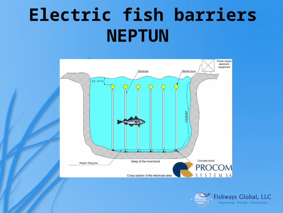
Electric fish barriers NEPTUN
-
Upload
tamara-hebdon -
Category
Documents
-
view
215 -
download
0
Transcript of Electric fish barriers NEPTUN. 1.“Informational” electric field - electric energy absorbed to...
Electric fish barriersNEPTUN

1. “Informational” electric field - electric energy absorbed to scare not to stun the fish.
2. Random alterations – prevent adaptation to constant electric field.
3. Ease of installation 4. Size flexibility5. Resilience and robustness5. Resistance to low temperature (icing).6. Low energy consumption (solar panels for
small barriers)7. Low maintenance costs.
Key Design Features
Integrated
3. How is the system easier to install than the Smith Root version?5. How is this more resistant to icing than the compition? What would happen to the bouys in an ice flow situation in a river?6. We need to have some actual consumption numbers for a small barrier and a definition of the size of a small barrier.7. What is involved in the operation and maintance of the system? Do we have an O&M manual and/or recomendations?
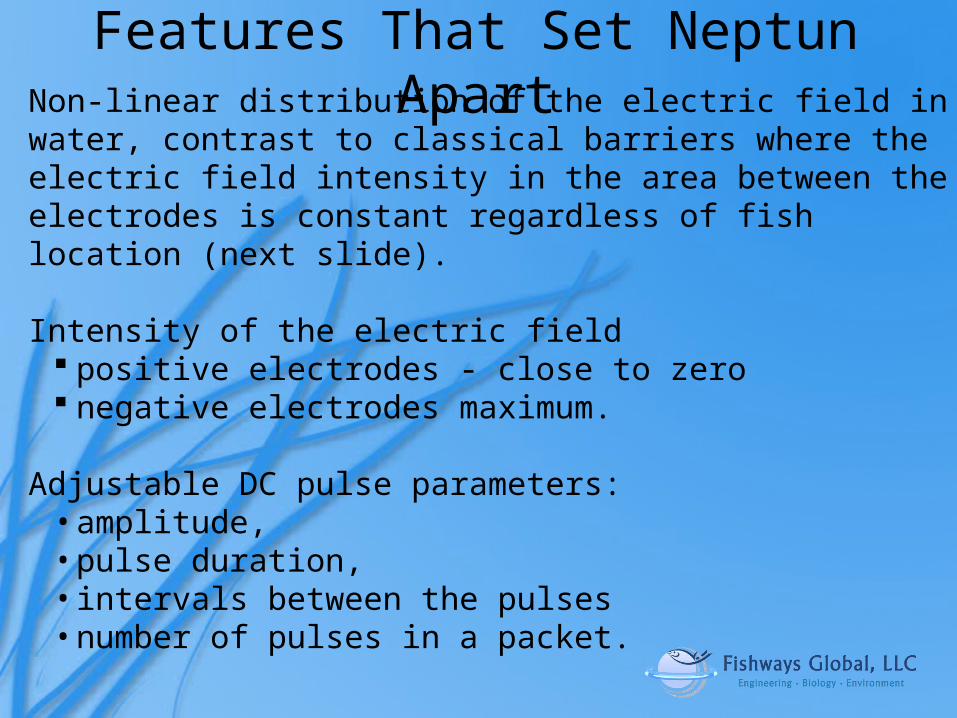
Features That Set Neptun ApartNon-linear distribution of the electric field in water, contrast to classical barriers where the electric field intensity in the area between the electrodes is constant regardless of fish location (next slide). Intensity of the electric field
positive electrodes - close to zero negative electrodes maximum.
Adjustable DC pulse parameters:
• amplitude, • pulse duration, • intervals between the pulses • number of pulses in a packet.
Lenovo Customer
How adjustable are the parameters? What are the upper and lower limits for each DC pulse parameter? Does the system come with preset parameters that are recommeded for typical use. What is the voltage, frequency and pulse rate recomendations. From our recent research it appears that most fish react to an in water electric field of 1 volt/inch excpt asian carp which may require twice the voltage.
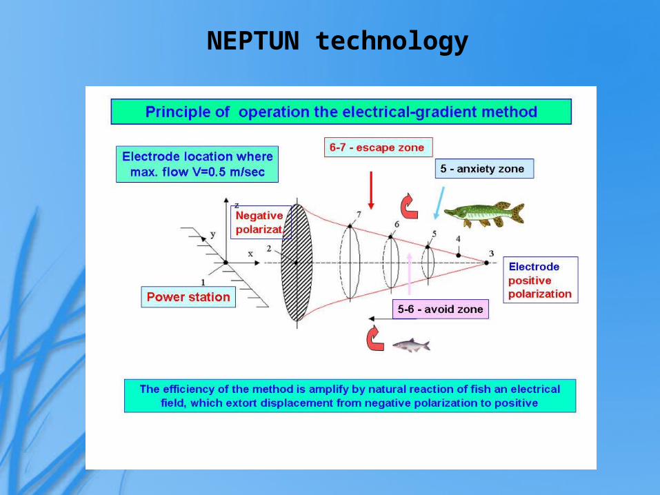
NEPTUN technology
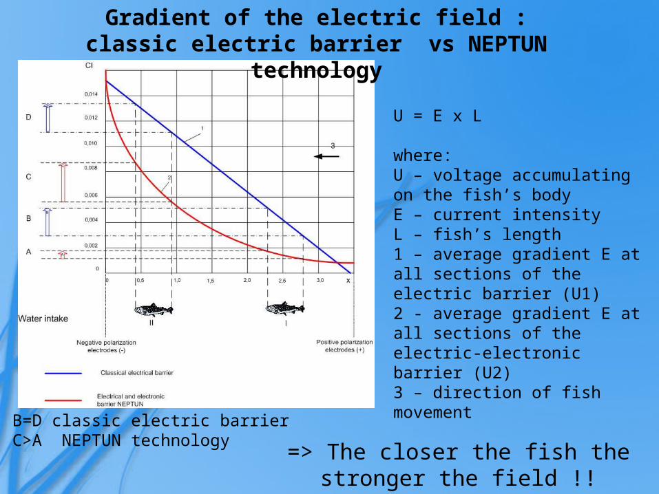
U = E x L where:U – voltage accumulating on the fish’s body E – current intensityL – fish’s length1 – average gradient E at all sections of the electric barrier (U1)2 - average gradient E at all sections of the electric-electronic barrier (U2)3 – direction of fish movement
B=D classic electric barrierC>A NEPTUN technology
Gradient of the electric field :classic electric barrier vs NEPTUN technology
=> The closer the fish the stronger the field !!
Integrated
Units need to be defined on the graph

U = E x L where:U – voltage accumulating on the fish’s body E – current intensityL – fish’s length1 – average gradient E at all sections of the electric barrier (U1)2 - average gradient E at all sections of the electric-electronic barrier (U2)3 – direction of fish movement
A>B>C classic electric barrierA<B<C NEPTUN technology
Gradient of the electric field :classic electric barrier vs NEPTUN technology
=> Size matters but distance matters more!! Selectivity possible.
Jonathan L. Jones
Units need to be defined on the graph

Simplified block diagram of the NEPTUN device
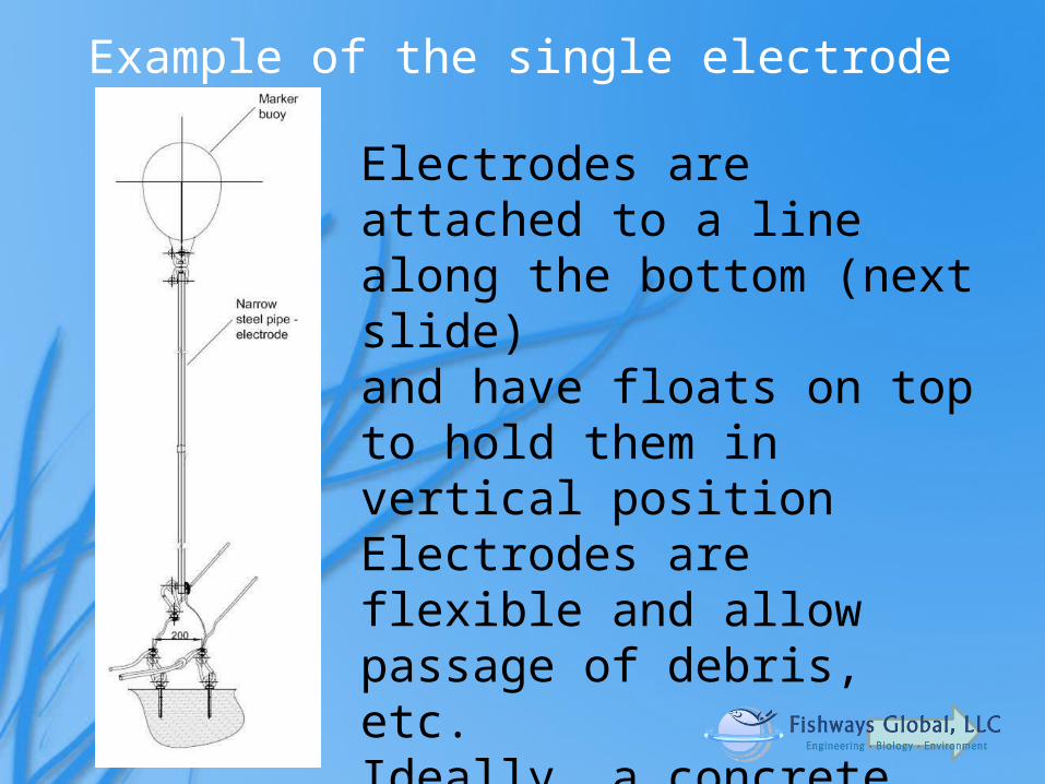
Example of the single electrode
Electrodes are attached to a line along the bottom (next slide)and have floats on top to hold them in vertical positionElectrodes are flexible and allow passage of debris, etc.Ideally, a concrete floor is used to anchor the electrodes, but not necessarily
Integrated
What other mechanisms are available for anchoring these untis to the river bed
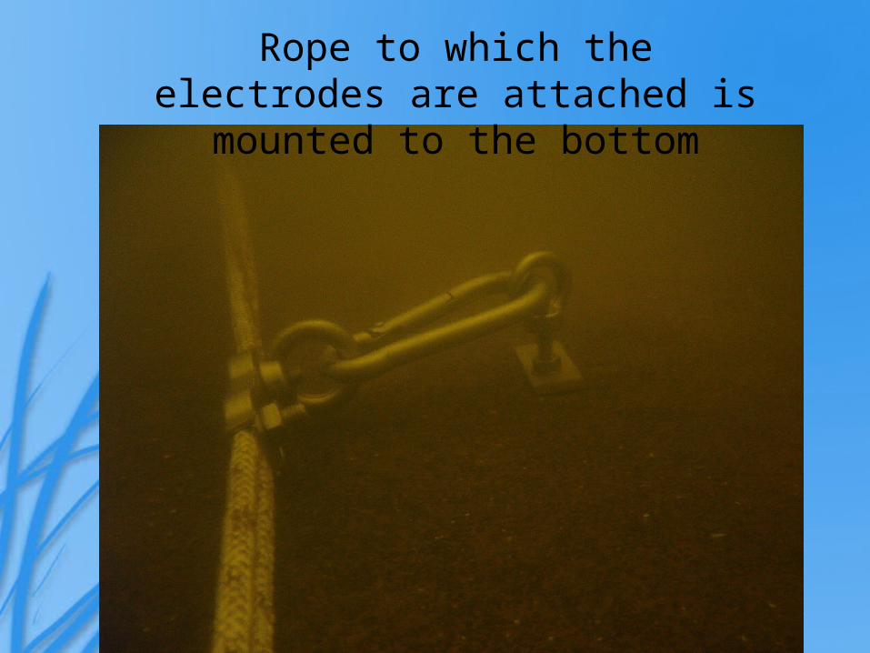
Rope to which the electrodes are attached is mounted to the bottom
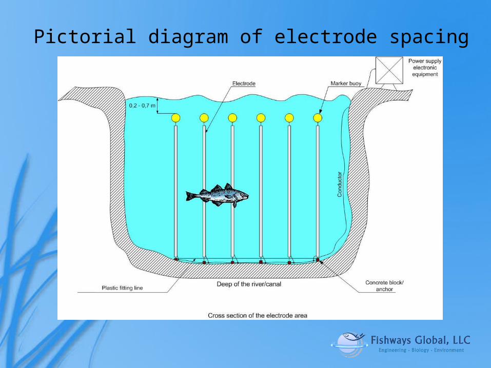
Pictorial diagram of electrode spacing
Jonathan L. Jones
We need to know what this system was designed for, flow rate, width, depth etc.
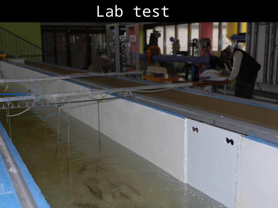
Lab test
Jonathan L. Jones
Our assumption is that the lab test operates the same as the field, even though the electric is attached to the top of the electrode instead of the bottom.What other electic field parameters would be missing from not having the lab demonstration mimic the field installation?
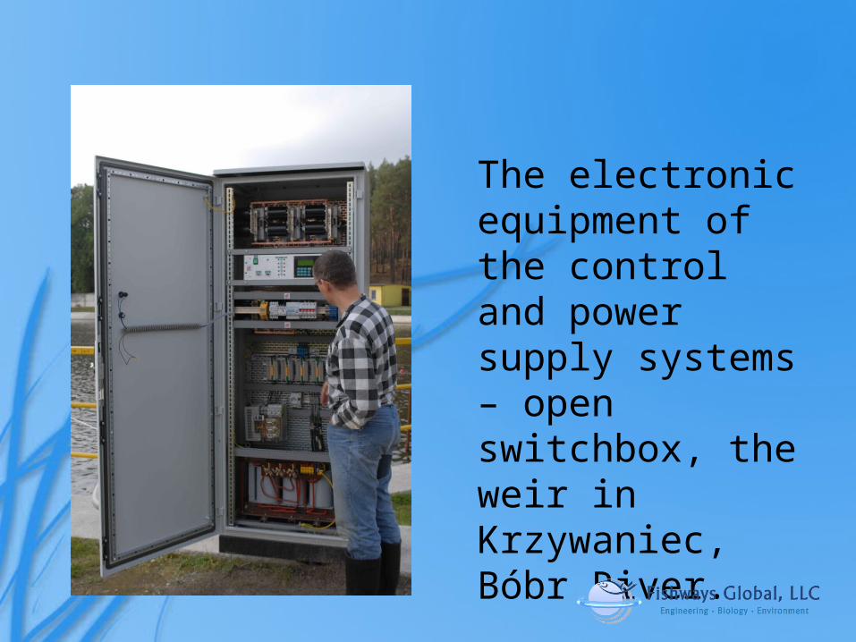
The electronic equipment of the control and power supply systems – open switchbox, the weir in Krzywaniec, Bóbr River.
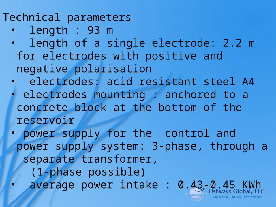
Technical parameters• length : 93 m• length of a single electrode: 2.2 m for electrodes
with positive and negative polarisation• electrodes: acid resistant steel A4• electrodes mounting : anchored to a concrete block
at the bottom of the reservoir • power supply for the control and power supply
system: 3-phase, through a separate transformer, (1-phase possible)
• average power intake : 0.43-0.45 KWh

to Hydropower Plant
ElectrodesNegative polarization (-)
ElectrodesPositive polarization (+)
Electronics
Installation on the weir in Krzywaniec, Bóbr River.
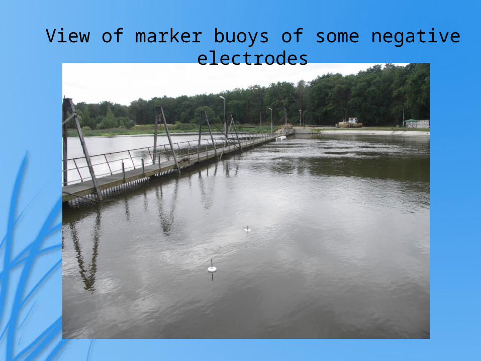
View of marker buoys of some negative electrodes
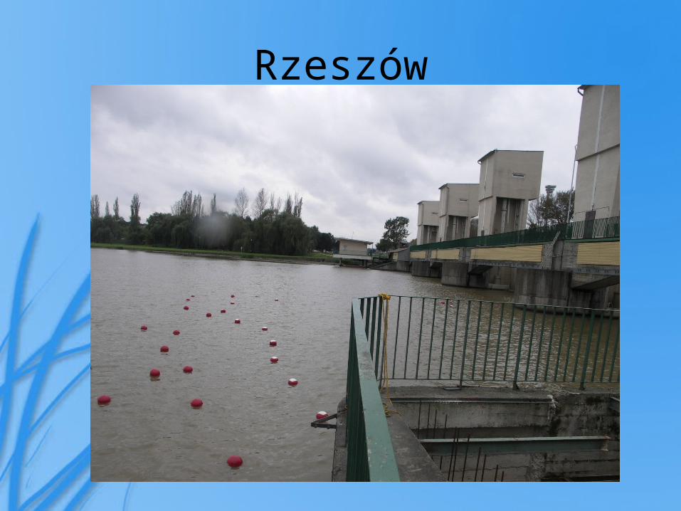
Rzeszów

Szczerców
Integrated
Insert photograph of example site?

Integrated
Insert photograph of example site?Correct spelling to symmetrical - IE can not edit due to the information being inserted as a picture.
Integrated
Insert photograph of example site?
Integrated
Insert photograph of example site?Also, can this type be modified to guide sea lamprey into traps? If so, include this information in the slide.
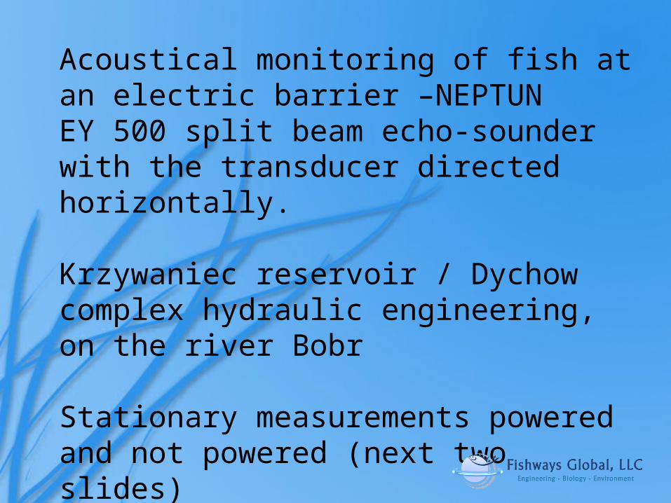
Acoustical monitoring of fish at an electric barrier –NEPTUN EY 500 split beam echo-sounder with the transducer directed horizontally.
Krzywaniec reservoir / Dychow complex hydraulic engineering, on the river Bobr
Stationary measurements powered and not powered (next two slides)

Barrier off…presence of fish between electrodes detected by hi-res sonar
Fish are everywhere; N=283, scanned for 4 minutes
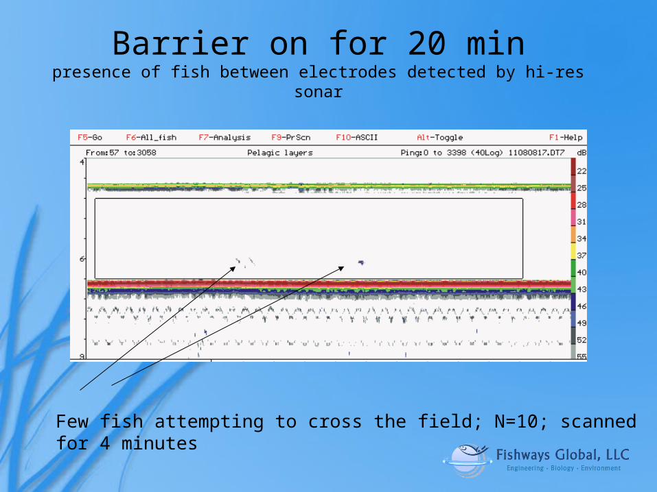
Barrier on for 20 minpresence of fish between electrodes detected by hi-res sonar
Few fish attempting to cross the field; N=10; scanned for 4 minutes
Jonathan L. Jones
What were the operating parameters of the barier during this test; volts per inch, frequency, duration of pulse etc.

Minimum Technical parameters required for design
Design criteria:• Site map showing intake, outlet of turbines, fish-passes; • Depth and electric conductivity of water• Substrate• Mean cross sectional velocity (no greater than 0.5 m/s)• Available power supply (1- or 3-phase)
Jonathan L. Jones
On a "small" system to we need any lined power supply or is solar actually an option?
Neptun Benefits
• Increasing field intensity• Electric field depth-independent • Electric field can be depth-dependent• Low power consumption (solar for small
barriers)• Low operation and maintenance costs• Safer• Electricity does not disperse into the ground• No depth limitation• …
Jonathan L. Jones
Safer needs to be qualified by actual data showing that the unit is safer than the Smith Root system.
Neptun Benefits
• No debris interference• Does not affect navigation• Safety and operation logging• Remote control• Can be installed anywhere (new or retrofit)• Many applications• Low purchase and installation costs• More humane
Integrated
We have concerns that floating debris may damage the vertical electoads by snagging the bouy, this also would include ice flows.Can metal hulled boats pass and touch the electrodes without risk of shock? What if the boat is large enough to touch the positive and negitive electode?We need to have more information on purchase an installation costs (a variety of examples so that we can answer the questions that will be posed by potential clients in a general way).


![What can weakly electric fish tell us about our brains? · Electrolocationin fish “The electric organs of [strongly electric] fishes offer another case of special difficulty; it](https://static.fdocuments.in/doc/165x107/5fd11a409965e2757b43cf93/what-can-weakly-electric-fish-tell-us-about-our-brains-electrolocationin-fish-aoethe.jpg)