Electric Drives Linear Motion and Hydraulics Assembly ... · PDF fileLinear Motion and...
68
Electric Drives and Controls Pneumatics Service Linear Motion and Assembly Technologies Hydraulics
Transcript of Electric Drives Linear Motion and Hydraulics Assembly ... · PDF fileLinear Motion and...

Electric Drivesand Controls Pneumatics Service
Linear Motion and Assembly TechnologiesHydraulics

Rexroth IndraDriveDrive ControllersPower Sections HCS01
Instruction Manual
DOK-INDRV*-HCS01*UL***-IB01-DE-P
RS-49e64cb2ef966abc0a6846a001598e31-1-en-US-3
Edition Release Date Notes
DOK-INDRV*-HCS01*UL***-IB01-DE-P 2009/08 First edition
Purpose of Documentation This documentation provides information on the installation and operation ofthe described products, by persons trained and qualified to work with electricalinstallations.
Copyright © Bosch Rexroth AG, 2009Copying this document, giving it to others and the use or communication of thecontents thereof without express authority, are forbidden. Offenders are liablefor the payment of damages. All rights are reserved in the event of the grant ofa patent or the registration of a utility model or design (DIN 34-1).
Validity The data specified only serve to describe the product. No statements concern‐ing a certain condition or suitability for a certain application can be derived fromour information. The information given does not release the user from the ob‐ligation of own judgement and verification. It must be remembered that ourproducts are subject to a natural process of wear and aging.
Published by Bosch Rexroth AG, Bgm.-Dr.-Nebel-Str. 2, D-97816 Lohr a. MainTelephone +49 (0)93 52 / 40-0, Tx 68 94 21, Fax +49 (0)93 52 / 40-48 85http://www.boschrexroth.deDCC/EDY4 (CR, BB)
Title
Type of Documentation
Document Typecode
Internal File Reference
Record of Revision
Bosch Rexroth AG | Electric Drivesand Controls
Rexroth IndraDrive | Instruction Manual

English Do not attempt to install or put these products into operation until you havecompletely read, understood and observed the documents supplied with theproduct.If no documents in your language were supplied, please consult your Rexrothsales partner.
Deutsch Nehmen Sie die Produkte erst dann in Betrieb, nachdem Sie die mit demProdukt gelieferten Unterlagen und Sicherheitshinweise vollständigdurchgelesen, verstanden und beachtet haben.Sollten Ihnen keine Unterlagen in Ihrer Landessprache vorliegen, wenden Siesich an Ihren zuständigen Rexroth Vertriebspartner.
Français Ne mettez les produits en service qu'après avoir lu complètement et après avoircompris et respecté les documents et les consignes de sécurité fournis avec leproduit.Si vous ne disposez pas de la documentation dans votre langue, merci deconsulter votre partenaire Rexroth.
Italiano Mettere in funzione i prodotti solo dopo aver letto, compreso e osservato perintero la documentazione e le indicazioni di sicurezza fornite con il prodotto.Se non dovesse essere presente la documentazione nella vostra lingua, sietepregati di rivolgervi al rivenditore Rexroth competente.
Español Los productos no se pueden poner en servicio hasta después de haber leídopor completo, comprendido y tenido en cuenta la documentación y lasadvertencias de seguridad que se incluyen en la entrega.Si no dispusiera de documentación en el idioma de su país, diríjase a sudistribuidor competente de Rexroth.
Português (Brasil) Utilize apenas os produtos depois de ter lido, compreendido e tomado emconsideração a documentação e as instruções de segurança fornecidasjuntamente com o produto.Se não tiver disponível a documentação na sua língua dirija-se ao seu parceirode venda responsável da Rexroth.
Nederlands Stel de producten pas in bedrijf nadat u de met het product geleverdedocumenten en de veiligheidsinformatie volledig gelezen, begrepen en in achtgenomen heeft.Mocht u niet beschikken over documenten in uw landstaal, kunt u contactopnemen met uw plaatselijke Rexroth distributiepartner.
Svenska Använd inte produkterna innan du har läst och förstått den dokumentation ochde säkerhetsanvisningar som medföljer produkten, och följ alla anvisningar.Kontakta din Rexroth återförsäljare om dokumentationen inte medföljer på dittspråk.
Suomi Ota tuote käyttöön vasta sen jälkeen, kun olet lukenut läpi tuotteen mukanatoimitetut asiakirjat ja turvallisuusohjeet, ymmärtänyt ne ja ottanut nehuomioon.Jos asiakirjoja ei ole saatavana omalla äidinkielelläsi, ota yhteysasianomaiseen Rexroth myyntiedustajaan.
Polski Produkty wolno uruchamiać dopiero po przeczytaniu wszystkich dokumentówdostarczonych wraz z produktem oraz wskazówek dotyczącychbezpieczeństwa i ich pełnym zrozumieniu. Wszystkich wskazówek tamzawartych należy przestrzegać.Jeżeli brak jest dokumentów w Państwa języku, proszę się skontaktować zlokalnym partnerem handlowym Rexroth.
Instruction Manual | Rexroth IndraDrive Electric Drivesand Controls
| Bosch Rexroth AG I/IV
Český Před uvedením produktů do provozu pročtěte kompletní dokumentaci abezpečnostní pokyny dodávané s produktem a zajistěte, že jim rozumíte abudete se jimi řídit.Nejsou-li k dispozici podklady ve Vaší řeči, obraťte se na příslušného prodejceproduktů Rexroth.
Magyar Mielőtt üzembe helyezné a terméket, olvassa el, értelmezze, és vegyefigyelembe a csomagban található dokumentumban foglaltakat és a biztonságiútmutatásokat.Amennyiben a csomagban nem talál az Ön nyelvén írt dokumentumokat, vegyefel a kapcsolatot az illetékes Rexroth képviselővel.
Română Punerea în funcţiune a produselor trebuie efectuată după citirea, înţelegereaşi respectarea documentelor şi instrucţiunilor de siguranţă, care sunt livrateîmpreună cu produsele.În cazul în care documentele nu sunt în limba dumneavoastră maternă,contactaţi furnizorul dumneavoastră competent pentru Rexroth.
II/IV Bosch Rexroth AG | Electric Drivesand Controls
Rexroth IndraDrive | Instruction Manual

Table of ContentsPage
1 Important Notes............................................................................................................. 51.1 Safety Instructions.................................................................................................................................. 51.1.1 General Information............................................................................................................................. 51.1.2 Protection Against Contact With Electrical Parts and Housings.......................................................... 61.1.3 Protection Against Dangerous Movements......................................................................................... 71.1.4 Protection Against Magnetic and Electromagnetic Fields During Operation and Mounting................ 91.1.5 Protection Against Contact With Hot Parts.......................................................................................... 91.1.6 Protection During Handling and Mounting......................................................................................... 101.2 Appropriate Use.................................................................................................................................... 10
2 Identification................................................................................................................. 112.1 Type Code............................................................................................................................................ 112.2 Type Plates........................................................................................................................................... 122.3 Scope of Supply.................................................................................................................................... 12
3 Ratings and Dimensions.............................................................................................. 13
4 Reference Documentations ........................................................................................ 154.1 Drive Systems, System Components................................................................................................... 154.2 Motors................................................................................................................................................... 154.3 Cables................................................................................................................................................... 154.4 Firmware............................................................................................................................................... 15
5 Instructions for Use...................................................................................................... 175.1 Overcurrent Protection.......................................................................................................................... 175.2 Connection Points................................................................................................................................. 185.2.1 Wiring Diagram.................................................................................................................................. 185.2.2 Connection Diagram.......................................................................................................................... 195.2.3 Connection of Equipment Grounding Conductor............................................................................... 205.2.4 X3, Mains Connection....................................................................................................................... 21
Important Notes.............................................................................................................................. 21HCS01.1E-W0003...W0013-x-02, HCS01.1E-W0005-x-03, HCS01.1E-W0008-x-03.................... 22HCS01.1E-W0018-x-03, HCS01.1E-W0028-x-03.......................................................................... 22
5.2.5 X5, Motor Connection........................................................................................................................ 23Important Notes.............................................................................................................................. 23X5, Motor Connection HCS01.1E-W0003…W0013-x-02, -W0005-x-03, -W0008-x-03................. 23X5, Motor Connection HCS01.1E-W0018-x-03, -W0028-x-03....................................................... 24
5.2.6 X6, Motor Temperature Monitoring and Motor Holding Brake .......................................................... 255.2.7 X9, Integrated/External Braking Resistor.......................................................................................... 265.2.8 X13, 24V Supply (Control Voltage).................................................................................................... 275.2.9 X77, L+ L-, DC Bus Connection........................................................................................................ 285.2.10 Shield Connection............................................................................................................................. 315.2.11 Ground Connection........................................................................................................................... 32
Instruction Manual | Rexroth IndraDrive Electric Drivesand Controls
| Bosch Rexroth AG III/IV
Table of Contents

Page
5.3 Installation............................................................................................................................................. 325.3.1 General Information on How to Install the Drive Controller............................................................... 325.3.2 Sizing of Enclosure and Control Cabinet........................................................................................... 34
Mounting HCS01 Devices in the Control Cabinet........................................................................... 34Multiple-Line Design of the Control Cabinet................................................................................... 35Arrangement of Cooling Units........................................................................................................ 36
6 EMC Measures for Design and Installation.................................................................. 396.1 Rules for Design of Installations With Drive Controllers in Compliance With EMC.............................. 396.2 EMC-Optimal Installation in Facility and Control Cabinet..................................................................... 406.2.1 General Information........................................................................................................................... 406.2.2 Division Into Areas (Zones)............................................................................................................... 406.2.3 Control Cabinet Mounting According to Interference Areas - Exemplary Arrangements.................. 426.2.4 Design and Installation in Area A - Interference-Free Area of Control Cabinet................................. 436.2.5 Design and Installation in Area B - Interference-Susceptible Area of Control Cabinet...................... 456.2.6 Design and Installation in Area C - Strongly Interference-Susceptible Area of Control Cabinet....... 456.3 Ground Connections............................................................................................................................. 466.4 Installing Signal Lines and Signal Cables............................................................................................. 476.5 General Measures of Radio Interference Suppression for Relays, Contactors, Switches, Chokes and
Inductive Loads..................................................................................................................................... 48
7 Accessories.................................................................................................................. 497.1 HAS09.................................................................................................................................................. 497.2 DC Bus Connector................................................................................................................................ 507.3 SUP-E01-MSM-BATTERYBOX............................................................................................................ 517.4 SUP-E03-DKC*CS-BATTRY................................................................................................................ 52
8 Service and Support.................................................................................................... 55
9 Environmental Protection and Disposal ...................................................................... 579.1 Environmental Protection...................................................................................................................... 579.2 Disposal................................................................................................................................................ 57
10 Appendix...................................................................................................................... 5910.1 Discharging of Capacitors..................................................................................................................... 5910.1.1 Discharging of DC Bus Capacitors.................................................................................................... 5910.1.2 Discharging Device............................................................................................................................ 59
Operating Principle......................................................................................................................... 59Dimensioning.................................................................................................................................. 60Installation...................................................................................................................................... 60Activation........................................................................................................................................ 60
Index............................................................................................................................ 61
IV/IV Bosch Rexroth AG | Electric Drivesand Controls
Rexroth IndraDrive | Instruction Manual
Table of Contents

1 Important Notes1.1 Safety Instructions1.1.1 General Information
● Do not attempt to install and operate the components of the electric driveand control system without first reading all documentation provided withthe product. Read and understand these safety instructions and all userdocumentation prior to working with these components. If you do not havethe user documentation for the components, contact your responsibleRexroth sales partner. Ask for these documents to be sent immediately tothe person or persons responsible for the safe operation of the compo‐nents.
● If the supplied documents contain some information you do not under‐stand, it is absolutely necessary that you ask Rexroth for explanationbefore you start working at or with the components.
● If the component is resold, rented and/or passed on to others in any otherform, these safety instructions must be delivered with the component inthe official language of the user's country.
● Only qualified persons may work with components of the electric drive andcontrol system or within its proximity.In terms of this Instruction Manual, qualified persons are those personswho are familiar with the installation, mounting, commissioning and oper‐ation of the components of the electric drive and control system, as wellas with the hazards this implies, and who possess the qualifications theirwork requires. To comply with these qualifications, it is necessary, amongother things,– to be trained, instructed or authorized to switch electric circuits and
components safely on and off, to ground them and to mark them,– to be trained or instructed to maintain and use adequate safety
equipment,– to attend a course of instruction in first aid.
● The technical data, connection and installation conditions of the compo‐nents are specified in the respective application documentations and mustbe followed at all times.
● If the components take the form of hardware, then they must remain intheir original state, in other words, no structural changes are permitted. Itis not permitted to decompile software components or alter source codes.
● Do not mount damaged or faulty components or use them in operation.● Only use accessories and spare parts approved by Rexroth.● Follow the safety regulations and requirements of the country in which the
electric components of the electric drive and control system are operated.● Proper and correct transport, storage, mounting and installation, as well
as care in operation and maintenance, are prerequisites for optimal andsafe operation of the component.
WARNING
Improper use of these components, failure to follow the safety instruc‐tions in this document or tampering with the product, including disablingof safety devices, could result in property damage, injury, electric shockor even death.Observe the safety instructions!
Instruction Manual | Rexroth IndraDrive Electric Drivesand Controls
| Bosch Rexroth AG 5/65
Important Notes
1.1.2 Protection Against Contact With Electrical Parts and HousingsThis section concerns components of the electric drive and controlsystem with voltages of more than 50 volts.
Contact with parts conducting voltages above 50 volts can cause personaldanger and electric shock. When operating components of the electric driveand control system, it is unavoidable that some parts of these componentsconduct dangerous voltage.
WARNING
High electrical voltage! Danger to life, risk of injury by electric shock orserious injury!● Only qualified persons are allowed to operate, maintain and/or repair the
components of the electric drive and control system.● Follow the general installation and safety regulations when working on
power installations.● Before switching on, the equipment grounding conductor must have been
permanently connected to all electric components in accordance with theconnection diagram.
● Even for brief measurements or tests, operation is only allowed if theequipment grounding conductor has been permanently connected to thepoints of the components provided for this purpose.
● Before accessing electrical parts with voltage potentials higher than 50 V,you must disconnect electric components from the mains or from the pow‐er supply unit. Secure the electric component from reconnection.
● With electric components, observe the following aspects:Always wait 30 minutes after switching off power to allow live capacitorsto discharge before accessing an electric component. Measure the elec‐trical voltage of live parts before beginning to work to make sure that theequipment is safe to touch.
● Install the covers and guards provided for this purpose before switchingon.
● Never touch electrical connection points of the components while poweris turned on.
● Do not remove or plug in connectors when the component has been pow‐ered.
● Under specific conditions, electric drive systems can be operated at mainsprotected by residual-current-operated circuit-breakers sensitive to uni‐versal current (RCDs/RCMs).
● Secure built-in devices from penetrating foreign objects and water, as wellas from direct contact, by providing an external housing, for example acontrol cabinet.
6/65 Bosch Rexroth AG | Electric Drivesand Controls
Rexroth IndraDrive | Instruction Manual
Important Notes

WARNING
High housing voltage and high leakage current! Danger to life, risk ofinjury by electric shock!● Before switching on and before commissioning, ground or connect the
components of the electric drive and control system to the equipmentgrounding conductor at the grounding points.
● Connect the equipment grounding conductor of the components of theelectric drive and control system permanently to the main power supply atall times. The leakage current is greater than 3.5 mA.
● Establish an equipment grounding connection with a copper wire of across section of at least 10 mm2 (8 AWG) or additionally run a secondequipment grounding conductor of the same cross section as the originalequipment grounding conductor.
1.1.3 Protection Against Dangerous MovementsDangerous movements can be caused by faulty control of connected motors.Some common examples are:● Improper or wrong wiring or cable connection● Operator errors● Wrong input of parameters before commissioning● Malfunction of sensors and encoders● Defective components● Software or firmware errorsDangerous movements can occur immediately after equipment is switched onor even after an unspecified time of trouble-free operation.The monitoring functions in the components of the electric drive and controlsystem will normally be sufficient to avoid malfunction in the connected drives.Regarding personal safety, especially the danger of injury and/or property dam‐age, this alone cannot be relied upon to ensure complete safety. Until theintegrated monitoring functions become effective, it must be assumed in anycase that faulty drive movements will occur. The extent of faulty drive move‐ments depends upon the type of control and the state of operation.
Instruction Manual | Rexroth IndraDrive Electric Drivesand Controls
| Bosch Rexroth AG 7/65
Important Notes
WARNING
Dangerous movements! Danger to life, risk of injury, serious injury orproperty damage!● A risk assessment must be prepared for the installation or machine, with
its specific conditions, in which the components of the electric drive andcontrol system are installed. As a result of the risk assessment, the usermust provide for monitoring functions and higher-level measures on theinstallation side for personal safety. The safety regulations applicable tothe installation or machine must be taken into consideration. Unintendedmachine movements or other malfunctions are possible if safety devicesare disabled, bypassed or not activated.
To avoid accidents, injury and/or property damage:● Keep free and clear of the machine’s range of motion and moving machine
parts. Prevent personnel from accidentally entering the machine’s rangeof motion by using, for example:– Safety fences– Safety guards– Protective coverings– Light barriers
● Make sure the safety fences and protective coverings are strong enoughto resist maximum possible kinetic energy.
● Mount EMERGENCY STOP switches in the immediate reach of the op‐erator. Before commissioning, verify that the EMERGENCY STOP equip‐ment works. Do not operate the machine if the EMERGENCY STOPswitch is not working.
● Prevent unintended start-up. Isolate the drive power connection by meansof OFF switches/buttons or use a safe starting lockout.
● Make sure that the drives are brought to a safe standstill before accessingor entering the danger zone.
● Additionally secure vertical axes against falling or dropping after switchingoff the motor power by, for example,– mechanically securing the vertical axis,– adding an external braking/ arrester/ clamping mechanism or– ensuring sufficient equilibration of the vertical axis.
● The standard equipment motor holding brake or an external holding brakecontrolled by the drive controller is not sufficient to guarantee personalsafety!
● Disconnect electrical power to the components of the electric drive andcontrol system using the master switch and secure them from reconnec‐tion for:– Maintenance and repair work– Cleaning of equipment– Long periods of discontinued equipment use
● Prevent the operation of high-frequency, remote control and radio equip‐ment near components of the electric drive and control system and theirsupply leads. If the use of these devices cannot be avoided, check themachine or installation, at initial commissioning of the electric drive andcontrol system, for possible malfunctions when operating such high-fre‐quency, remote control and radio equipment in its possible positions ofnormal use. It might possibly be necessary to perform a special electro‐magnetic compatibility (EMC) test.
8/65 Bosch Rexroth AG | Electric Drivesand Controls
Rexroth IndraDrive | Instruction Manual
Important Notes
1.1.4 Protection Against Magnetic and Electromagnetic Fields During Oper‐ation and Mounting
Magnetic and electromagnetic fields generated by current-carrying conductorsor permanent magnets of electric motors represent a serious danger to personswith heart pacemakers, metal implants and hearing aids.
WARNING
Health hazard for persons with heart pacemakers, metal implants andhearing aids in proximity to electric components!● Persons with heart pacemakers and metal implants are not allowed to
enter the following areas:– Areas in which components of the electric drive and control systems
are mounted, commissioned and operated.– Areas in which parts of motors with permanent magnets are stored,
repaired or mounted.● If it is necessary for somebody with a heart pacemaker to enter such an
area, a doctor must be consulted prior to doing so. The noise immunity ofimplanted heart pacemakers differs greatly so that no general rules canbe given.
● Those with metal implants or metal pieces, as well as with hearing aids,must consult a doctor before they enter the areas described above.
1.1.5 Protection Against Contact With Hot Parts
CAUTION
Hot surfaces of components of the electric drive and control system.Risk of burns!● Do not touch hot surfaces of, for example, braking resistors, heat sinks,
supply units and drive controllers, motors, windings and laminated cores!● According to the operating conditions, temperatures of the surfaces can
be higher than 60 °C (140 °F) during or after operation.● Before touching motors after having switched them off, let them cool down
for a sufficiently long time. Cooling down can require up to 140 minutes!The time required for cooling down is approximately five times the thermaltime constant specified in the technical data.
● After switching chokes, supply units and drive controllers off, wait 15 mi‐nutes to allow them to cool down before touching them.
● Wear safety gloves or do not work at hot surfaces.● For certain applications and according to the respective safety regulations,
the manufacturer of the machine or installation has to take measures toavoid injuries caused by burns in the end application. These measurescan be, for example: Warnings at the machine or installation, guards(shieldings or barriers) or safety instructions in the application documen‐tation.
Instruction Manual | Rexroth IndraDrive Electric Drivesand Controls
| Bosch Rexroth AG 9/65
Important Notes
1.1.6 Protection During Handling and Mounting
CAUTION
Risk of injury by improper handling! Injury by crushing, shearing, cutting,hitting!● Observe the relevant statutory regulations of accident prevention.● Use suitable equipment for mounting and transport.● Avoid jamming and crushing by appropriate measures.● Always use suitable tools. Use special tools if specified.● Use lifting equipment and tools in the correct manner.● Use suitable protective equipment (hard hat, safety goggles, safety shoes,
safety gloves, for example).● Do not stand under hanging loads.● Immediately clean up any spilled liquids from the floor due to the risk of
slipping.
1.2 Appropriate UseThis product may only be used for the applications mentioned in the referencedocumentations (see index entry "Reference documentations") and under thedescribed application, ambient and operating conditions.This product is exclusively intended for use in machines and systems in anindustrial environment. This is to be understood as applications according toIEC 60204-1 "Safety of machinery, Electric equipment of machines" andNFPA 79 "Electrical Standard for Industrial Machinery".
Components of the drive system Rexroth IndraDrive Cs are prod‐ucts of category C3 (with restricted distribution) according toIEC 61800‑3. These components are not provided for use in a publiclow-voltage mains supplying residential areas. If these componentsare used in such a mains, high-frequency interference is to be ex‐pected. This can require additional measures of radio interferencesuppression.
10/65 Bosch Rexroth AG | Electric Drivesand Controls
Rexroth IndraDrive | Instruction Manual
Important Notes

2 Identification2.1 Type Code
Fig.2-1: Type Code HCS01
Instruction Manual | Rexroth IndraDrive Electric Drivesand Controls
| Bosch Rexroth AG 11/65
Identification
The figure illustrates the basic structure of the type code. Our salesrepresentative will help you with the current status of available ver‐sions.
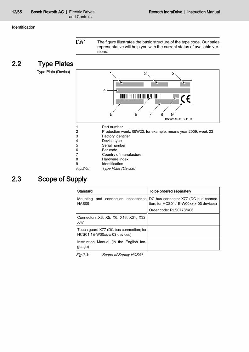
2.2 Type PlatesType Plate (Device)
1 Part number2 Production week; 09W23, for example, means year 2009, week 233 Factory identifier4 Device type5 Serial number6 Bar code7 Country of manufacture8 Hardware index9 IdentificationFig.2-2: Type Plate (Device)
2.3 Scope of SupplyStandard To be ordered separately
Mounting and connection accessoriesHAS09
DC bus connector X77 (DC bus connec‐tion; for HCS01.1E-W00xx-x-03 devices)Order code: RLS0778/K06
Connectors X3, X5, X6, X13, X31, X32,X47
Touch guard X77 (DC bus connection; forHCS01.1E-W00xx-x-03 devices)
Instruction Manual (in the English lan‐guage)
Fig.2-3: Scope of Supply HCS01
12/65 Bosch Rexroth AG | Electric Drivesand Controls
Rexroth IndraDrive | Instruction Manual
Identification

3 Ratings and DimensionsUL Ratings and Dimensions
Description Symbol Unit
HCS01.1E-W0003-_-02
HCS01.1E-W0006-_-02
HCS01.1E-W0009-_-02
HCS01.1E-W0013-_-02
HCS01.1E-W0005-_-03
HCS01.1E-W0008-_-03
HCS01.1E-W0018-_-03
HCS01.1E-W0028-_-03
Listing according to UL standard(UL) UL 508 C
Listing according to CSA standard(UL) Canadian National Standard(s) C22.2 No. 14-05
UL files (UL) E 134201
Ambient temperature with nominaldata (UL)
Tamax °C 40
Ambient temperature with reducednominal data (UL)
Tamax_red °C 55
Mass (weight) m kg 0,72 1,70
Device height (UL)1) H mm 215 268
Device depth (UL)2) T mm 196
Device width (UL)3) B mm 50 70
Minimum distance on the top of thedevice4) dtop mm 100
Minimum distance on the bottom ofthe device5) dbot mm 100
Horizontal spacing on the device6) dhor mm 10 0
Rated control voltage input (UL)7) UN3 V 24 ± 5%
Rated power consumption controlvoltage input at UN3 (UL) 8) PN3 W 27 28 27 28 34
Short circuit current rating (UL) SCCR A rms 42000
Rated input voltage, power (UL) 9) ULN_nenn V 3 x AC 110...230 3 x AC 200...500
Tolerance rated input voltage (UL) % ± 10
Input frequency (UL) fLN Hz 50...60
Tolerance input frequency (UL) Hz ± 2
Rated input current (UL) ILN A 0,6 1,2 2,3 4,5 1,5 2,5 5,0 10,0
Branch circuit protection fuse(UL)10) 2 4 6 2 4 10 16
Required wire size according toEN 60204‑111) ALN mm2 1,5
Required wire size according to UL508 A (internal wiring); (UL)12) ALN AWG AWG 14
Output voltage (UL) Uout V 3 x AC 0...230 3 x AC 0...500
Last modification: 2009-07-28
Instruction Manual | Rexroth IndraDrive Electric Drivesand Controls
| Bosch Rexroth AG 13/65
Ratings and Dimensions

Description Symbol Unit
HCS01.1E-W0003-_-02
HCS01.1E-W0006-_-02
HCS01.1E-W0009-_-02
HCS01.1E-W0013-_-02
HCS01.1E-W0005-_-03
HCS01.1E-W0008-_-03
HCS01.1E-W0018-_-03
HCS01.1E-W0028-_-03
Output current (UL) Iout A 1,1 2,0 3,0 4,5 1,7 2,7 6,0 11,5
Output frequency range (UL)13) fout Hz 0...1600
Power dissipation at continuouscurrent and continuous DC buspower respectively (UL)14)
PDiss_cont W 8,00 10,00 12,00 20,00 11,00 46,00 80,00 120,00
Last modification: 2009-07-28
1) 2) 3) Housing dimension; see also related dimensional drawing4) 5) 6) See fig. "Air Intake and Air Outlet at Device"7) Observe supply voltage for motor holding brakes8) HMS, HMD, HCS plus motor holding brake and control section; HCS01
including control section9) DC bus L+, L-; mains input L1, L2, L310) Use listed AC input line fuses (class J; 600 V AC) or listed circuit break‐
ers (600 V AC) at the mains supply11) Copper wire; PVC-insulation (conductor temperature 70 °C); installation
method B1; table 612) Copper wire; PVC-insulation (conductor temperature 90 °C); table
13.5.1; Ta ≤ 40 °C13) Depending on switching frequency which was set in parameter P‑0‑000114) Plus dissipation of braking resistor and control sectionFig.3-1: HCS - UL Ratings and Dimensions
Distances
A Air intakeB Air outletC Mounting surface in control cabinetdtop Distance topdbot Distance bottomdhor Distance horizontalFig.3-2: Air Intake and Air Outlet at Device
14/65 Bosch Rexroth AG | Electric Drivesand Controls
Rexroth IndraDrive | Instruction Manual
Ratings and Dimensions

4 Reference Documentations 4.1 Drive Systems, System ComponentsTitleRexroth IndraDrive …
Kind of documentation Document typecode1)
DOK-INDRV*-…Part number
R911…
Cs Drive Systems Project Planning Manual HCS01******-PRxx-EN-P 322210
1) In the document typecodes, "xx" is a wild card for the current edition ofthe documentation (example: PR01 is the first edition of a Project Plan‐ning Manual)
Fig.4-1: Documentations – Drive Systems, System Components
4.2 MotorsTitleRexroth IndraDyn …
Kind of documentation Document typecode1)
DOK-MOTOR*-…Part number
R911…
S MSK Synchronous Motors Project Planning Manual MSK********-PRxx-EN-P 296289
S Synchronous Motors MSM Data Sheet MSM********-DAxx-EN-P 329338
1) In the document typecodes, "xx" is a wild card for the current edition ofthe documentation (example: PR01 is the first edition of a Project Plan‐ning Manual)
Fig.4-2: Documentations – Motors
4.3 CablesTitle Kind of documentation Document typecode1)
DOK-CONNEC-…Part number
R911…
Rexroth Connection Cables Selection Data CABLE*STAND-AUxx-EN-P 282688
1) In the document typecodes, "xx" is a wild card for the current edition ofthe documentation (example: AU03 is the third edition of the documen‐tation "Selection Data")
Fig.4-3: Documentations – Cables
4.4 FirmwareTitleRexroth IndraDrive …
Kind of documentation Document typecode1)
DOK-INDRV*-…Part number
R911…
MPB-16, MPM-16, MPE-16Functions
Application Manual MP*-16VRS**-APxx-EN-P 326767
MPB-16, MPM-16, MPE-16Version Notes
Release Notes MP*-16VRS**-RNxx-EN-P 329272
MPx-16Parameters
Reference Book GEN1-PARA**-RE01-EN-P 328651
MPx-16Diagnostic Messages
Reference Book GEN1-DIAG**-RE01-EN-P 326738
1) In the document typecodes, "xx" is a wild card for the current edition ofthe documentation (example: RE02 is the second edition of a referencedocumentation)
Fig.4-4: Documentations – Firmware
Instruction Manual | Rexroth IndraDrive Electric Drivesand Controls
| Bosch Rexroth AG 15/65
Reference Documentations

16/65 Bosch Rexroth AG | Electric Drivesand Controls
Rexroth IndraDrive | Instruction Manual

5 Instructions for Use5.1 Overcurrent Protection
Protect the components against overcurrent:● Branch circuit protection has to be provided externally● Dimension the branch circuit protection according to the data "Branch cir‐
cuit protection fuse (UL)" (see Ratings and Dimensions)
Instruction Manual | Rexroth IndraDrive Electric Drivesand Controls
| Bosch Rexroth AG 17/65
Instructions for Use

5.2 Connection Points5.2.1 Wiring Diagram
24V Control voltage supplyC DC bus capacitor unit (for devices with DC bus connection)COM CommunicationDST Autotransformer; optionalF FusesHCS01 ConverterNF Mains filter; optional (depends on EMC requirements)HNL Mains choke; optionalK1 External mains contactorM Motor (MSM, MSK)RB Braking resistor (at the back of the drive controller)Fig.5-1: Drive System Rexroth IndraDrive Cs
18/65 Bosch Rexroth AG | Electric Drivesand Controls
Rexroth IndraDrive | Instruction Manual
Instructions for Use

5.2.2 Connection Diagram
X47 Module bus (X47.3…6) only at HCS01.1E-W00xx-x-03 devices; for sig‐naling the readiness for operation of the device, the Bb relay contact(X47.1, X47.2) must be wired, too
X77 (L+, L-) Only at HCS01.1E-W00xx-x-03 devicesT1, T2 Not available at MSM motorsFig.5-2: Connection Diagram
Instruction Manual | Rexroth IndraDrive Electric Drivesand Controls
| Bosch Rexroth AG 19/65
Instructions for Use

5.2.3 Connection of Equipment Grounding Conductor
WARNING
High housing voltage and high leakage current! Danger to life, risk ofinjury by electric shock!● Before switching on and before commissioning, ground or connect the
components of the electric drive and control system to the equipmentgrounding conductor at the grounding points.
● Connect the equipment grounding conductor of the components of theelectric drive and control system permanently to the main power supply atall times. The leakage current is greater than 3.5 mA.
● Establish an equipment grounding connection with a copper wire of across section of at least 10 mm2 (8 AWG) or additionally run a secondequipment grounding conductor of the same cross section as the originalequipment grounding conductor.
WARNING
Lethal electric shock by live parts with more than 50 V!Exclusively operate the device● with plugged on connectors (even if there haven't been any lines connec‐
ted to the connectors) and● with connected equipment grounding conductor!
Equipment grounding conductor: Material and cross sectionFor the equipment grounding conductor, use the same metal (e.g.copper) as for the outer conductors.For the connections from the equipment grounding conductor con‐nection of the device to the equipment grounding conductor systemin the control cabinet, make sure the cross sections of the lines aresufficient.Cross sections of the equipment grounding connections:For HCS01 drive controllers, at least 10 mm2, but not smaller thanthe cross sections of the outer conductors of the mains supply feed‐er.Additionally, mount the housing to a bare metal mounting plate.Connect the mounting plate, too, with at least the same cross sec‐tion to the equipment grounding conductor system in the controlcabinet.
Installation Connect the equipment grounding conductor of the mains or motor cable viathread M5 to the housing of the device (identification mark ). The screwsM5×12 required for this purpose are part of the supplied accessory HAS09.
20/65 Bosch Rexroth AG | Electric Drivesand Controls
Rexroth IndraDrive | Instruction Manual
Instructions for Use

L1, L2, L3 Mains connectionA1, A2, A3 Motor connectionFig.5-3: Connection Point of Equipment Grounding Conductor
5.2.4 X3, Mains ConnectionImportant Notes
WARNING
Lethal electric shock by live parts with more than 50 V!Exclusively operate the device● with plugged on connectors (even if there haven't been any lines connec‐
ted to the connectors) and● with connected equipment grounding conductor!
Notes on Installation The equipment grounding conductor is connected directly to the device and notvia the connection point X3 (see description for connection of equipmentgrounding conductor).Dimension the required cross section of the connection cables according to thedetermined phase current ILN and the mains fuse.
CAUTION
Risk of damage to the device!Provide strain relief for the terminal connectors of the device in the control cab‐inet.
Instruction Manual | Rexroth IndraDrive Electric Drivesand Controls
| Bosch Rexroth AG 21/65
Instructions for Use

HCS01.1E-W0003...W0013-x-02, HCS01.1E-W0005-x-03, HCS01.1E-W0008-x-03HCS01.1E-W0003...W0013-x-02, HCS01.1E-W0005-x-03, HCS01.1E-W0008-x-03
View Identifica‐tion
Function
L1 Connection to supply mains (L1)
L2 Connection to supply mains (L2)
L3 Connection to supply mains (L3)
Terminal block Unit Min. Max.
Connection cableStranded wire
mm2 0,25 2,5
AWG 24 12
Stripped length mm 8
Occurring current load and minimum requiredconnection cross section
See technical data of device used (ILN and ALN)
Occurring voltage load See technical data of device used (ULN or ULN_nenn)
Fig.5-4: Function, Pin Assignment, Properties
HCS01.1E-W0018-x-03, HCS01.1E-W0028-x-03HCS01.1E-W0018-x-03, HCS01.1E-W0028-x-03
View Identifica‐tion
Function
L1 Connection to supply mains (L1)
L2 Connection to supply mains (L2)
L3 Connection to supply mains (L3)
Terminal block Unit Min. Max.
Connection cableStranded wire
mm2 0,25 6,0
AWG 24 8
Stripped length mm 10
Occurring current load and minimum requiredconnection cross section
See technical data of device used (ILN and ALN)
Occurring voltage load See technical data of device used (ULN or ULN_nenn)
Fig.5-5: Function, Pin Assignment, Properties
22/65 Bosch Rexroth AG | Electric Drivesand Controls
Rexroth IndraDrive | Instruction Manual
Instructions for Use

5.2.5 X5, Motor ConnectionImportant Notes
WARNING
Lethal electric shock by live parts with more than 50 V!Exclusively operate the device● with plugged on connectors (even if there haven't been any lines connec‐
ted to the connectors) and● with connected equipment grounding conductor!
CAUTION
Risk of damage to the device!Provide strain relief for the terminal connectors of the device in the control cab‐inet.
Notes on Installation The equipment grounding conductor is connected directly to the device and not
via the connection point X5 (see description for connection of equipmentgrounding conductor).The indicated connection cross sections are the cross sections which can beconnected. Dimension the required cross section of the connection lines ac‐cording to the occurring current load.
● For optimum shield contact of the motor power cable, use thesupplied accessory HAS09.
● For the connection between drive controller and motor, useour ready-made motor power cables, where possible (seedocumentation "Rexroth Connection Cables").
● When using NFD03.1 mains filters, the maximum allowed con‐ductor cross section is limited to 4 mm2.
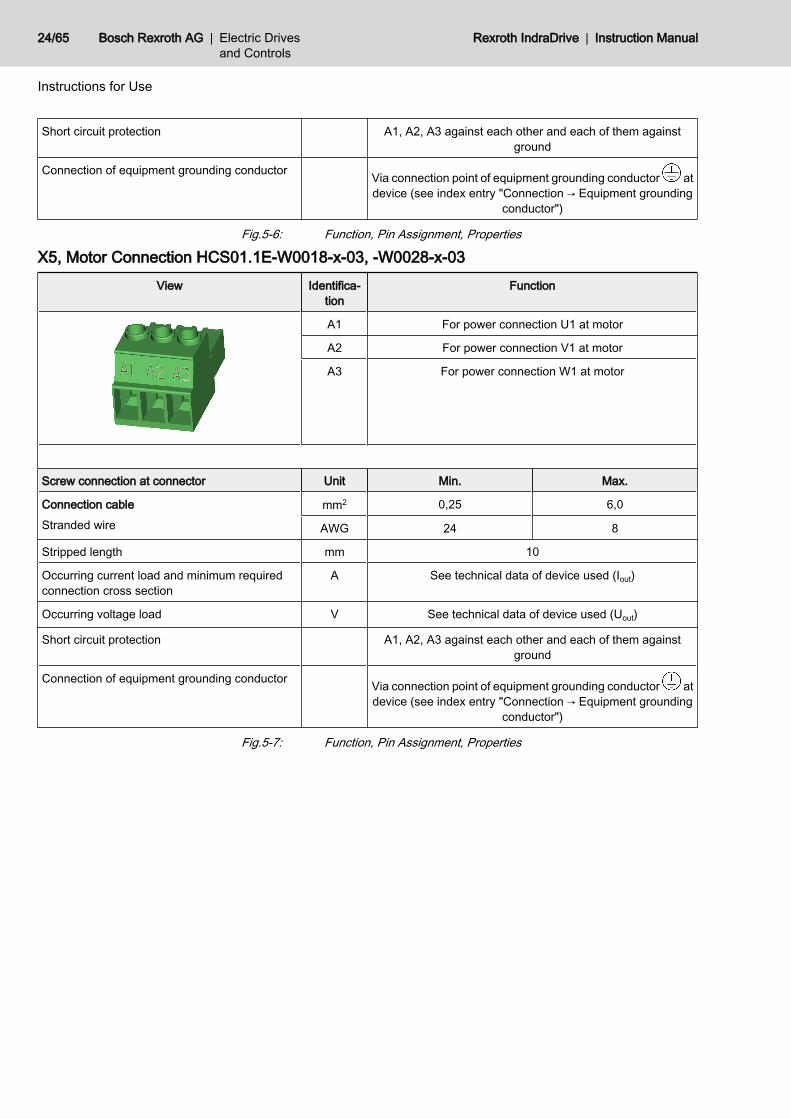
X5, Motor Connection HCS01.1E-W0003…W0013-x-02, -W0005-x-03, -W0008-x-03View Identifica‐
tionFunction
A1 For power connection U1 at motor
A2 For power connection V1 at motor
A3 For power connection W1 at motor
Screw connection at connector Unit Min. Max.
Connection cableStranded wire
mm2 0,25 2,5
AWG 24 12
Stripped length mm 8
Occurring current load and minimum requiredconnection cross section
A See technical data of device used (Iout)
Occurring voltage load V See technical data of device used (Uout)
Instruction Manual | Rexroth IndraDrive Electric Drivesand Controls
| Bosch Rexroth AG 23/65
Instructions for Use
Short circuit protection A1, A2, A3 against each other and each of them againstground
Connection of equipment grounding conductor Via connection point of equipment grounding conductor atdevice (see index entry "Connection → Equipment grounding
conductor")
Fig.5-6: Function, Pin Assignment, Properties
X5, Motor Connection HCS01.1E-W0018-x-03, -W0028-x-03View Identifica‐
tionFunction
A1 For power connection U1 at motor
A2 For power connection V1 at motor
A3 For power connection W1 at motor
Screw connection at connector Unit Min. Max.
Connection cableStranded wire
mm2 0,25 6,0
AWG 24 8
Stripped length mm 10
Occurring current load and minimum requiredconnection cross section
A See technical data of device used (Iout)
Occurring voltage load V See technical data of device used (Uout)
Short circuit protection A1, A2, A3 against each other and each of them againstground
Connection of equipment grounding conductor Via connection point of equipment grounding conductor atdevice (see index entry "Connection → Equipment grounding
conductor")
Fig.5-7: Function, Pin Assignment, Properties
24/65 Bosch Rexroth AG | Electric Drivesand Controls
Rexroth IndraDrive | Instruction Manual
Instructions for Use

5.2.6 X6, Motor Temperature Monitoring and Motor Holding Brake
WARNING
Dangerous movements! Danger to persons from falling or dropping ax‐es!The standard motor holding brake provided or an external motor holding brakecontrolled directly by the drive controller are not sufficient on their own to guar‐antee personal safety!Personal safety must be achieved using higher-level, fail-safe measures:● Block off danger zones with safety fences or safety guards● Additionally secure vertical axes against falling or dropping after switching
off the motor power by, for example,– mechanically securing the vertical axes– adding external braking/arrester/clamping mechanisms– ensuring sufficient equilibration of the vertical axes
Function The connection point X6 contains the connections for● monitoring the motor temperature● controlling the motor holding brake
Via an integrated contact element (BR), the power section switchesthe voltage of the external 24V supply to the output for controllingthe motor holding brake.
View Connec‐tion
Signal name Function
1 MotTemp+ Input motor temperature eval‐uation2 MotTemp-
3 +24VBr Output for controlling the mo‐tor holding brake4 0VBr
Spring terminal (connector) Unit Min. Max.
Connection cableStranded wire
mm2 0,25 1,5
AWG 24 16
Stripped length mm 10
Current carrying capacity outputs X6:
HCS01.1 A - 1,25
Time constant of load ms - 50
Number of switching actions at maximum timeconstant of load
250.000
Switching frequency Hz - 0,5
Instruction Manual | Rexroth IndraDrive Electric Drivesand Controls
| Bosch Rexroth AG 25/65
Instructions for Use
Short circuit protection X6.3 against X6.4 (output for controlling the motor holdingbrake)
Overload protection X6.3 against X6.4 (output for controlling the motor holdingbrake)
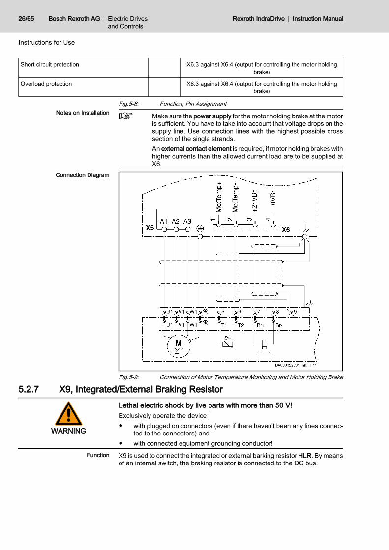
Fig.5-8: Function, Pin AssignmentNotes on Installation Make sure the power supply for the motor holding brake at the motor
is sufficient. You have to take into account that voltage drops on thesupply line. Use connection lines with the highest possible crosssection of the single strands.An external contact element is required, if motor holding brakes withhigher currents than the allowed current load are to be supplied atX6.
Connection Diagram
Fig.5-9: Connection of Motor Temperature Monitoring and Motor Holding Brake
5.2.7 X9, Integrated/External Braking Resistor
WARNING
Lethal electric shock by live parts with more than 50 V!Exclusively operate the device● with plugged on connectors (even if there haven't been any lines connec‐
ted to the connectors) and● with connected equipment grounding conductor!
Function X9 is used to connect the integrated or external barking resistor HLR. By meansof an internal switch, the braking resistor is connected to the DC bus.
26/65 Bosch Rexroth AG | Electric Drivesand Controls
Rexroth IndraDrive | Instruction Manual
Instructions for Use

Parameterize the external braking resistor by means of the firmwareto protect the drive controller and the braking resistor against over‐load:● P-0-0860, Converter configuration● P-0-0858, Data of external braking resistor
Fig.5-10: Connection of Braking ResistorNotes on Installation Maximum allowed line length to external braking resistor: 5 m
Twist unshielded lines.
5.2.8 X13, 24V Supply (Control Voltage)Function, Pin Assignment The external 24V supply is applied via connection point X13 for
● the control section and power section of the drive controller● brake control via X6● the digital inputs and the digital output to X31 / X32
View Connec‐tion
Signal name Function
1 0V Reference potential for powersupply2 0V
3 +24V Power supply
4 +24V
Spring terminal (connector) Unit Min. Max.
Connection cableStranded wire
mm2 1,0 2,5
AWG 16 12
Stripped length mm 10
Power consumption W PN3 (see data for control voltage)
Voltage load capacity V UN3 (see data for control voltage)
Instruction Manual | Rexroth IndraDrive Electric Drivesand Controls
| Bosch Rexroth AG 27/65
Instructions for Use

Current carrying capacity "looping through" from0V to 0V, 24V to 24V
A 10
Polarity reversal protection Within the allowed voltage range by internal protective diode
Insulation monitoring Possible
Fig.5-11: Function, Pin Assignment, PropertiesNotes on Installation Requirements on the connection to the 24V supply:
● Minimum cross section: 1 mm2
● Maximum allowed inductance: 100 µH (2 twisted single strands, 75 mlong)
● Parallel line routing where possibleDepending on the power consumption of the devices and the current carryingcapacity of the connector X13, check via how many devices one line for 24Vsupply can be looped through. You might possibly have to connect anotherdevice directly to the 24V supply and then loop through the control voltage fromthis device to other devices.
5.2.9 X77, L+ L-, DC Bus Connection
WARNING
Lethal electric shock by live parts with more than 50 V!Before working on live parts: De-energize installation and secure power switchagainst unintentional or unauthorized re-energization.Before accessing the device, wait at least 30 minutes after switching off thesupply voltages to allow discharging. To shorten the waiting time until voltagehas fallen below 50 V, you can use a discharging device (see chapter "Appen‐dix").Check whether voltage has fallen below 50 V before touching live parts!Never operate the drive controller without touch guard or without DC bus con‐nector. Only remove the touch guard, if you want to use the DC bus connectorat the drive controller. If you do not use the DC bus connector any longer, youhave to cover the DC bus connection with the supplied touch guard.
Function, Pin Assignment The DC bus connection connects
● several HCS01.1E-W00xx-x-03 to each other● one drive controller to a DC bus capacitor unit (to backup the DC bus
voltage)
Touch Guard The DC bus connection has been provided with a touch guard at the factory.To plug the DC bus connector, you have to remove the tough guard.
28/65 Bosch Rexroth AG | Electric Drivesand Controls
Rexroth IndraDrive | Instruction Manual
Instructions for Use

How to Remove the Touch Guard:
UDC DC bus voltage30 Min. ! Before accessing the device, wait at least 30 minutes after switching off
the supply voltages to allow discharging.1. With a small screwdriver (blade width < 3 mm), push the fixing device
outwards and simultaneously lever out the touch guard.2. Pull off touch guard.3. Store the touch guard in a place where you can find it later on. If you
want to operate the device without DC bus connector, you have to haveto plug the touch guard on connection point X77 again.
Fig.5-12: How to Remove the Touch Guard
Fig.5-13: DC Bus Connector at Device
Instruction Manual | Rexroth IndraDrive Electric Drivesand Controls
| Bosch Rexroth AG 29/65
Instructions for Use
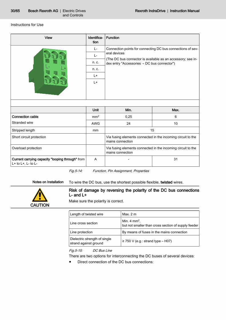
View Identifica‐tion
Function
L- Connection points for connecting DC bus connections of sev‐eral devices(The DC bus connector is available as an accessory; see in‐dex entry "Accessories → DC bus connector")
L-
n. c.
n. c.
L+
L+
Unit Min. Max.
Connection cableStranded wire
mm2 0,25 6
AWG 24 10
Stripped length mm 15
Short circuit protection Via fusing elements connected in the incoming circuit to themains connection
Overload protection Via fusing elements connected in the incoming circuit to themains connection
Current carrying capacity "looping through" fromL+ to L+, L‑ to L‑
A - 31
Fig.5-14: Function, Pin Assignment, Properties
Notes on Installation To wire the DC bus, use the shortest possible flexible, twisted wires.
CAUTION
Risk of damage by reversing the polarity of the DC bus connectionsL- and L+Make sure the polarity is correct.
Length of twisted wire Max. 2 m
Line cross section Min. 4 mm2, but not smaller than cross section of supply feeder
Line protection By means of fuses in the mains connection
Dielectric strength of singlestrand against ground ≥ 750 V (e.g.: strand type – H07)
Fig.5-15: DC Bus LineThere are two options for interconnecting the DC buses of several devices:● Direct connection of the DC bus connections:
30/65 Bosch Rexroth AG | Electric Drivesand Controls
Rexroth IndraDrive | Instruction Manual
Instructions for Use
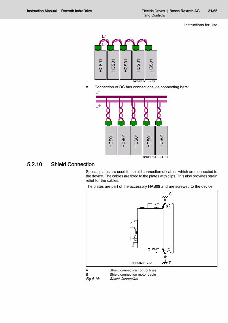
● Connection of DC bus connections via connecting bars:
5.2.10 Shield ConnectionSpecial plates are used for shield connection of cables which are connected tothe device. The cables are fixed to the plates with clips. This also provides strainrelief for the cables.The plates are part of the accessory HAS09 and are screwed to the device.
A Shield connection control linesB Shield connection motor cableFig.5-16: Shield Connection
Instruction Manual | Rexroth IndraDrive Electric Drivesand Controls
| Bosch Rexroth AG 31/65
Instructions for Use
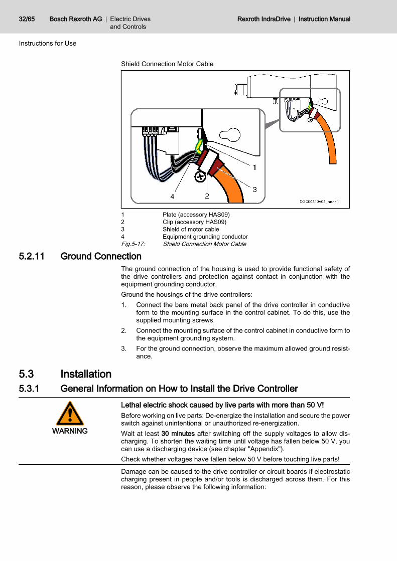
Shield Connection Motor Cable
1 Plate (accessory HAS09)2 Clip (accessory HAS09)3 Shield of motor cable4 Equipment grounding conductorFig.5-17: Shield Connection Motor Cable
5.2.11 Ground ConnectionThe ground connection of the housing is used to provide functional safety ofthe drive controllers and protection against contact in conjunction with theequipment grounding conductor.Ground the housings of the drive controllers:1. Connect the bare metal back panel of the drive controller in conductive
form to the mounting surface in the control cabinet. To do this, use thesupplied mounting screws.
2. Connect the mounting surface of the control cabinet in conductive form tothe equipment grounding system.
3. For the ground connection, observe the maximum allowed ground resist‐ance.
5.3 Installation5.3.1 General Information on How to Install the Drive Controller
WARNING
Lethal electric shock caused by live parts with more than 50 V!Before working on live parts: De-energize the installation and secure the powerswitch against unintentional or unauthorized re-energization.Wait at least 30 minutes after switching off the supply voltages to allow dis‐charging. To shorten the waiting time until voltage has fallen below 50 V, youcan use a discharging device (see chapter "Appendix").Check whether voltages have fallen below 50 V before touching live parts!
Damage can be caused to the drive controller or circuit boards if electrostaticcharging present in people and/or tools is discharged across them. For thisreason, please observe the following information:
32/65 Bosch Rexroth AG | Electric Drivesand Controls
Rexroth IndraDrive | Instruction Manual
Instructions for Use
CAUTION
Electrostatic charges can cause damage to electronic components andinterfere with their operational safety!Exposed conductive parts coming into contact with components and circuitboards must be discharged by means of grounding. Otherwise errors may occurwhen controlling motors and moving elements.
Such exposed conductive parts include:● The copper bit when soldering● The human body (ground connection by touching a conductive, grounded
object)● Parts and tools (place them on a conductive support)Endangered components may only be stored or dispatched in conductive pack‐aging.
Rexroth connection diagrams are only to be used for producing in‐stallation circuit diagrams! The machine manufacturer’s installationcircuit diagrams must be used for wiring the installation!
● Lay signal lines separately from the load resistance lines because of theoccurrence of interference.
● Transmit analog signals (e.g. command values, actual values) via shiel‐ded lines.
● Do not connect mains, DC bus or power cores to low voltages or allowthem to come into contact with these.
● When carrying out a high voltage test or an applied-overvoltage withstandtest on the machine’s electrical equipment, disconnect all connections tothe devices. This protects the electronic components (allowed in accord‐ance with EN 60204-1). During their routine testing, Rexroth drive com‐ponents are tested for high voltage and insulation in accordance withEN 50178.
CAUTION
Risk of damage to the drive controller by connecting and disconnectinglive connections!Do not connect and disconnect live connections.
Instruction Manual | Rexroth IndraDrive Electric Drivesand Controls
| Bosch Rexroth AG 33/65
Instructions for Use

5.3.2 Sizing of Enclosure and Control CabinetMounting HCS01 Devices in the Control Cabinet
1 Control cabinet wall2 Left-hand mounting3 Back-side mounting (standard mounting)4 Right-hand mountingFig.5-18: Options for Mounting HCS01 Devices in the Control Cabinet
Notes on Mounting ● The back-side mounting (back of device directly mounted to control cab‐inet wall) is the standard and should be used, if possible.
● The left-hand or right-hand mounting (left or right side of device directlymounted to control cabinet wall) can be used, if the mounting clearancebetween control cabinet wall and control cabinet front is not sufficient forback-side mounting.CAUTION! Risk of damage by high temperatures! At the back of theHCS01 devices, there are braking resistors which can become very hotduring operation. When arranging the devices in the control cabinet, makesure there aren't any heat-sensitive materials close to the braking resis‐tors.In the case of left-hand or right-hand mounting, you must not pile the de‐vices. Each device must have immediate contact to the control cabinetwall.
● Observe the minimum distances to be complied with for mounting (seetechnical data or dimensional drawings).The specified horizontal minimum distance refers to the distance to neigh‐boring devices and not to the distance to the control cabinet wall.
● Tightening torque of the mounting screws: 6 Nm● On the sides of the devices, there are adhesive labels with notes on safe‐
ty. The supplied accessory HAS09 additionally contains these adhesivelabels. If the adhesive labels at the devices are no longer visible aftermounting, place the adhesive labels from the accessory HAS09 clearlyvisibly at the device or in the immediate vicinity of the device.
Required Steps to Follow HCS01 drive controllers were designed for control cabinet mounting. They aremounted with two screws (M6×20; contained in the supplied accesso‐ry HAS09).
34/65 Bosch Rexroth AG | Electric Drivesand Controls
Rexroth IndraDrive | Instruction Manual
Instructions for Use

Mounting the drive controller1. Fix screws to the back panel of the control cabinet.2. Attach the drive controller to the screws.3. Fix the screws with 6 Nm.
Multiple-Line Design of the Control Cabinet
Arrangement of the devices, air guides/drip protections, blowersPay particular attention to the maximum allowed air intake temper‐ature of devices when they are arranged in multiple lines in thecontrol cabinet.If possible, place devices with a high degree of power dissipation(e.g. supply units with braking resistors, DC bus resistor units)● in the top line and● near the outlet air aperture to the cooling unitMount air guides between the lines to● protect the devices in the upper lines against the warm outlet
air of the devices beneath and● protect the devices beneath against penetration of liquids (e.g.
dripping condensation water or leaking cooling liquid)Additional blowers convey the outlet air to the cooling unit and cool‐ing air to the upper lines.At the installed control cabinet, check the air intake temperature ofall devices.
Instruction Manual | Rexroth IndraDrive Electric Drivesand Controls
| Bosch Rexroth AG 35/65
Instructions for Use
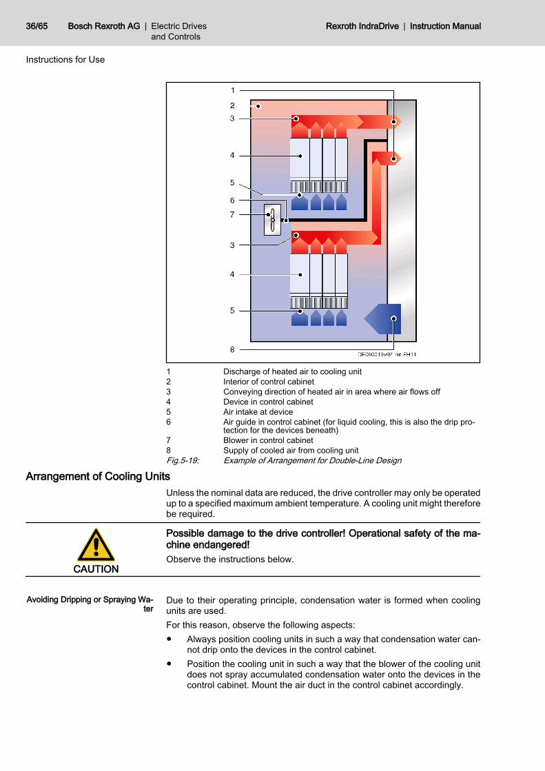
1 Discharge of heated air to cooling unit2 Interior of control cabinet3 Conveying direction of heated air in area where air flows off4 Device in control cabinet5 Air intake at device6 Air guide in control cabinet (for liquid cooling, this is also the drip pro‐
tection for the devices beneath)7 Blower in control cabinet8 Supply of cooled air from cooling unitFig.5-19: Example of Arrangement for Double-Line Design
Arrangement of Cooling UnitsUnless the nominal data are reduced, the drive controller may only be operatedup to a specified maximum ambient temperature. A cooling unit might thereforebe required.
CAUTION
Possible damage to the drive controller! Operational safety of the ma‐chine endangered!Observe the instructions below.
Avoiding Dripping or Spraying Wa‐
terDue to their operating principle, condensation water is formed when coolingunits are used.For this reason, observe the following aspects:● Always position cooling units in such a way that condensation water can‐
not drip onto the devices in the control cabinet.● Position the cooling unit in such a way that the blower of the cooling unit
does not spray accumulated condensation water onto the devices in thecontrol cabinet. Mount the air duct in the control cabinet accordingly.
36/65 Bosch Rexroth AG | Electric Drivesand Controls
Rexroth IndraDrive | Instruction Manual
Instructions for Use

Cooling Unit on Top of the Control Cabinet Cooling Unit at the Front of the Control Cabinet
1 Cooling unit2 Interior of control cabinet3 Air duct (protects devices against condensation water)4 Device in control cabinetFig.5-20: Arrangement of Cooling Units
Avoiding Moisture Condensation Moisture condensation occurs when the temperature of the device is lower thanthe ambient temperature.● Set cooling units with temperature adjustment to the maximum surround‐
ing temperature and not lower!● Set cooling units with follow-up temperature in such a way that the interior
temperature of the control cabinet is not lower than the temperature of thesurrounding air. Set the temperature limitation to the maximum surround‐ing temperature!
● Only use well-sealed control cabinets so that moisture condensation can‐not arise as a result of warm and moist external air entering the cabinet.
● In the event that control cabinets are operated with the doors open (com‐missioning, servicing etc.), it is essential to ensure that after the doors areclosed the drive controllers cannot at any time be cooler than the air in thecontrol cabinet. For this reason, sufficient circulation must be providedinside the control cabinet.
Instruction Manual | Rexroth IndraDrive Electric Drivesand Controls
| Bosch Rexroth AG 37/65
Instructions for Use

38/65 Bosch Rexroth AG | Electric Drivesand Controls
Rexroth IndraDrive | Instruction Manual

6 EMC Measures for Design and Installation6.1 Rules for Design of Installations With Drive Controllers in Com‐
pliance With EMCThe following rules are the basics for designing and installing drives in compli‐ance with EMC.
Mains Filter Correctly use a mains filter recommended by Rexroth for radio interferencesuppression in the supply feeder of the drive system.
Control Cabinet Grounding Connect all metal parts of the cabinet with one another over the largest possiblesurface area to establish a good electrical connection. This, too, applies to themounting of the mains filter. If required, use serrated washers which cut throughthe paint surface. Connect the cabinet door to the control cabinet using theshortest possible grounding straps.
Line Routing Avoid coupling routes between lines with high potential of noise and noise-freelines; therefore, signal, mains and motor lines and power cables have to berouted separately from another. Minimum distance: 10 cm. Provide separatingsheets between power and signal lines. Ground separating sheets severaltimes.The lines with high potential of noise include:● Lines at the mains connection (incl. synchronization connection)● Lines at the motor connection
Lines at the DC bus connectionGenerally, interference injections are reduced by routing cables close to groun‐ded sheet steel plates. For this reason, cables and wires should not be routedfreely in the cabinet, but close to the cabinet housing or mounting panels. Sep‐arate the incoming and outgoing cables of the radio interference suppressionfilter.
Interference Suppression Elements Provide the following components in the control cabinet with interference sup‐pression combinations:● Contactors● Relays● Solenoid valves● Electromechanical operating hours countersConnect these combinations directly at each coil.
Twisted Wires Twist unshielded wires belonging to the same circuit (feeder and return cable)or keep the surface between feeder and return cable as small as possible. Wiresthat are not used have to be grounded at both ends.
Lines of Measuring Systems Lines of measuring systems must be shielded. Connect the shield to ground atboth ends and over the largest possible surface area. The shield may not beinterrupted, e.g. using intermediate terminals.
Digital Signal Lines Ground the shields of digital signal lines at both ends (transmitter and receiver)over the largest possible surface area and with low impedance. In the case ofbad ground connection between transmitter and receiver, additionally route abonding conductor (min. 10 mm2). Braided shields are better than foil shields.
Analog Signal Lines Ground the shields of analog signal lines at one end (transmitter or receiver)over the largest possible surface area and with low impedance. This avoids low-frequency interference current (in the mains frequency range) on the shield.
Instruction Manual | Rexroth IndraDrive Electric Drivesand Controls
| Bosch Rexroth AG 39/65
EMC Measures for Design and Installation
Connection of Mains Choke Keep connection lines of the mains choke at the drive controller as short aspossible and twist them.
Installation of Motor Power Cable ● Use shielded motor power cables or run motor power cables in a shieldedduct
● Use the shortest possible motor power cables● Ground shield of motor power cable at both ends over the largest possible
surface area to establish a good electrical connection● Run motor lines in shielded form inside the control cabinet● Do not use any steel-shielded lines● The shield of the motor power cable mustn't be interrupted by mounted
components, such as output chokes, sine filters or motor filters
6.2 EMC-Optimal Installation in Facility and Control Cabinet6.2.1 General Information
For EMC-optimal installation, a spatial separation of the interference-free area(mains connection) and the interference-susceptible area (drive components)is recommended, as shown in the figures below.
For EMC-optimal installation in the control cabinet, use a separatecontrol cabinet panel for the drive components.
6.2.2 Division Into Areas (Zones)Exemplary arrangements in the control cabinet: See section Control CabinetMounting According to Interference Areas - Exemplary Arrangements,page 42.We distinguish three areas:1. Interference-free area of control cabinet (area A):
This includes:● Supply feeder, input terminals, fuse, main switch, mains side of
mains filter for drives and corresponding connecting lines● Control voltage or auxiliary voltage connection with power supply
unit, fuse and other parts unless connection is run via the mains filterof the AC drives
● All components that are not electrically connected with the drive sys‐tem
2. Interference-susceptible area (area B):● Mains connections between drive system and mains filter for drives,
mains contactor● Interface lines of drive controller
3. Strongly interference-susceptible area (area C):● Motor power cables including single cores
Never run lines of one of these areas in parallel with lines of another area sothat there isn't any unwanted interference injection from one area to the otherand that the filter is jumpered with regard to high frequency. Use the shortestpossible connecting lines.Recommendation for complex systems: Install drive components in one cabinetand the control units in a second, separate cabinet.
40/65 Bosch Rexroth AG | Electric Drivesand Controls
Rexroth IndraDrive | Instruction Manual
EMC Measures for Design and Installation

Badly grounded control cabinet doors act as antennas. Therefore, connect thecontrol cabinet doors to the cabinet on top, in the middle and on the bottom viashort equipment grounding conductors with a cross section of at least 6 mm2
or, even better, via grounding straps with the same cross section. Make sureconnection points have good contact.
Instruction Manual | Rexroth IndraDrive Electric Drivesand Controls
| Bosch Rexroth AG 41/65
EMC Measures for Design and Installation
6.2.3 Control Cabinet Mounting According to Interference Areas - ExemplaryArrangements
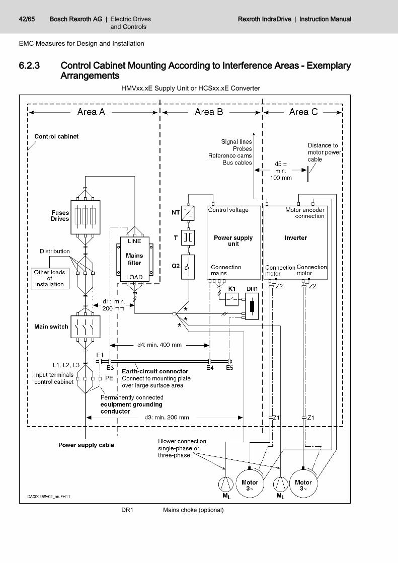
HMVxx.xE Supply Unit or HCSxx.xE Converter
DR1 Mains choke (optional)
42/65 Bosch Rexroth AG | Electric Drivesand Controls
Rexroth IndraDrive | Instruction Manual
EMC Measures for Design and Installation
E1…E5 Equipment grounding conductor of the componentsK1 External mains contactor for supply units and converters without inte‐
grated mains contactorML Motor blowerNT Power supply unitQ2 FusingT TransformerZ1, Z2 Shield connection points for cables* Not allowed at HNF mains filterFig.6-1: HMVxx.xE; HCSxx.xE – EMC Areas in the Control Cabinet
6.2.4 Design and Installation in Area A - Interference-Free Area of ControlCabinet
Arrangement of the Components inthe Control Cabinet
Comply with a distance of at least 200 mm (distance d1 in the figure):● Between components and electrical elements (switches, pushbuttons,
fuses, terminal connectors) in the interference-free area A and the com‐ponents in the two other areas B and C
Comply with a distance of at least 400 mm (distance d4 in the figure):● Between magnetic components (such as transformers, mains chokes and
DC bus chokes that are directly connected to the power connections ofthe drive system) and the interference-free components and lines betweenmains and filter including the mains filter in area A
If these distances are not kept, the magnetic leakage fields are injected to theinterference-free components and lines connected to the mains and the limitvalues at the mains connection are exceeded in spite of the installed filter.
Cable Routing of the Interference-Free Lines to the Mains Connection
Comply with a distance of at least 200 mm (distance d1 and d3 in the figure):● Between supply feeder or lines between filter and exit point from the con‐
trol cabinet in area A and the lines in area B and CIf this is impossible, there are two alternatives:1. Install lines in shielded form and connect the shield at several points (at
least at the beginning and at the end of the line) to the mounting plate orthe control cabinet housing over a large surface area.
2. Separate lines from the other interference-susceptible lines in areas B andC by means of a grounded distance plate vertically attached to the mount‐ing plate.
Install the shortest possible lines within the control cabinet and install themdirectly on the grounded metal surface of the mounting plate or of the controlcabinet housing.Mains supply lines from areas B and C must not be connected to the mainswithout a filter.
In case you do not observe the information on cable routing givenin this section, the effect of the mains filter is totally or partly neu‐tralized. This will cause the noise level of the interference emissionto be higher within the range of 150 kHz to 40 MHz and the limitvalues at the connection points of the machine or installation willthereby be exceeded.
Routing and Connecting a NeutralConductor (N)
If a neutral conductor is used together with a three-phase connection, it mustnot be installed unfiltered in zones B and C, in order to keep interference off themains.
Instruction Manual | Rexroth IndraDrive Electric Drivesand Controls
| Bosch Rexroth AG 43/65
EMC Measures for Design and Installation

Motor Blower at Mains Filter Single-phase or three-phase supply lines of motor blowers, that are usuallyrouted in parallel with motor power cables or interference-susceptible lines,must be filtered:● In drive systems with regenerative supply units, via a separate single-
phase (NFE type) or three-phase filter (HNF type) near the mains con‐nection of the control cabinet
● In drive systems with only infeeding supply units, via the available three-phase filter of the drive system
When switching power off, make sure the blower is not switched off.Loads at Mains Filter of Drive Sys‐
tem Only operate allowed loads at the mains filter of the drive system!At the three-phase filter for the power connection of regenerativesupply units, it is only allowed to operate the following loads:● HMV supply unit with mains choke and, if necessary, mains
contactorDo not operate any motor blowers, power supply units etc. at themains filter of the drive system.
Shielding Mains Supply Lines inControl Cabinet
If there is a high degree of interference injection to the mains supply line withinthe control cabinet, although you have observed the above instructions (to befound out by EMC measurement according to standard), proceed as follows:● Only use shielded lines in area A● Connect shields to the mounting plate at the beginning and the end of the
line by means of clipsThe same procedure may be required for long cables of more than 2 m betweenthe point of power supply connection of the control cabinet and the filter withinthe control cabinet.
Mains Filters for AC Drives Ideally, mount the mains filter on the parting line between area A and B. Makesure the ground connection between filter housing and housing of the drivecontrollers has good electrically conductive properties.If single-phase loads are connected on the load side of the filter, their currentmay be a maximum of 10% of the three-phase operating current. A highly im‐balanced load of the filter would deteriorate its interference suppression ca‐pacity.If the mains voltage is more than 480 V, connect the filter to the output side ofthe transformer and not to the supply side of the transformer.
Grounding In the case of bad ground connections in the installation, the distance betweenthe lines to the grounding points E1, E2 in area A and the other grounding pointsof the drive system should be at least d4 = 400 mm, in order to minimize inter‐ference injection from ground and ground cables to the power input lines.See also 6.2.2 Division Into Areas (Zones), page 40.
Point of Connection for EquipmentGrounding Conductor at Machine,
Installation, Control Cabinet
The equipment grounding conductor of the power cable of the machine, instal‐lation or control cabinet has to be permanently connected at point PE and havea cross section of at least 10 mm2 or to be complemented by a second equip‐ment grounding conductor via separate terminal connectors (according toEN50178/ 1997, section 5.3.2.1). If the cross section of the outer conductor isbigger, the cross section of the equipment grounding conductor must be ac‐cordingly bigger.
44/65 Bosch Rexroth AG | Electric Drivesand Controls
Rexroth IndraDrive | Instruction Manual
EMC Measures for Design and Installation

6.2.5 Design and Installation in Area B - Interference-Susceptible Area ofControl Cabinet
Arranging Components and Lines Modules, components and lines in area B should be placed at a distance of atleast d1 = 200 mm from modules and lines in area A.Alternative: Shield modules, components and lines in area B by distance platesmounted vertically on the mounting plate from modules and lines in area A oruse shielded lines.Only connect power supply units for auxiliary or control voltage connections inthe drive system to the mains via a mains filter. See 6.2.2 Division Into Areas(Zones), page 40.Install the shortest possible lines between drive controller and filter.
Control Voltage or Auxiliary VoltageConnection
Only in exceptional cases should you connect power supply unit and fusing forthe control voltage connection to phase and neutral conductor. In this case,mount and install these components in area A far away from the areas B andC of the drive system. For details see section 6.2.4 Design and Installation inArea A - Interference-Free Area of Control Cabinet, page 43.Run the connection between control voltage connection of the drive system andpower supply unit used through area B over the shortest distance.
Line Routing Run the lines along grounded metal surfaces, in order to minimize radiation ofinterference fields to area A (transmitting antenna effect).
6.2.6 Design and Installation in Area C - Strongly Interference-SusceptibleArea of Control Cabinet
Area C mainly concerns the motor power cables, especially at the connectionpoint at the drive controller.
Influence of the Motor Power Cable The longer the motor power cable, the greater its leakage capacitance. Tocomply with a certain EMC limit value, the allowed leakage capacitance of themains filter is limited. For the calculation of the leakage capacitance, see thedocumentation on the drive system of the drive controller used.
● Run the shortest possible motor power cables.● Only use shielded motor power cables by Rexroth.
Routing the Motor Power Cablesand Motor Encoder Cables
Route the motor power cables and motor encoder cables along grounded metalsurfaces, both inside the control cabinet and outside of it, in order to minimizeradiation of interference fields. If possible, route the motor power cables andmotor encoder cables in metal-grounded cable ducts.Route the motor power cables and motor encoder cables● with a distance of at least d5 = 100 mm to interference-free lines, as well
as to signal cables and signal lines(alternatively separated by a grounded distance plate)
● in separate cable ducts, if possibleRouting the Motor Power Cables
and Mains Connection LinesFor converters (drive controllers with individual mains connection), route motorpower cables and (unfiltered) mains connection lines in parallel for a maximumdistance of 300 mm. After that distance, route motor power cables and powersupply cables in opposite directions and preferably in separate cable ducts.Ideally, the outlet of the motor power cables at the control cabinet should beprovided in a distance of at least d3 = 200 mm from the (filtered) power supplycable.
Instruction Manual | Rexroth IndraDrive Electric Drivesand Controls
| Bosch Rexroth AG 45/65
EMC Measures for Design and Installation
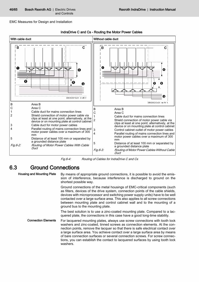
IndraDrive C and Cs - Routing the Motor Power Cables
With cable duct Without cable duct
B Area BC Area C1 Cable duct for mains connection lines2 Shield connection of motor power cable via
clips at least at one point; alternatively, at thedevice or on mounting plate at control cabinet
3 Cable duct for motor power cables4 Parallel routing of mains connection lines and
motor power cables over a maximum of 300mm
5 Distance of at least 100 mm or separated bya grounded distance plate
Fig.6-2: Routing of Motor Power Cables With CableDuct
B Area BC Area C1 Cable duct for mains connection lines2 Shield connection of motor power cable via
clips at least at one point; alternatively, at thedevice or on mounting plate at control cabinet
3 Control cabinet outlet of motor power cables4 Parallel routing of mains connection lines and
motor power cables over a maximum of 300mm
5 Distance of at least 100 mm or separated bya grounded distance plate
Fig.6-3: Routing of Motor Power Cables Without CableDuct
Fig.6-4: Routing of Cables for IndraDrive C and Cs
6.3 Ground ConnectionsHousing and Mounting Plate By means of appropriate ground connections, it is possible to avoid the emis‐
sion of interference, because interference is discharged to ground on theshortest possible way.Ground connections of the metal housings of EMC-critical components (suchas filters, devices of the drive system, connection points of the cable shields,devices with microprocessor and switching power supply units) have to be wellcontacted over a large surface area. This also applies to all screw connectionsbetween mounting plate and control cabinet wall and to the mounting of aground bus to the mounting plate.The best solution is to use a zinc-coated mounting plate. Compared to a lac‐quered plate, the connections in this case have a good long-time stability.
Connection Elements For lacquered mounting plates, always use screw connections with tooth lockwashers and zinc-coated, tinned screws as connection elements. At the con‐nection points, remove the lacquer so that there is safe electrical contact overa large surface area. You achieve contact over a large surface area by meansof bare connection surfaces or several connection screws. For screw connec‐tions, you can establish the contact to lacquered surfaces by using tooth lockwashers.
46/65 Bosch Rexroth AG | Electric Drivesand Controls
Rexroth IndraDrive | Instruction Manual
EMC Measures for Design and Installation

Metal Surfaces Always use connection elements (screws, nuts, plain washers) with good elec‐troconductive surface.Bare zinc-coated or tinned metal surfaces have good electroconductive prop‐erties.Anodized, yellow chromatized, black gunmetal finish or lacquered metal surfa‐ces have bad electroconductive properties.
Ground Wires and Shield Connec‐tions
For connecting ground wires and shield connections, it is not the cross sectionbut the size of contact surface that is important, as the high-frequency interfer‐ence currents mainly flow on the surface of the conductor.Always connect cable shields, especially shields of the motor power cables, toground potential over a large surface area.
6.4 Installing Signal Lines and Signal CablesLine Routing For measures to prevent interference, see the Project Planning Manuals of the
respective device. In addition, we recommend the following measures:● Route signal and control lines separately from the power cables with a
minimum distance of d5 = 100 mm (see 6.2.2 Division Into Areas(Zones), page 40) or with a grounded separating sheet. The optimum wayis to route them in separate cable ducts. If possible, lead signal lines intothe control cabinet at one point only.
● If signal lines are crossing power cables, route them in an angle of 90° inorder to avoid interference injection.
● Ground spare cables, that are not used and have been connected, at leastat both ends so that they do not have any antenna effect.
● Avoid unnecessary line lengths.● Run cables as close as possible to grounded metal surfaces (reference
potential). The ideal solution are closed, grounded cable ducts or metalpipes which, however, is only obligatory for high requirements (sensitiveinstrument leads).
● Avoid suspended lines or lines routed along synthetic carriers, becausethey are functioning like reception antennas (noise immunity) and liketransmitting antennas (emission of interference). Exceptional cases areflexible cable tracks over short distances of a maximum of 5 m.
Shielding Connect the cable shield immediately at the devices in the shortest and mostdirect possible way and over the largest possible surface area.Connect the shield of analog signal lines at one end over a large surface area,normally in the control cabinet at the analog device. Make sure the connectionto ground/housing is short and over a large surface area.Connect the shield of digital signal lines at both ends over a large surface areaand in short form. In the case of potential differences between beginning andend of the line, run an additional bonding conductor in parallel. This preventscompensating current from flowing via the shield. The guide value for the crosssection is 10 mm2.You absolutely have to equip separable connections with connectors withgrounded metal housing.In the case of non-shielded lines belonging to the same circuit, twist feeder andreturn cable.
Instruction Manual | Rexroth IndraDrive Electric Drivesand Controls
| Bosch Rexroth AG 47/65
EMC Measures for Design and Installation

6.5 General Measures of Radio Interference Suppression for Re‐lays, Contactors, Switches, Chokes and Inductive Loads
If, in conjunction with electronic devices and components, inductive loads, suchas chokes, contactors, relays are switched by contacts or semiconductors, ap‐propriate interference suppression has to be provided for them:● By arranging free-wheeling diodes in the case of d.c. operation● In the case of a.c. operation, by arranging usual RC interference suppres‐
sion elements depending on the contactor type, immediately at the induc‐tance
Only the interference suppression element arranged immediately at the induc‐tance does serve this purpose. Otherwise, the emitted noise level is too highwhich can affect the function of the electronic system and of the drive.If possible, mechanical switches and contacts should only be realized as snapcontacts. Contact pressure and contact material must be suited for the corre‐sponding switching currents.Slow-action contacts should be replaced by snap switches or by solid-stateswitches, because slow-action contacts strongly bounce and are in an unde‐fined switching status for a long time which emits electromagnetic waves in thecase of inductive loads. These waves are an especially critical aspect in thecase of manometric or temperature switches.
48/65 Bosch Rexroth AG | Electric Drivesand Controls
Rexroth IndraDrive | Instruction Manual
EMC Measures for Design and Installation

7 Accessories7.1 HAS09
The accessory contains:● Screws for mounting the drive controller● Screws for connecting the equipment grounding conductor● Parts for shield connection of cables (plates, screws, clips)● Adhesive labels with notes on safety in the English and French languages.
Place the adhesive labels clearly visibly at the device or in the immediatevicinity of the device, if the adhesive labels existing at the device are hid‐den by neighboring devices.
Fig.7-1: Product Insert HAS09
Instruction Manual | Rexroth IndraDrive Electric Drivesand Controls
| Bosch Rexroth AG 49/65
Accessories
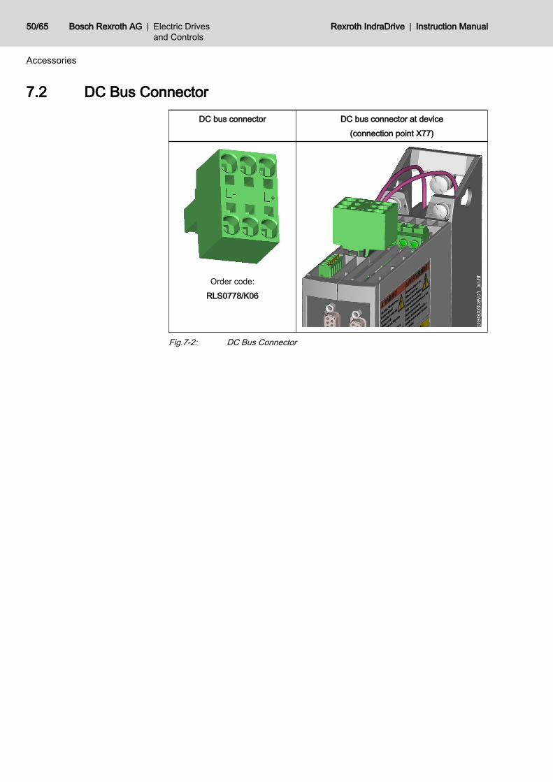
7.2 DC Bus ConnectorDC bus connector DC bus connector at device
(connection point X77)
Order code:RLS0778/K06
Fig.7-2: DC Bus Connector
50/65 Bosch Rexroth AG | Electric Drivesand Controls
Rexroth IndraDrive | Instruction Manual
Accessories

7.3 SUP-E01-MSM-BATTERYBOX"SUP-E01-MSM-BATTERYBOX" is a set of accessories used to operate MSMmotors with absolute value encoder and to backup the encoder data in casevoltage is switched off.
Scope of Supply
Fig.7-3: Battery BoxBattery box complete with● Battery, type: ERC6, 3,6 V; 1800 mA, lithium● Mounting screws: M6×30; Screw head: Torx and slot
Dimensions
Fig.7-4: DimensionsWeight 120 g
Mounting Mount the battery box as near as possible to the motor (maximumdistance approx. 2 m).
Fig.7-5: Boring Diagram for Battery Box● Mounting screws: M6×30● Tightening torque MA: 3 NmThe battery box "SUP-E01-MSM-BATTERYBOX" is supplied in ready-for-op‐eration status with battery.Wiring: MSM encoder plug-in connector → Battery box → HCS01
Instruction Manual | Rexroth IndraDrive Electric Drivesand Controls
| Bosch Rexroth AG 51/65
Accessories

7.4 SUP-E03-DKC*CS-BATTRY"SUP-E03-DKC*CS-BATTRY" contains accessories according to the enclosedproduct insert used to operate MSM motors with absolute value encoder. Usethese accessories when it is necessary to replace the battery of the battery box"SUP-E01-MSM-BATTERYBOX".
Battery Type: ERC6, 3,6 V; 1800 mA, lithiumResistance 10 ohm
Fig.7-6: SUP-E03-DKC*CS-BATTRYRefresh / Replacing the Battery Before using a new battery, you must always carry out the so-called "refresh"
procedure:
52/65 Bosch Rexroth AG | Electric Drivesand Controls
Rexroth IndraDrive | Instruction Manual
Accessories
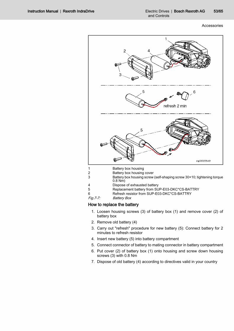
1 Battery box housing2 Battery box housing cover3 Battery box housing screw (self-shaping screw 30×10; tightening torque
0.8 Nm)4 Dispose of exhausted battery5 Replacement battery from SUP-E03-DKC*CS-BATTRY6 Refresh resistor from SUP-E03-DKC*CS-BATTRYFig.7-7: Battery Box
How to replace the battery1. Loosen housing screws (3) of battery box (1) and remove cover (2) of
battery box2. Remove old battery (4)3. Carry out "refresh" procedure for new battery (5): Connect battery for 2
minutes to refresh resistor4. Insert new battery (5) into battery compartment5. Connect connector of battery to mating connector in battery compartment6. Put cover (2) of battery box (1) onto housing and screw down housing
screws (3) with 0.8 Nm7. Dispose of old battery (4) according to directives valid in your country
Instruction Manual | Rexroth IndraDrive Electric Drivesand Controls
| Bosch Rexroth AG 53/65
Accessories

54/65 Bosch Rexroth AG | Electric Drivesand Controls
Rexroth IndraDrive | Instruction Manual

8 Service and SupportOur service helpdesk at out headquarters in Lohr, Germany, will assist you withall kinds of enquiries. Out of helpdesk hours please contact our German servicedepartment directly.
Helpdesk Service HotlineGermany
Service HotlineWorldwide
Time 1) Mo-Fr 7:00 am - 6:00 pm CET Mo-Fr 6:00 pm - 7:00 am CETSa-Su 0:00 am - 12:00 pm CET
Outwith Germany please con‐tact our sales/service office inyour area first.For hotline numbers refer to thesales office addresses on theInternet.
Phone +49 (0) 9352 40 50 60 +49 (0) 171 333 88 26or+49 (0) 172 660 04 06
Fax +49 (0) 9352 40 49 41 –
e-mail [email protected] –
Internet http://www.boschrexroth.comYou will also find additional notes regarding service, maintenance (e.g. delivery addresses) andtraining.
1) Central European Time (CET)
Preparing Information For quick and efficient help please have the following information ready:● detailed description of the fault and the circumstances● information on the type plate of the affected products, especially type co‐
des and serial numbers● your phone, fax numbers and e-mail address so we can contact you in
case of questions.
Instruction Manual | Rexroth IndraDrive Electric Drivesand Controls
| Bosch Rexroth AG 55/65
Service and Support

56/65 Bosch Rexroth AG | Electric Drivesand Controls
Rexroth IndraDrive | Instruction Manual

9 Environmental Protection and Disposal9.1 Environmental Protection
Production Processes The products are made with energy- and resource-optimized production pro‐cesses which allow re-using and recycling the resulting waste. We regularly tryto replace pollutant-loaded raw materials and supplies by more environment-friendly alternatives.
Prohibited Substances We guarantee that out products include no substances according to the chem‐icals-ban-decree. We furthermore declare that our products are free of mercury,asbestos, PCB and chlorinated hydrocarbons.
No Release of Hazardous Substan‐ces
Our products do not contain any hazardous substances which may be releasedin the case of appropriate use. Normally, our products will not have any negativinfluences on the environment.
Significant Components Basically, out products contain the following components:Electronic devices Motors∙ Steel ∙ Steel∙ Aluminum ∙ Aluminum∙ Copper ∙ Copper∙ Synthetic materials ∙ Brass∙ Electronic components and modules ∙ Magnetic materials ∙ Electronic components and modules
9.2 DisposalReturn of Products Our products can be returned to our premises free of charge for disposal. It is
a precondition, however, that the products are free of oil, grease or other dirt.Furthermore, the products returned for disposal must not contain any undueforeign material or foreign components.Send the products ”free domicile” to the following address: Bosch Rexroth AG Electric Drives and Controls Buergermeister-Dr.-Nebel-Strasse 2 97816 Lohr am Main, Germany
Packaging The packaging materials consist of cardboard, wood and polystyrene. Thesematerials can be recycled anywhere without any problem.For ecological reasons, please refrain from returning the empty packages tous.
Recycling Most of the products can be recycled due to their high content of metal. In orderto recycle the metal in the best possible way, the products must be disassem‐bled into individual modules.Metals contained in electric and electronic modules can also be recycled bymeans of special separation processes. The synthetic materials remaining afterthese processes can be thermally recycled.If the products contain batteries or accumulators, these have to be removedbefore recycling and disposed of.
Instruction Manual | Rexroth IndraDrive Electric Drivesand Controls
| Bosch Rexroth AG 57/65
Environmental Protection and Disposal

58/65 Bosch Rexroth AG | Electric Drivesand Controls
Rexroth IndraDrive | Instruction Manual

10 Appendix10.1 Discharging of Capacitors10.1.1 Discharging of DC Bus Capacitors
In the drive system Rexroth IndraDrive, capacitors are used in the DC bus asenergy stores. In drive controllers and particularly in supply units, such capac‐itors have already been integrated.Energy stores maintain their energy even when the supply voltage has beencut off and have to be discharged before somebody gets in contact with them.Discharging devices have been integrated in the components of the drive sys‐tem Rexroth IndraDrive; within the indicated discharging time, these devicesdischarge the voltage below the allowed 50 V.If additional capacitors (such as DC bus capacitor units) are connected, thesecapacitors, too, have to be discharged before somebody gets in contact withthem.Due to the operating principle, the discharging time is the longer● the bigger the energy store (the capacitance value)● the higher the voltage to which the energy store has been charged● the greater the resistance for discharging the capacitorsComponents of the drive system Rexroth IndraDrive have been dimensionedin such a way that after the supply voltage was cut off, the voltage value fallsbelow 50 V within a discharging time of a maximum of 30 minutes.To shorten the waiting time until voltage has fallen below 50 V, you can takethe following measures:● When using HMV01 supply units (exception: HMV01.1R-W0120):
Activate the function "ZKS" (ZKS = DC bus short circuit)● Use the discharging device described below
10.1.2 Discharging DeviceOperating Principle
A contactor is installed to switch a resistor to the terminals L+ and L- of the DCbus connection to discharge the capacitors. The contactor is activated via acontrol input which is supplied with appropriate control voltage.
R Discharging resistorK Contactor contactFig.10-1: Operating Principle of Discharging Device
Instruction Manual | Rexroth IndraDrive Electric Drivesand Controls
| Bosch Rexroth AG 59/65
Appendix

DimensioningThe individual components have to be sufficiently dimensioned:● Value of the discharging resistor: 1000 ohm and at least 1000 W● The discharging resistor and the contactor contact have to withstand the
loads of practical operation (for example in the case of frequent use of thedischarging device of the occurring continuous power).
● The contactor contact has to withstand the occurring direct voltage of aminimum of 1000 V.
● The contactor contact has to withstand the occurring discharge currentaccording to the resistance value that is used, i.e. 1 A with 1000 ohm.
Installation
WARNING
Lethal electric shock caused by live parts with more than 50 V!Before working on live parts: De-energize the installation and secure the powerswitch against unintentional or unauthorized re-energization.Wait at least 30 minutes after switching off the supply voltages to allow dis‐charging.Check whether voltages have fallen below 50 V before touching live parts!
CAUTION
Risk of damage by intense heat!During the discharging process, the discharging resistor generates intenseheat. Therefore, place the discharging resistor as far as possible from heat-sensitive components.
How to install the discharging device1. Preferably install discharging device before switching on supply voltage
for the first time.If you install discharging device after having switched on supply voltagefor the first time, wait 30 minutes to allow discharging. Check whethervoltage has fallen below 50 V before touching live parts!
2. Place discharging resistor as far as possible from heat-sensitive compo‐nents.
ActivationObserve the following order for activating the discharging device:1. De-energize installation and secure power switch against unintentional or
unauthorized re-energization.2. Activate discharging device.
60/65 Bosch Rexroth AG | Electric Drivesand Controls
Rexroth IndraDrive | Instruction Manual
Appendix
IndexSymbols24V supply
Connection point .......................................... 27
AAccessories
Battery .......................................................... 52DC bus connector ........................................ 50HAS09 .......................................................... 49Mounting and connection accessories(HAS09) ....................................................... 49Replacement battery .................................... 52SUP-E01-MSM-BATTERYBOX ................... 51SUP-E03-DKC*CS-BATTRY ........................ 52X77, DC bus connector ................................ 50
Ambient conditions.............................................. 13
BBattery
Refresh ......................................................... 52SUP-E03-DKC*CS-BATTRY ........................ 52
Braking resistorExternal, connection ..................................... 26Integrated, connection .................................. 26Parameterization .......................................... 27
CCables
Documentation ............................................. 15Shield connection ......................................... 31Strain relief ................................................... 31
CapacitorsDischarging .................................................. 59
Connection24V supply (X13) .......................................... 27Braking resistor (X9) .................................... 26Control voltage (X13) ................................... 27DC bus (X77) ............................................... 28Equipment grounding conductor .................. 20Ground ......................................................... 32Mains (X3) .................................................... 21Motor (X5) .................................................... 23Motor holding brake (X6) .............................. 25Motor temperature monitoring (X6) .............. 25Shield ........................................................... 31
Connection diagram............................................ 19Connection points............................................... 18Contained substances
see "Significant components" ....................... 57Control cabinet
Area A, interference-free .............................. 43Area B, interference-susceptible .................. 45Area C, strongly interference-susceptible .... 45Avoiding moisture condensation .................. 37
C...Control cabinet
Cooling unit .................................................. 36Interference areas ........................................ 42Multiple-line arrangement of drive control‐lers ............................................................... 35
Control voltageConnection point X13 ................................... 27Loop-through contacts (X13) ........................ 27
Cooling unitArrangement ................................................ 36
DDC bus
Connection point X77 ................................... 28Connector, accessories ................................ 50
DC bus capacitorsDischarging .................................................. 59
Dimensions......................................................... 13Discharging
Of DC bus capacitors ................................... 59Discharging device.............................................. 59Distances............................................................ 14Documentation
Cables .......................................................... 15Drive systems ............................................... 15Firmware ...................................................... 15Motors .......................................................... 15Overview ...................................................... 15Reference documentations .......................... 15System components ..................................... 15
Drive controllersMultiple-line arrangement ............................. 35
EEMC
Measures for design and installation ............ 39Equipment grounding conductor
Connection ................................................... 20
FFirmware
Documentation ............................................. 15
GGround
Connection ................................................... 32Ground connection.............................................. 32Ground connections............................................ 46
Instruction Manual | Rexroth IndraDrive Electric Drivesand Controls
| Bosch Rexroth AG 61/65
Index

HHAS09
Accessories (for mounting and installation) . 49Hazardous substances....................................... 57HCS01
Mounting in the control cabinet .................... 34Scope of supply ............................................ 12Technical data .............................................. 13Type code .................................................... 11Type plate .................................................... 12
IIdentification........................................................ 11Installation........................................................... 32
EMC measures ............................................ 39General information ...................................... 32Ground connections ..................................... 46Signal lines ................................................... 47
Instructions for use.............................................. 17
LL+, L-
DC bus ......................................................... 28
MMains connection
X3 ................................................................. 21Mains filter
Motor blower ................................................ 44Other loads ................................................... 44
Measures of radio interference suppressionFor relays, contactors, switches, chokes,inductive loads ............................................. 48
Moisture condensationAvoiding ....................................................... 37
MotorConnection (X5) ........................................... 23Connection motor holding brake (X6) .......... 25Connection motor temperature monitoring(X6) .............................................................. 25Documentation ............................................. 15Motor holding brake ..................................... 25Motor output (X5) ......................................... 23Motor temperature monitoring ...................... 25
Motor blowerMains filter .................................................... 44
Motor cableShield connection ......................................... 32
MountingHCS01 in the control cabinet ....................... 34
Multiple-line arrangement of drive controllers..... 35
OOperating conditions........................................... 13Overcurrent protection........................................ 17
PPackaging........................................................... 57Power consumption............................................ 13Production processes......................................... 57Prohibited substances......................................... 57Project planning manuals
Reference ..................................................... 15
RRatings................................................................ 13Reference documentations................................. 15Refresh
Battery (SUP-E03-DKC*CS-BATTRY) ......... 52Return of products.............................................. 57
SSafety instructions................................................. 5Scope of supply
HCS01 .......................................................... 12Service Hotline.................................................... 55Shield
Connection ................................................... 31Motor cable .................................................. 32
Signal linesInstallation .................................................... 47
Significant components....................................... 57Strain relief
Cables .......................................................... 31SUP-E01-MSM-BATTERYBOX.......................... 51SUP-E03-DKC*CS-BATTRY.............................. 52Support
see Service Hotline ...................................... 55
TTechnical data..................................................... 13Type code
HCS01 .......................................................... 11Type plate
HCS01 .......................................................... 12Type plates......................................................... 12
UUL ratings............................................................ 13Use
Instructions ................................................... 17
VVoltage load capacity.......................................... 13
WWiring diagram.................................................... 18
62/65 Bosch Rexroth AG | Electric Drivesand Controls
Rexroth IndraDrive | Instruction Manual
Index
H

XX13
Control voltage (24 V) .................................. 27X3
Mains connection ......................................... 21X5
Motor output ................................................. 23X6
Motor temperature monitoring and motorholding brake ................................................ 25
XX77
DC bus connection ....................................... 28DC bus connector ........................................ 50
X9Braking resistor ............................................ 26
Instruction Manual | Rexroth IndraDrive Electric Drivesand Controls
| Bosch Rexroth AG 63/65
Index
X

64/65 Bosch Rexroth AG | Electric Drivesand Controls
Rexroth IndraDrive | Instruction Manual

Notes
Instruction Manual | Rexroth IndraDrive Electric Drivesand Controls
| Bosch Rexroth AG 65/65

Printed in GermanyDOK-INDRV*-HCS01*UL***-IB01-EN-PR911325518
Bosch Rexroth AGElectric Drives and ControlsP.O. Box 13 5797803 Lohr, GermanyBgm.-Dr.-Nebel-Str. 297816 Lohr, GermanyTel. +49 (0)93 52-40-0Fax +49 (0)93 52-48 85www.boschrexroth.com