ELECTRIC CURRENT AND CIRCUIT ANALYSIS I ... - … · ELECTRIC CURRENT AND CIRCUIT ANALYSIS ... To...
22
1 ELECTRIC CURRENT AND CIRCUIT ANALYSIS I. WORK IN ELECTRIC FIELDS How does charge move? Remember when we talked about ELECTRIC FIELDS in STATIC ELECTRICITY? Like GRAVITY, an ELECTRIC FIELD is one of the forces that act through a distance. If both the source charge and test charge are +, we know the test charge will naturally move away PE of the test charge DECREASES To get the test charge to move toward the source charge, against the electric field, external WORK is required PE of the test charge INCREASES Q q F electr source charge test charge Q q F electr source charge test charge
Transcript of ELECTRIC CURRENT AND CIRCUIT ANALYSIS I ... - … · ELECTRIC CURRENT AND CIRCUIT ANALYSIS ... To...

1
ELECTRIC CURRENT AND CIRCUIT ANALYSIS
I. WORK IN ELECTRIC FIELDS
How does charge move? Remember when we talked about ELECTRIC FIELDS in STATIC ELECTRICITY?
Like GRAVITY, an ELECTRIC FIELD is one of the forces that act through a distance.
If both the source charge and test charge are +, we know the test charge will naturally move away
PE of the test charge DECREASES
To get the test charge to move toward the source charge, against the electric field, external WORK is required
PE of the test charge INCREASES
Q q
Felectr
sourcechargetestcharge
Q q
Felectr
sourcechargetestcharge

2
electric fields, continued
that’s an awful lot like how gravitational PE works…
If I do work on an object to lift it, the PE of the object INCREASES.
+ +
Felectr
sourcechargetestcharge
PE of test charge increases with decreasing distance apart
PE of object increases with increasing height
Fgrav
work work
‐ +
Felectr
sourcechargetestcharge
no work
work
When the charges are OPPOSITE, it requires external work to move them apart, against the electric field.
The PE of the test charge DECREASES with decreasing distance apart.

3
II. ELECTRIC POTENTIAL ENERGY and ELECTRIC POTENTIAL
Let’s think about the last diagram a little more…
‐ +
Felectr
sourcechargetestcharge
no work
work
When the charges are OPPOSITE, it requires external work to move them apart, against the electric field.
The PE of the test charge DECREASES with decreasing distance apart.
AS UNLIKE CHARGES ARE SEPARATED, THE PE INCREASES.
BUT, IF THE TEST CHARGE IS ALLOWED TO MOVE (+ FLOWING TOWARD NEGATIVE) THE PE DECREASES UNTIL PE = 0

4
Electric potential energy, continued
Electric potential energy depends on the MAGNITUDE of the charge. The bigger the charge, the more work that is needed to “push” it and the larger the PE.
++++++++
+
Felectr
sourcecharge testcharges
2+
+
2+
r
work is done to move the charges from right to left
It will take 2x the work to move the 2+ charge compared to the + charge The 2+ charge particle will have 2x (twice) the PE of the + charge particle.

5
electric potential energy, continued
++++++++
+
Felectr
sourcecharge testcharges
2+
+
2+
r
BUT …THE ELECTRIC POTENTIAL IS THE SAME FOR BOTH PARTICLES.
VE =PEQ
The electric potential, VE, is the ratio of the PE to charge of a particle. We just said, if Q goes up, PE goes up proportionately.
The electric potential is the same for both our + and 2+ charged particles because THEY ARE THE SAME DISTANCE FROM THE SOURCE APPLYING THE FORCE.
PE increases distance from source changes VE

6
This idea of an ELECTRIC POTENTIAL is important in understanding how current flows in a circuit.
Felectr
Here’s a simple circuit.
A battery powering a light bulb
The electric field is, as always, pointed from + to –
As before, we would expect no external work for a + charge to flow from the + end of the battery to the – end. A + charge moving the other way would require work.
On the battery, the + terminal is the HIGH ELECTRIC POTENTIAL END the – terminal is the LOW POTENTIAL END
Like water running downhill, electric current will flow naturally from a HIGH VE to a LOW VE
charge does work to light the bulb, lowering the PE of the charge

7
III. ELECTRIC POTENTIAL DIFFERENCE
The chemical energy inside a battery provide the energy needed to do the work to push charge from a low potential to a high potential.
Even though we recognize current as being negative, it is traditional to teach that the + terminal of the battery is the high potential end. Therefore, we’ll say the role of the chemical reaction in the battery to maintain an ELECTRIC POTENTIAL DIFFERENCE by doing work on the + charges by pushing them to the + terminal.
This keeps the current flowing in a circuit. When there is no charge flow in and out of the battery, the chemical reaction doesn’t go. That’s basically how a battery is able to store power.
Think of the battery as a CHARGE PUMP. When a + charge returns from its journey around the circuit, it has PE = 0. The battery “pumps” it back up to high PE and high potential + terminal.
A. The battery
+1.5 V
0 V
When connected, the + terminal of a battery is at the voltage rating of the battery but the – terminal is 0 volts

8
B. Voltage difference
There is a DIFFERENCE in ELETRIC POTENTIAL between the + and – terminals of a battery. This is like the difference in potential of water at the top of a fall and the bottom. The water falls naturally from the top (high potential) to the bottom (low potential) and only work (like a pump) can get the water back up to high potential.
A circuit with a battery is like the waterfall (with a water pump at the bottom).
Current flows from high to low potential and must be pumped back to high potential for the circuit to work.
The difference in potential between two points in a circuit is
ΔV =ΔPEQ
V is the voltage and the units are volts (V). THINK OF VOLTAGE AS A MEASURE OF ELECTRIC PRESSURE (the “push” a charge gets in the circuit)
change in volts is a change in potential energy per unit charge
9
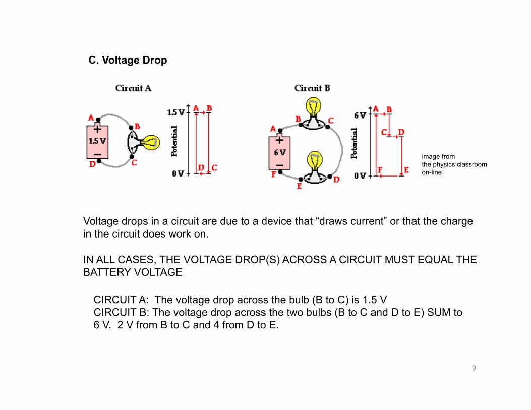
C. Voltage Drop
image from the physics classroom on-line
Voltage drops in a circuit are due to a device that “draws current” or that the charge in the circuit does work on.
IN ALL CASES, THE VOLTAGE DROP(S) ACROSS A CIRCUIT MUST EQUAL THE BATTERY VOLTAGE
CIRCUIT A: The voltage drop across the bulb (B to C) is 1.5 V CIRCUIT B: The voltage drop across the two bulbs (B to C and D to E) SUM to 6 V. 2 V from B to C and 4 from D to E.

10
IV. WHAT IS A CIRCUIT?
We used circuits as examples in these notes without saying much about what it actually is. Intuition tells you a circuit must be a closed path for current to flow.
IF YOU HAVE ELECTRIC POTENTIAL BETWEEN TWO OBJECTS, YOU DO NOT HAVE A CIRCUIT UNTIL THERE IS A CONDUCTING PATH BETWEEN THE TWO.
To have a circuit, “electric pressure” must be present. There must be a HIGH POTENTIAL end and a LOW POTENTIAL end.
To have a circuit, the power supply must be able to move charge from a low potential to a high potential.
A circuit with a “break” in it will not conduct.
A circuit that does not connect the high potential to the low potential will not work.
good circuit bulb connected through a path from high to low potential
bad circuit light bulb is not in the path

11
V. WHAT IS CURRENT?
Current is the RATE at which charge passes a given point in a circuit.
I =Qt
I is the current.
The SI unit for current is amp, A
A is coulomb/s
Current direction is usually defined by the direction that a POSITIVE charge would move. Thus, in a circuit, we say that the current moves from the + terminal to the – terminal.
electrons flow this way
conventional current flows this way

12
WHAT IS DRIFT SPEED?
Current actually MOVES SLOWLY through the circuit. A circuit responds quickly because of HOW MANY charge carriers (electrons) there are in a copper wire. They are spread over the whole length and cross section of a wire so the current moves forward IMMEDIATELY after it is energized. THE SIGNAL TO MOVE (ELECTRIC FIELD) GOES THROUGH THE CIRCUIT AT NEARLY THE SPEED OF LIGHT.
DRIFT SPEED is the rate at which an electron moves in the wire. A typical drift speed is about 1 meter per hour. VERY SLOW. Though an individual electron moves very fast, its direction in the wire is almost random with a net forward direction toward the high potential end of the circuit.
TO GET A CIRCUIT TO WORK, THE ELECTRONS DON’T HAVE TO GO FROM THE BATTERY TO THE LIGHT BULB (OR WHATEVER). THE ELECTRONS ARE ALREADY THERE, IN THE WIRE THAT CREATES THE CIRCUIT PATH.

13
VI. POWER IN THE CIRCUIT
POWER is the rate at which electrical energy is used by the LOAD (like a bulb) in the circuit. It is the amount of work the charge does on the load per unit time.
As before, the unit is the WATT.
P =ΔEt
ΔE = QΔV
P =QΔVt
I =Qt
P = IΔVPower is the product of the current and the electric potential difference (voltage)

14
VII. RESISTANCE
RESISTANCE IS THE HINDERANCE OF THE FLOW OF CHARGE.
Every time a LOAD is added to a circuit, the ELECTRIC POTENTIAL of the circuit is reduced. A LOAD creates a point of resistance in the circuit.
Even the wires in the circuit create resistance. long wire, more resistance thin wire (small cross sectional area), more resistance
The RESISTIVITY is a measure of resistance. The units are ohm-meters, Ωm. The bigger the value for a material, the higher the resistance Different materials have different electrical resistance. Metals (conductors) have low resistivity values, materials like glass and rubber have high resistivity values (insulators).
for a wire, the resistance can be calculated as: R = ρ LA
ρ is the resistivity value L is the length in meters A is the cross sectional area in m2

15
VIII. BUILDING AND ANALYZING A CIRCUIT
A circuit needs, at minimum, a power supply and a wire to connect the high potential to the low potential.
That’s a pretty worthless circuit though. A resistor or load of some sort is added between the high and low potentials to get the circuit to do something useful (work on the load).
a simple circuit might look like this:
each R is a resistor.
A. CIRCUIT SYMBOLS

16
B. OHM’S LAW
Ohm’s Law is used to predict the current in a circuit across a load.
In a circuit, the ratio of the TOTAL VOLTAGE and the TOTAL RESISTANCE gives the CURRENT
I =ΔVR
The more load placed on a circuit, the lower the current amperage
unit for I is the AMPERE, A
If each resistor is 3 Ω and the battery provides a 3 V potential difference, then the current in this circuit is
I =3V
(3+ 3+ 3)Ω= 0.33A

17
Ohm’s Law, continued
From Ohm’s Law, we can write equations for circuit POWER:
P = IΔVΔV = IRP = I 2Rand
I =ΔVR
P =ΔV
2
R
Ohm’s Law
Ohm’s Law
18
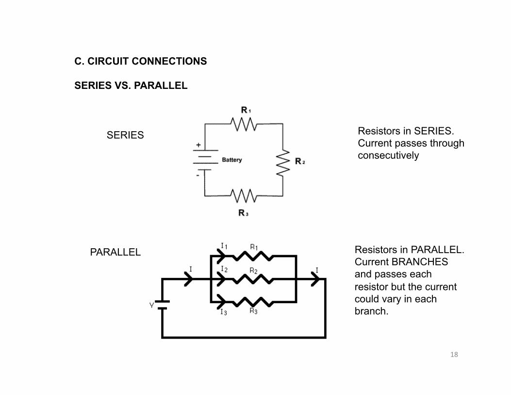
C. CIRCUIT CONNECTIONS
SERIES VS. PARALLEL
SERIES
PARALLEL
Resistors in SERIES. Current passes through consecutively
Resistors in PARALLEL. Current BRANCHES and passes each resistor but the current could vary in each branch.

19
D. ANALYZING A SERIES CIRCUIT
If one of the resistors in a series circuit “breaks” (which opens the circuit path), then the other resistors will not receive the current.
In a series circuit, the total voltage is equal to the sum of the voltage drops at each resistor The equivalent resistance for the circuit is the sum of the resistance values for each resistor
Look at the current equation above. For a series circuit, the current is the same everywhere. Resistors don’t “eat up” current. Current is the RATE of charge flow and that is the same everywhere in the circuit.
ΔVbatteryIbattery
ΔV3 = IR3
ΔV2 = IR2
ΔV1 = IR1
ΔVbattery = ΔV1 + ΔV2 + ΔV3
Req = R1 + R2 + R3
Ibattery = I1 = I2 = I3 =ΔVbatteryReq

20
E. ANALYZING A PARALLEL CIRCUIT
Because a parallel circuit branches, if one of the resistors “breaks”, the other resistors will still receive current. The circuit path will still be intact.
The CURRENT at the branch will equal the current after the branches re-join.
The CURRENT through each branch may be different (depends on resistance) but the sum from each branch must equal the TOTAL current.
In parallel circuits, adding another resistance branch LOWERS the resistance of the circuit and INCREASES the current
In parallel circuits, the VOLTAGE DROP across each resistor is the same.

21
parallel circuits, continued
ΔVbattery = ΔV1 = ΔV2 = ΔV3
Itotal = I1 + I2 + I3
Req =1R1
+1R2
+1R3
⎛⎝⎜
⎞⎠⎟
−1
R1 =ΔVbatteryI1
R2 =ΔVbatteryI2
R3 =ΔVbatteryI3

22
F. Combining circuits (reducing to simpler circuit)
This circuit, which is two parallel resistor arrangements in series, can be re-drawn as the circuit on the right. Each pair of parallel resistors is combined (mathematically) to give 1 resistor for each pair.