Electric Circuits II - Philadelphia University...Electric Circuits II AC Circuit Power Analysis 1...
27
Electric Circuits II AC Circuit Power Analysis 1 Dr. Firas Obeidat
Transcript of Electric Circuits II - Philadelphia University...Electric Circuits II AC Circuit Power Analysis 1...
Electric Circuits II AC Circuit Power Analysis
1
Dr. Firas Obeidat

Dr. Firas Obeidat – Philadelphia University
2
1
• Conservation of AC power
1 • Power Triangle
1 • Power Factor Correction
Table of Contents

Dr. Firas Obeidat – Philadelphia University
3
Conservation of AC Power
The principle of conservation of power applies to ac circuits can be explained
by considering AC parallel circuit and AC series circuit.
AC parallel circuit
two load impedances Z1 and Z2 are connected in
parallel across an ac source V. KCL gives
The complex power supplied by the source is
𝐒 = 𝐕𝐫𝐦𝐬𝐈𝐫𝐦𝐬∗ = 𝐕𝐫𝐦𝐬(𝐈𝟏𝐫𝐦𝐬
∗+𝐈𝟐𝐫𝐦𝐬∗) = 𝐕𝐫𝐦𝐬𝐈𝟏𝐫𝐦𝐬
∗+𝐕𝐫𝐦𝐬𝐈𝟐𝐫𝐦𝐬∗= 𝐒𝟏 + 𝐒𝟐
Where S1 and S2 denote the complex powers delivered to loads Z1 and Z2.
The complex, real, and reactive powers of the sources equal the respective sums
of the complex, real, and reactive powers of the individual loads.
𝐈𝐫𝐦𝐬 = 𝐈𝟏𝐫𝐦𝐬 +𝐈𝟐𝐫𝐦𝐬

Dr. Firas Obeidat – Philadelphia University
4
Conservation of AC Power
AC series circuit
If the loads are connected in series with the voltage
source, KVL yields
The complex power supplied by the source is
𝐒 = 𝐕𝐫𝐦𝐬𝐈𝐫𝐦𝐬∗ = (𝐕𝟏𝐫𝐦𝐬+𝐕𝟐𝐫𝐦𝐬)𝐈𝐫𝐦𝐬
∗= 𝐕𝟏𝐫𝐦𝐬𝐈𝐫𝐦𝐬∗+𝐕𝟐𝐫𝐦𝐬𝐈𝐫𝐦𝐬
∗= 𝐒𝟏 + 𝐒𝟐
Where S1 and S2 denote the complex powers delivered to loads Z1 and Z2.
𝐕𝐫𝐦𝐬 = 𝐕𝟏𝐫𝐦𝐬 +𝐕𝟐𝐫𝐦𝐬
From the above discussion, it can be concluded that whether the loads are
connected in series or in parallel (or in general), the total power supplied by the
source equals the total power delivered to the load. Thus, in general, for a source
connected to N loads,

Dr. Firas Obeidat – Philadelphia University
5
Power Triangle
The three quantities average power, apparent power, and reactive power can be
related in the vector domain by
𝐒 = 𝐕𝐫𝐦𝐬𝐈𝐫𝐦𝐬∗=P+jQ
𝐰𝐡𝐞𝐫𝐞 𝐏 = 𝑃∠0, 𝐐𝐋 = 𝑗𝑄𝐿= 𝑄𝐿∠90, 𝐐𝐂 = −𝑗𝑄𝐶= 𝑄𝐶∠ − 90
When solving problems involving power, P
values can be added to get PT, and Q values
to get QT (where Q is positive for inductive
elements and negative for capacitive).
For an inductive load, the phasor power S is
𝐒=P+j𝑸𝑳
For an capacitive load, the phasor power S is
𝐒=P-j𝑸𝑪 (a)
(b)
As in figure (a)
As in figure (b)
Dr. Firas Obeidat – Philadelphia University
6
Power Triangle
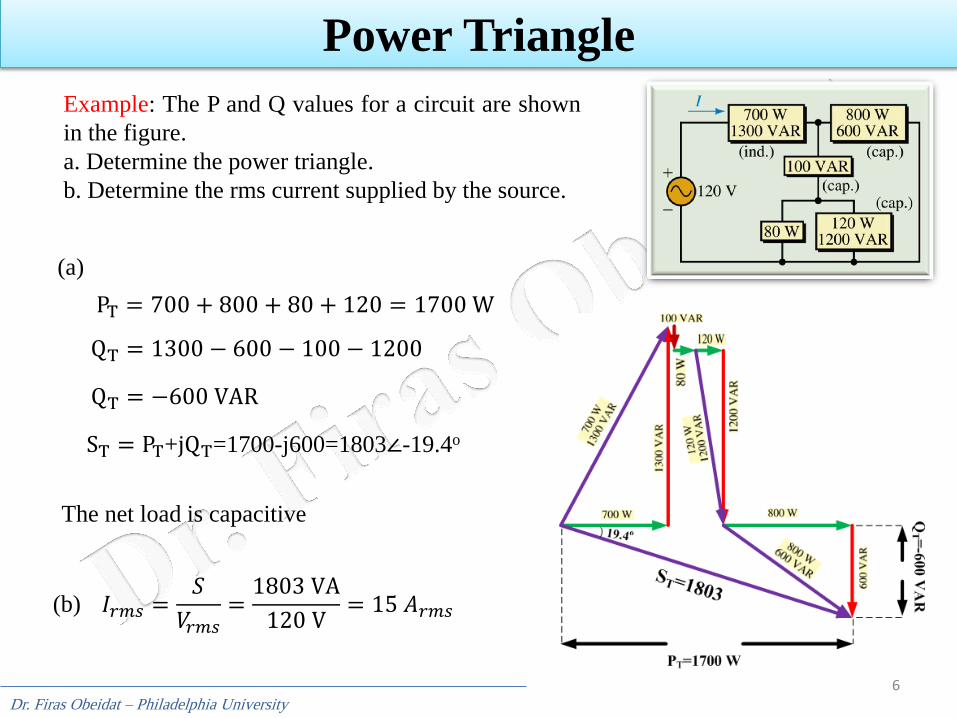
Example: The P and Q values for a circuit are shown
in the figure.
a. Determine the power triangle.
b. Determine the rms current supplied by the source.
PT = 700 + 800 + 80 + 120 = 1700 W
QT = 1300 − 600 − 100 − 1200
QT = −600 VAR
ST = PT+jQT=1700-j600=1803∠-19.4o
(a)
(b) 𝐼𝑟𝑚𝑠 =𝑆
𝑉𝑟𝑚𝑠=
1803 VA
120 V= 15 𝐴𝑟𝑚𝑠
The net load is capacitive
Dr. Firas Obeidat – Philadelphia University
7
Power Triangle
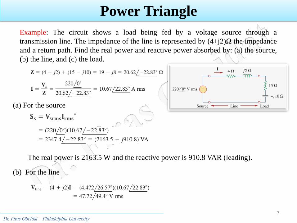
Example: The circuit shows a load being fed by a voltage source through a
transmission line. The impedance of the line is represented by (4+j2)Ω the impedance
and a return path. Find the real power and reactive power absorbed by: (a) the source,
(b) the line, and (c) the load.
𝐒𝐬 = 𝐕𝐬𝐫𝐦𝐬𝐈𝐫𝐦𝐬∗
The real power is 2163.5 W and the reactive power is 910.8 VAR (leading).
(a) For the source
(b) For the line
Dr. Firas Obeidat – Philadelphia University
8
Power Triangle
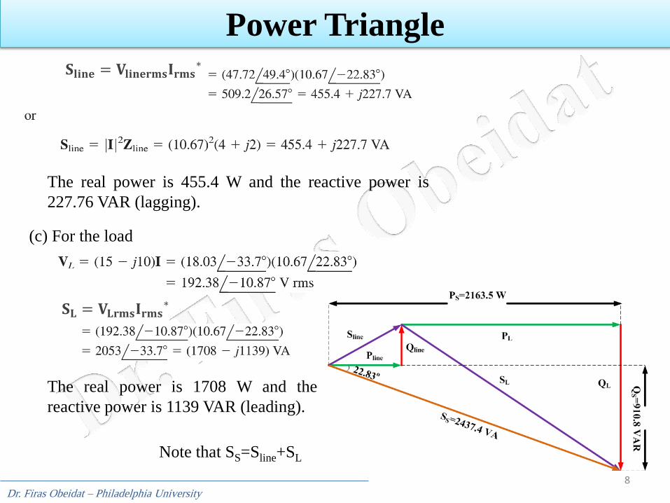
The real power is 455.4 W and the reactive power is
227.76 VAR (lagging).
(c) For the load
𝐒𝐥𝐢𝐧𝐞 = 𝐕𝐥𝐢𝐧𝐞𝐫𝐦𝐬𝐈𝐫𝐦𝐬∗
𝐒𝐋 = 𝐕𝐋𝐫𝐦𝐬𝐈𝐫𝐦𝐬∗
The real power is 1708 W and the
reactive power is 1139 VAR (leading).
Note that SS=Sline+SL

Dr. Firas Obeidat – Philadelphia University
9
Power Triangle
Example: A generator (its voltage in rms) supplies power to an electric heater, an
inductive element, and a capacitor as in the figure.
a. Find P and Q for each load.
b. Find total active and reactive power supplied by the generator.
c. Draw the power triangle for the combined loads and determine total apparent
power.
d. Find the current supplied by the generator.
(a) The components of power are as follows:
(b)
Dr. Firas Obeidat – Philadelphia University
10
Power Triangle
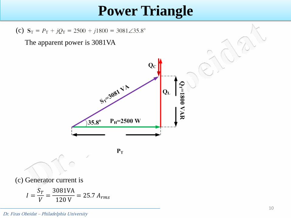
(c)
The apparent power is 3081VA
(c) Generator current is
𝐼 =𝑆𝑇
𝑉=
3081VA
120 V= 25.7 𝐴𝑟𝑚𝑠
Dr. Firas Obeidat – Philadelphia University
11
Power Triangle
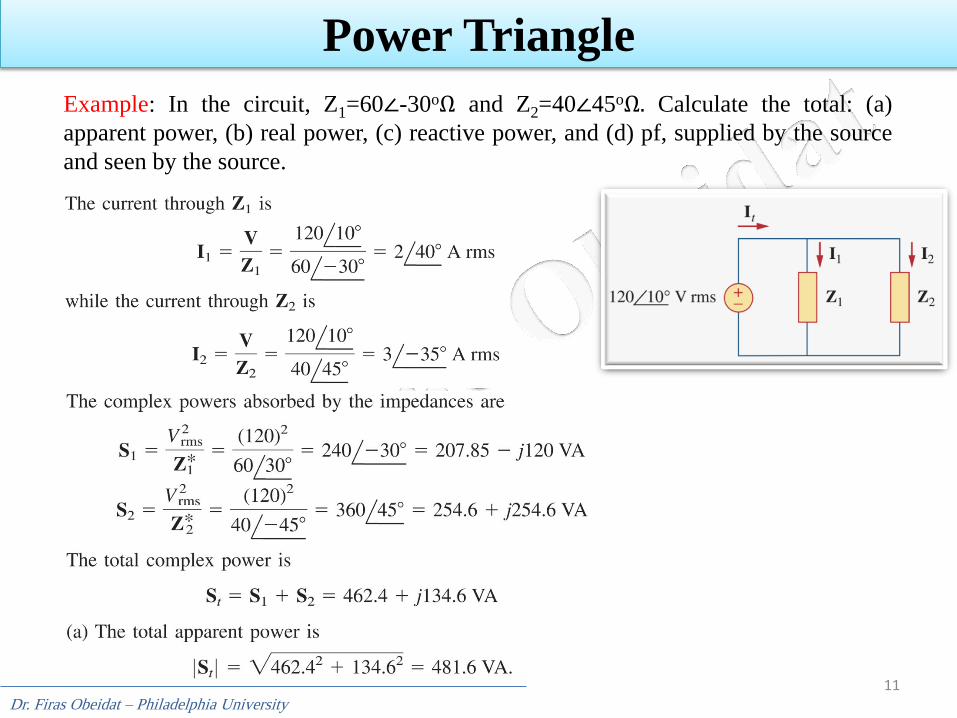
Example: In the circuit, Z1=60∠-30oΩ and Z2=40∠45oΩ. Calculate the total: (a)
apparent power, (b) real power, (c) reactive power, and (d) pf, supplied by the source
and seen by the source.
Dr. Firas Obeidat – Philadelphia University
12
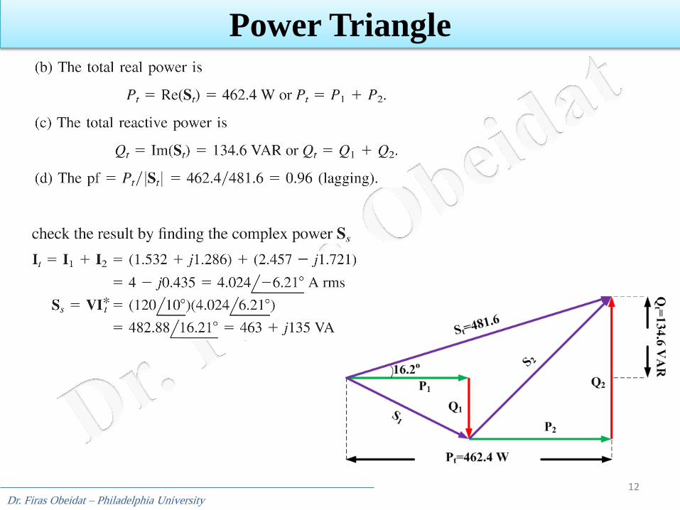
Power Triangle
Dr. Firas Obeidat – Philadelphia University
13
Power Triangle
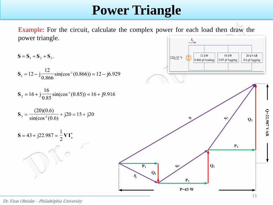
Example: For the circuit, calculate the complex power for each load then draw the
power triangle.
Dr. Firas Obeidat – Philadelphia University
14
Power Triangle
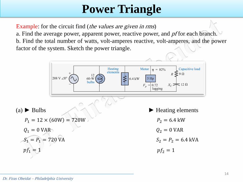
Example: for the circuit find (the values are given in rms)
a. Find the average power, apparent power, reactive power, and pf for each branch.
b. Find the total number of watts, volt-amperes reactive, volt-amperes, and the power
factor of the system. Sketch the power triangle.
𝑃1 = 12 × 60W = 720W
𝑝𝑓1 = 1
𝑄1 = 0 VAR
(a) ► Bulbs
𝑆1 = 𝑃1 = 720 VA
𝑃2 = 6.4 kW
𝑄2 = 0 VAR
► Heating elements
𝑆2 = 𝑃2 = 6.4 kVA
𝑝𝑓2 = 1
Dr. Firas Obeidat – Philadelphia University
15
Power Triangle
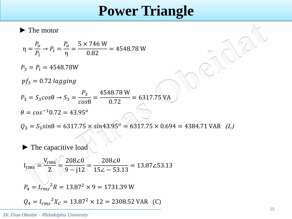
𝑝𝑓3 = 0.72 𝑙𝑎𝑔𝑔𝑖𝑛𝑔
► The motor
η =𝑃𝑜
𝑃𝑖→ 𝑃𝑖 =
𝑃𝑜
η=
5 × 746 W
0.82= 4548.78 W
𝑃3 = 𝑃𝑖 = 4548.78W
𝑃3 = 𝑆3𝑐𝑜𝑠θ → 𝑆3 =𝑃3
𝑐𝑜𝑠θ=
4548.78 W
0.72= 6317.75 VA
𝜃 = 𝑐𝑜𝑠−10.72 = 43.95𝑜
𝑄3 = 𝑆3𝑠𝑖𝑛θ = 6317.75 × 𝑠𝑖𝑛43.95𝑜 = 6317.75 × 0.694 = 4384.71 VAR (L)
► The capacitive load
Irms =Vrms
Z=
208∠0
9 − j12=
208∠0
15∠ − 53.13= 13.87∠53.13
𝑃4 = 𝐼𝑟𝑚𝑠2𝑅 = 13.872 × 9 = 1731.39 W
𝑄4 = 𝐼𝑟𝑚𝑠2𝑋𝐶 = 13.872 × 12 = 2308.52 VAR (C)
Dr. Firas Obeidat – Philadelphia University
16
Power Triangle
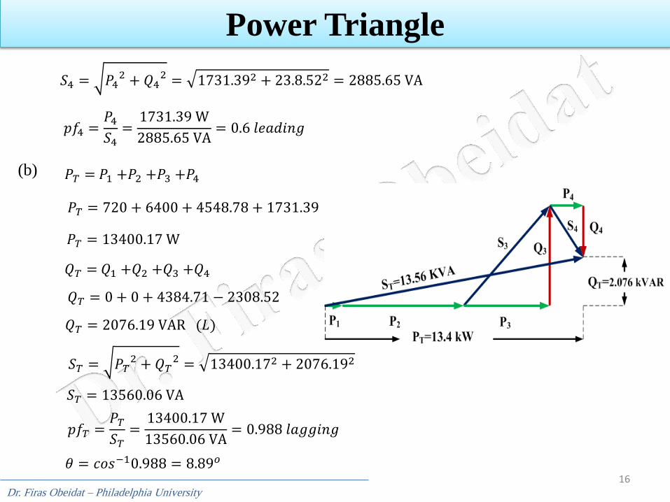
𝑆4 = 𝑃42 + 𝑄4
2 = 1731.392 + 23.8.522 = 2885.65 VA
𝑝𝑓4 =𝑃4
𝑆4=
1731.39 W
2885.65 VA= 0.6 𝑙𝑒𝑎𝑑𝑖𝑛𝑔
(b) 𝑃𝑇 = 𝑃1 +𝑃2 +𝑃3 +𝑃4
𝑃𝑇 = 720 + 6400 + 4548.78 + 1731.39
𝑃𝑇 = 13400.17 W
𝑄𝑇 = 𝑄1 +𝑄2 +𝑄3 +𝑄4
𝑄𝑇 = 0 + 0 + 4384.71 − 2308.52
𝑄𝑇 = 2076.19 VAR (𝐿)
𝑆𝑇 = 𝑃𝑇2 + 𝑄𝑇
2 = 13400.172 + 2076.192
𝑆𝑇 = 13560.06 VA
𝑝𝑓𝑇 =𝑃𝑇
𝑆𝑇=
13400.17 W
13560.06 VA= 0.988 𝑙𝑎𝑔𝑔𝑖𝑛𝑔
𝜃 = 𝑐𝑜𝑠−10.988 = 8.89𝑜
Dr. Firas Obeidat – Philadelphia University
17
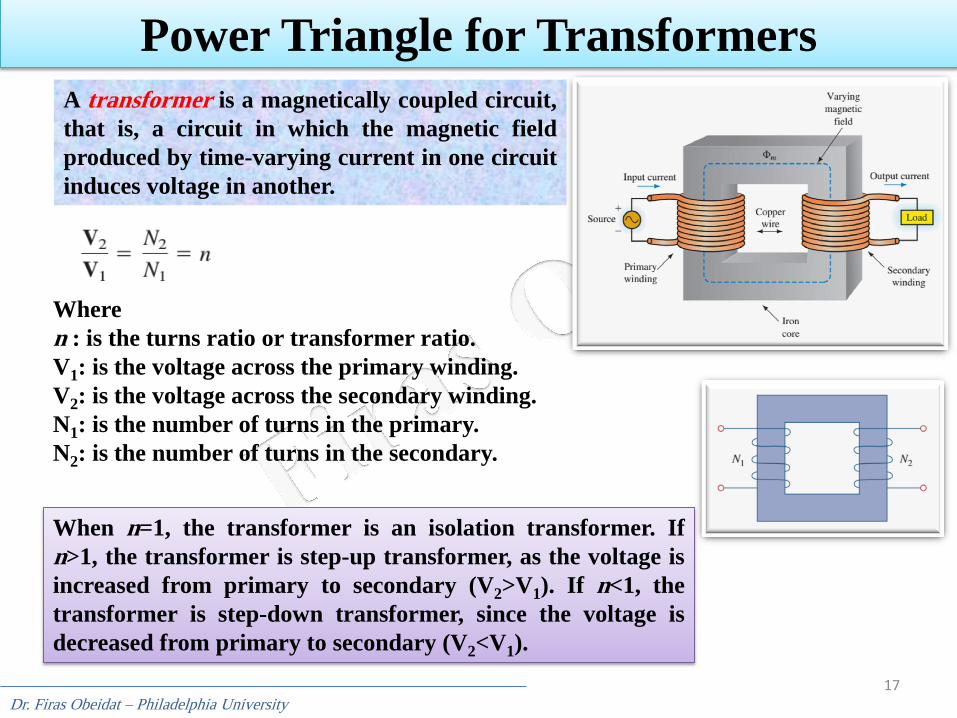
Power Triangle for Transformers
A transformer is a magnetically coupled circuit,
that is, a circuit in which the magnetic field
produced by time-varying current in one circuit
induces voltage in another.
Where
n : is the turns ratio or transformer ratio.
V1: is the voltage across the primary winding.
V2: is the voltage across the secondary winding.
N1: is the number of turns in the primary.
N2: is the number of turns in the secondary.
When n=1, the transformer is an isolation transformer. If
n>1, the transformer is step-up transformer, as the voltage is
increased from primary to secondary (V2>V1). If n<1, the
transformer is step-down transformer, since the voltage is
decreased from primary to secondary (V2<V1).
Dr. Firas Obeidat – Philadelphia University
18
Power Triangle for Transformers
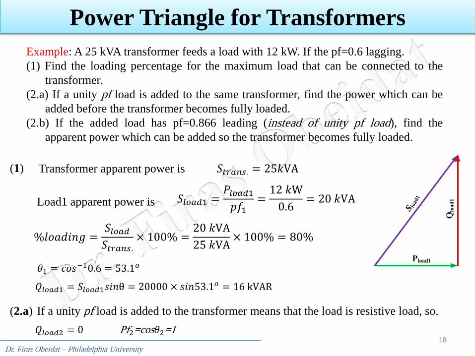
Example: A 25 kVA transformer feeds a load with 12 kW. If the pf=0.6 lagging.
(1) Find the loading percentage for the maximum load that can be connected to the
transformer.
(2.a) If a unity pf load is added to the same transformer, find the power which can be
added before the transformer becomes fully loaded.
(2.b) If the added load has pf=0.866 leading (instead of unity pf load), find the
apparent power which can be added so the transformer becomes fully loaded.
𝑆𝑡𝑟𝑎𝑛𝑠. = 25𝑘VA
𝑆𝑙𝑜𝑎𝑑1 =𝑃𝑙𝑜𝑎𝑑1
𝑝𝑓1=
12 𝑘W
0.6= 20 𝑘VA
%𝑙𝑜𝑎𝑑𝑖𝑛𝑔 =𝑆𝑙𝑜𝑎𝑑
𝑆𝑡𝑟𝑎𝑛𝑠.× 100% =
20 𝑘VA
25 𝑘VA× 100% = 80%
𝜃1 = 𝑐𝑜𝑠−10.6 = 53.1𝑜
𝑄𝑙𝑜𝑎𝑑1 = 𝑆𝑙𝑜𝑎𝑑1𝑠𝑖𝑛θ = 20000 × 𝑠𝑖𝑛53.1𝑜 = 16 kVAR
(1)
(2.a) If a unity pf load is added to the transformer means that the load is resistive load, so.
𝑄𝑙𝑜𝑎𝑑2 = 0 Pf2=cos𝜃2=1
Transformer apparent power is
Load1 apparent power is
Dr. Firas Obeidat – Philadelphia University
19
Power Triangle for Transformers
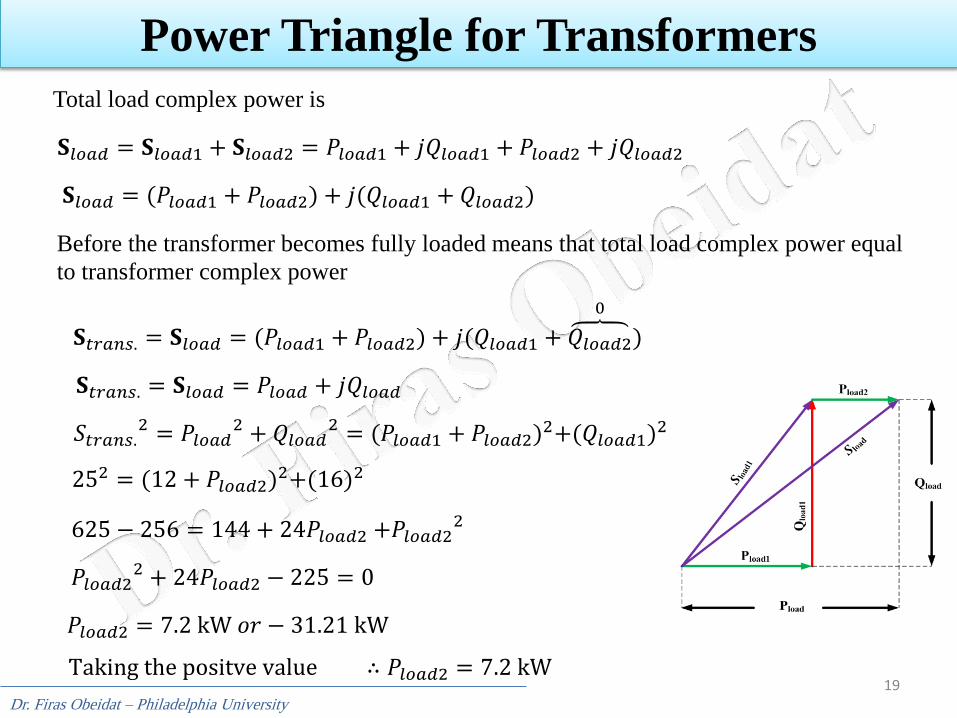
𝐒𝑙𝑜𝑎𝑑 = 𝐒𝑙𝑜𝑎𝑑1 + 𝐒𝑙𝑜𝑎𝑑2 = 𝑃𝑙𝑜𝑎𝑑1 + 𝑗𝑄𝑙𝑜𝑎𝑑1 + 𝑃𝑙𝑜𝑎𝑑2 + 𝑗𝑄𝑙𝑜𝑎𝑑2
𝐒𝑙𝑜𝑎𝑑 = (𝑃𝑙𝑜𝑎𝑑1 + 𝑃𝑙𝑜𝑎𝑑2) + 𝑗(𝑄𝑙𝑜𝑎𝑑1 + 𝑄𝑙𝑜𝑎𝑑2)
Before the transformer becomes fully loaded means that total load complex power equal
to transformer complex power
𝐒𝑡𝑟𝑎𝑛𝑠. = 𝐒𝑙𝑜𝑎𝑑 = (𝑃𝑙𝑜𝑎𝑑1 + 𝑃𝑙𝑜𝑎𝑑2) + 𝑗(𝑄𝑙𝑜𝑎𝑑1 + 𝑄𝑙𝑜𝑎𝑑2
0
)
𝐒𝑡𝑟𝑎𝑛𝑠. = 𝐒𝑙𝑜𝑎𝑑 = 𝑃𝑙𝑜𝑎𝑑 + 𝑗𝑄𝑙𝑜𝑎𝑑
Total load complex power is
𝑆𝑡𝑟𝑎𝑛𝑠.2 = 𝑃𝑙𝑜𝑎𝑑
2 + 𝑄𝑙𝑜𝑎𝑑2 = (𝑃𝑙𝑜𝑎𝑑1 + 𝑃𝑙𝑜𝑎𝑑2)2+(𝑄𝑙𝑜𝑎𝑑1)2
252 = (12 + 𝑃𝑙𝑜𝑎𝑑2)2+(16)2
625 − 256 = 144 + 24𝑃𝑙𝑜𝑎𝑑2 +𝑃𝑙𝑜𝑎𝑑22
𝑃𝑙𝑜𝑎𝑑22 + 24𝑃𝑙𝑜𝑎𝑑2 − 225 = 0
𝑃𝑙𝑜𝑎𝑑2 = 7.2 kW 𝑜𝑟 − 31.21 kW
Taking the positve value ∴ 𝑃𝑙𝑜𝑎𝑑2 = 7.2 kW
Dr. Firas Obeidat – Philadelphia University
20
Power Triangle for Transformers
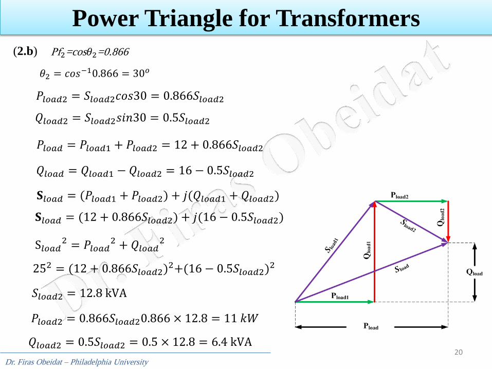
(2.b) Pf2=cos𝜃2=0.866
𝑃𝑙𝑜𝑎𝑑2 = 𝑆𝑙𝑜𝑎𝑑2𝑐𝑜𝑠30 = 0.866𝑆𝑙𝑜𝑎𝑑2
𝑄𝑙𝑜𝑎𝑑2 = 𝑆𝑙𝑜𝑎𝑑2𝑠𝑖𝑛30 = 0.5𝑆𝑙𝑜𝑎𝑑2
𝑃𝑙𝑜𝑎𝑑 = 𝑃𝑙𝑜𝑎𝑑1 + 𝑃𝑙𝑜𝑎𝑑2 = 12 + 0.866𝑆𝑙𝑜𝑎𝑑2
𝑄𝑙𝑜𝑎𝑑 = 𝑄𝑙𝑜𝑎𝑑1 − 𝑄𝑙𝑜𝑎𝑑2 = 16 − 0.5𝑆𝑙𝑜𝑎𝑑2
S𝑙𝑜𝑎𝑑2 = 𝑃𝑙𝑜𝑎𝑑
2 + 𝑄𝑙𝑜𝑎𝑑2
𝐒𝑙𝑜𝑎𝑑 = (𝑃𝑙𝑜𝑎𝑑1 + 𝑃𝑙𝑜𝑎𝑑2) + 𝑗(𝑄𝑙𝑜𝑎𝑑1 + 𝑄𝑙𝑜𝑎𝑑2)
𝐒𝑙𝑜𝑎𝑑 = (12 + 0.866𝑆𝑙𝑜𝑎𝑑2) + 𝑗(16 − 0.5𝑆𝑙𝑜𝑎𝑑2)
252 = (12 + 0.866𝑆𝑙𝑜𝑎𝑑2)2+(16 − 0.5𝑆𝑙𝑜𝑎𝑑2)2
𝑆𝑙𝑜𝑎𝑑2 = 12.8 kVA
𝑄𝑙𝑜𝑎𝑑2 = 0.5𝑆𝑙𝑜𝑎𝑑2 = 0.5 × 12.8 = 6.4 kVA
𝑃𝑙𝑜𝑎𝑑2 = 0.866𝑆𝑙𝑜𝑎𝑑20.866 × 12.8 = 11 𝑘𝑊
𝜃2 = 𝑐𝑜𝑠−10.866 = 30𝑜

Dr. Firas Obeidat – Philadelphia University
21
Power Factor Correction
Power factor correction is the process of increasing the power factor without
altering the voltage or current to the original load.
Most domestic loads (such as washing machines, air conditioners, and
refrigerators) and industrial loads (such as induction motors) are inductive and
operate at a low lagging power factor. Although the inductive nature of the load
cannot be changed, we can increase its power factor.
Most loads are inductive loads as shown in fig(a). A load’s Power factor is
improved or corrected by installing a capacitor in parallel with the load, as
shown in fig(b).
Dr. Firas Obeidat – Philadelphia University
22
Power Factor Correction
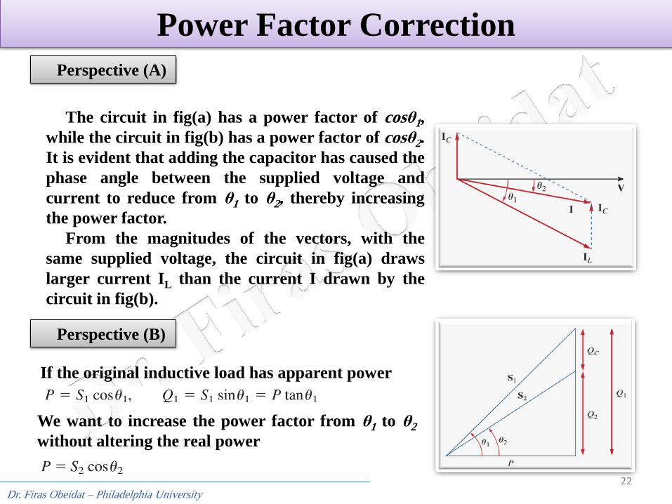
The circuit in fig(a) has a power factor of cosθ1,
while the circuit in fig(b) has a power factor of cosθ2.
It is evident that adding the capacitor has caused the
phase angle between the supplied voltage and
current to reduce from θ1 to θ2, thereby increasing
the power factor.
From the magnitudes of the vectors, with the
same supplied voltage, the circuit in fig(a) draws
larger current IL than the current I drawn by the
circuit in fig(b).
Perspective (A)
Perspective (B)
If the original inductive load has apparent power
We want to increase the power factor from θ1 to θ2
without altering the real power
Dr. Firas Obeidat – Philadelphia University
23
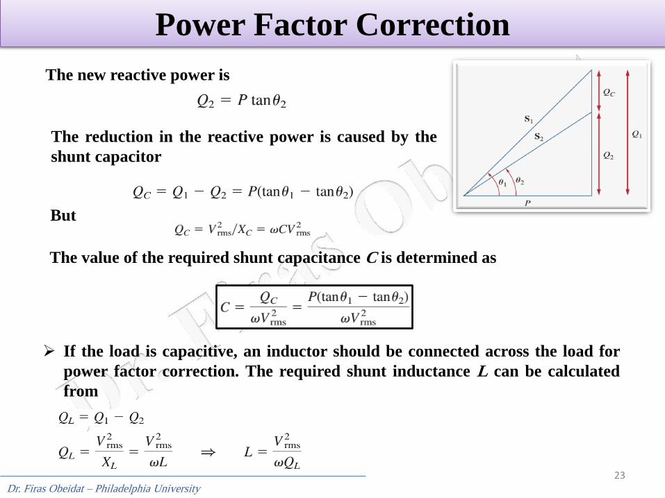
Power Factor Correction
The new reactive power is
The reduction in the reactive power is caused by the
shunt capacitor
But
The value of the required shunt capacitance C is determined as
If the load is capacitive, an inductor should be connected across the load for
power factor correction. The required shunt inductance L can be calculated
from
Dr. Firas Obeidat – Philadelphia University
24
Power Factor Correction
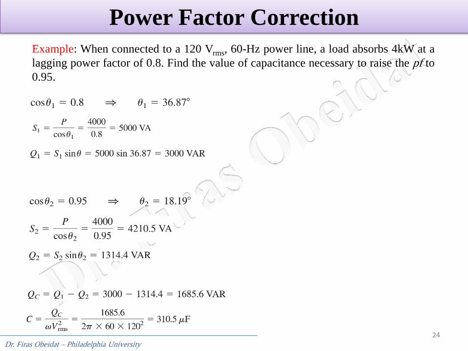
Example: When connected to a 120 Vrms, 60-Hz power line, a load absorbs 4kW at a
lagging power factor of 0.8. Find the value of capacitance necessary to raise the pf to
0.95.
Dr. Firas Obeidat – Philadelphia University
25
Power Factor Correction
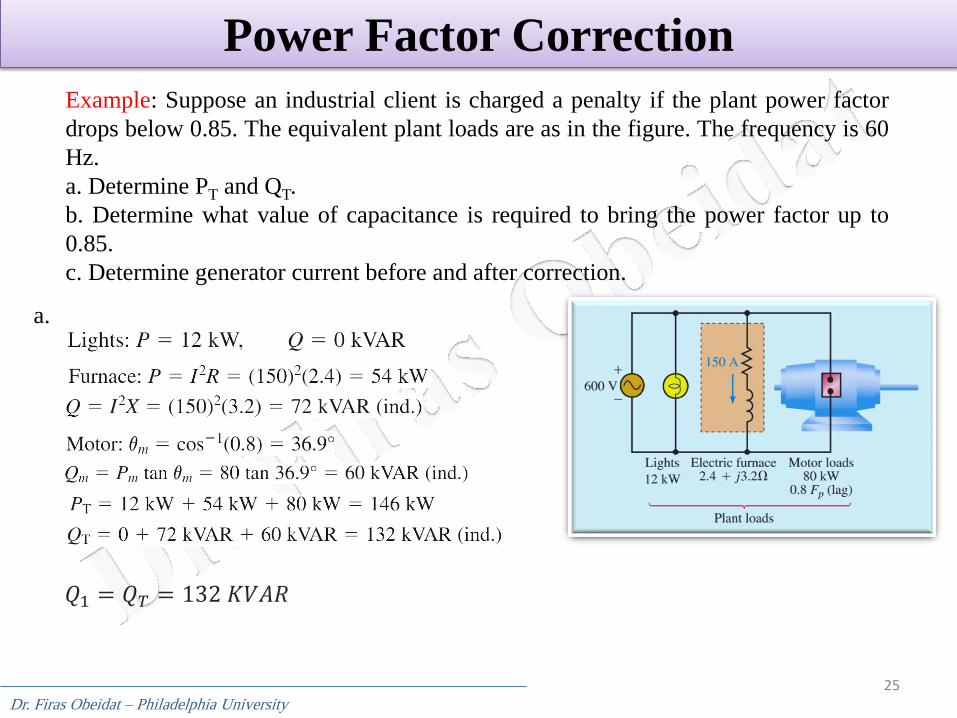
Example: Suppose an industrial client is charged a penalty if the plant power factor
drops below 0.85. The equivalent plant loads are as in the figure. The frequency is 60
Hz.
a. Determine PT and QT.
b. Determine what value of capacitance is required to bring the power factor up to
0.85.
c. Determine generator current before and after correction.
a.
𝑄1 = 𝑄𝑇 = 132 𝐾𝑉𝐴𝑅
Dr. Firas Obeidat – Philadelphia University
26
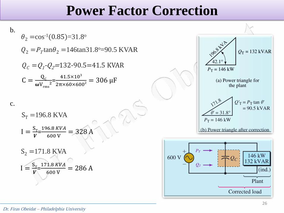
Power Factor Correction
b. 𝜃2 =cos-1(0.85)=31.8o
𝑄2 =PT tan𝜃2 =146tan31.8o=90.5 KVAR
𝑄𝐶 =Q1-Q2=132-90.5=41.5 KVAR
C =Q
C
𝛚Vrms
2=41.5×10³
2π×60×6002 = 306 μF
c.
ST =196.8 KVA
I =S
T
𝑽=
196.8 𝐾𝑉𝐴
600 V= 328 A
S2 =171.8 KVA
I =S
T
𝑽=
171.8 𝐾𝑉𝐴
600 V= 286 A

27