![Kalispell Ordinance No. 1745 › aviation › docs › Kalispell-Ordinance-1745.pdf11111111111111111 IIIII 1111111111111111111111111111111111111111 lllll lllll 111111111111111111 !:::;}]?!os](https://static.fdocuments.in/doc/165x107/5f213ebb2e287b5f527962c7/kalispell-ordinance-no-1745-a-aviation-a-docs-a-kalispell-ordinance-1745pdf.jpg)
Electric Circuits Count Alessandro Volta (1745 - 1827) André Marie AMPÈRE (1775 - 1836) Charles...
23
Electric Circuits Count Alessandro Volta (1745 - 1827) André Marie AMPÈRE (1775 - 1836) Charles Augustin de Coulomb (1736 – 1806) Georg Simon Ohm (1787 - 1854)
-
date post
20-Dec-2015 -
Category
Documents
-
view
224 -
download
2
Transcript of Electric Circuits Count Alessandro Volta (1745 - 1827) André Marie AMPÈRE (1775 - 1836) Charles...

Electric Circuits
Count Alessandro Volta(1745 - 1827)
André Marie AMPÈRE(1775 - 1836)
Charles Augustin de Coulomb (1736 – 1806)
Georg Simon Ohm(1787 - 1854)

Simple Electric Cell
Sulfuric acid
Zn+ Zn+
Zn+ Zn+
+++
___
Carbon Electrode
(+)
Zn Electrode(-)
•Two dissimilar metals or carbon rods in acid
•Zn+ ions enter acid leaving terminal negative
•Electrons leave carbon leaving it positive
•Terminals connected to external circuit
•‘Battery’ referred to several cells originally
wire

Electric Current
Electrons flow out of the negative terminal and toward the positive terminal electric current. (We will consider conventional current – positive charges move
Electric current I is defined as the rate at which charge flows past a given point per unit time.
1 C/s = 1A (ampere)

Electric Circuit
• It is necessary to have a complete circuit in order for current to flow.
• The symbol for a battery in a circuit diagram is:
+ _
9 voltsDevice
Current
“Conventional” current direction is opposite to actual electron flow direction which is – to +.
+

Ohm’s Law• For wires and other circuit devices, the current is
proportional to the voltage applied to its ends: I V• The current also depends on the amount of resistance
that the wire offers to the electrons for a given voltage V.
• We define a quantity called resistance R such that
• (Ohm’s Law)• The unit of resistance is the ohm which is represented
by the Greek capital omega ().
1V
A
VI
R

Resistors• A resistor is a circuit device that has a fixed resistance.
Resistor
Circuit symbol
Resistors obey Ohm’s law but not all circuit devices do.
I
V0
I
V0Resistor non-ohmic device
Resistor Code Calculator Resistor Code

Ohm’s Law
• Demo:
• Vary applied voltage V.
• Measure current I
• Does ratio remain constant?
V
I IR
V
I
slope = R
I
VR
How to calculate the resistance?
Include “resistivity” of material
Include geometry of resistor
V
I

Resistance
• Resistance
Resistance is defined to be the ratio of the applied voltage to the current passing through.
V
I IR
I
VR UNIT: OHM =
• Increase the length flow of electrons impeded
• Increase the cross sectional area flow facilitated
• Compare to straws or pipes
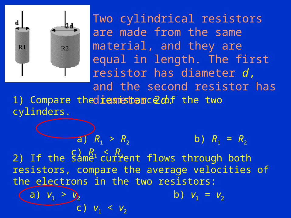
Two cylindrical resistors are made from the same material, and they are equal in length. The first resistor has diameter d, and the second resistor has diameter 2d.
1) Compare the resistance of the two cylinders.
a) R1 > R2 b) R1 = R2 c) R1 < R2
2) If the same current flows through both resistors, compare the average velocities of the electrons in the two resistors:
a) v1 > v2 b) v1 = v2 c) v1 < v2

Strain Gauge• A very thin metal wire patterned as
shown is bonded to some structure.• As the structure is deformed slightly,
this stretches the wire (slightly).– When this happens, the resistance of
the wire:
(a) decreases (b) increases (c) stays the same
Because the wire is slightly longer, is slightly increased. Also, because the overall volume of the wire is ~constant, increasing the length decreases the area A, which also increases the resistance.
By carefully measuring the change in resistance, the strain in the structure may be determined.
~R L A

Power in Electric Circuits• Electrical circuits can transmit and consume energy.• When a charge Q moves through a potential difference
V, the energy transferred is QV.• Power is energy/time and thus:
and thus:
P IV
energy QV QP power V IV
time t t

Notes on Power•The formula for power applies to devices that provide power such as a battery as well as to devices that consume or dissipate power such as resistors, light bulbs and electric motors.
•The formula for power can be combined with Ohm’s Law to give other versions:
22 V
P IV I RR
( )C J J
A V Watt Ws C s

Household Power•Electric companies usually bill by the kilowatt-hour (kWh.) which is the energy consumed by using 1.0 kW for one hour.
•Thus a 100 W light bulb could burn for 10 hours and consume 1.0 kWh.
•Electric circuits in a building are protected by a fuse or circuit breaker which shuts down the electricity in the circuit if the current exceeds a certain value. This prevents the wires from heating up when carrying too much current.
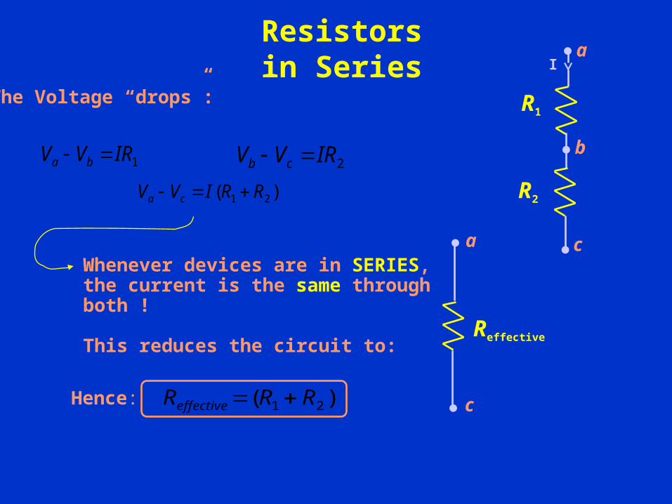
Resistorsin Series
a
c
Reffective
a
b
c
R1
R2
I
1IRVV ba 2IRVV cb
)( 21 RRIVV ca
The Voltage “drops”:
)( 21 RRReffective Hence:
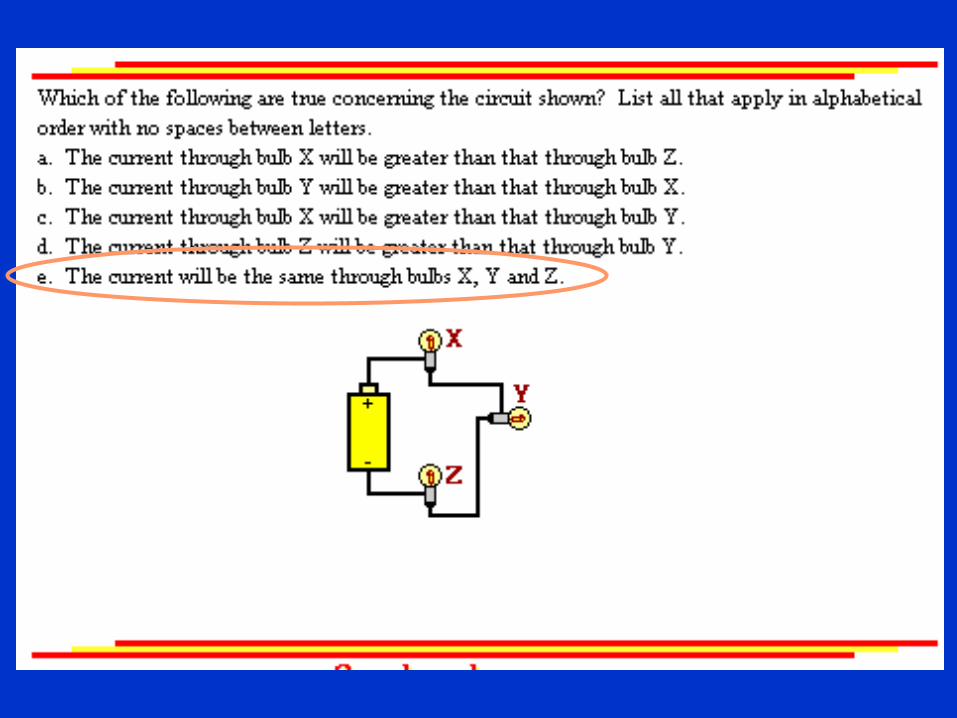
Whenever devices are in SERIES, the current is the same through both !
This reduces the circuit to:

Two resistors are connected in series to a battery with emf E. The resistances are such that R1 = 2R2.
Compare the current through R1 with the current through R2:
a) I1 > I2
b) I1 = I2
c) I1 < I2
What is the potential difference across R2?
a) V2 = E b) V2 = 1/2 E c) V2 = 1/3 E
Voltage Divider

Resistors in Parallel
a
d
I
I
R1 R2
I1 I2
V
Ia
dI
RV
• But current through R1 is not I ! Call it I1. Similarly, R2 I2.
KVL1 1 0V I R
2 2 0V I R
• What to do? IRV • Very generally, devices in parallel
have the same voltage drop
• How is I related to I 1 & I 2 ?
Current is conserved!
21 III
21 R
V
R
V
R
V
21
111
RRR

Circuit Practice
• Consider the circuit shown:
– What is the relation between Va -Vd and Va -Vc ?
(a) (Va -Vd) < (Va -Vc) (b) (Va -Vd) = (Va -Vc) (c) (Va -Vd) > (Va -Vc)
12VI1 I2
a
b
d c
50
20 80
(a) I1 < I2 (b) I1 = I2 (c) I1 > I2
1B – What is the relation between I1 and I2? 2
1

Circuit Practice
• Consider the circuit shown:
– What is the relation between Va -Vd and Va -Vc ?
(a) (Va -Vd) < (Va -Vc) (b) (Va -Vd) = (Va -Vc) (c) (Va -Vd) > (Va -Vc)
12VI1 I2
a
b
d c
50
20 80
1
•Point d and c are the same, electrically

Circuit Practice
(a) I1 < I2 (b) I1 = I2 (c) I1 > I2
– What is the relation between I1 and I2?
• Consider the circuit shown:
– What is the relation between Va -Vd and Va -Vc ?
(a) (Va -Vd) < (Va -Vc) (b) (Va -Vd) = (Va -Vc) (c) (Va -Vd) > (Va -Vc)
12VI1 I2
a
b
d c
50
20 80
• Note that: Vb -Vd = Vb -Vc • Therefore,
)80()20( 21 II 21 4II
2

Summary of Simple Circuits
1 2 3 ...equivalentR R R R • Resistors in series:
• Resistors in parallel: 1 2 3
1 1 1 1...
R equivalent R R R
Current thru is same; Voltage drop across is IRi
Voltage drop across is same; Current thru is V/Ri

Two identical light bulbs are represented by the resistors R2 & R3 (R2 = R3 ). The switch S is initially open.
If switch S is closed, what happens to the brightness of the bulb R2?
a) It increases b) It decreases c) It doesn’t change
What happens to the current I, after the switch is closed ?
a) Iafter = 1/2 Ibefore
b) Iafter = Ibefore
c) Iafter = 2 Ibefore