Black Market Study Sports betting, poker & casino Danish Online Gambling Association 11/5 2015.

Electric Betting System for Poker Team 62 – Anand Giridharan, Umang Chavan, Varun Pitta
ECE 445 Design Document – Spring 2019 TA: Nicholas Ratajczyk
1. INTRODUCTION Objective Texas Hold’em is a variant of the card game of poker. Each player in the game is dealt two cards face down and the dealer goes through three rounds of community betting flipping over 5 cards in total. Each player then makes bets on each round based on the strength of their hand. Each player in the game starts with the same amount of money to use while betting. The money is represented using poker “chips,” which are small discs that are often made of plastic or clay. Without these chips, playing poker becomes very difficult. If a group of people wish to play poker, they would need a deck of cards and a poker chip set. The issue is that not everyone owns a poker chip set and those who do only have a limited amount of chips. This restricts the number of people that can play and how much money can be bet. Poker sets can be rather expensive and sometimes if the chips are made from authentic clay, they can chip and break easily. The problem statement that we are addressing is to see if there is a more effective way of playing poker for cheap without worrying about chips. Our proposed solution is an electronic betting system that completely eradicates the need of physical poker chips. The idea is to have a centralized unit where all betting happens, and each player can see the community pot. Each player will also have their own device that allows them to see their own money and make poker actions such as raising the bet or calling the bet. By taking away the need to use poker chips, everyday people can play poker without having to worry about the financial restraints and the game restraints. Background The idea of removing accessories from games and using an electric alternative has been around for a while. Monopoly Electronic Banking Edition by Hasbro eliminated the need for paper cash that is normally used in games. Instead they created a debit card system, where each player swipes a machine to perform all transactions with the bank or with other players. The purpose of this was to remove the hassle of having so much paper laying around. All the math and counting is done by the middle unit and the player only has to know what action they want to take. The debit cards in this game use magnetic strips to take care of player identification Our goals are similar to this, but we also wanted to add the feature where each player knows the amount of money they hold as well as the community pot. Instead of using magnetic strips, our player identification will be handled with RFID readers. The hope for the end-product is that

it will be efficient enough to eliminate poker chips, be affordable, and still provide enjoyment to the game. High-Level Requirements
• Player should be able to join the game at any time and see the amount of money other players have as well as the amount of money in the community pot.
• Players should be able to raise, call, or fold from their device, and the central hub should display the chosen action.
• All devices including the central display must be powered with a battery pack. The battery pack must last the duration of the game
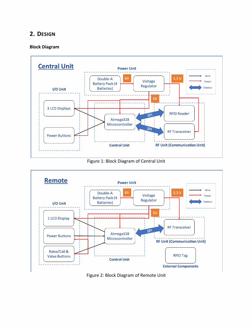
2. DESIGN Block Diagram
Figure 1: Block Diagram of Central Unit
Figure 2: Block Diagram of Remote Unit

Physical Design
Figure 3: Physical Layout of Full Apparatus
Our physical design consists of essentially a main display device and the remote(s) for each player. On the main display we plan to display:
1) Each Players Total Money 2) Total Pot Money 3) Current Player
The main display will also contain a power button to turn the device on and off. For the remote(s) we plan to display:
1) Player’s total money We will also have various buttons and indicators such as:

1) Call push button 2) Raise push button 3) Up push button (to increase amount you’d like raise by) 4) Down push button (to decrease amount you’d like to raise by) 5) Power button
Functional Overview Power Supply We require a power supply for nearly all our units. We will be using a battery pack with four AA batteries for our power supply.
Requirements Verification
1. Batteries power all our LCDs and Microcontrollers
1. Test this by using a Multimeter (Voltmeter specifically) to see how much voltage is outputted from N number of batteries and see if they reach the minimum needed to power all the components.
Voltage Regulator We are using two voltage regulators, one for our RF transceiver and one for our microcontroller/LCDs. This is necessary to be able to step down our 6 V input (4 batteries) to 3.3 V max for our RF transceiver (STMicroelectronics LD1117AV33), and 5 V max for our microcontroller and LCDs (Sparkfun L7805).
Figure 4: 5V Regulator
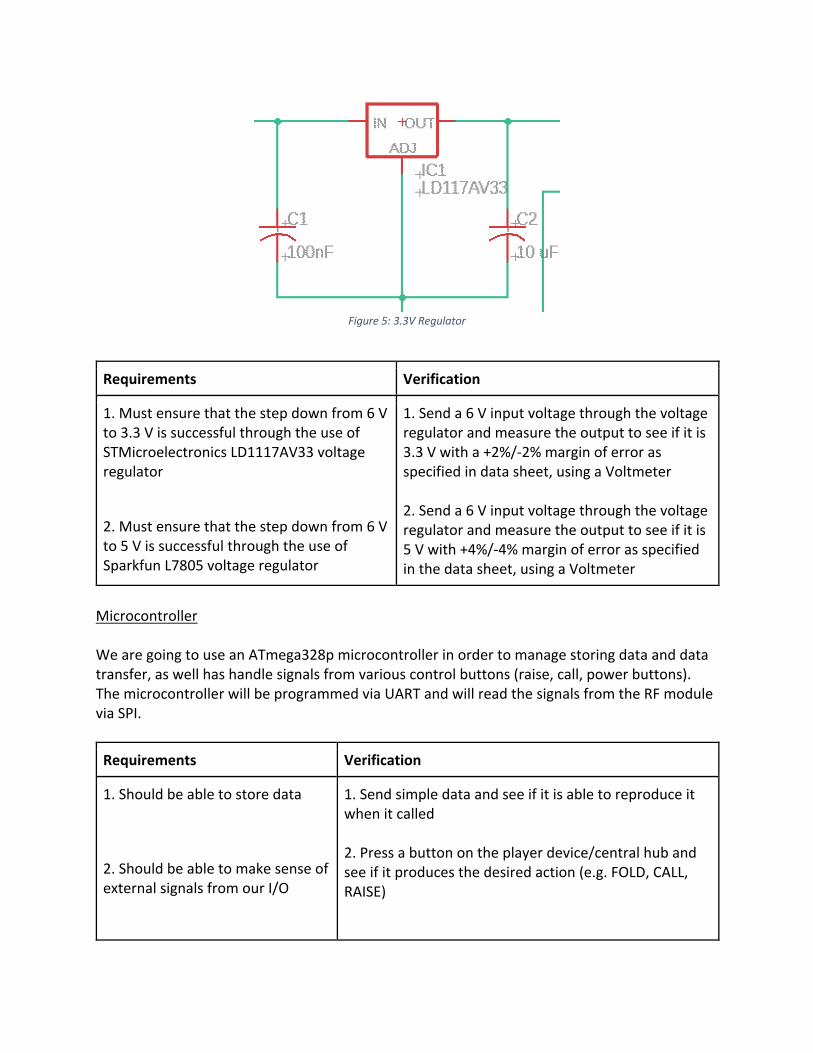
Figure 5: 3.3V Regulator
Requirements Verification
1. Must ensure that the step down from 6 V to 3.3 V is successful through the use of STMicroelectronics LD1117AV33 voltage regulator
2. Must ensure that the step down from 6 V to 5 V is successful through the use of Sparkfun L7805 voltage regulator
1. Send a 6 V input voltage through the voltage regulator and measure the output to see if it is 3.3 V with a +2%/-2% margin of error as specified in data sheet, using a Voltmeter 2. Send a 6 V input voltage through the voltage regulator and measure the output to see if it is 5 V with +4%/-4% margin of error as specified in the data sheet, using a Voltmeter
Microcontroller We are going to use an ATmega328p microcontroller in order to manage storing data and data transfer, as well has handle signals from various control buttons (raise, call, power buttons). The microcontroller will be programmed via UART and will read the signals from the RF module via SPI.
Requirements Verification
1. Should be able to store data
2. Should be able to make sense of external signals from our I/O
1. Send simple data and see if it is able to reproduce it when it called 2. Press a button on the player device/central hub and see if it produces the desired action (e.g. FOLD, CALL, RAISE)

3. Should be able to load data and send it via appropriate circuit connection
3. Send data via SPI as well as data through general wires(e.g. Microcontroller to LCD) to ensure both methods of communications work
Power Button This will simply serve as a switch in our circuit to disconnect the voltage source from the rest of the components.
Requirements Verification
1. Switch successfully turns on or off the console
1. Test the switch for a set number of trials and considered success if all trials work
Call Button This button will only be on the player device, and it will be used to send a signal to the central hub display via the RF module. The central hub display will then automatically update the call amount to the community pot.
Requirements Verification
1. Match the current bet in the pot, and set it as the bet for the current player successfully
1. Test by having a set current bet value for a player on the display, and seeing if by pressing CALL the bet is matched on the central hub display E.g. Current Pot Player 1: $0 Player 2: $0 Player 3: $0 Actions: Player 1 RAISES to $10 Player 2 presses CALL Player 3 presses FOLD Current Pot after Actions: Player 1: $10 Player 2: $10 Player 3: $0
2. The microcontroller on player device should receive a signal from the CALL button > 95% of the time and store it to be sent to the central hub by the RF transceiver 3. Must easily be pressable
Player 2’s total matched that of Player 1’s after pressing CALL 2. Press CALL button 100 times and see if a signal is received at least 96 times
3. Press button and ensure it can be done without using too much effort
Raise Button This button will be only on the player device, and it will be used to send a signal to transfer the data from the player device microcontroller to the central display microcontroller via the RF module.
Requirements Verification
1. Must properly register the new bet value
2. The microcontroller on player device should receive a signal from the RAISE button > 95% of the time and store it to be sent to the central hub by the RF transceiver 3. Must easily be pressable
1. On the LCD display, change the current bet value by pressing UP and DOWN and selecting RAISE and checking if the value changes on the central hub display 2. Press RAISE button 100 times and see if a signal is received at least 96 times
3. Press button and ensure it can be done without using too much effort
Up & Down Button These buttons will only be on the player devices, and they will be used to control how much the player wants to increase or decrease the current bet.

Requirements Verification
1. The UP button should be able to raise the amount to >= double the bet. It should only work after pressing the RAISE button after the action.
2. The microcontroller on player device should receive a signal from the UP button > 95% of the time and store it to be sent to the central hub by the RF transceiver 3. Must easily be pressable
1. Test by pressing the UP button; the amount on the LCD should change from what the current bet is to double that amount, then plus 1 afterward. E.g. Current bet = 10 (Press UP) Current bet = 20 (Press UP) Current bet = 21 (press RAISE)
2. Press UP button 100 times and see if a signal is received at least 96 times
3. Press button and ensure it can be done without using too much effort
1. The DOWN button should not allow user to go below the current bet and if he/she had raised previously it should allow them to go back to a specified value.It should only work after pressing the RAISE button after the action.
1. Test by pressing DOWN button; the amount on the LCD should change only if it was above the original bet amount from previously pressing the UP button E.g. Current Bet = 10 (press DOWN) Current Bet = 10 (press UP) Current Bet = 20 (press UP) Current Bet = 21 (press DOWN) Current Bet = 20 (Press DOWN) Current Bet = 10 (press RAISE)

2. The microcontroller on player device should receive a signal from the DOWN button > 95% of the time and store it to be sent to the central hub by the RF transceiver
3. Must easily be pressable
2. Press DOWN button 100 times and see if a signal is received at least 96 times
3. Press button and ensure it can be done without using too much effort
Fold Button This button will only be on the player device, and it will be used to send a signal to the central hub display via the RF module. The player remote will be disabled for the rest of the round, where round is when N-1 players have folded.
Requirements Verification
1. Will disable player’s moves for rest of round
2. The microcontroller on player device should receive a signal from the FOLD button > 95% of the time and store it to be sent to the central hub by the RF transceiver 3. Must easily be pressable
1. Press other buttons on the player remote and ensure their desired action does not take place, due to the player folding
2. Press FOLD button 100 times and see if a signal is received at least 96 times
3. Press button and ensure it can be done without using too much effort
Central Hub Display

The central display device will contain three LCD displays, with two of them containing the current players, their current chip amounts. The third one will contain the community pot,the current bet, what the current player’s action is, and who is going. The data being displayed on the LCD screens will be coming from the microcontroller storage.
Requirements Verification
1. Should be able to display characters with enough brightness, so user does not strain to read the displayed information
1. Try various potentiometer settings until reaching a brightness that
Player Device Display The player device will have one LCD screen so that the user can see how much money he/she has left and how much money he/she wants to raise for the current turn. The data being displayed on the LCD screen will be coming from the microcontroller storage.
Figure 6: LCD 16x2 Display
Requirements Verification

1. Should be able to display characters with enough brightness, so user does not strain to read the displayed information
1. Try various potentiometer settings until reaching a brightness that
RFID Tag The player device will contain the RFID tag that will be attached to each player device/remote to allow a player to successfully join the game and begin the mode of communication between the central hub and the player device. To join the game the player must scan his or her RFID on the back of the player device on the RFID reader on the central hub.
Requirements Verification
1. The player should be able to join the game using their respective RFID tag and scan in using the RFID reader on the central hub.
1. Test the RFID tag and reader by attaching it to an LED and having it light up if the RFID is successfully read; test this with all the RFIDs we will have
RF Transceiver The RF Transceiver is necessary for communication between the Player Device and Central Hub, as we must pass data to be displayed almost every I/O action. The model we will be using is the NRF24L01. This has a transmit power of 12mA, and operates at a 1.9 - 3.6 V range. The frequency bandwidth in which this transceiver operates is 2.4 GHz. The amount of baud (how many times the signal changes per second) ranges from 250 Kbps to 2 Mbps.

Figure 7: NRF24L01 Transceiver
Requirements Verification
1. The transfer of data from the Player Device transceiver and Central Hub transceiver(and vice versa), should consistently be correct and instant.
1. Send simple data between the Central Hub and Player Device, both hard-coded and dynamically, to be displayed on the LCD display. Do this several 100 times to ensure the communication channels work to our specified speed (~250 Kbps) and with almost 100% accuracy.
RFID Reader The RFID Reader serves the purpose of reading the individual player’s RFID tags and allows them to enter the game. This will only be on the Central Hub, and will only be used once by each player then the software will keep the rotation/turns of each player going.
Requirements Verification

1. Ensure the Player Devices can be read into the game through the use of the RFID reader
1. Test each individual RFID tag on the reader and ensure the reader is able to identify each separately and open a method of communication between the Player Device and Central Hub. If successful, all RFID tags will be saved on the Central Hub’s microcontroller
Figure 8: NRF24L01 Transceiver
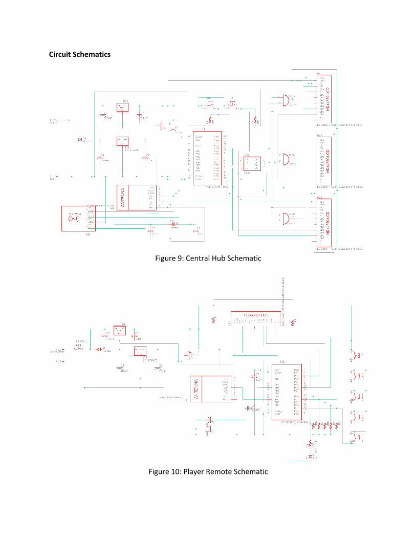
Circuit Schematics
Figure 9: Central Hub Schematic
Figure 10: Player Remote Schematic

Flow Diagrams
Figure 11: Game Setup Flow

Figure 12: Game State Flow

Tolerance Analysis One variable factor that will determine our project success is if the device and central hub battery life lasts the duration of the game. One of our main tasks to handle is to ensure that the current power solution we have now will be sufficient in any given situation. Therefore, we are testing the tolerance of our battery pack solution, as well as the power consumption of the components of our circuit, to ensure that we are allowing enough runtime for the game. The max duration for game time we are going to set is 2.5 hours. In our circuit, we have our 6V battery pack connected in parallel with two voltage regulators in order to bring it down to 5V and 3.3V respectively. Since our initial voltage is fairly close in value to the dropped down voltages, the regulator efficiency will be fairly good, and less heat will be dissipated. If our initial voltage was larger, we may have to consider switch converters (such as the buck converter) which dissipates less heat overall. In terms of battery life, the microcontroller is going to require the most power as it provides and receives signals from all of the other components in our device. Using various parameters provided in the ATmega328p data sheet, we did a tolerance analysis on battery life in order to see if the various parameters still enabled the 2.5-hour gameplay that we intend to aim for.
𝐸𝑓𝑓𝑖𝑐𝑖𝑒𝑛𝑐𝑦 =𝑃𝑜𝑤𝑒𝑟-./𝑃𝑜𝑤𝑒𝑟01
=𝑉𝑜𝑙𝑡𝑎𝑔𝑒7./𝑉𝑜𝑙𝑡𝑎𝑔𝑒81
𝑅𝑢𝑛𝑡𝑖𝑚𝑒 = 𝐶ℎ𝑎𝑟𝑔𝑒>> ∗𝐸𝑓𝑓𝑖𝑐𝑖𝑒𝑛𝑐𝑦𝑙𝑜𝑎𝑑A7BCDEDFB
The ATmega328p has an internal oscillator of 8 MHz. In our scenario, we can provide either 3.3V or 5V to the microcontroller, but we will be providing 5V to the microcontroller for better performance. Using the parameters of 8 MHz and Vcc = 5V for the ATmega328p, the voltage regulator efficiency is around 75%. The microcontroller, for these parameters, draws about 6.3mA. We can then use the above equations to get our results.
5𝑉6𝑉 = 0.83333
2500𝑚𝐴𝐻 ∗0.833336.93𝑚𝐴 = 300.624ℎ𝑜𝑢𝑟𝑠
Although the microcontroller has an internal oscillator, we will be using a 16 MHz crystal oscillator to provide the near-constant frequency to the microcontroller. According to the ATmega328p data sheet, for an input voltage of 5V and a frequency of 16 MHz, the microcontroller draws about 12mA.
5𝑉6𝑉 = 0.83333
2500𝑚𝐴𝐻 ∗0.8333312𝑚𝐴 = 173.61ℎ𝑜𝑢𝑟𝑠

We will be doing additional testing with the individual components integrated in our device, and we will re-do an analysis to ensure that our battery life still remains above the 2.5 hour time we have allocated. 3. COST & SCHEDULE Cost Since we are expecting to finish the entire project during the duration of the semester, we don’t need to account for partial work calculations. We estimate our development costs to be $30/hour, 15 hours/week for 3 people. Therefore, our total development costs will be:
3 ∗$30ℎ𝑟 ∗
15ℎ𝑟𝑠𝑤𝑒𝑒𝑘 ∗ 16𝑤𝑒𝑒𝑘𝑠 = $21,600
Part Cost (Individual) Cost (Project)
LCD Display (HD44780) $2.71 (16x2) $5.61 (20x4) $19.16
Microcontroller (ATMega328P) $4.30 $17.20
RF Transceiver (NRF24L01) $1.75 $7.00 RFID Reader (RC522) $12.99 $12.99
Voltage Regulator $0.95 (L7805) $0.54 (LD1117AV33) $5.96
Logic Gates (SN74HC08AN) $0.44 $1.76 Decoder (CD4555BEE4) $0.46 $1.84
Resistors/Capacitors Pack $15.90 $15.90 Battery Pack (4xAA) $1.95 $7.80
Push Buttons $0.25 $4.00 Potentiometer $0.95 $3.80 16 MHz Crystal $0.95 $3.80
Total $101.21 We are planning on building only one unit, therefore our total development costs including work hours is $21,701.21
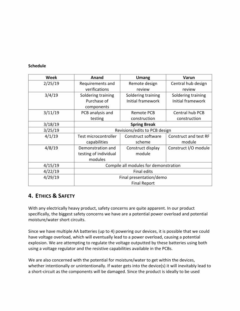
Schedule
Week Anand Umang Varun 2/25/19 Requirements and
verifications Remote design
review Central hub design
review 3/4/19 Soldering training
Purchase of components
Soldering training Initial framework
Soldering training Initial framework
3/11/19 PCB analysis and testing
Remote PCB construction
Central hub PCB construction
3/18/19 Spring Break 3/25/19 Revisions/edits to PCB design 4/1/19 Test microcontroller
capabilities Construct software
scheme Construct and test RF
module 4/8/19 Demonstration and
testing of individual modules
Construct display module
Construct I/O module
4/15/19 Compile all modules for demonstration 4/22/19 Final edits 4/29/19 Final presentation/demo
Final Report 4. ETHICS & SAFETY With any electrically heavy product, safety concerns are quite apparent. In our product specifically, the biggest safety concerns we have are a potential power overload and potential moisture/water short circuits. Since we have multiple AA batteries (up to 4) powering our devices, it is possible that we could have voltage overload, which will eventually lead to a power overload, causing a potential explosion. We are attempting to regulate the voltage outputted by these batteries using both using a voltage regulator and the resistive capabilities available in the PCBs. We are also concerned with the potential for moisture/water to get within the devices, whether intentionally or unintentionally. If water gets into the device(s) it will inevitably lead to a short-circuit as the components will be damaged. Since the product is ideally to be used

indoors, or in an area where water cannot get into the device, a normal casing should be enough. The goal of our product is to bring a fun, and fair system to the common or even professional poker player, by eliminating chips from the game and allowing for a fair system of money representation. By doing so we eliminate potential cheating from the game which satisfies IEEE Code of Ethics, #2: “to avoid real or perceived conflicts of interest whenever possible, and to disclose them to affected parties when they do exist” [2]. Thus, this product serves to not only allow for more players to participate at once, but also allows for a cheat-free system by getting rid of the need for physical chips. While our product is meant to be harmless, as poker is simply a card game, it may aggravate certain illnesses such as a gambling addiction. This is in violation of IEEE Code of Ethics, #9: “to avoid injuring others, their property, reputation, or employment by false or malicious action”[2]. With the potential ease of this product, there is a chance of further aggravation to a person’s already harmful addiction. We do not have a means to solve such a health issue - we are assuming that players are playing responsibly and are careful with their money. 5. REFERENCES [1] N/A, N/A. “What Are ESC, UBEC and BEC.” Oscar Liang, 26 Nov. 2016, oscarliang.com/what-is-esc-uber-bec-quadcopter/. [2] Publications, IEEE. “IEEE Code of Ethics.” IEEE - Advancing Technology for Humanity, www.ieee.org/about/corporate/governance/p7-8.html. [3] ATMega, ATMega. "ATMega628." Sparkfun. N.p., 2016. Web. 21 Feb. 2019. [4] Igor, Ardunio. "Arduino's ATMega328 Power Consumption." Gadget Makers' Blog. N.p., 14 Dec. 2013. Web. 22 Feb. 2019. [5] Julius, Bob. "Powerdis." Low Pass Filters. N.p., 2015. Web. 22 Feb. 2019. N/A, N/A. "What Are ESC, UBEC and BEC." Oscar Liang. N.p., 26 Nov. 2016. Web. [6] Publications, IEEE. "IEEE Code of Ethics." IEEE - Advancing Technology for Humanity. N.p., n.d. Web. [7] QU1500_US_UL1, QU1500_US_UL1. "QU1500_US_UL1." D2ei442zrkqy2u.cloudfront. N.p., 2015. Web. 21 Feb. 2019.