Electric Bedroom Slideout-Web - Camper Parts, Camper ... Bedroom... · Step 2 - If YES, at the...
15
ELECTRIC BEDROOM SLIDEOUT SYSTEM OPERATION AND SERVICE MANUAL
Transcript of Electric Bedroom Slideout-Web - Camper Parts, Camper ... Bedroom... · Step 2 - If YES, at the...

ELECTRIC BEDROOM SLIDEOUT SYSTEM
OPERATION AND SERVICE MANUAL

TABLE OF CONTENTS
SYSTEM……………………………………………........….…..Warning…………………………………........……....Description………………………………........……..Prior to Operation…………………….....………System Maintenance……….............………..
OPERATION…………………………………........……………Warning....................................................Extending Slideout Room….......………….Retracting Slideout Room…….......……...Manual Operation……………….......……….
SERVICE…………………………..………………........………Adjustment Instructions……….......…………..System Components....................................Troubleshooting…………………….........………Wiring Diagram…………………….….......………Ordering Parts…………......………………………
44455
66667
99
10121516
3
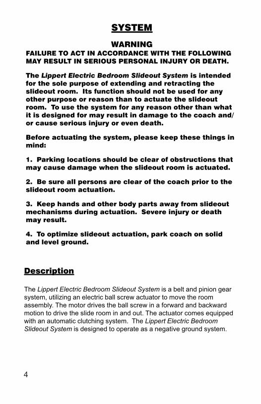
SYSTEM
WARNINGFAILURE TO ACT IN ACCORDANCE WITH THE FOLLOWINGMAY RESULT IN SERIOUS PERSONAL INJURY OR DEATH.
The Lippert Electric Bedroom Slideout System is intendedfor the sole purpose of extending and retracting theslideout room. Its function should not be used for anyother purpose or reason than to actuate the slideoutroom. To use the system for any reason other than whatit is designed for may result in damage to the coach and/or cause serious injury or even death.
Before actuating the system, please keep these things inmind:
1. Parking locations should be clear of obstructions thatmay cause damage when the slideout room is actuated.
2. Be sure all persons are clear of the coach prior to theslideout room actuation.
3. Keep hands and other body parts away from slideoutmechanisms during actuation. Severe injury or deathmay result.
4. To optimize slideout actuation, park coach on solidand level ground.
Description
The Lippert Electric Bedroom Slideout System is a belt and pinion gearsystem, utilizing an electric ball screw actuator to move the roomassembly. The motor drives the ball screw in a forward and backwardmotion to drive the slide room in and out. The actuator comes equippedwith an automatic clutching system. The Lippert Electric BedroomSlideout System is designed to operate as a negative ground system.
4

SYSTEM MAINTENANCE
The Lippert Electric Bedroom Slideout System has been static tested toover 2,500 continuous cycles with out any noticeable wear to rotating orsliding parts. It is recommended that when operating in harshenvironments (road salt, ice build up, etc.) the moving parts be keptclean and can be washed with mild soap and water. No grease orlubrication is necessary and in some situations may be detrimental to theenvironment and long term dependability of the system.
Electrical System Maintenance
For optimum performance, the slide-out system requires full batterycurrent and voltage. The battery must be maintained at full capacity.Other than good battery maintenance, check the terminals and otherconnections at the battery, the control switch, and the electric actuatormotor for corrosion, and loose or damaged terminals. Check motorleads under the trailer chassis. Since these connections are subject todamage from road debris, be sure they are in good condition.
NOTE: The Lippert Electric Bedroom Slideout System is designed tooperate as a negative ground system. A negative ground system utilizesthe chassis frame as a ground and an independent ground wire back tobattery is necessary (see page 15 for wiring diagram). It is important thatthe electrical components have good wire to chassis contact. To ensurethe best possible ground, a star washer should be used. Over 90% of aunit’s electrical problems are due to bad ground connections.
Mechanical Maintenance
Although the system is designed to be almost maintenance free, actuatethe room once or twice a month to keep the seals and internal movingparts lubricated.
Check for any visible signs of external damage after and beforemovement of the travel trailer.
NOTE: For long-term storage: It is recommend that the room be closed(retracted).
PRIOR TO OPERATION
Prior to operating the Lippert Electric Bedroom Slideout System, followthese four (4) guidelines:
1. Coach should be parked on the most level surface available.2. Leveling or stabilizing system should be actuated to ensure coach will not move during operation of Bed Lift System.3. Be sure battery is fully charged.4. Be sure to keep all persons and pets clear of Bed Lift System during operation.
5

OPERATION
WARNINGFAILURE TO ACT IN ACCORDANCE WITH THE FOLLOWINGMAY RESULT IN SERIOUS PERSONAL INJURY OR DEATH.
ALWAYS MAKE SURE THAT THE SLIDEOUT ROOM PATH IS CLEAROF PEOPLE AND OBJECTS BEFORE AND DURING OPERATION OFTHE SLIDEOUT ROOM.
ALWAYS KEEP AWAY FROM THE SLIDE RAILS WHEN THE ROOM ISBEING OPERATED. THE GEAR ASSEMBLY MAY PINCH OR CATCHON LOOSE CLOTHING CAUSING PERSONAL INJURY.
INSTALL TRANSIT BARS (IF SO EQUIPPED) ON THE SLIDEOUTROOM DURING STORAGE AND TRANSPORTATION.
EXTENDING SLIDEOUT ROOM
1. Level the unit.2. Verify the battery is fully charged and hooked-up to the electrical
system.3. Remove the transit bars (if so equipped).4. Press and hold the IN/OUT switch (Fig. 1B) in the OUT position until
the room is fully extended and stops moving.5. Release the switch, which will lock the room into position.NOTE: If the slideout switch is held after the room in fully extended, thecontrol will sense that the room has stopped and will shut off the motorafter a few seconds.
RETRACTING SLIDEOUT ROOM
1. Verify the battery is fully charged and hooked-up to the electricalsystem.
2. Press and hold the IN/OUT switch (Fig. 1C) in the IN position untilthe room is fully retracted and stops moving.
3. Release the switch, which will lock the room into position.NOTE: If the slideout switch is held after the room in fully retracted, the control will sense that the room has stopped and will shut off the
motor after a few seconds.4. Install the transit bars (if so equipped).
6

B
C
MANUAL OPERATION
The Lippert Electric slide comes with a manual over ride system. Locatethe motor assembly under the bed frame. Locate the drive gear box,Fig. 3 ,page 7. The Manual Override coupler extends from the devicegear box and accepts a 3/4” wrench, socket or lug. The coupler is heldin place by a hitch pin. Simply take the wrench, ratchet or drill with a nutdriver and rotate it clockwise to retract and counterclockwise to extendslide-out. It is important to note that you DO NOT need to attempt todisengage the motor as the actuator is “manual ready” Just hook up andcrank.
Fig.1
7
WARNING!Always disconnect battery from system prior to manually operating system. Failureto disconnect battery can cause electricity to backfeed through the motor andcause serious damage to the system as well as void the warranty.
WARNING!The gears can be stripped out if the room is manually retracted/extended to it’sfullest extent and the operator continues to rotate manual override.Any damage due to misuse of the Manual Override feature will disqualify any andall claims to the Limited Warranty.

MANUAL OPERATION
Fig. 2
Fig. 3
Motor Assembly
Motor
Drive Gear
Drive Gear
Manual Overdrive
8

SERVICE
MECHANICAL ROOM ADJUSTMENT
NOTE: All slideout room adjustments must be performed by certified service technicians. Adjustments made by non-certified persons may void any and all warranty claims.
1. Retract room completely.2. Loosen hex bots on Alignment Plates (Fig. 4A,).3. Place jaws of adjustable wrench on Drive Tube (Fig. 4B,).4. Rotate drive tube until both sides of slide room are sealed in unit.5. Tighten Adjustment Plate bolts.
Fig.4
A
B
(SECOND BOLT NOT SHOWN)
9
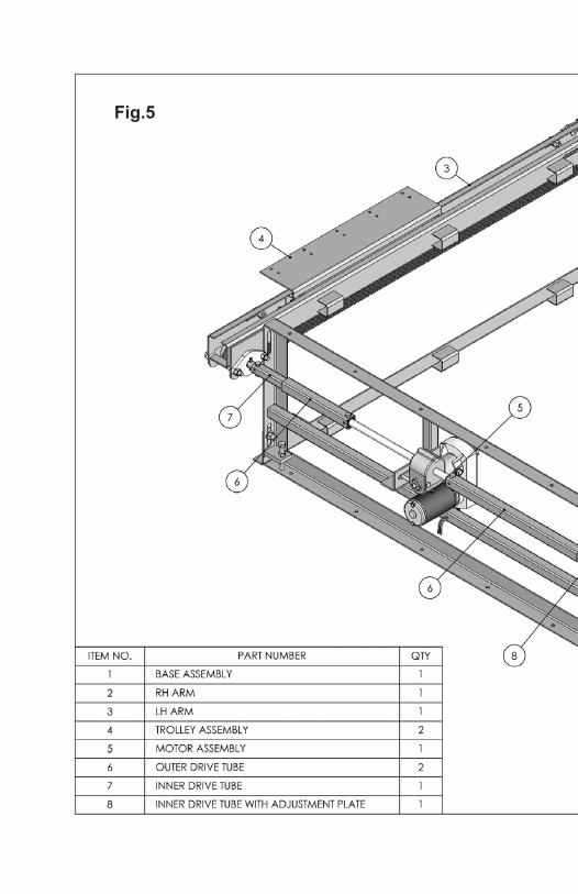
Fig.5


TROUBLESHOOTING
The Lippert Electric Bedroom Slideout System is only one of fourinterrelated slideout room system components. These four componentsare: chassis, room, coach, and Lippert Electric Bedroom SlideoutSystem. Each one needs to function correctly with the others ormisalignment problems will occur.
Every travel trailer has its own personality and what may work to fix onetrailer may not work on another even if the symptoms appear to be thesame.
When something restricts room travel, system performance will beunpredictable. It is very important that slide tubes be free ofcontamination and allowed to travel full distance (Stroke). Ice or mudbuildup during travel is an example of some types of contamination thatcan occur.
When you begin to troubleshoot the system, make sure the battery isfully charged, there are no visible signs of external damage to theactuator or motor and that the motor is wired correctly and allconnections are secure.
During troubleshooting, remember that if you change something, thatchange may affect something else. Be sure any changes you make willnot create a new problem.
You can obtain additional information on theLippert Electric Slideout System
by calling 866-524-7821.
12

System Troubleshooting ChartThe following troubleshooting chart outlines some common problems, their causes and possible corrective actions.When reference is made to “Power Unit” it is referring to the motor and actuator as a complete assembly. All PowerUnits are shipped from the factory with a serial number and date code, which should be given to the servicetechnician when asking for assistance.
ROOM DOESN’T MOVE WHEN SWITCH IS PRESSED
Probable cause Corrective action
Restrictions both inside and out side unit. Check for and clear restriction.
Low battery voltage, blown fuse, defective wiring. Check battery. Charge battery or add auxiliary power source. Check battery terminals, and all other wiring. Look for loose/corroded connectors.
Power unit not functioning. See “Troubleshooting” on page 5.
POWER UNIT RUNS, BUT ROOM DOES NOT MOVE
Actuator not attached to front mounting Check jam nuts/nylock nuts. Be sure thatdrive bracket. they are properly tightened and adjusted.
Bad motor or gear housing. Replace motor.
POWER UNIT RUNS, BUT ROOM MOVES SLOWLY
Low battery, poor ground, extremely Charge battery, and check ground wire.low outdoor temperature.
Room is in a bind. Check to see that room is properly adjusted
ROOM STALLS IN MID TRAVEL
Actuator in a bind. Crank manual override and move room short distance then retry electric switch to move room.
Bad actuator. Replace actuator if above instructions do not work.
NOTES:· If the slideout room will not retract there is a manual override that is located on the opposite side of the
slideout room. A crank handle is provided with your unit. Once you have the room in the closed positiontake you unit to the closest dealer. See pages 8 & 9.
· Switch related problemso If room moves opposite from what the switch plate indicates, reverse the motor wires on
back of switch (refer to the wiring diagram). Wire size must be 10 GA. Minimum.o If you find that you have a stripped gear, replace the gear pack.
o If the room is out of time / synchronization, refer to pages 10 & 13.
13

TROUBLESHOOTING – MOTOR
Before attempting to troubleshoot the Motor, make sure an adequatepower source is available. The unit batteries should be fully charged orthe unit should be plugged into to A/C service with batteries installed.Do not attempt to troubleshoot the Motor without assuring a full 12V DCcharge
The following tests require only a DC voltmeter (or DC test light) and ajumper lead.
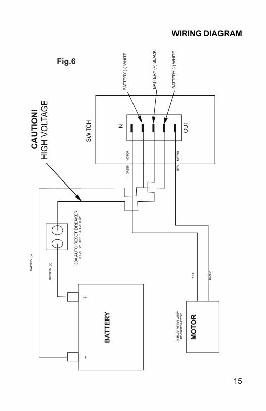
Step 1 - Attach voltmeter (or test light) leads to the negative and positiveswitch terminals on back of wall switch (See Fig. 6). Does the meterindicate 12V DC?If YES, see Step 2; if NO see Step 3.
Step 2 - If YES, at the motor, check the incoming leads to 12V DC (ifnecessary, disconnect leads at wire splices). Does meter indicate 12VDC? If YES, Motor needs to be replaced. The motor is not fieldserviceable. DO NOT ATTEMPT TO REPAIR. If NO, Inspect all wiresand connections between the wall switch and the motor. Repairconnections as necessary. Recheck as in Step 1.
Step 3 - If NO, Inspect all connections between battery and switch.Inspect 30A Auto-reset Circuit Breaker (See Fig. 6 for location).Recheck as above in Step 1.
Since there are no field serviceable parts in the motor, electricaltroubleshooting and service is limited to replacing only thosecomponents as previously outlined.
Thorough inspection of wiring and connections is the only other electricalservice that can be performed.
14
B
ATTE
RY
MO
TOR
R
ED
CH
ANG
E O
F PO
LAR
ITY
R
EVER
SES
MO
TOR
GR
EEN
MO
TOR
30A
AU
TO R
ESE
T B
REA
KER
LO
CAT
E W
ITH
IN 1
8” O
F BA
TTER
Y
SWIT
CH
BATT
ER
Y (-
) WH
ITE
BATT
ERY
(+) B
LAC
K
BATT
ERY
(-)
WH
ITE
OU
T
-
+
RED
MO
TOR
BLAC
K BATT
ERY
(-)
BATT
ERY
(+)
CA
UTI
ON
! H
IGH
VO
LTAG
E
IN
Fig.6
WIRING DIAGRAM
15

ORDERING PARTS
To assist the customer service when ordering parts, please provide thefollowing information:
1. Your Name
2. Company Name
3. Phone Number
4. Shipping Address
5. Billing Address
6. Purchase Order Number
7. Coach A. Serial # and/or VIN # B. Make C. Model
8. Part Number
9. Description
10. Quantity
Please take your coach to an authorized service center for repairs.Systems that have been modified, adjusted, repaired or augmented bya party other than an authorized service center may void any warrantyclaim with Lippert Components, Inc.
16