ELECTRIC ACTUATOR - Koei Ind Manual.pdf · ACT-U01E-4 OPERATION MANUAL ELECTRIC ACTUATOR “...
18
ACT-U01E-4 OPERATION MANUAL ELECTRIC ACTUATOR “ Unic Series “ ROTARY TYPE Unic – Z, 05 Unic – 10 Unic – 20, 40 Unic – 60, 100, 150, 200 Koei Industry Co., Ltd.
-
Upload
vuonghuong -
Category
Documents
-
view
289 -
download
0
Transcript of ELECTRIC ACTUATOR - Koei Ind Manual.pdf · ACT-U01E-4 OPERATION MANUAL ELECTRIC ACTUATOR “...
ACT-U01E-4
OPERATION MANUAL
ELECTRIC ACTUATOR
“ Unic Series “ ROTARY TYPE Unic – Z, 05 Unic – 10 Unic – 20, 40 Unic – 60, 100, 150, 200
Koei Industry Co., Ltd.
ACT-U01E-4
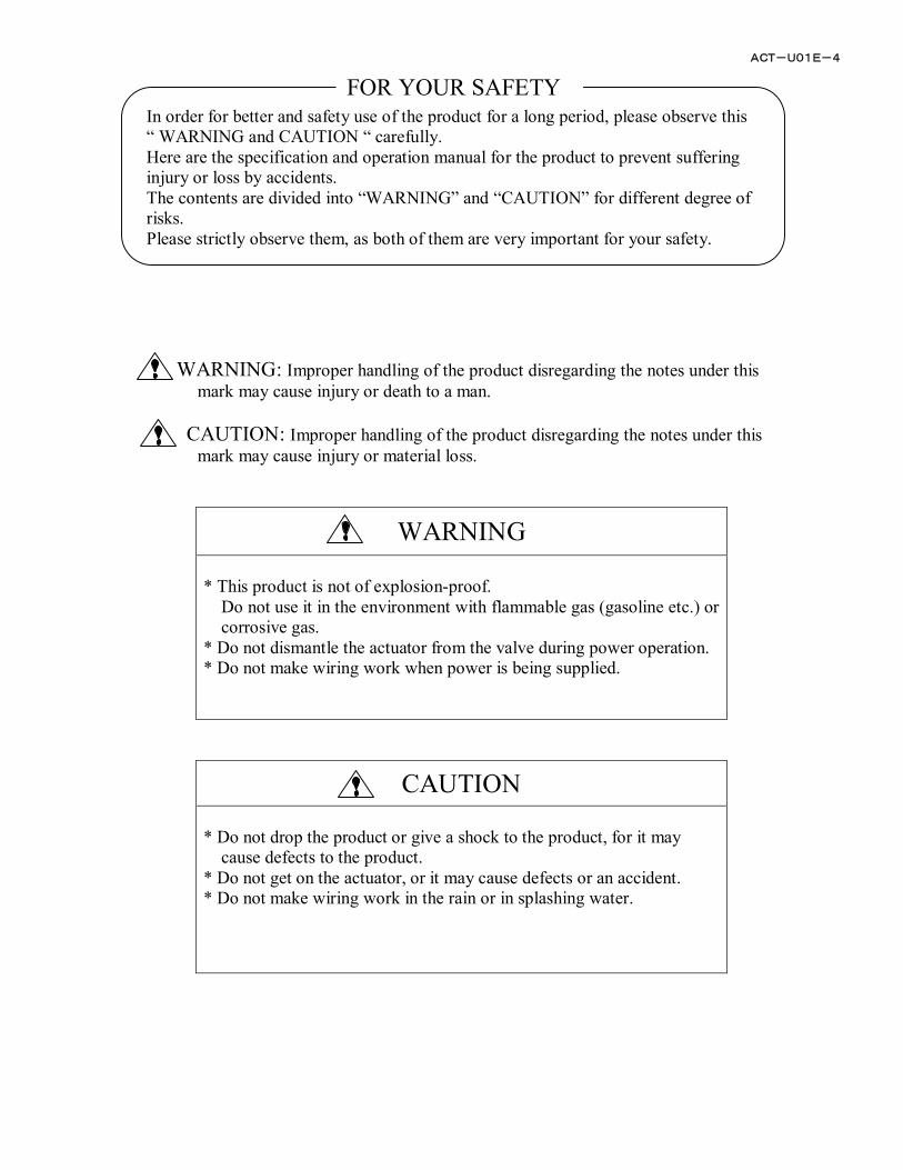
FOR YOUR SAFETY In order for better and safety use of the product for a long period, please observe this “ WARNING and CAUTION “ carefully. Here are the specification and operation manual for the product to prevent suffering injury or loss by accidents. The contents are divided into “WARNING” and “CAUTION” for different degree of risks. Please strictly observe them, as both of them are very important for your safety. WARNING: Improper handling of the product disregarding the notes under this mark may cause injury or death to a man. CAUTION: Improper handling of the product disregarding the notes under this mark may cause injury or material loss.
WARNING * This product is not of explosion-proof.
Do not use it in the environment with flammable gas (gasoline etc.) or corrosive gas.
* Do not dismantle the actuator from the valve during power operation. * Do not make wiring work when power is being supplied.
CAUTION * Do not drop the product or give a shock to the product, for it may
cause defects to the product. * Do not get on the actuator, or it may cause defects or an accident. * Do not make wiring work in the rain or in splashing water.
ACT-U01E-4
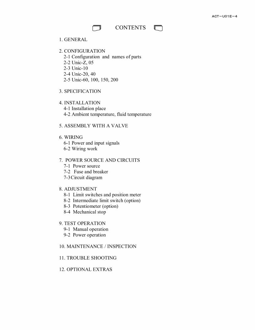
CONTENTS
1. GENERAL 2. CONFIGURATION
2-1 Configuration and names of parts 2-2 Unic-Z, 05 2-3 Unic-10 2-4 Unic-20, 40 2-5 Unic-60, 100, 150, 200
3. SPECIFICATION 4. INSTALLATION
4-1 Installation place 4-2 Ambient temperature, fluid temperature
5. ASSEMBLY WITH A VALVE 6. WIRING
6-1 Power and input signals 6-2 Wiring work
7. POWER SOURCE AND CIRCUITS
7-1 Power source 7-2 Fuse and breaker 7-3 Circuit diagram
8. ADJUSTMENT
8-1 Limit switches and position meter 8-2 Intermediate limit switch (option) 8-3 Potentiometer (option) 8-4 Mechanical stop
9. TEST OPERATION
9-1 Manual operation 9-2 Power operation
10. MAINTENANCE / INSPECTION 11. TROUBLE SHOOTING 12. OPTIONAL EXTRAS
ACT-U01E-4
1
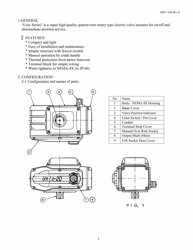
1.GENERAL
“Unic Series” is a super high quality quarter-turn rotary type electric valve actuator for on/off and intermediate position service.
FEATURES * Compact and light * Easy of installation and maintenance * Simple structure with fewest trouble * Manual operation by crank handle * Thermal protection from motor burn-out * Terminal block for simple wiring * Water tightness to NEMA-4X (to IP-66)
2. CONFIGURATION
2-1 Configuration and names of parts
No Name 1 Body: NEMA 4X Housing 2 Gear Cover 3 Valve Position Indicator 4 Limit Switch / Pot Cover 5 Conduit 6 Terminal Strip Cover 7 Manual Over Ride Socket 8 Output Shaft (Male) 9 O/R Socket Dust Cover
9
ACT-U01E-4
2
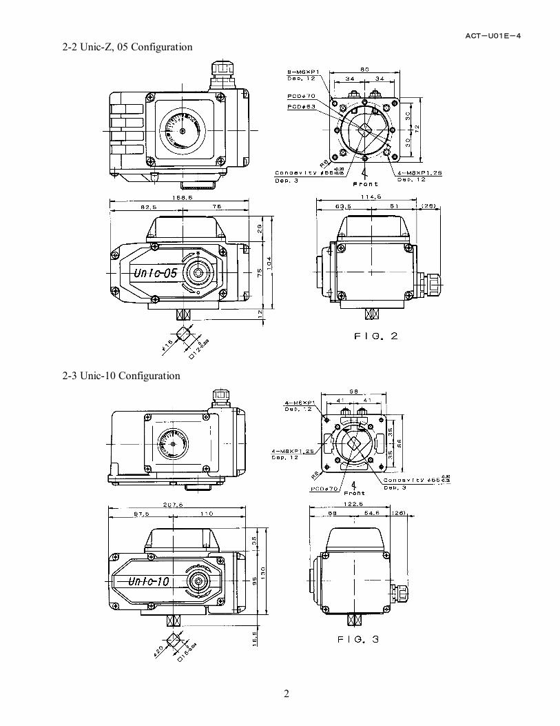
2-2 Unic-Z, 05 Configuration
2-3 Unic-10 Configuration
ACT-U01E-4
3
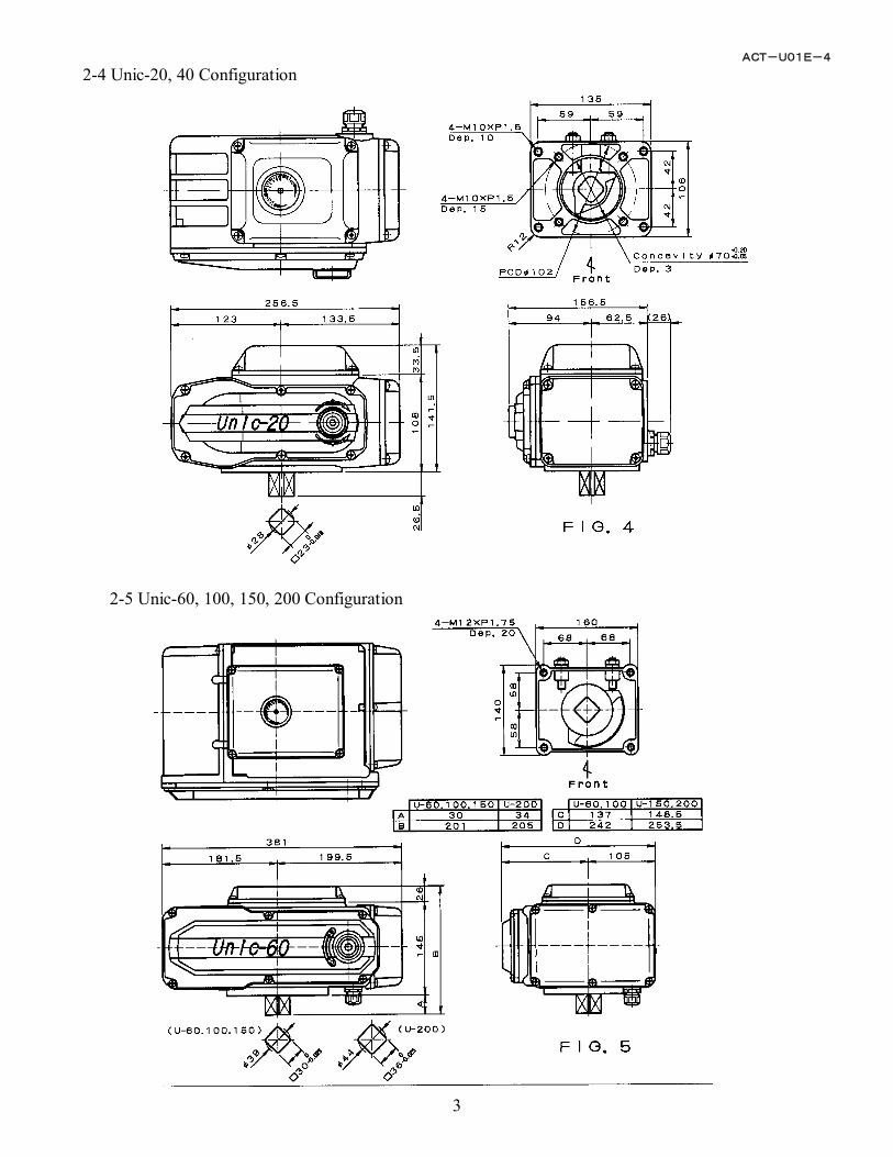
2-4 Unic-20, 40 Configuration
2-5 Unic-60, 100, 150, 200 Configuration
ACT-U01E-4
4
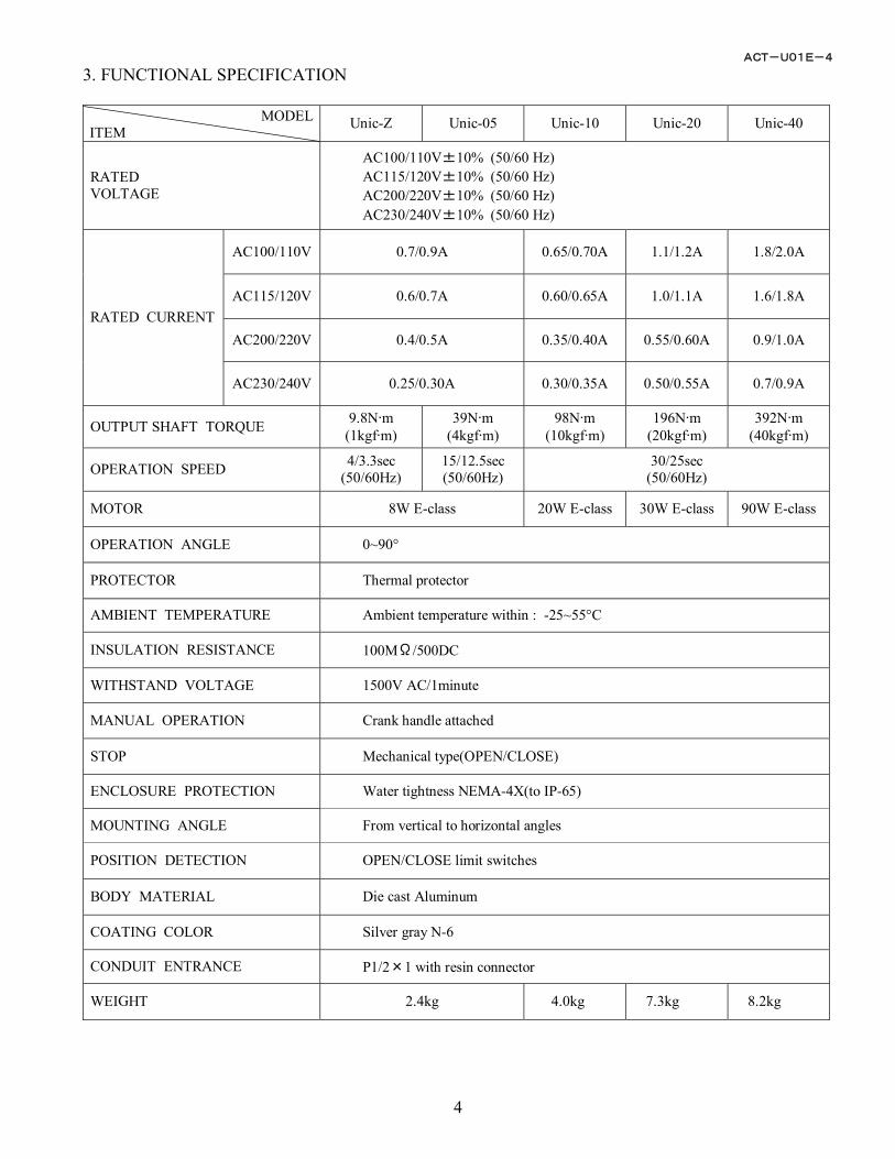
3. FUNCTIONAL SPECIFICATION
MODEL ITEM Unic-Z Unic-05 Unic-10 Unic-20 Unic-40
RATED VOLTAGE
AC100/110V±10% (50/60 Hz) AC115/120V±10% (50/60 Hz) AC200/220V±10% (50/60 Hz) AC230/240V±10% (50/60 Hz)
AC100/110V 0.7/0.9A 0.65/0.70A 1.1/1.2A 1.8/2.0A
AC115/120V 0.6/0.7A 0.60/0.65A 1.0/1.1A 1.6/1.8A
AC200/220V 0.4/0.5A 0.35/0.40A 0.55/0.60A 0.9/1.0A RATED CURRENT
AC230/240V 0.25/0.30A 0.30/0.35A 0.50/0.55A 0.7/0.9A
OUTPUT SHAFT TORQUE 9.8N·m (1kgf·m)
39N·m (4kgf·m)
98N·m (10kgf·m)
196N·m (20kgf·m)
392N·m (40kgf·m)
OPERATION SPEED 4/3.3sec (50/60Hz)
15/12.5sec (50/60Hz)
30/25sec (50/60Hz)
MOTOR 8W E-class 20W E-class 30W E-class 90W E-class
OPERATION ANGLE 0~90°
PROTECTOR Thermal protector
AMBIENT TEMPERATURE Ambient temperature within : -25~55°C
INSULATION RESISTANCE 100MΩ/500DC
WITHSTAND VOLTAGE 1500V AC/1minute
MANUAL OPERATION Crank handle attached
STOP Mechanical type(OPEN/CLOSE)
ENCLOSURE PROTECTION Water tightness NEMA-4X(to IP-65)
MOUNTING ANGLE From vertical to horizontal angles
POSITION DETECTION OPEN/CLOSE limit switches
BODY MATERIAL Die cast Aluminum
COATING COLOR Silver gray N-6
CONDUIT ENTRANCE P1/2×1 with resin connector
WEIGHT 2.4kg 4.0kg 7.3kg 8.2kg
ACT-U01E-4
5
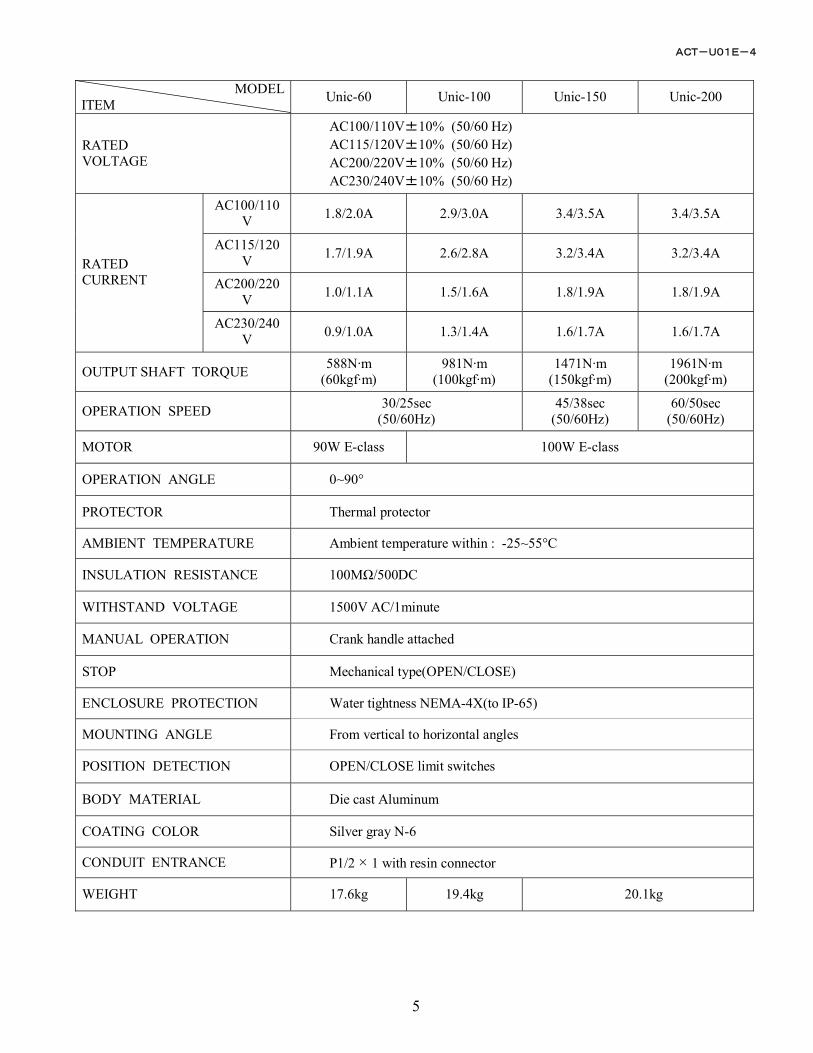
MODEL
ITEM Unic-60 Unic-100 Unic-150 Unic-200
RATED VOLTAGE
AC100/110V±10% (50/60 Hz) AC115/120V±10% (50/60 Hz) AC200/220V±10% (50/60 Hz) AC230/240V±10% (50/60 Hz)
AC100/110V 1.8/2.0A 2.9/3.0A 3.4/3.5A 3.4/3.5A
AC115/120V 1.7/1.9A 2.6/2.8A 3.2/3.4A 3.2/3.4A
AC200/220V 1.0/1.1A 1.5/1.6A 1.8/1.9A 1.8/1.9A
RATED CURRENT
AC230/240V 0.9/1.0A 1.3/1.4A 1.6/1.7A 1.6/1.7A
OUTPUT SHAFT TORQUE 588N·m (60kgf·m)
981N·m (100kgf·m)
1471N·m (150kgf·m)
1961N·m (200kgf·m)
OPERATION SPEED 30/25sec (50/60Hz)
45/38sec (50/60Hz)
60/50sec (50/60Hz)
MOTOR 90W E-class 100W E-class
OPERATION ANGLE 0~90°
PROTECTOR Thermal protector
AMBIENT TEMPERATURE Ambient temperature within : -25~55°C
INSULATION RESISTANCE 100MΩ/500DC
WITHSTAND VOLTAGE 1500V AC/1minute
MANUAL OPERATION Crank handle attached
STOP Mechanical type(OPEN/CLOSE)
ENCLOSURE PROTECTION Water tightness NEMA-4X(to IP-65)
MOUNTING ANGLE From vertical to horizontal angles
POSITION DETECTION OPEN/CLOSE limit switches
BODY MATERIAL Die cast Aluminum
COATING COLOR Silver gray N-6
CONDUIT ENTRANCE P1/2 × 1 with resin connector
WEIGHT 17.6kg 19.4kg 20.1kg
ACT-U01E-4
6
CAUTION ON ENVIRONMENTAL INSTALLATION CONDITIONS 4.INSTALLATION
4-1 Installation Caution on indoor installation * The actuators are not of explosion-proof type. Do not install in a hazardous place. * Cover whole the unit, if it is installed at a place where water or materials are splashing. * Reserve a space for manual maintenance work.
Caution on outdoor installation * Shade the unit from direct sunlight, that may cause overheat and defect to the unit. * Reserve a space for manual maintenance work.
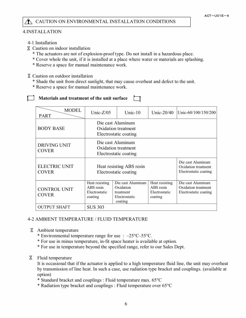
Materials and treatment of the unit surface
MODEL PART
Unic-Z/05 Unic-10 Unic-20/40 Unic-60/100/150/200
BODY BASE Die cast Aluminum Oxidation treatment Electrostatic coating
DRIVING UNIT COVER
Die cast Aluminum Oxidation treatment Electrostatic coating
ELECTRIC UNIT COVER
Heat resisting ABS resin Electrostatic coating
Die cast Aluminum Oxidation treatment Electrostatic coating
CONTROL UNIT COVER
Heat resisting ABS resin Electrostatic coating
Die cast AluminumOxidation treatment Electrostatic coating
Heat resisting ABS resin Electrostatic coating
Die cast Aluminum Oxidation treatment Electrostatic coating
OUTPUT SHAFT SUS 303
4-2 AMBIENT TEMPERATURE / FLUID TEMPERATURE
Ambient temperature * Environmental temperature range for use : –25°C~55°C. * For use in minus temperature, in-fit space heater is available at option. * For use in temperature beyond the specified range, refer to our Sales Dept.
Fluid temperature It is occasional that if the actuator is applied to a high temperature fluid line, the unit may overheat by transmission of line heat. In such a case, use radiation type bracket and couplings. (available at option) * Standard bracket and couplings : Fluid temperature max. 65°C * Radiation type bracket and couplings : Fluid temperature over 65°C
ACT-U01E-4
7
CAUTION ON WIRING WORK
CAUTION ON ASSEMBLY WITH A VALVE
O-ring 1/2”NPT Seal
Seal Tight Device
Actuator body
Cable outer diameter φ9~φ11
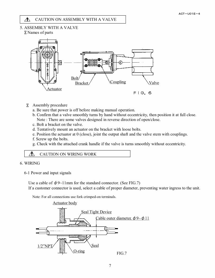
5. ASSEMBLY WITH A VALVE
Names of parts
Assembly procedure a. Be sure that power is off before making manual operation. b. Confirm that a valve smoothly turns by hand without eccentricity, then position it at full close.
Note : There are some valves designed in reverse direction of open/close. c. Bolt a bracket on the valve. d. Tentatively mount an actuator on the bracket with loose bolts. e. Position the actuator at 0 (close), joint the output shaft and the valve stem with couplings. f. Screw up the bolts. g. Check with the attached crank handle if the valve is turns smoothly without eccentricity.
6. WIRING
6-1 Power and input signals
Use a cable of φ9~11mm for the standard connector. (See FIG.7) If a customer connector is used, select a cable of proper diameter, preventing water ingress to the unit.
Note: For all connections use fork crimped-on terminals.
Actuator
Bolt Bracket Coupling Valve
FIG.7
ACT-U01E-4
8
CAUTION ON USE
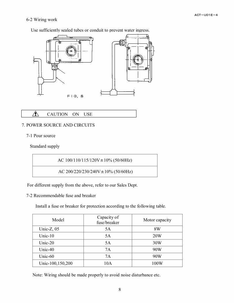
6-2 Wiring work
Use sufficiently sealed tubes or conduit to prevent water ingress. 7. POWER SOURCE AND CIRCUITS
7-1 Pour source Standard supply
AC 100/110/115/120V±10% (50/60Hz)
AC 200/220/230/240V±10% (50/60Hz)
For different supply from the above, refer to our Sales Dept.
7-2 Recommendable fuse and breaker
Install a fuse or breaker for protection according to the following table.
Model Capacity of fuse/breaker Motor capacity
Unic-Z, 05 5A 8W Unic-10 5A 20W Unic-20 5A 30W Unic-40 7A 90W Unic-60 7A 90W Unic-100,150,200 10A 100W
Note: Wiring should be made properly to avoid noise disturbance etc.
ACT-U01E-4
9
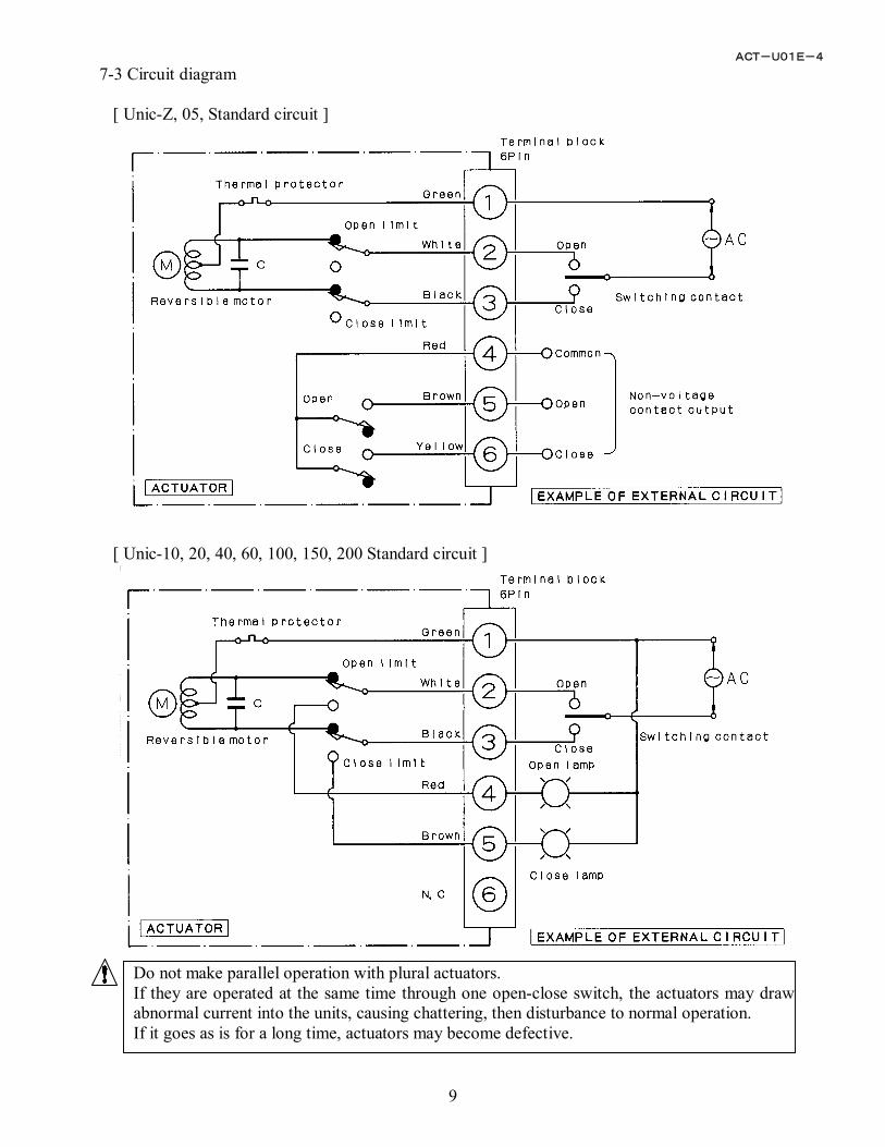
7-3 Circuit diagram
[ Unic-Z, 05, Standard circuit ]
[ Unic-10, 20, 40, 60, 100, 150, 200 Standard circuit ]
Do not make parallel operation with plural actuators. If they are operated at the same time through one open-close switch, the actuators may draw abnormal current into the units, causing chattering, then disturbance to normal operation. If it goes as is for a long time, actuators may become defective.
ACT-U01E-4
10
Confirm that power is OFF before making manual operation
Valve Position Indicator
Dog Setting Nut
Limit Dog
Output Shaft
Limit Dog
Valve Position Indicator
Socket Set Screw
Output Shaft
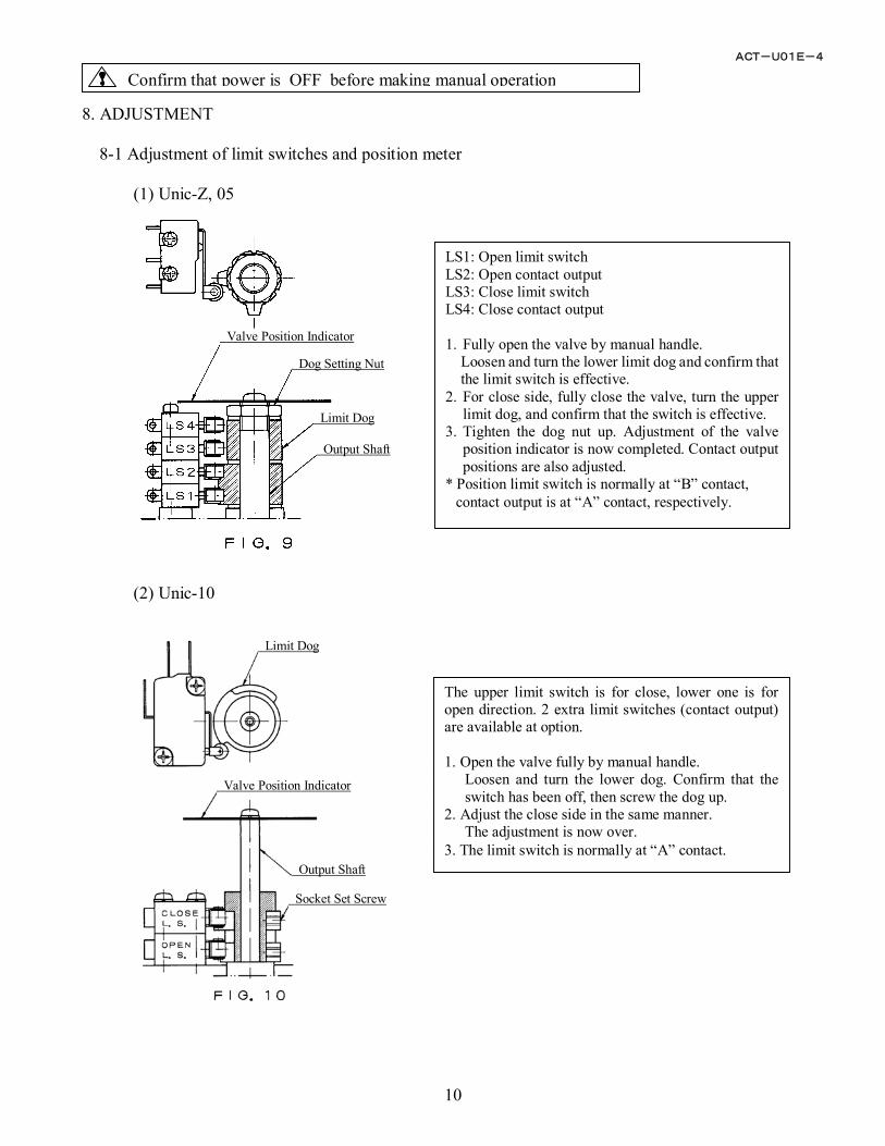
8. ADJUSTMENT
8-1 Adjustment of limit switches and position meter
(1) Unic-Z, 05
(2) Unic-10
LS1: Open limit switchLS2: Open contact output LS3: Close limit switch LS4: Close contact output 1. Fully open the valve by manual handle.
Loosen and turn the lower limit dog and confirm that the limit switch is effective.
2. For close side, fully close the valve, turn the upper limit dog, and confirm that the switch is effective.
3. Tighten the dog nut up. Adjustment of the valve position indicator is now completed. Contact output positions are also adjusted.
* Position limit switch is normally at “B” contact, contact output is at “A” contact, respectively.
The upper limit switch is for close, lower one is foropen direction. 2 extra limit switches (contact output)are available at option. 1. Open the valve fully by manual handle.
Loosen and turn the lower dog. Confirm that theswitch has been off, then screw the dog up.
2. Adjust the close side in the same manner. The adjustment is now over.
3. The limit switch is normally at “A” contact.
ACT-U01E-4
11
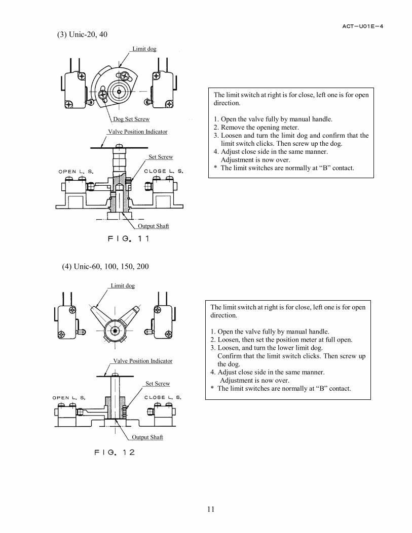
(3) Unic-20, 40
(4) Unic-60, 100, 150, 200
The limit switch at right is for close, left one is for open direction. 1. Open the valve fully by manual handle. 2. Remove the opening meter. 3. Loosen and turn the limit dog and confirm that the
limit switch clicks. Then screw up the dog. 4. Adjust close side in the same manner.
Adjustment is now over. * The limit switches are normally at “B” contact.
The limit switch at right is for close, left one is for open direction. 1. Open the valve fully by manual handle. 2. Loosen, then set the position meter at full open. 3. Loosen, and turn the lower limit dog.
Confirm that the limit switch clicks. Then screw up the dog.
4. Adjust close side in the same manner. Adjustment is now over.
* The limit switches are normally at “B” contact.
Limit dog
Dog Set Screw
Valve Position Indicator
Set Screw
Output Shaft
Limit dog
Valve Position Indicator
Set Screw
Output Shaft
ACT-U01E-4
12
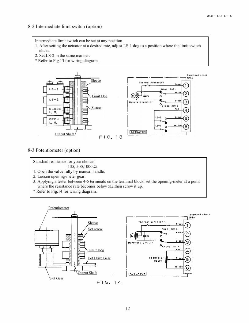
Potentiometer
Sleeve
Set screw
Limit Dog
Pot Drive Gear
Output Shaft Pot Gear
8-2 Intermediate limit switch (option)
8-3 Potentiometer (option)
Intermediate limit switch can be set at any position.1. After setting the actuator at a desired rate, adjust LS-1 dog to a position where the limit switch
clicks. 2. Set LS-2 in the same manner. * Refer to Fig.13 for wiring diagram.
Standard resistance for your choice: 135, 500,1000 Ω
1. Open the valve fully by manual handle. 2. Loosen opening-meter gear. 3. Applying a tester between 4-5 terminals on the terminal block, set the opening-meter at a point
where the resistance rate becomes below 5Ω,then screw it up. * Refer to Fig.14 for wiring diagram.
Sleeve
Limit Dog
Spacer
Output Shaft
ACT-U01E-4
13
CAUTION
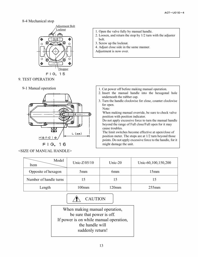
8-4 Mechanical stop
9. TEST OPERATION
9-1 Manual operation <SIZE OF MANUAL HANDLE>
Model Item Unic-Z/05/10 Unic-20 Unic-60,100,150,200
Opposite of hexagon 5mm 6mm 15mm
Number of handle turns 15 15 15
Length 100mm 120mm 255mm
1. Open the valve fully by manual handle. 2. Loosen, and return the stop by 1/2 turn with the adjuster
bolt. 3. Screw up the locknut. 4. Adjust close side in the same manner. Adjustment is now over.
1. Cut power off before making manual operation.2. Insert the manual handle into the hexagonal hole
underneath the rubber cap. 3. Turn the handle clockwise for close, counter clockwise
for open. Note: When making manual override, be sure to check valve position with position indicator. Do not apply excessive force to turn the manual handle beyond the range of Full close/Full open for it may cause troubles. The limit switches become effective at open/close of position meter. The stops are at 1/2 turn beyond those points. Do not apply excessive force to the handle, for it might damage the unit.
When making manual operation, be sure that power is off.
If power is on while manual operation, the handle will
suddenly return!
Adjustment Bolt Locknut
Stopper
ACT-U01E-4
14
9-2 Power operation
Before making power operation:
* Confirm that the indication on the position meter and the valve opening are matching each other. * Confirm that the circuits are properly wired, also that the unit operates in correct direction with
external switches. 10. MAINTENANCE, INSPECTION
Lubrication As the major parts of the products are lubricated with long life di-sulfate molybdenum grease (MoS2) before shipment, re-lubrication is in principle not required. Inspection When re-starting operation after a long period of rest, make the following confirmation. * Cut power off, confirm by manual operation that valve moves smoothly without eccentricity. * Open body cover and check if there is no condensation inside the unit, also no problem on wiring. Note: After checking, secure the cover to prevent water ingress.
ACT-U01E-4
15
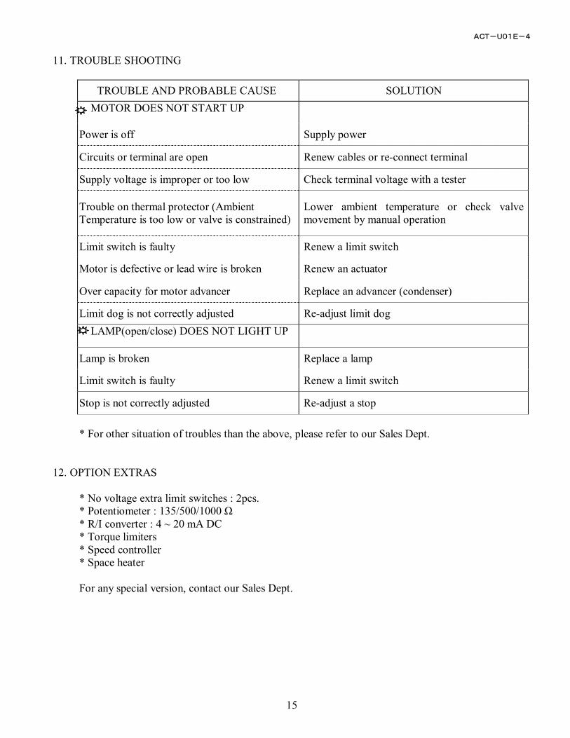
11. TROUBLE SHOOTING
TROUBLE AND PROBABLE CAUSE SOLUTION MOTOR DOES NOT START UP
Power is off Supply power
Circuits or terminal are open Renew cables or re-connect terminal
Supply voltage is improper or too low Check terminal voltage with a tester
Trouble on thermal protector (Ambient Temperature is too low or valve is constrained)
Lower ambient temperature or check valve movement by manual operation
Limit switch is faulty Renew a limit switch
Motor is defective or lead wire is broken Renew an actuator
Over capacity for motor advancer Replace an advancer (condenser)
Limit dog is not correctly adjusted Re-adjust limit dog LAMP(open/close) DOES NOT LIGHT UP
Lamp is broken Replace a lamp
Limit switch is faulty Renew a limit switch
Stop is not correctly adjusted Re-adjust a stop * For other situation of troubles than the above, please refer to our Sales Dept.
12. OPTION EXTRAS
* No voltage extra limit switches : 2pcs. * Potentiometer : 135/500/1000 Ω * R/I converter : 4 ~ 20 mA DC * Torque limiters * Speed controller * Space heater For any special version, contact our Sales Dept.