ELECTE 1) - apps.dtic.mil · Form Approved REPORT DOCUMENTATION PAGE Fo.m Apo4-018 Public reporting...
154
AD-A266 984 WL-TR-93-2047 ADVANCED COOLING FOR HIGH POWER ELECTRIC ACTUATORS Michael G. Schneider Timothy J. Bland DTIC ELECTE Sundstrand Corporation JUL 13 1993 P.O. Box 7002 1) Rockford, IL 61125-7002 A January 1993 Interim Report for January 1992 to September 1992 APPROVED FOR PUBLIC RELEASE; DISTRIBUTION UNLIMITED AERO PROPULSION AND POWER DIRECTORATE WRIGHT LABORATORY AIR FORCE MATERI EL COMMAND WRIGHT-PATTERSON AFB OH 45433-7650 93-15784 //t/h Ll/l//i•l/ll/6glt,• '
Transcript of ELECTE 1) - apps.dtic.mil · Form Approved REPORT DOCUMENTATION PAGE Fo.m Apo4-018 Public reporting...
AD-A266 984
WL-TR-93-2047
ADVANCED COOLING FOR HIGHPOWER ELECTRIC ACTUATORS
Michael G. Schneider
Timothy J. Bland DTICELECTE
Sundstrand Corporation JUL 13 1993P.O. Box 7002 1)Rockford, IL 61125-7002 A
January 1993
Interim Report for January 1992 to September 1992
APPROVED FOR PUBLIC RELEASE; DISTRIBUTION UNLIMITED
AERO PROPULSION AND POWER DIRECTORATEWRIGHT LABORATORYAIR FORCE MATERI EL COMMANDWRIGHT-PATTERSON AFB OH 45433-7650 93-15784
//t/h Ll/l//i•l/ll/6glt,• '
NOTICE
When Government drawings, specifications, or other data are used for
any purpose other than in connection with a definitely Government-relatedprocurement, the United States Government incurs no responsibility or any
obligation whatsoever. The fact that the government may have formulated or
in any way supplied the said drawings, specifications, or other data, is not
to be regarded by implication, or otherwise in any manner construed, as
licensing the holder, or any other person or corporation; or as conveying
any rights or permission to manufacture, use, or sell any patented inventionthat may in any way be related thereto.
This report is releasable to the National Technical Information Service
(NTIS). At NTIS, it will be available to the general public, includingforeign nations.
This technical report has been reviewed and is approved for publica-
tion.
Micheal J. -Mrgan ."err/E. BeamProject Engineer Section Chief
Thermal Technology Section Thermal Technology SectionPower Technology Branch
MICHAEL D. BRAYDICH, U CosAAF
Deputy ChiefAesospMace Iower Diwision
Aero PropOisiOn & Vot,, u11gslora&
If your address has changed, if you wish to be removed from our mailing
list, or if the addressee is no longer employed by your organization pleasenotify WL/POOS-J WPAFB, OH 45433- 7251 to help us maintain a currentmailing list.
Copies of this report should not be returned unless return is required by
security considerations, contractual obligations, or notice on a specificdocument.
Form Approved
REPORT DOCUMENTATION PAGE Fo.m Apo4-018
Public reporting burden for this collection of information s estimatýd to average I hour per response, including the time for reiewming instructions, searching existing data sources.gathering and maintaining the data needed, and completing and reviewing the collection of information Send comments regarding this burden estimate or any other aspect of thiscollection of informatlon, including suggestions for reducing this burden to Washington Headquarters Services. Directorate for information Operations and Reports. 1215 JeffersonsDavis Hghwlv, Suite 1204. Arlington. VA 22202-4302. and to the Office of Management and Budget, Paperwork Reduction Project (0704-0188), Washington. DC 20503.
1. AGENCY USE ONLY (Leave blank) 2. REPORT DATE 3. REPORT TYPE AND DATES COVERED
January 1993 Interim Jan 92 to Sep 924. TITLE AND SUBTITLE S. FUNDING NUMBERS
Advanced Cooling for High Power Electric C-F33615-91-C-2139Actuators PE-62203F
PR-3145"6. AUTHOR(S) TA-29
Michael G. Schneider WU-14Timothy J. Bland
7. PERFORMING ORGANIZATION NAME(S) AND ADDRESS(ES) B. PERFORMING ORGANIZATION
Sundstrand Corp. REPORT NUMBER
PO Box 7002Rockford IL 61125-7002
9. SPONSORING /MONITORING AGENCY NAME(S) AND ADrqESS(ES) 10. SPONSORING/MONITORINGAero Propulsion and Power Directorate AGENCY REPORT NUMBERWright Laboratory WL-TR-93-2047Air Force Materi..el CommandWright-Pattersor AFB OH 45433-7650
"11. SUPPLEMENTARY NOTES
12a. DISTRIBUTION /AVAILABILITY STATEMENT 12b. DISTRIBUTION CODE
Approved for Public Release; Distribution Unlimited
13. ABSTRACT (Maximum 200 words)
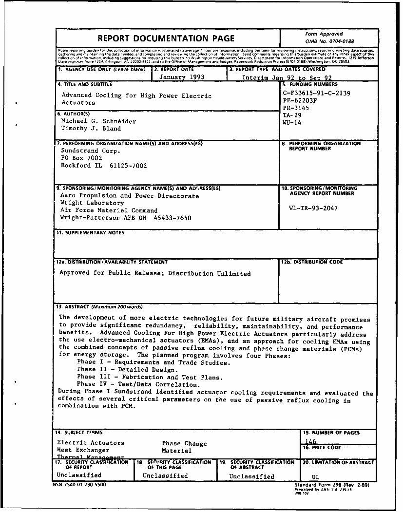
The development of more electric technologies for future military aircraft promisesto provide significant redundancy, reliability, maintainability, and performancebenefits. Advanced Cooling For High Power Electric Actuators particularly addressthe use electro-mechanical actuators (EMAs), and an approach for cooling EMAs usingthe combined concepts of passive reflux cooling and phase change materials (PCMs)for energy storage. The planned program involves four Phases:
Phase I - Requirements and Trade Studies.rhase II - Detailed Design.Phase III - Fabrication and Test Plans.Phase IV - Test/Data Correlation.
During Phase I Sundstrand identified actuator cooling requirements and evaluated theeffects of several critical parameters on the use of passive reflux cooling incombination with PCM.
14. SUBJECT TFRMS IS. NUMBER OF PAGES
Electric Actuators Phase Change 146Heat Exchanger Material 16 PRICE CODEThnrn• I Mann fan•=.nn -_________-________
17. SECURITY CLASSIFICATION 16 sPIIqlTY CLASSIFICATION 19. SECURITY CLASSIFICATION 20. LIMITATION OF ABSTRACTOF REPORT OF THIS PAGE OF ABSTRACT
Unclassified Unclassified Unclassified ULNSN 7540-01-280-5500 Standard Form 298 (Rev 2-89)
Prescribed by ANSI Std 139.-1296-102
TABLE OF CONTENTS
PAGE NUMBER
1.0 INTRODUCTION 11.1 Background 11.2 EMA Passive Cooling Approach 1
2.0 SPECIFICATIONS 8
3.0 DEMONSTRATION REFLUX COOLER DESIGN SUMMARY 13
4.0 ANALYTICAL METHODS 144.1 SINDA Model Description 144.2 Model Inputs/Defaults 144.3 Correlations 20
5.0 TRADE STUDIES 235.1 Actuator Comparison 235.2 Steady State Analysis 23
5.2.1 Geometry/Design Considerations5.2.2 Mission Considerations5.2.3 Type of Motor
5.3 Motor Comparison 535.4 Transient Analysis 57
5.4.1 Frequency Response5.4.2 Combat Phase5.4.3 Typical Combat Mission
5.5 Working Fluid Comparison 775.6 Phase Change Material Comparison 875.7 Demonstration Motor Selection 905.8 Manufacturing Approach 92
6.0 CONCLUSIONS 94
7.0 RECOMMENDATIONS 95
8.0 REFERENCES 96
APPENDIX A - FIGURES IN BRITISH UNITS Accesion For 98NTIS CRA&MDTIC TAB UU., .dIouu ,ed cJi ;tfficjtion
ByDi~t"ibijfion
Availabiltty Codes
Avail zir~djurDist Special
iii111

LIST OF FIGURES
1.1 Thermosyphon Concept 2
1.2 Reflux Cooler in Normal Operation 4
1.3 Reflux Cooler in Inverted Operation 5
1.4 Effect of PCM on Reflux Temperature 6
2.1 Typical EMA Mission Duty Cycle 9
2.2 PC Cycles, Frequency, System Pressure vs. Phase 10
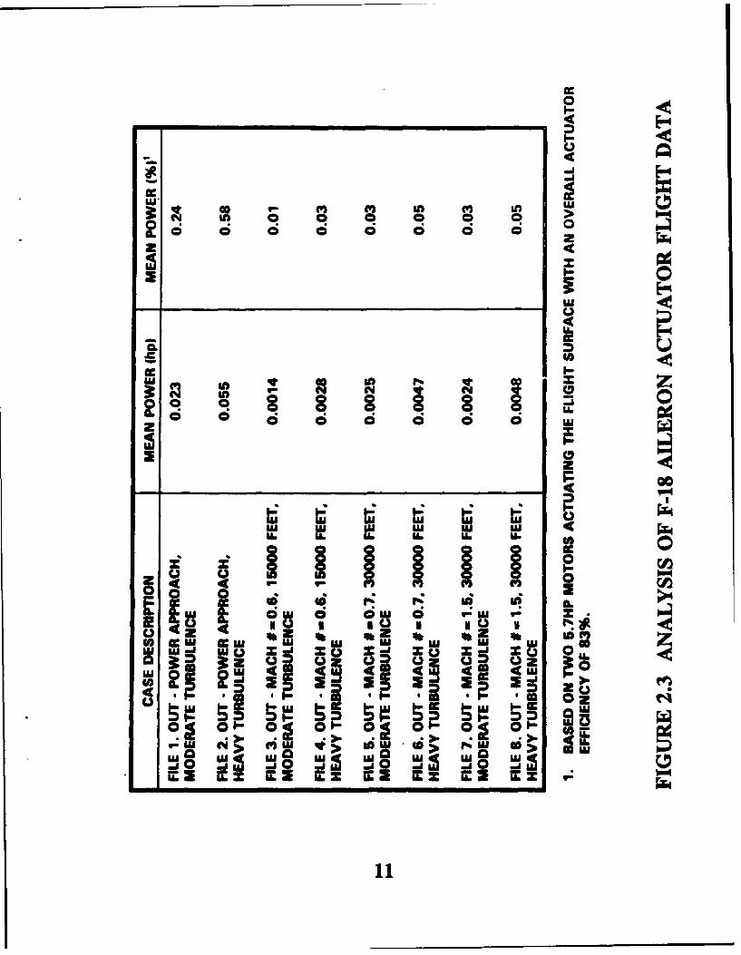
2.3 Analysis of F-18 Aileron Actuator Flight Data 11
2.4 Worne Case EMA Mission Duty Cycle 12
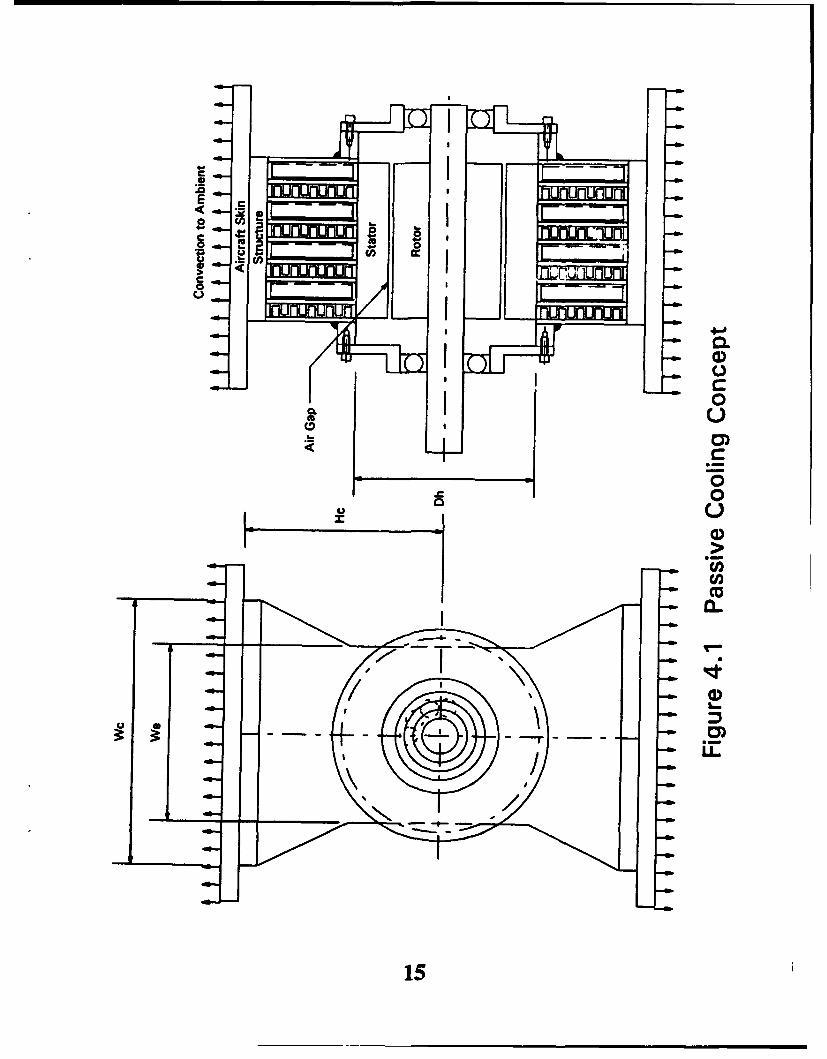
4.1 Passive Cooling Concept 15
4.2 SINDA Model Schematic 16
4.3 SINDA Models Inputs/Defaults 17
18
4.4 Motor Lous Distributions (Percentage of Total Losm) 19
5.1 Actuator Comparison 24
5.2 Advanced Actuator Cooling - Steady State Temperature vs Condenser Width Parameter 25
5.3 Advanced Actuator Cooling - Steady State Temp. Difference vs Condenser Width Parameter 26
5.4 Advanced Actuator Cooling - Steady State Temperature vs Evaporator Width Parameter 27
5.5 Advanced Actuator Cooling - Steady State Temp. Differences vs Evaporator Width Parameter 28
5.6 Advanced Actuator Cooling - Steady State Temperature vs Cooler Height Parameter 29
5.7 Advanced Actuator Cooling - Steady State Temp. Differencs vs Cooler Height Parameter 30
5.8 Advanced Actuator Cooling - Steady State Temperature vs Fin Count 31
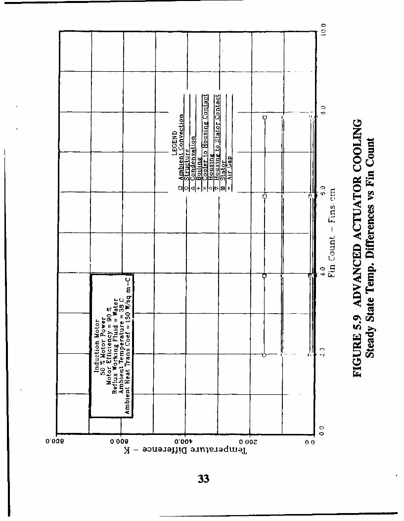
5.9 Advanced Actuator Cooling - Steady State Temp. Differences vs Fin Count 32
5.10 Advanced Actuator Cooling - Steady State Temp vs Ambient Heat Transfer Coefficient 34
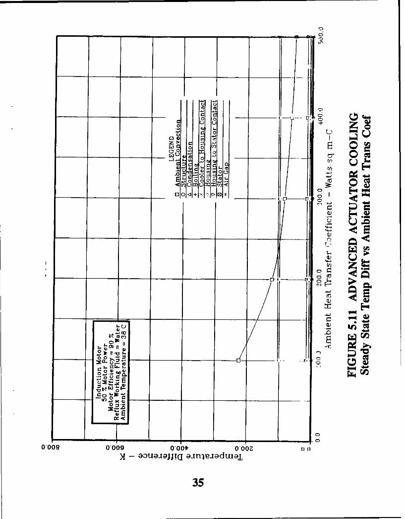
5.11 Advanced Actuator Cooling - Steady State Temp Diff vs Ambient Heat Trans Coef 35
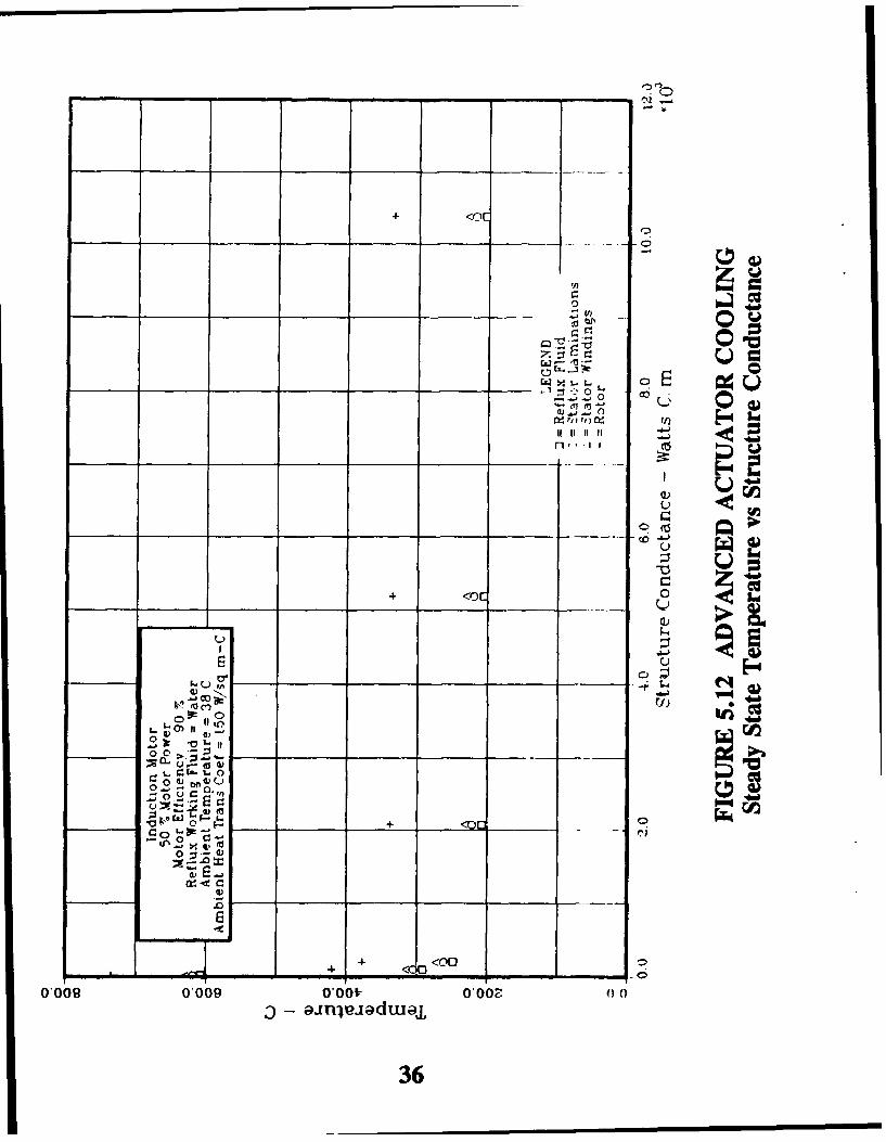
5.12 Advanced Actuator Cooling - Steady State Temperature vs Stnrcture Conductance 36
5.13 Advanced Actuator Cooling - Steady State Temp Difference vs Structure Conductance 37
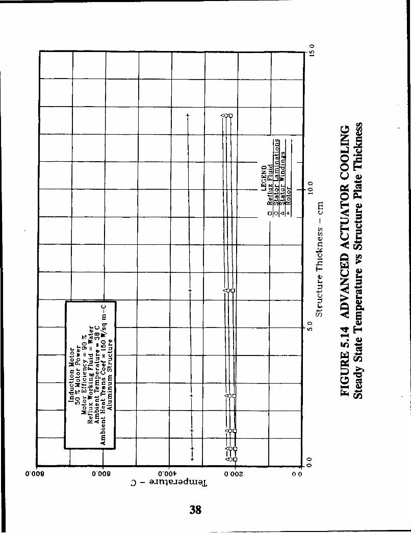
5.14 Advanced Actuator Cooling - Steady State Temperature vs Structure Plate Thickness 38
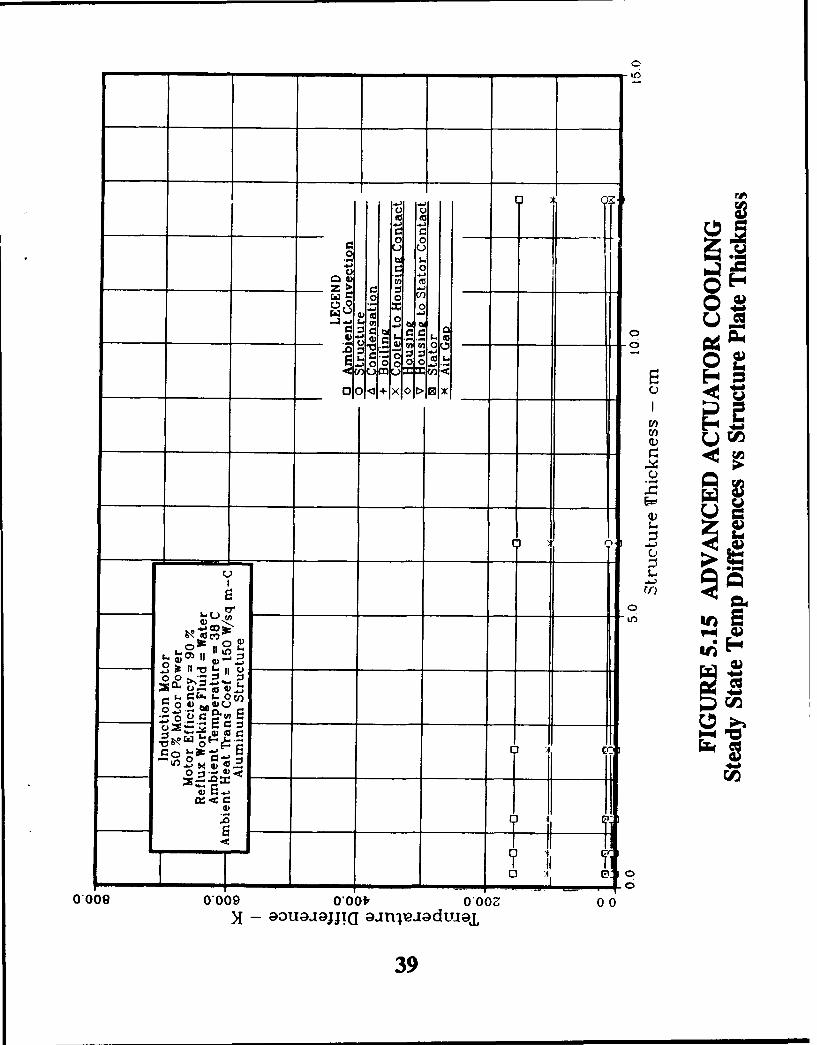
5.15 Advanced Actuator Cooling - Steady State Temp Differences vs Structure Plate Thickness 39
5.16 Advanced Actuator Cooling - Steady State Temperature vs Altitude 40
5.17 Advanced Actuator Cooling - Steady State Temp Differences vs Altitude 41
5.18 Advanced Actuator Cooling - Steady State Temperature vs Altitude 42
5.19 Advanced Actuator Cooling - Steady State Temp Differences vs Altitude 43
iv

Title Page
5.20 Advanced Actuator Cooling - Steady State Temperature vs Altitude 44
5.21 Advanced Actuator Cooling - Steady State Temp Differences vs Altitude 45
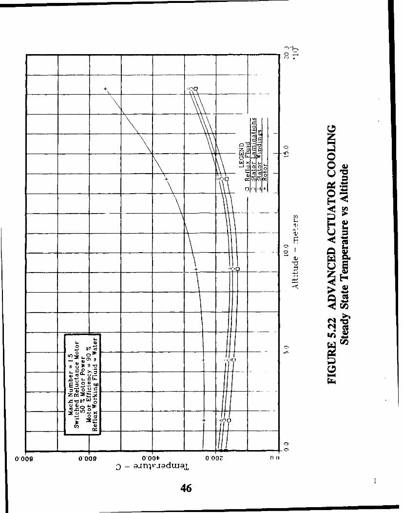
5.22 Advanced Actuator Cooling - Steady State Temperature vs Altitude 46
5.23 Advanced Actuator Cooling - Steady State Temp Differences vs Altitude 47
5.24 Advanced Actuator Cooling - Steady State Temperature vs Altitude 48
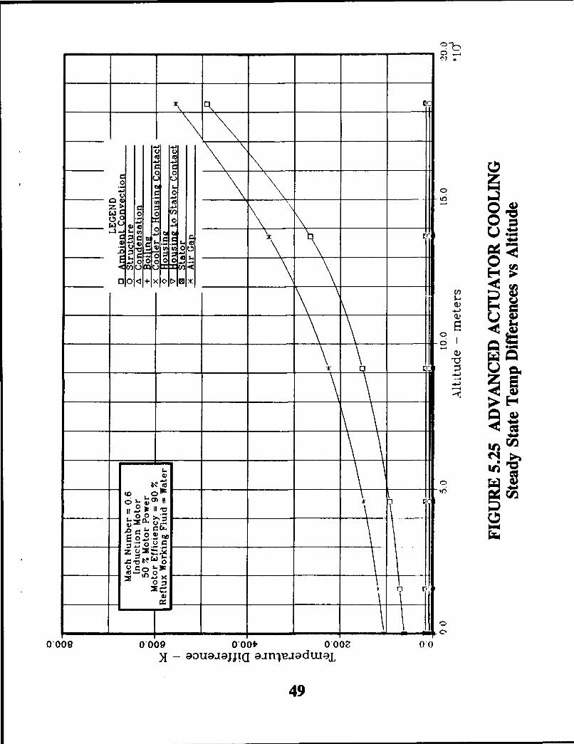
5.25 Advanced Actuator Cooling - Steady State Temp Differences vs Altitude 49
5.26 Advanced Actuator Cooling - Steady State Temperature vs Altitude 50
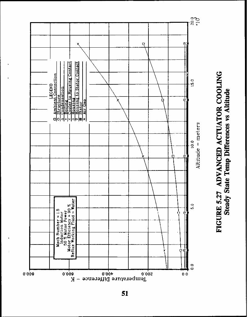
5.27 Advanced Actuator Cooling - Steady State Temp Differences vs Altitude 51
5.28 Advanced Actuator Cooling - Steady State Rotor Temperature vs Altitude 52
5.29 Electric Motor Comparison 54
5.30 Advanced Actuator Cooling - Frequency Response-Motor Power vs Time 58
5.31 Advanced Actuator Cooling - Frequency Response-Motor Power vs Time 59
5. 2 Advanced Actuator Cooling - Frequency Response-Temperature vs Time 60
5.33 Advanced Actuator Cooling - Frequency Response-Temperature vs Time 61
5.34 Advanced Actuator Cooling - Frequency Response-Temperature vs Time 62
5.35 Advanced Actuator Cooling - Frequency Response-Temperature vs Time 63
5.36 Advanced Actuator Cooling - Frequency Response 65
5.37 Advanced Actuator Cooling - Frequency Response 66
5.38 Advanced Actuator Cooling - Actuator Motor Power vs Time 67
5.39 Advanced Actuator Cooling - Temperature vs Time 68
5.40 Advanced Actuator Cooling - Temperature vs Time 69
5.41 Advanced Actuator Cooling - PCM Liquid Mass Fraction vs Time 70
5.42 Advanced Actuator Cooling - Temperature vs Time 71
5.43 Advanced Actuator Cooling - Temperature vs Time 72
5.44 Advanced Actuator Cooling - PCM Liquid Mass Fraction vs Time 73
5.45 Advanced Actuator Cooling - Temperature vs Time 74
5.46 Advanced Actuator Cooling - Temperature vs Time 75
5.47 Advanced Actuator Cooling - PCM Liquid Mass Fraction vs Time 76
5.48 Advanced Actuator Cooling - Temperature vs Time 78
5.49 Advanced Actuator Cooling - Temperature vs Time 79
5.50 Advanced Actuator Cooling - Temperature vs Time 80
5.51 Advanced Actuator Cooling - Temperature vs Time 81
5.52 Advanced Actuator Cooling - Temperature vs Time 82
V
No. NO-.
5.53 Advanced Actuator Cooling - Temperature vs Time 83
5.54 Reflux Working Fluids Comparison 85
5.55 Advanced Actuator Cooling - Fluids Comparison 86
885.56 Candidate PCMs 89
5.57 Electric Motor Comparison 91
5.58 Advanced Actuator Cooling - Passive Cooling concept 93
A,.1 Advanced Actuator cooling - Steady State Temperature vs Condenser Width Parameter 9
A.2 Advanced Actuator Cooling - Steady State Temp. Diffiemncen vs Condenser Width Parameter 100
A.3 Advanced Actuator cooling - Steady State Temperature vs Evaporfator Width Parameter 101
A.4 Advanced Actuator Cooling - Steady State Temp. Differeme vs Evaporator Width Parameter 102
A.5 Advanced Actuator Cooling - Steady State Temperature vs Cooler Height Parameter 103
A.6 Advanced Actuator Cooling - Steady Sttec Temp. Differences vs Cooler Height Parameter 104
A.7 Advanced Actuator Cooling - Steady State Temperature vs Fin Count 105
A.8 Advanced Actuator Cooling - Steady State Temp. Differences vs Fin Count 106
A.9 Advanced Actuator Cooling - Steady State Temp vs Ambient Heat Transfer Coefficient 107
A. 10 Advanced Actuator Cooling - Steady State Temp Diff vs Ambient Heat Trans Coef 108
A. 11 Advanced Actuator Cooling - Steady State Temperature vs Structure Conductance 109
A. 12 Advanced Actuator Cooling - Steady State Temp Differences vs Structure Conductance 110
A. 13 Advanced Actuator Cooling - Steady State Temperature vs Structure Plate Thickness III1
A. 14 Advanced Actuator Cooling - Steady State Temp Differences vs Structure Plate Thikness 112
A. 15 Advanced Actuator Cooling - Steady State Tempm"tM vs Altitude 113
A. 16 Advanced Actuator Cooling - Steady Sttec Temp Differnmces vs Altitude 114
A. 17 Advanced Actuator Cooling - Steady State TeU~mltu vs Altitude 115
A. 18 Advanced Actuator Cooling - Steady State TeMp Dif~fenace vs Altitude 116
A. 19 Advanced Actuator Cooling - Steady State TeUOmpeatr vs Altitude 117
A.20 Advanced Actuator Cooling - Steady State Temp Differenow vs Altitude 118
A.21 Advanced Actuator Cooling - Steudy State Temperature vs Altitude 119
A.22 Advanced Actuator Cooling - Steady State Temp Differences vs; Altitude 120
A.23 Advanced Actuator Cooling - Steady State Temperature vs Altitude 121
A.24 Advanced Actuator Cooling - Steady State Temp Differences vs Altitude 122
A.25q Advanced Actuator Cooling - Steady State TOMempraure v8 Altitude 123
A.26 Advanced Actuator Cooling - Steady Sttec Temp Diffeene vs Altitude 124
A.27 Advanced Actuator Cooling - Steady State Rotor Temperature vs Altitude 125
A9
Title
A.28 Advanced Actuator Cooling - Frequency Response-Temperature vs Time 126
A.29 Advanced Actuator Cooling - Frequency Response-Temperature vs Time 127
A.30 Advanced Actuator Cooling - Frequency Response-Temperature vs Time 128
A.31 Advanced Actuator Cooling - Frequency Response-Temperature vs Time 129
A.32 Advanced Actuator Cooling - Frequency Response 130
A.33 Advanced Actuator Cooling - Frequency Response 131
A.34 Advanced Actuator Cooling - Temperature vs Time 132
A.35 Advanced Actuator Cooling - Temperature vs Time 133
A.36 Advanced Actuator Cooling - PCM Liquid Mass Fraction vs Time 134
A.37 Advanced Actuator Cooling - Temperature vs Time 135
A.38 Advanced Actuator Cooling - Temperature vs Time 136
A.39 Advanced Actuator Cooling - PCM Liquid Mass Fraction vs Time 137
A.40 Advanced Actuator Cooling - Temperature vs Time 138
A.41 Advanced Actuator Cooling - Temperature vs Time 139
A.42 Advanced Actuator Cooling - PCM Liquid Mass Fraction vs Time 140
A.43 Advanced Actuator Cooling - Temperature vs Time 141
A.44 Advanced Actuator Cooling - Temperature vs Time 142
A.45 Advanced Actuator Cooling - Temperature vs Time 143
A.46 Advanced Actuator Cooling - Temperature vs Time 144
A.47 Advanced Actuator Cooling - Temperature vs Time 145
A.48 Advanced Actuator Cooling - Temperature vs Time 146
vii
1.0 INTRODUCTION
1.1 Background
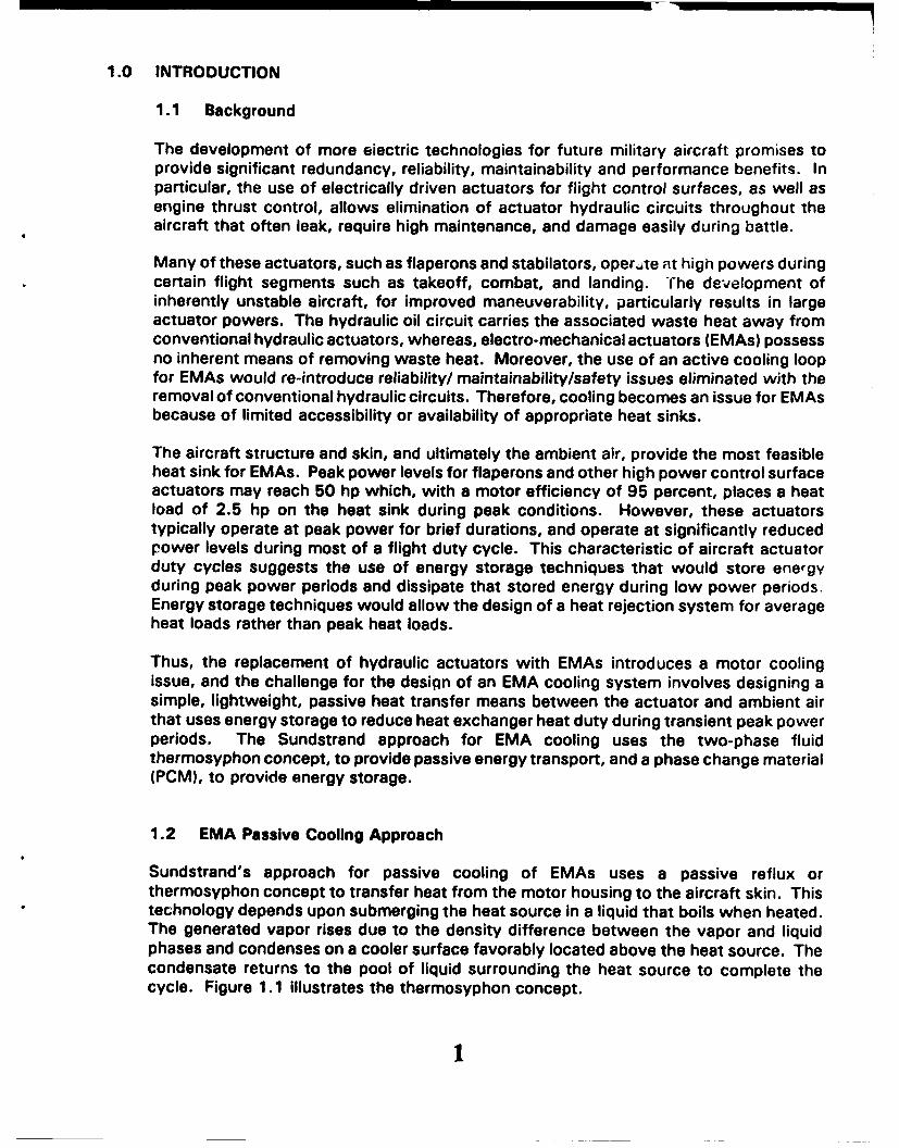
The development of more eiectric technologies for future military aircraft promises toprovide significant redundancy, reliability, maintainability and performance benefits. Inparticular, the use of electrically driven actuators for flight control surfaces, as well asengine thrust control, allows elimination of actuator hydraulic circuits throughout theaircraft that often leak, require high maintenance, and damage easily during battle.
Many of these actuators, such as flaperons and stabilators, oper'.te at high powers duringcertain flight segments such as takeoff, combat, and landing. The development ofinherently unstable aircraft, for improved maneuverability, particularly results in largeactuator powers. The hydraulic oil circuit carries the associated waste heat away fromconventional hydraulic actuators, whereas, electro-mechanical actuators (EMAs) possessno inherent means of removing waste heat. Moreover, the use of an active cooling loopfor EMAs would re-introduce reliability/ maintainability/safety issues eliminated with theremoval of conventional hydraulic circuits. Therefore, cooling becomes an issue for EMAsbecause of limited accessibility or availability of appropriate heat sinks.
The aircraft structure and skin, and ultimately the ambient air, provide the most feasibleheat sink for EMAs. Peak power levels for flaperons and other high power control surfaceactuators may reach 50 hp which, with a motor efficiency of 95 percent, places a heatload of 2.5 hp on the heat sink during peak conditions. However, these actuatorstypically operate at peak power for brief durations, and operate at significantly reducedpower levels during most of a flight duty cycle. This characteristic of aircraft actuatorduty cycles suggests the use of energy storage techniques that would store energyduring peak power periods and dissipate that stored energy during low power periods.Energy storage techniques would allow the design of a heat rejection system for averageheat loads rather than peak heat loads.
Thus, the replacement of hydraulic actuators with EMAs introduces a motor coolingissue, and the challenge for the design of an EMA cooling system involves designing asimple, lightweight, passive heat transfer means between the actuator and ambient airthat uses energy storage to reduce heat exchanger heat duty during transient peak powerperiods. The Sundstrand approach for EMA cooling uses the two-phase fluidthermosyphon concept, to provide passive energy transport, and a phase change material(PCM), to provide energy storage.
1.2 EMA Passive Cooling Approach
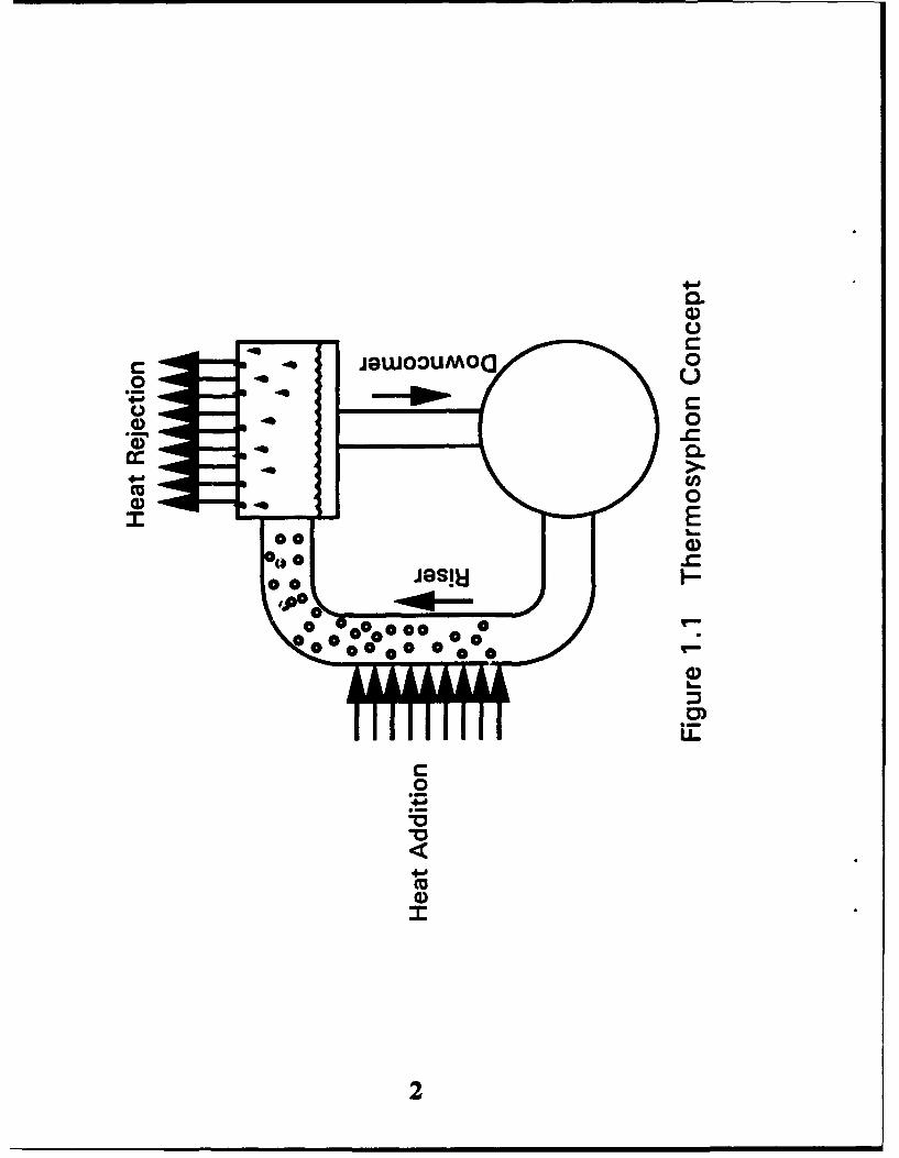
Sundstrand's approach for passive cooling of EMAs uses a passive reflux orthermosyphon concept to transfer heat from the motor housing to the aircraft skin. Thistechnology depends upon submerging the heat source in a liquid that boils when heated.The generated vapor rises due to the density difference between the vapor and liquidphases and condenses on a cooler surface favorably located above the heat source. Thecondensate returns to the pool of liquid surrounding the heat source to complete thecycle. Figure 1.1 illustrates the thermosyphon concept.
1
0.
CL
00
00
0o 0
a)
0-c4-1-
4-d-
Ma

A two-phase fluid provides significantly enhanced heat transfer comoared *G cof.ductionor single phase convection, and heat transport can occur across large distarcas by virtueof vapor flow from the hot source to the cold sink. The reflux heat exchancjer operatesunder the same principle as large scale thermosyphon boilers used in Pankine cycle powerplants, relv;:.g upon the density difference between the liquid phase and vapor phase, andgraiity I" provide the motive force for the natural circulation of fluid. Heat pipes,somr",nat similar devices, rely upon surface tension and a wicking structure rather thangravity to provide the motive force for liquid circulation. In general, th'3 allowable heatflux at the heat source for a reflux heat exchanger exceeds the allowab;--. he-'t Ilux for aheat pipe using the same working fluid.
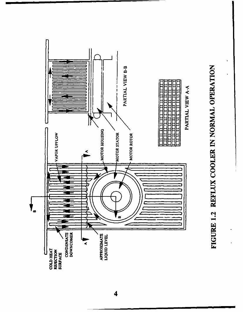
Figure 1.2 illustrates the implementation of this concept for motor CC;6iilw The designcompletely wets the motor housing with the liquid phase of the two- !,ase fluid selectedfor the application, and waste heat from the motor boils the liquid, generating vapor.This vapor flows upward due to density difference through centrally located vaporchannels called "risers" and then condenses on the colder surface associated with theaircraft skin. Liquid condensate then flows downwards though "downcorners" to reenterthe liquid pool surrounding the motor housing.
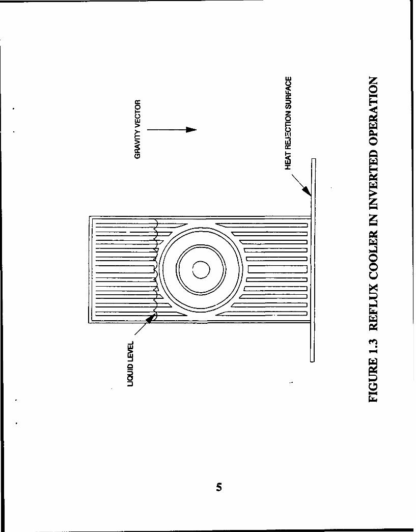
This cooling approach must also provide heat rejection in attitudes other man with thegravity vector in the downward direction. This requires careful consideration forproviding a pool of liquid surrounding the heat source for any attitude, especially invertedflight. Figure 1.3 shows the location of the liquid level during inverted operation, keepingthe motor submerged. Provided the heat exchanger uses only one heat rejection surface,heat transfer will occur at a lower rate since single phase convection replaces the two-phase condensation process at the submerged heat sink during inverted operation.Condensation in the vapor space continues, but energy reaches the ultimate heatrejection area by conduction through the heat exchanger metal and the subcooled liquidphase. Therefore, generated vapor tends to raise the system saturation temperature andpressure since this condition increases the heat transfer resistance between the heatsource and heat sink. The rate of temperature rise depends upon the total thermalcapacitance. The use of upper and lower heat rejertion surfaces would al!owcondensation heat rejection under either orientation.
Heat load changes with this passive cooling approach result in changes in operatingtemperature and pressure for a given sink temperature. In its simplest form, the peaklood defines the design condition for the cooling system, and the series thermalconductances between the motor and ambient air determines the motor temperatures.
Enhancement of the system thermal capacitance through energy storage allows the heatrejection surfaces to be designed for the average load, reducing motor temperatures tothose associated with the average heat load. Energy storage occurs through the use ofeither sensible storage, i.e., addition of mass and specific heat, or the use of a FCM thatstores energy in latent heat. This latter approach typically results in minimum mass andvolume impacts on the system. The Sundstrand EMA cooling concept uses the PCMapproach to minimize weight.
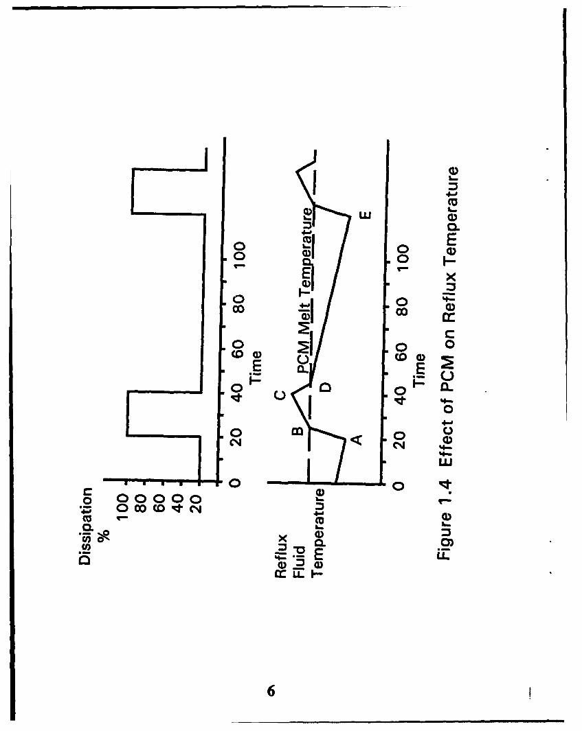
Figure 1.4 depicts the concept of using a PCM for energy storage. The figure illustratesthe two-phase working fluid through the duty cycle represented by the square wave inthe upper half of the figure. Starting at point A, the actuator goes to peak load after a
3
uJ
____ I
___ 0
4I�
00 U, 0 0�2 0 0
U,
0__________ 0
$7 _
6
I.�iI
4
w WOWNo M
I-I
___ w in __.w
50 zI
00> 0
zzii0 E,
00
00 00
to 0 0(o0c 00
E o-0
0 a00
0
0 02 0 00 co COq, CN
6U

period of low load operation. The phase change material, stored within a containmentstructure is completely solid. As the dissipation rises to full load, the fluid temperature(and saturation pressure) rises at a rate dependent on structure specific heat and heattransfer rates. At point B, the fluid temperature reaches the melting temperature of thePCM and it starts to melt, storing energy in the form of latent heat. As the solid materialmelts, the coolant temperature continues to rise, but at a much lower rate, as the heatconducts through the molten material to access the remaining solid material in itscontainer.
At point C, the motor heat load drops from its peak value to a value of 20 percent of thepeak and much lower than the design average heat rejection val, ie of 36 percent of peak.The PCM now acts as a heat source, additive to the motor load, and the temperaturestarts to fall as the molten PCM cools off to its freezintj point D. At this temperature,freezing occurs at the surface of the containei and a treeze front starts to move inwardwithin the PCM. The temperature continues to drop during this process until the actuatoragain experiences peak load at point E.
7

2.0 SPECIFICATIONS
One of the difficulties encountered in designing a heat rejection system for EMAs involvesdefining the design specifications. Limited relevant design data exists from the previous use ofhydraulic actuators and the advent of inherently unstable aircraft designs. Because hydraulicactuators relied upon the hydraulic circuit to carry away waste heat, the design of theseactuators did not require detailed heat rejection requirements, and therefore limited actuator heatrejection experimental data. On the other hand the minimum weight design of a heat rejectionsystem for EMAs requires detailed heat rejection data in order to make effective use of limitedavailable heat sinks. Designing for the use of a PCM particularly requires actuator duty cycledata. In addition to the limited available data, actuator design data for previous aircraft designsmay not apply to next generation aircraft which depend upon inherently unstable aircraft designsfor improved maneuverability. These aircraft use aircraft control surfaces more actively tomaintain control of the aircraft, even during level flight.
Given the shortage of design data, Sundstrand formulated design specifications based uponactuator design experience and limited experimental data for the F-1 5 aileron actuator. Thefollowing requirements served as the design specifications for the EMA heat rejection systemfor Phase I of the program:
"* Design Power 34 hp"* Maximum Ambient Temperature 115 OF"* Minimum Ambient Temperature -65 OF"* Limit motor designs to those using conventional windings insulation systems (windings
temperatures limited to approximately 250 OF)."* Typical mission duty cycle defined based upon design requirements data received by
Sundstrand for F-15 actuators and F-15 aileron actuator flight data (see Figure 2.1).
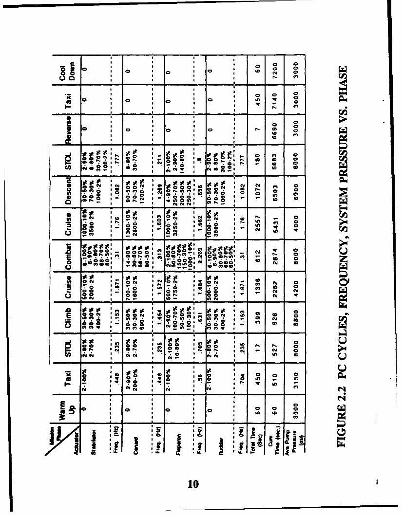
Of these specifications the mission duty cycle particularly affects the design of the heatrejection system. Figure 2.1 breaks a mission into different phases and provides phase duration,actuator power, range of altitude and range of aircraft velocity for each of the phases.Sundstrand defined the mission duty cycle using the actuator design data provided for the F- 15and illustrated in Figure 2.2. Figure 2.2 provides data as a function of the type of actuator;whereas, Figure 2.1 defines a duty cycle for a generic actuator. Sundstrand used the worstcase conditions from Figure 2.2 to arrive at composite conditions presented in Figure 2.1.
Design of a heat rejection system using a PCM relies upon the low power phases (cruise phases)of a mission in order to reduce the overall mission average power. In order to confirm thevalidity of 5 percent power during the cruise phase, Sundstrand evaluated experimental dataprovided by the Air Force for an F-15 aileron actuator. Figure 2.3 presents average power levelsfor each of the evaluated data files, and shows power levels well below 1 percent for all of thecases. Therefore, Sundstrand used a cruise power level of 5 percent for all Phase I designactivities.
Because Figure 2.1 defines ranges of altitude and aircraft speed, Sundstrand used the worstcase heat rejection conditions over the ranges to arrive at a representative duty cycle used formission analysis presented in Figure 2.4. Worst case heat rejection conditions and obtained formaximum altitudes and minimum aircraft speed due to degraded ambient convection heattransfer coefficients.
8

0 0A 0 0 0 C0ciJ N @ 0 0 00 0 w C
C i6C 0
o 00 0 000NuiN 0 0 0 RN C
0 . -0
,LL. to0 0 0 0
-a0 0; 0;
id0 0
LU 0 to 0 0 M
4'. _ _ _ _ _ _ _ _ _
UAILWo
Z--
J 4 4ILui9
I I I I I ! •
O 0 0
= I S I O 0
00 , 0 cc0 N c,
a a S I a m a
I lI I I -i i. (*
* I I
0 I * 0" 0-
0 0: 06
0 I I I I.-
oI I IR -
InP 0 a a 0,'n c a01ýP
III I I
0 to C Y)
in 0 0 to
I ( m C
1 0
•,€•o ,o ":/' o ' , ..60°'60- , -. , . ol 0 "
ID ,,I * •0 ', O',
c , . ,- 0 ic 0oW , " o ° ,•OW 0 ( Y , + Ino
a a oco o,"
I 0 g 0
() I 0 Ie-
04 :-. , V,0 4 m - o
~~i NN 'N N Y• :- o,,, .o . .a0 I c, f " 0 N 0: In 40
~~~.~~ @0 0 50 0 q .0 TQ 1?*MI m 0 --
i n iO at I
0€ ,.*o. ''€6.0. S • =
1' @0 l 0 I n
,,(,,,, ., , - -,.--,
II Ic
a at
* 00 00 in 10 W
I y OY cm c 0Ii•I )I - " , :o ' " , r " a
II I I0 I .
L.~
10
I-0
- i _ _ _ _ _ _ _ _ __s i c
z-4t
cc
v4w
z 0
IL>UA.
(a c I! Ijc uz~ z
0 00 a0 u.16
. >- 0 0 o. r44 > M 1,N 1 >- S-W
24 4 -I w 0 Jwa U
0W 0 ad 0 oW .3 0404~ aC. m O

z
06 0o 0
L9* ) 0 0)
0 0
I- -
4212
3.0 DEMONSTRATION REFLUX COOLER DESIGN SUMMARY
As a result of the trade studies completed during Phase I (see Chapter 5 discussion) Sundstrandmakes the following recommendations for the demonstration reflux cooler design:
0 Demonstration Motor- Modified National Launch System (NLS) inductionmotor. Modifications include removal of the resolver,replacement of the housing with a reflux cooler, andsimplifications of the end plate and shaft.
0 Working Fluid - 3M Company's fluorinated or%3nic compound, FC-75.
0 PCM- Acetamide.
* Heat Exchanger - Brazed, plate fin construction with alternating workingfluid and PCM layers.
13
4.0 ANALYTICAL METHODS
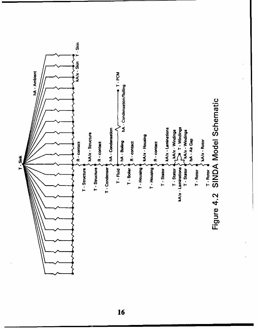
4.1 SINDA Model Description
Sundstrand developed a nodal thermal model of an EMA incorporating a reflux cooler, using SINDA(Systems Improved Numerical Differencing Analyzer). The model includes all significantcornductances between the motor (heat source) and ambient air (heat sink). Figure 5.1 illustratesthe use of a reflux cooler for motor cooling and the heat transfer conductances separating thernoi:or and ambient air. Conductances include boiling, condensation, convection across the motorair gap, conduction through the reflux cooler, interface contact conductances, conduction throughthe aircraft structure, heat spreading across the aircraft wing and convection to the ambient air.Figure 5.2 schematically illustrates the node and conductor network that models the heat rejectionsysvem.
The model calculates heat transfer areas within the cooler assuming a brazed plate fin heatexchanger construction, and requires the user to specify fin geometry and the generalized coolergeometry parameters illustrated in Figure 5.1. The model calculates all geometric parameters ona per unit length basis axially along the shaft, and requires user input data on a per unit lengthbasis. In effect, the model assumes an infinitely long motor. This approach results in a moregeneralized modelling approach.
Usirng the input data and internally calculated data, the model estimates heat transfer coefficientson the working fluid side of the heat exchanger and calculates required conducta~tce andcapacitance values. This model does not perform a detailed thermal-hydraulic analysis of the ref luxprocess, but estimates the boiling heat transfer coefficient using a pool boiling correlation andcondensing heat transfer coefficient using a derivation for film condensation on a vertical flat plate.In result, the model estimates motor and cooler temperatures as a function of operating conditions,and performs both steady state and transient analysis. Sundstrand used the model toparametrically identify controlling heat transfer conductances, characterize the effects of coolergeometry, study the effects of using PCM, and select the working fluid and PCM.
4.2 Model Inputs/Defaults
Figure 5.3 presents the SINDA model input parameters and default values where applicable.Several of the parameters depend upon the analysis condition or the PCM selection, and do nothave default values. As previously mentioned, the units on several of the parameters illustrate themodelling of the motor and cooler on a per unit length basis. In addition to the parametersillustrated in Figure 5.3, the model also uses working fluid property arrays, that depend upon thefluid selection, in order to estimate heat transfer coefficients on the fluid side of the heatexchanger.
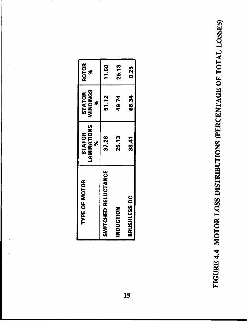
Several of the motor Input parameters presented In Figure 5.3 reflect the National Launch System(NLS) induction motor design that Sundstrand originally proposed as the demonstration motor forthe program. During the trade studies Sundstrand evaluated the effects of motor types includinginduction motors, switched reluctance motors and brushless DC motors. For these motor tradesthe study relied upon the NLS induction motor finite difference model, but varied the lossdistributions within the rotor and stator as a function of the type of motor. Varying the motorfinite difference motor model would have required detailed design activities for each of the threetypes, which was beyond the scope of the program. Figure 5.4 presents the distribution of lossesused for the trade studies. These distributions result from Sundstrand's motor design experience.
14
'D 7
CC
C-CL
0
UU
15)
S -U)
2:
2D
0
c-.2 o aC I
Cp .S
SO! a C6 C,c coc r.C
Cq~j
16

Ambient Boundary Conditions
Sink temperature (parameter)Ambient heat transfer coefficient (variable)Motor air gap heat transfer coefficient (variable)
Geometry Data
Motor Geometry:
Housing OD 4.25 in.Stator OD 3.75 in.Rotor OD 2.25 in.
Cooler Generalized Geometry Ratios:
Structure width to motor OD (Ws/Dh) 3.0Condenser width to motor OD (Wc/Dh) 3.0Evaporator width to motor OD (We/Dh) 2.0Cooler height to motor OD (Hc/Dh) 1.0
Aircraft Skit,:
Aircraft skin thickness0.050 in.
Plate Fin Geometry:
Fin thicknessFin count 0.010 in.Fin length 10.0 fins/in.Fraction of cooler occupied by working fluid (remainder occupied 0.25 in.by PCM) 0.50
Conductance/Capacitance Data
Aircraft Structure:
Thickness 0.75 in.Density (aluminum) 0.098 Ibm/in 3
Specific heat 0.23 Btu/ibm-°FThermal conductivity 100.0 Btu/hr-ft-*F
Motor Housing:
Capacitance 0.0732 Btu/O F/in.Conductance 418.3 Btu/hr-OF/in.
FIGURE 4.3 SINDA MODEL INPUTS/DEFAULTS
17
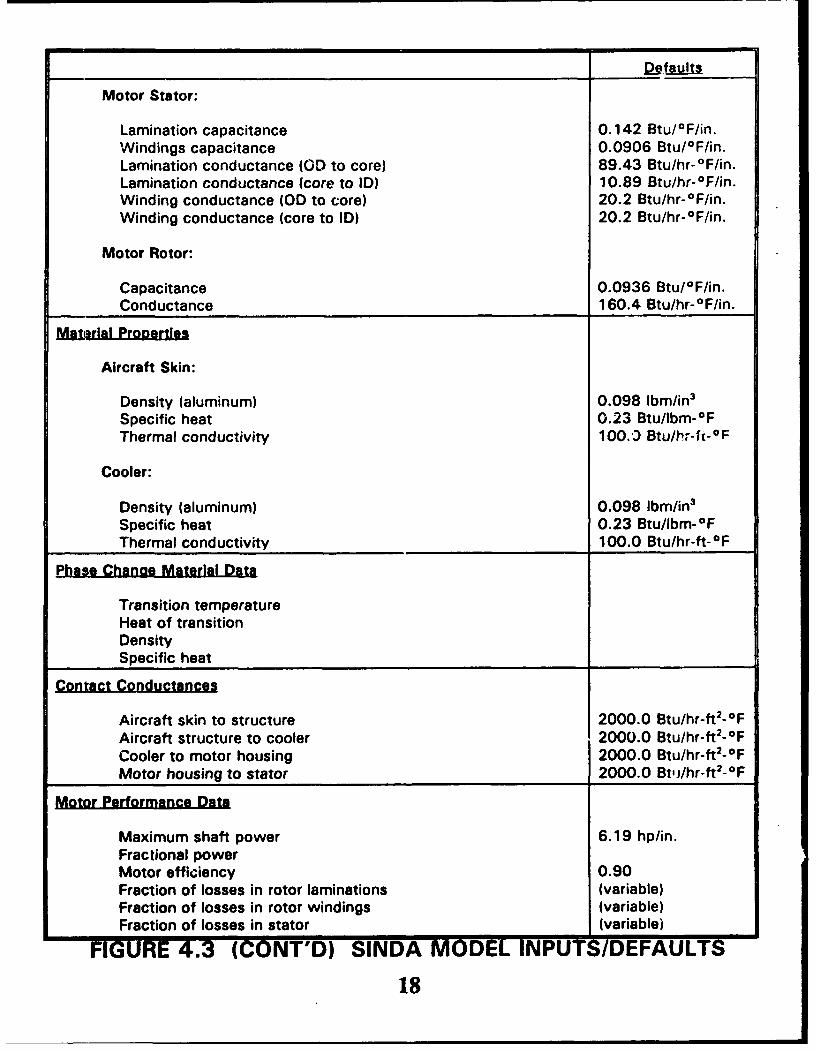
Motor Stator:
Lamination capacitance 0.142 Btu/0 F/in.Windings capacitance 0.0906 Btu/OF/in.Lamination conductance (GD to core) 89.43 Btu/hr-0 F/in.Lamination conductance (core to ID) 10.89 Btu/hr-OF/in.Winding conductance (OD to core) 20.2 Btu/hr-OF/in.Winding conductance (core to ID) 20.2 Btu/hr-*F/in.
Motor Rotor:
Capacitance 0.0936 Btu/1F/in.Conductance 160.4 Btu/hr-OF/in.
Material Prooertles
Aircraft Skin:
Density (aluminum) 0.098 Ibm/in 3
Specific heat 0.23 Btu/Ibm-OFThermal conductivity 100.)0 Btu/hT-- 1- 0 F
Cooler:
Density (aluminum) 0.098 Ibm/in 3
Specific heat 0.23 Btu/Ibm-OFThermal conductivity 100.0 Btu/hr-ft-OF
Phase Change Material Data
Transition temperatureHeat of transitionDensitySpecific heat
Contact Conductances
Aircraft skin to structure 2000.0 Btu/hr-ft2-OFAircraft structure to cooler 2000.0 Btu/hr-ft2-OFCooler to motor housing 2000.0 Btu/hr-ft 2-OFMotor housing to stator 2000.0 BtJ/hr-ft 2 -OF
Motor Performance Data
Maximum shaft power 6.19 hp/in.Fractional powerMotor efficiency 0.90Fraction of losses in rotor laminations (variable)Fraction of losses in rotor windings (variable)Fraction of losses in stator (variable)
FIGURE 4.3 (CONT'D) SINDA MODEL INPUTS/DEFAULTS
18
C-4,
o n 0;0 N
CC 00 Z
4' (iE) Z- L
Op CO CV) ISN V- 4.
rz ui ('5
0
U C,
0 0 Z 0LU 0 (
u) 0400
19

4.3 Correlations
Analysis of the EMA cooling approach required the use of a number of correlations eithercalculated directly within the model or used to estimate model input data. The EMA cooleranalysis required correlations for the following parameters:
"* Ambient heat transfer coefficient."* Viscous boundary layer heating."* Air gap heat transfer coefficient."* Boiling heat transfer coefficient."* Condensation heat transfer coefficient."* Fin efficiency.
The paragraphs wh;ch follow present the correlations selected for calculations.
Ambient Heat Transfer Coefficient
Correlation for turbulent flow over a flat plate (reference [171):
NUL = Pr"' (0.037Re°0 8 - 850)
where:Nu, = Nusselt number.Pr = Prandtl number.Re = Free stream Reynolds number.L = Characteristic length.
= 3.0 ft.
Viscous Boundary Layer Heating
Correlation for viscous heating within the boundary layer (reference [18]):
TO = T. + CU. 2 /2CP
where:TL = Fluid temperature within the boundary layer (used as the sink temperature).T. = Freestream temperature.U. = Freestream velocity.CP = Fluid specific heat.C = PrTl - laminar boundary layer.
= Pr1'3 - turbulent boundary layer.
20
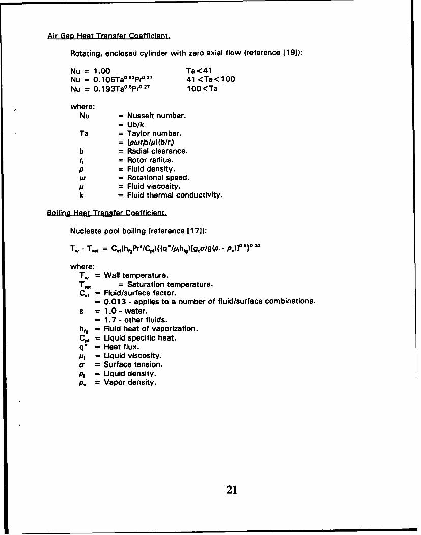
Air Gal Heat Transfer Coefficient.
Rotating, enclosed cylinder with zero axial flow (reference [19]):
Nu = 1.00 Ta<41Nu = 0.106Ta 0
.3Pro"27 41 <Ta< 100
Nu = 0.193Ta°'5Pr°'27 100<Ta
where:Nu = Nusselt number.
= Ub/kTa = Taylor number.
= (pwrib/p)(b/r,)b = Radial clearance.r, = Rotor radius.p = Fluid density.w = Rotational speed.p = Fluid viscosity.k = Fluid thermal conductivity.
Boilina Heat Transfer Coefficient.
Nucleate pool boiling (reference [117]):
Tw - T., = C.f(hfgPrf/Cpi)((qu/pihfg)[g 0 /g(pI- p-)]0.5)0.3
where:Tw = Wall temperature.T,,= = Saturation temperature.Cof = Fluid/surface factor.
= 0.013 - applies to a number of fluid/surface combinations.s = 1.0 - water.
= 1.7 - other fluids.hfg = Fluid heat of vaporization.C• = Liquid specific heat.q" = Heat flux.#I = Liquid viscosity.a = Surface tension.p, = Liquid density.pv = Vapor density.
21
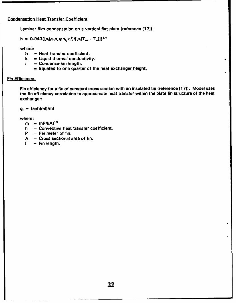
Condensation Heat Transfer Coefficient
Laminar film condensation on a vertical flat plate (reference [171):
h - 0.943{Lpo(p,-p,)ghgk,3J]/[Ip,(T. _ T.)])114
where:h = Heat transfer coefficient.k, = Liquid thermal conductivity.I = Condensation length.
= Equated to one quarter of the heat exchanger height.
Fin efficiency for a fin of constant cross section with an insulated tip (reference [171). Model usesthe fin efficiency correlation to approximate heat transfer within the plate fin structure of the heatexchanger:
of = tanh(ml)/ml
where:m = (hP/kA)112
h = Convective heat transfer coefficient.P = Perimeter of fin.A = Cross sectional area of fin.I = Fin length.
22

5.0 TRADE STUDIES
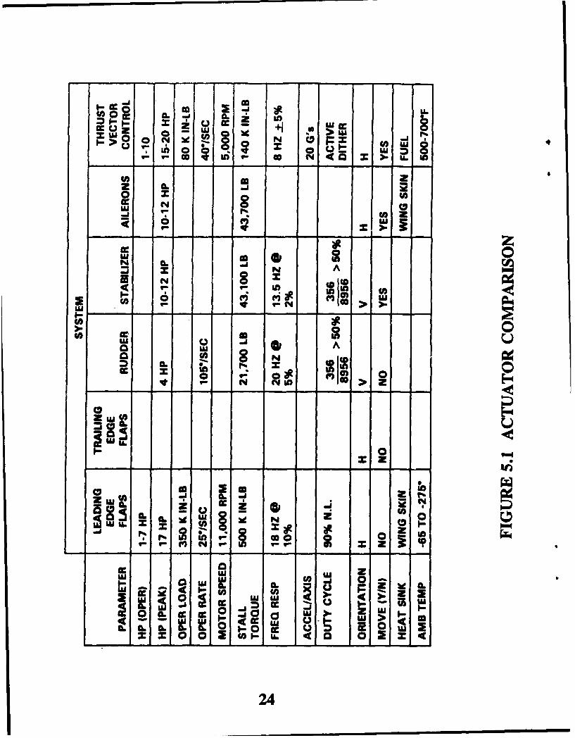
5.1 Actuator Comparison
Figure 5.1 presents a comparison of actuator types and their requirements. This figureillustrates widely varying power levels and duty cycles dependent upon the type of actuator.Some actuators on aircraft experience very active duty cycles, while many operate for verybrief periods with lengthy periods of inactivity. Characterization of actuator duty cyclespresents one of the more difficult challenges to actuator designers, due to limited actuatorflight data, and yet, duty cycle effects selection of the actuator cooling apprcach. Inactiveactuators may not require any external means of cooling, due to significant thermal mass;actuators with very active and consistent duty cycles may require a.1 ixternal means ofcooling; and active actuators with high, intermittent loads may require an external means ofcooling coupled with PCM.
In addition, Figure 5.1 illustrates differences in the availability of heat sinks between typesof actuators. The location of thrust vector control actuators provides easy access to aircraftfuel as a viable heat sink; whereas, the aircraft skin and ambient air serves as the mostfeasible heat sink for the majority of actuators.
Application of reflux cooling coupled with PCM depends upon:
"* actuator power levels."* actuator duty cycles."* heat sink availability.
Given the varying requirements between actuator types and changing aircraft configurations(inherently unstable aircraft), application of the reflux cooling method requires evaluation onan individual actuator basis.
5.2 Steady State Analysis
5.2.1 Geometry/Design Considerations
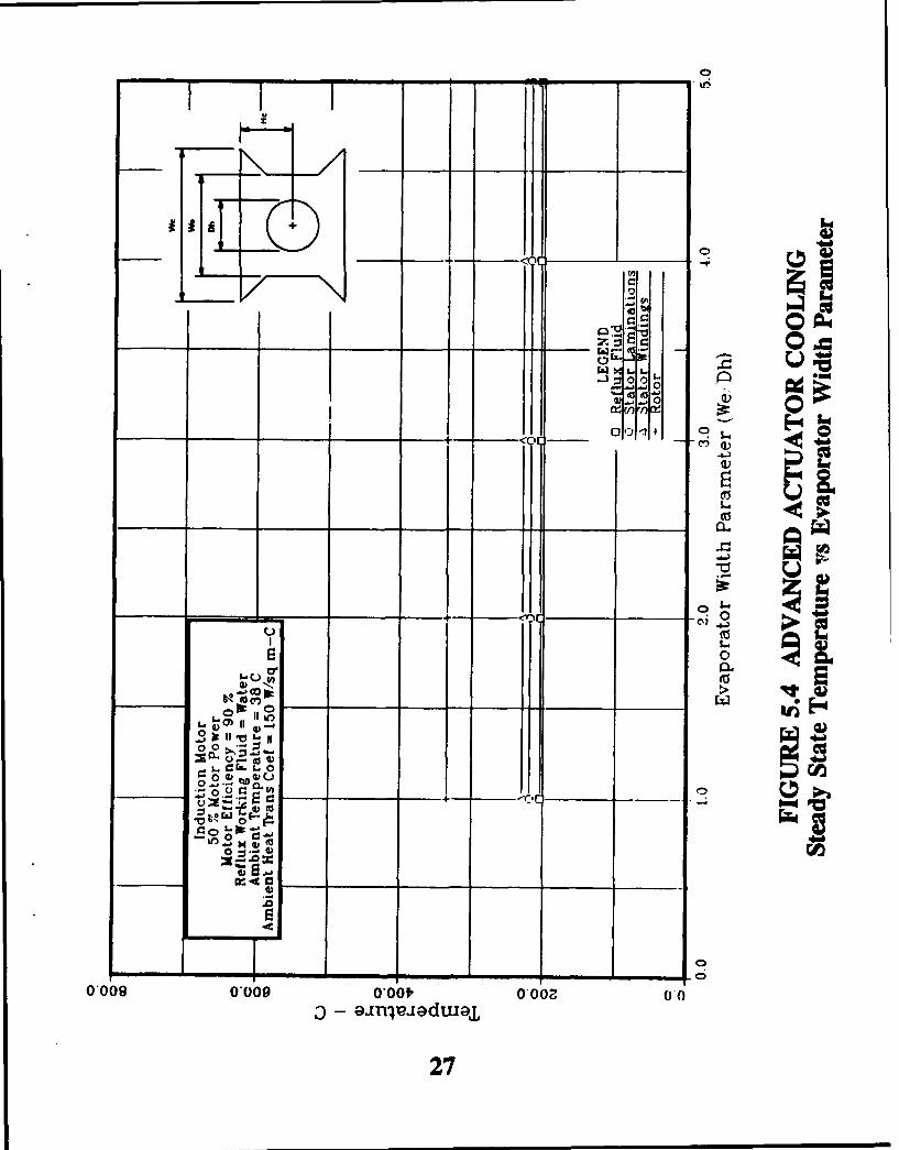
The geometry/design analyses involved parametric studies of some of the parametersthat affect overall cooler performance. These studies helped to identify thoseparameters that most dominate the overall heat transfer process and providedguidelines for defining the cooler geometry. The parameters studied included:
"* Generalized cooler geometry (condenser width, evaporator width, cooler height)"* Fin stock fin count (fins/inch)."* Ambient heat transfer coefficient.0 Structure conductance.
Figures 5.2 through Figure 5.7 present results of the generalized cooler geometry(illustrated in Figure 4.1) parametric studies. These figures present the data in twoforms; as actual temperatures, and as temperature differences for the primaryconductances in the finite difference node/conductor network. The plots illustratingactual temperatures illustrate the effects of the parameters upon overall cooler
23
CC 0 Z .
ccz 0u U.
___ go N4 Z u
10 x Ul
N C
0 @ 0N A
(4 0 2i
w
* In
8 ILOmi ý 0
N 00
00-
cwo 0 J 0~ In
LU0.
w. cczw..A.Zcc cc-M .%a ~
24

0
mE - ( -f-oci
zz
:2 0
0
-4E-4
.4)
tj)
E -0
00
00
to-)-
25

00
IQI
w a 0
.- ' -z 0- U ( 0 - ___
hI 0 0C:0 P
00 *- o0
0___ .0 + x 00,o -
(U1
0i0
000
=- - -ig- 40
os- -4 4L),~~i 8
M2 26
;1 00
ýJý0
-10 41 .
a~tic
____ ____ ____ __ ___ 014 CL~
0'0
-~~~I .JI.~5
S
fomEz
00
- o 251C:4- -- Y0,
0009000 000-0Oa 0V ~ ~ -j . f-:1dv go
P
L. 9.27

+ C") m
00z b.W C 0 V) o
C) tfC)
00.0 0 0 0i
cc,07 ow
-r- C. tw
u , . S) PCCC
.0
s .k
~0 0
000* 009 000,0O0Z 0)
28

-~~W - 00 j m
01 C
coo
0~ Lo
220.~
s. Va -- - 1.[
tO0 M2-
0*009 ~0*00 0o 0.6Z0
era. ~29

a4 0
-4 0
r- .o o )00
00 0 00*
M.E~L.
cu 0
bI)
V MCI
0)0
- 0 - - M
0~
00~
0*009 ~ g. 0,009 L.0f 0,
03

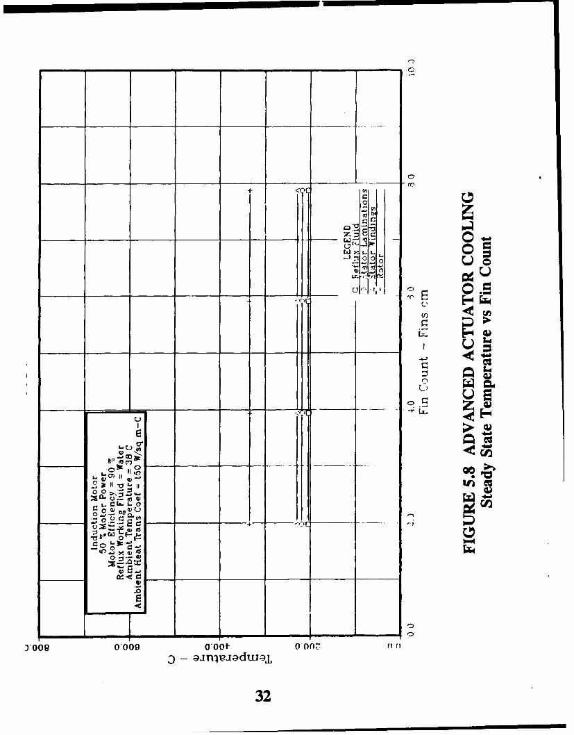
performance, while the temperature difference plots help identify the controllingconductances in the overall heat transfer process. Similarly, Figures 5.8 and 5.9present the effects of fin stock fin counts upon cooler performance and Figures 5.10and 5.11 present the effects of ambient heat transfer coefficient.
Additionally, Figures 5.12 through 5.15 present the effects of structure conductancestudied in two forms. Figures 5.12 and 5.13 present temperatures and temperaturedifferences as a function of conductance value, and Figures 5.14 and 5.15 presenttemperatures and temperature differences as a function of the thickness of analuminum plate separating the cooler and aircraft skin. As a point of reference,reference [241 measured a structural conductance of 21 W/OC/m for a heat pipeattached to a wing strut on an F/A-18 wing section.
Based upon Figures 5.2 through 5.15 one can make the following observations:
"* The controlling heat transfer conductances in the overall heat transfer processinclude ambient convection and convection across the air gap.
"* Structure conductance becomes significant below values of 30 Btu/hr-°F/in."* The condenser width parameter dominates the other geometry parameters as
a controlling conductance due to the dominance of ambient convection.
All of these observations suggest that successful implementation of a reflux coolerrequires the minimization of the heat transfer resistances separating the cooler andaircraft skin, and a maximization of the effective aircraft skin area used for actuatorcooling.
5.2.2 Mission Considerations
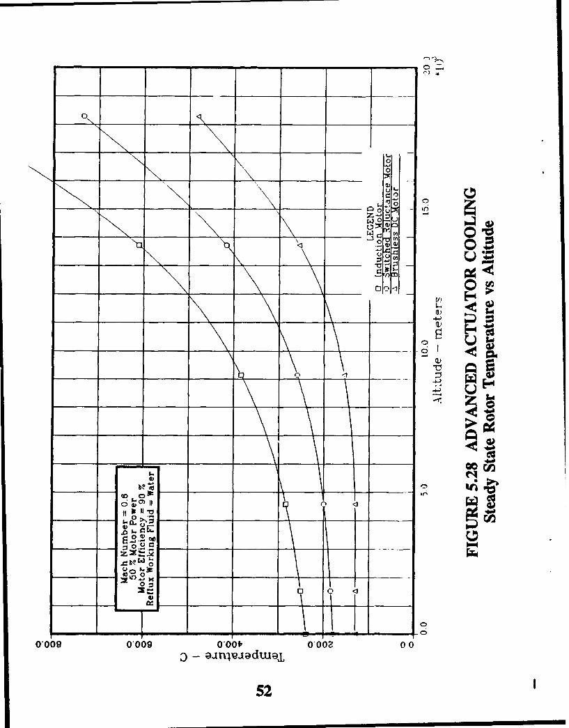
Mission considerations involved the parametric study of aircraft operating conditionsthat affect cooler performance, including altitude and aircraft speed (Mach number).These studies included the effects of altitude and Mach number upon ambienttemper3ture and pressure, aerodynamic heating within the boundary layer, ambientconvection coefficient, and the motor air gap heat transfer coefficient. Figures 5.16through 5.27 present temperatures and temperature differences for the three typesof motors studied at Mach numbers of 0.6 and 1.5 over altitudes ranging from sealevel to 60,000 feet.
Based on Figures 5.16 through 5.27 one can make the following observation:
0 Motor temperatures increase with increasing altitude, despite decreasingambient temperature, due to the dominance of ambient convection.
5.2.3 Type of Motor
Figure 5.28 selectively presents rotor temperature for the three motor types from thedata presented in the previous section. This plot illustrates the differences in rotortemperature for the three motors due to differences in rotor losses. Largertemperature differences resulted in the rotors for the three motors than in the statorssince a passive reflux cooling approach directly cools the stators but indirectly coolsthe rotors.
31
00 bi
V)EE
C,))
L. toa ,P
L.
o0
V I-.50
o..=I.- b0)
Y00 0__009 ____f 0 _00 __
- _ __ __ __32'
0 0
r.- 0
r. 3 0 000
0 0AW, ~0) 0 0'
'000 00
00 0a 0 0 C>0~.
rnr4
_ _ _
_ _ _
00UX-*
'-0 IVu
-? >0.) to- - _0 ,0 -Z_ __D
'-c'
~o- ~ 33

_ _ _ +
-i.
0 C)
-<0
_ _ _ 0 i
.50.
0.
<00-I
0.61 0.00 Tot0,0
340
00
-~ ~ ~ ~ ~ r 0--- _______
0C))
W_ _ r. 0oZ 0 -d
In 00
010<1 x C1011
00))
CDC
0 WO)
to 0_ _ _~ x _ _ -____ ____ 0 i zzo
0,009 0-00 0'0.6
35,4~
+ <0C
n:3- -i ia
U
0 o
C:
00
00 -;
C:. L.
CC
+ <00
- - -C 00
0-009 0,009 000If 0,00Z 0 01
36

00
0 CI0
r.0
000
0a 00 c6 Lo
0000
01 x 0C 0 6
0
6 Q)
000
0
0..! w) Iw0 P
X 0
0,009 0*00f 0 00 0 0
37
0- --- - a
+
0
C,)
0)
ix) V) )
YI)
_ _ _ _ _ 42w
-w
i-in4- :1C 0j%.
0009 ~ ~ L 00 00900 0OZ.- - Pi
":v~g "38
0
0 0_
C) C)
00
o000.
o :% 0
C) u fL)
100
Lr-E-0
00 0,___co:) :3
.0 4
0,009 0*009 0-00f, 0 00 0 Z00
39

n" 000
U)~0
~ 0 C
i I I) •1
C)I
(J.2.
ZI 0u
t o 0
0009 0009 0 0'f, 0.006
) -- aJnWJadtu4
40

U
0
r .5 .(
(0 0
Z v U) 0 ).So _ _-- -p4
CP
00
0.630.009 0*00f* 0 O00fl)I- aou~aJjiajj ajnjpiaduu~j
41

<00
Z:3-0 00
----..- 0
a)a
___ ___ ___<00 -
-4l
0~i
2<0
- - -
009 00 0O~ 0X: 03j -
42

Z" >
0 0 0
00
0_o10 .1_ = 0 C> OP0
V?
IIILI
I JIoh• ., 2
V) 0 ac
00 LU .. ..
0'O0 OO, g 0"001- OOOZ ____
43

"+ _!
IILI
-___-__,_ ____ ___ _..
_____ , __ _ __ __ __ _ ,nIf
00
,o
0009 0009 OOot 00 0 (S- -44
44

-C')
0 0
U CU CU00
Q0
4G) 07 t
wCz 0 0 (n,
S0 0) 4-tm a
0 000 ~-r-) m u=
co_ _ 0_ _ _ o ' _ _
C; I
Olti rf-
00
0090.09 0.001- 0.06Z
45
-.- --<f C
ErJc
.goGo
O4O. O'Og000'/0).O •€
17-
4 -J
CCIO
00
0,0 0,00900f 0*0020
46

to
0 0r Uu
00
00 __ 0
u0 tw Ana
4) 00
0 0- i
-Vu
CPC
.0 Ir~, MV
OLv)
0 > *9
___~ ~( __ _ _ _ _ _ 0-
______~~. Z_ __ __._ r_ __ ____
2~- 0.. t
w~47

00
OC'-,14--
0__z 0 0"- - U
,-•o4
S• 00.....0 0
go
o- 0~~ow
048
48
0 00o
4-1 0h2 0 0
) -,
CU r-o o i 2)PC
00= o .0..
oooe oo• oo•, ooPoo
pum
-)o 00
000 000 -d+ 00
N -- aouaJJial.( ainl,.a~dw~la
49

--•zo
<00
I e X L. 11I I•~~ o o. 1
I ,.•'00 0
01- (:1~t 1 1
iffh7500029 t-a 'r0o 0
05
0:5" 01)oz.=L••
+1 Vo'ooe~~~l oooooI o•o
S- o~n~•JodCo
1 so0,0 0*0 0-6f !0 00
(d to
0 0
00In 0)
Z0 >~ 0 z.
w .0 0 r
:3~ r. 2 40)_ O
0000V U 01.46NC I O 0 : 1 2l
P
0 0 0 (.L. .11M u m u= -En
___ ~ o~l o___ ol F-4 __ _ _ 0 4
00
0 y
0009~~~:X 00-090000000.0 t. 0 3~~Ji Ea.idu
ý 02151
0e
0W
UZ
____~~~~ __ __ _ _ _ A
C!
a4)
0
CEu
.00
0.009 0,009 0-00*' 0*00Z 0 0
52
Figure 5.28 illustrates the following observation:
0 Passive reflux cooling indirectly cools motor rotors requiring careful control ofrotor losses and consideration of rotor temperature limitations.
As discussed in section 5.3, rotor cooling may particularly become a problem forbrushless DC motors and induction motors. Permanent magnet magnetic propertieslimit brushless DC rotor temperatures, while the mechanical strength of copper rotorbars limit induction rotor temperatures.
Additionally, direct cooling of the stator provides significant improvements in motorreliability, since motor reliability depends more upon stator temperatures than rotortemperatures, as long as allowable rotor magnet temperatures are not included for thePM rotor.
5.3 Motor Comparison
Sundstrand evaluated three types of motors for application in EMAs: induction motors,permanent magnet brushless DC motors, and switched reluctance motors. Figure 5.29compares some of the features of the three motor types, and the paragraphs which followprovide a more detailed discussion of the motors.
Based on the discussion which follows and the previously discussed steady state analyses,switched reluctance proved to be the most compatible motor design for the reflux coolingapproach. Moderate rotor losses combined with a more robust rotor design result in lessrestrictive temperature limitations for switched reluctance motors than induction andbrushless DC motors. In addition, the inherent fail degraded performance characteristics ofswitched reluctance motors result in an EMA consistent with the more electric airplanetechnologies approach.
Induction Motor
Limitations:
"* Insulation properties limit the stator operating temperatures. The following describestemperature limitations for insulation systems:
Conventional Insulation: 220 - 250 OC(HML magnet wire with ML or epoxy varnish)
High Temperature Insulation: 400 °C(ceramic insulation)
"* Typically, the mechanical strength of the rotor bars and the design rotor stress levels(rotor speed, rotor diameter, etc.) limit the rotor operating temperatures. Therefore, amotor designer possesses limited control of the rotor temperature limitation throughselection of the rotor bar material, motor design speed, and rotor diameter. As anadditional design consideration, rotor losses typically increase with increasing temperature.
53

Q Q Cm j 0 cc2X.R0 LA L01- ( 0
ZO uj 03 0,.0 wj I. l 0 uX i-b Lo( 00 C5IAu
U. L_ _ IL
uj t .0 w 0 u
Z~ 0 Z
w < . 00 OLl 0w~ Z C
0 CC a
L2Ua N m c c,40 & I-- ~
0 wUu
5 D 2 4n 000 00
U) 0A .0 Z - 4
_ _U__.
54 t
Advantages:
"* Most commonly used motor with many applications within the aerospace industry.
"* Motor designs allow canning of stator with minimal affect upon motor performance.Stator canning allows hermetically sealing the stator from the rotor and air gap, andpermits the use of direct fluid cooling of the stator. In the case of reflux cooling, the useof stator canning would allow the working fluid to directly contact the stator windings andlaminations, thus eliminating some of the series thermal conductances separating thestator and working fluid.
"* Control of induction motors does not require position feedback, therefore simplifyingmotor design.
"* Interference fits between the motor stator and motor housing does not adversely affectinduction motor performance. Interference fits improve the contact conductance betweenthe stator and housing, reducing the temperature drop across the interface.
Disadvantages:
"* Rotor losses for induction motors exceed the rotor losses for brushless DC or switchedreluctance motors. Therefore, rotor temperature limitations often limit motor operatingtemperatures with a cooling method, like reflux cooling, which indirectly provides rotorcooling.
"* A single failure to an induction motor often results in complete motor failure. Splitting thestator and rotor into effectively two motors on the same shaft, provides a degree of faildegraded performance.
Permanent Magnet Brushless DC Motor
Limitations:
"* Insulation properties limit the stator operating temperatures; therefore, the sametemperature limitations as induction motor stators apply to brushless DC motor stators.
"* The magnetic properties of the rotor permanent magnets, as a function of temperature,limit the rotor operating temperatures. Above 150 °C rotor losses rapidly increase due todegraded magnet properties.
Advantages:
* Motor designs allow canning of stator with minimal affect upon motor performance.Stator canning offers similar advantages for reflux cooling as it offers induction motors.
0 Interference fits between the motor stator and motor housing does not adversely affectinduction motor performance. Interference fits improve the contact conductance betweenthe stator and housing, reducing the temperature drop across the interface.
0 Motor efficiencies for brushless DC motors exceed the efficiencies for induction andswitched reluctance motors, reducing heating loads on motor cooling systems.
55
"* Brushless DC motors weigh less than induction and switched reluctance motors of thesame power.
"* Brushless DC motor designs result in minimal rotor losses. However, the temperaturelimitations of the rotor magnets often outweighs the advantages of low rotor losses.
Disadvantages:
"* Rotor permanent magnet temperature limitations severely limit motor operatingtemperatures. This particularly applies to cooling methods like reflux cooling whichindirectly cools the rotor through cooling of the stator outer diameter.
"* A single failure to a brushless DC motor often results in complete motor failure. Splittingthe stator and rotor into effectively two motors on the same shaft, provides a degree offail degraded performance.
"* Control of brushless DC motors requires shaft position feedback and high power
switching.
"• Brushless DC motors cost more than induction and switched reluctance motors.
Switched Reluctance Motor
Limitations:
"* Insulation properties limit the stator operating temperatures; therefore, the sametemperature limitations as induction motor stators apply to switched reluctance motorstators.
"* Typically, thc mechanical strength of the rotor laminations and the design rotor stresslevels (rotor speed, rotor diameter, etc.) limit the rotor operating temperatures. Therefore,a motor designer possesses limited control of the rotor temperature limitation throughselection of the rotor lamination material, motor design speed, and rotor diameter.Though similar rotor constraints apply for both switched reluctance and brushless DCmotors, the mechanical strength of laminations exceeds copper rotor bars, resulting in lessrestrictive temperature limitations upon switched reluctance rotors.
"* Interference fits between the motor stator and motor housing adversely affect switchedreluctance motor performance. A loose fit between the stator and housing reduces thecontact conductance between the stator and housing. Since the reflux cooling conceptprovides cooling across this interface, reflux cooling may require some method of contactconductance enhancement in order to reduce the temperature drop across this interface.
"* Switched reluctance motor performance has proven sensitive to the size of the air gap.This sensitivity to the size of the air gap prevents the use of stator canning, whichprevents a direct cooling approach with the reflux working fluid in direct contact with thestator laminations and windings.
56

Advantages:
"* Switched reluctance motors inherently provide fail degraded performance due to thenumber of individual stator poles. This feature may prove particularly valuable on militaryapplications due to combat environments.
"* The temperature limitations on switched reluctance rotors typically exceed the limitationson induction and brushless DC motors.
"* Switched reluctance motor designs result in lower rotor losses than induction motors.
"* Switched reluctance motors cost less than induction and brusiless DC motors.
Disadvantages:
"* Switched reluctance motors have relatively low efficiency (approximately 85% versus90% and 95% efficiencies for induction and permanent magnet motor, respectively).
"* As mentioned earlier, motor performance is adversely affected by hoop pressure appliedto the stator.
5.4 Transient Analysis
5.4.1 Frequency Response
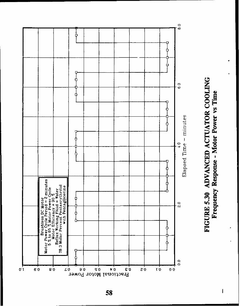
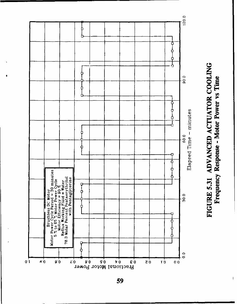
Sundstrand performed a frequency response study in order to characterize theadvantages of using PCM as a function of the frequency of actuator power variations.Sundstrand performed the study by applying square wave actuator power variationsto the reflux cooler model for coolers with and without PCM. For this studySundstrand used a mixture of 78.3 molar percent pentaerythritol with pentaglycerine,solid-solid PCMs.
Figure 5.30 presents the actuator power for a square wave period of two minutes,while Figure 5.31 presents the actuator power for a square wave period of 30minutes. These figures illustrate the variation of actuator power between five percentand 65 percent of maximum power (note change of scale).
Figures 5.32 and 5.33 present transient cooler and motor temperatures as a functionof time for a power cycle period of two minutes for coolers without and with PCM,respectively. Similarly, Figures 5.34 and 5.35 present data for a power cycle periodof 30 minutes.
57
0- to
- m 0 - a -
L -00_ to____
x t-__
oQ
_ _l 60 _ _6 _ _- _ _6 _ _6 _ _ c 9")0
_ _mo _ _ov - a)ljl
U58
00
_ _ _o L _ _
00
00I
.24~
3t0___ _
O-zg__ __ _ __ _ _ _ _ _ 0
1. -0_ __ __~e~
Ir~0 ~~~
II- _ _ _ _ _ _ _-
O'- Wo 9' C9' o f.oCO 2'0 r
Cn ~ 01~ eUT32
~ S __ _ ___ ___ _ __59_

+ <0 c
1400
S<310 I[1:
+ u10 0-
LIT#
+ <0 0
Tl Ell
-U- -1u J
V) CL !. 0 0,
am,-0 0 c <ai it° ,
-II-
00•3009 0"0,0'O0 O1 009 )to- .n . 601/c7St Il II

.71 T
I/I I+__ 1, t
n.
C)u
0~ 11Om 1A, IC-), 40 1
ý20. ~ !,;, Cgo a-0 V;;
C..0 .ME. -W
6"w- I/ n,-e,3),_ ----:3
o A TJMir C)c" :I
0* !O'OOZ 0O091 O'OOT 0 Og 00- - - - - -
61

0--o+ tZ
/ +
+ 0
+ I
0-
10" CO-" 0 O01 0 010 )
3Q, SO Ice~uij
0ý -,!! to(v62

(D+ "
Z )
+~ x3
0+ oi
u WD
+-0, 0
0+
+ý 0
- . - I
(iio
0 m)
fL v
0 C l)
oz 0,00 0,09Tog 0,001 0 ogq 00
63
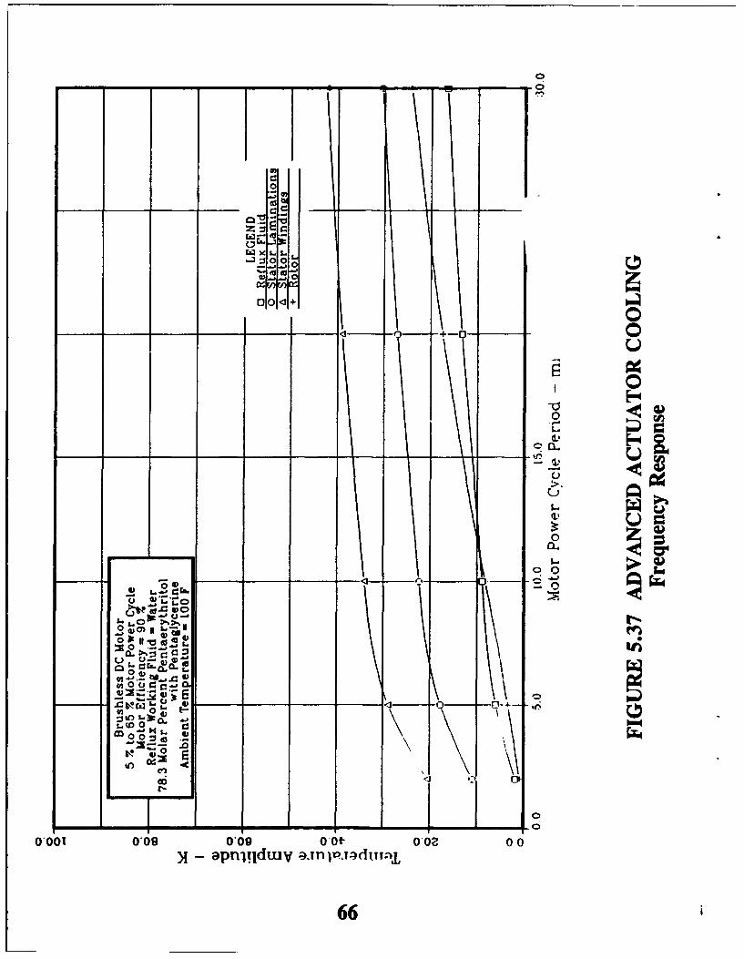
Figures 5.36 and 5.57 compile data for all of the cases studied between periods oftwo minutes and 30 minutes and plot the periodic amplitude of the temperatures asa function of power cycle period for coolers without and with PCM, respectively.
The data in Figures 5.32 through 5.37 illustrates increasing benefits of using PCM asthe power cycle period increases (frequency decreases) and little benefit of PCM forcharacteristically low power cycle periods (higher frequencies). This data suggeststhat PCM provides little benefit for phenomenon characterized by high frequenciessuch as turbulence or active actuator dither, but PCM provides benefit forphenomenon characterized by low frequencies such as high load periods during amission duty cycle (takeoff, combat, and descent). Therefore, the data support thefollowing observation:
* Inherent motor thermal inertia attenuates frequency response for cycle periodsless than five minutes; therefore, PCM provides little benefit for high frequencyactuator duty cycles.
5.4.2 Combat Phase
The combat phase analysis involved estimating cooler performance with and withoutPCM during a combat maneuver. This analysis simply considered the combat phaseof a mission, and served as a preliminary analysis before performing a more detailedmission analysis (presented in section 5.4.3).
Figure 5.38 illustrates the actuator power cycle applied to the model in order tosimulate the transient combat phase of a mission. The analysis used a five percentpower level before entering a fifteen minute combat phase and then a five percentpower level followed as a recovery period. A five percent power level representscruise powers (see section 2.0).
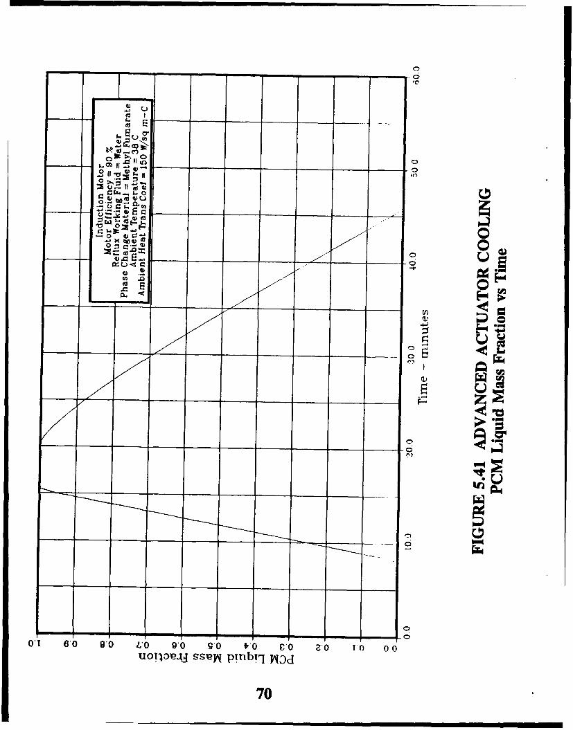
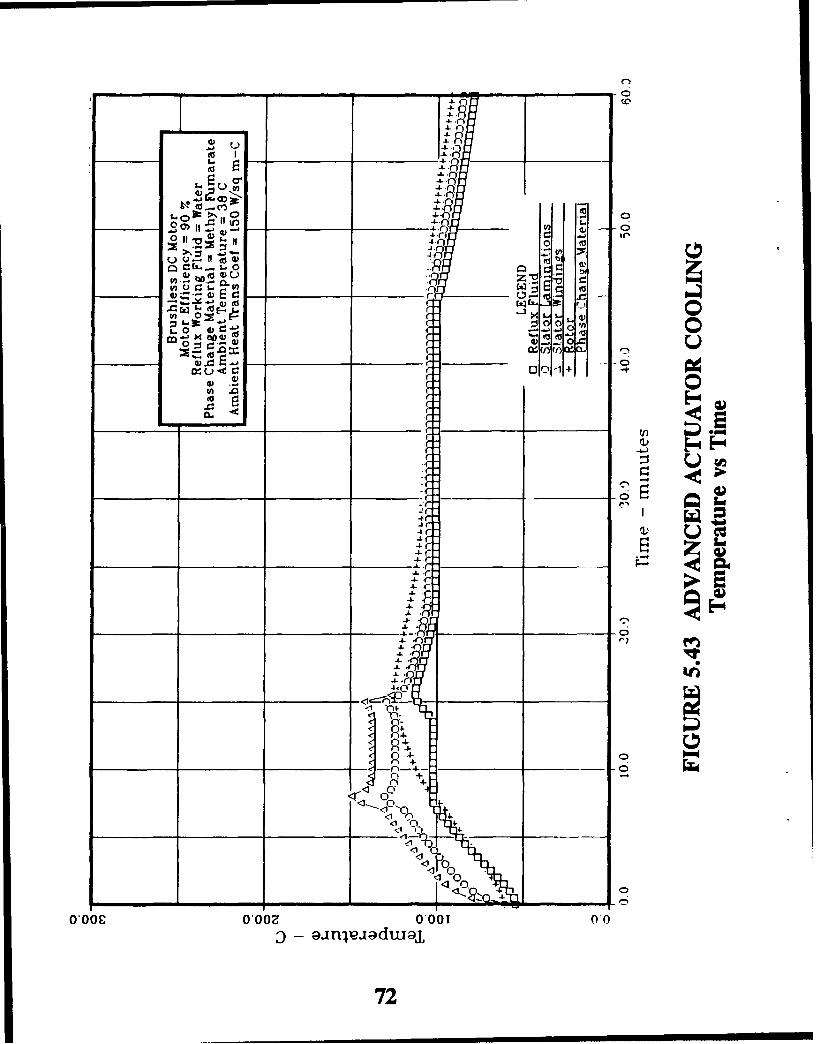
Figures 5.39 and 5.40 present temperatures as a function of time for an inductionmotor for coolers without and with PCM, respectively, and Figure 5.41 presents thePCM liquid mass fraction as a function of time. Figures 5.42 through 5.44 andFigures 5.45 through 5.47 present similar data for a brushless DC motor and aswitched reluctance motor, respectively. The major difference between data for thethree motors lies in the rotor temperatures, as demonstrated in steady state analyses.
These figures further illustrate the advantages of PCM for characteristically lowfrequency actuator power variations such as combat maneuvers.
5.4.3 Typical Combat Mission
The combat mission analyses involved an analysis of the worst case combat missionduty cycle presented in Figure 2.1, and included variations in actuator power, Machnumber, and altitude. The analysis included the effects of altitude and Mach numberon ambient temperature and pressure, aerodynamic heating with the boundary layer,ambient convection coefficient, and motor air gap convection coefficient.
64

00
'AILI
00
o- 4,+
-<1 -__.I
Cd)
0,0010*090,09 O 0,2 0-
M apn~ld~y ainexadu19,
65o
OZ0zz-0,
0 00<M
0 m0
=9 0CU _4 D+ 0
Zzoo
06.
0_001 0_09 0_0_ 0.4 1 0_ _0
X0 -- apZOw ,n l.:dMj
~ s-'66

00
00
V0
U.
BCC
%~0 --- 0d OI~
67)

00 0
;x0.4. ,~ -
-I 91 be-4- z 1
-L C
0- *-4-z
+t +
+4 ~
:. 41 0
+ -- 4-
-0,0 0,00 0,0
68 C

4- (
4-Ctv_ _
4- C
4-4-
-4 .to0((
t CR4-- .C)00
_ _ _ -4-- -
-4-
o-- 01 .
.0 ~~~~4- C- nr dC-4- r*
4- r-+-4.
4- C-4-C r'
.4-
+ 164~+ C
+
++
+4+
0.06C__ 0* 1 zC00
-- 9 'C -69
00
10 O=
0 0
70u

4- n
4ri
(j~)
0 0-
=.o r' f 0
4-C)
4-Cl
+ +A
+' +
0 4-
41 0
<1 ýfl 0
<1<C1" O 000 0+ j
710
4.
4.4~
0 0co
- G) 0
r r.
to - r
0 C - W0-1- -.C
-a-
4r
4r--a. r4-.
4-C
4-.
00
-bo.-i <111
<1 P-C-)'j~+o
0*00CO'OOZ0*00ajl 0dwj
72'

CýC
00
0
.- 5.
CP
01 6'0 90o L'O 90o 9*0 fO £' 0 ' TO1 0 0UOU13ebJ SSey pinbirl WJd
73

0 40
o ý1 C)4-
C) UC3
0-4 (U
4-C
U4 CD
40'
4- 0 .0 0o
.L C)Z 0
.~ o2
+4- +C
4- 0C) 0.-
I C) 0
4-00 0001 00
74- C

4- 44- c -
4-
0 ~-COON:>1 04- C 0
SI 4-I n i--4-- ("
=J.- 4 w u4- in 7
4- 0
(U ~~4- ff:C) "1-- 'L
U.0 -C- r/ r4-f on
"4 -- • -- I, I-
-w- - ,1!
-4-
4- - ''
-4- 4-I.2 0-4- I
4-4- 0"°"
44- 4"
-4-~ ~
4- -
++ ,'+ 3
4- C)
+ < -0,o .++ <
+ +)
0,00C 0t,002 000175 d n
4.75 ,--

00
:J.0
VC
0 4) 00
co'
r i%W5.
01l 6'0 g0 L 0 90 90 v10 IP 0 z0 10 00n
uoTI.PAJ ssej prnbrl lqv1
76
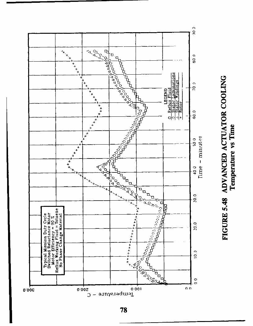
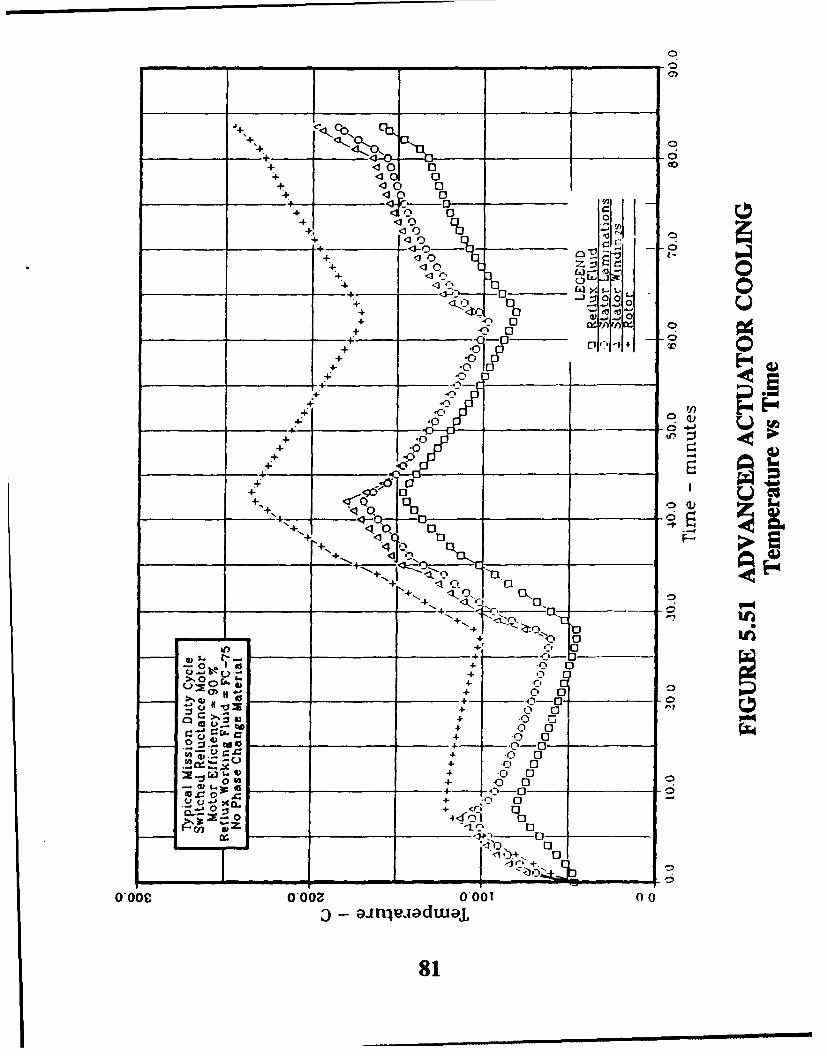
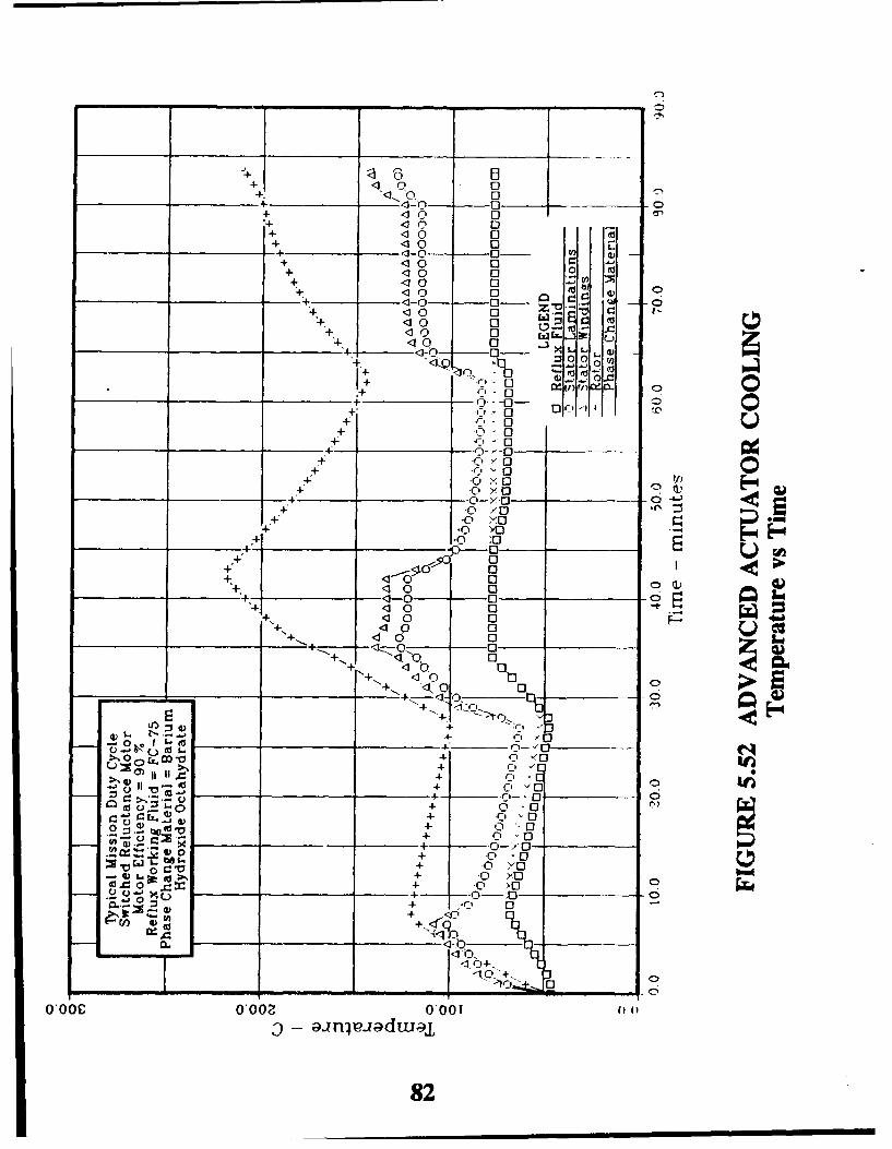
Figures 5.48, 5.49 and 5.50 present temperatures as a function of time using tolueneas a working fluid for coolers using no PCM, barium hydroxide octahydrate as a PCM,and acetamide as a PCM, respectively. Barium hydroxide octahydrate undergoes aphase change at 78 'C (172 °F) and acetamide transitions at 81 'C (178 °F). Figures5.51 through 5.53 present similar data for a reflux cooler using FC-75 as a workingfluid.
The following observations result from these figures:
"* PCM reduces rotor temperatures by approximately 56 °C (100 OF) for typicalhot day mission conditions.
"* Working fluid temperatures for hot day mission conditior-s range from 46 °C to177 °C (115 OF to 350 OF).
"* Suitable PCM transition temperature for hot day mission conditions ranges from77 0C to 107 0C (170 OF to 225 OF).
"* Barium hydroxide octahydrate and acetamide thermally perform similarly sincethey undergo a phase transition at nearly the same temperature.
"* Toluene and FC-75 perform similarly as working fluids since the working fluidboiling and condensation conductances do not dominate the overall cooler heattransfer process.
"* Rotor temperatures lag behind stator temperatures during transients due to thelow thermal conductance across the air gap which reduces the effective timeconstant of the rotor.
"* PCM will increase motor reliability due to the reduction in peak statortemperatures.
The results of the transient mission analysis provide the guidelines for selection of the
reflux working fluid and the PCM (see sections 5.5 and 5.6).
5.5 Working Fluid Comparison
Properties which affect the selection of a working fluid include the following:
"* Freezing temperature."* Critical temperature."* Saturation temperature and pressure."* Heat of vaporization."* Liquid/vapor density difference."* Boiling wall superheat."* Critical heat flux."* Boiling incipience.
Freezing temperature as a selection criteria particularly applies to water as working fluid,since water freezes at a temperature within the temperature limitations of expected actuatorambients and water expands upon freezing. Therefore, water introduces heat exchangermechanical design considerations due to freezing, though often desirable as a heat transferfluid.
77
+ +
+
4 4- 10+ I
1: ;: 0.c
+J+ ____"_
.1- -3:j0
-0-0
+ .n~ o1
+0 -4Q
++C
0- n
++c+
71 -0
+ 10
++
-0--
-,o)
0 0
e, If- C-'0 -
4- 00
- ') L. 0 go +0 00
0 -4-- -'0 0= . :00
.- '0 44 (Q
'104- ~ 4-
0,00C O-Ooz 0,00 I 00
78

+ 51C+- 0 0
+ I+ 10 0+ 10 0
+ 10 0+ <10
- 1-0 0- - t-o 10 0
+ ~' 10 0 0e'1+ 10 0+- <- 0 - r/) r- -
-I-00 0 u 1
10 ), 0 0-,I+-+ <10 0
+ Q
+ ~~0--00++ *.0,0 V
+ -*0-0 U
4j .010 <-;
+_ _ ;V0 0
4-. 10 -0 0 CIS+ <0 0
~00 0JtJ-
00 0 0-0)
I,, 00 9 0- '034- 00
-'t o~ 0 00-Z (:,- -0-
)+ ~ 0 `0
c-0 0
4- :1 00
0j .4AL. '#1- 0
+0 oc0 XL00 0O 0O0 000 0+
-u Umn)d +
W 79

41I 0.10 -0
+ 10 0+ ýl 04+ 10 0+ .10 0+ 10Q 0 r+ 130 00
+ 10 C 0 -.1ýO
4- _10 04- .10 0
_____~ ~ ______ 4-0~ __a~
0-
+0 <0- 0007
-to 00
+ O0>____ _
+ *OxO
0>11~
.4 --+- -~0 0O
0)1
40 -0 P40 .0 .
O>0
00 C IL
0 0~
0 I 0 -i
.4- 0
'-3 to + -400C-0
Q 4) C,-0
W-aba+ 0-0
+ 00
01 0-
C1C.
80
ý00
+ '~.0 0
47 110 0+ I 0
+ 1
+ 1
+ Z0ZtO- ,m
- + - - ~ 0 (.IXL 0+ ~ 00 0
-+4- w0 '0'1+
+ *0
+ .0+ .0
-+4-
+
+ 0
01 1 1
+ + 1 3 r
00
+
+- 00c
2- C-O
+ -~0X.U3+ C-0 0
00 + <r 0)
Z-40 04:
OOO0C O'Ooz 000! 0 0
81
+ 5+4- 10 0
+ 1 0 0
+ '10 0+ 100 0
4+ Q0 0 : o+7 100 0-+ -a1-0 0-Z-
+ '0 0
<1 0 0=1 010 0 Y)
Q- 10 0ý
Q 0 . )f)c L 00
Q.-0 -
00
-+ -. 0-YO J -_____ )
4- 0/0;4: '10 YO
;+10 "0E4---+1 0
o 0
-4 qIo
b .0
____ __ _ _ __ ___ ____ _ 0
14-- C111X. - 0+ 0-10
+ C)~
0 w d 04- 0-04- 0-0
0 wo + -0 y
00
__________-1 0__ _ _ 4-1 0
0*00 T00z 0,001
82

t 1 0o 0
+ _____ __ 0
+ <3 0 0+ < 0 0JI. 4-0 - C
± <30 0 -+ <0 <0 0 _9
-+ -0-0---0- Z~-4- 'd0 0
+; -a0 0_+_ ,- 10 0 0
-0 0"+ :ýIZ 0=
+- -0- 0.0- 0 C<+ c
+- *o0 0+ *0 0
4 0-0.00
-+ -~~0- -0-0'-
+:~ 0
-4 .-0 4--0 -- '
.0- 04 0
+ 4 0 0 F4a00-0
+ *
-0
011 0 D4-C
3~~C -, 0JW~uj
M.Ow . V83
Critical temperature becomes an issue when operating temperatures exceed critical fluidtemperature, since the density difference between the liquid phase and the vapor phaseprovides the motive force for fluid circulation. Supercritical fluids would not exhibit thedistinct density difference between phases.
The relationship between fluid saturation temperature and pressure effect the mechanicaldesign of the heat exchanger since the heat exchanger must contain the fluid pressure.Large saturation pressures within the operating temperature range would result in a heavierheat exchanger in order to carry the loads of containing the fluid pressure.
Heat of vaporization affects the recirculating fluid flow rate required to carry the heat duty.
The density difference between the liquid and vapor phases provides the motive force forfluid recirculation. Fluids operating above the critical point would have little densitydifference between the phases and poor recirculation rates.
The boiling wall superheat provides a measure of fluid boiling characteristics. The resultsof the steady state parametric trade studies suggest that the boiling and condensation heattransfer processes do not control the overall heat transfer process, therefore lessening theimportance of boiling wall superheat as a selection criteria.
Critical heat flux provides a measure of the limiting value of heat flux that results in nucleateboiling. Heat fluxes that exceed the critical heat flux result in transition or film boiling, andsubsequently higher wall superheats.
Boiling incipience represents the heat flux required to initiate the change from single phaseconvection to two phase boiling. Sundstrand experience with reflux coolers has shown thatboiling incipience critically affects ref lux cooler performance. Heat fluxes which do not resultin boiling result in nonisothermal heat exchangers and very poor heat transfer rates.
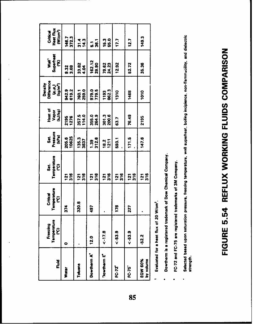
Figure 5.54 presents a comparison of the candidate fluids and the properties of interest, withthe exception of boiling incipience. Of the properties illustrated, the saturation pressureprovides a more critical selection criterion than other properties, since the boiling andcondensation heat transfer conductances did not control the overall heat transfer processof the reflux cooler.
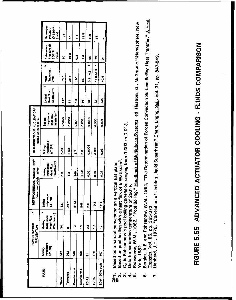
Figure 5.55 compares boiling incipience for the candidate fluids estimated by three methods:
"* Homogenous nucleation [221."* Heterogeneous nucleation based on nucleation site size [20)."* Heterogeneous nucleation neglecting available nucleation site size [211.
Figure 5.55 illustrates large variations between the three methods. Homogeneous nucleationinvolves bulk boiling within the fluid itself; whereas, heterogeneous boiling involves boilingat a surface. Homogeneous boiling requires larger superheats, therefore providing a worstcase analysis of boiling incipience. Sundstrand estimated heterogeneous boiling using twomethods. The one method does not account for the available sites for nucleation, while theother method uses an estimate rof the nucleation site availability as its basis. Neglecting theavailability of nucleation sites may lead to overly optimistic boiling incipience estimates;whereas, some estimate of nucleation site availability leads to more realistic boilingincipience estimates.
84
E 2)
Lo 0
aW NCN 0O N( N N 0
C-4 o 0om .a0 41 aý a? S CI
ca c" m C4 C- U. -
- 50 a
0) .0(D CI wc
4 0 0.f-rI40.. .N N N%
0
N~~4 xnL n0WNM NM Nq N~ NW N N~
C. 0:1 2p 4 im c mr
ca. MM -r.C N 0)1 N V ~* b
- 0 E UC-4 ,4 B-4 , - %U, C 4 -
Cf B, w-,WM M VM -
0) ~ C
r. CO) 1') N4 BIL 2 ~ ~ C . 0-
*u4 V .2
L Wn
S. E
____to LnA
41 C1485
m 5 n Uý 9
U) 0 - 44 *m ) .
- - - -- - - - ~ aco z4
o,(lyA* C4 0 4 D 4
*0 I
m
a) cm
01 x 0an - - -~ . mm.
X o o oo o o C-) E ) cc
o m
0A 0c 4-
a 0 a~ 0 0 ;
- --- ---- -- E 2
In 4 Cia-
- c 0 c40 0(U U -
0 u0 C Iw c200 03 o
CO -- - 0
0 zx C4oi R C; C CO4CC
0~0
02 -
9.00)- E U0 W0
_ _ - - - - - - CD.( z .0 oIC0o
- -- - --

Based on the comparison of candidate fluids and observations noted as a resu.t of steadystate parametric studies, Sundstrand recommends 3M company's fluorinated organiccompound, FC-75, as the demonstration working fluid. Sundstrand based thisrecommendation upon saturation pressure, freezing temperature, wall superheat, boilingincipience, non-flammability, and dielectric strength.
5.6 Phase Change Material Comparison
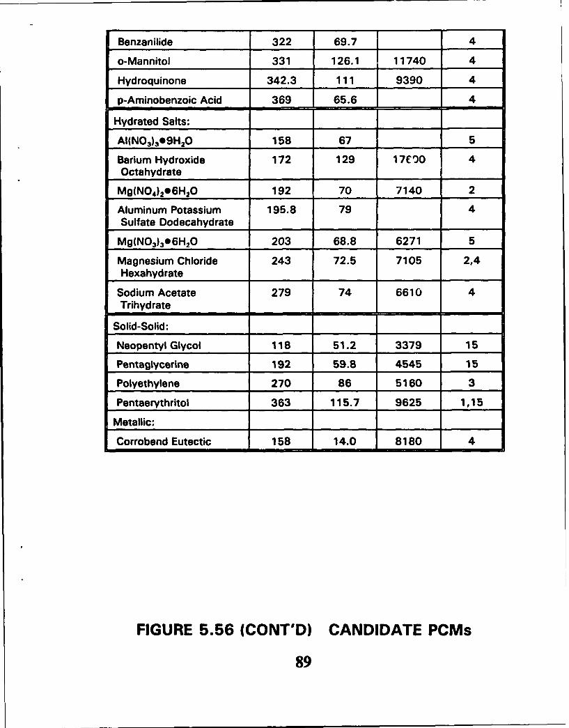
Figure 5.56 presents a comparison of PCMs and their properties for PCMs with transitiontemperatures ranging from 65 to 190 °C (150 to 375 OF). The figure presents transitiontemperature and heat of transition on both a per unit mass and pe unit volume basis.Selection of the transition depends upon the nominal operating tempc,;atures of the refluxsystem. During low power conditions the PCM transition termprature should exceed thereflux fluid saturation temperature; whereas, during transient high power conditions thesteady state saturation temperature should exceed the PCM transition temperature in orderto take advantage of the PCM latent heat. The heat of transition on a per unit mass and aper unit volume basis effects the required PCM mass and volume required to meet knowntransient heat duty requirements.
Figure 5.56 breaks the PCMs into four categories:
"* Nonparaffin organics."* Hydrated salts."* Solid-Solid."* Metallic.
According to reference [41 the following statements apply to the four categories of PCMs:
Nonparaffin Organics:
"* Most numerous of PCMs."* Flammable."* Some are toxic."* Relatively low thermal conductivities."* Attractively high heats of fusion on both a per unit mass and per unit volume basis.
Salt Hydrates:
0 Attractively high heats of fusion on both a per unit mass and per unit volume basis.0 Small volume change upon melting.0 Relatively high thermal conductivities.* Corrosive.
Solid-Solid:
"* Do not require containment structure."* Small volume change upon melting."* Mixtures of pentaerythritol and pentaglycerine allow tailoring of transition temperature.
87

Material Trans. Heat of Heat of Ref.Temp. Trans. Trans.
(mF) (Btu/pbm) (Btu/ft 3 )
Nonpzaraffin Organics:
P-Chloroanaline 156 66.8 5060 4
Stearic Acid 157 85.5 4520 4
Bromcamphor 171 74.7 6760 4
Durene 174.7 67.2 3510 4
Acetamide 178 104 7510 4
Methyl Brombenzoate 178 54.2 4
Dimethytartrate 189 63.0 5110 4
Ethyl Lithium 203 167 4
a Napthol 205 69.9 4780 4
Glutaric Acid e.07.5 37.4 5990 4
P-Xylene Dichloride 212 59.1 4
Methyl Fumarate 216 104 11660 4
Catechol 219.7 88.7 7590 4
Resorcinol 230 4
Quinone 239 73.5 6040 4
Acetanilide 239 65.2 4920 4
Succinic Anhydride 246 87.5 6030 4
Benzoic Acid 251.1 60.9 4813 4
Stilbene 255 71.7 5200 4
Benzamide 261.0 72.7 6080 4
Phenacetin 279 58.7 4
a Glucose 286 74.9 7220 4
Acetal-p-toluidine 295 77.2 4
Phenylhydrazone 311 57.9 4
Salicylic Acid 318 85.5 7700 4
FIGURE 5.56 CANDIDATE PCMs
88
Benzanilide 322 69.7 4
o-Mannitol 331 126.1 11740 4
Hydroquinone 342.3 111 9390 4
p-Aminobenzoic Acid 369 65.6 4
-Hydrated Salts:
AI(NO 3)3e9H20 158 67 5
Barium Hydroxide 172 129 17C00 4Octahydrate
Mg(N0 4)2 06H20 192 70 7140 2
Aluminum Potassium 195.8 79 4Sulfate Dodecahydrate
Mg(N0 3)396H20 203 68.8 6271 5
Magnesium Chloride 243 72.5 7105 2,4Hexahydrate
Sodium Acetate 279 74 6610 4Trihydrate
Solid-Solid:
Neopentyl Glycol 118 51.2 3379 15
Pentaglycerine 192 59.8 4545 15
Polyethylene 270 86 5160 3
Pentaerythritol 363 115.7 9625 1,15
Metallic: I II_ I
Corrobend Eutectic 158 14.0 8180 4
FIGURE 5.56 (CONT'D) CANDIDATE PCMs
89
Metallics:
"* Low heat of transition per unit mass."• High heat of transition per unit volume."* High thermal conductivities.
Based upon the transient mission analysis presented in section 5.4.2, the transitiontemperature of the PCM for the demonstration cooler should fall in the range of 77 to 1070C (170 to 225 OF). Sundstrand narrowed the selection to acetamide and bariumhydroxide octahydrate based upon the transition temperatures and heats of transition.However, consideration of compatibility with aluminum eliminates barium hydroxideoctahydrate due to corrosiveness with aluminum. Therefore, Sundstrand recommendsacetamide as the PCM for the demonstration reflux cooler.
5.7 Demonstration Motor Selection
Based on a trade study of three Sundstrand motor designs, Sundstrand recommendsmodifying a National Launch System (NLS) actuator motor design for the demonstrationmotor. Sundstrand recommended an approach using the NLS motor in the original motor,but performed the trade study to confirm the motor selection. The recommended motoruses an induction design with sealed bearings, and provides 35 hp at 15,000 rpm.Sundstrand selected the design based upon its proven mechanical design, prototypicbearing approach, power supply availability, parts availability, and less complex motordesign. The availability of laminations and rotor bars and the less complex motor designpromise to provide cost advantages.
The three motors studied included:
"* Selected NLS motor design."* Modified NLS motor design using a split rotor/stator."* LV-100 switched reluctance motor.
Figure 5.57 provides a comparison of the three motors. All of the motors requiremodification in order to include the passive ref lux cooled heat exchanger as an integral partof the motor housing.
Though switched reluctance motors are more consistent with the 270 VDC More ElectricAirplane (MEA) technology than induction or brushless DC motors, Sundstrand did notselect the LV-100 motor for a number of reasons. The LV-100 motor uses an oil flow loopto provide bearing lubrication and rotor cooling which would result in compromised testingof the passive cooling approach proposed for EMA cooling. Elimination of active rotorcooling would require major modifications to the bearing lubrication flow loop orreplacement of the oil lubricated bearing with a sealed bearing design. In addition, testingof the switched reluctance motor would require use of an Army power supply (requiringapproval) or the purchase of a power supply at a considerable cost penalty (approximately* 130,000). Since the primary objective of the program involves demonstrating thepassive cooling approach for EMAs, selection of an induction motor rather than a switchedreluctance motor will not invalidate results of the development program.
90

INDUCTION PERMANENT SWITCHMAGNET RELUCTANCE
BRUSHLESS DC
RATING FRACTIONAL TO FRACTIONAL TO FRACTIONAL TO1000'S OF KW 100'S OF KW 1000'S OF KW
SPEED < 200 M/SEC < 250 M/SEC < 300 M/SECPERIPHERAL PERIPHERAL PERIPHERAL
SPEED SPEED SPEED
EFFICIENCY 85 - 92% HIGH: 90 - 95% LOW: APROX85%
LOSSES IRON AND IRON AND COPPER IRON/COPPERCOPPER ROTOR STATOR ONLY STATOR IRON
AND STATOR ROTOR
WEIGHT INTERMEDIATE MINIMUM HIGHEST
TEMPERATURE INSULATION MAGNET LIMITED INSULATIONLIMITED (150 DEGREES C) LIMITED
STALL TORQUE GOOD GOOD VERY GOOD -MINIMALLOSSES
FAULT TOLERANCE NO NO YES
COST INTERMEDIATE HIGH LOW
FIGURE 5.57 ELECTRIC MOTOR COMPARISON
91

Sundstrand also evaluated a variation of the NLS motor design currently in developmentthat uses a split rotor/stator design that provides fail degraded performance. Sundstranddid not select the NLS split motor design since the motor uses a nonprototypic rotor/statordesign, and the motor mechanical design has not been proved by test.
5.8 Manufacturing Approach
Sundstrand selected the brazed plate fin heat exchanger manufacturing approachillustrated in Figure 5.58. The selected manufacturing approach offers the followingadvantages:
"* Proven manufacturing approach.
"* Integral motor housing/cooler.
"* Provides extended surface.
"* Alternating layers of working fluid and PCM reduces conduction lengths.
"* Vertically oriented fins in the working fluid layers provides direction of recirculatingflows.
"* Horizontally oriented fins enhance conductivity within PCM layers and promote lateralheat spreading.
Though Figure 5.58 illustrates horizontally oriented fins within the PCM layersconsideration of the freeze and thaw process may suggest vertically oriented fins.Vertically oriented fins would allow free movement of the liquid within the heat exchangerduring the thaw process.
92
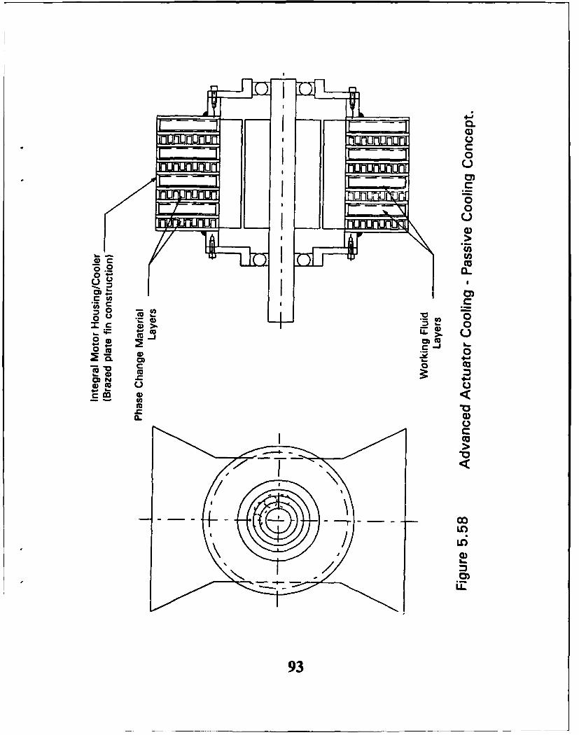
F- 0
I~n inI-uuuuC0
0)
0.r
0
- -- 0
O( 04) 41 -
0 0 m C
cm
CLC
co
LO~
IL
93

6.0 CONCLUSIONS
Based on the tasks completed during Phase I Sundstrand has reached the followingconclusions:
"* EMA cooling offers several challenges due to actuator power levels approaching a levelof 50 hp, limited heat sink availability for passive cooling approaches, and weaklydefined actuator duty cycles, dependent upon type of actuator.
"* Capitalizing upon the advantages of EMAs over conventional hydraulic actuators (i.e.,elimination of hydraulic lines) requires a passive actuator cooling approach like refluxcooling.
"* The controlling heat transfe; conductances for a passive reflux EMA cooler includeambient convection and convection across the motor air gap. These conclusionssuggest the use of a large condenser foot print area to make use of a large aircraft skinarea for convection, and result in difficult cooling of motor rotors.
"* The passive reflux cooling approach provides direct cooling of motor stators butindirectly cools motor rotors; however, motor reliability depends more upon statortemperatures than rotor temperatures.
"* Magnet temperature limitations result in difficult passive cooling of brushless DCmotors despite the fact that rotor losses for the other motors considered exceed thoseof brushless DC motor.
"* High rotor losses result in difficult cooling of induction motors despite the fact that theupper temperature limitation for induction motors exceeds brushless DC motors.
"* Rotor materials and moderate rotor losses suggest switched reluctance motors as themost likely candidate for passive reflux cooled EMAs.
"* PCM reduces motor temperatures for lower frequency power transients such as highpower phases of combat missions with the inherent thermal inertia of the motordominating at lower frequencies.
94

7.0 RECOMMENDATIONS
Based upon the tasks completed during Phase I Sundstrand makes the followingrecommendations:
"* The robust nature of switched reluctance rotors and inherent fail degraded performancejustify switched reluctance motors as the motor selection for future passive refluxcooled EMAs.
"* Low frequency actuator power transients, such as the combat phase of a mission,justify the use of PCMs, while PCMs provide no advantage for high frequencytiansients, such as turbulence.
"* Sundstrand recommends a modified NLS induction motor for the demonstration motorbased upon proven mechanical design, prototypic bearing approach, power supplyavailability, and less complex motor design.
"* Sundstrand recommends acetamide as the demonstration PCM based upon transitiontemperature, heat of transition, and compatibility with aluminum. This selection couldvary depending on mission requirements.
"* Sundstrand recommends FC-75 as the demonstration working fluid based uponsaturation pressure, wall superheat, boiling incipience, nonflammability, and dielectricstrength.
"* Sundstrand recommends a brazed plate fin heat exchanger construction since thisapproach provides a proven manufacturing technique, extended surface, reducedconduction lengths, and enhanced conduction within the PCM layers.
95
8.0 REFERENCES
[1] Glen E. Thorncraft and Fred S. Gunnerson, Performance Evaluation of a Solid StatePhase Change Material for Thermal Storage Applications, Proceedings of the 26thIntersociety Energy Conversion Engineering Conference, Boston, Massachusetts,August 4-9, 1991.
[2] W.M. Rohsenow, J.P. Hartnett and E.N. Ganid, Handbook of Heat TransferAplcgt•ti_, 2nd Edition, McGraw-Hill Book Company, 1985.
[31 Eric C. Guyer, Handbook of Agolied Thermal Design, McGraw-Hill Inc., 1989.
[41 D.V. Hale, M.J. Hoover and M.J. O'Neill, Phase Change Materials Handbook, LockheedMissiles and Space Company, NASA Contractor Report CR-61363, September 1971.
[51 William R. Humphries and Edwin 0. Griggs, A Design Handbook for Phase ChangeThermal Control and Energy Storaoe Devices, NASA Technical Paper 1074, November1977.
[61 "Dowtherm Heat Transfer Fluids," The Dow Chemical Company, 1969.
[71 "Fluorinert Electronic Liquids - Product Manual," 3M Company, 1990.
[81 "Prestone II - Physical Properties Data," Union Carbide Corporation, Eighth Edition,1980.
[91 Sundstrand Toluene Properties Handbook, 1974.
[101 G.J. Ganz, C.B. Allen, J.R. Downey, Jr., and R.P.T. Tomkins, "Physical Properties DataCompilations Relative to Energy Storage, I. Molten Salts: Eutectic Data," ReportNSRDS-NBS 61, Part I, 1978.
[111 G.J. Ganz, C.B. Allen, N.P. Bansal, R.M. Murphy, and R.P.T. Tomkins, "PhysicalProperties Data Compilations Relative to Energy Storage, I. Molten Salts: Data onSingle and Multi-Component Salt Systems," Report NSRDS-NBS61, Part II, 1979.
[121 G.J. Ganz and R.P.T. Tomkins, "Physical Properties Data Compilations Relative toEnergy Storage. IV. Molten Salts: Data on Additional Single and Multi-Component SaltSystems," Report NSRDS-NBS 61, Part IV, 1981.
[131 1989 ASHRAE Handbook - Fundamentals, American Society of Heating, Refrigeratingand Air-Conditioning Engineers, Inc., 1989.
[141 "Therminol 66 Heat Transfer Fluid," Technical Bulletin (T-66), Monsanto Company,1973.
[151 Benson, D.K., Webb, J.D., Burrows, R.W., McFadden, J.D.O., Christensen, C.,"Materials Research for Passive Solar Systems: Solid-State Phase-Change Materials,"Solar Energy Research Institute Report, Task Nos. 1275.00 and 1464.00 WPA304,March 1985 (Available through NTIS, SERI/TR 255-1828 Category 62A).
96
[16] Benson, D.K., Burrows, R.W., and Webb, J.D., "Solid State Phase Transitions inPentaerythritol and Related Polyhedric Alcohols," Solar Energv Materials, Vol. 13,North-Holland, 1986, 133-152.
[17] Holman J.P., Heat Transfer, Fifth Edition, McGraw-Hill Book Company, 1981.
[181 Telecon between Kirk Yerkes, Wright-Patterson Air Force Base, and Kevin Funke,Sundstrand, May 26, 1992.
[191 Heat Transfer and Fluid Flow Data Book, General Electric Company, 1970.
[201 Rohsenow, W.M., "Pool Boiling," Handbook of Multiohase Svstem_•, Editor, Hestroni,G., McGraw-Hill-Hemisphere, New York, 1982.
[211 Bergles, A.E. and Rohsenow, W.M., "The Determination of Forced Convection SurfaceBoiling Heat Transfer," Journal of Heat Transfer, Vol. 86, pp. 365-372, 1964.
[22] Lienhard, J.H., "Correlation of Limiting Liquid Superheat," Chemical EngineeringScience, Vol. 31, pp. 847-849, 1976.
[23] Bland, T.J. and Funke, K.D., "Advanced Cooling for High Power Electric Actuators,"SAE Paper 921022, April 7-10, 1992.
[24] Gersurt, Nelsorn J. and Sarraf, David B., "A Thermal Analysis of an F/A-18 WingSection for Actuator Thermal Management," SAE Paper 921023, April 7-10, 1992.
97
40
APPENDIX
FIGURES IN BRITISH UNITS
98

7 r-
0, 0
%46
Fill z 0
DO3- 0
0~
Is;O
0 ) .-
oooq - ainoeiad- .00
99

0 0
0 c
0 0
00 0
00
-4-
0 000; 0)0
a CIOC!~
0
00100
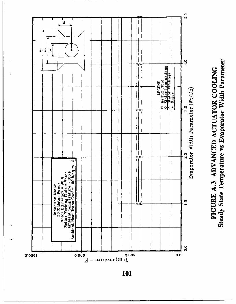
. ,, - ST
zI oo""
o.
0 CO,
00
on
I-I o A- - ,÷ -j 2
I .)I
%..
j - ainlEexadmo
101
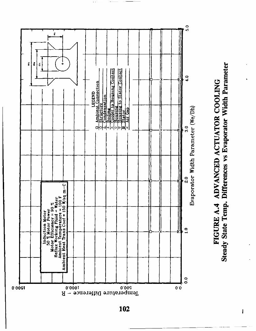
+~ >-0 .- I
00
.- L. t
.0 00E00. 00 CO
010 0 Y 0 t>-3,.
0 LW
C.)0
o>
GIV
&0 u0- z i -4
'
~0
0 g..0
00T0,000! 0,009 0,0- au~ajpaj!( ;anlleadtuu~a
102

01014+
------------------------------------------------<0-----
cu'
00
0909:iio 0 o
U. 0
.j.0
0-01OO O ~0009 0*0
103

900
0 o o o
Ac 0
r 0 0 + ';Im
0 z
00
ONO
E -e000o N.L
- 2
0,09 0*OO 0.) TOi
100

CV2
Z' 0, V. Ao-0-0
-o- - w ~UI
010.00
0
105

0 0
U
M 0
0 00
G* 00 0o c)
1 t.
-4J
1,t3 0
.0 IL
,v-
00
XQ C)
106

0)
/ Q)0 0
C13
0 P
0
- C ---
00.0+
IIt
0,0091~ ~ O*OT00gT
100
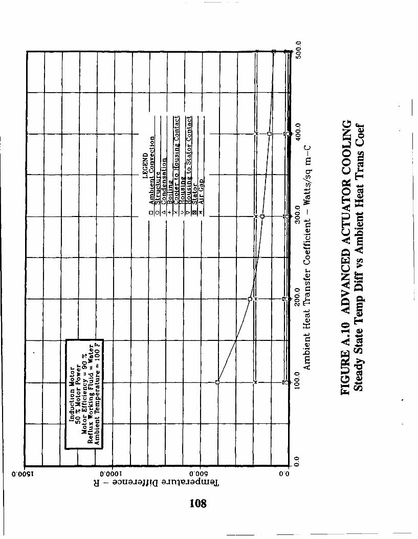
0o
00
00
0 c00 V
-~E-0
o 00
o 0 0
EL. wAL
0 0
X a. U - 45 ON
0-'C E!
4) )
'a-
- m- -aaqp a- e* ~ua
100
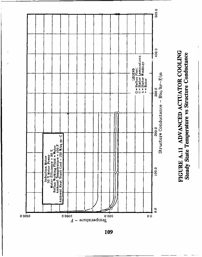
0- - -- - - - - - a 3
0VA
.320 u-..- 0p
11 111 -,E4 &A L
00-0+C-)
-a)
C)2
o
00
10

to 0
00
z >(U
1- 0)4 0 41 -
r rn , .)0
000
.. 0000 0
So
.4-)
0
00
04) ) \ 1
USp
rg.4-)0 0 4) tCq
0
0,09 0-6TU6 00
110
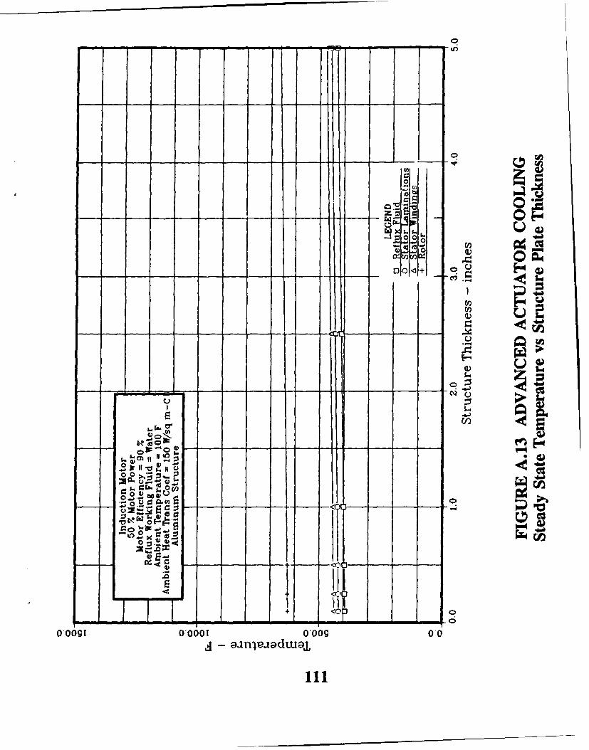
Z 0 0
-~~n o -o + 1
U~t: 0
-0 - 0 E
+ o 0
0,001 0,001 *0090.--------------------------------- - -- .

--
00 I-
0 06M
v .- I.- en S O'
M,40 CI C
two 0
6-0:
0,09 0 ,00 0,0090
;a~~jaj~ ;ajaduj
112)

o.pot
4) rA.u IL
Id 0-
- _ 0•--" "z
• 0XLII
00
to If 0
a,001 oooo0 ooog 00 11 -n
113
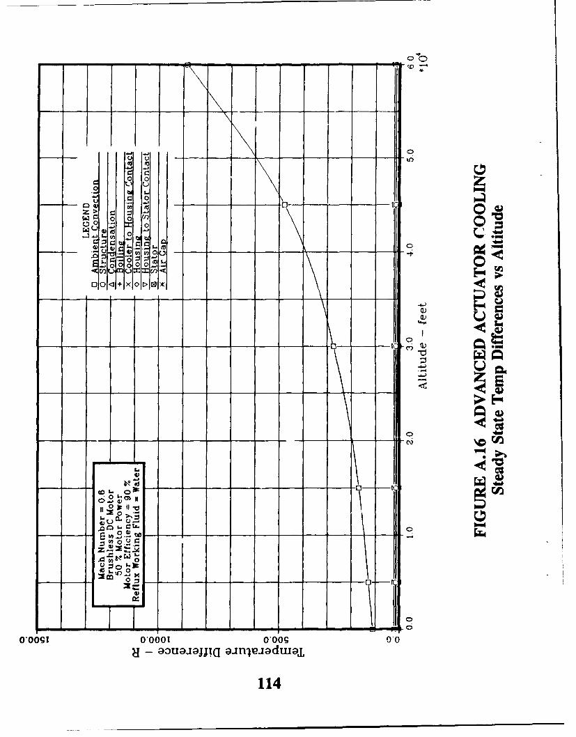
- - , - - - I -
a o
00
C 0
wCu' 0 0 ~"00 o
.2.
O0 old 00
, , u•c#•0 10<+ X ct0 C
00
,0 ,. .•, N
0"
0
- -2
"0*000 0 9 00
114
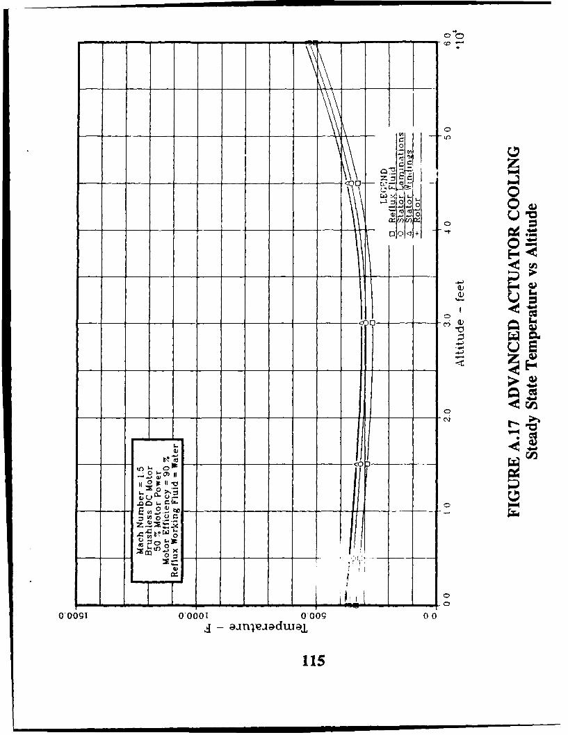
C!
E 3'0a
0 .-e 0, x'U
l--T TI I tii I I vc0,009 0,001 0.6g 0
,4 anjpidwa0
--15
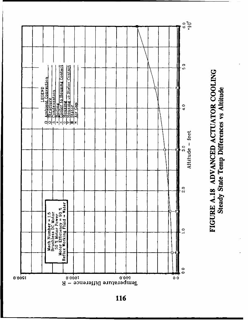
00
C:0
Z >
w - 0 0
0Ct. 0 04Ua
.0 - )V o0 tj- Ol
0o0.01+ x 0 I> 01
ci)
ava
10,
116

_ 0
ol
e• ,"C •.LrL- 0
ZS a--oa:• dao
-3:3- -) 01
0
~~4-A
00
0.00
117
z x

00
00
U C-) 0 U!
r0
0~ 0 --
0 n0
.0 0
zi z 0 .2.5
0 1) a 4.)
00
118-o
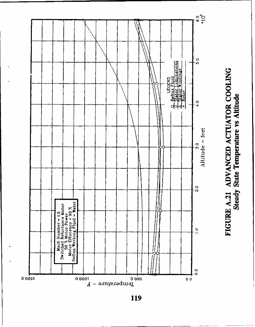
000
o p.
N PC
0 1
"\'a
-------& - r- ..
\.
"X. 1 7 '-so o-
119

.o o
WU -a) 0OG) - 0
S.0000
01 - -0- - -X > 1K
4z4
C4)
0*
.j.
00 0 00o o o
02
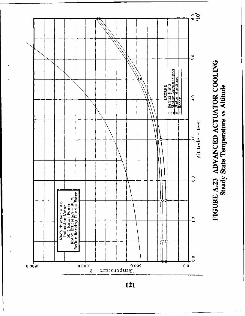
.,0
- -~~~Q. -- ----- - -0'
<0 C0
E
0
-00 L. r. E
- - - -0- to - - - - cQ
0.0
121
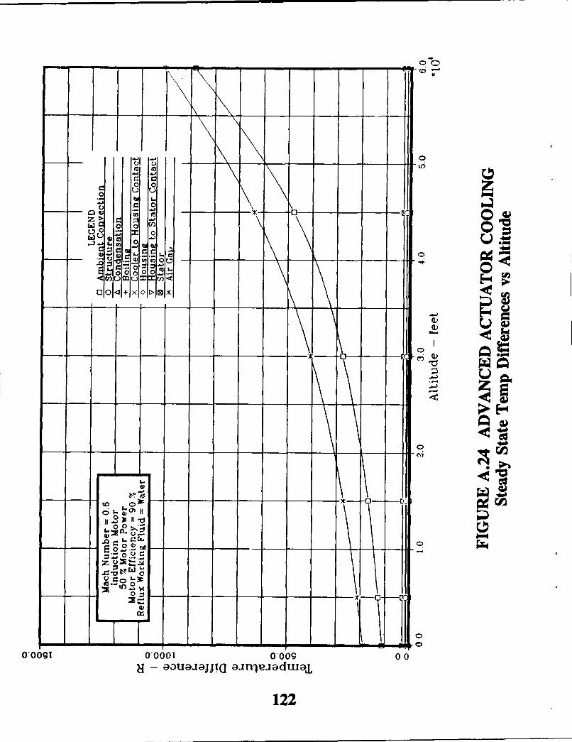
C)o
0 0
u u
o 0
0 z0x0
+~I-
Oa) 0 0 0
! ouCa.00 t
c cn u mu
CC
- 0
(o
0 0 .
C)1
Z IL)
V! ow
00
0(00 0 ,00 0,00 -0
g - 93uai-jj!(I a-n •-adta l-
122
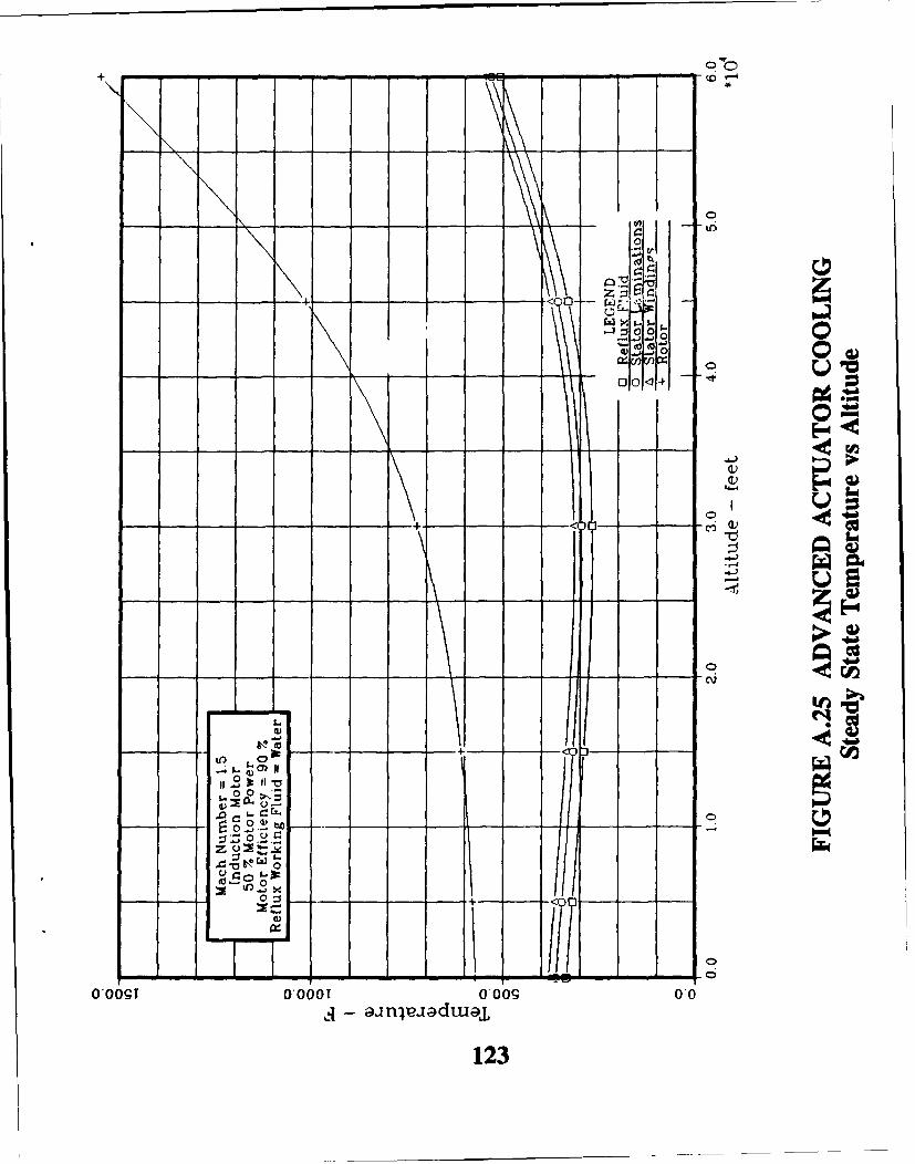
+\ -- - - .- , - (n
*Po
00
, 00
o 0
I f 0
0o0o 0ooo0 ooo0 00_1 - n3
123

0 00
S 0V
o 0 Y
UI. V * Ar- c:- -
000 0 * 0
0om=V. 0!
a-)
- --- ---- ---- ---- ~U
16w
Er-2
z
0
0,09o000o0,0 00
124

- -- - - - ~ * - - ~ ~ ~ - so
- - - - - - - - - - - -
rn
QD 00
04))
OLO 0
000
0.06gi .0601 0009 O-
- -- --w~dtcF.--.---..
125
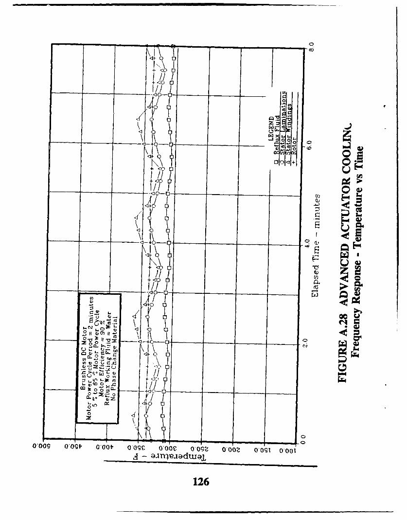
-,6
+ <0 0
j0 /1 /1
0
+<0 0
A/f-•+0 0
cvV0 %0
0ý ZC0
00
4))
C44
0 0
0,009 ,09f, 0,00t 0,09C 0* C. OO z 0 6 009 000
A~
/ T___ _126__
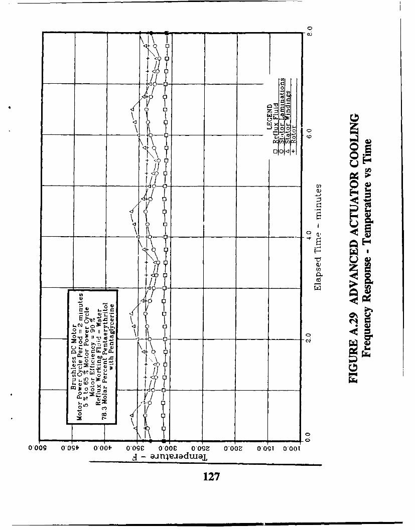
~ ciJ
+~=o o o
n~1~ ~00
I j/ I
1//T
o cu
+ <0 r
C, 0
CL
*.2e 00 =;=
cr~ x1. 5 Ui) L- 0
0 l
0o009 oog9. 0,00f, O0*0C ,00C 0O9ýz 0O06~ -0gI 0-001j - aneaua
127

+
ZZ~o1+
0 0 0 .1-
0 -
S+
2- I $ (I)
' o 0- -.o L
<1+
_ _ _ _ _ _ __ý x_ (I+:2 0
1~128
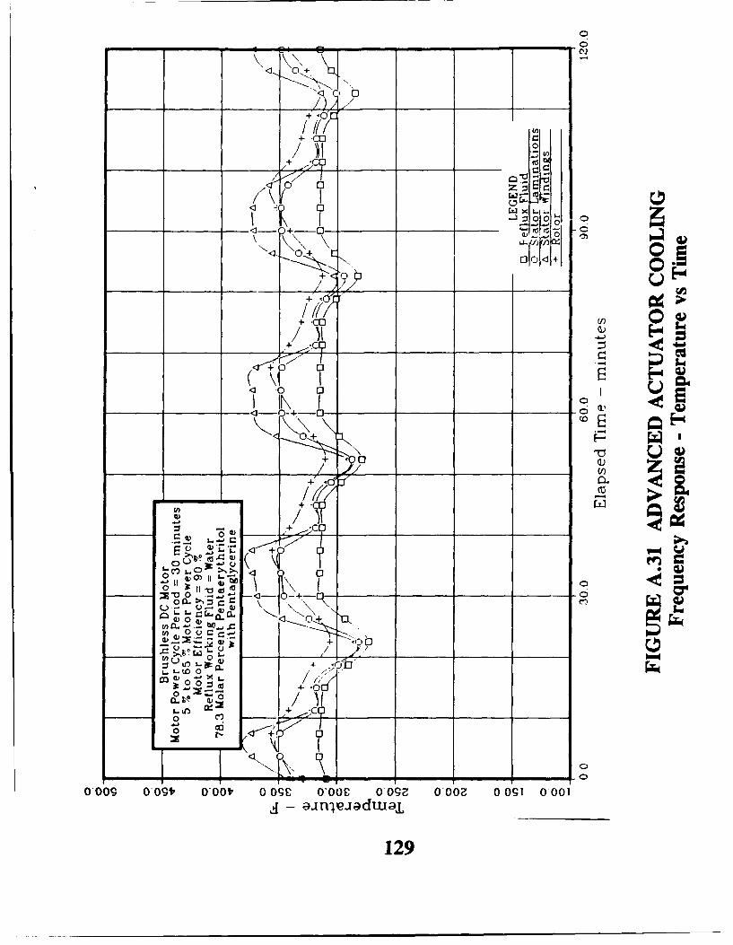
0
K+,
0nW &. -
0~ 0
-~Of o'
/ IV
0+
=-a-o2 - CL +/. _ _ _ _ _ _
00
CO 0)U~'+
- O~-
L.0
0 c
0,009 0 09f, O'OV 0_ 4:" ___C __ 9_002 01 O'
129
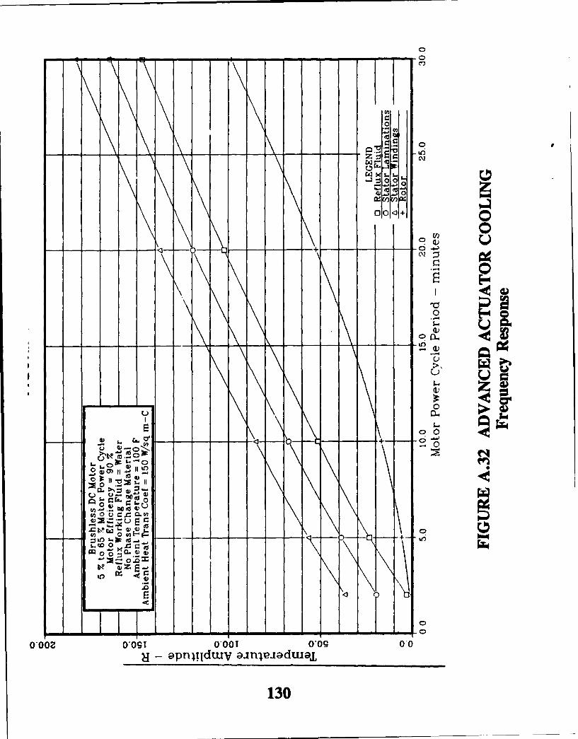
- - -- - - - - - - -- 0ý
0
0.5
V) 0
to
C.) UJ
0 U0
00
-oz o- ac Mtn
co 0 u w
i..( 0 *
lz
0002 0,091 0,001 0*09 0 08 apnl~!TduuV aajpxaJduuaL
130
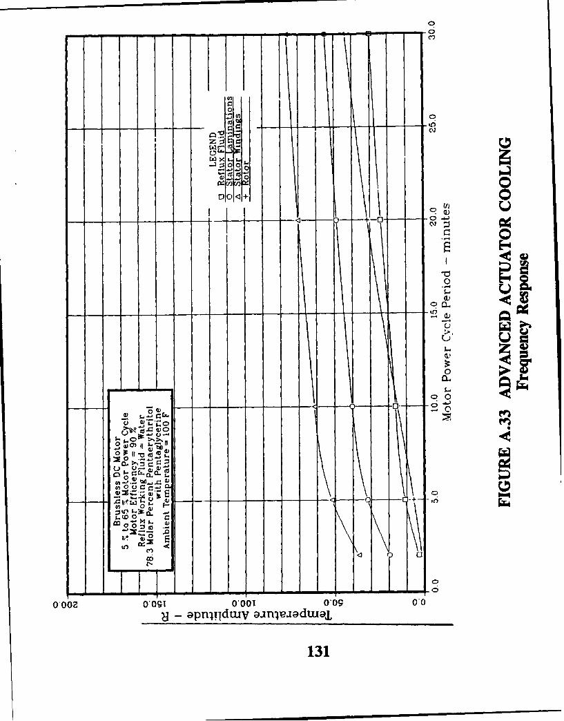
to 0
- ~ ~ ~ ~ 4 to.-as ga a a
0 0l00
.0o V) X
0)
CL,)
CL-
Cl 0 0
-'o -S.-i 0-0 0,0 0-.0apIodu axle Sua
13
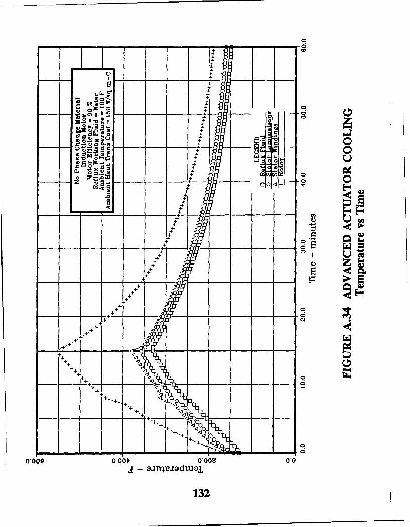
0
-Z10A 4. C
0 : 4-0 %4 4- 0 g
4-
-4. vu 4
040v , Z 4,.. W X 0. , 6
.4- r .,
+4+ 0
z 6 0
2,4- D0+++
+-++. ,
+
E-4.4o-
+
,4- .ne -d ar
+3
+
+..
++ +
+++
t+
* ~z1 4 --- ;74
-~~+ 4++ + -- , - -
0*00 0,0t,0,02 T
+3
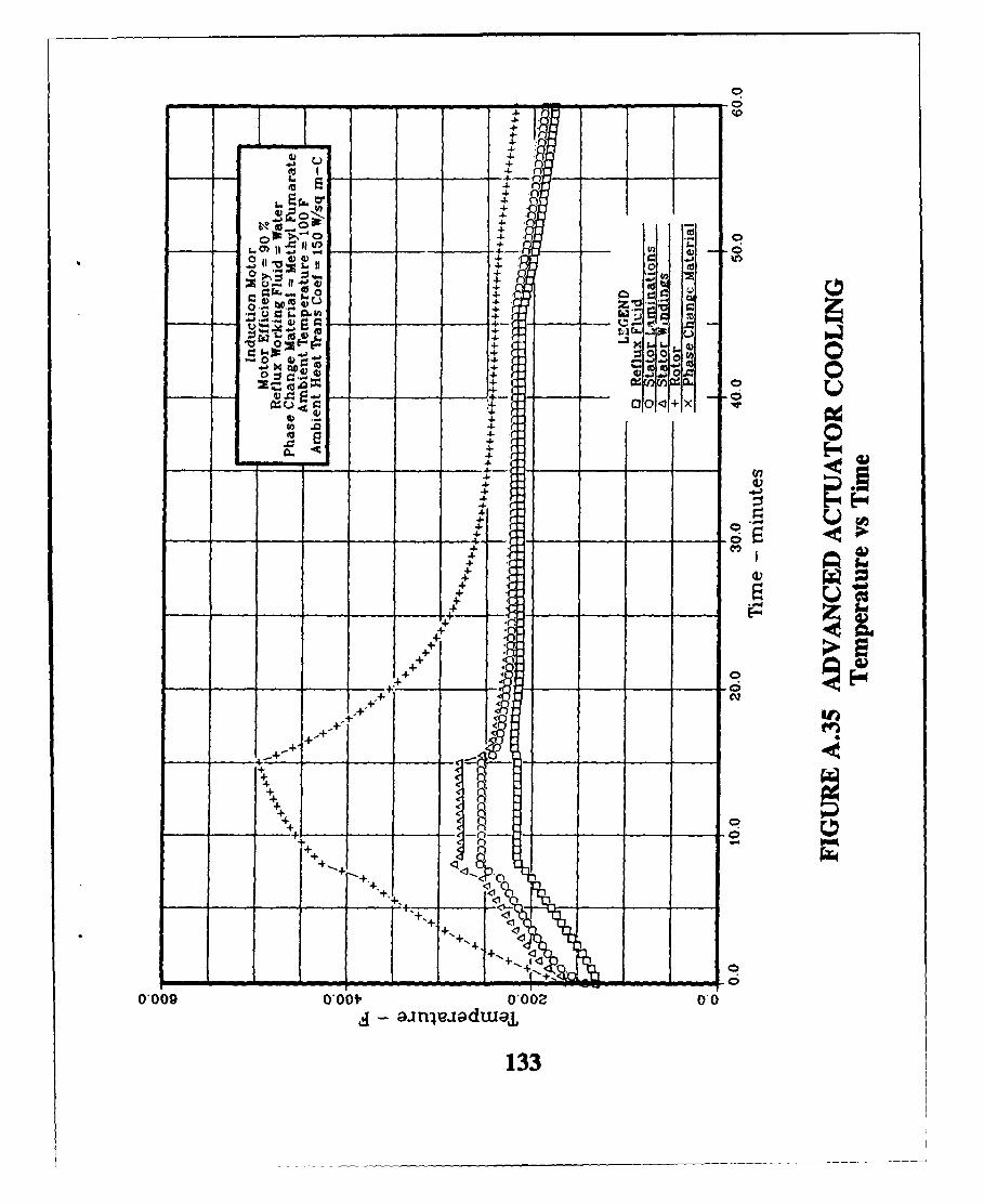
C:- 0
-4-
w OM.EZ+
V ZIE)
0 10--
f U
-
4E
+ I
O '+o
0 *0 0
00,q aij d aj
1333

Or 0
I- 0
00*
0 a_
0
-1140
o ~C)
0a(0Pl.
0 cc
U)W
cq4
O-T 6'0 9*0 C0 9*0 T0 CtO 2*0 VO 1 0"0uoilo3e~ ssle${ pinbirj Y9d
134
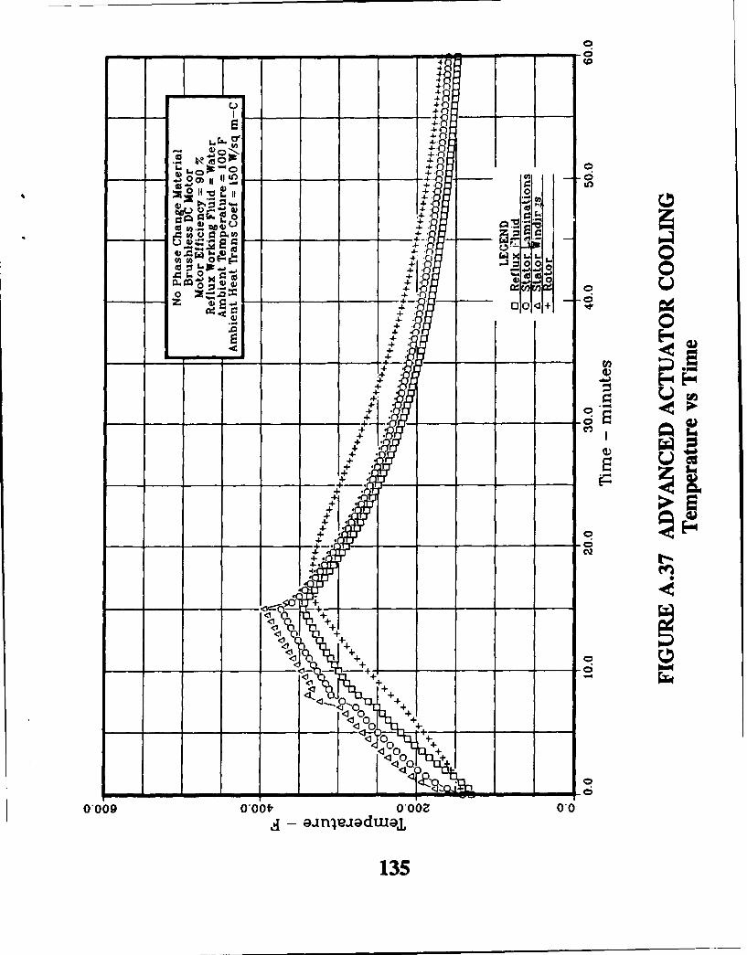
00
04
-4-f
-4-f 0- -~4- f0
4 ~II'~ii010+
0 0
o ~~-*-.4-4-Z - - ~o+ ~ ~.6
+0
-4-++4-.
.4-
++
+
4-
_ 4..4-.
- 4C.
-4.'C%
<1__ -*I
0 +
0.009 0,00f,, 0.00Z 0*0
135

4. - -6
-4.0 ~~4. 0 e
.4 Z0-4-w
U- 00
4. so- . : t
:30 V)0
or 600 0+
C,)ca
4-4
.4.4a4 d
4-..4-.
.4-.
-4-.c
4-.
4-.
+-
1--<1
0
136

to0
00
GO _ 0 0 Q
04)0
C0.0.u
01i 606 906 Z6 906 9o to C-6 Z-6 TO 0 0uoqo-e.U ssvW plnbil yW3d
137

4-1
4-0 _
.L4.
-4-0
0 j -4-f
_, 4-0__ 4-'-.r -6
4-0
4 0
a- 0L to 0 . 0400 -1. 0-
c O I ) 4- 0Z
=1 0
0~ ~
4--4- 9
4-4- 1
4- *4. -
4- :4- *
+
+ -0
+
++
+<0
+ +<++<
+ <+
++
4+fil~~~ -<J-0-__ ___
4-4-d 0
4.00
.<' 0-
0*009 0,00f, 0*00 0,0- anva~dtuaj,
138
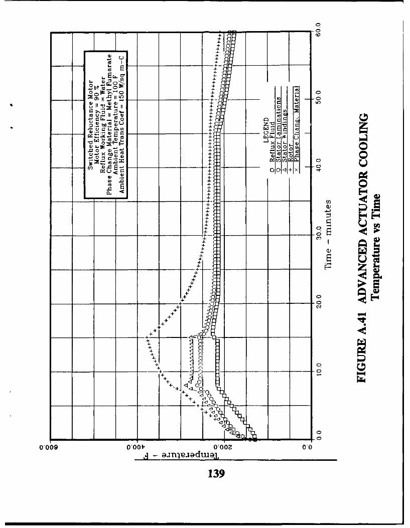
0
-4-.
-4.4-C
I -4-4._
o4-( 4.
w -4- C-
-r. 1. C4 .- 0
- __ -'4-. E4 ) E 0td 4-.
0II 4-C
-::4- :3 0 00 V) 0:34- 0.2O
+ Cn
4-
4-
4 -4-4-
______ .o
r
-4- --
4 1-S4-4 -.
4-
r
r
14-
'4- rC).
4- r - *) -
++-4-4F
+- CV
+
++
++ <1
o-oo4 -
413

00
0-
=;= M.0wr. E-
01l 6*0 9*0 to 90 9,0 tO CO Z'O TO 0,0uorloeiu ssle pTnbirl W3d
140
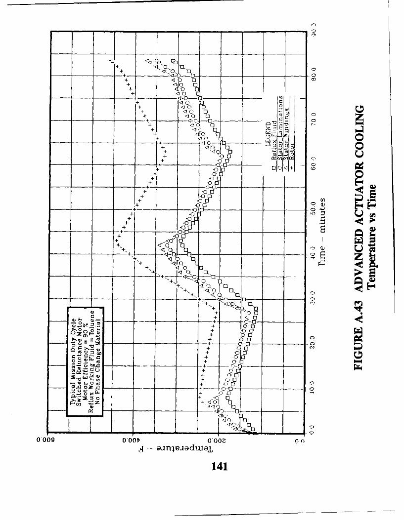
•-0C O4- 0 0
-4- -- ~ <10-0-- 04 10
+ 110 0
E-- l "1
+ 10 0 z+ 00
+ <10 <1
+1 00
-. 04
+:r~ 0oo0014
+~~~~~- o0 _ _ _ _
+ 000++0
+ '00 02 .0.0
+ -0
+ýT J +
+ 0
02= +-
C +
0,009 0, 0f - -
141 0
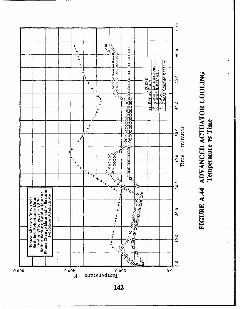
+ A"10 0
-4- <'-0 0+ '10 0+ (D0 0+ '0 0
4- '10 0 .
_ _ + - -0 0 (a+ '0 0
4- '0 0+ '10 0 . -
+ '0 04- '1 0 0 x
-4-0 '1 04=- <1 0
40 -'1-0 0 XL 2G
+ 0.0-- -++
+ *0)0-4- .0 0f ý 4
+ -0 0
+ 1 0,0a
'10 10 0 C
0 0 >
00
.0
0 0
+ 0)0 + )004-
-0) .. 0( ~%0 00
0...-ý 0 0
Q '10
-+ - - .0 . , -Cp+ 0 0o
- - - + -*o - -
0009 00t +0O 00
+ -0
M V 0 +142
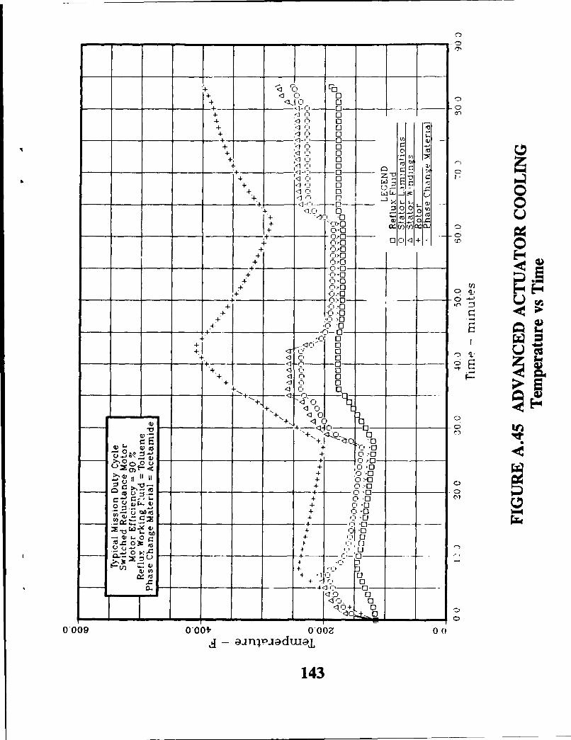
<10 Pa+ <0 0+ <L11 ( 0
-4--- -0 0-+ 10 0 e+ <0 0
-1-+- V)
+ ilD c ,
+ 'D 0C+ 0 V
-+ <1 -1 0
(:)0 2
+ 0
+> :3-'-0
0+ 01.)-c
+ ~r0'01.10o 0
4 010
7++0 .0+ <10 , 0n
:k+~- -- X++ 10 ,-
+ 1-0 0+ lK
+1+
<1 0 0 F0
+ 00
++ 1 0
IV 1 :3 0- 0-ko 2- ---- 0 -'0-
-I 'L + 0,-0+- n LI
-. ~~~~~ 0 .. 0,______ __
o~. -- - + .0'I -04-~ 010
r + . 0010+u .0
W -X 4) 0-
000 001 r'0+ 000
0~ -0
143
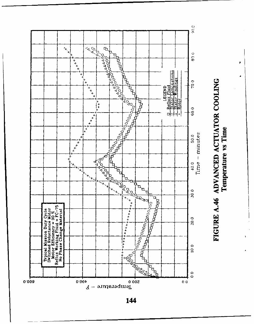
+
+ 0 0"+ 40 0 -
+ 0 0
+ 0
<100
.10t
0 0004) ý( W 00
+ *0C0I+ '
+ (Ii
+ *0
0: 0to
---- - ! - __ _
b N 9
++0
++
0
LO + jf . 0
L). +_0 __
_ _ _ _ _ 0
0009+ 000 0OZ0
1441

+ 0 0
+ 0 0
0-0 0+ 0 0+ 0 0
4 +10 0+ ~ 0 0 .0 ro+ 10 0 -V
+ 0 01 IV0 bi
<_ 0_ O
0 0o+ 0< XO 0n01+Ji
%X> 0
+ oxo+ OXO
+ .0x0
+ 0-0 XIJ
+ .0 x,0
- --4--.0- < 0 -+ .0X
_~~ _ .0 _ 0++ S 0 >0
+ d1•) 010-- 0 oQ)
-~ - 4 10 -0 -
Q0 0Id 0
o0 0
++
+ OX0
,V + 0 XO
00
000+ 000 Y00 0
:j + 145
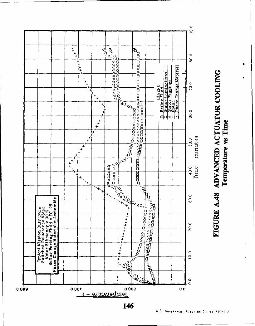
+i :),0 0+ o C
-0-0+ f 0
+ .1 10 0 mZ. 0
4 10. 0
+1 <1 0 0
4-0 0 X40
+ o- + 0x- 0 0ýýo+ a10>10
+ 0>1o+ .0 X 0 _ _
+ .0 X0
+-0 >0 G-.0 0
510 00 c0 0
0- 0- _ _ - ___ +' 0
___0 0_ _ __ __ _q~
+ 00X
+ 0 X0-~~+ -_ _ - - C >
L)=m -0 YO0Zý 4) H 0 v0
+ x 0 CD0
+ 0>+ a , 10-4 0 -,
cox0
0 tio
0009 rO. 0 OO 0 1I0 4 + -0 >
+1S GOENEN0R-0N FIE 5-1