ELEC HL Series DVR User Manual · ELEC HL Series DVR User Manual ......
55
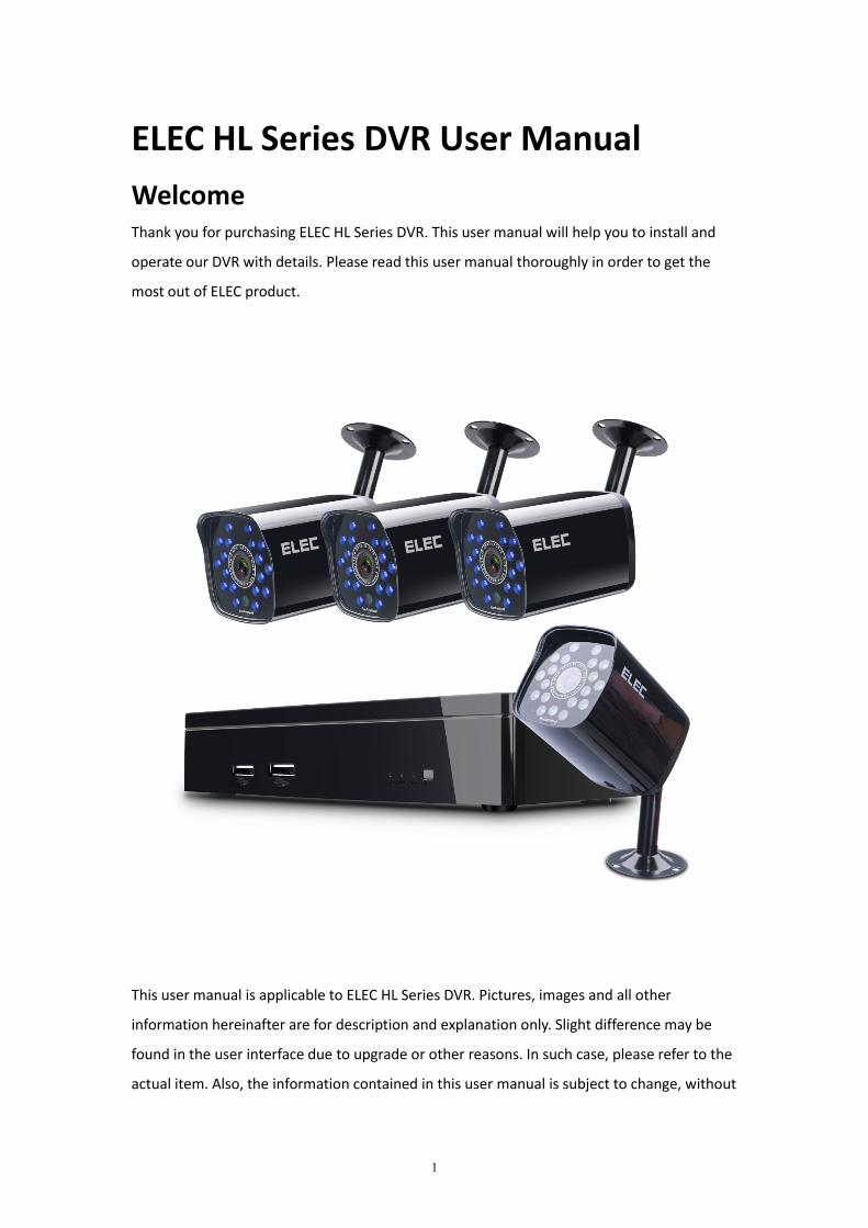
1 ELEC HL Series DVR User Manual Welcome Thank you for purchasing ELEC HL Series DVR. This user manual will help you to install and operate our DVR with details. Please read this user manual thoroughly in order to get the most out of ELEC product. This user manual is applicable to ELEC HL Series DVR. Pictures, images and all other information hereinafter are for description and explanation only. Slight difference may be found in the user interface due to upgrade or other reasons. In such case, please refer to the actual item. Also, the information contained in this user manual is subject to change, without
Transcript of ELEC HL Series DVR User Manual · ELEC HL Series DVR User Manual ......
1
ELEC HL Series DVR User ManualWelcomeThank you for purchasing ELEC HL Series DVR. This user manual will help you to install and
operate our DVR with details. Please read this user manual thoroughly in order to get the
most out of ELEC product.
This user manual is applicable to ELEC HL Series DVR. Pictures, images and all other
information hereinafter are for description and explanation only. Slight difference may be
found in the user interface due to upgrade or other reasons. In such case, please refer to the
actual item. Also, the information contained in this user manual is subject to change, without
2
notice, due to upgrade or other reasons. To check the latest version of ELEC HL Series DVR,
please visit our website www.elec.com
Should you have any questions or concerns, please contact our support team by emailing
[email protected] or sending messages to our Skype account: ELEC System Support.
Important1. When the DVR package arrived, please check it and make sure that you received every
component.
2. The VGA cable and HDMI cable mentioned below are not included in our DVR package.
3. Not all our DVRs come with a hard drive. If the model you ordered doesn't include a hard
drive, please purchase a compatible HDD by yourself.
4. The remote controller is not supported by HL Series DVR.
5. Improper installation or usage may cause severe damage. Please install and operate the
DVR under the guidance of ELEL user manual.
6. The DVR should be placed horizontally instead of vertically.
Warnings1. Do not connect several DVRs to one power strip as overload could cause overheating or a
fire hazard.
2. Make sure ELEC DVR is working under the rated voltage. For DVR, the rated voltage is 5V.
For cameras, the rated voltage is 12V.
3. Do not place heavy objects on DVR.
4. Do not disassemble, repair, or replace the DVR by yourself since the ELEC company will
not take responsibility that caused by such behaviors.
5. Do not unplug the device while it is running to prevent video loss and other abnormalities.
6. Do not smash, slam, shake the DVR intensively. And keep the device away from magnetic
interference.
7. In order to extend the life of the DVR, please keep it away from water, heat, and dust,
direct sunlight, and put it in a well-ventilated place.
8. Please clean the housing regularly using a dry soft cloth. Use neutral detergent, instead of
alkaline detergents, to clean the housing when the dirt is hard to remove.
3
Table of Contents
Chapter 1. Introduction.............................................................................................................. 4
Chapter 2. Installation.................................................................................................................4
2.1 Front Panel.................................................................................................................... 5
2.2 Rear Panel......................................................................................................................6
2.3 Proper Cable Connection.............................................................................................. 7
2.4 Soft Keyboard................................................................................................................9
Chapter 3. Getting Started........................................................................................................10
3.1 Start up DVR................................................................................................................ 10
3.2 Shut Down DVR........................................................................................................... 10
3.2.1 Standard Shutdown..........................................................................................10
3.2.2 Forced Shutdown..............................................................................................11
3.3 Reboot.........................................................................................................................11
Chapter 4. Startup Wizard........................................................................................................ 11
Chapter 5. Login........................................................................................................................12
5.1 Login............................................................................................................................ 13
5.2 Logout..........................................................................................................................13
5.3 Account Lockout..........................................................................................................13
Chapter 6. Live View................................................................................................................. 14
Chapter 7. DVR Main Menu Guide........................................................................................... 14
7.1 Playback.......................................................................................................................15
7.1.1 Steps for Playback.............................................................................................15
7.1.2 Playback Toolbar Introduction......................................................................... 16
7.2 Record Mode...............................................................................................................17
7.2.1 Digital................................................................................................................17
7.2.2 Backup.............................................................................................................. 17
7.2.3 Record...............................................................................................................18
7.2.4 HDD Manage.....................................................................................................20
7.3 System Info (the upside down exclamation mark of “!”)............................................22
7.3.1 HDD Info........................................................................................................... 23
7.3.2 LOG................................................................................................................... 23
7.3.3 Version..............................................................................................................23
7.3.4 Online User.......................................................................................................23
4
7.4 Startup Wizard............................................................................................................ 23
7.5 Alarm Setting...............................................................................................................23
7.5.1 Alarm Set.......................................................................................................... 24
7.5.2 Abnormality......................................................................................................26
7.6 Setting......................................................................................................................... 26
7.6.1 General............................................................................................................. 27
7.6.2 Video.................................................................................................................27
7.6.3 Account.............................................................................................................30
7.6.4 RS232................................................................................................................ 31
7.6.5 Advanced.......................................................................................................... 31
7.7 Network Setting.......................................................................................................... 33
7.7.1 Network............................................................................................................34
7.7.2 Net Service........................................................................................................36
7.7.3 Cloud Service.................................................................................................... 41
7.7.4 EMAIL................................................................................................................41
Chapter 8. Shortcuts................................................................................................................. 42
8.1 Vertical Shortcuts........................................................................................................42
8.2 Horizontal Shortcuts....................................................................................................43
8.2.1 Close Record..................................................................................................... 44
8.2.2 Playback............................................................................................................44
8.2.3 PTZ Setting........................................................................................................44
8.2.4 Color Setting..................................................................................................... 47
8.2.5 Hide...................................................................................................................47
Chapter 9. Remote Control.......................................................................................................47
9.1 Remote Access on PC.................................................................................................. 48
9.2 Remote Access on Mobile Phone................................................................................49
9.3 Remote Control on the Web.......................................................................................50
9.4 Remote Control on CMS..............................................................................................52
Chapter 10. Appendix............................................................................................................... 55
Chapter 1. IntroductionELEC HL DVR is an excellent digital monitoring equipment that’s designed for security
protection. It has embedded the LINUX operating system which is more stable. Armed with
standard H.264 codec and unique spatial and temporal filtering algorithm, ELEC DVR realizes
5
the synchronized video monitoring of high image quality and low data rate. Moreover, its
powerful network service function enormously enhances the network data transmission
capability and remote control ability.
As a safe and protection system, you can expect remote control, recording & playback, and
backup, motion detection, alarm linkage, etc from ELEC HL DVR.
Chapter 2. InstallationPlease be acquainted with ELEC HL DVR installation and its components first.
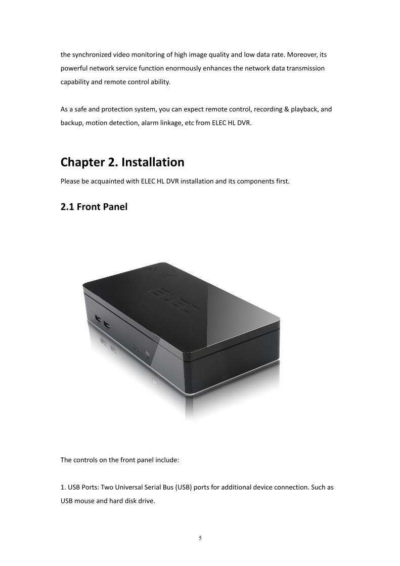
2.1 Front Panel
The controls on the front panel include:
1. USB Ports: Two Universal Serial Bus (USB) ports for additional device connection. Such as
USB mouse and hard disk drive.
6
2. Power: Power indicator switches to red when the DVR is powered on.
3. HDD: HDD indicator switches to green when the hard drive is active.
4. Record: Record indicator flashes rapidly (green) when the DVR is recording.
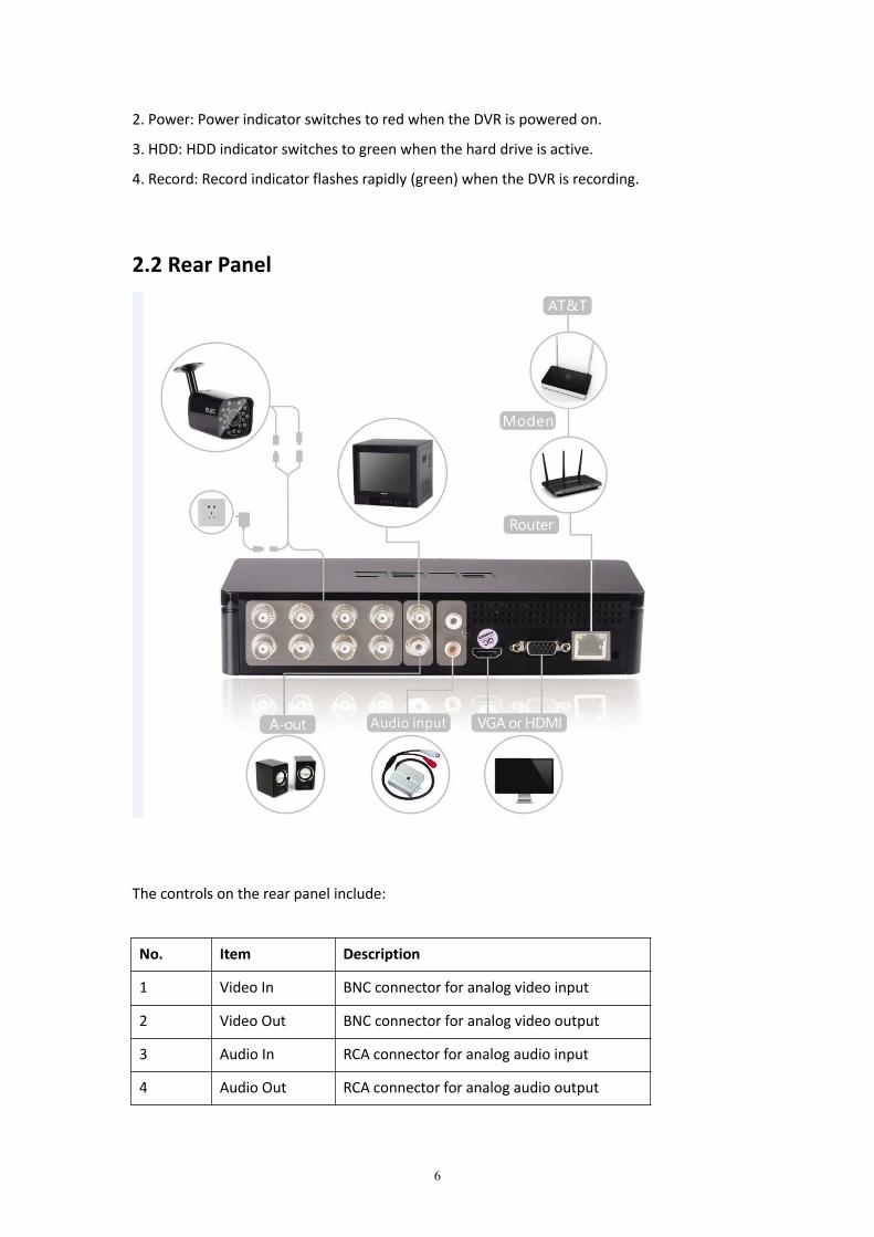
2.2 Rear Panel
The controls on the rear panel include:
No. Item Description
1 Video In BNC connector for analog video input
2 Video Out BNC connector for analog video output
3 Audio In RCA connector for analog audio input
4 Audio Out RCA connector for analog audio output
7
5 HD-Out HD output connector
6 VGA VGA interface for monitor connection
7 Network RG45 network connector for internet
connection8 DC DC power input connector
2.3 Proper Cable Connection
Step 1: Connect monitor (TV Set, PC Monitor, etc) to DVR by VGA/HDMI/BNC cable.
Note:
1. If you connect TV set by HDMI or VGA cable, please make sure that you switch TV set to
corresponding HDMI or VGA input mode (also called RGB or PC in some TV sets).
2. You can only view screen after connected TV, HDMI or VGA monitor. HDMI or VGA is
recommended. The minimum requirement for resolution is 1024*768.
3. All our DVRs are like stand alone computers, so you SHOULD NOT directly connect them to
your computer.
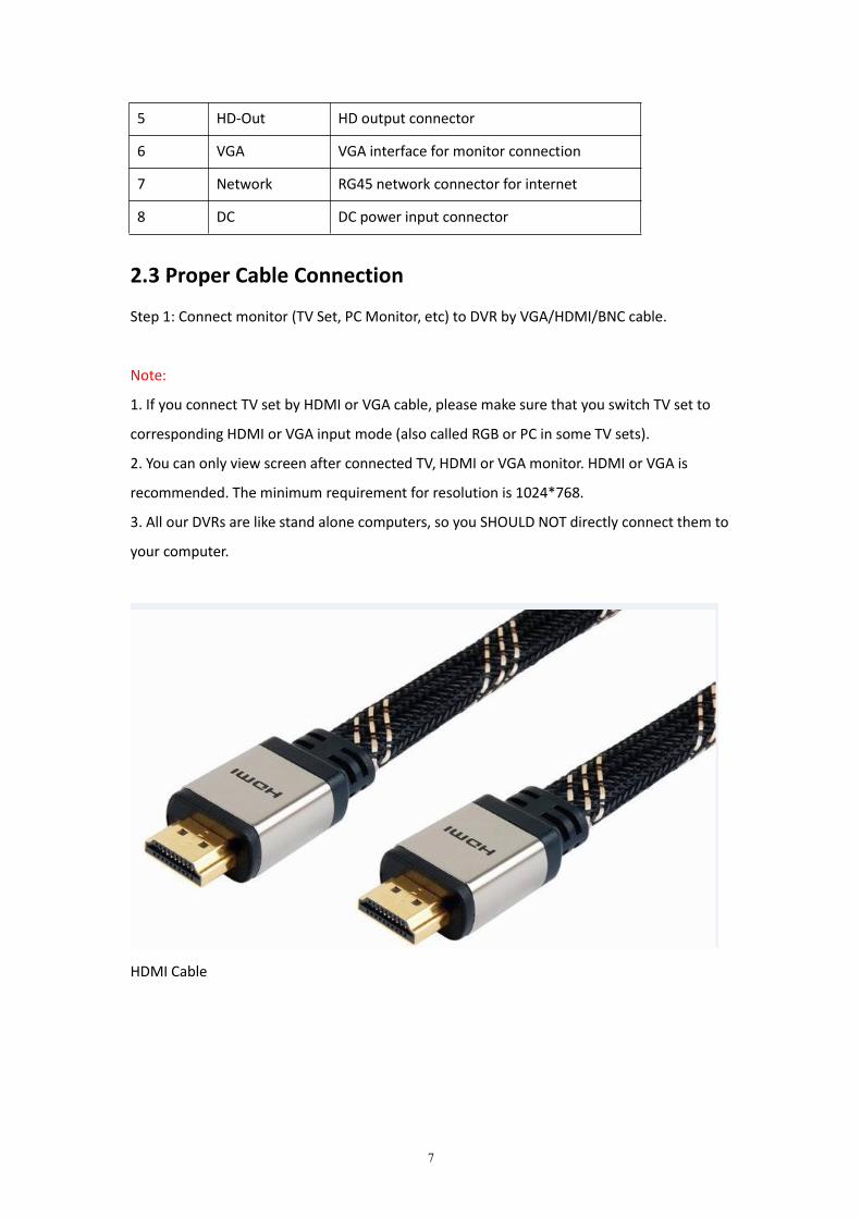
HDMI Cable
8
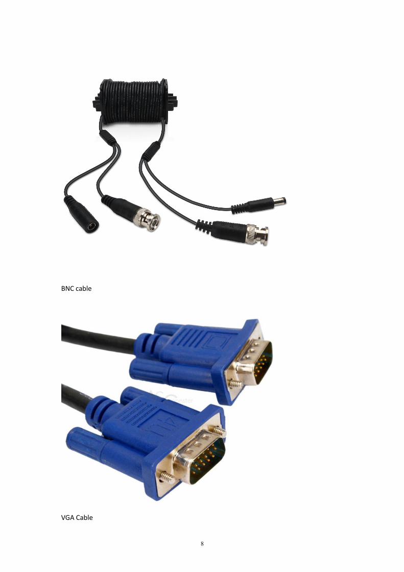
BNC cable
VGA Cable
9
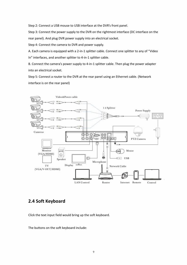
Step 2: Connect a USB mouse to USB interface at the DVR’s front panel.
Step 3: Connect the power supply to the DVR on the rightmost interface (DC interface on the
rear panel). And plug DVR power supply into an electrical socket.
Step 4: Connect the camera to DVR and power supply.
A. Each camera is equipped with a 2-in-1 splitter cable. Connect one splitter to any of “Video
In" interfaces, and another splitter to 4-in-1 splitter cable.
B. Connect the camera’s power supply to 4-in-1 splitter cable. Then plug the power adapter
into an electrical socket.
Step 5: Connect a router to the DVR at the rear panel using an Ethernet cable. (Network
interface is on the rear panel)
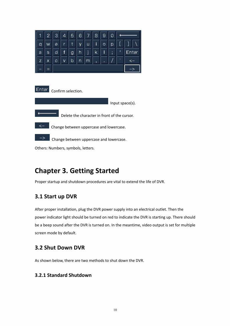
2.4 Soft Keyboard
Click the text input field would bring up the soft keyboard.
The buttons on the soft keyboard include:
10
Confirm selection.
Input space(s).
Delete the character in front of the cursor.
Change between uppercase and lowercase.
Change between uppercase and lowercase.
Others: Numbers, symbols, letters.
Chapter 3. Getting StartedProper startup and shutdown procedures are vital to extend the life of DVR.
3.1 Start up DVR
After proper installation, plug the DVR power supply into an electrical outlet. Then the
power indicator light should be turned on red to indicate the DVR is starting up. There should
be a beep sound after the DVR is turned on. In the meantime, video output is set for multiple
screen mode by default.
3.2 Shut Down DVR
As shown below, there are two methods to shut down the DVR.
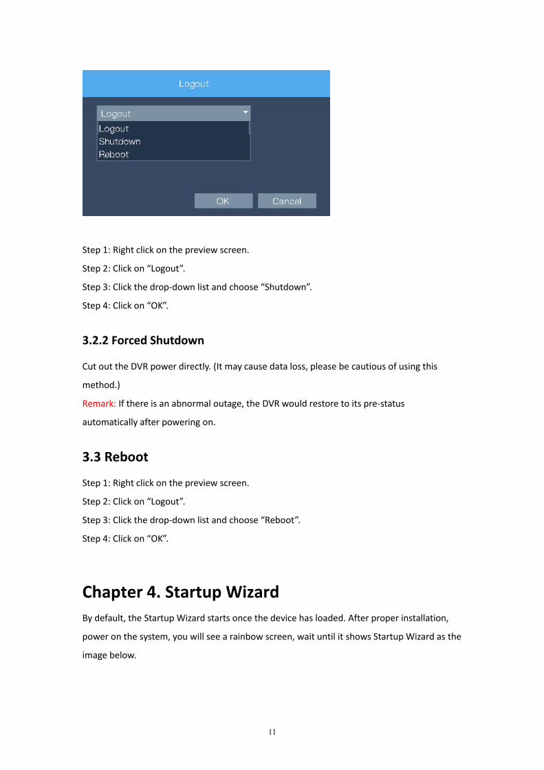
3.2.1 Standard Shutdown
11
Step 1: Right click on the preview screen.
Step 2: Click on “Logout”.
Step 3: Click the drop-down list and choose “Shutdown”.
Step 4: Click on “OK”.
3.2.2 Forced Shutdown
Cut out the DVR power directly. (It may cause data loss, please be cautious of using this
method.)
Remark: If there is an abnormal outage, the DVR would restore to its pre-status
automatically after powering on.
3.3 Reboot
Step 1: Right click on the preview screen.
Step 2: Click on “Logout”.
Step 3: Click the drop-down list and choose “Reboot”.
Step 4: Click on “OK”.
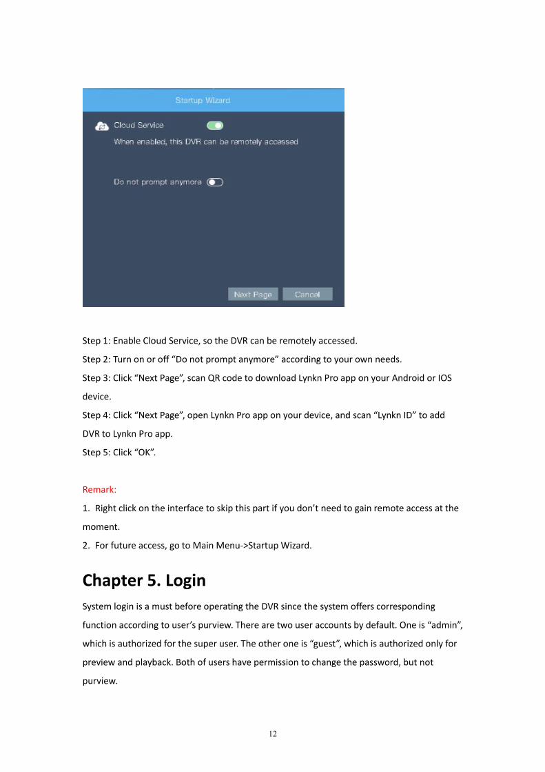
Chapter 4. Startup WizardBy default, the Startup Wizard starts once the device has loaded. After proper installation,
power on the system, you will see a rainbow screen, wait until it shows Startup Wizard as the
image below.
12
Step 1: Enable Cloud Service, so the DVR can be remotely accessed.
Step 2: Turn on or off “Do not prompt anymore” according to your own needs.
Step 3: Click “Next Page”, scan QR code to download Lynkn Pro app on your Android or IOS
device.
Step 4: Click “Next Page”, open Lynkn Pro app on your device, and scan “Lynkn ID” to add
DVR to Lynkn Pro app.
Step 5: Click “OK”.
Remark:
1. Right click on the interface to skip this part if you don’t need to gain remote access at the
moment.
2. For future access, go to Main Menu->Startup Wizard.
Chapter 5. LoginSystem login is a must before operating the DVR since the system offers corresponding
function according to user’s purview. There are two user accounts by default. One is “admin”,
which is authorized for the super user. The other one is “guest”, which is authorized only for
preview and playback. Both of users have permission to change the password, but not
purview.

13
5.1 Login
No password has been set for both of the users. When the login interface shows up, choose
the User Name, leave the password field empty, then click “OK”.
5.2 Logout
Step 1: Right click on the preview screen.
Step 2: Click on “Logout”.
Step 3: Click on “OK”.
5.3 Account Lockout
Password protection: The DVR shall activate account lockout after inputting the wrong
password consecutively for 7 times (Unlock the account automatically after reboot or half an
hour).
Please change the User Name and password timely in “Account” field for safety. (To change
User Name and password, please refer to 7.6.3)
14
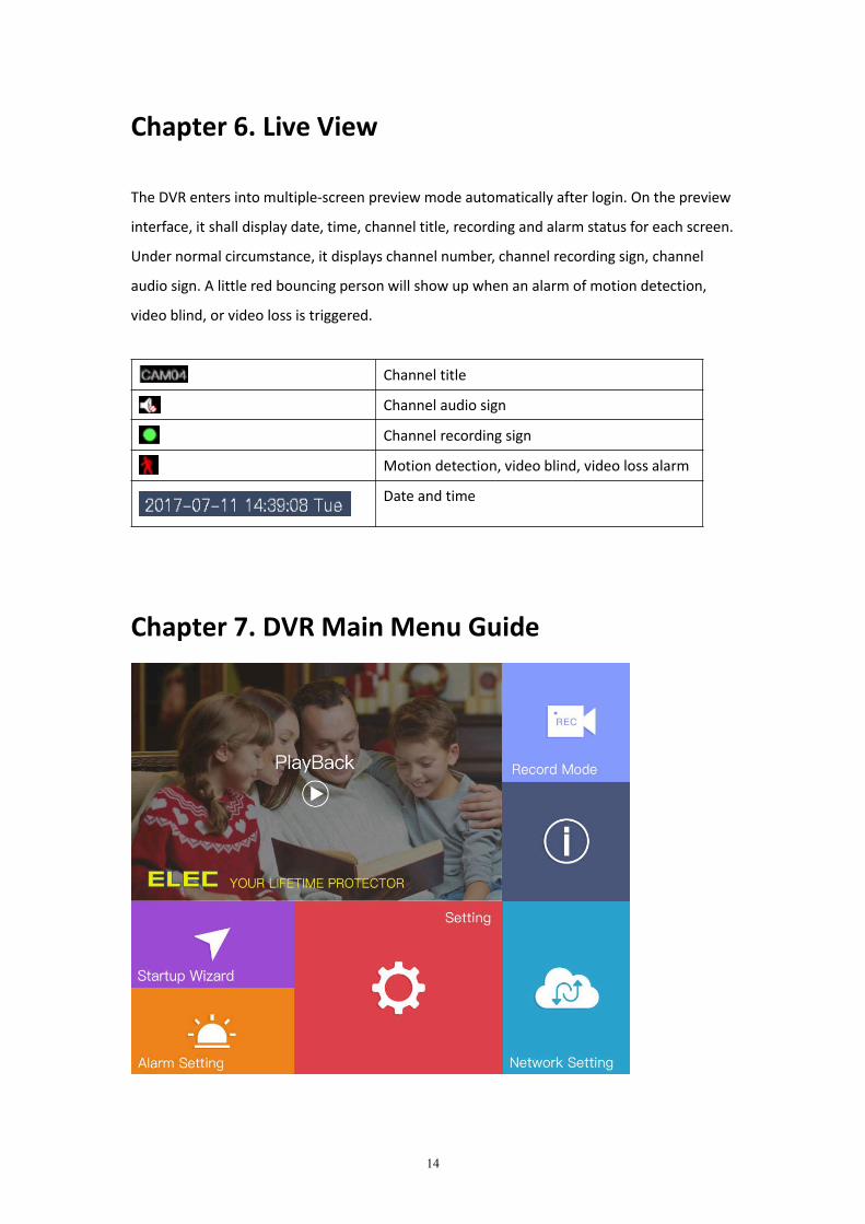
Chapter 6. Live View
The DVR enters into multiple-screen preview mode automatically after login. On the preview
interface, it shall display date, time, channel title, recording and alarm status for each screen.
Under normal circumstance, it displays channel number, channel recording sign, channel
audio sign. A little red bouncing person will show up when an alarm of motion detection,
video blind, or video loss is triggered.
Channel title
Channel audio sign
Channel recording sign
Motion detection, video blind, video loss alarm
Date and time
Chapter 7. DVR Main Menu Guide

15
Right click on the preview screen, click on “Main Menu” to view different operations of ELEC
HL Series DVR. Check each operation below.
Remark:
1. If you need to exit from a certain page, just right click on the screen.
2. Please click “OK” after setting to save the configuration.
7.1 Playback
Path: Main Menu->Playback
In this field, you can search for records, play back records, etc.
7.1.1 Steps for Playback
Step 1: Right click on the preview screen. Go to Main Menu->Playback.
Step 2: Click “Read/Write” on the top corner.
Step 3: Search for the recorded video.
You can use the date, channel and record mode (All, Regular, Alarm, Manual) to filter the
recordings.
Step 4: Find the needed playback file and view it.
16
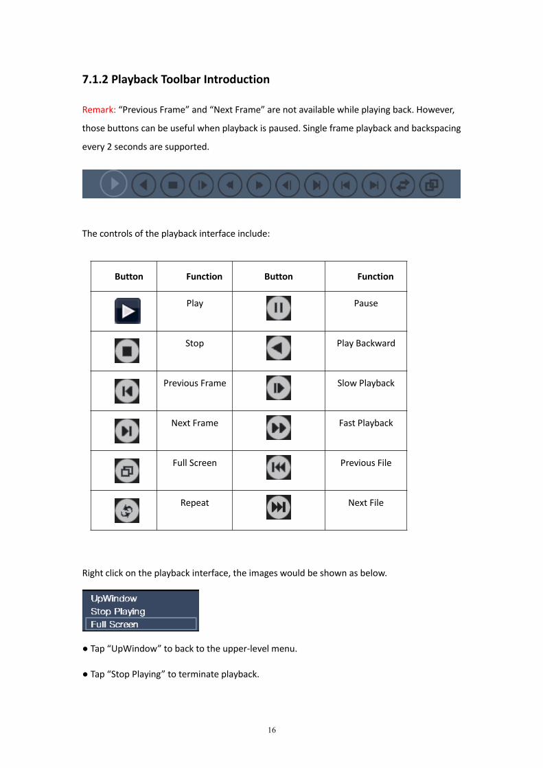
7.1.2 Playback Toolbar Introduction
Remark: “Previous Frame” and “Next Frame” are not available while playing back. However,
those buttons can be useful when playback is paused. Single frame playback and backspacing
every 2 seconds are supported.
The controls of the playback interface include:
Button Function Button Function
Play Pause
Stop Play Backward
Previous Frame Slow Playback
Next Frame Fast Playback
Full Screen Previous File
Repeat Next File
Right click on the playback interface, the images would be shown as below.
● Tap “UpWindow” to back to the upper-level menu.
● Tap “Stop Playing” to terminate playback.
17
● Tap “Full Screen” to playback in full-screen mode
7.2 Record Mode
Path: Main Menu->Record Mode
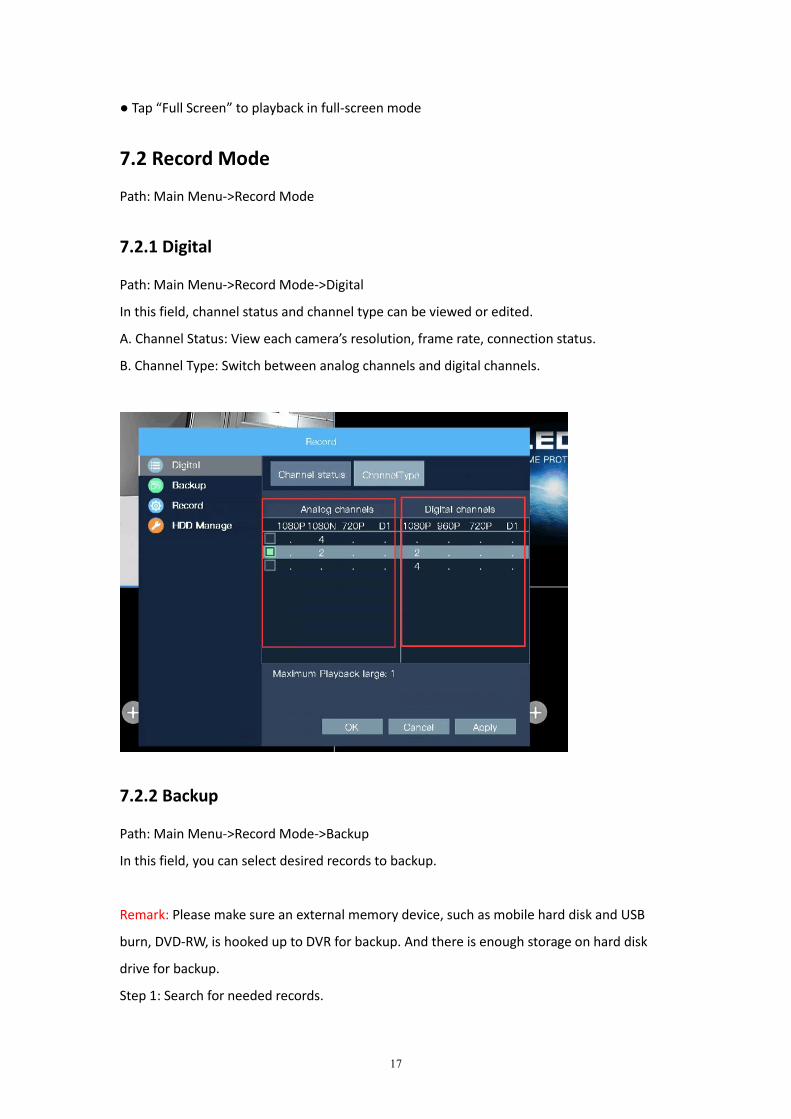
7.2.1 Digital
Path: Main Menu->Record Mode->Digital
In this field, channel status and channel type can be viewed or edited.
A. Channel Status: View each camera’s resolution, frame rate, connection status.
B. Channel Type: Switch between analog channels and digital channels.
7.2.2 Backup
Path: Main Menu->Record Mode->Backup
In this field, you can select desired records to backup.
Remark: Please make sure an external memory device, such as mobile hard disk and USB
burn, DVD-RW, is hooked up to DVR for backup. And there is enough storage on hard disk
drive for backup.
Step 1: Search for needed records.
18
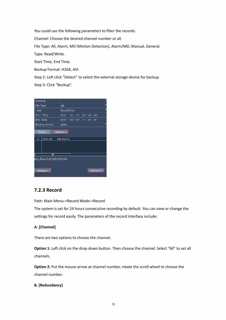
You could use the following parameters to filter the records.
Channel: Choose the desired channel number or all.
File Type: All, Alarm, MD (Motion Detection), Alarm/MD, Manual, General.
Type: Read/Write.
Start Time, End Time.
Backup Format: H264, AVI.
Step 2: Left click “Detect” to select the external storage device for backup.
Step 3: Click “Backup”.
7.2.3 Record
Path: Main Menu->Record Mode->Record
The system is set for 24 hours consecutive recording by default. You can view or change the
settings for record easily. The parameters of the record interface include:
A. [Channel]
There are two options to choose the channel.
Option 1: Left click on the drop-down button. Then choose the channel. Select “All” to set all
channels.
Option 2: Put the mouse arrow at channel number, rotate the scroll wheel to choose the
channel number.
B. [Redundancy]
19
This function allows you to double backup recorded files, which equals to record the video
into the two hard disks. Under such circumstance, the DVR needs to be installed with 2 hard
disks simultaneously. One is the read/write disk, the other one is redundant disk.
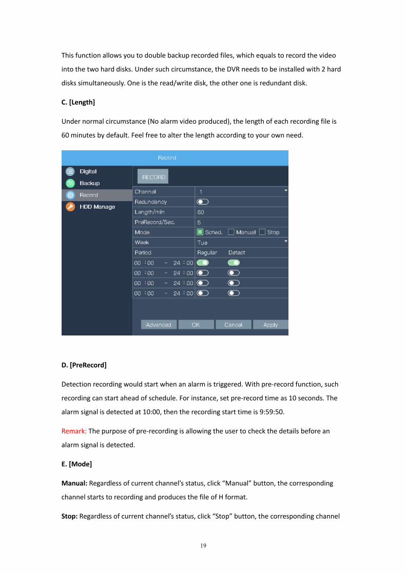
C. [Length]
Under normal circumstance (No alarm video produced), the length of each recording file is
60 minutes by default. Feel free to alter the length according to your own need.
D. [PreRecord]
Detection recording would start when an alarm is triggered. With pre-record function, such
recording can start ahead of schedule. For instance, set pre-record time as 10 seconds. The
alarm signal is detected at 10:00, then the recording start time is 9:59:50.
Remark: The purpose of pre-recording is allowing the user to check the details before an
alarm signal is detected.
E. [Mode]
Manual: Regardless of current channel’s status, click “Manual” button, the corresponding
channel starts to recording and produces the file of H format.
Stop: Regardless of current channel’s status, click “Stop” button, the corresponding channel
20
ceases to record.
Schedule: Schedule record mode and time to produce corresponding video footage.
There are two record modes: Regular, Detect.
Regular: In the set time period, the DVR produces the regular recording. The recording
file format is “R”.
Detect: Within the set time period, if triggered “Motion Detection”, “Video Blind”, or
“Video Loss” alarm, and the corresponding alarm function is turned on, then the DVR
would produce the recording file of format “M”.
F. [Week]
Choose Monday, Tuesday, Wednesday, Thursday, Friday, Saturday, Sunday or All.
G. [ Period]
ELEC DVR only records during the set time period. You can set multiple time periods up to 4.
The time period can be intermittent, consecutive and repeated.
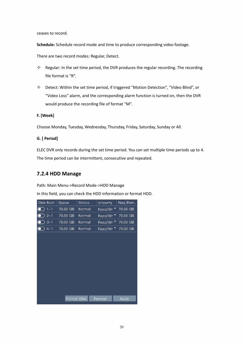
7.2.4 HDD Manage
Path: Main Menu->Record Mode->HDD Manage
In this field, you can check the HDD information or format HDD.
21
HDD Information: You can check “Space, Status, Property, Req./Rem”.
Format HDD: If the HDD memory is full, format HDD could make it re-utilized.
Remark:
1. A DVR without a hard drive can only provide you with viewing, but not recording or
playback.
2. If the model you ordered doesn’t include a hard disk drive, please refer to the
recommended purchase information:
Recommended HDD Size: 2.5 Inches
Recommended module numbers:
●Western Digital Surveillance
WD AV-25 series WD5000BUDT 500GB, WD10EURX 1TB
● HGST Surveillance Series
HCC545050A7E630 500GB, HCC541010A9E630 1TB
Then install the HDD in accordance with the instructions below.
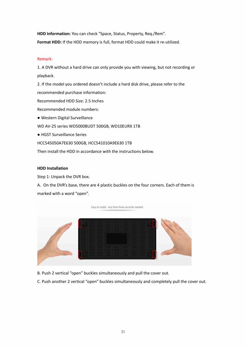
HDD Installation
Step 1: Unpack the DVR box.
A. On the DVR’s base, there are 4 plastic buckles on the four corners. Each of them is
marked with a word “open”.
B. Push 2 vertical “open” buckles simultaneously and pull the cover out.
C. Push another 2 vertical “open” buckles simultaneously and completely pull the cover out.

22
Step 2: There are two cables linked to DVR mother board. The one with a smaller interface is
the SATA cable, the one with a bigger interface is the power cord. Hook up these two cables
to corresponding hard drive’s interface.
Step 3: Put HDD inside the DVR and keep it in a fixed position.
Step 4: Replace the DVR cover.
Remark: Skip this part if the HDD is pre-installed.
7.3 System Info (the upside down exclamation mark of “!”)
Path: Main Menu->the upside down exclamation mark of “!”
23
7.3.1 HDD Info
Path: Main Menu->the upside down exclamation mark of “!”->HDD Info
Display all the related information of HDD.
7.3.2 LOG
Path: Main Menu->the upside down exclamation mark of “!”->LOG
Display system events like Login, Logout, Shutdown. You can also remove all logs by clicking
“Remove”.
7.3.3 Version
Path: Main Menu->the upside down exclamation mark of “!”->Version
Check Lynkn ID, Nat status, and other related system info.
7.3.4 Online User
Path: Main Menu->the upside down exclamation mark of “!”->Online User
Display the information about the online user like User Name, IP, Login Type.
7.4 Startup Wizard
Refer to Chapter 4.
7.5 Alarm Setting
Path: Main Menu->Alarm Setting
24
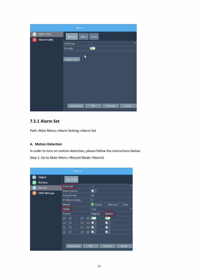
7.5.1 Alarm Set
Path: Main Menu->Alarm Setting->Alarm Set
A. Motion Detection
In order to turn on motion detection, please follow the instructions below:
Step 1: Go to Main Menu->Record Mode->Record.
25
Step 2: Set the relevant information.
Channel: Select All; Week: Select All; Turn off Regular, open Detect; Then click OK.
Step 3: Go to Main Menu->Alarm Setting->Alarm Set.
Step 4: Click “Motion”. Select “All” channel, Toggle on “Enable”, then click “Advanced”.
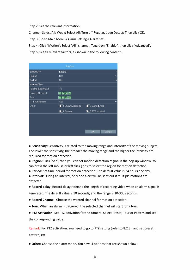
Step 5: Set all relevant factors, as shown in the following content.
● Sensitivity: Sensitivity is related to the moving range and intensity of the moving subject.The lower the sensitivity, the broader the moving range and the higher the intensity arerequired for motion detection.● Region: Click “Set”, then you can set motion detection region in the pop-up window. Youcan press the left mouse or left click grids to select the region for motion detection.● Period: Set time period for motion detection. The default value is 24 hours one day.● Interval: During an interval, only one alert will be sent out if multiple motions aredetected.
● Record delay: Record delay refers to the length of recording video when an alarm signal is
generated. The default value is 10 seconds, and the range is 10-300 seconds.
● Record Channel: Choose the wanted channel for motion detection.
● Tour: When an alarm is triggered, the selected channel will start for a tour.
● PTZ Activation: Set PTZ activation for the camera. Select Preset, Tour or Pattern and set
the corresponding value.
Remark: For PTZ activation, you need to go to PTZ setting (refer to 8.2.3), and set preset,
pattern, etc.
● Other: Choose the alarm mode. You have 4 options that are shown below:
26
A. Show messages: A red icon of little bouncing person will appear on the relevant channel
when motion is detected.
B. Send Email: Send email alerts to assigned email address.
C. Buzzer: Certain of our DVR models can produce buzz when motion is detected.
D. FTP upload: Upload alarm video to FTP server.
Step 6: Click “OK” on the motion interface and “OK” on the alarm set interface.
B. Blind Detection
Steps are the same as Motion Detection.
C. Loss Detection
Steps are the same as Motion Detection.
7.5.2 Abnormality
Path: Main Menu->Alarm Setting->Abnormality
When enabled, you will receive an alert once an abnormality detected. Such abnormalities
are No Disk, Disk Error, Disk No Space, Net Disconnection, IP conflict.
“ShowMessages” and “Buzzer” are the alarm options for abnormality.
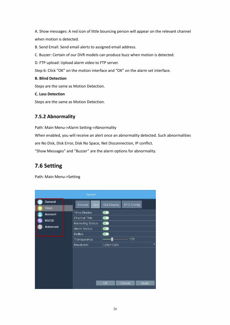
7.6 Setting
Path: Main Menu->Setting
27
7.6.1 General
Path: Main Menu->Setting->General
You can view or edit general settings. The operations in this field include:
System Time: View or correct system time.
DST: Set DST.
Date Format: Set date format as YYYY MM DD, MM DD YYYY, or DD MM YYYY.
Language: English or Chinese.
Video Standard: PLA or NTSC.
Startup Wizard: Enable or disable.
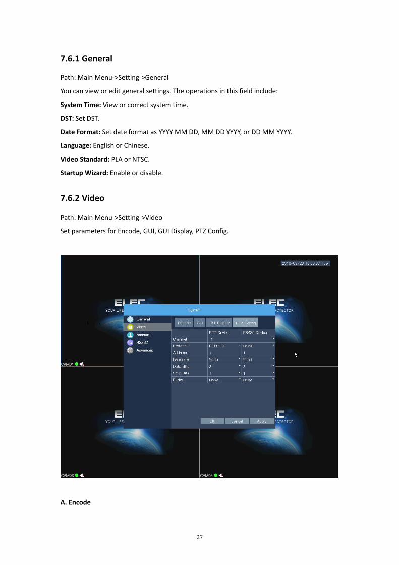
7.6.2 Video
Path: Main Menu->Setting->Video
Set parameters for Encode, GUI, GUI Display, PTZ Config.
A. Encode
28
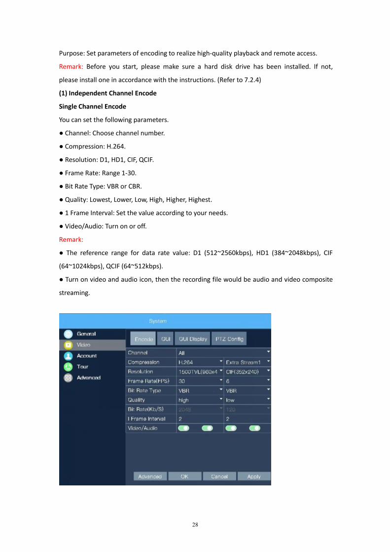
Purpose: Set parameters of encoding to realize high-quality playback and remote access.
Remark: Before you start, please make sure a hard disk drive has been installed. If not,
please install one in accordance with the instructions. (Refer to 7.2.4)
(1) Independent Channel Encode
Single Channel Encode
You can set the following parameters.
● Channel: Choose channel number.
● Compression: H.264.
● Resolution: D1, HD1, CIF, QCIF.
● Frame Rate: Range 1-30.
● Bit Rate Type: VBR or CBR.
● Quality: Lowest, Lower, Low, High, Higher, Highest.
● 1 Frame Interval: Set the value according to your needs.
● Video/Audio: Turn on or off.
Remark:
● The reference range for data rate value: D1 (512~2560kbps), HD1 (384~2048kbps), CIF
(64~1024kbps), QCIF (64~512kbps).
● Turn on video and audio icon, then the recording file would be audio and video composite
streaming.
29
Copy and paste channel encode
Step 1: Choose Channel 1, set the parameters. (Refer to Single Channel Encode)
Step 2: Click “Advanced”, then click “Copy”. Choose channel 2, then click “OK”.
Step 3: Set other channels using the same method.
(2) Extra Stream Set
Applicable to client-end and mobile phone monitoring.
Step 1: Choose the channel for extra stream set.
Step 2: Configure the related parameter. (Refer to Single Channel Encode)
B. GUI
Enable or disable “Time Display”, “Channel Title”, “Recording Status”, “Alarm Status”,
“Deflick” according to your own habit. Also, you can adjust transparency and resolution in
the same time. Remember to click “OK” after the setting.
C. GUI Display
You can view or edit channel title. Enable or disable time display, channel title, region cover.
After the set, click "OK" to save the settings.
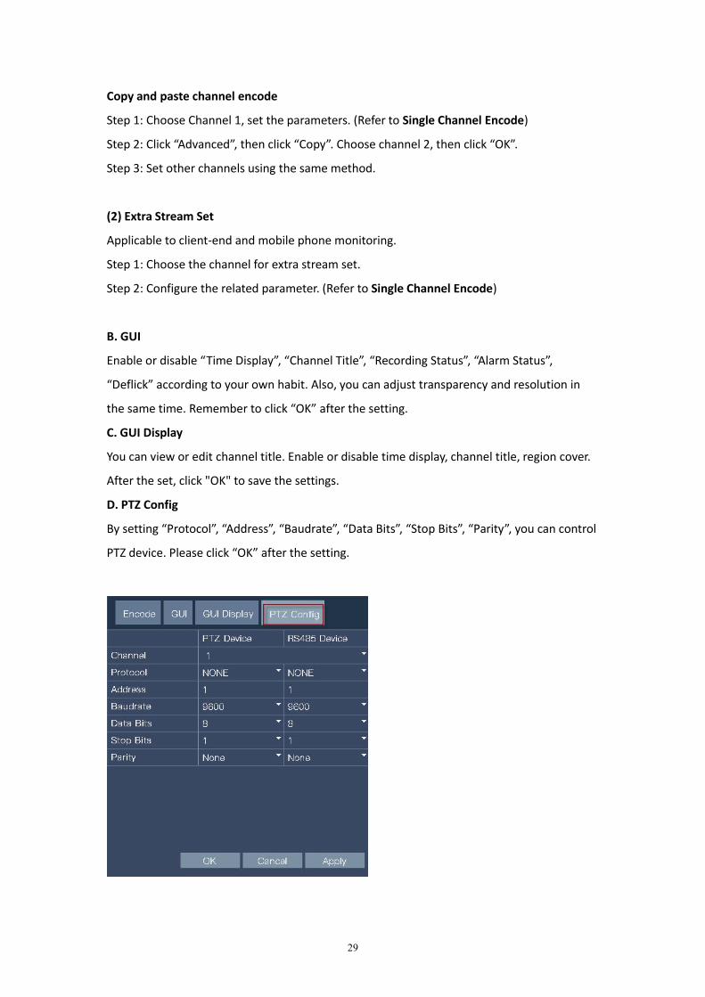
D. PTZ Config
By setting “Protocol”, “Address”, “Baudrate”, “Data Bits”, “Stop Bits”, “Parity”, you can control
PTZ device. Please click “OK” after the setting.
30
7.6.3 Account
Path: Main Menu->Setting->Account
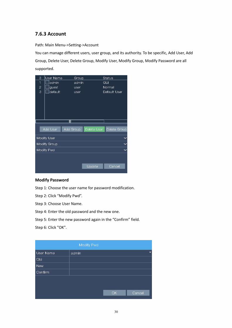
You can manage different users, user group, and its authority. To be specific, Add User, Add
Group, Delete User, Delete Group, Modify User, Modify Group, Modify Password are all
supported.
Modify Password
Step 1: Choose the user name for password modification.
Step 2: Click “Modify Pwd”.
Step 3: Choose User Name.
Step 4: Enter the old password and the new one.
Step 5: Enter the new password again in the “Confirm” field.
Step 6: Click "OK".
31
7.6.4 RS232
Path: Main Menu->Setting->RS232
The RS232 serial port is used for debugging and upgrading. You can view or edit the setting
for Parity, Data Bits. Stop Bits, etc in this field.
7.6.5 Advanced
Path: Main Menu->Setting->Advanced
View or edit the settings for AutoMaintain, Import/Export, Restore, Upgrade.
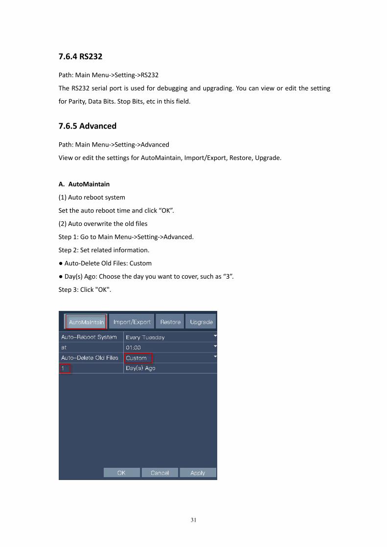
A. AutoMaintain
(1) Auto reboot system
Set the auto reboot time and click “OK”.
(2) Auto overwrite the old files
Step 1: Go to Main Menu->Setting->Advanced.
Step 2: Set related information.
● Auto-Delete Old Files: Custom
● Day(s) Ago: Choose the day you want to cover, such as “3”.
Step 3: Click "OK".
32
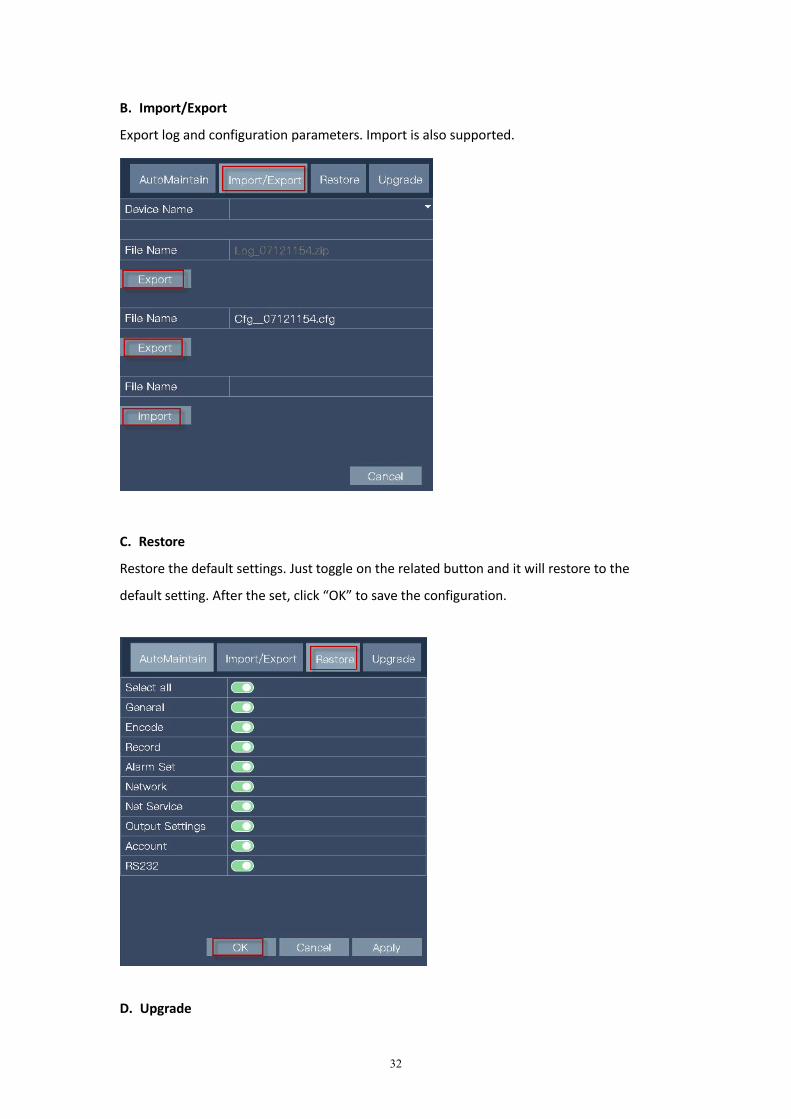
B. Import/Export
Export log and configuration parameters. Import is also supported.
C. Restore
Restore the default settings. Just toggle on the related button and it will restore to the
default setting. After the set, click “OK” to save the configuration.
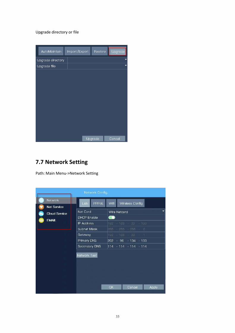
D. Upgrade
33
Upgrade directory or file
7.7 Network Setting
Path: Main Menu->Network Setting
34
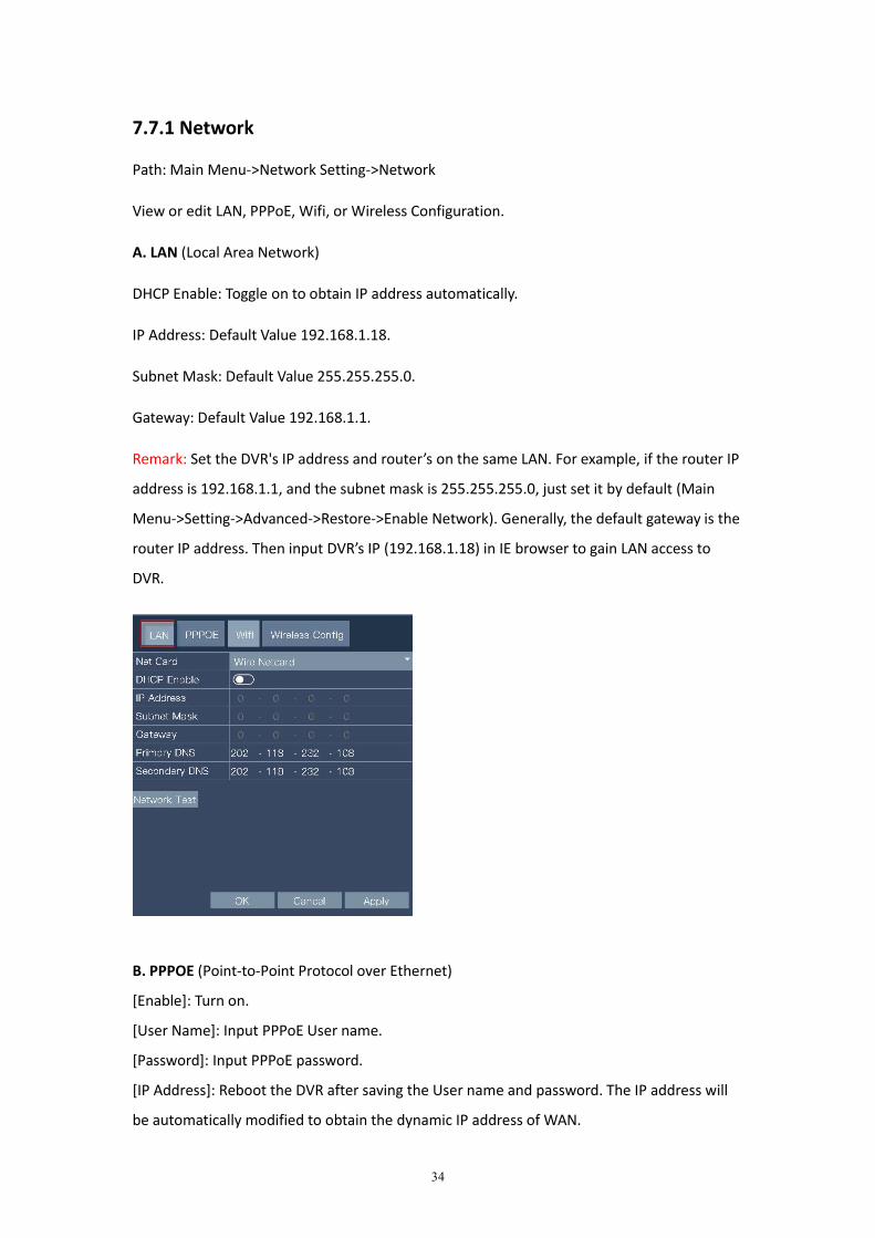
7.7.1 Network
Path: Main Menu->Network Setting->Network
View or edit LAN, PPPoE, Wifi, or Wireless Configuration.
A. LAN (Local Area Network)
DHCP Enable: Toggle on to obtain IP address automatically.
IP Address: Default Value 192.168.1.18.
Subnet Mask: Default Value 255.255.255.0.
Gateway: Default Value 192.168.1.1.
Remark: Set the DVR's IP address and router’s on the same LAN. For example, if the router IP
address is 192.168.1.1, and the subnet mask is 255.255.255.0, just set it by default (Main
Menu->Setting->Advanced->Restore->Enable Network). Generally, the default gateway is the
router IP address. Then input DVR’s IP (192.168.1.18) in IE browser to gain LAN access to
DVR.
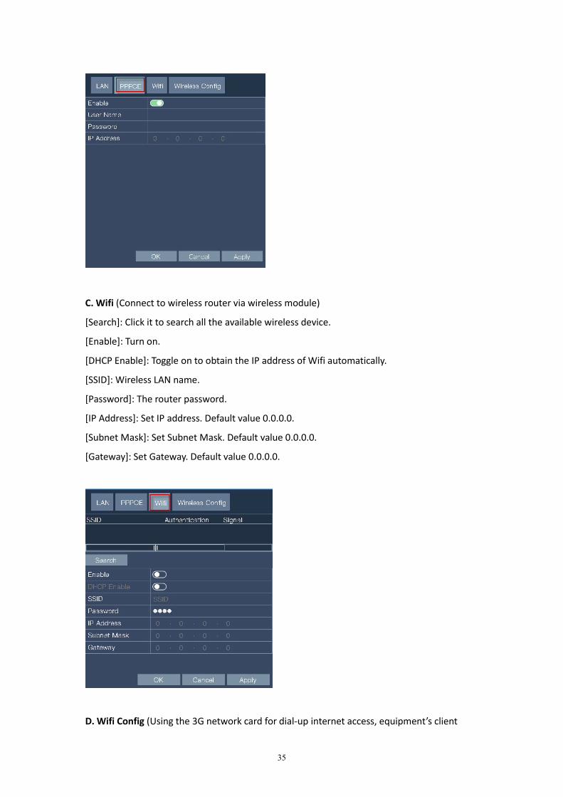
B. PPPOE (Point-to-Point Protocol over Ethernet)
[Enable]: Turn on.
[User Name]: Input PPPoE User name.
[Password]: Input PPPoE password.
[IP Address]: Reboot the DVR after saving the User name and password. The IP address will
be automatically modified to obtain the dynamic IP address of WAN.
35
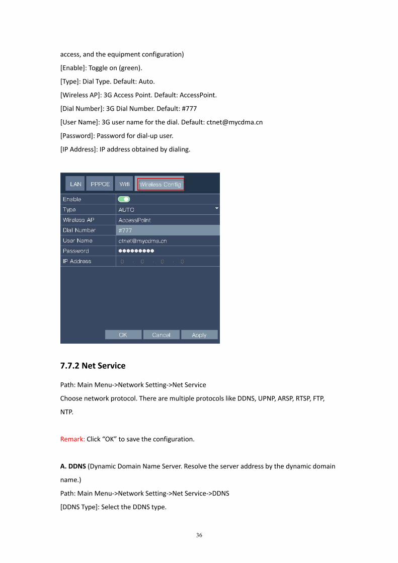
C. Wifi (Connect to wireless router via wireless module)
[Search]: Click it to search all the available wireless device.
[Enable]: Turn on.
[DHCP Enable]: Toggle on to obtain the IP address of Wifi automatically.
[SSID]: Wireless LAN name.
[Password]: The router password.
[IP Address]: Set IP address. Default value 0.0.0.0.
[Subnet Mask]: Set Subnet Mask. Default value 0.0.0.0.
[Gateway]: Set Gateway. Default value 0.0.0.0.
D. Wifi Config (Using the 3G network card for dial-up internet access, equipment’s client
36
access, and the equipment configuration)
[Enable]: Toggle on (green).
[Type]: Dial Type. Default: Auto.
[Wireless AP]: 3G Access Point. Default: AccessPoint.
[Dial Number]: 3G Dial Number. Default: #777
[User Name]: 3G user name for the dial. Default: [email protected]
[Password]: Password for dial-up user.
[IP Address]: IP address obtained by dialing.
7.7.2 Net Service
Path: Main Menu->Network Setting->Net Service
Choose network protocol. There are multiple protocols like DDNS, UPNP, ARSP, RTSP, FTP,
NTP.
Remark: Click “OK” to save the configuration.
A. DDNS (Dynamic Domain Name Server. Resolve the server address by the dynamic domain
name.)
Path: Main Menu->Network Setting->Net Service->DDNS
[DDNS Type]: Select the DDNS type.
37
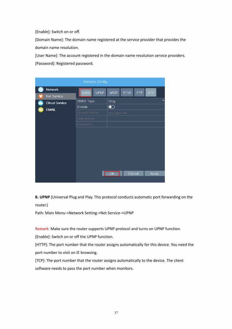
[Enable]: Switch on or off.
[Domain Name]: The domain name registered at the service provider that provides the
domain name resolution.
[User Name]: The account registered in the domain name resolution service providers.
[Password]: Registered password.
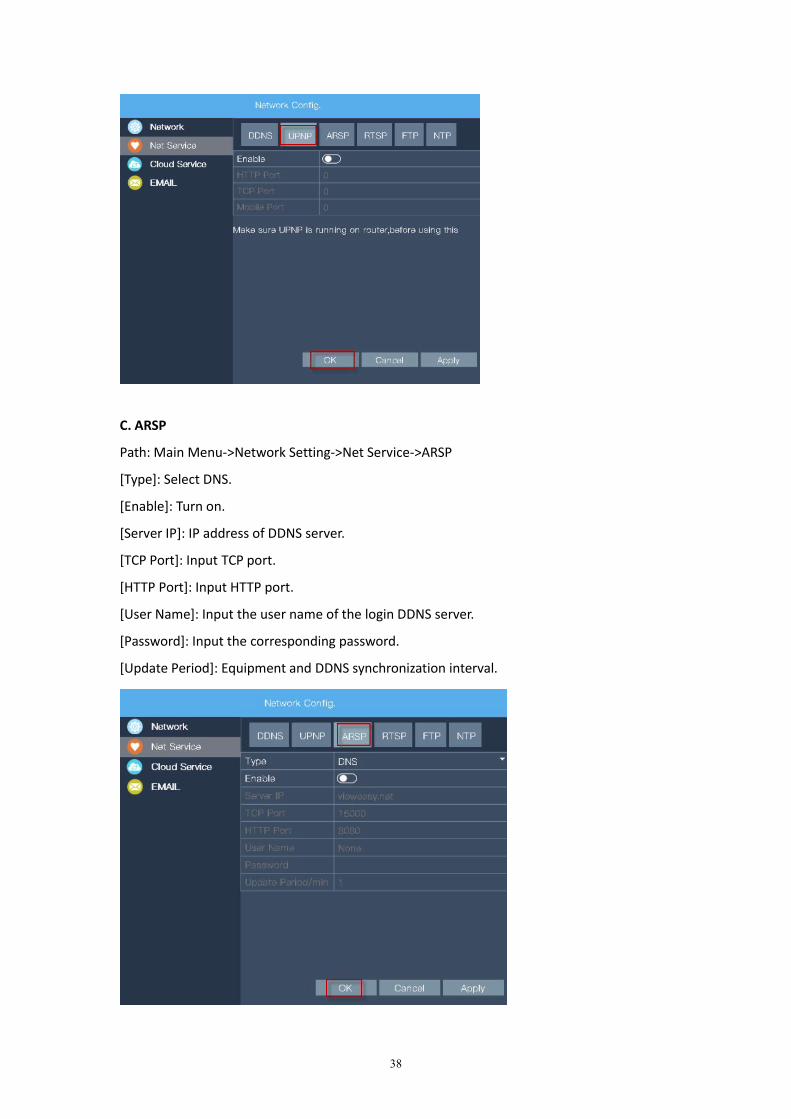
B. UPNP (Universal Plug and Play. This protocol conducts automatic port forwarding on the
router.)
Path: Main Menu->Network Setting->Net Service->UPNP
Remark: Make sure the router supports UPNP protocol and turns on UPNP function.
[Enable]: Switch on or off the UPNP function.
[HTTP]: The port number that the router assigns automatically for this device. You need the
port number to visit on IE browsing.
[TCP]: The port number that the router assigns automatically to the device. The client
software needs to pass the port number when monitors.
38
C. ARSP
Path: Main Menu->Network Setting->Net Service->ARSP
[Type]: Select DNS.
[Enable]: Turn on.
[Server IP]: IP address of DDNS server.
[TCP Port]: Input TCP port.
[HTTP Port]: Input HTTP port.
[User Name]: Input the user name of the login DDNS server.
[Password]: Input the corresponding password.
[Update Period]: Equipment and DDNS synchronization interval.
39
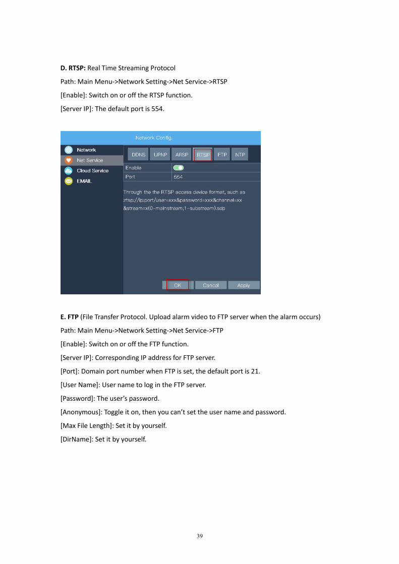
D. RTSP: Real Time Streaming Protocol
Path: Main Menu->Network Setting->Net Service->RTSP
[Enable]: Switch on or off the RTSP function.
[Server IP]: The default port is 554.
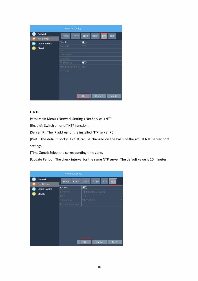
E. FTP (File Transfer Protocol. Upload alarm video to FTP server when the alarm occurs)
Path: Main Menu->Network Setting->Net Service->FTP
[Enable]: Switch on or off the FTP function.
[Server IP]: Corresponding IP address for FTP server.
[Port]: Domain port number when FTP is set, the default port is 21.
[User Name]: User name to log in the FTP server.
[Password]: The user’s password.
[Anonymous]: Toggle it on, then you can’t set the user name and password.
[Max File Length]: Set it by yourself.
[DirName]: Set it by yourself.
40
F. NTP
Path: Main Menu->Network Setting->Net Service->NTP
[Enable]: Switch on or off NTP function.
[Server IP]: The IP address of the installed NTP server PC.
[Port]: The default port is 123. It can be changed on the basis of the actual NTP server port
settings.
[Time Zone]: Select the corresponding time zone.
[Update Period]: The check interval for the same NTP server. The default value is 10 minutes.

41
7.7.3 Cloud Service
Path: Main Menu->Network Setting->Cloud Service
Cloud service must be enabled in order to remotely view on a mobile device. Device ID can
also be found in this field.
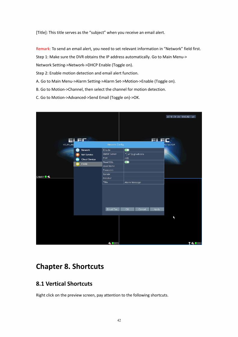
7.7.4 EMAIL
Path: Main Menu->Network Setting->EMAIL
[Enable]: Switch on or off “Enable”.
[SMTP server]: SMTP server address for your email service provider.
[Port]: Port number used by your email service provider for SMTP.
[Need SSL]: Toggle the “Need SSL” to green to enable it.
[User Name]: Your email address.
[Password]: Your email password.
[Sender]: Input the sender’s name you desire, e.g. Mr.Jones.
[Receiver]: The email address to receive the email alert. You can also use the same email
address as the one in “User Name”.
42
[Title]: This title serves as the “subject” when you receive an email alert.
Remark: To send an email alert, you need to set relevant information in “Network” field first.
Step 1: Make sure the DVR obtains the IP address automatically. Go to Main Menu->
Network Setting->Network->DHCP Enable (Toggle on).
Step 2: Enable motion detection and email alert function.
A. Go to Main Menu->Alarm Setting->Alarm Set->Motion->Enable (Toggle on).
B. Go to Motion->Channel, then select the channel for motion detection.
C. Go to Motion->Advanced->Send Email (Toggle on)->OK.
Chapter 8. Shortcuts
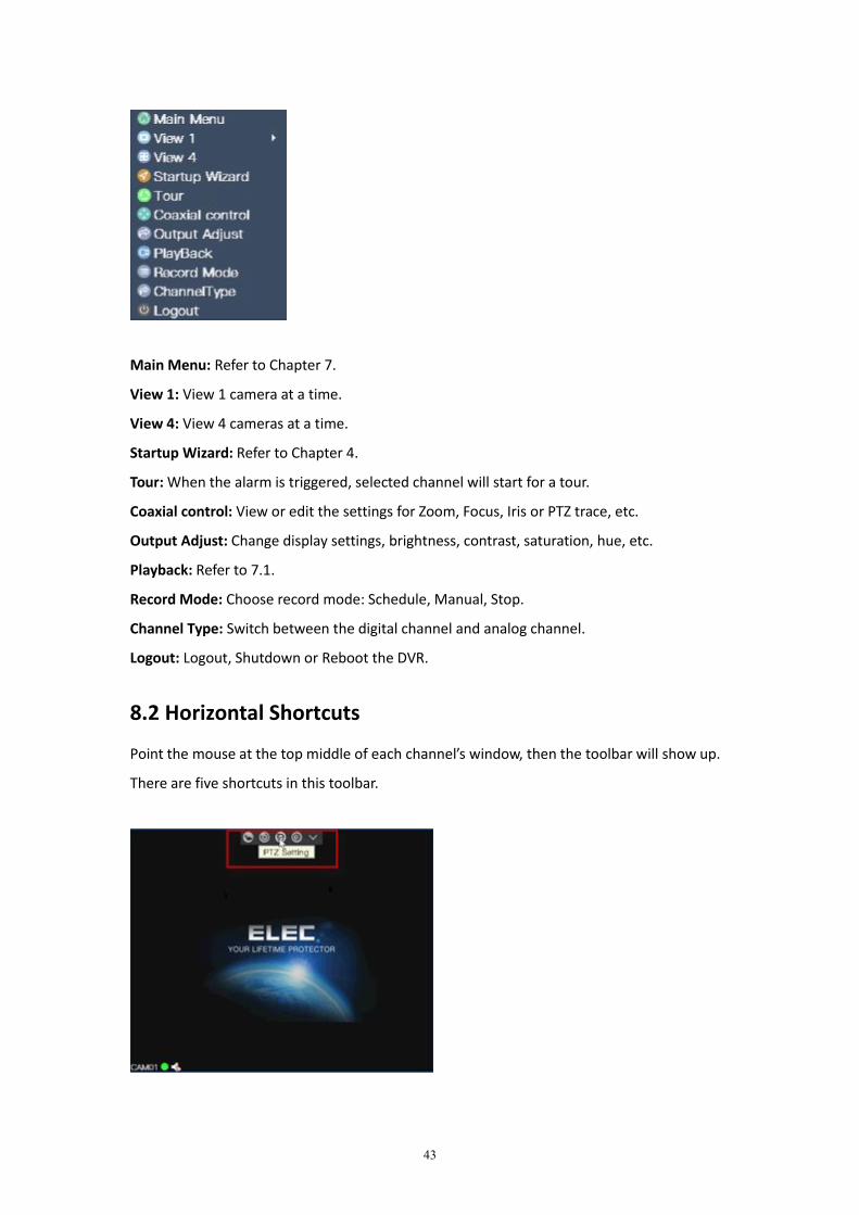
8.1 Vertical Shortcuts
Right click on the preview screen, pay attention to the following shortcuts.
43
Main Menu: Refer to Chapter 7.
View 1: View 1 camera at a time.
View 4: View 4 cameras at a time.
Startup Wizard: Refer to Chapter 4.
Tour: When the alarm is triggered, selected channel will start for a tour.
Coaxial control: View or edit the settings for Zoom, Focus, Iris or PTZ trace, etc.
Output Adjust: Change display settings, brightness, contrast, saturation, hue, etc.
Playback: Refer to 7.1.
Record Mode: Choose record mode: Schedule, Manual, Stop.
Channel Type: Switch between the digital channel and analog channel.
Logout: Logout, Shutdown or Reboot the DVR.
8.2 Horizontal Shortcuts
Point the mouse at the top middle of each channel’s window, then the toolbar will show up.
There are five shortcuts in this toolbar.
44
8.2.1 Close Record
Click it, the DVR would stop recording.
8.2.2 Playback
Refer to 7.1.
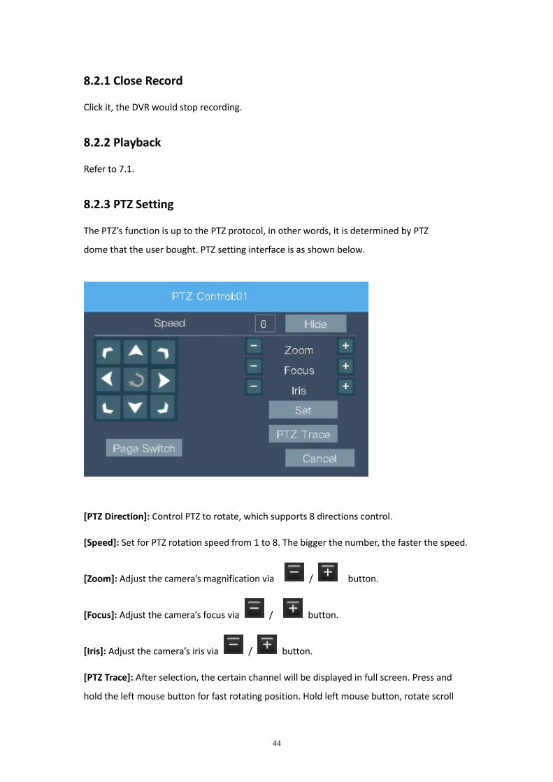
8.2.3 PTZ Setting
The PTZ’s function is up to the PTZ protocol, in other words, it is determined by PTZ
dome that the user bought. PTZ setting interface is as shown below.
[PTZ Direction]: Control PTZ to rotate, which supports 8 directions control.
[Speed]: Set for PTZ rotation speed from 1 to 8. The bigger the number, the faster the speed.
[Zoom]: Adjust the camera’s magnification via / button.
[Focus]: Adjust the camera’s focus via / button.
[Iris]: Adjust the camera’s iris via / button.
[PTZ Trace]: After selection, the certain channel will be displayed in full screen. Press and
hold the left mouse button for fast rotating position. Hold left mouse button, rotate scroll
45
wheel to adjust camera’s magnification.
[Set]: Enter into “PTZ Config” menu.
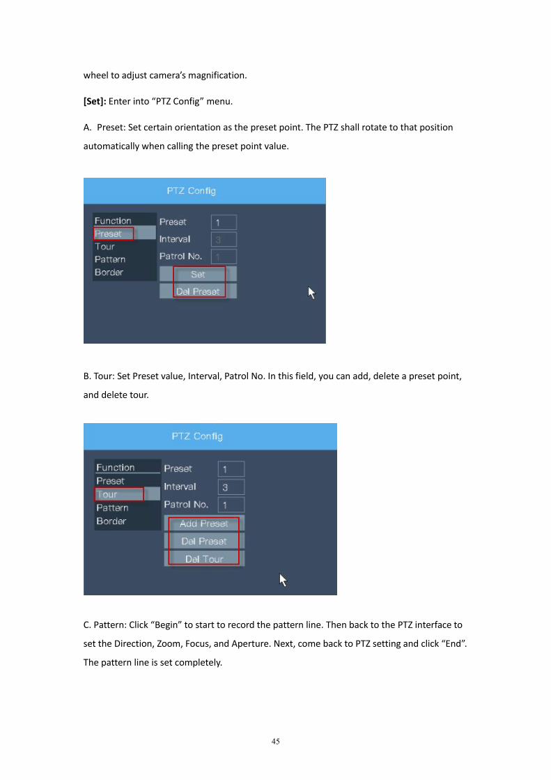
A. Preset: Set certain orientation as the preset point. The PTZ shall rotate to that position
automatically when calling the preset point value.
B. Tour: Set Preset value, Interval, Patrol No. In this field, you can add, delete a preset point,
and delete tour.
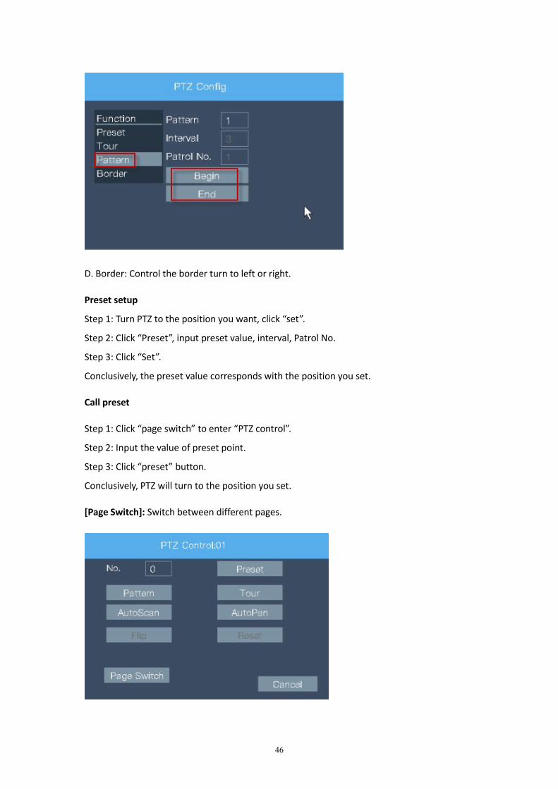
C. Pattern: Click “Begin” to start to record the pattern line. Then back to the PTZ interface to
set the Direction, Zoom, Focus, and Aperture. Next, come back to PTZ setting and click “End”.
The pattern line is set completely.
46
D. Border: Control the border turn to left or right.
Preset setup
Step 1: Turn PTZ to the position you want, click “set”.
Step 2: Click “Preset”, input preset value, interval, Patrol No.
Step 3: Click “Set”.
Conclusively, the preset value corresponds with the position you set.
Call preset
Step 1: Click “page switch” to enter “PTZ control”.
Step 2: Input the value of preset point.
Step 3: Click “preset” button.
Conclusively, PTZ will turn to the position you set.
[Page Switch]: Switch between different pages.
47
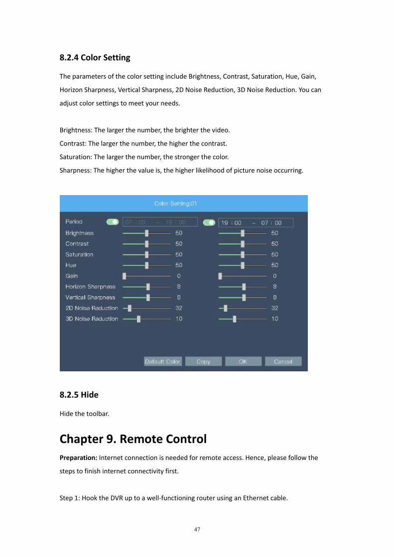
8.2.4 Color Setting
The parameters of the color setting include Brightness, Contrast, Saturation, Hue, Gain,
Horizon Sharpness, Vertical Sharpness, 2D Noise Reduction, 3D Noise Reduction. You can
adjust color settings to meet your needs.
Brightness: The larger the number, the brighter the video.
Contrast: The larger the number, the higher the contrast.
Saturation: The larger the number, the stronger the color.
Sharpness: The higher the value is, the higher likelihood of picture noise occurring.
8.2.5 Hide
Hide the toolbar.
Chapter 9. Remote ControlPreparation: Internet connection is needed for remote access. Hence, please follow the
steps to finish internet connectivity first.
Step 1: Hook the DVR up to a well-functioning router using an Ethernet cable.
48
Step 2: Turn on Cloud Service. (Main Menu->Network Setting->Cloud Service->
Enable (toggle on)->OK).
Step 3: Turn on "DHCP Enable" (green). (Main Menu->Network Setting->Network->
Toggle on "DHCP Enable"->OK).
Step 4: Reboot DVR system (Right click on the preview interface->Logout->Reboot). Re-login
to your DVR after reboot with user name and password.
Step 5: Make sure Nat status reads connected. (Main Menu->System Info (the upside down
exclamation mark of “!”)->Version->Nat Status).
Then follow the steps below to gain remote access easily.
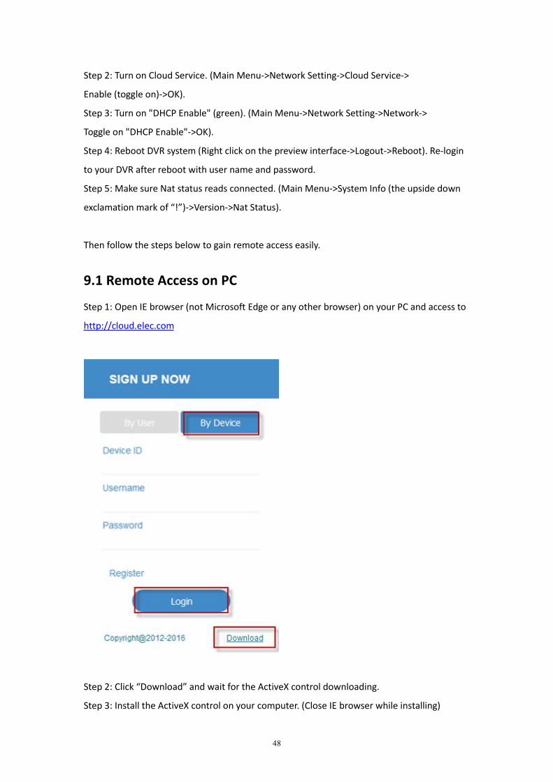
9.1 Remote Access on PC
Step 1: Open IE browser (not Microsoft Edge or any other browser) on your PC and access to
http://cloud.elec.com
Step 2: Click “Download” and wait for the ActiveX control downloading.
Step 3: Install the ActiveX control on your computer. (Close IE browser while installing)
49
Step 4: After the installation, re-open IE browser and access to http://cloud.elec.com
Step 5: Retrieve Device ID.
Right click on the DVR’s initial interface.
Go to Main Menu->System Info (the upside down exclamation mark of “!”)->Version
->Lynkn ID (Also serves as Device ID).
Step 6: Login
On the main interface of cloud monitoring, click “By Device”. Input Device ID (Lynkn ID),
Username (admin by default), Password (leave it empty). Then click “Login”.
Step 7: Click “Play” button in the left column for each camera, then you can remotely view
the video on PC.
Note: Remotely view on PC is only supported for Internet Explorer 7 or above version.
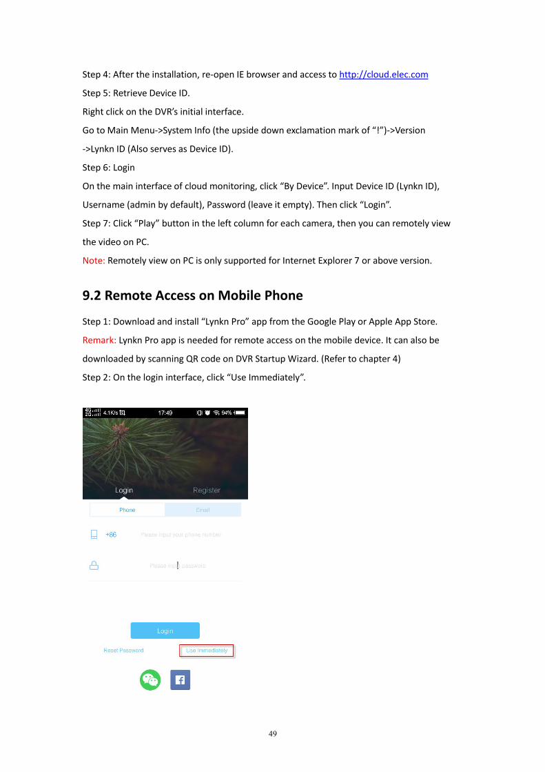
9.2 Remote Access on Mobile Phone
Step 1: Download and install “Lynkn Pro” app from the Google Play or Apple App Store.
Remark: Lynkn Pro app is needed for remote access on the mobile device. It can also be
downloaded by scanning QR code on DVR Startup Wizard. (Refer to chapter 4)
Step 2: On the login interface, click “Use Immediately”.
50
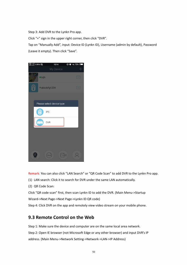
Step 3: Add DVR to the Lynkn Pro app.
Click “+” sign in the upper right corner, then click “DVR”.
Tap on “Manually Add”, input: Device ID (Lynkn ID), Username (admin by default), Password
(Leave it empty). Then click “Save”.
Remark: You can also click “LAN Search” or “QR Code Scan” to add DVR to the Lynkn Pro app.
(1) LAN search: Click it to search for DVR under the same LAN automatically.
(2) QR Code Scan:
Click “QR code scan” first, then scan Lynkn ID to add the DVR. (Main Menu->Startup
Wizard->Next Page->Next Page->Lynkn ID QR code)
Step 4: Click DVR on the app and remotely view video stream on your mobile phone.
9.3 Remote Control on the Web
Step 1: Make sure the device and computer are on the same local area network.
Step 2: Open IE browser (not Microsoft Edge or any other browser) and input DVR’s IP
address. (Main Menu->Network Setting->Network->LAN->IP Address)
51
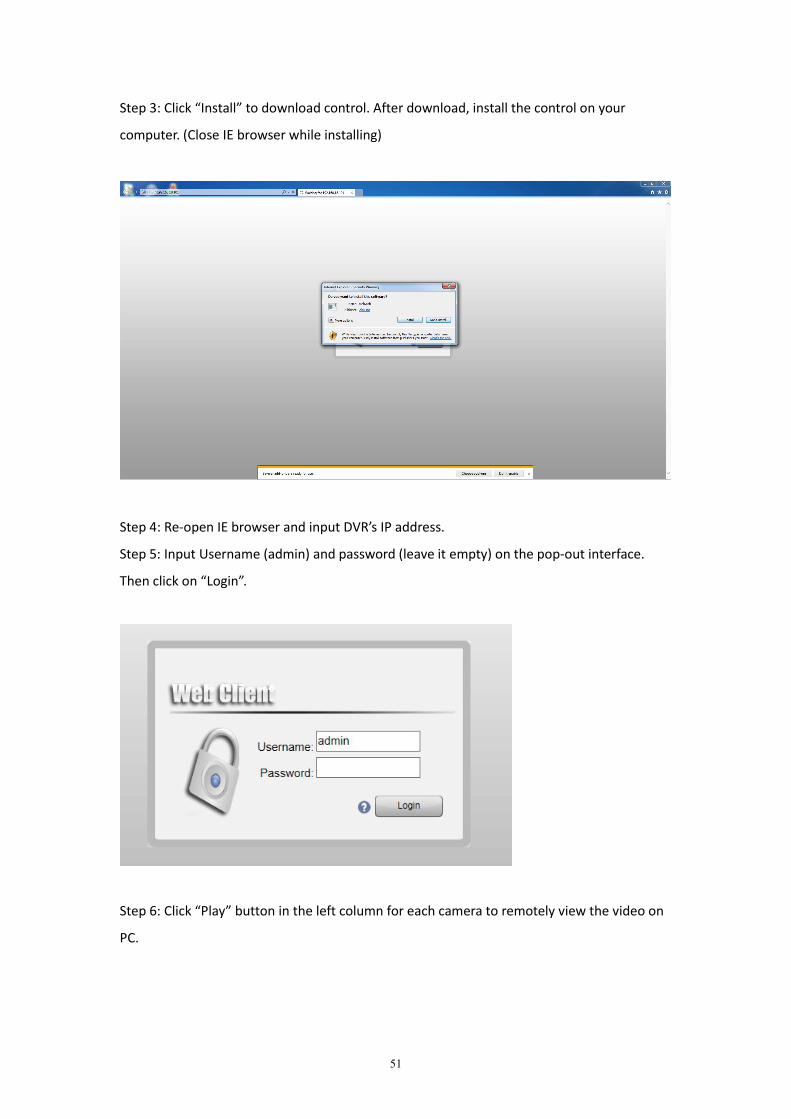
Step 3: Click “Install” to download control. After download, install the control on your
computer. (Close IE browser while installing)
Step 4: Re-open IE browser and input DVR’s IP address.
Step 5: Input Username (admin) and password (leave it empty) on the pop-out interface.
Then click on “Login”.
Step 6: Click “Play” button in the left column for each camera to remotely view the video on
PC.
52
9.4 Remote Control on CMS
Remark: Be informed the CMS software is optimized for LAN (Local Area Network) access.
Step 1: Make sure the device and computer are on the same local area network.
Step 2: Download CMS software and launch it on your computer. Download link:
https://www.dropbox.com/s/h8vct74q246oyjd/English%20version%20CMS.rar?dl=0
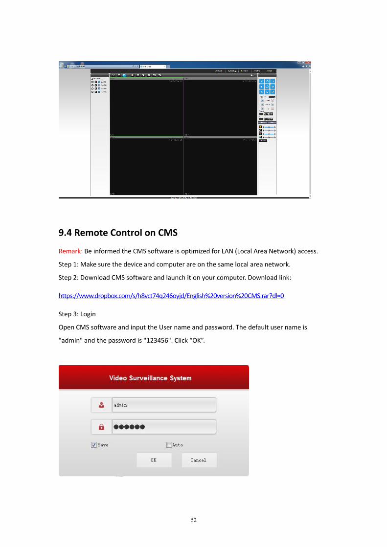
Step 3: Login
Open CMS software and input the User name and password. The default user name is
"admin" and the password is "123456". Click “OK”.
53
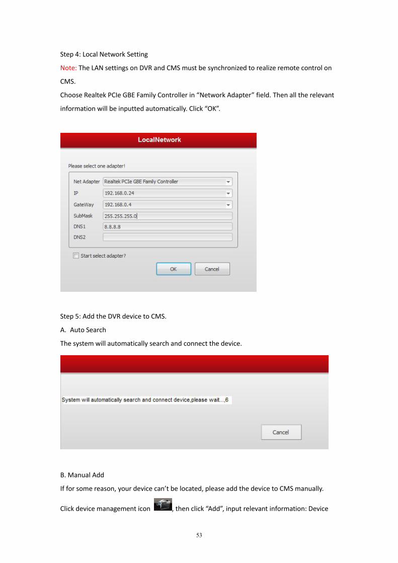
Step 4: Local Network Setting
Note: The LAN settings on DVR and CMS must be synchronized to realize remote control on
CMS.
Choose Realtek PCIe GBE Family Controller in “Network Adapter” field. Then all the relevant
information will be inputted automatically. Click “OK”.
Step 5: Add the DVR device to CMS.
A. Auto Search
The system will automatically search and connect the device.
B. Manual Add
If for some reason, your device can’t be located, please add the device to CMS manually.
Click device management icon , then click “Add”, input relevant information: Device
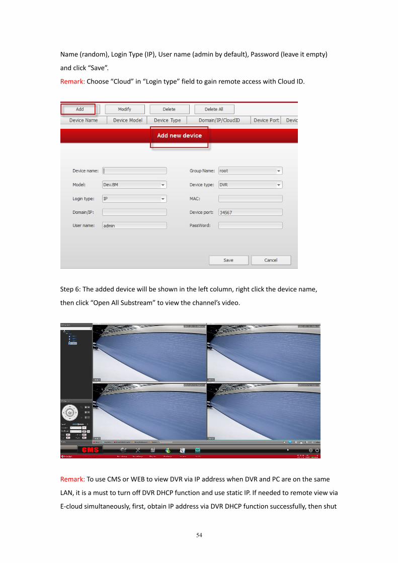
54
Name (random), Login Type (IP), User name (admin by default), Password (leave it empty)
and click “Save”.
Remark: Choose “Cloud” in “Login type” field to gain remote access with Cloud ID.
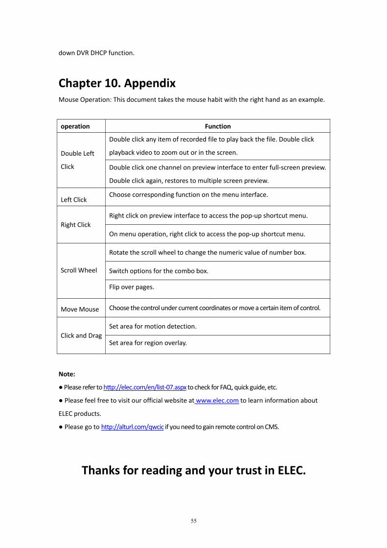
Step 6: The added device will be shown in the left column, right click the device name,
then click “Open All Substream” to view the channel’s video.
Remark: To use CMS or WEB to view DVR via IP address when DVR and PC are on the same
LAN, it is a must to turn off DVR DHCP function and use static IP. If needed to remote view via
E-cloud simultaneously, first, obtain IP address via DVR DHCP function successfully, then shut
55
down DVR DHCP function.
Chapter 10. AppendixMouse Operation: This document takes the mouse habit with the right hand as an example.
operation Function
Double Left
Click
Double click any item of recorded file to play back the file. Double click
playback video to zoom out or in the screen.
Double click one channel on preview interface to enter full-screen preview.
Double click again, restores to multiple screen preview.
Left ClickChoose corresponding function on the menu interface.
Right ClickRight click on preview interface to access the pop-up shortcut menu.
On menu operation, right click to access the pop-up shortcut menu.
Scroll Wheel
Rotate the scroll wheel to change the numeric value of number box.
Switch options for the combo box.
Flip over pages.
Move Mouse Choose thecontrol under current coordinatesormovea certain itemof control.
Click and DragSet area for motion detection.
Set area for region overlay.
Note:
●Please refer to http://elec.com/en/list-07.aspx to check for FAQ, quick guide, etc.
● Please feel free to visit our official website at www.elec.com to learn information about
ELEC products.
● Please go to http://alturl.com/qwcic if youneedtogain remote control onCMS.
Thanks for reading and your trust in ELEC.