
ELEC 6270 Low power design of Electronic Circuits Advisor: Dr.Vishwani Agrawal Student: Chaitanya...
25
ELEC 6270 Low power design of Electronic Circuits Advisor: Dr.Vishwani Agrawal Student: Chaitanya Bandi
-
Upload
mariah-grant -
Category
Documents
-
view
218 -
download
0
Transcript of ELEC 6270 Low power design of Electronic Circuits Advisor: Dr.Vishwani Agrawal Student: Chaitanya...

ELEC 6270 Low power design of Electronic Circuits
Advisor: Dr.Vishwani AgrawalStudent: Chaitanya Bandi
IndexRing Oscillator OperationTools UsedSchematicPower and Frequency Versus Voltage
(Expected and Observed) for different values of N (where N is the number of gates).
References
Ring OscillatorA ring oscillator is a device composed of an
odd number of NOT gates whose output oscillates between two voltage levels,
representing 1 and 0.
The NOT gates, or inverters, are attached in a chain; the output of the last inverter is fed back into the first
Tools UsedDesign Architect: To create and Edit the
Schematic
Eldo: To find the Frequency of oscillations and Average Power consumed
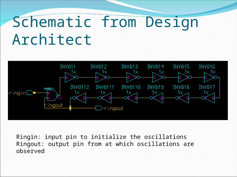
Schematic from Design Architect
Ringin: input pin to initialize the oscillationsRingout: output pin from at which oscillations are observed
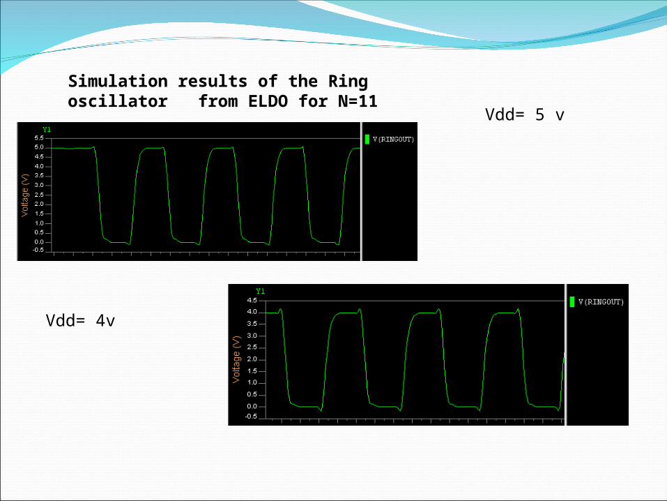
Vdd= 5 v
Vdd= 4v
Simulation results of the Ring oscillator from ELDO for N=11

Vdd = 3 v
Vdd=2v

Vdd= 1 v
Vdd = .9 v
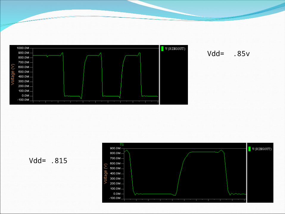
Vdd= .85v
Vdd= .815

Vdd (volts) Rise time fall time
5 0.08ns 0.07ns
4 0.10ns 0.07ns
3 0.11ns 0.1ns
2 0.2ns 0.1ns
1 0.8ns 0.34ns
0.9 1.73n 0.76ns
0.85 3.2ns 0.82ns
0.815 5.21ns 1.83ns
N=11
The rise times and fall times of the oscillator increases with a decrease in supply voltage which indicates that the delay of the gates increases with a decrease in the supply voltage.

Vdd (Volts) Frequency Power
5 826MHz 3.382mW
4 698MHz 1.7mW
3 562MHz 702uW
2 367MHz 187uW
1 64.9MHz 6uW
0.85 19MHz 1.18uW

Vdd (Volts) Frequency Power
5 826MHz 6.61mW
4 698MHz 2.93mW
3 562MHz 1.212mW
2 367MHz 323uW
1 64.9MHz 10.36uW
0.85 19MHz 2.038uW
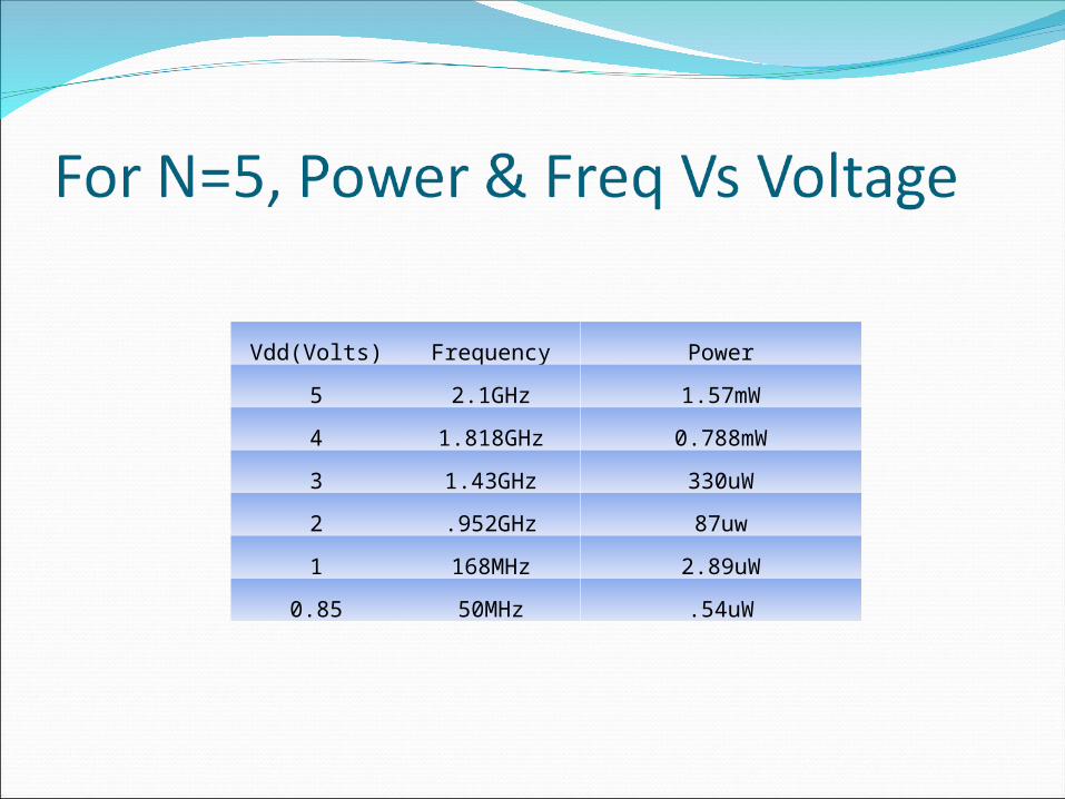
Vdd(Volts) Frequency Power
5 2.1GHz 1.57mW
4 1.818GHz 0.788mW
3 1.43GHz 330uW
2 .952GHz 87uw
1 168MHz 2.89uW
0.85 50MHz .54uW

X-Axis: Voltage(Volts)Y-Axis: Power(uW)

X-Axis: Voltage(Volts)Y-Axis: Frequency(MHz)

As the number of gates increases the Average power increases proportionally.
X-axis: Number of gates Y-axis: Average Power
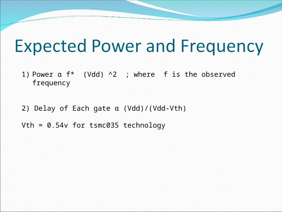
1) Power α f* (Vdd) ^2 ; where f is the observed frequency
2) Delay of Each gate α (Vdd)/(Vdd-Vth)
Vth = 0.54v for tsmc035 technology
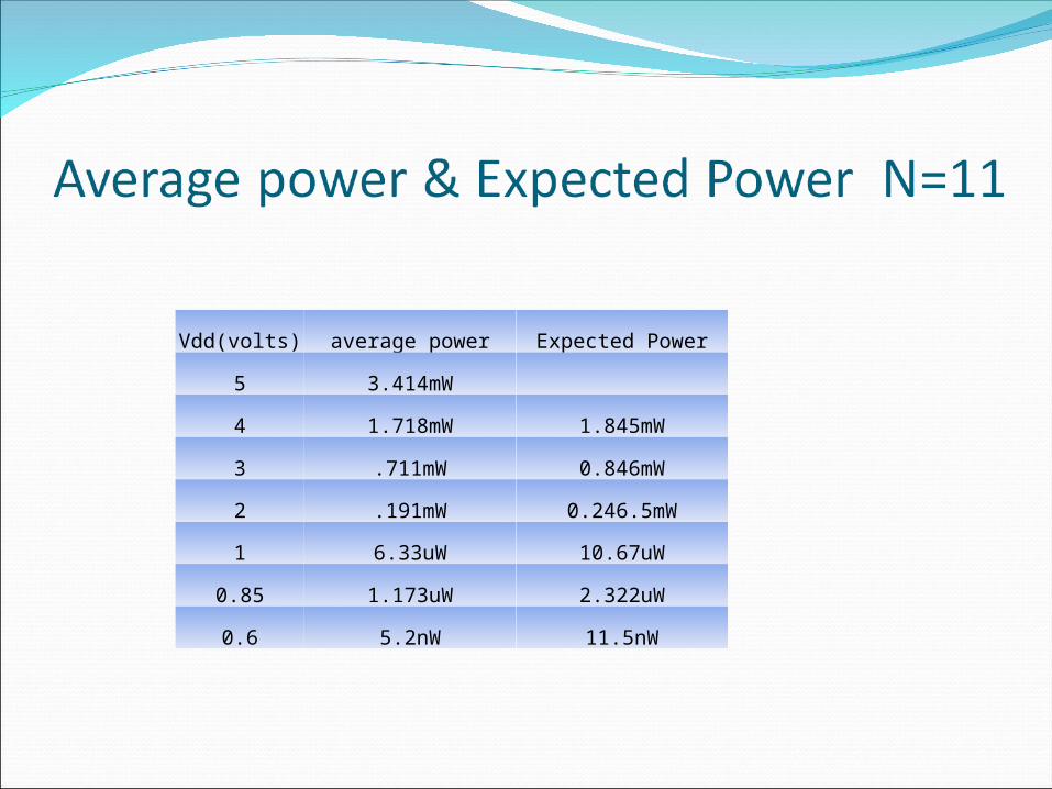
Vdd(volts) average power Expected Power
5 3.414mW
4 1.718mW 1.845mW
3 .711mW 0.846mW
2 .191mW 0.246.5mW
1 6.33uW 10.67uW
0.85 1.173uW 2.322uW
0.6 5.2nW 11.5nW
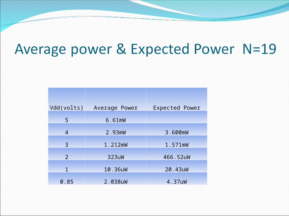
Vdd(volts) Average Power Expected Power
5 6.61mW
4 2.93mW 3.600mW
3 1.212mW 1.571mW
2 323uW 466.52uW
1 10.36uW 20.43uW
0.85 2.038uW 4.37uW
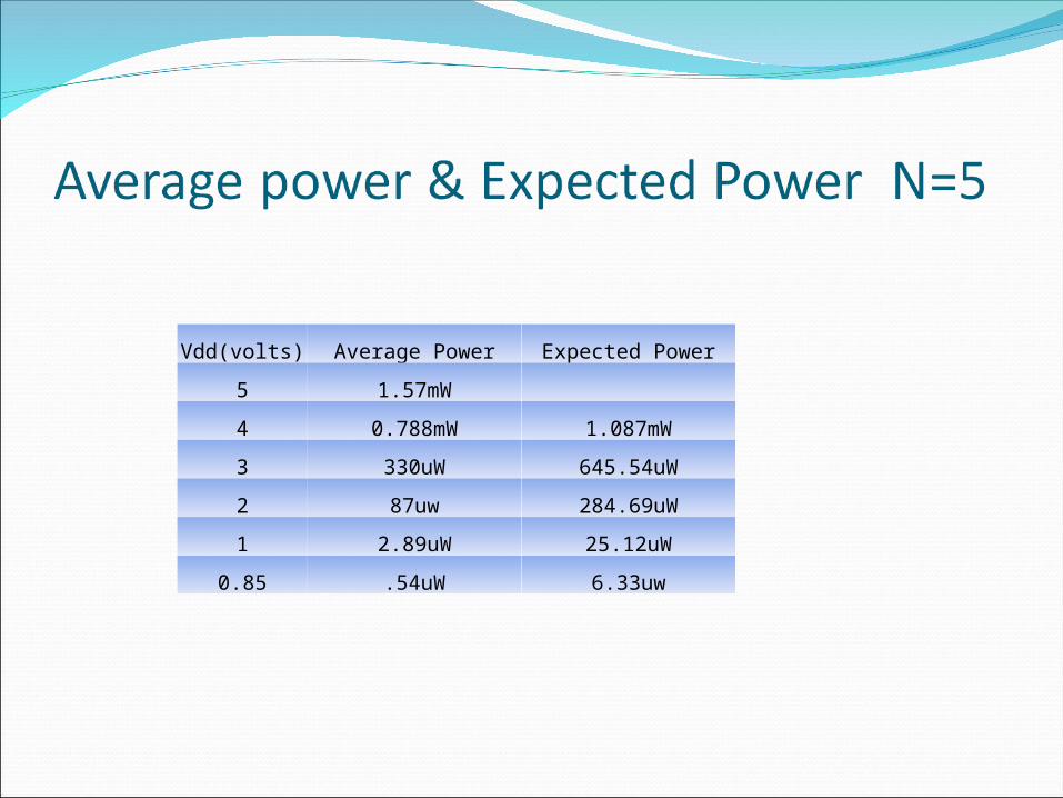
Vdd(volts) Average Power Expected Power
5 1.57mW
4 0.788mW 1.087mW
3 330uW 645.54uW
2 87uw 284.69uW
1 2.89uW 25.12uW
0.85 .54uW 6.33uw

VDD (Volts) frequency Expected Frequency
5 1.389GHz -
4 1.176GHz 1.34Ghz
3 0.956GHz 1.277Ghz
2 .627GHz 1.136Ghz
1 .109GHz .716GHz
0.85 .0327GHz .568GHz
0.6 0.326MHz .155GHz

Vdd(Volts) Freq Expected Freq
5 826MHz
4 698MHz 800.9MHz
3 562MHz 759.3MHz
2 367MHz 675.8MHz
1 64.9MHz 425.9MHz
0.85 19MHz 337.7MHz

VDD(volts) Freq Expected Freq
5 2.1GHz
4 1.818GHz 2.036GHz
3 1.43GHz 1.93GHz
2 .952Ghz 1.718GHz
1 168MHz 1.08GHz
0.85 50MHz 858MHz

• If the Vdd is changed from 5v to 0.85V there is a power reduction of about 99.9%, but the frequency of oscillations is decreased by 76% .
•The Frequency of oscillations decreases as the number of gates in the oscillator increases.
•The Power consumption increases in proportion to the number of gates in the oscillator.
•The Observed frequencies are lesser than the expected frequencies due to large delays in the gates at low operating voltages.

1. Fall 2007: ELEC6270 Low Power Design Electronics Class Slides from Dr. Agrawal
2. Fall 2007: ELEC6250 Computer Aided Design of Digital Logic Circuits Lectures 4,23 from Dr. Nelson’s Class slides.
3. http://www.iue.tuwien.ac.at/phd/martins/node46.html