ELCT FOUNDATION REPORT AUS Army Corps uJT 0 81992 REPORT of Engineers S A Fort Worth District...
156
AD-A256 259 ~fii I I~III ~I~ li~OTCFINAL@S -U--.-. l ELCT FOUNDATION US Army Corps uJT 0 81992 REPORT of Engineers S A Fort Worth District COMPLETION OF EMBANKMENT OUTLET WORKS AND SPILLWAY COOPER LAKE SULPHUR RIVER, TEXAS MAY -1992 9-68 L _ _ _ _ _ _ _ _ _ _ _ _ _ _ _ _ _ _ _
Transcript of ELCT FOUNDATION REPORT AUS Army Corps uJT 0 81992 REPORT of Engineers S A Fort Worth District...

AD-A256 259~fii I I~III ~I~ li~OTCFINAL@S
-U--.-. l ELCT FOUNDATION
US Army Corps uJT 0 81992 REPORTof Engineers S AFort Worth District
COMPLETION OF EMBANKMENTOUTLET WORKS AND SPILLWAY
COOPER LAKESULPHUR RIVER, TEXAS
MAY -1992 9-68
L _ _ _ _ _ _ _ _ _ _ _ _ _ _ _ _ _ _ _

CORPS OF ENGINEERSFORT WORTH DISTRICT, TEXAS
FINALFOUNDATION REPORT
COMPLETION OF EMBANKMENT, OUTLET WORKS AND SPILLWAY
V
COOPER LAKE
MAY 1992

TABLE OF CONTENTS
PARAGRAPH TITLE PAGE NO.
I INTRODUCTION
A Project Location and Description IB Construction Authority 2
C Purpose of Report 2D Location of Structures 2E Contractors and Contract Supervision 2
II FOUNDATION EXPLORATIONS
A Investigations Prior to Construction 4B Investigations During Construction 4
III GEOLOGY
A Regional Geology 5
B Site Geology and Character of Foundations 6
IV EXCAVATION PROCEDURES
Excavation Grades 12B Unanticipated Foundation Conditions 13
C Unwatering Provisions 14
D Overburden Excavation 15E Rock Excavations 15F Foundation Preparation 17
V FOUNDATION ANCHORS
A Spillway 18
B Outlet Works 19
VI FUTURE CONSIDERATIONS
A Reservoir Seepage Through Embankment 19
B Spillwav Anchor Foundations 19

ILLUSTRATIONS
FIGURE NO. TITLE
1 As-Built Repair in Spillway Key Excavation2 Approach Cut Off Key - Outlet Works3 Outlet Works Tower Transition to Conduit4 Outlet Works - Forming for Conduit Collar5 Outlet Works Conduit - Monolith 16 Outlet Works - Conduit - Protective Slab
-8 Outlet Works9 Spillway - General View10 Spillway Weir Foundation11-12 Spillway Weir11-14 Spillway - Machine Use in Cutting Keys15 Spillway - Cut Off Key Excavation16 Spillway - Slide Block in Key Excavation17-26 Spillway Wall Footings27 Spillway Chute and Stilling Basin28 Spillway Chute Cross Drains2'-30 Spillway Chute Foundation
ii

PLATES
NO. TITLE
i Lake Map and Vicinity Map2 General Plan3 Embankment Plan and Profile4 Typical Embankment Sections5 Outlet Works Intake Structure Plan and Section6 Outlet Works Intake Structure Typical Installation7 Outlet Works - Conduit Details
8 Outlet Works - Stilling Basin - Plan and Section9 Spillway - Plan10 Spillway - Weir and Slab Plan11 Spillway - Weir and Slab Details12 Regional Geology13 Geologic Profile - Axis of Dam14 Geologic Profile Outlet Works15 Geologic Profile Spillway16 Geologic Profile - Right Abutmenti7 Inspection Trench Foundation - Sta 0+00 to Sta 6+0018 Inspection Trench Foundation - Sta 6+00 to Sta 17+00I1 Inspection Trench Foundation - Sta 17+00 to Sta 23+0020 Inspection Trench Foundation - Sta 23+00 to Sta 3+50 (Local)21 Inspection Trench Foundation - Sta 3+50 (Local) to Sta 8+50 (Local)22 Inspection Trench Foundation - Sta 8+50 (Local) to Sta 37+50 (Emb)23 Inspection Trench Foundation - Sta 39+75 to Sta 45+752, Inspection Trench Foundation - Sta 45+75 to Sta 58+0025 Inspection Trench Foundation - Sta 58+00 to Sta 70+0026 Inspection Trench Foundation - Sta 70+00 to Sta 82+002.7 Inspection Trench Foundation - Sta 82+00 to Sta 94+00)8 rnsppction Trench Foundation Sta 94+00 to Sta 106+00
9Q Inspection Trench Foundation - Sta 106+00 to Sta 118+00Outlet Works Foundation - Sta 74+53 to Sta 77+75
11 Outlet Works Foundation - Sta 77i75 to Sta 80+74"32 Outlet Works Foundation - Sta 80+,0 to Sta 82+12.833 Spillway Foundation - Plan34 Spillway Centerline Profile
3ý Boring Location Map - I36 Boring Location Map - II3 Boring Location Map III38-',4 Logs of Boring
iii

PREFACE
This report was prepared in the Geotechnical Branch, EngineeringDivision, Fort Worth District. The report was authored by ProjectGeologist, George Ruede, under the supervision of the Chief, EngineeringGeology Section, Robert C. Behm, and Chief of the Geotechnical Branch,Melvin G. Green
District Engineers for the Fort Worth District during construction ofCooper Lake were Colonel John E. Schaufelberger, Colonel William D. Brown,and Colonel John A. Mills. Mr. Terry Coomes was Chief, EngineeringDivision. Area Engineer for construction was Mr. James D. Lesley andlater Mr. Jobie R. Smith. Project Engineer was Mr. Kenneth S. Bain whowas succeeded by Mr. Donald R. Clements.

COOPER FOUNDATION REPORT
I INTRODUCTION
A. Project Location and Description of Features. Cooper Dam is
located in northeast Texas on the South Sulphur River at river mile 23.2upstream of Wright Patman Dam and Lake. It is situated in Delta andHopkins Counties, about 4 miles southeast of the town of Cooper, and 13miles north of the town of Sulphur Springs. See Plate 1 for the lake and
vicinity map.
1. Embankment. The earthfill embankment, which isapproximately 28,911 feet long, has a maximum height of 68 feet above the
floodplain, a top of dam elevation of 464.5 feet (after overbuild), and a
crown width of 30 feet. The embankment is constructed of three different
materials which are placed in zones paralleling the centerline of the dan.
The outermost zones upstream and downstream from the centerline are
comprised of semicompacted fill. Immediately interior from each of the
s2micompacted zones is a random fill zone, both upstream and downstream.
The central or core zone consists of compacted impervious clay fill. SeePldtes 3 and 4 for plan and sections of the embankment.
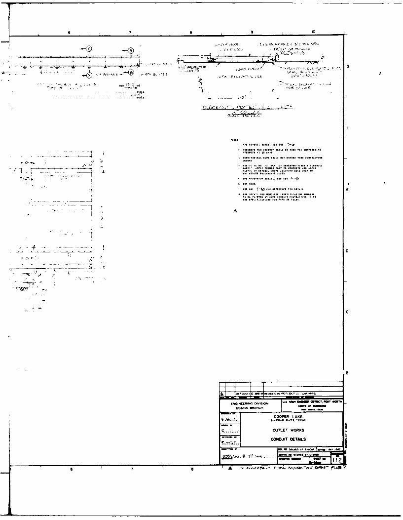
2. Outlet Works. The cut-and-cover outlet works consists ofan approach U-wall structure, a gate control tower, a conduit, a dischargechute, and a stilling basin. See Plates 5, 6, 7, and 8 for plans andsections of these structures. The approach, tower, and conduit areconstructeJ on an unreinforced concrete slab 3-1/2 inches thick whichextends oitward beyond the structures a distance of 3 feet. The slab inturn protects the excavated surface of the foundation. The chute and
stilling b :sin structures are constructed on an unreinforced protective
concrete slab 3-1/2 inches thick, which in turn is founded on a 12-inch
thickness of filter sand placed on the surface of the foundation fromstation 80+73.5 at the headwall downstream to approximately station81097.5. Sand-filled drains approximately 4.0 feet in width are located
alongside the chute and stilling basin between these same stations. Fromoutlet station 81+97.5 to the cutoff key at station 82+06.5, the structureis constructed on an unreinforced, 3-1/2 inch thick protective concreteslab which in turn covers the excavated foundation surface.
3. Spillway. The spillway walls are 505.0 feet long, extending
from spillway station 5+21.0 upstream to station 10+26.0 downstream.Downstream from the weir, the interior slab flooring the spillway is
comprised of six lanes crossing the spillwav chute from wall footing towall footing. Each slab lane crossing the spillway is supported by a1.0-foot thick blanket of filter sand with a covering of 3-1/2 inches ofprotective concrete immediately upstream from each concrete key which is
embedded in the foundation or a cross drain as at station 9+63 in the
stilling basin. However, the filter blanket which is designed to drainthe foundation between keys and adjacent to L'e cross drain in thestilling basin, is present downstream only as far as station 9+87.
1

Downstream from this location the slab is supported directly by thefoundation to the cutoft key at the downstream end of the stilling basin.There are a total of 870 anchors constructed in the chute and stillingbasin to protect the interior slab from the effects of uplift should thefilter blanket beneath the slab become ineffecLive. The anchors areembedded 14 feet into the foundation and grouted in place. Each anchor isoriented at 900 to the foundation surface. The top of each anchor is bent90' to parallel the concrete slab and to increase embedment in the slabconcrete. See Plates 9, 10, and 11 for spillway plan and sections.
B. Construction Authority. Congressional authorization forconstruction of the Cooper Lake and Channels is contained in Public Law218 (Chapter 501), 84th Congiess, approved August 3, 1955.
C. Purposes of the Report. This report has been prepared pursuantto Regulation No.1110-1-1801 to record foundation conditions before andduring construction. The report is also intended to record unanticipatedfoundation conditions encountered during construction, and methods used toovercome them.
D. Location ot Structures.
I. Embankment. The earthfill embankment commences effectivelyat the P.T. station of the south access road on the right abutment whichis station 14+60.30, or approximately embankment station -15+43.30. Theembankment then extends to the spillway, across the backfilled outletworks, accross the valley of the South Sulphur River to the left abutment,then along the gently rising land surface of the left abutment toembankment station 281+50.95 where it ends. Total length of theembankment is approximately 28,911.25 feet, neglecting the interior widthof the spillway.
2. Spillway. The spillway is located on the right abutment,the centerline of which is at embankment station 30+84.4. This point isalso spillway station 6+40 and lies between the approach walls, upstreamfrom the weir. An inspection trench into foundation material, whichelsewhere follows the centerline of tbh embankment, is offset 80 feetupstream from the embankment alignment, crossing the spillway beneath bothaDproach wall monolith I and monolith 2.
3. Outlet Works. The outlet works is also located on the rightabutment, 440 feet toward the valley from the left spillway wall. Thecenterline of the outlet works is at station 38+74.34 of the embankment.This is station 70+00.00 of the outlet works conduit. See Plate 2 for theproject layout.
E. Contractors and Contract Supervision. Cooper Dam was constructedunder two contracts. The initial contract was not completed due todefault of the contractor. Uncompleted work was added to the second andiinal contract.
2

1. Initial Embankment Contract.
Contract Number: DACW63-87-C-0019Contractor: Caliber Construction, Inc., Conroe, TexasScope of Work: Construction of embankment from station 217+05 to the endof the embankment at station 281+50.95Contract Award Price: $666,778.20Date of Notice to Proceed: January 7, 1987Date of Acknowledgemnt of Notice to Proceed: January 15, 1987Work Commenced: January 15, 1987Work Ceased: October 22, 1987 due to default of Caliber ConstructionCompanyTotal Payment: $242,034.48
2. Completion of Embankment, Spillway, and Outlet Works.
Contract Number: DACW63-87-C-0085Contractor: Luhr Brothers, Inc. of Columbia, Illinois.Contract Award Price: $41,364,970.35Date of Notice to Proceed: August 7, 1987Date of Acknowlegement of Notice to Proceed: August 13, 1987Work Commenced: August 14, 1987Payments to October 15, 1990: $36,156,109.50 (includes 34 modifications
to the contract, one of which was to remedy default of Calibercontract: $396,801.37). Net without modificaions:$35,759,308.13.
Subcontractor to Luhr Brothers: Martin K. Eby Compan;-, Inc. of Wichita,Kansas, for fine-grading structure foundations, construction ofconcrete structures and slabs, and mechanical and electrical work forthe outlet works.
Subcontractor to Martin K. Eby Company (operation of a concrete batchplant): Lattimore Materials Company of Mckinney, Texas.
Subcontractor to Martin K. Eby Company (subsequent to completion of outletworks, spillway, and service bridges): Westbrook Ready-Mix Company ofSulphur Springs, Texas.
Subcontractor to Luhr Brothers, Inc: (for installation of foundationinstrumentation, e.g. settlement plates, inclinometers, andpiezometers) Woodward-Clyde Consultants of Denver, Colorado.
3. Contract Supervision. Both the initial and completioncontracts listed above were administered by the North Texas Area Office ofthe Fort Worth District, first under Mr. James D. Lesley, Area Engineeruntil his retirement, then by Mr. Jobie R. Smith, Area Engineer. The on-site Cooper constiuction office was administered by Mr. Kenneth S. Bain,Project Engineer until his death on 11 October 1989. Mr. Donald R.Clements was appointed Project Engineer to complete construction of CooperDam and Lake.
3

II FOUNDATION EXPLORATIONS
A. Investigations Prior to Construction. An extensive investigationof the Cooper site was conducted by the New Orleans District between 1957and 1974. During this investigation approximately 249 borings weredrilled at the dam site and in the borrow areas. Work on Cooper Projectwas not prosecuted during the period between 1974 and 1984 whileenvironmental effects of the project were litigated. During this periodthe Cooper project was transferred to the Fort Worth District.Approximately 74 additional borings of all types were drilled by the FortWorth District between 1984 and 1986. The reader is referred to thepublication Design Memorandum No. 3 (Revised), Cooper Lake and Channels,Embankment, Spillway, and Outlet Works, Volumes I and 2, January 1986 bythe Fort Worth District for further details of these investigations.Boring plan and boring logs are shown on Plates 35 through 54.
B. Investigations During Construction. The possibility ofunderseepage through the sand stratum and through fractures in theoverlying limestone stratum in the higher elevations of the rightabutment, particularly in the vicinity of the spillway and outlet works,was considered during construction. The sand stratum, approximately 10feet in thckness in this area, is partially cut off in the spillway properby clay backfill in the deep inspection trench and the weir. The upper.most permeable part of the sand, and the overlying fractured limestonebed, are cut off by a wedge-shaped strip of select impervious clayembedded in the sand stratum across the entire chute slope of thespillway. The concern was that lake water entering the outcrop of thesand stratum, or possibly the fractured limestone in the upstream slopesof the abutment ridge, or water standing in the spillway, mightcommunicate downstream to seep or flow from the surface of the embankmentslope. Another concern was that due to these factors, and particularlythe presence of the strip of select impervious across the chute slope, thefoundation in the downstream slope of the right abutment ridge might notbe in a sufficiently drained condition during normal or flood poolc-nditions. The area of possible downward percolation of lake water inthe spillway is approximately 52,800 square feet and lies between thespillway approach apron and the backfilled deep inspection trenchupstream. There will be 6 feet of water ponded here during conservationconditions. The principal remedy employed to reduce lake water entry intothe sand and fractured limestone beds in the foundation upstream was toplate any outcrops with clay. This investigation was designed to locatethe outcrop of the sand stratum and the limestone, if present, in theabutment slope, upstream. Three very shallow trenches, dug with atractor-mounted backhoe, were excavated in the upstream slopes of theabutment ridge a f . hundred feet upstream from the spillway. Thetrenches were only &,•ep enough to penetrate all disturbed material andexpose the natural in-situ materials beneath. The first trench, locatedabout 350 feet west .left) and 450 feet upstream from the spillway, foundthe sand stratuwj at an elevation very close to that at which it wasanticipated. The next tdo trenches nearer the spillway were commenced atelevations at least 5 feet above the anticipated elevation of the top of
4

sand as a precautionary measure. The second trench was located so as toalign with the inside face of the left spillway wall. The bottom of thistrench dropped 18 feet in elevation along its path down the abutmentslope, finding the top of a sand stratum at the base of the abutment ridgeslope at an elevation approximately 10 feet lower than the sand stratum inthe first trench. The third trench, located between the first twotrenches, found only clay and did not find the lower sand because it didnot terminate at quite as low an elevation at the base of the ridge slope.Results obtained in the three trench excavations seemed to indicate thata fault exists a short distance upstream from the spillway. With the sandstratum upstream offset 10 feet lower in elevation, and the sand and itsimmediately overlying impervious clay appearing to be the same materialsas those present in the spillway (but without the limestone bed betweenthem), it is believed that the sand stratum in the spillway proper iseffectively cut off from dire• t recharge from the lake in this area. Aswill be seen subsequently under the title Structure, this natural cut offof the sand probably persists eastwardly up the abutment toward station0+00. The practical consequence of the fault cutoff of the sand stratumin this area was that only a small area of sand outcrop need to be platedwith impervious clay to reduce infiltration of lake water between thespillway and the fault. This area lies west of the spillway between thespillway and the outlet works approach channel where the land surface isa slope. Later, after the outlet approach channel had been excavated, thedown-faulted portion of the sand stratum was found in the channel slopeswhere it ended abruptly at the anticipated location of the fault.Locations of the exploratory trenches, the fault, the spillway, and theoutlet works approach channel are shown on Plate 3.
III GEOLOGY
A. Regional Geology. Cooper dam is situated in the northwesternquadrant of a regional structural feature called the East Texas Basin.The same feature is sometimes referred to as the East Texas Syncline. Itis a large basin occupying nearly all of East Texas, but open on the southto merge with structure of the Gulf Coast. Peripheral to the basin on thewest and north sides is a system of predominantly down-to-the-coast (downto the south), normal (gravity) faulting which extends well beyond theEast Texas Basin eastward into Louisiana and Mississippi and beyond, andsouthward and south westward for a considerable distance beyond the basin.As expected, all of the formations other than those of surficial material(overburden/alluvium), dip into the basin more steeply than theinclination of the ground surface giving rise to the youngest bedrockunits being at the ground surface in Lhe central part of the basin.Bedrock formations in and about the aea of Cooper Dam and Lake dip southand slightly to the east by rea'on of their being situated in thenorthwest quadrant of the basln. Stratigraphically, the bedrockformations croping out in the £dst Texas Basin range in age from UpperCretaceous to late Tertiary See Plates 12 through 16 for regionalgeology map and geologic sections. Additional description of the regionalgeologic setting can he found in the previously referred to documententitled Design Memorandum No. 3 (Revised), Cooper Lake and Channels,
i5

Embankment, Spillway, and Outlet Works, Volumes 1 and 2. January 1986 by
the Fort Worth District, Corps of Engineers.
B. Site Geology and Character of Foundations.
1. Physiography. Physiographically the uplands of the rightabutment form a gently rolling, relatively level land surface of erosionaltopography. A moderately steep slope divides the right abutment from thefloodplain of the South Sulphur River valley in the vicinity of embankmentstation 43+50, a short distance west of the outlet works. This slopepersists upstream as a landform for several miles. The bottom of theSouth Sulphur River valley is comprised of approximately two levels ofvery gently sloping land surface which is depositional topography. Theleft abutment of the dam consists of a gently rising land surface. Thisslope also extends upstream for several miles bordering the lake thoughthe slope there is dissected by a few prominent tributary stream channels.As in the instance of the right abutment, this abutment is comprised oferosional topography, but differs from the right abutment by beingtopography developed on the dip slope of the bedrock formations.
2. Overburden. So far as can be discerned, there is littlealluvium on either abutment. Nearly all of the overburden on bothabutmentn is residual soil because it is the product of extreme weatheringof the bedrock in-place. Alluvial and residual soils are shown onaccompanying plates portraying geology of the inspection trench. Residualsoils in the abutments of the dam almost universally consist of clay.Soils which were present in the inspection trench in the bottom of theSulphur River valley are all alluvial clay, though there is some sand andsilt deeper in the valley alluvium. Discriminating between alluvial soilsand residual soils is done here for two reasons, because residual soilsare more closely related to the bedrock beneath them than to the alluviumand because residual soils have a history of overconsolidation.
3. Bedrock Classification and StratigraphY. Bedrock isclassified into three principal types of material for purposes of thisreport: shale (the dominant bedrock lithology), limestone (a minorconstituent of the bedrock sequence) , and sandstone of which there is verylittle in the sequence. Though it is a soil, sand occurs in the bedrocksequence in the uppermost slopes of the right abutment, particularly underthe spillway and again immediately beneath the embankment at the top ofthe abutment left (west) of the outlet works excavation. It should benoted that both the limestone bed and the sandy clay overlying it wereremoved from the right abutment west of the outlet works, leaving the sandstratum in-place, prior to placing embankment fill.
Stratigaphi 1ily, five rock units are involved in the foundation of'he dam and its uctures. They are, from oldest and deepest to youngestand nearest the surface: the Marlbrook Formation, the NevlandvilleFormation. the Navarro Group (undivided), and the Midway Group which inthis area consists of the Kincaid Formation overlain by the Wills PointFormation. The last two, the Kincaid and the Wills Point are shown on
6

Plate 12, but are undivided in mapping by the State of Texas (TexarkanaSheet of the Geologic Atlas of Texas, published by the Bureau of EconomicGeology). The first three of these rock units are Cretaceous in geologicage and the Midway Group is of Tertiary geologic age. All of these unitsare comnrised predominantly of shale. Since so little thickness of thescunits is involved •n the foundations of the spillway and the outlet worksexcavations, and since there are not sufficiently different physicalcharacteristics between the Kincaid and the Wills Point to accuratelydistinguish them, no further use of formational names will be made, otherthan to say that both the Kincaid and the Wills Point m.y be present inthe spillway/outlet works area, but that from lithology encountered inexcavations, it is doubted that the Wills Point is present. Locally, justoutside the spillway and outlet works area, the limestone bed at the topof the right abutment is missing from the geologic section. In the deepinspection trench immediately east of the spillway in the vicinity ofembankment station 24+50, the 2 to 3 feet thick limestone bed thinseastward then disappears, being replaced by boulders, cobbles, and gravel.aýl of limestone), which are cverlain by the sandy clay bed that overliesthe limestone elsewhere. In an area where the limestone and its detritaliemnants are both absent, the sandy clay lies directly on the sand bed.This relationship is that of a typical erosional unconformity of at least,ocal extent. The limestone bed is also missing from the geologic sectionin the area explored with backhoe trenches upstream from the spillway.The limestone bed was also missing from the section in the approachcrhannel of the outlet works. Relationships in this area will be describedagain under Bedrock Structure.
The principal variations within the shales exposed in excavatiuns forthe spillway and the outlet works are relatively thin layers defined bydifferences in sand and/or lime content of the shale matrix. The generalrelationship is very low sand content in the lowest elevations of thespillway and the chute and stilling basin of the outlet works, the sandcontent increasing upward to the sand bed near the top of the abutment.An insitnificant oddity in the section is the presence of near-roundcoriretionarv masses of limestone the size of large cannon balls whichoccur in a few of the zones of very limy shale. The presence of thelimestone masses may explain why core descriptions from borings indicatedthe presence of a number of thin limestone beds which on excavation wereseen to be isolated bodies of limestone rather than beds. A number oflimestone beds described in boring logs did not seem to correlate orproduced erratic structure when correlated. Only one limestone bed ofsignificant extent was found in excavations for the spillway and theolutlet works.
Z'. Bedrock Weathering. Bedrock is weathered to a greater depthbeneath the land surface in both abutments than it is elsewhere. Thiscondition is normal and typical because the abutments have been subject toweathering for a much longer time than has bedrock beneath the flood-plain, which is the most recently eroded bedrock ani is covered byalluvium. The depth to which bedrock is weathered was >est exhibited inthe spillway and outlet works excavations and in the desp portion of the
7

inspection trench on the right abutment. This can be seen in sectionalviews of the as-built deep inspection trench on Plates 20, 21, and 22.The depth to which we.rthering extends elsewhere in the right abutment andin the left abutment as well, can be seen to only a very limited extentbecause of the shallow depth of the trench at those sites. In thespillway portion of the deep inspection trench, weathering extends fromthe surface downward nearly to the base of the sand/sandstone interval.From the outlet works excavation west to the end of the right abutment(toward the South Sulphur River) the base of bedrock weathering did notappear in the inspection trench. Here all of the sand/sandstone bed isweathered and the trench is based in residual clay soil. See Plate 23 fora sectional view of the area west of the outlet works.
5. Bedrock Structure. The principal geologic structure presentat the dam and lake is regional dip. In the vicinity of the South SulphurRiver between the Highway 19 crossing, a short distance downstream fromthe dam, and the city of Commerce, a few miles upstream from the dam,regional dip is directed approximately south 200 east. No reliable datafor determining regional dip of the bedrock strata are available, mainlydue to faulti.ig. The site of the dam and lake is on or very near thenorthern margin of the Talco-Luling-Mexia fault system, because severalfaults of this collective system have been mapped in the bedrock in theriver bottom and the right abutment. The principal engineering effect ofthe faults is vertical offset of the bedrock strata. Considering thenature of the bedrock materials, no significant leakage of lake water isexpected to occur along fault planes. See Plate 12 for the location offaults mapped near the dam site. A fault probably crosses the inspectiontrench between embankment station 15+67 and embankment station 22+67because the limestone bed near the top of the right abutment isapproximately 16 feet lower in elevation here than at station 24+55 in thedeep inspection trench. The difference in elevation of the limestone bedat the two places cannot be explained by dip. The most likely location ofthe fault seems to be near station 16+00. See Plates 18, 19, and 20 forthese relationships. This fault, being down-thrown on the side away fromthe South Sulphur River valley, indicates that the middle fault shown atthe same location on Plate 12 is not shown correctly with its down-thrownblock on the river valley side of the fault. Existence of two otherfaults, one on each side of this the middle fault, could not be confirmedor denied because of excessive weathering of bedrock or the bedrock beingburied too deeply by alluvium to be encountered in the inspection trench.
Evidence of a probable fault was found in the right slope of theoutlet works approach channel. A thin bed of sand, approximately 7 feetthick, which had lost some of its thickness through erosion, was found inthe right slope at outlet station 71+00. The bed extends north toward theoutlet works as far as station 72-&.27 where the bed abruptly terminates.No fault plane could be identified at the bed termination, because thematerials there are all weathered to residual soils, but it is believedthat the sand bed is terminated by the offset of a fault. The sand bedwas excavated along the the side of the approach channel with a notch-shaped cut and the material removed was replaced by clay. The ground
8

surface away from the cut and cover was also plated with clay (3- to 4feet thickness) as additional protection against infiltration of lakewater in case the sand bed was not totally offset by faulting in thisimmediate area. The sand bed is not terminated in the left slope of theapproach channel opposite station 72+27, but there the bed rises inelevation toward the outlet works (downstream) forming a gentle flexure.From this it is inferred that the fault ended in material removed inexcavating the approach channel and its displacement is made up by theflexure in the left side of the approach channel. It was not firmlyestablished that a fault exists upstream from the spillway and outletworks as suggested here, but a line drawn to connect the most likely faultlocation in the inspection trench (station 16+00) with the termination ofthe sand bed in the right slope of the approach channel renders conditionsfound in the backhoe trenches easy to explain: The two trenches whichfound only clay at the elevation of the target sand bed of the spillwayproper are upstream from the fault line as drawn and appear to be on thedown-thrown side of the fault because a sand bed was found there at alower elevation. The trench which found sand at the approximate elevationof the target sand in the deep inspection trench is downstream (toward thespillway) from the fault line as drawn and presumably is on the upthrownside of the fault. Elevation of the top of the sand bed is 422.3 feet andelevation of the bottom of the sand bed is 419.3 feet, both elevationscomparing closely with those of the sandbed in the upstream slope of thedeep inspection trench (see Plate 13). It should be noted that thelimestone bed normally overlying the sand bed is missing here as it iseast of the spillway in the deep inspection trench. In any event theeffect of these relationships saved much construction effort plating thetarget sand outcrops upstream with 3 to 5 feet of impervious clay. Thefact that sandy clay overlying the sand bed here is down-faulted supportsthe contention that it is a residual material derived from bedrock ratherthan alluvium. This is predicated on the generally acceptedinterpretation that faulting here is not of recent geologic age.
Both the spillway and the outlet works appear to be on the same faultblock. Stratigraphic and structural relationships of the bedrock couldbest be seen when the rough cut excavations were first completed.Bedrock strata in the rough-cut spillway slopes revealed themselves bytheir differential resistance to erosion. One could follow severalindividual beds entirely across the spillway excavation. There were nofault offsets apparent. Approximate correlation could be made between thespillway and the outlet works. No fault offsets were apparent in theoutlet works excavation either. It was visually apparent that bedrockstrata dip across the spillway from the right side to the left side, butit was not so apparent whether the bed rock strata dipped upstream ordownstream. Perspective within the spillway and along the downstream fallof the outlet works conduit complicated judgement visually. Sectionalviews of bedrock and residual soils in the deep inspection trench showclearly that these strata are not structurally planar. Rather, theseviews indicate a number of minor local warps. The simplest portrayal ofstructural dip of the bedrock in the spillway and outlet works is to treatthe bedrock as being part of a single fault block. The average componentof dip of the base of the limestone bed, measured in the upstream slope of
9
L _ _ _ _ _ _ __ _ _ _ _ _ _ _

the deep inspection trench between local station 1+99.5 and local station8+99.5 is to the west (toward the valley) at the rate of 1.55 feetvertically per 100 feet horizontally. The average component of dip alongthe centerline of the spillway between the weir and the deep inspectiontrench is upstream at 0.9 feet vertically per 100 feet horizontally.Similarly, though at a much lower elevation, the component of structuraldip along the conduit foundation between station 76+40.5 and station78+43.5 is upstream at the rate of 0.13 feet vertically per 100 feethorizontally on the right side of the conduit and 0.24 feet vertically per100 feet horizontally upstream on the left side of the conduit, But thecenterline of the spillway and the centerline of the outlet works are notparallel and can be seen to converge downstream at an angle of 10.8degrees (see Plate 3). Taken together, these data suggest that thedirection of average local dip of the bedrock and residual soils in thisfault block is westward and slightly upstream along the embankmentalignment as it crosses the spillway. Very few fractures were mapped inthe foundation of the chute and stilling basin of the outlet works. Nonewere mapped in the approach, gate tower, or conduit structure foundations.See Plates 30, 31, and 32 for the outlet works foundation. Quite a fewfractures were mapped in the foundation of the spillway. Thepreponderance of them were located in the stilling basin and in the lowerslopes of the chute where the shale has the lowest sand content of anyexcavated, unweathered material. Shale in this portion of the spillwayappeared to have had some low-grade cleavage developed within it. Whilequite a number of the fractures mapped obviously existed prior toexcavation, quite a number also appeared to have developed from using ascraping tool (a backhoe) for fine grading the foundation surface of thecleavable shale. These fractures did not extend to any significant depthinto the shale. See Plate 33 for the foundation of the spillway. Themost significant fracturing from an engineering standpoint seemed to bethose fractures encountered during initial excavation of the right end ofthe cutoff key at the downstream end of the spillway slab. At thislocation several slices of foundation shale failed into the key excavationvery shortly after it was excavated with a toothed ditching machine(Vermeer T-650). In all instances the shale failed on what appeared to beslickensided cleavage surfaces dipping downstream more gently than thesteep upstream 4V on 1H slope of the key. Even though the fractures werenot apparent when the key was first excavated, it seems likely that theyexisted prior to that time because of the slickensiding on the failuresurfaces (pre-failed shale). One failure occurred immediately followingexcavation. A second failure consisting of several thin slices of shaleoccurred after the earlier thicker failure slices blocking the excavationhad been cleared and preparations were being made to place structuralconcrete. The failure section was between offset 270 right and offset 344right of the spillway centerline. The downstream vertical surface of thecutoff key is at spillway station 10+10. The contractor (Martin K. EbyCo.) repaired the excavation and placed structural concrete as indicatedin his sketch (Figure 1).
6. Ground Water. A minimum of ground water data are availablefrom which to develop more than general conclusions. The expected
10

condition of the ground water table being a much subdued reflection ofsurface topography seems born out at the site of Cooper Dam. The onlyissuance of ground water from the foundation during construction was fromen exploratory core hole low in the parabolic chute slope of the outletworks. Similarly in the spillway, ground water seeped from a fewfractures low in the chute slope. In both instances the top of the groundwater seepages was very little above the elevation of the South SulphurRiver. Though fractures in the bedrock shale appear to drain well, itseems unlikely that any individual fractures extend entirely through thecore of the right abutment. Even if a system of interconnected fracturesextends through the core of the abutment, it seems unlikely such a systemwould allow significant seepage through the abutment because of the lengthand tortuosity of the flow paths.
7. Leaching and/or Solution Activity. The only conditionnoticed which may indicate leaching of the foundation involves the sandbed at the top of the right abutment as seen in the spillway, deepinspection trench, and the top of the abutment immediately west of theoutlet works excavation. This bed is almost clayless and free draining atits top just below the limestone bed, and is progressively more clayeydownward through the bed. In its basal portion it is a very poorlycemented, weathered, argillaceous sandstone locally. Whether thismaterial was deposited as described or was changed due to downwardleaching of clay is not important as properties of the material ratherthan its history are of primary interest here.
8. Engineering Characteristics of the Foundation Materials.Based on field investigations, laboratory testing, and engineeringjudgement, the parameters adopted for embankment design are as follows.The parameters selected are the same as those determined by NOD except forthe shear strengths of the floodplain alluvium. Examination of shearstrength data by SWF indicated that a non-zero angle of internal friction(phi) could be used for Q-strengths of the upper and lower alluvium. Avery small but needed value (1.70) was assigned.
Embankment Foundation Design Parameters.
(1) Upper Alluvial:
Moist unit weight 125 pcfSaturated unit weight 130 psf
Angle of internalType Strength Cohesion, tsf friction, degrees
Q 0.85 1.7R 0.4 12.0s 0.0 20.0
11

(2) Lower Alluvial:
Moist unit weight 125 pcfSaturated unit weight 130 pcf
Angle of internalType Strength Cohesion, tsf friction. degrees
Q 0.4 1.7
R 0.4 12.0
S 0.0 30.0
(3) Kincaid Formation:
Moist unit weight 120 pcfSaturated unit weight 125 pcf
Angle of internalType Strength Cohesion, tsf friction, degrees
Q 4.0 0.0
R 3.0 19.0
5 0.0 30.0
IV EXCAVATION PROCEDURES
A. Excavation Grades. Specifications for excavating foundations inthe spillway and the outlet works required that a minimum of 2 feet ofundisturbed material above all final grades be left in-place until finalfinished grades were to be excavated, except in the case of hard rocklayers. The final 2 feet of material was to be excavated in a continuousoperation within a period of 4 hours. If an unfavorable local weatherforecast existed, the final 2 feet of excavation was to be postponed.These provisions were intended primarily to protect the rough-cutexcavated surfaces from either drying or slaking when exposed to weatherfor a protracted period of time. Secondarily they were to protect thefinished surfaces from erosion. They were first applied in gradingfoundations of the outlet works and were found to significantly inhibitthe contractor's normal work cycle. After being excavated to finishgrade, the freshly exposed surfaces were also required to be protected (tobe described subsequently) then covered with protective concrete, filtermaterial, or compacted fill within 4 hours. These specifications reducedthe amount of foundation area which could be completed in a daily workcycle of 8 to 10 hours. The specification which required excavation of
12
I

the final 2 feet of material within 4 hours was modified to provide thatthe first 1.5 feet of the final 2.0 feet to be excavated could be removedI day and the final 0.5 feet of material removed the following morning,immediately followed by sealing the foundation and placement of concrete,filter material, or compacted fill on the foundation. This changeoccurred while excavating conduit monoliths in the outlet works. Themodification resulted in an increase in production without inducing anyvisible deterioration of the foundation. Very few areas in either theoutlet works or the spillway were significantly overexcavated, none ofwhich were by direction. The first of these areas was the site of thecollar foundation at the downstream end of the transition section from thegate tower to the conduit. The contractor extended flat-bottom gradingdownstream beyond the transition, through the site of the collar, into theupstream end of the first conduit monolith, thereby removing foundationshale needed to form a V-bottom for the collar and conduit monolith. Theoverexcavated shale was replaced by backfill concrete, formed to supportthe structural concrete of the collar and the conduit monolith. Shalecomprising the foundation of spillway wall footing L-14 was overexcavatedas much as 2 feet. This apparently occurred because the area was one inwhich excavating equipment turned sharply while rough-cutting the stillingbasin. The overexcavated shale was replaced by over-thickening the slabcf protective concrete covering the shale. Similarly, the few otherlocations where the structure foundations were overexcavated werecorrected by thickening the filter sand or protective concrete, whicheverdirectly covered the foundation.
B. Unanticipated Foundation Conditions Encountered DuringConstruction. The cutoff key beneath the end sill at the downstream endof the spillway slab was first excavated from offset 344 feet right tooffset 294 feet right (50 feet) on 25 October 1988. The upstream slope ofthe key was cut first using a self-propelled Vermeer T-650 ditchingmachine (effectively a saw). The upstream slope of the key is inclineddownstream at the rate of 4 feet vertical on 1 foot horizontal. This cutwas approximately 5.5 feet deep and its width was approximately that ofthe cutter head. Large splinter-shaped pieces of shale slid out of theupstream slope into and across the cut before the intended full length ofthe first cut was completed. The vertical downstream face of the key wasthen cut and the slide blocks were removed from the key excavation. Theupstream slope of the key was then laid back to a slope of 1 foot verticalon I foot horizontal, which was the approximate dip of the planes on whichthe blocks of shale had slid downstream. The shale was then sprayed withAerospray 70 to protect it from drying. Very shortly after this a numberof large but thin (3 inches thick?) she:ets or slices of shale slid out ofthe upstream slope of the key, crossing the key excavation. The keyexcavation was then refilled with a temporary backfill of shale rubblebecause of imminent rain showers. The slide planes on which the shalemoved were poorly slickensided fractures dipping downstream at aninclination of roughly 451. The foundation shale in this portion of thespillway appeared to have a poorly developed cleavage dipping in the samedirection and to the same degree as the slide planes. The key foundationwas not reopened and repaired until I December 1988. Figure 1 shows the
13

method of repair utilized by the contractor. No further slides orproblems of this sort were experienced in the remaining excavation of thekey or other foundation 2xcavations.
C. Unwatering Provisions. No problems caused by flows of groundwater requiring special control measures were experienced duringconstruction of the outlet works, spillway, or inspection trench. Therewere, however, isolated instances of ground water seepage from fracturesin the shale foundations of the outlet works chute and the spillway chute.Pre-construction water level data from borings on the outlet worksalignment have indicated the water table to be at approximately elevation390 in the uppermost part of the chute slope. Pre-construction waterlevel data from borings in the spillway indicated that the water tablelikely was between elevation 394 and elevation 401, just below the middleof the slope of the spillway chute. Excavation of the chute and stillingbasin of both the outlet works and the spillway apparently lowered thewater table in both instances as expected, but there was no opportunity tomeasure the altered water table. The only flow of ground water of anysignificance experienced during excavation of the outlet works chute wasfrom a boring which had been made into an observation well (pre-construction) located about one-third of the way up the chute slope fromthe bottom of the stilling basin. This boring was plugged in the processof preparing the foundation. There was very little seepage of groundwater from fractures in the foundation of the outlet works chute andstilling basin, none of which was difficult to route or control.Similarly, there were only a very few, isolated, local seeps of groundwater which emanated from fractures in the lowermost slopes of the chuteor the bottom of the stilling basin of the spillway. The general absenceof foundation materials capable of either storing or transmittingsignificant quantities of ground water below the pre-construction watertable made unwatering largely unnecessary during construction of theembankment, outlet works, and spillway. Unwatering in the form of routingof runoff was employed during construction of the outlet works andspillway. No such provision was necessary in the inspection trench as allbut the deep portion of the inspection trench was open for extremelylimited periods of time. A few storms caused significant amounts ofrunofF to flow througvh the inspect-ion trench however, from the east end ofthe deep portion of the trench (abutment end) westward to the outlet worksexcavation where the flow emptied down the right sideslope of theexcavation into the outlet works drainage system at the toe of thesideslope. These flows exceeded the capacity of the outlet works drainagesystem on at least one occasion. Runoff protection in the outlet worksexcavation <-onsisted of two ditches, one at the toe of each of thesideslopes of the excavation. The ditches commenced in the vicinity ofthe upstreaw end of the gate control tower and extended downstream. Theditches ended initially in sumps immediately downstream from the futuresite of the conduit headwall. The ditches were subsequently extendedfarther downstream as the chute and stilling basin were excavated, ending4n a large sump just beyond the left downstream corner of stilling basin.A large diesel-powered pump was maintained at the sump. The upstream endof the outlet works excavation was protected by a dike. Runoff routing in
14

the spillway was essentially limited to a collector ditch located justdownstream from and parallel to the cutoff key beneath the endsill of thestilling basin. A large sump wi.h a diesel-powered pump was maintained atthe east end of the collector ditch immediately downstream from the end ofthe right wall footing. No peripheral ditches were employed outsideeither the right or left wall footings. The stilling basins of both theoutlet works and the spillway were protected downstream by a broad,unexcavated area on which a downstream-curving dike was constructed witha top elevation of 407 feet to prevent any inundation by flooding of theSouth Sulphur River. The spillway and outlet works discharge channelswere excavated downstream from this dike early in the construction of boththese structures.
D. Overburden Excavation. Excavation for foundations comprised ofsoil was done entirely by conventional means. The inspection and deepinspection trenches were excavated utilizing scrapers with push cats(dozers) and blades (road maintainers). Backhoes were used onlyinfrequently. Most of the scrapers used on the job required use of atleast one push cat (usually a D-Q Caterpillar dozer), but there were alsotwo paddle-wheel (self-loading) scrapers in use on the job.
E. Rock Excavation. With the exception of limetone at the top ofthe right abutment, all structure foundation materials classified as rockwere excavated by the same means that were used to excavate overburdenmaterials, namely scrapers, waintainers, and backhoes. As described aboveunder Excavation Grades, materials in the spillway and outlet worksclassified as rock (excepting limestone) were excavated so as to leave aminimum thickness of 2 feet above finished grade. This excavation wasdone with scrapers. Excavation of the final 2 feet of rock to reachfinished grade for structure foundations was done with .a backhoe. Theinitial 1.5 feet of this excavation was done with the backhoe bucket teethexposed for efficient excavation. The final 0.5 feet of this excavationwas with a smooth, sharpened, steel bar mounted on the backhoe bucket ina manner to cover the bucket teeth and scrape a smooth surface on thefoundation.
1. Blasting. Blasting was done at the site of the spillway toexcavate a ±3-foot limestone bed to final grade in the chute slope, alsoat the location of both the right and left wall footings, and in slopes tobe "ackfilled against outside both walls. Limestone in the spillway dipsto the west (to the left). Consequently, it was encountered atprogressively lower elevations to the west across the chute slope and inslopes exterior to the wall footings. Limestone in the uppermost slopesof the outlet works excavation was excavated by blasting. Blasting wasrequired to remove limestone from the deep inspection trench betweenembankment station 24+50 amd embankment station 43+10 near the west end ofthe right abutment. Except for two blasting caps used for each end of theinitiating row of each shot, no electric blasting caps were used. Thefollowing two types of blasting were done to remove the average thicknessof 3 feet of limestone in excavations for the spillway, outlet works, anddeep inspection trench.
15
I--

a. Presplitting. Pre-splitting shot holes were drilledinclined at I foot vertical on I foot horizontal (steeper than I on 1.5slideslopes of the deep inspection trench and the 1 V on 3.5 H sideslopesof the outlet works excavation and the chute and sides of the spillwayexcavation).
(1) Spillway. Presplitting across both the chute slope and thesideslopes of the spillway was done at finished grade at the elevation ofthe top of the limestone. Presplitting was also done in an extensive areaupstream from the top of the chute slope. This area lies between theoutside of the right wall footings and a line a short distance inside theright wall footings where the limestone was above slab grade, and in thesame area between the approach apron upstream from the weir and the deepinspection trench.
(2) Outlet Works. The outlet works excavation was outlined bypresplitting at finished grade at the elevation of the top of thelimestone. (Note: The outlet works excavation was open at both ends.)
(3) Deep Inspection Trench. The deep inspection trench wasoutlined at finished grade applicable to the elevation of the top of thelimestone upstream from the spillway and in that portion of the trenchlocated west (riverward) from the outlet works to the end of the rightabutment. (Note: Both trench segments are open-ended.)
(4) Presplitting Details.
Hole size: 2-1/2 inchesHole spacing: 3 feet, center to center.Depth of holes: 3 feet (to bottom of limestone bed).Explosive charge per hole: 1 inch x 4 inches, 75 percent Extra Gel locatedin bottom 1- to 1-1/2 feet of hole, hole stemmed to ground surface.Trunk line from explosive charge to row line: 50 gr. E-Cord (trade name).Row line connecting trunk lines: 75 gr. H.D. Permaline.Row line shot with one zero-delay electric blasting cap at each end ofline (only electric caps used). All shot holes drilled during each daywere loaded with an explosive charge and shot the same day.
b. Production Blasting.
(1) Spillway and Outlet Works. Production blasting within pre-split outlines listed above. This included removing all limestone betweenthe spillway chute and the right abutment hillside downstream, and in partof the area from the weir upstream sufficient to permit reaching gradefrom outside the right wall and its footings westward until the limestonewas below grade.
(2) Right Abutment. Production blasting necessary to removeall limestone from the top of the right abutment west (riverward) of theoutlet works excavation. This was a change of design and followed
16

excavation of the deep inspection trench in the same part of the rightabutment.
(3) Production Blasting Details-
Hole size: 2-1/2 inches.Depth of holes: 3 feet (to bottom of limestone bed).Explosive charge per hole: Primer: 1 inch x 4 inch Extra Gel; Filledbottom I foot to 1-1/2 feet of hole with S.E.I. from Strawn Explosives,Inc. (this explosive is anfo).Stemmed portion of hole: Top I to 1-1/2 feet of hole. Trunk line fromexplosives to row line: 50 gr. E-Cord (trade name).Row line connecting trunk lines: 75 gr. H. D. Permaline.Connectors joining row lines and providing successive shot delays: 50millisecond (ms) delay connectors.Initiating row line shot withe electric blasting cap at each end of row.First shot pattern used: 4 feet x 5 feet, produced rock of too small size.Second shot pattern used: 7 feet x 9 feet, produced adequate-sized rock.Quantities of materials used for all blasting (approximate, includespresplitting): 44,000 feet of 75 gr. H.D Permaline (row-shootingprimacord), 22,000 feet of 50 gr.E-Cord (dowm-hole and trunk-shooting primacord), 250 connectors of 50millisecond delay, 23,600 lb. of S. E. I. (anfo blasting mixture).Blasting ratio: 23,600 lb. explosive/38,000 cu. yd. of in-place rock0.62 lb. per cu. yd.
F. Foundation Preparation. Aside from fine-grading foundationsusing a back hoe with a smooth blade covering the bucket teeth, foundationpreparation consisted almost exclusively of spraying shale foundationswith a commercial product known as Aerospray 70 Binder, sold by theAmerican Cyanamid Company of Wayne, New Jersey. Aerospray 70 Binder is apolyvinyl acetate emulsion resin, containing approximately 600 totalsolids. The purpose of treating shale foundations with this product wasto vastly reduce the drying rate of shale exposed in finished excavations,allowing more foundation to be prepared at a time increasing constructionefficiency. Aerospray 70 was applied as a mixture of bulk liquid andwater in a ratio of 1 to 1. This fluid mixture was applied using portabltýspraying equipment, the nozzle of which produced a relatively coarse sprayto reduce air-borne drying of the spray and to produce better wetting ofthe shale surfaces involved. Thinner mixtures were tried but gave toolittle protection. In a few instances such as during hot weather, a 1/2to 1 ratio of Aerospray 70 to water was used. It was necessary to respraya foundation infrequently. The product Aerospray 70 was a successor tothe product Aerospray 52, formerly sold by American Cyanamid Company.Aerospray 70 appeared to be somewhat less effective in preventing dryingof shale foundations than was Aerospray 52, and consequently was appliedas a slightly heavier coating. Aerospray 52 had been used inconstruction of Granger and Aquilla dams in the Fort Worth District and onseveral construction projects in the Huntington and Baltimore districts.
17

V FOUNDATION ANCHORS
A. Spillway. A total of 870 anchors was installed in the spillway,connecting the structural concrete slab to the foundation. They wereinstalled from the top of the chute slope at the downstream edge of theweir at approximately spillway station 7+29.8 to station 9+67.0 in thestilling basin and from the right wall footings to the left wall footings.All anchors were oriented normal to (at 900 to) the surface of thestructural concrete slab. Prior to construction of the permanent anchors,two test anchors were constructed, one at station 7+80 near the top of thechute slope 4 feet left of the centerline and the other at station 9+42 inthe stilling basin, 4 feet right of the centerline. Both test anchorswere constructed in 6-inch diameter drilled holes to the required minimumdepth of 14 feet into the foundation. Each anchor was subjected to apull-out test and each anchor demonstrated required resistance to pull-out. A generalized description of the anchors and their constructionfollows: Installation of an anchor commenced with placing a sleeve oftubular material larger than 6 inches in diameter through the filter sandblanket and cementing it into the top of the shale. Next, a slab ofprotective concrete 3-1/2 inches thick was placed on top of the filtersand blanket with the sleeve extending slightly above the surface of theprotective concrete. The sleeve can be made of any of a variety ofmaterials such as sheet metal ducting, but 8 inch diameter corrugatedplastic pipe was used here. It was to serve as a conductor pipe throughthe protective concrete, the filter sand blanket, and the top of thefoundation shale to seal off the filter sand to prevent sand from thefilter blanket from being entrained in the return air flow when drillingthe anchor hole. Without sand entrainment no void will develop in thefilter sand blanket beneath the protective concrete slab. Followingdrilling and cleaning of the anchor hole, the assembled anchor is placedin the hole and the hole filled to the top of the protective slab withgrout. The anchors themselves consist of #9 rebar stock, bent 900 at thetop for embedment in concrete of the structural slab. A 1/2-inch diametergrout pipe, long enough to protrude above the protective concrete and toreach downward to within the bottom 1 foot of the anchor, is wired to eachanchor along with two "spacers," which should have been identified on theplans by their functional name, centralizers. The centralizers are wiredto each anchor I foot and 13 feet above the bottom of the anchor. Thecentralizers used in the Cooper spillway were prefabricated units. Eachcentralizer was made of relatively thin but stiff round rod stock as fivepieces welded together. The top and bottom pieces were open rings, witha gap sufficient to allow them to be slipped on the anchor rebar. Threeshort lengths of the same sized rod stock, were bent in the shape of ahump in a way that the ends of each piece align with each other. Thethree hump-shaped pieces of rod stock connect the two rings of eachcentralizer and are welded to the rings in such a way that the hump-shapedpieces are spaced around the rings 1200 apart with the hump portionsoutermost. When the finished centralizers are oriented with the hump-shaped pieces parallel to the anchor rebar, the gap in the two rings is
18

aligned with each other and the centralizers can be slipped on the anchorand wired to it. The anchor will slide in or out of the hole easily withthe hump-shaped pieces acting like sled runners. In the past,centralizers have been fabricatec with horizontally oriented centralizingrings, the rings looking very much like rings on a ski pole when theanchor is vertical. Centralizers of this design tend to hang on defectsin the wall of the hole and are awkward to use.
B. Outlet Works. The use of anchors was not specified for structurescomprising the outlet works.
VI FUTURE CONSIDERATIONS
A. Reservoir Seepage Through Embankment. lt is now believed that asmall potential for seepage of lake water from the downstream slope of theembankment betwzon Lhz spillway and the outlet works exists whei, the lakeis at conservation pool or higher levels. The estimated risk of seepageof lake water through the shallow sand bed in the foundation wassignificantly reduced by the discovery of the fault-offsetting of the sandbed between upstream slope of the abutment ridge and the spillway, and byplating the sand bed with an impervious clay fill in the limited areawhere it cropped out in the abutment slopes upstream. Though the risk oflake .;ater seepage from the embankment downstream appears to be much lessthan originally thought, the possibility of seepage is not considered tohave been eliminated. If seepage does develop, the sand bed between theweir and the wedge-shaped strip of select fill may develop a low head ofwater due to the inability of the filter blanket to completely drain thesand.
Entrance of lake water into the sand bed upstream and itstransmission to the downstream embankment slope of the right abutment left(west) of the outlet works appears to be unlikely because all but a thinsliver of the sand is cut off by the backfill of the deep inspectiontrench and because this portion of the right abutment ridge is completelyencased in compacted embankment fill.
Recommended Observations. It is recommended that periodicobservations of water levels in piezometers P-1 through P-5 be made, withemphasis on piezometers P-1 and P-5 (in the sand bed). These piezometersare located in a row oriented upstream/ downstream, in the area of concernbetween the spillway and the outlet works. The piezometers should predictthe likelihood of underflow to the downstream slope of the embankment. Itis also recommended that the downstream embankment slopes in the vicinityof station 16+00, and also to the immediate left of the outlet works, beobserved for the possible commencement of seepage, particularly when thelake level rises above conservation pool.
B. Spillway Anchor Foundations. "Wall packing," while drilling 6inch anchor holes in the chute and stilling basin of the spillway,indicated the possibility of unseen foundation damage. Other evidenceindicated possible displacement of filter sand of the drainage blanket in
19

the stilling basin shortly after drilling commenced. "Wail packing" meansthe collectng and packing of drill cuttings between tl-e drill rod, onwhich the bit is mounted, and the wall of the hole. "Wall packing" stopsor g-catly reduces the return flow of air which normally blows drillcuttings from the hole. Obstruction of the return air flow causes a buildup of air pressure in the hole below the "wall pack". "Wall packing"became so severe during the early stages of anchor drilling thatadditional -utters were welded to the to_ of the drill bit so that the bitcould be drilled out of the hole through the "wall pack". The need fordrilling out of the hole diminished somewhat through time. The renteddrill appeared to be one intended primarily for drilling hard rock with abit less than 6 inches in diameter. It operated by both hammer action androtation, hammer action on a rotary drill bit not being efficient.Diameter of the drill rod appeared to be slightly over 1 inch. The aircourse down the center of the drill rod was so small that one could notquite insert the end of his little finger in it, which was responsible forthe small return air flow and an unknown pressure drop in the system.Though air pressure at the bottom of holes during drilling could not bemeasured, nor reliably calculated, concern for foundation damage fromdrilling was generated by the fact that air pressure at the discharge ofthe nearby air compressor suppying the drill was seven times that whichwould be necessary to lift foundation shale, filter sand, and theprotective concrete slab commencing at a depth of 15 feet, if a horizontalfracture was present at that depth which drilling air could enter. Directevidence of excessive air pressure affecting the foundation and/or thefilter blanket consisted of bubbling water emerging along the downstreamedge of key concrete located at the base of the chute slope while drillingthe first anchor holes in the stilling basin near the right wall. Inaddition, a small amount of filter sand had been distributed on top of theprotective concrete slab and key concrete along the junction between thetwo at the same location. These conditions suggested that the foundationshale penetrated by the anchor holes might have been pneumaticallyfractured during the process of drilling anchor holes and that anyfractures produced probably would not be filled with grout used tobackfill the holes after the anchors were installed. Foundation designerswere consulted with a view to requiring the contractor to substitute adifferent drill which would not risk foundation damage. It was agreedthat there was some risk of creating new fratures in the foundation shale,also possible risk of minor displacement of filter sand. While it wouldhave been preferable to have a different drill used, one which would notresult in "wall packing" of drill cuttings. it was believed that the riskof unacceptable foundation damage was not sufficiently great to justifypaying the contractor significantly more money to substitute a differenttype of drill for the one he was using.
Recommended Observations. All observations to detect foundationdamage from anchor drilling are of necessity indirect since the foundationis covered with concrete. Once Cooper Lake becomes operational, thespillway stilling basin will be filled with water except for rareinstances when pumping and cleaning is required, during which time anydeformation of the concrete can be observed. The slab on the chute slope
20

above the water surface in the stilling basin can be observed at all timeswhenl no flood water is passing over the weir. It is recommended thatconcrete of the spillway chute be observed for cracking and deformationimmediately following cessation of any flood flows over the weir, butotherwise only during normal routine maintenance inspection. The stillingbasin should be similarly inspected during periods when it is dewateredand cleaned of sediment. It appears likely that the time of greatestlikelihood _ problems stemming from foundation damage or filter blanketdamage would be when passing a flood, during which vibration from rapidlymoving water may occur. If sand composing the filter blanket shouldsettle the slightest amount at this time, some contact between the slabconcrete and the filter sand will be lost, the sand may shift down slopeLn the chute, and the slab will be supported only by the anchors in anyareas where contact between the sand and the slab is lost.
21
CORPS OF ENGINEERS U S ARM)I - I

MARTIN K. EBY CONSTRUCTION CO., INC. JOB No.-
PROJECT: BY CKD
LOCATION DATE _SHEET NO. ___OF
YI
6 w1 4 (
O F.
- . N-'" l
.! . ,\•1-5(1/86

CORPS OF ENGINEERS U. S. ARMY
FIGURE 2. Approach cut off key of outlet works. Upstreamis to left. Note film of Aerospray 70 coating shale foun-dat ion.

CORPS OF ENGINEERS U. S ARMY
FIGURE 3. Downstream end of tower transition to conduit.Collar (open area) overexcavated requiring concrete buildup to replace shale foundation. Downstream is to right.
FIGURE 4. Forming for collar structural concrete afterbuild up of backfill concrete beneath collar forming.Downstream is to right.

CORPS OF ENGINEERS U. S. ARMY
r
FIGURE 5. Monolith 1 of outlet conduit, looking upstreampast collar at end transition into construction of gatetower base. Note block out for downstream collar.
FIGURE 6. Looking upstream through conduit protectiveslabs and collar block outs toward outlet gate controltower construction.
_ ___ ___

CORPS OF ENGINEERS U_ S. ARMY
FIGURE 7. Looking upstream in outlet excavation. Note:Protective concrete of chute and stilling basin. Rain run-off control ditches can be seen on each side of the exca-vat ion.
FIGURE 8. Looking downstream into stilling basin. Noteelevated pump and pipe reaching down into sump for run-off at left, far corner of stilling basin (beyond farleft corner of filter sand area).
--_--------_ __ _

CORPS OF ENGINEERS U. S ARMY
/
FIGURE 9. General view of spillway during final excavationnd placement of filter sand and protective concrete. Anchor
hole drilling can be seen on the protective concrete in thehicýher elevations of the chute.
CORPS OF ENGINEERS U. S. ARM'
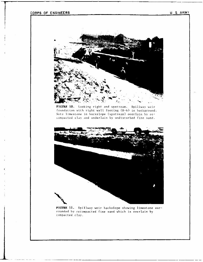
FIGURE 10. Looking right and upstream. Spillway weirfoundation with right wall footing (R-6) in background.Note limestone in backslope (upstream) overlain by re-compacted clay and underlain by undisturbed fine sand.
FIGURE 11. Spillway weir backslope showing limestone sur-rounded by recompacted fine sand which is overlain bycompacted clay.

CORPS OF ENGINEERS U. S. ARMY
FIGURE 12. Spillway weir showing limestone in backslope,
sand in bottom, limestone at near break in slope, whichis overlain by undisturbed sandy clay (beneath two nearfigures). Sample sandy clay above limestone in back-
slope.
FIGURE 13. Ditching machine used to excavate key foundations
in the spillway.

CORPS OF ENGINEERS U. S ARMY
FIGURE 14. View of cutters of Vermeer T-650 used to
excavate key foundations in the spillwav.

CORPS OF ENGINEERS U. S. ARMY
FIGIURE 15. Initial excavation of cutoff key
at downstream right end of spillway slab (end
sill key). This view is at the time of firstmovement of slide blocks. Movement of thin
slices of shale into the excavation occurredlater after the key had been cleared of slideblocks and the upstream slope re-excavated to
a IV on 1H slope.

CORPS OF ENGINEERS U S ARMY
FIGURE 16. Excavation of cut off key atdownstream right end of spillway at thecommencement of slide block movement intoexcavation.
h i, . .. . ........... . . ..... ..... ..... . ................ . . . .. . . ...

CORPS OF ENGINEERS U, S. ARMY
FIGURE 17. Downstream portion of spillway wall footingR-!V (end wall footing of right wall). Form boards inip,ý cen~ter, nt photo (along downstream edge of R-15)
11tmiit coemnencement of the cut off key where it wraps'1round t he d(ie;T'nst!ream end of the key. Note fracture-
e"'~'P r'rlovmts of foundation shale.

CORPS OF ENGINEERS U. S. ARMY
FIGURE 18. Downstream portion of spiliway wall footingR-15 (end wall footing). Form boards shown along theleft side of the cleaned foundation outline the cutoffkey along the downstream end of wall footing R-15.Note fracture patterns and pullouts crossing foundationof downstream half of R-15. (Cutoff key starts inupper left corner of foundation, as seen here, extendstoward viewer to near corner, then extends to right innear ground to out of sight behind unexcavated shale.This is side of R-15 nearest spillway centerline.

CORPS JF ENGINEERS U S ARM"Y
FIGURE 19. Upstream portion of spillway wall footing R-15
(end wall footing). Form boards seen here are along theside of R-1' nearest the spillwav ccnterline. Note the
tin of the form boards in the upper right. This isthc locaion where the cut off key turns 90' from the
eOde o. R-l; toward the spillwav centerline as the cut- , i.-,w as [he end sill key). Fractures and
pr:~l 't~ *' i'n ire, ;re also to be seen in Figures 17 and
n.1

CORPS OF ENGINEERS U. S. ARMY
FIGURE 20. Upstream portion of spillway wall footing R-15(end wall footing). This is a close view of fractures
shown in figure 19. Fractures are in sets, dipping in op-posite directions.
FIGURE 21. Upstream portion of spillway wall footing R-15.View looking down dip slope of fractures dipping upstream.

CORPS OF ENGINEERS U. S. ARMY
FICUJRE 22. Upstream portion of spillwaywall footing R-15. Form boards seen at topof Photo are those of Figures 20 and 21.Looking toward spillway centerline.
I _ _ _ _ _ _ _ _ _ _ _ _

CORPS OF ENGINEERS U. S. ARMY
FIGURE 23. Spillway wall footing R-15. Note wheel mountedpiece of equipment in lower portion of Photo with angle ofform boards immediately behind. Form board angle and foun-dation fracture trend are those of previous Photos. Frac-tures in the darker shale to the right (upstream) in theuT%>tream portion of R-15 dip downstream (to the left).

CORPS OF ENGINEERS U S ARMY
FIGURE 24. Foundation of spillway wall tooting R-14. R-15is covered by protective concrete. Note: Board angle seenhere is not that of previous photos. Previous form boardangle is beyond stacked shovels on concrete in this Photo.
FIGURE 25. Foundation of wall footing R-14, looking up-Stream. Note paucity of fractures in foundation shale.This is typical of shale foundations of the lower chuteand stilling basin of the spillway.

CORPS OF ENGINEERS U. S. ARMY
FIGURE 26. Looking downstream along right wall footingfoundations. R-15 (concrete-covered) and R-14, withmanhole and drain blockouts are in stilling basin. R-13(not finished) straddles stilling basin/chute junction.
FIGURE 27. Portion of spillway chute and stilling basin.Chute slope following construction of keys crossing spill-way, but prior to excavation for filter/drainage blanket.
.... ........ . ....

CORPS OF ENGINEERS U. S. ARMY
FIGURE 28. Typical cross-drain foundation in spillway chute.
FIGURE 29. Materials comprising chute foundation acrossspillway in Lane F.

CORPS OF ENGINEERS U. S. ARMY
FIGURE 30. Typical foundation in F Lane of spillway chute.

2 3456
I A'
':I -2ri
AA-
r- o

6 89
- 0
804~~~ 0.AV
~~0E 4r5
Nk
WON ARE I
-a ' 4' zOP~vTO
POOL~t 4000£NG'E( 0S~wl ro, tor. D
COC- OI Emq 4 0 r
-- - - - - - - - -R-P- -
4 COMPLETION OF
GOVERNMENTMENT PROLPERNTOULEYWR
LAKE MAP AND VICINITY MAP
0-10 "Sea 4t
I -.. e

4- 4"
A \A
' '~0~> ANNE,
-4, -. - ---------
-O --- ---- --
4W4
5.t .4C V bIý,

6 7 0
) 4/6?n
•.- ~~ ~ .... ..... . ,.-
q.. .'- @.
•• c.
~-..,DOOMf 0,
FORTONT',
\V
cm'. . vwa
COOPE LAKEI 'NiL P RETIER 'E% ,5
INITIAL EMBANKMENT
!- ,-t 91 AND DIVERSION CHANNEL
,, ,< ,,2. GENERAL PLAN
S......... ... C.....b C-... ."I"•,ll, , ,
------------

V -V
45c.
-As
A-4
~~15,
44
4 4,

6_ 7F G
IKE- E.FL-CATO-
cTAI 7f'34 1
/ -.
*Of A* 4,W: Li. - rp
rVLL-L, WW
7.1
A. I
x ~ ILL60 ON t'1'*EtE.
15,t~.o 3 iO fAV~7-
t ^LI a- ,Pe"'- TICIA ¾ RC "66. "'N~~~~~~E r. 15.<FFF _4
'A.C W~ li JM 74 i '0'-1NI LIW) CN tZ
5Y T 0-4.00 TO STAJC4 '*.00
.3~~~~~~~t r-i-,. '"*'66If"C6/ - srs..C.
4A'-~ 3.ACA.£66 -t
F-~ ~~~~~~~~~ -------------- .6'6*$ '~C- f 6 f.5*I
Z:7___ ___________~ 4~'< F'' C 1 ~ -~
6 0"-

5
�-�-- >-
- �$-Z�- �
- - ' -.7--. - -
I - - -
- - - I -I
- t
-� I ___ ____
- 4 - -. �'1-
4 5
9

T- 6vrG1:
-2_
-IF
u I- AR _ _ _ MMT OT OT
-m4s OF E
-- - - - r I ' L . e- - j k r T ý L

2 3 4 5 6
t A
I A
- I I �A p
A A
- _#40 '+ JO I' CO '�C�OLTh' �,C 29 -- �o.-jo-'.�
B' �
0 ¾AK* C
:4 t��•ft�
0', �
-� �
- -.-- - t
- CC',-
4 'A' � -a-. JO'," -
�- � F
P _____________________________________________________________
��LC- 'A -' -. - -.--.-- - - -
- �" -4
4
I�" 2 3 k.'' � 5 /�I'�' 6

5 6 , 8 9 0)
t 9
i:V
- I
//
6 44c C)C
____ 1_
- - • 3. . - --, : -,• '•- •t5•4 U L T W R S IT K T U T R-of "v I ) IF-
ENGINEERING DIVSION Ul Ift 0"411 O"MiD "T 10IT"
D-Sr.N BRANCN aOS 0 D
- - - COOPER LAKE
SULNELJ* RIVER V EXSA
4 . - - ' - . 55f/.'" -,A OUTLET WORKS-INTAKE STRUCTURE
* ~ - -APPROACH STRUCTURE~ ~--4*-PLAN AND SECTION
IL~~ ls - 56Ig A" toI ~ E 1 -Tj /.,IE ¶)CA "tb)

2 3 4 5 6
.1
-�-.�_ -�
.4.
.4- -� 000
4�.A0� 2AA�iev
1*�4��-'� -A4�A��S � ---- I- � >-4..
4c� -�
* . I. .�- 0
- . .- � � -! 044.�-O �4-0 � � 0
0
A-44- I
4. 4-,.
* i I �
- �
� '-4-"44 �
4 ..�4
f� 4�AT� �'�4
.2
�.4�44 *�4�4- �.--. -fl �
I: \TIK �-r ir�
4- *'.. -
'�- r4 3 6' 3�
I I L44-.�..d44I � � I -- - -
irn(-�>3 I
4... 4 .. � a ''� 44 4-..
-� 4; -V .1� 4�4S4-444�44< *00'4- *�. 4; . --
-- tI,-4
4-44 ALE. V�
A
2 3 4 5 6

A6 7 981
la C f30 LP A. 5 3DS
T 1.? LUO~h 35 53342353 3S~fl3 G
0 A , . 3 IA.
T3, - 1, 60
T.IN A~~o . o34
33I. 3M LA .A.. tIL Q-
-- .- 2C.0 3 ,E1
1- E3''O ON -E 9'12
0''N 00 5E.
-To",.OF 40CEEr
N0
A33Clu
33 35 A -E I 0A3.
A I 3Cw.5CN NýT5 -1- AIE'23 -.. . .
33,_ýNFI 43 3 T I-33 33 a317 1 1LT -
T 'A ' 1N5. -F030 P' NS 4.
'.F roN A33"tABLE 4T 02060.44<0.63<
*53. A3S N.34
E'' 4 3 3 3 3 3 3 0 0 0 - -96 3ý
04:..f:~EN INE0IN (NIS4 SELFT 04T WORT.30 S . ~ ~ :.., .
3535453IG IR AN 033 s0m333.3 Sm
SUL303 -VERTE.AS
3OULE WORK -d INTAKE STRUCTUREEL'
TYPICAL' INTALAIO AND4ENEAL30TE
33 33 "32 '- . 3 #1~~5t O3.SA A3J~'S.Al -l 0
0 3. 933 -314 43. '
.33 'NC33C ~ T,

S2 3 4 5
.. 2~ •, i --
-•-
." . - - , 4' .
14'5;90 • ' 1-'
I tI l i li I w
6 07 8 I
- G
.. . ... .. .... -. .-II .. ..
. ..... .T.M. ... .. *- i.---------- C I LOOTIbtSL 505 5I 0 50?tl SATE S.TWIFIII ll llUSOTO
c. . ... . E
i0
.1-i U S IchS, OT
lC
EN NEO.N SOTS.. O N SE uL IS llSEwmlr GT 'C TH
SCOOPE LAK0E
- A
, -- -,:,.
-..
FCNGONE~RTG O•Vos•o 0 w.~ ~
- u- OUTLET WORKS
,--,A - C4CNDUIT OCTALS
ATT 5 0051-1 3.050 iTS T 12

2
332 0*3~4~'I3 010033 2 WDLtT- 3
- T-CLEAý.O>
+1
g-.3-,LOOý'
------------
'~*~ r- ~ FA
-- I~E 3 .-
E4 376 r
5ECTON 7 ý:NTCLIWEr)FSTILNG A51AlL

67 89 0o
41 1
•A A
It
OULE WOKFTLLN AI
PLAN AN AjMNA ETO
-- . .
SkU 0567"-T
60
A A .. ( -. ENt-CEINGOUTLSOT WO41KS- STImmN BAS WfAN
"'"'° " PLAN AND LONgITUINAL SErCTION
to n ~w-Sbo.or,-

5 4 3
UJ 52 322 0Z 30 GN0 A.S o2 C
- ~ - --- - --
V- fl x x
,. x x . x.: "2 , .
Ad.A.~~~ A.A I'
x X- X~SIA XA~ 0 AA A.xrc x-AA V • ~
''0' .fl A . W A 'A2A~.. it i ..L...... . ~ A ~ A AA A'AX
~~NZ.~~ x2A 04xNACA %'..*AA
303 ' *~ AQAOOSAA
aN0 F wA . 'K AA A
'2. ''A IX X, x A
A 'a A AA A0 A
xr x'~ X
4.~~~ AAEV x A0 ASGAEA7N 14, IA AA
x x
* . ' - x A xA A ~ - -6'
.4 00 A A'x.
xL x' x?
1.2 1 ~224-C)2
32.3 o6E o'( 2' _ 2 ",0 I
r. 4, -1 .
A .
Al f, 00 Ar4 '~~/,~o
0/70
-- ,ASS TENSION LAP -'k CA * EMaEDINT TAOLE IN'~~ t~AN ~ A O .A.)A9A. ~~TABLE A '- _F.,'
' Za *P
o ' .5 4
Sc 30n T6 94. 5 W *AA AA63h AA AAA0
93 5
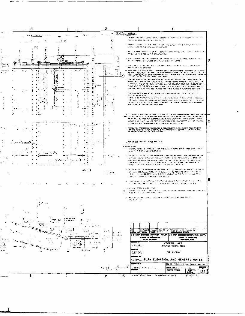
3 21
I -LESS -'EAS VE .NR, CONCRETE QC4PEESS fA<AES'A 5C'SHAIL. SE 3ý FS 'OR 4-. ((ORE 'F
2 AENE 'AAL NOTES A 2 AT3 AND A4 FRO "'E SAT
E' 4-5 (AL,,ET'L
APP., 2.52 s( "ESPA STRX~RJC ES
S ALL ,NFSORAEA SARFACES. ERCEET CASSTRIJCTIOAI ýNY5 5A. S- 0 AL ._
* FINISH AS NINOL.L'CAI tZ ASAPECFICATONS
4 L-ZO, YEIACTIONGALRE SDSTRENA JOINT QF OE-E "SAME: SLA*A'ýLAE
- IL IINS1 'ESI A S._AA SHA'A, HAA, 'S.A.F EDYES 'F "i N-' IS
THE S~ECTIONSO A~NTEHE WTONySLA~B. SCDIEý8 MGA52A" JOINTS SH0.ALLSSE
- AE IN5 'tTERNT'? EAs.G '. SECIN.FRIGA C. E BPOT R PACTES N THRE SA. B
I _______ ACE 9PI'('..AA SLAB YAEA REEl, PLACES AND RHEN P'LACED IN ALTERNAYE 5C1
A
olt 9 TAS CSRITA.CTR MAY AT HSI OTIRTIO AGE CCATINLERS AAA p. . ~~'TFOE 'x !L STILLING BASIN SLAAS.
THERE IS NC RETI I -II IOY ' I LE TCI RE OSEC A THIS 5 ,7'EEA A*"A JS}A T~lE'PEAS SAIAL BAF LACE IN ALENATE A-S I 'H A -- NMA 'TM.< '2- A'
* ~ ~ ~ ~ F -D~ , ~ TEr-, ALSA-LC-T C ANES CORATRACTIOR AOINS! ARE REQAIRED RERIAERN
A x LAINES, ANICES RAE ENDICFPAAAYSRALA
A 9 T ' SEOME A LERTICAL CA NEAR VFRYCA.. CAY IN ETHE FONATISONIMATERIALS. TYE CONRAS!MAY .55 ANY NIRC OF ISCAIAATO. AIRSI ECDB TRE CANTRACTFIG TFP'CEA NO fEt
W' *L-. BE MKAOE FOR )ERRARA SPAItIC EACAAATINGS '.IMIS SCORN IEAIE
O#ERETE A 11CE bA"ALST FACE OP THE EACAVAYION. CONA"TDAAC A. Lt bIE R('AC CA - - " REPACE AN' IERWENýAAE lTIH CONCRETE A' .I5 EAPENSE
p F4 AP(XACAYABPROTEIC` P90CEDUMRES &R'SPRWEWTS S LACEIMS EOJRCTPWR THE FITLER ALANKEY MATERIAL S THE PSRTIECTIAE OAIICRIFTE MR PRE`bUENTEC
I j IIA SPSECIFICAYII4 SECTION EXCAVATION
4, f ~ICS .. RO ERESD GENERAL NOTES SEE S-A7
GENERAL NOTES A TSA 34R FO TY0.'E OATLET *AORRS STRAICTARES CYALL APE..4'~ ~ y4 ~p5, IALSO R5 THE APILLAYRASTRUCTURES.
..... -XHA 7'. 5 LO'(A . PCES ARE RERISR.SLE PREFACES NO MORE TYAN HACID. H
A ,.~~A,,,o '5' ' -[B AER' E PERNIATES *.TAIN FEETP RA TE FRRNY FACE Lf TE AA,_. -N EST' ~ ~ ~ ~ ~ ~ - -A RAE7.
2ET.' ' AL_ .595 OAL SPLICEG ARE AT CS ,YBAC'SNO 'C.f*.
-. . . . ... . 0:,. -M'IET" AR. NF0'RCFM1ENT N ''EFSYFACE A..E RAGE
- 2 -~ ~ S RF'S#INS AA., REINFORCEMENT HAS BEEN I -E'LE 11-1AR0. By STHE .<-E ) CRSSFEYNS ADC,.YLNA, TETAIL' NS, OF M-A. -' REFSC . -' 'A'.
SA 87 71PRLN.CE LEO".- STA-NCE N -Au,', 'AR.' AT1,.EEA'N
ELA' NLCC',SART T- CANSTRL'C' -fC ISA.
AI .'-X'ENA IF'N'CAONG IN TIE RE'FAN'%GI SS -L--- E FT S "A BIF, 4A0f AH. I'NR AASC'EMS-5
AENEYA.. -,'EC C ',A (7 F-OP ThE -1KP .RN TTLJC"Auw_"2 S-GE'i'A SoT_'A-E SF R-.A 5'R C'..RES
AR*E.ON.OFCESSA...,ANTC2F -..A E..ZTASC.E.
APR.: ' 2A' 7'
A A xr
r- SAC o SS Ifhl afmSTi. SARI MS R y f
S L'.ETA RC C004PER LAKE
R R PIRRLERSPI LLWAY
RRAPLAN.,ELEVATION, AND *ENERAL NOTES
JSRRS S~~~~~AC 'P ItTRAI 5 A'A'
32 o"9- e''C 4
fft

5 I 4 3
L, 2DT
,L--2r --
• 4
i --
4l
1 0 1•-, 0
SPLN- SPILLWAY- LEFT HALF (RIGHT HALF OPPOSITE HAND)
4 31

3 2 1
7~- 7 1D F 1~- 1,
-ý -
V- 7 AL -1L;r.PP STEHA D
-Z., PVC, L.L TF

4 6ý7-
P7ý
cs 6

7 9 IC
iZ' ,R • " !L R 8
EL 5 53
PART SECTION THRU CHUTE SEE mllI" 1"I/s E
S~is
23 o0_
- C.- -W-O BCI A0 ER* 0 .a', A
90 ~ ~ O MIP SILLh -
It!9 BED ~w
-,A S LIE ...........
:?;:.I
•'4 0 0 2- .TEC IAVE CO E-L- IEL 35 IE
PART SECTION THRU CHUTEeB 34 T'2 S7A !Q 131
SC AL 3 16-1
-pR,202 R"'FE C U CAR"YO ~ .P5WTLACHUJTE SLAB AN APPROACH SLAB AOP _.O.A,*E$ a.o
LAP SPLICECOOPER LAKE
SPILL WAS C
1. 1 Aft A WEIR AND SLAB DETAILS I
'A CONCRETE AND0 REIN-FORCINGS
I IF Cýs, -,vu0 No 73'- ~ i

Kn
Kre / C
1' -DAMSITV>Kno
tt
.7 ., .7 . . . 7
-.. 4'.... X -
KrE
.. .. .. . . .. .. . .. .., . . . . . . . . . . . .
,\~~. ... ..." ~-/-',
.... .. . .. . .
. . ..... .....
.......K. .

"K LEGEND
- \2 2>
elf ES'CN VRAC
r to,,. * A PA
- ".~
LLS PEMP T
- P.'. aAPO"
N A:A OC H
4/ ~ ~K- NEYLANZVLZE
/ Kr'aý.
/ FAULT UPSTREAM FROM SPILLWAY
U RAC~ES-OhE
MBANKMENT -FILL.A" ANW' - TLET i,5KS
•[_.-q-mtq REGIONAL GEOLOGY
1'71
'"" ~ 'i227

2 3
'I ý,p 4 -4
i,-4880 6
11 14
*~~~~0O ~ ý, z"O<.000 0'

5 6 7 8 9
4 4,,-
loI
4'.4Ifl
7 a•'7•i"/,""''' i//
T. ". . * M r.
fi
, ,',,. ,4_
A -N
4+' . . . /l I
1/
-- ~0 ----- ' - -. 44W
A IN
2.
6 A - evf*'. f" -uQ*WTXC- IEWOZS L.oAC':. 1
-, 4",•. ,<*.,x., -,a.; 4' ~•,i.,•i.I•i'2 'CO•R L K
A..... .-' 'o,• A 'U Rc*NMEN

A 4 5 6
f�*., �NN�
-4--
M4 Z
-� -< . �W4 --
112
F _
KA- ... I ____
--.---.------ -___________ � '"%"A .bM W.
I �At� - --
4-I .-
� S - -t �-�'-�
-c -
-m -.--- '-C- -� --- 5--" I
K -'--A .- 'A -.
-�---------*-------�------ _____________________________________ -- - _________________ -
-- . A - WAS>
A -
- - - --.- 'rI> :. --- SO -
� 7
- A *r�
2 3 4 5 &

6 7 8 9 10
G
2 E
'- ~ I
-- .e - 2 ,,ign
EW9I DS,.T FORTLN 4. ,t
2'~g
CO1 ER AK
1-64, 17
a 1,A-olppk .1 oiuw6T.04 Wetcrr--AT C

4k . 0,5 f00 ~ 5
5z
-0'0S 4§¶-lo
4 4
MAP 0:ii.
,' .0 1a tnA0.",
2~ 375

7 9 10
31O& !J4
4 ,W,rN
a460
-:AL
C..
Lk- GELOI PROFILE C.-C
11 ',2V

.2 0 0
.kilo ý,W
A f6,Llz .. I~ A 2 A
~a~MtANAwl2~F -7 10N, - AI~
HA' F'Z52' '2 A: .E4E l--
91 P:41- 'S -, I -
UN- S,, -"TA
1; 1
"I T , I-'I -N W ý A;j,,10--- i--F I ii r ,"R ,
A ~ ~ ~ ~ ~ ~ ~ ~ ~ ~ fN A!0 'T%. ,AT"SRA AI 19
R ,C- 0 'I 1 22Iý VS~ pA INT N2- IN'~ :,`2'I~* i
A'tENT -S' N A1T :iOX
:ESC:PW 4N

67 8 9 10
G
F7
*~~~~CP- A A? *&A'K* ;Et
A.... SLL.. MV 5 'E A A jjS
- .. ,M~c.E #A 5, SA.AO
- ~IH ABUTMENTA -
v~~~.EOL GI VROFt.*AEc D.AtA -- '
jAAA.AA~~~~1 ":-A--AA-A',-'- -'7-

A. - -
- -t---- -' �,
- - '� *->t -- -- / -X
A - -A. A S-
<AU -S
j - - � 7��i A�A 2.� �

IA,
I
1 If
1 S 1 A •
- -' I L IUC
1 ~

4 £
[ - 4 \ - �2�- -
K
/
I--- ¶
I I I

I
1
- / .' .+x...-
� /�
,fl * S
I. __

I
FH
4KV -� -
K
/
I!
/

iT 7'
- <ii> NJ.'

I
II

4 --
I
I-
I I
7 C�f7N��o� .0;
A )
4 A AV -
-I

A - -� /
Iv -�- -
- p
777 <ft '{7177117i

A
T �O
IA fAN' -�- fo.r-�
r(�E: �Y
�ta. -C
A) F�, A-' ,AA � � '�OAAwf a
-. C '�

'. t
lo

+
t -
I ______________________________________________________________________________
�II.PV� ENc'UrE� 2zmc or
- y
4
- ft.-,-- WTA� �C I0�T :0
0flk0_r flr,:0
0' 0

T, v

p
* -
I.--
�'1 p /
-� �9&�,'L-
Iran- r c(r�M-Nc �,2,flcf

VH -
I I I I
I-
� I I I I

I I . .
-i

4 t
FI I
I I

I I I I 1 .t I
e..fl .�."

I ________________

I 77 t I

-r
-- V �-I V.-
1,- -/ A.
'A **. - -
- A-

4. - 4.-.4
v.4.> -
<44.' C- 4¾-- - 4. %4
4.4
I
-'-4¾ .. a a
j;: B 4.
.4 1
FN4, NFC4. NC CY¾"N S .$r, FNCINEEa Y49'C' �or WOn.<4 44. 4.4.. C" �
D�4�Et 8. JQ,.j4 -
4 .- 4 "1 4.'
44Sfl84 8' w4S¶Tt�. 'C 044 20844 C'.* C048IWC C
.. c � 'C4 '"A'. * . '.41 0'. .4fL-4.' 4'

A. Y.UZ M, w W t I- w",~.
"<TFAD<P' IUVM A< TD -_

ION
* * hA* .........

__

I
__ - �
7.
d d

�1
� N A - -�---� - ,�J7\AAA7N 2
- �N
I.
A
ii 1-

>'�� A.\ X*\
I -

. - . -I ,T
F II ,n
GIhS (17,CS HSTRC BRAN O~li
............. AE

-
-' .� "I
Ii
w�w

9--,
V... -
, i.4Z : N
- u' ,, ~1~
2.B C.BN NN

-------

=N
A.P1
4 '22/ ,
I,.
A . 1 VA. 'I', •CMW JOC tr3

L÷

*�J N$%EE�
A3�aN - �..-
4 0441 I
.-.. I1

4 ,.
t'S - -�
-A, 4
A - . kA- .
I - -XL? I -. .
& 5-
S - )1x
I,
N'
-S - - - -. � '1.4. iaJi�..�
A.
.2
k4
-J -
�<-Nf �
-- -A.--
A..
2 5

fK
G
* /•IF
'-17
t cm.0- •- FORT *OR-.
~ ~ S.X Hu- RIVER, TEXAS
- EMBANKMENT, SPILLWAY, AND OUTLET WORKS
)BRING LOCATION MAP I
1 , .
e 35

2 4 5 6
�/ � X � *� '�
4 *�-, S
- *Aj
'cv -�
- - -.
-*;. - � -A
-, -� -- -
-U4 S -,-�. .�
V 0
I. *-� -c -�
A
2 3 4 5 6

6, 7 8 9 .09
* \-
-~ !
'. N
*Sa -R -- Q TEXAS
SEMSANME,0T, SPILLWAY, ASND OUTLIET WORKS
PORING LOCATION MAP n.
--- -

2 3 4 5 6
14
-� '4
<K�Av��e
- �j�-< %
>� � <
K - 4
�- �
� - - -
� 54&Z4
>' �- j
- � � '�
-.
4
.,-� '�,
3� ..2�
I "0
-C
4
\,-' �
4
lx -
.9.,
9 a
�'
-�
,, e
2 3 4 5 ' 6

- - ---- -
-1", 7 'ý77 1
4 me7FAfk

....... .- .....
va -
M.1
... ... . ..
-- - - - ---- --- -- ---- ----- ---.

7 890
2 ~ ~ ... ... ...... ... ~-. G
... .. ...... .
. ... ,*2. EMBANKMENT. 22h 2.2
LOG OFBRIG
3S-101 , K16.A-03. 9 1, ew-0,0.Y 3 l"2, PLAT '-W

.... 1. ......
l..0~~~00it 171111=Z~. 0:
001014.0 A T,.0I .1.__ 1 1.21 __ =43=.
0.11-V.1Il,. *01..0a01.oo.1.0. 3 1 1.0
. .0
00.1.0.*l...1 Al 000004. .0?
00~ ~ ~ ~ ~ ~~~i V1. 101l"*0 .1.b10.
0 ~ ~~~~~~~~ at. alW0..I. 2::.10-
'1.0110.0C 3oo to22- :-ro- 00 o
1 .:~'
<0, __ C0 . ~ 00:0001 Ito0

56 7 9 10
7-C 4
-- 60.
_Z,2 .W -......
sC
j": . .... 7.. . . -"• - ] .- - - 4.. ......-- -" -4. -" 444,5
"'TI I
...... L O -7,ORINGS
540.50 4- ,ASllS OEV R so., 404... ... I4S444.-.|, .1I .S-.4 5-0i44A000.S- 4,6'4I
AI
4..•-I
-. ~ ~ ~ A IO4 '.4 2422.
1100.0404~~~~- = : 11.4 1D. 4.0440-T H4.4. 454.
F. -COO.40.LA .464444~~~UL"U RIER TEXAS454..44. .4..
1414. 44l440. ~ .---- '------.
4.440404444.04 4. 4*54*.*5. 4411 EMBANKME 6NT 45
LOG OF BORING
NOTE IIA-II381SAIIII REVER DRILLED ........ 64 3S lO A 113 -l , S 14, 1500 -1 ,3 -1,6 -t
* 4040.~ -.
- - - -- - - - - - - - -. 4 .
-''4.~~~~~~~ 744
*4 *1 2 ____
f_ _ eo-ww "rLA

2 3 a 6
c-s, -. --
Pt - -- - ... -".2 - -.
20 �2 .s224 � 4
I�454
� *.
-4'.. �41
2r.
iF 1 � �A 424.2
�- 42._____ 4442142 I *447742*�
.22.54,7 142'4'4...*.54 4O42!2-744744"421 �
,j 4244 '.42.. 1 .
- .5*4... *4444 2742
4424. 4475642.4 3�42�4�3.
:6.2 - 42'4 4542- 45,. 244.21 54477. 4*4 .4*. 24�444442� I- 14.544
___ : .444454"fl.. 12.. m.i4. '<"K,..
44 4.444,4
- - L
.. 4....44. .2457. 7.1425
1444 4.54 45444 1�s 41*fl44I4�. 54'4 '527 4 27
- ..�s -
42�'' --- 4 I 4.12.244 .6.2
7452442 .255524
554414*S 754 44 -4-- I 5tt4.S=
7444422455 *"��5'5�4� '� 24754 145 524,45 2455
frm ,. 7ra.ns. n4t542 4CC 4 4
F � ,. ... -. -4�
4ts.4 p . � - _______ ____
____ __ __ ___ _____
________ .�Ait '�'� __________
.....................�..........[ 4.24242.;
.2422.4405 4 224:143 � -- 47 17� 744.444 4474545542,... I� 42442
4 40.2 C 14. 14421444
52.57.2577.44741 4 - 447
�,224�445554� ��:..444742.414 r .24.4 4".
2.47.44' 424242.4577 .24,54�#.244.. jfl � 42425 4447447 .2454, 61244,a .25i45414..44.2*4. ��7427 175.2455411- .55 .44 45.55442 '442114 42444**41574.444744� 1144214454, .24�4 4.4.. 42.2442.247 .5477.442�445444. 5544.2.447474 � 4244,46447442.4. 542'?
44777.2.7. 41 44*7447 .2454 42
74�4 5444 45544. 4 44*7417 .24472�424t. j 47L,420'55.544.l4.4444547245.4j.
47141 4
A
2 3 4 5 6

6 7 8
li~z
~0.tt ~S
L. .S. .... 3r -_ • • - • • .-
',---- r. . .. ..Z . -l •:; -.U fl •-3 - -,- ... . . -.. •. . . G-.-- . . .
-- .- .o .. 3 r -'2- _,_o•
tv-Z3-
S- -333.. I -. ,
•,--•.--. •?•3.3 - ', ,_ ,_. ... _
E
~~~~~~~~~ .. .,• •:•-rn=..,-r•
3.. ... 303-..... -3:-" .1 3L•..3. ...*, 333.3.
"-33.... ".""-,..-:L • -. x *i : '
3..3..... L ...... ""330, ;3
in.
c,- S ..
F= ýE
S~E MBANK ME NT
, r, ,LOGS OF eORINGS- - 3S -120 THROUGH 3- -126
6. . -

S 3 4 5 6
40*0 - -4
i I _"
-. .0........ ...0.......-'--
. 9 ~ 0 * ~ ~ ~ _ _ _ ~ ~ ~~ . 0~ * * ~ 9.
o.....• -" 9,.. .0099,-" . .31-
-'--" -
94......, 9 , * _,
•A.9.o.9o *019y.,1,09S. ..... .' i !
. ....... .4 ......
-- o~y~o~.91*,'9.
1. 10900,941.0 m m mm m71

6 o6 3 0
iG--• . . . . -- ,. "3 -- •,•1 •.-•... ....
a.. rn no a e. .. . ... . . ... t* ... .S.33 ._ ...- . . . .• _ " . .-- .'; , . . . . • . . . ."
-.... -e n=•"-•'... '"- -.... ..r....
•,-_ •, -.........'
0....
................... ..... ..
AA* .
so..L ......
VV-. -T T 1-, *-1"
to .3. *.-t*COOPER LAKE
-------- VS L3 6A-12 TH O G 6A 13
all6 8 ~ .O A.Jf~?JA ~ jV0OV. £ ~ 0
LI44I

2 4 5 6
, ... #,. -IAP. -
.. n .
24 1 Ito"......... I . •' .... . .. 7__ -[: .. . 30'. " '•' . ,_ _ , -. , • " '
to.oo; .6 [
0230 -o9 -
m , , , -- A
S- ,- • •-- --.- ..-..--. 0"=: .' . ;. "L.. ....
t: LIM t.ow
.•:- ... , t I.. ,. -__-A 2. 3 , •-'""': • ... . ..÷~ 'S. . .. . .,- . : - - -, .- 2-r....o_
Ow', -o' I
4 w, o ooý ,
* ,

7 8 9 10
-:l -ý - L
xie-F
F
ba.. '4
, -- 48
z.-.-. c,.-.. flCOOPE LAKE,
-UPW hII, 4 T EXA
-------- 6 -13 .I..5 6A-13
---------------w -,--

=M W .. ........
-. __ __ .- -.- -7**A
&r2 A ' -_____
1 A. ISA A 6A4AAAALIZ:.
Eo
-alit6
3a6.A666AJ.AAAAA=7* zn*-f*~3AA36.
.6.3. - - ~~~am AAAa3.A AA

~~~~~~~. l.S r , t . *. .1
r e~uE
S. '5.IP USOT FPco""5.IE -- SI-
1L SMA MO ,*Mr- -et

9ý~ 9
.Wt
* IF-0- 4.. -f-.
A
09. 5, 90- 6, 9 12 .
Alp~~ F
:Z:s.:2.A-1.1 90-
595,0 .5
iLzy _t -,
Y~~~fl~~*1.~~~:7 Z:1t,:1L;4149~~A9_
It-"

68 71
. . .. .
-" ~' 'fl~'.CV
IE
IE-
L XS 0iF 8 R I NG ------ S4318 H C !H 8 4 -4

2 5 4 6
�7662�26 �L6.66�66 -
_____ - -I 2, � -�r - __ 66666 6766 J � - - - 7rra. 6266..p666 - 666 6676666666 "2�'666W6W666666,w;r�� 066266 .* 6666666666662 -.666�.6 - .�66-�--- �±6.1W... 6 . � 2�'�*67660. 70 2�� -- �--.�------- 2 - --
k � 6�* - .666�6 � - -- 666 - 66 666 776 .6 -. -.
- -. 7; x - - -- _____ C.-.*-6. 6 -:z..... '62666663 ,...� 66262
0<6 266 66 6 6 66 1- 7166 6,.:6.6.:6,6.. 7 6 :67 7' 4* . 7'..
22
6666.66666666.6.6.6.., 2
* . 66666. 66666.666626 66 *7:6!66676 6667. 66667666 *6.6666.7462.6.66..
66 66 7 266 16667. --
.- 666..6.6.66.4: , 6.66.6666666666� . F-666.0 6* -. 666666 6:66 I 6666666.6��666 66666 666666 6261�.6 61 * 666 *6.66766 -� .. n .64 r66466..:666, .6766666661.66.0 66 6 66 4 666766666,666'76676666642.$-666.66666 :i. 626766 6666667666 .6 566.6666.7 � I .. �-.6.666:66. *6.766.6:. .66 6666 -. 766666:6:: 6 '6.- 66.-i''6 6666. .666:2 .6:6666 626 , - 666.6 1. 667.666�. 7666 666 6766 ..2rn-
'706.67.7 66 66� 6666666666466.66 - IAJk-76666666 666
6647666666.66 6.7 .. 66667662. 761.61 6667 62- 9e 4666667 6676 64 66767666.66666.�....
6666666.6666 *� {j� 661.6* .6666. ' r666666666763666616.6.6
�626
6666666666.
666666. ��6666.' _ �> 6666666646666666666666.616. �66666d 666666 .66 .- * 766676266.6664426766666.66,2 6 2.6 66:.6 I6766666. 6�666666 66 666666 6666666
6666 66 44.6'. 66666 6766 ii-'1.66.6 4i� -Jr��.2J
- 3 : �*5 366. 6666666. �666.67 66�666664 66 67.0'.
�±�666.6666664.6666666,., . j . 266'W6666266666 - 66.6667666666666.66 6 7 6� 6666667 76666667.6. 6 6566::. 66 666 6666. 6666'*'' r -.6 '6666666666677676.66 66.5 __I -- �-1' 5�6�.. . 66.666 6
1.7r� 7 666-.. 6� -� - V 666 2
6 6 V� -66�2 �66* 0 6 , ..6666666,66662766667666 6. �66r'2
2". - -77 66666 -�666 �666667 7666,6666 2 666266466666666666. 6667�67664. 6.66666666466503/�6,-- -6* 66666666664
674.- 6 6:7664666661.66 . 1 7667.622.7977762.66.7. - - 6666766666666766. -. ,6666:66.62662.26..6662�6.7.66 66661.46.76646.76 C '-'i 6665666.7.
6261.766 - 666646666 6676.' 66.21,3�2.7l66.6- 666666666 6� - -- .� 666666767666666666662666666662.7666 3366 .6q .7677.6 1 6666666766,62766626.666766666 666667. 666664661.61.6666266 I 6766626,6.66666.6.1.66 6676.76 66664 .6 261 666666 66676,. 666 66 26666166. .6:66666,66.666. 6666266762666.2 776 76 66 666 .61. 666 66
16 .. 6666.7664 66.667
666 666 .6 66 6666 7.66 �.. 64.:666�616762 66.
6.66 6666666 664- 356o 661.26666.6.6666766666661.66. 266.6 . 66626616 6666666666' 666666666.6. *�27 2622 66666 666 .6.,676.666> 6666 2266666666624
/62667 �666666.6 6.6
3 '�.2 -j1. .666,6�2 4667466672667666. 5 6666.6,667666626 2
90. 6.46�.�666 �6 � 666666266666666.66�l62i04664��666466 6 2 6.626. 67666.66666 666666666� 6666666666 -� 66766.6.66666266.507264.6666,6667. 6666 6 , �- 26666.6666666666.
50.7- �666fl�.50666667.
6 6 62 � �2.6.7 6667.6
66666. �66676.7 6666 6� ,9666.6SC6 3jt66;7*2wl - 6?666 21.66676666666 2 .6666276262 7621766. 622 26667.6.6. 6666, 2 62�26 622666.26622,666:667.6666(66.66.766 26 2775 2:6.6.6.6:6622262..6666666.666 . 6162 6 j- � 2-66662.6.- �666666 6 . -36.666666.66 06666666, 26 1 h
6. 26 626
.66 3666 .76267266666 6,66 62'. 261
66 16 6 �il3�6266,66766666.666.26 66666276677666'2.250. 622
3 4 5 6

67 9 90
-~ G
7r=;" .9
7 C
114109W2
moor t-. n'
08- - I-- - - - - - - -
L1 -- 26~~o. otEOL VL, 4

C 4 5 £
* -a�n.-w {r��NNcW -N. _____
-J -C-
____________________ * 'I"
A
'C-U '
i.jt -i-iA
It - >C
V
Sna
A
* -N. �I'NNhN*'-��' -N, 3. -$---�
"¼
IN4
N *NIN.N 0
3NNo wN
BNN
VjNN
S � -N'
3 4 6

7 a 9 -
G
OMLLN LM
A
2' E.2'
L-1 31
' -. -- z
t- " 2 g '"
ii"IF M*II,ýOT*0
22.2... *..26',
66 R LAKE.
LOG OF BOIG
NO'E DOM 2 POWEP DRILLED ----- IBM - 1, DSM-3
-c ' ----- 0 - -- 01
6 ~8 Acerw-01Y -NAL ;Plw¶c wwt 9 Al&-4

140~~~~~ 1.I 11,1 1* nCI 0 I
l24 4144. 1 1I L~ I
0~~~ It. 'l I,4 it*l
B4II ~ ~ ~ ~ ~ ~ ~ t 40 -Olli CII- -01 0o
It ,10 iu.1 ~ I
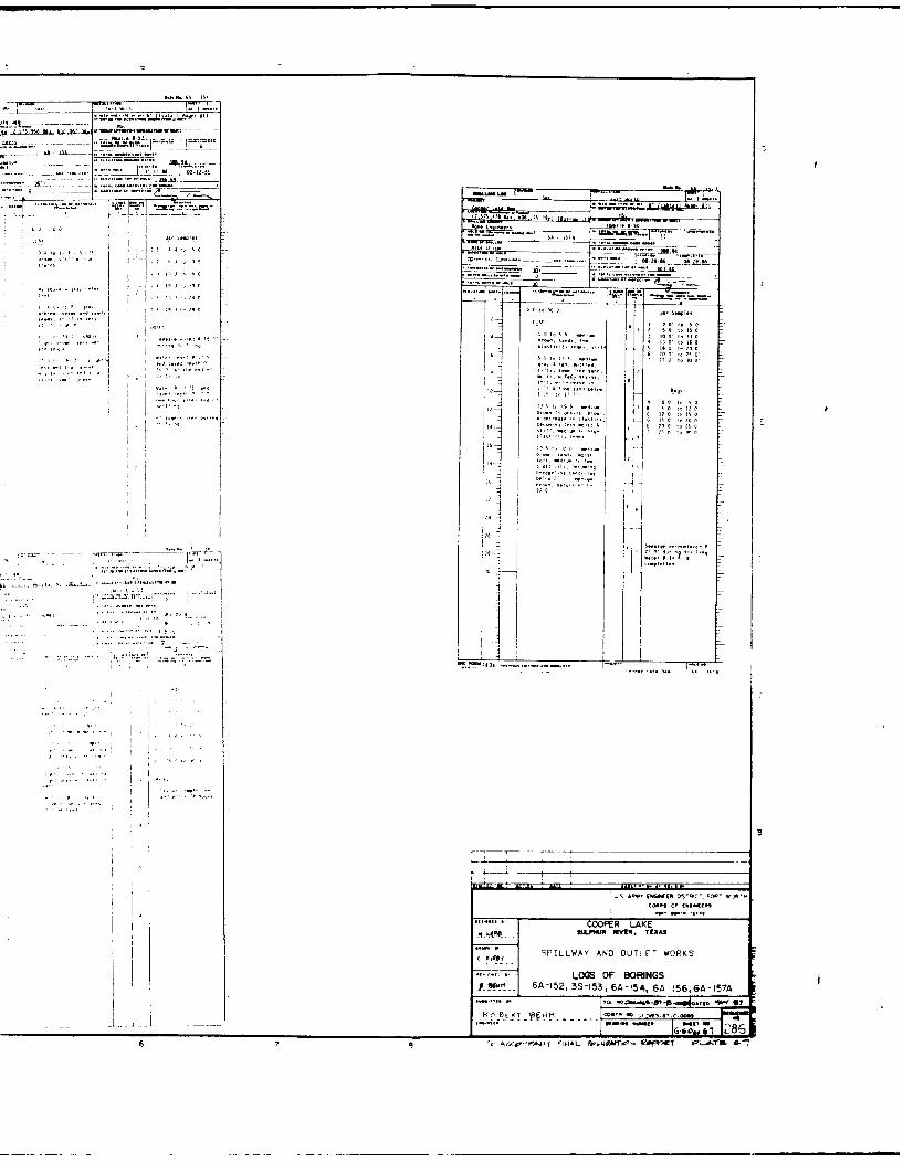
•.. .........
1' 2
.. °................. .,
.COOPE LAKE
* I -iF 555*7 *0 011
-.. Jl j * . :'. "7" 4.5 ,50 0.,. . ''5... ... .. ... ... - ;4
I 1*5 A .,o s -_
-.. .., 1,q 554450*5.... 51*
5 sLmHuRIVER, TEXA1S
r• SPILLWAY AND OUTLET WORKS
P 5 GA-152, 3S-153, 6A-154, 6A -156,6A-157A
- o 47
!Zi
61. *1 A
605 555- '2 F 5W.P , kAIW 5 5 %p.55 A'7

-' 6*2�s�La
L IS- ��fIAa. -�
a -., , - -
�
:1 I' 66.
I � �.
�
� I 'I
6-I =
'66
I
�1
______�
�Li__
I- a
96
. ,. '.94,
-96'... -
6
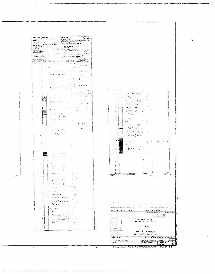
Im..
.1. 7 .
3 S4C-2O7.i3S4C-208
IJ~n --- --- 7... .....
* ~ ~ ~~~ ist7C6'tO~

-� b��9
I ______
rn� t' Aa. c��aflz. Wfl
JO
-- t. U.
-. r
. I,.. .__ [
S. . I,,
II
'7,
4 5
L

tup"~ PH5,TEA
LWA ~ 45,54 5$d 5. - S
C 8 -~~~ ~ LOG 0OF4A~''1 BL4~L 4S

'"-,WPM
'B:44
t-wt-
t- 1 5
'C.'.'

~n~.i~z - .~ n~'t.- ---- ------
7 7
LL
I . ~ .2QP5P LAKE
LOSOF BORINGS
e ~f, ^l''ýt¶ -AMY -N4..- 4
l'J'JVtflO' PGfl A #t .50

- - U., �2t
V
I -�
I:
I *1
ii
� I4� I
� . I h
3 4 5

.41
LOG OF BORINGS

W, -Off Aei.
....sw~ .... .....
-,o~

COO-'Ek LAKE
P" Y P. 'EA
LOGS OF BORINGS354(U215,3S4C-21E,SA4C -217-,BAC-2I8'y.
*tme ýýT e, 2~f

�-r�&i i� -'�flrz ��1izz�tt. OILLG L� ______ ___________ L -Li- L�
-, an-,
in. a. Th2k2.. tr.
* "l,.,.�, Lj
Fl
iii. I
__________ __ __I
4 5 6

C7 '
,fl'taa..F--- LAKE.~~fl c-a*. ~ ~ ~ ~ ~ ~ ~ ~ ~ ~ UPP MV"a SAas.. I .A l)-n ~,w a TEXAS
EMAKMN
__LOGS___ OFHFM---------*- LA4 lkr'4C-2 ,B 4 -2218ACA2rz
-I IALla'A'..A
-14T,1 3.Q A j WPo - g P

. .f .... ... -t
rUULL~~ .- .. . ~. .1 ..s. ..-.
-- -, 13 1
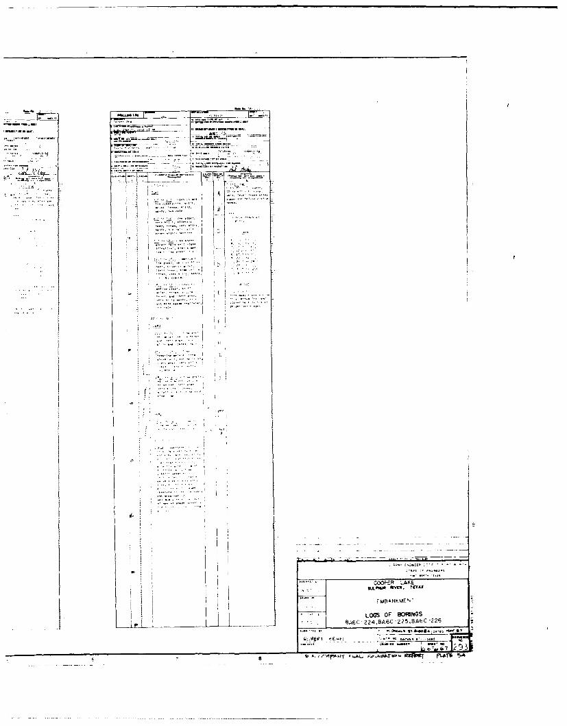
7 L
7
1 B1