Elcometer 456 Coating Thickness Gauge - Cole-Parmer · Coating Thickness Gauge Top Models ... No...
67
English Elcometer 456 3 Coating Thickness Gauge Top Models Operating Instructions
-
Upload
truongtuyen -
Category
Documents
-
view
234 -
download
1
Transcript of Elcometer 456 Coating Thickness Gauge - Cole-Parmer · Coating Thickness Gauge Top Models ... No...

Eng
lish
ge
s
Op_456_3_English.book Page -1 Thursday, May 24, 2007 9:18 PM
Elcometer 4563
Coating Thickness Gau
Top Models
Operating Instruction

Eng
lish
models:
Equipmen g Patents:FNF UK Pa 86522F1 2 UK Pa 6,762,603F1 2 Germa
This 93/68/EEC.
® and Bl ometer Instruments Ltd.
All other tra
© CopyrightAll rights res ibed, stored (in a retrieval system orotherwise) o echanical, magnetic, optical, manualor otherwiseA copy of th lcometer.com/downloads.
Doc.No. TMA-0424 Issue 02Text with Cover No: 20243
Op_456_3_English.book Page 0 Thursday, May 24, 2007 9:18 PM
R
These instructions apply to the following Elcometer 4563
Ferrous (F), Non-Ferrous (NF) and Dual Ferrous/Non-Ferrous (FNF)
t described in these instructions is covered by the followintent No: GB2306009B FNF US Patent No: 58tent No: 2367135B F1 2 US Patent No. USn Patent Pending
product meets the emc directive 89/336/EEC, amended 92/31/EEC and
and are registered trademarks of Elcometer Instruments Ltd.
uetooth® are trademarks owned by Bluetooth SIG Inc and licensed to Elc
demarks acknowledged.
Elcometer Instruments Ltd. 2004-2007.erved. No part of this Document may be reproduced, transmitted, transcrr translated into any language, in any form or by any means (electronic, m) without the prior written permission of Elcometer Instruments Ltd.is Instruction Manual is available for download on our Website via www.e

R
1
Page. . . . . . . . . . . . . . . . . . . . . . . . 4. . . . . . . . . . . . . . . . . . . . . . . . 5. . . . . . . . . . . . . . . . . . . . . . . . 5. . . . . . . . . . . . . . . . . . . . . . . . 6. . . . . . . . . . . . . . . . . . . . . . . . 6. . . . . . . . . . . . . . . . . . . . . . . . 6. . . . . . . . . . . . . . . . . . . . . . . . 7. . . . . . . . . . . . . . . . . . . . . . . . 7. . . . . . . . . . . . . . . . . . . . . . . . 7. . . . . . . . . . . . . . . . . . . . . . . . 8. . . . . . . . . . . . . . . . . . . . . . . . 9. . . . . . . . . . . . . . . . . . . . . . . . 9. . . . . . . . . . . . . . . . . . . . . . . 10. . . . . . . . . . . . . . . . . . . . . . . 10. . . . . . . . . . . . . . . . . . . . . . . 11. . . . . . . . . . . . . . . . . . . . . . . 12. . . . . . . . . . . . . . . . . . . . . . . 12. . . . . . . . . . . . . . . . . . . . . . . 12. . . . . . . . . . . . . . . . . . . . . . . 13
Op_456_3_English.book Page 1 Thursday, May 24, 2007 9:18 PM
CONTENTS
Section1 About your gauge . . . . . . . . . . . . . . . . . . . . . . . . . . . . . . . . . . . . . . . 1.1 Features . . . . . . . . . . . . . . . . . . . . . . . . . . . . . . . . . . . . . . . . . . . . . . . . 1.2 Standards . . . . . . . . . . . . . . . . . . . . . . . . . . . . . . . . . . . . . . . . . . . . . . . 1.3 What this box contains . . . . . . . . . . . . . . . . . . . . . . . . . . . . . . . . . . . . . 1.4 Conventions in these instructions . . . . . . . . . . . . . . . . . . . . . . . . . . . . 1.5 Quick-start . . . . . . . . . . . . . . . . . . . . . . . . . . . . . . . . . . . . . . . . . . . . . . 2 Getting started . . . . . . . . . . . . . . . . . . . . . . . . . . . . . . . . . . . . . . . . . . 2.1 Fitting the batteries . . . . . . . . . . . . . . . . . . . . . . . . . . . . . . . . . . . . . . . 2.2 Battery condition. . . . . . . . . . . . . . . . . . . . . . . . . . . . . . . . . . . . . . . . . . 2.3 Fitting probes . . . . . . . . . . . . . . . . . . . . . . . . . . . . . . . . . . . . . . . . . . . . 2.4 The controls . . . . . . . . . . . . . . . . . . . . . . . . . . . . . . . . . . . . . . . . . . . . . 2.5 Switching the gauge on . . . . . . . . . . . . . . . . . . . . . . . . . . . . . . . . . . . . 2.6 Switching the gauge off . . . . . . . . . . . . . . . . . . . . . . . . . . . . . . . . . . . . 2.7 The screen . . . . . . . . . . . . . . . . . . . . . . . . . . . . . . . . . . . . . . . . . . . . . . 2.8 Selecting a language . . . . . . . . . . . . . . . . . . . . . . . . . . . . . . . . . . . . . . 2.9 Interfaces . . . . . . . . . . . . . . . . . . . . . . . . . . . . . . . . . . . . . . . . . . . . . . . 3 Taking a reading . . . . . . . . . . . . . . . . . . . . . . . . . . . . . . . . . . . . . . . . 3.1 Before you start . . . . . . . . . . . . . . . . . . . . . . . . . . . . . . . . . . . . . . . . . . 3.2 Procedure . . . . . . . . . . . . . . . . . . . . . . . . . . . . . . . . . . . . . . . . . . . . . .

. . . . . . . . . . . . . . . . . . . . . . . 13
. . . . . . . . . . . . . . . . . . . . . . . 13
. . . . . . . . . . . . . . . . . . . . . . . 14
. . . . . . . . . . . . . . . . . . . . . . . 15
. . . . . . . . . . . . . . . . . . . . . . . 18
. . . . . . . . . . . . . . . . . . . . . . . 23
. . . . . . . . . . . . . . . . . . . . . . . 23
. . . . . . . . . . . . . . . . . . . . . . . 25
. . . . . . . . . . . . . . . . . . . . . . . 26
. . . . . . . . . . . . . . . . . . . . . . . 27
. . . . . . . . . . . . . . . . . . . . . . . 31
. . . . . . . . . . . . . . . . . . . . . . . 32
. . . . . . . . . . . . . . . . . . . . . . . 32
. . . . . . . . . . . . . . . . . . . . . . . 32
. . . . . . . . . . . . . . . . . . . . . . . 33
. . . . . . . . . . . . . . . . . . . . . . . 33
. . . . . . . . . . . . . . . . . . . . . . . 33
. . . . . . . . . . . . . . . . . . . . . . . 34
. . . . . . . . . . . . . . . . . . . . . . . 34
. . . . . . . . . . . . . . . . . . . . . . . 38
. . . . . . . . . . . . . . . . . . . . . . . 38
. . . . . . . . . . . . . . . . . . . . . . . 39
. . . . . . . . . . . . . . . . . . . . . . . 40
Op_456_3_English.book Page 2 Thursday, May 24, 2007 9:18 PM
R
2
4 The reading screen and menus . . . . . . . . . . . . . . . . . . . . . . . . . . . . 4.1 Reading screen . . . . . . . . . . . . . . . . . . . . . . . . . . . . . . . . . . . . . . . . . . 4.2 Main MENU . . . . . . . . . . . . . . . . . . . . . . . . . . . . . . . . . . . . . . . . . . . . . 4.3 Main MENU - Extended menu off . . . . . . . . . . . . . . . . . . . . . . . . . . . . 4.4 Main MENU - Extended menu on . . . . . . . . . . . . . . . . . . . . . . . . . . . . 5 Calibration adjustment . . . . . . . . . . . . . . . . . . . . . . . . . . . . . . . . . . . 5.1 Calibration method . . . . . . . . . . . . . . . . . . . . . . . . . . . . . . . . . . . . . . . . 5.2 Preset calibration methods . . . . . . . . . . . . . . . . . . . . . . . . . . . . . . . . . 5.3 Calibration foils and standards . . . . . . . . . . . . . . . . . . . . . . . . . . . . . . . 5.4 Calibration adjustment procedure . . . . . . . . . . . . . . . . . . . . . . . . . . . . 6 Statistics . . . . . . . . . . . . . . . . . . . . . . . . . . . . . . . . . . . . . . . . . . . . . . . 6.1 Enlarge stats . . . . . . . . . . . . . . . . . . . . . . . . . . . . . . . . . . . . . . . . . . . . 6.2 Stats on LCD . . . . . . . . . . . . . . . . . . . . . . . . . . . . . . . . . . . . . . . . . . . . 6.3 Display . . . . . . . . . . . . . . . . . . . . . . . . . . . . . . . . . . . . . . . . . . . . . . . . . 6.4 Clear stats . . . . . . . . . . . . . . . . . . . . . . . . . . . . . . . . . . . . . . . . . . . . . . 6.5 Select stats . . . . . . . . . . . . . . . . . . . . . . . . . . . . . . . . . . . . . . . . . . . . . 7 Batching . . . . . . . . . . . . . . . . . . . . . . . . . . . . . . . . . . . . . . . . . . . . . . . 7.1 Exit batching . . . . . . . . . . . . . . . . . . . . . . . . . . . . . . . . . . . . . . . . . . . . 7.2 Open new batch . . . . . . . . . . . . . . . . . . . . . . . . . . . . . . . . . . . . . . . . . . 7.3 Open existing batch . . . . . . . . . . . . . . . . . . . . . . . . . . . . . . . . . . . . . . . 7.4 Review batches . . . . . . . . . . . . . . . . . . . . . . . . . . . . . . . . . . . . . . . . . . 7.5 Set limits . . . . . . . . . . . . . . . . . . . . . . . . . . . . . . . . . . . . . . . . . . . . . . . 7.6 Free memory . . . . . . . . . . . . . . . . . . . . . . . . . . . . . . . . . . . . . . . . . . . .

R
3
. . . . . . . . . . . . . . . . . . . . . . . 40
. . . . . . . . . . . . . . . . . . . . . . . 40
. . . . . . . . . . . . . . . . . . . . . . . 41
. . . . . . . . . . . . . . . . . . . . . . . 42
. . . . . . . . . . . . . . . . . . . . . . . 45
. . . . . . . . . . . . . . . . . . . . . . . 45
. . . . . . . . . . . . . . . . . . . . . . . 45
. . . . . . . . . . . . . . . . . . . . . . . 46
. . . . . . . . . . . . . . . . . . . . . . . 47
. . . . . . . . . . . . . . . . . . . . . . . 48
. . . . . . . . . . . . . . . . . . . . . . . 51
. . . . . . . . . . . . . . . . . . . . . . . 51
. . . . . . . . . . . . . . . . . . . . . . . 52
. . . . . . . . . . . . . . . . . . . . . . . 53
. . . . . . . . . . . . . . . . . . . . . . . 60
. . . . . . . . . . . . . . . . . . . . . . . 62
Op_456_3_English.book Page 3 Thursday, May 24, 2007 9:18 PM
8 Transferring readings to a computer . . . . . . . . . . . . . . . . . . . . . . . . 8.1 Transferring Using a Cable . . . . . . . . . . . . . . . . . . . . . . . . . . . . . . . . . 8.2 Transferring Using a Bluetooth® connection . . . . . . . . . . . . . . . . . . . . 9 Probes . . . . . . . . . . . . . . . . . . . . . . . . . . . . . . . . . . . . . . . . . . . . . . . . . 10 Personalised welcome screen . . . . . . . . . . . . . . . . . . . . . . . . . . . . . 11 Storage and transit . . . . . . . . . . . . . . . . . . . . . . . . . . . . . . . . . . . . . . 12 Maintenance . . . . . . . . . . . . . . . . . . . . . . . . . . . . . . . . . . . . . . . . . . . . 13 Statistics terminology . . . . . . . . . . . . . . . . . . . . . . . . . . . . . . . . . . . . 14 Technical data . . . . . . . . . . . . . . . . . . . . . . . . . . . . . . . . . . . . . . . . . . 15 Accessories . . . . . . . . . . . . . . . . . . . . . . . . . . . . . . . . . . . . . . . . . . . . 16 Related equipment . . . . . . . . . . . . . . . . . . . . . . . . . . . . . . . . . . . . . . . 17 Fitting the wrist harness . . . . . . . . . . . . . . . . . . . . . . . . . . . . . . . . . . 18 Probe measurement performance . . . . . . . . . . . . . . . . . . . . . . . . . . 19 Probe capabilities . . . . . . . . . . . . . . . . . . . . . . . . . . . . . . . . . . . . . . . 20 Error messages . . . . . . . . . . . . . . . . . . . . . . . . . . . . . . . . . . . . . . . . .
21 Index . . . . . . . . . . . . . . . . . . . . . . . . . . . . . . . . . . . . . . . . . . . . . . . . . .

able inBasic,. This
s thethe
p. gauge-to-useaphicales the
s suchurationbration
ble either with a built-in integralate probe version. A wide rangeble to suit requirements - see probes may be standard, Integral Probes (PINIP™), andparately.
R
Figure 1. Elcometer 4563
Coating Thickness Gauge
Op_456_3_English.book Page 4 Thursday, May 24, 2007 9:18 PM
R
4
Thank you for your purchase of this Elcometer 4563
Coating Thickness Gauge. Welcome to Elcometer.Elcometer are world leaders in the design,manufacture and supply of coatings inspectionequipment. Our products cover all aspects ofcoating inspection, from development throughapplication to post application inspection.The Elcometer 4563 Coating Thickness Gauge is aworld beating product. With the purchase of thisgauge you now have access to the worldwideservice and support network of Elcometer. Formore information visit our website atwww.elcometer.com.
1 ABOUT YOUR GAUGE
The Elcometer 4563 Coating Thickness Gauge is ahandheld gauge for fast and accuratemeasurement of the thickness of coatings on metalsubstrates.
The gauge is availthree versions; Standard and Topmanual describeoperation of Elcometer 4563 ToAll versions of thefeature an easymenu driven grinterface which guiduser through taskas gauge configand caliadjustment.
The gauge is availaprobe or as a separof probes is availapage 42. Separateminiature or Plug inmust be ordered se

R
5
can be used in accordance withal and International Standards:
Non-Ferrous (NF)BS 5411 (3)BS 3900 (C5) BS 5599ISO 2360ISO 2808DIN 50984ASTM D 1400ASTM B 244
Op_456_3_English.book Page 5 Thursday, May 24, 2007 9:18 PM
1.1 FEATURES• A range of smooth and rough surface
calibration adjustments.• Menu driven backlit graphical user interface.• Interchangeable probes (separate versions
only).• Statistics.• Bluetooth® interface.• RS232 interface.• High/low limits.• Memory of up to 50 000 readings in up to 999
batches.• Clock/alarm.• Date and time stamping.
1.2 STANDARDSThe Elcometer 4563
the following Nation
Ferrous (F)BS 5411 (11)BS 3900 (C5)ISO 2178ISO 2808BS EN ISO 1461DIN 50981ASTM B 499ASTM D1186ISO 19840SSPC-PA2 (2004)

re the gauge and start taking
see page 7see page 8see page 9
e: see page 11ding: see page 12n: see page 23onfigured and ready to use.e benefits of your newease take some time to readstructions. Do not hesitate to or your Elcometer supplier ifstions.
parate probes only
Op_456_3_English.book Page 6 Thursday, May 24, 2007 9:18 PM
R
6
1.3 WHAT THIS BOX CONTAINS• Elcometer 4563 Gauge with integral probe, or
Elcometer 4563 Gauge and separate probe(probe must be ordered separately)
• Calibration foils• Gauge carrying pouch• Wrist harness• Batteries• CD containing data collection software• Operating instructions
1.4 CONVENTIONS IN THESE INSTRUCTIONSThe Elcometer 4563 is controlled using a simplemenu structure which helps you get the most fromyour gauge - see page 18.As an example, the LANGUAGES option which is inSETUP from the MAIN MENU would be shown inthese instructions asMENU/SETUP/LANGUAGES.These instructions include images of Elcometer4563 screens with units set to microns (µm). Similarscreens will be seen when the gauge is set to otherunits such as mils or inches.
1.5 QUICK-STARTTo quickly configureadings:1. Fit batteries:2. Fit probea:3. Switch on:4. Select languag5. Try taking a rea6. Adjust calibratioThe gauge is now cTo maximise thElcometer 4563, plthese Operating Incontact Elcometeryou have any que
a. Gauges with se
R
7
DITION.
condition/action required
00%
6%, replacement ended.
3%, replacement required.
auge beeps every 10 seconds bol flashes - immediate ent required.
eeps, gauge switches off ically.
Op_456_3_English.book Page 7 Thursday, May 24, 2007 9:18 PM
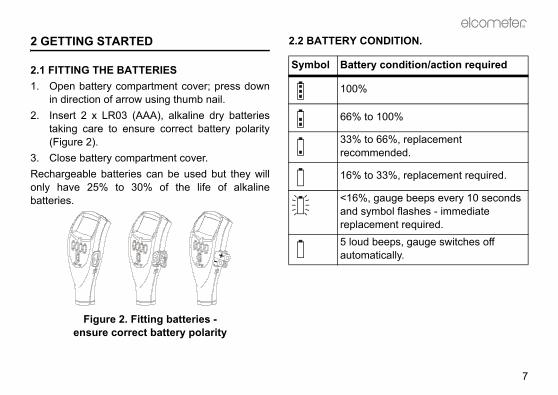
2 GETTING STARTED
2.1 FITTING THE BATTERIES1. Open battery compartment cover; press down
in direction of arrow using thumb nail.2. Insert 2 x LR03 (AAA), alkaline dry batteries
taking care to ensure correct battery polarity(Figure 2).
3. Close battery compartment cover.Rechargeable batteries can be used but they willonly have 25% to 30% of the life of alkalinebatteries.
Figure 2. Fitting batteries -ensure correct battery polarity
2.2 BATTERY CON
Symbol Battery
100%
66% to 1
33% to 6recomm
16% to 3
<16%, gand symreplacem5 loud bautomat

betion and pulle gauge. Thelock and the
ntil theTakings theobe byg ringse, or
Op_456_3_English.book Page 8 Thursday, May 24, 2007 9:18 PM
R
8
2.3 FITTING PROBES(separate versions only)
To ensure correct transfer of data from theprobe and detection of the new probe, thegauge must be switched off when
separate probes are fitted.A probe must be calibrated once it has beenfitted - see “Calibration adjustment” on page 23.
To fit the probeAlign connector keyway andpush in direction shown. Theconnector locks automatically.Note: The design of the probeconnector allows somemovement between the probeand the gauge. This is intentionaland does not affectmeasurement performance.
To release the proGrasp knurled secgently away from thconnection will unprobe will release.
To fit the PINIP™Twist the PINIP™ uconnector locates. care not to crosthreads, lock the prturning the lockin1½ times clockwiuntil tight.

R
9
E GAUGE ON
hing the gauge on for the first a language” on page 11.
e
to
toor a
R
R
CAL DATA STATS MENU
09 : 30 09 / 10 / 2000F1
F456
Op_456_3_English.book Page 9 Thursday, May 24, 2007 9:18 PM
2.4 THE CONTROLSThe gauge is operated by 5 keys (Figure 3).
• On/Off key : Switches the gauge on or off.• Softkeys: The function of these keys varies
and is described by symbols and writing on thebottom line of the screen.
• LED: Red/green flashes when the gauge isswitched on, green flashes when a reading istaken. Also indicates when a reading is insideor outside limits - see “Set limits” on page 39.
Figure 3. Elcometer 4563 control keys
2.5 SWITCHING TH
Note: Before switctime read “Selecting
R
Softkeys
On/Off key
LED
Gauges with separatand PINIP™ probes:Press key switch on gauge.
Gauges with integralprobes:Press key switch on gauge, place the probe onsurface.

is switched on a welcomemay be displayed briefly (Figure
al Elcometer 4563 welcome screen
e measurement values andlayed is called the Readingcter size of the measurement additional information is shownure 5). To maximise charactertatistics (see Stats on LCD,k the softkeys (see SOFTKEYS).
al Elcometer 4563 reading screens
Op_456_3_English.book Page 10 Thursday, May 24, 2007 9:18 PM
R
10
2.6 SWITCHING THE GAUGE OFFTo switch off all gaugetypes, press and hold
key for 3 seconds.The gauge will beep,two single tonesfollowed by a doubletone.The Elcometer 4563 switches itself off 60 secondsafter the last operation unless the Auto Switch Offtime is changed (MENU/SETUP/AUTO SWITCHOFF). The Auto Switch Off feature can be set to amaximum of 10 minutes or can be deactivated - see“AUTO SWITCH OFF:” on page 22.
2.7 THE SCREENFamiliarise yourself with the Elcometer 4563 screen.The screen displays:• Welcome information• Measurement information• Menus to configure the gauge and control
functions• Help and miscellaneous information
When the gauge information screen 4).
Figure 4. Typic
The screen wherstatistics are dispScreen. The charavalue decreases ason the display (Figsize, switch off spage 32) and unlocLOCKED:, page 23
Figure 5. Typic
R
3 seconds

R
11
ff. left hand softkey.o switch on gauge.ill show language selectionrrent language highlighted by
nd softkey.ructions given above to select
t MENU/SETUP/LANGUAGESU - Extended menu on” on
Op_456_3_English.book Page 11 Thursday, May 24, 2007 9:18 PM
2.8 SELECTING A LANGUAGEThe Elcometer 4563 has over 20 built-in languages.When the gauge is switched on for the first timeafter dispatch from the Elcometer factory thedisplay will show the language selection screen(Figure 6).
Figure 6. Language selection screen
AT FIRST SWITCH ON1. Press Up/Down softkeys to locate language
required.2. Press SEL softkey to activate the selected
language.The screen displays an Elcometer 4563
welcome screen (Figure 4) followed by thereading screen (Figure 5).The gauge operates in the new language untilchanged.
AT ANY TIME1. Switch gauge o2. Press and hold3. Press key t
The display wscreen with cucursor.
4. Release left haFollow the instthe language.
Alternatively, selec- see “Main MENpage 18.

DING
STARThe correct type of probe?n page 42.librated?n adjustment” on page 23.statistics? on page 31. save readings in memory? on page 33.measurement do you want to
n page 21.
Op_456_3_English.book Page 12 Thursday, May 24, 2007 9:18 PM
R
12
2.9 INTERFACESYour gauge is fitted with a Bluetooth® interfacewhich makes the creation of personalised‘welcome’ screens and transfer of information toand from a PC quick and easy - see “Transferringreadings to a computer” on page 40.If you do not have a Bluetooth® interface on yourPC, you can still connect your gauge to your PC byusing the PC connection cable supplied and theRS232 5-pin connector on the side of the gauge.
Figure 7. RS232 interface
3 TAKING A REA
3.1 BEFORE YOU • Are you using t
See “Probes” o• Is the probe ca
See “Calibratio• Do you require
See “Statistics”• Do you want to
See “Batching”• What units of
use?See “UNITS:” o
RS232 5-pin connector

R
13
SCREEN AND MENUS
EENe reading screen (Figure 10, upon the type of measurementw the gauge is set up.
ple of reading screen with calibration method selected
lected calibration adjustment
the main MENU of the gauges to user-selectable features -
ing
)Battery state
Substrate
Unitstions/symbols
Calibration Method
Op_456_3_English.book Page 13 Thursday, May 24, 2007 9:18 PM
3.2 PROCEDURE1. Press key to switch on gauge.2. Place probe on surface to be measured. The
reading may be inaccurate if the probe isnot held as shown in Figure 8.
Figure 8. Taking a reading
3. Reading is displayed on screen (Figure 9).
Figure 9. Typical reading
4 THE READING
4.1 READING SCRThe content of thFigure 11) dependsbeing made and ho
Figure 10. Examsmooth surface
CAL: Operates semethod.MENU: This opensand provides accessee page 18.
R
Separate probe Integral probe
R
CAL DATA STATS MENU
09 : 30 09 / 10 / 2000F1
F456Automatic-switchprobe symbol(FNF probes only
Softkey func

n and measurement functionsing menus (Figure 12). Theus is shown on page 18.
ical Elcometer 4563 menu
w the status of a feature to be off or select or deselect, etc. Aes this type of feature. A ticktem indicates the function isd.ts the option displayed and in the status of a tick box off/on.h i move the cursor to the menu
enus scroll up/down and a linedicates the start and end of the
Menu title
Menu contents
Softkey functions
Op_456_3_English.book Page 14 Thursday, May 24, 2007 9:18 PM
R
14
Note: If CAL softkey symbol is flashing the gaugeshould be recalibrated. This is due to the calibrationadjustment method having been changed or aprobe change - see “Calibration adjustment” onpage 23. Batches cannot be created while the CALsoftkey symbol is flashing.
Figure 11. Reading screen in extended mode and showing full set of statistical values.
If is shown flashing in the top right corner ofyour display, it indicates that your gauge and yourPC have established a Bluetooth® connection.When your gauge and PC are connected byBluetooth®, you can transfer readings and batchesusing ElcoMaster software - see “Transferringreadings to a computer” on page 40.
4.2 MAIN MENUGauge configuratioare controlled usstructure of the men
Figure 12. Typ
Some screens allochanged e.g. on totick box indicatagainst a menu iactivated or selecteSEL softkey selecsome cases togglesUp/Down softkeys item required. The macross the screen inmenu.

R
15
XTENDED MENU OFF
menu - extended menu off
on and off. Toggle tick box to With BACKLIGHT activatedminated for approximately 5
ading is taken or a key pressed.fe is reduced by about one third is activated.
KEDdvertent calibration adjustment.o activate/deactivate. If CALwhile CALIBRATION LOCKEDauge displays CALIBRATIONU TO UNLOCK. The messageeconds.
Op_456_3_English.book Page 15 Thursday, May 24, 2007 9:18 PM
BACK softkey returns the gauge to a previousscreen. Holding this softkey down will rapidly exitfrom any menu and return to the reading screen.
SIMPLE AND EXTENDED MENUSThe Elcometer 4563 Top Gauge has two menustructures:• Extended menu off (simple menu mode):
The gauge is shipped from the Elcometerfactory with EXTENDED MENU turned off. Inthis simple menu mode the gauge can becalibrated and used to take measurements.This is the ideal setting for users who do notrequire access to advanced features of thegauge.
• Extended menu on (extended menu mode):Additional items are automatically added to theMENU and the STATS softkey and DATAsoftkey are activated. These give access tomore advanced functions such as statistics,batching, calibration method, print/output,setup, etc.
4.3 MAIN MENU - E
Figure 13. Main
BACKLIGHTSwitches backlightactivate/deactivate.the display is illuseconds when a reNote: The battery liwhen the backlight
CALIBATION LOCProtects against inaToggle tick box tsoftkey is pressed is activated the gLOCKED USE MENdisappears after 3 s

libration or Gauge resets. Then (Figure 15) allows one of threeselected:eturns gauge to calibrationt time of manufacture of the
will not necessarily restorevalues. The calibration of thedjusted before use, or at least that it has been previously
or the conditions of use.
sets gauge to International. DD/MM/YY date format and
ngs can also be activated at switchld softkey 3 and switch on gauge.
Op_456_3_English.book Page 16 Thursday, May 24, 2007 9:18 PM
R
16
EXTENDED MENUProvides access to additional features. Toggle tickbox to activate/deactivate. See “Main MENU -Extended menu on” on page 18.
ABOUTProvides information on Gauge, Probe, Contactinformation and Help (Figure 14):GAUGE INFORMATION: Elcometer 4563 model,software versions, etc.PROBE INFORMATION: Probe type, range, etc.CONTACT: Details of Elcometer offices worldwideand, if programmed, the contact details for theSupplier or Local Distributor.HELP: Explains symbols used on Elcometer 4563
display screens.
Figure 14. About menu
RESETSelects Factory CaRESET menu optiogauge resets to be FACTORY CAL: Rsettings created aprobe.Factory calibrationprecise calibration gauge should be achecked to ensureadjusted correctly f
INTL GAUGEb: Redefault settings e.gmetric units.
b. International settion. Press and ho
R
17
Op_456_3_English.book Page 17 Thursday, May 24, 2007 9:18 PM
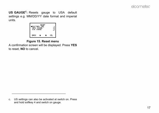
US GAUGEC: Resets gauge to USA defaultsettings e.g. MM/DD/YY date format and imperialunits.
Figure 15. Reset menuA confirmation screen will be displayed. Press YESto reset, NO to cancel.
c. US settings can also be activated at switch on. Pressand hold softkey 4 and switch on gauge.

SELECT STATSNO. OF READINGSMEANSTD DEVIATIONCOEF OF VARIAT’NHIGHEST READINGLOWEST READING
DELETED READINGTAGDELETE
SET CLOCK/DATETIME/DATEDISPLAY WHEN OFFDISPLAY WHEN ON
SET ALARMALARM ONSET TIME 00:00
DATE FORMATDD/MM/YYYYMM/DD/YYYY
BAUD RATE12002400480096001440019200
Op_456_3_English.book Page 18 Thursday, May 24, 2007 9:18 PM
R
18
4.4 MAIN MENU - EXTENDED MENU ONTo toggle EXTENDED MENU on/off select MENU/EXTENDED MENU/SEL
MENUBACKLIGHTCALIBRATION LOCKEDEXTENDED MENUPRINT/OUTPUTDELETECAL METHODSETUPABOUTRESET
STATSENLARGE STATSSTATS ON LCDDISPLAY F1CLEAR STATSSELECT STATS
DATAEXIT BATCHINGOPEN NEW BATCHOPEN EXISTING BATCHREVIEW BATCHESSET LIMITSFREE MEMORY
CALPROBE CALIBRATION
CAL METHODSMOOTH2 POINTROUGHSPECIAL SUBZERO OFFSETSET OFFSETISOSSPC 2004SWEDISHAUSTRALIAN
DELETELAST READINGSINGLE BATCHALL BATCHES
SETUPSTATISTICSDATAPROBEUNITSCLOCK/ALARMAUTO SWITCH OFF 1OUTPUTBEEP VOLUME 3LANGUAGESLARGE FONTSSOFTKEYS LOCKEDOPENING SCREEN
ABOUTGAUGE INFORMATIONPROBE INFORMATIONCONTACTHELP
RESETFACTORY CALINTL GAUGEUS GAUGE
PRINT/OUTPUTSINGLE BATCHALL BATCHESCURRENT STATISTICS
OUTPUTBLUETOOTH PC REPLYBAUD RATERS232 BIT IMAGERS232 PLAIN TEXT
CLOCK/ALARMSET CLOCK/DATESET ALARMSET DATE FORMAT
DATASOFTKEY ENABLEDSHOW DATE STAMPDELETED READING
STATISTICSSOFTKEY ENABLEDSELECT STATSDISPLAY F1

R
19
either in immediate mode or in
E YOU SURE? (Figure 17).
e last reading confirmation screen
to include reading in statisticalftkey to delete reading. to delete gauge displays LASTAILABLE (Figure 18).
e last reading not available screen
Op_456_3_English.book Page 19 Thursday, May 24, 2007 9:18 PM
The following features are added to the MENUwhen EXTENDED MENU is active:
PRINT/OUTPUTOutputs data to a printer or to a PC. A single batchof readings, all batches of readings, or the currentstatistical summary can be output via Bluetooth® orthe RS232 interface.To use this function, first setup using:MENU/SETUP/OUTPUT - see “OUTPUT:” onpage 22.If no printers have been setup, PRINT/OUTPUT willdisplay a NOT AVAILABLE message.
DELETEDeletes last reading only, a single batch of readingsor all batches of readings (Figure 16).
Figure 16. DELETE screen
LAST READINGDeletes last readingbatch mode.Gauge displays AR
Figure 17. Delet
Press NO softkey summary or YES soIf there is no readingREADING NOT AV
Figure 18. Delet
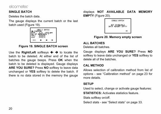
AILABLE DATA MEMORY.
Memory empty screen
.RE YOU SURE? Press NO
ta unchanged or YES softkey toches.
calibration method from list ofration method” on page 23 for
nge or activate gauge features:ates statistics feature..elect stats” on page 33.
Op_456_3_English.book Page 20 Thursday, May 24, 2007 9:18 PM
R
20
SINGLE BATCHDeletes the batch data.The gauge displays the current batch or the lastbatch used (Figure 19).
Figure 19. SINGLE BATCH screen
Use the Right/Left softkeys to locate thebatch to be deleted. At either end of the list ofbatches the gauge beeps. Press OK when thebatch to be deleted is displayed. Gauge displaysARE YOU SURE? Press NO softkey to leave dataunchanged or YES softkey to delete the batch. Ifthere is no data stored in the memory the gauge
displays NOT AVEMPTY (Figure 20)
Figure 20.
ALL BATCHESDeletes all batchesGauge displays Asoftkey to leave dadelete all of the bat
CAL METHODAllows selection ofoptions - see “Calibmore details.
SETUPUsed to select, chaSTATISTICS: ActivStats softkey on/offSelect stats - see “S

R
21
appear in the batch (with a tag-), but they are not included inns. are permanently deleted.ual function probes (FNF and F1mode.t from Automatic, F or N.t from F1 or F2.utomatically set by the probe
user can manually override theelect from µm, mm, mil, thou or
llows setting of time, date andd setting of the date format
DD/YY (Figure 23).
LOCK/ALARM screen
be set to be displayed on the topcreen when the gauge is on.
Op_456_3_English.book Page 21 Thursday, May 24, 2007 9:18 PM
Display - see “Display” on page 32.DATA: Activates DATA softkey, SHOW DATESTAMP option and selects the DELETEDREADING menu (Figure 21).
Figure 21. DATA menu screen
SOFTKEY ENABLED allows DATA softkey to beturned off when EXTENDED MENU is active.SHOW DATE STAMP - toggles date stamp on oroff in Review Batches - see “Review batches” onpage 38.DELETED READING screen (Figure 22) allowsreadings to be tagged or deleted.
Figure 22. DELETED READING screen
TAG - readings stilldeleted symbol statistical calculatioDELETE - readingsPROBE: Only for d2). Changes probe FNF probes - selecF1 2 probes - selecUNITS: Units are atype, however the automatic setting. Sinch.CLOCK/ALARM: Aalarm functions anDD/MM/YY or MM/
Figure 23. C
Time and date can line of the reading s

erring readings to a computer”er information.be set at values from 1200 tovalue is 9600 baud.GE Toggle tick box to
When activated, readings areinterface as they are taken. Allters are output as bit-maps. Thisthe Elcometer Miniprinter (seee 50).EXT Toggle tick box to
When activated, readings arenterface as they are taken. Theard ASCII characters from thesetd. This allows printing on
the Elcometer Miniprinter, e.g.r PC via Elcometer software
perTerminal.hanges volume.
in Text is selected the following lan-utput as English: Chinese, Greek,se, Korean, Russian, Lithuanian,
Op_456_3_English.book Page 22 Thursday, May 24, 2007 9:18 PM
R
22
Time and date can be set to be displayed in largedigits when the gauge is switched off.AUTO SWITCH OFF: Changes delay beforegauge switches off when displaying ReadingScreen.• Minimum = 1 minute• Maximum = 10 minutes• Default = 1 minuteAuto switch off may be disabled by selecting ‘off’ (Inthis case, switch off using On/Off key .)OUTPUT: Selects Bluetooth® PC Reply option,baud rate (Figure 24) and activates data output viathe interfaces - see “Interfaces” on page 12.
Figure 24. OUTPUT screen
BLUETOOTH PC REPLY When the box is ticked,and a Bluetooth® connection is establishedbetween your gauge and a PC, the gauge willexpect a reply from the PC after each reading is
taken. See “Transfon page 40 for furthBAUD RATE can 19200. The default RS232 BIT IMAactivate/deactivate.sent to the RS232 images and characallows printing on “Miniprinter” on pagRS232 PLAIN Tactivate/deactivate.sent to the RS232 igauge sends standCourier New font devices other thanRS 232 printers o(page 40) or via HyBEEP VOLUME: C
d. When RS232 Plaguages will be oHebrew, JapaneFarsi.

R
23
e softkey functions disappearreen 5 seconds after the readingdisplayed, or 5 seconds after To view the functions again,e four softkeys.re always visible in menus.
: Disables the openingso that the gauge switches on to screen.
ADJUSTMENT
ent is the process of setting thealues of thickness to ensurent substrate types, shapes and
an FNF probe it must bee ferrous mode and in the non-
sure accuracy of reading.
METHOD the gauge can be adjustedHOD) using several different
Op_456_3_English.book Page 23 Thursday, May 24, 2007 9:18 PM
• 0 = off• 5 = loudest• Default = 3LANGUAGES: Allows selection of language.If a personalised welcome screen has beendownloaded into the gauge (see page 45), OpeningScreen must be activated to display this screen.LARGE FONTS: When ticked, displays all menusand screens using double height, single width fonts(for improved legibility, if needed).
Figure 25. Large fonts enabled
SOFTKEYS LOCKED: When ticked, the softkeyfunctions will always be displayed.
Figure 26. Softkeys locked/unlocked
When un-ticked, thfrom the reading scscreen has been pressing any key.press any one of thSoftkey functions aOPENING SCREEN(welcome) screens display the reading
5 CALIBRATION
Calibration adjustmgauge to known vaccuracy on differesurface finishes.Note: When usingcalibrated in both thferrous mode to en
5.1 CALIBRATIONThe calibration of(MENU/CAL MET

is method uses the 2-Pointual substrate materials such astypes of stainless steel, highl aluminium alloys, etc.is is the method described inoatings on steel surfaces
t cleaning. The calibration usese technique, and a correction is applied to each reading toct of the roughened surface; thehe surface profile - see Table 1. screen sets and changes theurface roughness This value isero Offset calibration method.
on values as detailed in ISO 19840
ing Correction Value(µm) (Zero Offset)
102540
Op_456_3_English.book Page 24 Thursday, May 24, 2007 9:18 PM
R
24
methods described in National and InternationalStandards.The calibration adjustment method chosen isdependant on the condition of the substrate to bemeasured and is indicated on the screen by asymbol (Figure 27):
Figure 27. CAL METHOD screen
SMOOTH: Smooth surface calibration where thegauge is set to zero on the uncoated surface and aknown thickness above the expected thickness ofthe coating.2POINT: Calibration on a thin value and a thickvalue either side of the expected thickness. Thisenhances the accuracy of the gauge over thethickness range defined by the two values.ROUGH: A calibration method similar to 2-Point.This enhances the accuracy of the gauge over thethickness range defined by the two values.
SPECIAL SUB: Thcalibration for unuscast iron, certain carbon steel, speciaZERO OFFSET: ThISO 19840 for croughened by blasthe smooth surfacvalue (zero offset)account for the effevalue depends on tSET OFFSET: Thisoffset for different sused only with the Z
Table 1: Correcti
Profile accordto ISO 8503-1
FineMediumCoarse

R
25
ibration method is changed, e.g.ough, the gauge will display a).
alibration required screen
is pressed the CAL softkeydings Screen will flash to warnustment is still required. Whileymbol is flashing new batches
y is pressed the calibrationre is activated - see “Calibrationre” on page 27.
Op_456_3_English.book Page 25 Thursday, May 24, 2007 9:18 PM
5.2 PRESET CALIBRATION METHODSThe gauge also contains four preset calibrationmethods which follow relevant standards. Theseset the calibration method and the data collectionmethod (data collection method is only set when inbatching mode).ISO: (ISO 19840) This uses the Zero Offsetcalibration method with counted average datacollection set to 5 readings.SSPC: (SSPC-PA2 2004) This uses the 2-Pointcalibration method with counted average set to 3readings.SWEDISH: (SS 18 41 60) This uses the 2-Pointcalibration method with counted average set to 5readings.AUSTRALIAN: (AS 3894) This uses the ZeroOffset calibration method with a correction value of1/3 the surface profile peak-to-valley height and acounted average data collection set to 5 readings.
Note: When the calfrom Smooth to Rmessage (Figure 28
Figure 28. Rec
If the NO softkeysymbol on the Reathat calibration adjthe CAL softkey scannot be opened.If the YES softkeadjustment proceduadjustment procedu

5 mm (200 mils) and 13 mmauges it will be necessary tore 29). Care must be taken to
placing the foil labels between
g foils to increase thickness
: Thickness standards usingterials coated with hardwearingeasured using techniques
gauge.are most often used to confirmets its specifications if it is not (shims).
Serial no.Inspected bymicron mils/thou
502 19.75
TK1009
Seria
l no.
Insp
ecte
d by
micr
onm
ils/th
ou
176.
16.
93
TK10
10
Op_456_3_English.book Page 26 Thursday, May 24, 2007 9:18 PM
R
26
5.3 CALIBRATION FOILS AND STANDARDSCalibration adjustment should be carried out withthe appropriate probe on the same type of metal,the same curvature and similar finish to the item tobe measured. It is best to use an uncoated sampleof the items to be tested.Calibration can be carried out using measured foilsor coated standards.FOILS (SHIMS): These are coating thicknessstandards which have been measured usingtechniques independent of the gauge. They areideal for calibration because they provide a knownvalue of thickness on the actual substrate to bemeasured. Calibration certificates for foils areavailable upon request.When using foils care must be taken to keep thefoils clean and free from dust and to avoid damageby creasing particularly the thinner foils. Alwaysremove a foil from its storage wallet before use.When calibrating a High Temperature PINIP™Probe use the special thickness standards suppliedwith the probe - see “Calibrating High TemperaturePINIP™ Probes” on page 31.
Note: To calibrate(500 mils) range gstack the foils (Figuavoid errors due tothe foils.
Figure 29. Stackin
COATED STANDARDStypical substrate mamaterials and mindependent of the Coated standards that the gauge mepossible to use foils

R
27
air and press CAL softkey
1 - on thickness standard
turns the gauge to the Readinge Calibration Procedure withoutnges.llows the user to take readingsuracy of the current calibration.s do not affect statistical
nd are not added to batch
on calibration standard. Theay a reading. then replace on calibratione displays the average ( ) of
Op_456_3_English.book Page 27 Thursday, May 24, 2007 9:18 PM
5.4 CALIBRATION ADJUSTMENT PROCEDURECalibration adjustment can be carried out at anytime by pressing CAL softkey from the readingscreen. To prevent inadvertent calibrationadjustment the CAL softkey can be locked(MENU/CALIBRATION LOCKED).The user is guided through the operation of thechosen calibration procedure by means ofinstructions and illustrations on the graphicsscreen. Audible warnings are also provided whenaction is required, e.g. when the probe must beplaced down to get a reading.If the routine is interrupted in any way the previoussettings will be restored until after the full calibrationroutine has been completed or the reset has beencompleted.The screen detail depends on the calibrationmethod chosen, but the calibration is in two steps.The following example is for a Smooth Calibrationadjustment.
Step 11. Hold probe in
(Figure 30).
Figure 30. Step
ESC softkey reScreen from thmaking any chaTEST softkey ato verify the accThese readingcalculations amemory.
2. Place probe gauge will displ
3. Lift probe andstandard. Gaug

icates over-range (Figure 32).ing within range clears this
. Over-range reading
n uncoated standard or zerouge will take and display a
then replace on uncoatedro plate. Gauge displays the
f these readings and the last
Op_456_3_English.book Page 28 Thursday, May 24, 2007 9:18 PM
R
28
these readings and the last reading. Repeatthis action until a stable reading is obtained.
Figure 31. Step 1 - Calibration adjustment on thickness standard
To reject the displayed reading and start thecalibration procedure again, press both the Upand Down softkeys at the same time.To adjust the displayed reading until it iscorrect relative to the thickness standard usethe Up/Down softkeys.
4. Press SET softkey to accept the value.
Note: - - - indTaking a readscreen.
Figure 32
Step 21. Place probe o
plate. The gareading.
2. Lift probe andstandard or zeaverage ( ) o
First reading Second reading
Average
Last

R
29
l display the option to test thee gauge.
EST READINGS screen
NO softkey to complete thestment procedure and return
e reading screen, or proceed tongs - see Taking test readings
Op_456_3_English.book Page 29 Thursday, May 24, 2007 9:18 PM
reading. Repeat this action until a stablereading is obtained.
Figure 33. Step 2 - Calibration adjustment on uncoated sample
To reject the displayed reading and start Step2 of the calibration procedure again, press theReset softkey .
3. Press ZERO softkey to zero the display (Figure34).
Figure 34. Zero the display
4. Press SET softkey to accept this value.
The gauge wilcalibration of th
Figure 35. T
5. Either press calibration adjuthe gauge to thtake test readibelow.
First reading Second reading

ken on a thin standard valuecoated base.
tep 2 - On thin standard
ing will display the average. Thisl for rough surfaces as it allowsrface to be accounted for in theent, therefore improving thege.
- Calibration adjustment on hin standard
g Second reading
Op_456_3_English.book Page 30 Thursday, May 24, 2007 9:18 PM
R
30
Taking test readingsPress YES softkey (see previous section) to taketest readings. This allows the calibration of thegauge to be tested without adding readings to datamemory or contributing to the statisticalcalculations.
Figure 36. TEST READINGS screen
NEXT softkey returns the gauge to Step 1 of thecalibration adjustment procedure.ESC softkey exits the calibration adjustmentprocedure and returns the gauge to the readingscreen.
Other calibration methodsFor the 2-POINT, ROUGH and SPECIALSUBSTRATE calibration methods Step 2 requires
readings to be tainstead of on an un
Figure 37. S
Repeating the readis particularly usefuvariations in the sucalibration adjustmaccuracy of the gau
Figure 38. Step 2t
First readin

R
31
3 Top has a Statistics featureulates and displays a statisticalgs as they are taken. The
ons are also applied to thehin a single batch in memory.ED MENU is active MENU/SEL), press STATS
TATS MENU (Figure 39).
e 39. Stats menu
s available are:dings
tion ariation g g
Op_456_3_English.book Page 31 Thursday, May 24, 2007 9:18 PM
Calibrating High Temperature PINIP™ ProbesSpecial thickness standards are supplied withF1 2 High Temperature PINIP™ Probes - seepage 44. These thickness standards should beused in place of the calibration standard in Step 1of “Calibration adjustment procedure” on page 27.1. Place appropriate thickness standard over end
of PINIP™ probe.2. Press CAL softkey.
3. Place probe on hote surface and take areading.
4. Lift probe and then replace on hot surface totake second reading.
5. Repeat as necessary until reading is stable.6. Press SET to accept value.7. Remove thickness standard from end of
PINIP™ probe.8. Proceed with Step 2 - see page 28.
6 STATISTICS
The Elcometer 456(STATS) which calcanalysis of readinstatistical calculatireadings stored witWhen EXTEND(MENU/EXTENDEDsoftkey to access S
Figur
The statistical value• Number of Rea• Mean • Standard Devia• Coefficient of V• Highest Readin• Lowest Readin
e. The temperature of the surface used for calibrationshould be equal to the temperature of the substratebeing measured.

yed and the CLOCK is not
ng screen with all statistics
using dual function probes.he types of readings used in then when a dual function probe is
nd N combinedf
1 and F2 combinedf
re combined a symbol will beReading Screen (Figure 41).
Combined statistics symbol
Op_456_3_English.book Page 32 Thursday, May 24, 2007 9:18 PM
R
32
See “Select stats” on page 33 and “Statisticsterminology” on page 46.
6.1 ENLARGE STATSDisplays the chosen statistical values as double-height characters. The example screens (Figure40) appear when all the statistical values areselected. The Up/Down softkeys can be used tomove through the list. OK softkey returns to theReading Screen.
Figure 40. Enlarged statistics
6.2 STATS ON LCDActivates the presentation of the chosen statisticalvalues on the reading screen. If STATS ON LCD isactivated while CLOCK ON LCD is active, the
STATS are displadisplayed.
Figure 41. Readi
6.3 DISPLAYOnly applies whenAllows selection of tstatistical calculatioconnected.Probe OptionsFNF F, N or F aF1 2 F1, F2 or F
f. When readings adisplayed on the

R
33
he gauge takes readings and but does not store any readings43).
g screen - Immediate mode
gauge takes readings and and stores readings in memoryuge stores readings in one of upches.ing) allows reading data to beto allow easier analysis of largeex assemblies.
ding screen - Batch mode3 Top has memory capacity forgs in up to 999 batches.
Op_456_3_English.book Page 33 Thursday, May 24, 2007 9:18 PM
6.4 CLEAR STATSResets to zero all statistical values selected inSTATS MENU/DISPLAY.
6.5 SELECT STATSAllows the user to chose which statistical values aredisplayed. The default condition is all values (Figure42).
Figure 42. Select stats menu
Use Up/Down softkeys to move cursor and SELsoftkey to select or deselect the statistical values.
7 BATCHING
The Elcometer 4563 operates in one of two modes;immediate or batch.
IMMEDIATE MODE: Tcalculates statisticsin memory (Figure
Figure 43. Readin
BATCH MODE: The calculates statistics(Figure 44). The gato 999 separate batBatch mode (batchcollected in groups structures or compl
Figure 44. Rea
The Elcometer 456up to 50 000 readin

h mode - see page 37. This ising’ a batch.pically used when several
eing tested, each with differentnd calibration settings. Cloningngs for a product to be quicklylicated. To clone a batch, first to be cloned (see section 7.3d then OPEN NEW BATCH.AL softkey symbol is flashing,ot be opened. Calibrate theing a new batch. FNF probes
d in F mode and in N mode.
h in immediate modeis opened the following settingsbatch from immediate mode:hodd)stmentethod and offset must be set
the new batch. Calibration changed after the batch has
Op_456_3_English.book Page 34 Thursday, May 24, 2007 9:18 PM
R
34
Batching is configured using the DATA MENU.To access the DATA MENU (Figure 45) press theDATA softkey (this softkey is only displayed withEXTENDED MENU on).
Figure 45. DATA MENU screen
7.1 EXIT BATCHINGThis option returns the gauge to immediate modeand no further readings are stored in memory. Thegauge returns to the Reading Screen.
7.2 OPEN NEW BATCHThis option opens (creates) a new batch using thenext available batch number.• To create a batch with new calibration settings
use OPEN NEW BATCH in immediate mode -see page 34.
• To create a batch with a copy of the calibrationsettings from another batch use OPEN NEW
BATCH in batcknown as ‘clonCloning is typroducts are bmeasurement aallows the settiand easily dupopen the batchon page 38) an
Note: While the Cnew batches canngauge before openshould be calibrate
Opening new batcWhen a new batch are copied into the • Calibration met• Offset (if applie• Calibration adjuNote: Calibration mbefore opening adjustment can be
R
35
NEW BATCH screen (Figurent batch settings.
OPEN NEW BATCH screen - mediate mode
Limits for the batch can beme once the batch has beenimits” on page 39.ethod must be set before OK
dn Method can be changed byollection Method softkey or
Lower and upper limits
Number of readings in batch (0)
Calibration method
Offset
Calibration type
Op_456_3_English.book Page 35 Thursday, May 24, 2007 9:18 PM
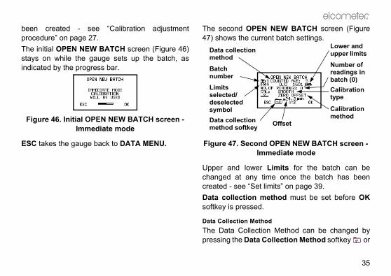
been created - see “Calibration adjustmentprocedure” on page 27.The initial OPEN NEW BATCH screen (Figure 46)stays on while the gauge sets up the batch, asindicated by the progress bar.
Figure 46. Initial OPEN NEW BATCH screen - Immediate mode
ESC takes the gauge back to DATA MENU.
The second OPEN47) shows the curre
Figure 47. SecondIm
Upper and lower changed at any ticreated - see “Set lData collection msoftkey is pressed.
Data Collection MethoThe Data Collectiopressing the Data C
Batch number
Data collection method
Data collection method softkey
Limits selected/deselected symbol

can be changedh by pressing.
ng data collection methodted average n = 5
tion method (see “Preset calibratione 25) is selected, the value for ‘n’d. shown on the softkey can be any2 and 255.
Op_456_3_English.book Page 36 Thursday, May 24, 2007 9:18 PM
R
36
. The display toggles between two options,normal and counted average:• NORMAL - Each reading is added to the
number of readings and contributes to thestatistical calculation.
• COUNTED AVE: n - Readings are taken inpreset groupsg, the default being 5 readings,n=5 (Figure 48). At the end of each group thegauge beeps and calculates the average forthe group and stores this average value, whichis used for the statistical calculation. Theindividual readings in the group are not stored.
The value for nthe n=5i softkey
Figure 48. SettiCoun
g. When using an FNF probe in AUTO mode the firstreading in each group will ‘lock’ the probe to that sub-strate for the whole of the group.
h. If a preset calibramethods” on pagcannot be adjuste
i. The value for ‘n’number between

R
37
NEW BATCH screen displays’.
OPEN NEW BATCH screen -Batch mode
NEW BATCH screen (Figurebatch settings.
OPEN NEW BATCH screen -Batch mode
batch.
tically allocates the next batchw batch is created. Up to 999ve at any time. Deleted batches
Cloned batch symbol
Op_456_3_English.book Page 37 Thursday, May 24, 2007 9:18 PM
Opening new batch in batch modeOpening a new batch in batch mode duplicates(clones) an existing batch.Cloning copies the following settings to the newbatch:• Limits• Calibration method• Data collection method• Offset (if applied)• Calibration adjustmentNote: Calibration method, data collection methodand offset cannot be changed once the clonedbatch has been created. Calibration adjustment andlimits can be changed after the batch has beencreated - see “Calibration adjustment procedure” onpage 27 and “Set limits” on page 39.
The initial OPEN ‘CURRENT BATCH
Figure 49. Initial
The second OPEN50) shows the new
Figure 50. Second
Press OK to create
Batch numberingThe gauge automanumber when a nebatches can be acti

the batch calibration details areer can locate and fit the original
HEStent of any batch to be displayed
VIEW BATCHES screen
keys move the cursor through
oftkey toggles the status area
hes screen can contain then:cluding symbols indicatingare above or below limits ifctivated).
Op_456_3_English.book Page 38 Thursday, May 24, 2007 9:18 PM
R
38
are removed from the list so that batch numbersabove 999 are valid. A deleted batch numbercannot be reused until all the batches are deleted,when the batch number count starts again at 1.
7.3 OPEN EXISTING BATCHThis allows any batch to be opened to add readings.If the gauge is switched off with the batch open, thecurrent batch will re-open when the gauge isswitched back on.Note: If the probe is changed to another probe ofthe same type the gauge will display a warning(Figure 51).
Figure 51. Changed probe warning screen
If NO is selected, the serial number and calibrationdata of the new probe are saved into the currentbatch as a data entry.
If YES is selected, retained and the usprobe, if they wish.
7.4 REVIEW BATCThis allows the con(Figure 52).
Figure 52. RE
The Up/Down softthe list of readings.The Status son/off.The Review Batcfollowing informatio• Readings (in
whether they LIMITS ON is a
Status area

R
39
and LOWER limit values moveit required and press SEL.lay the current settings (Figureare for illustration only.
ing upper and lower limits
with Up/Down softkeys. When displayed, press OK to enter.tivated the out-of-limits reading a triple beep and a red light onreading within limits is indicatednd a green light. Out-of-limits
ill be stored in the batch and canatch is reviewed.
Op_456_3_English.book Page 39 Thursday, May 24, 2007 9:18 PM
• Date stamp (entered whenever the batch isopened).
• Probe change (includes date stamp and probeserial number).
• Recalibration (includes date stamp,recalibration stamp and, for dual functionprobes, the probe mode).
The status area in the bottom half of the screendisplays the batch number and the type and serialnumber of the probe used when the batch wascreated.
7.5 SET LIMITSUpper and lower values can be set by the user tomonitor specification values.To activate limits tick the LIMITS ON box (Figure53).
Figure 53. SET LIMITS screen
To set the UPPER the cursor to the limThe gauge will disp54). Values shown
Figure 54. Sett
Adjust the values the correct value isWith LIMITS ON acwill be indicated bythe keypad LED. A by a single beep asymbols and wbe seen when the b

oftware for Measurementware allows the user to transferemory of the gauge to a PC forsis and reporting. Data can beg the PC connection cable or
a can also be transferred as the are taken. ElcoMaster includesat you may need together with
er to let you design your reportssh to see them. ElcoMaster can create personalised welcome
load them to your gauge.ta Conversion Software. Thisrts existing measurement dataformat. The following types of
data can be converted;S Win, EDCS Plus and EDCS.n also be downloaded from thewww.elcometer.com/downloads
G USING A CABLEgauge to your PC using the
Op_456_3_English.book Page 40 Thursday, May 24, 2007 9:18 PM
R
40
7.6 FREE MEMORYThis option displays the amount of free memoryavailable for storage of readings (Figure 55).
Figure 55. FREE MEMORY screen
8 TRANSFERRING READINGS TO A COMPUTER
Your gauge comes complete with software whichallows data to be transferred to a PC usingBluetooth® or the optional PC connection cable.The CD supplied with your gauge includes thefollowing software:
• Elcometer Data Transfer Software (EDTS+
Excel Link). This software allows the user totransfer data from the memory of the gaugeinto Microsoft Excel using the PC connectioncable. The data can then be processed insoftware such as Word or Excel.
• ElcoMaster SData. This softdata from the marchiving, analytransferred usinBluetooth®. Datmeasurementsall the charts tha report designthe way you wialso be used toscreens and up
• ElcoMaster Dasoftware conveto ElcoMaster measurement Elcometer EDC
All this software caElcometer website
8.1 TRANSFERRIN1. Connect your
optional cable.

R
41
ow the Bluetooth® PIN (in theigure 56, ‘19400’):
re 56. PIN code
ifferent PIN - use the PIN shownrmation screen.
EASUREMENTS AS THEY
can be transferred from youra Bluetooth® connection as the
s a feature which checks that ay the gauge has arrivedr PC. If the reading does not
n error message is displayed onrther readings cannot be taken
Op_456_3_English.book Page 41 Thursday, May 24, 2007 9:18 PM
2. Switch on your gauge and ensure the ReadingScreen is displayed.
3. Start the software and follow the instructionsincluded with the software.
8.2 TRANSFERRING USING A BLUETOOTH® CONNECTIONFull instructions on how to interface your gauge withElcoMaster and download data are included withthe ElcoMaster help file supplied with the software.
VERIFYING A BLUETOOTH® CONNECTIONWhen a Bluetooth® connection is establishedbetween your gauge and a PC, the gauge producestwo high pitch beeps and shows a flashingBluetooth® icon in the top right corner of thedisplay. When the connection is closed or lost, thegauge produces two lower pitch beeps and the iconis removed.
BLUETOOTH® PINIf at any time ElcoMaster requests a PIN number foryour gauge, switch on your Elcometer 4563 andselect MENU>ABOUT>GAUGE INFORMATION.
The display will shexample shown in F
Figu
Each gauge has a don your Gauge Info
TRANSFERRING MARE TAKENMeasurement datagauge to a PC via readings are taken.Your gauge includereading taken bsuccessfully at youarrive at your PC, ayour gauge and fuuntil it is cleared.

of probes is available for theating Thickness Gauge. Probes
non-ferrous (N) and dual (FNF) operation are availableuilt-in) or separate options.e fully interchangeable and areard, PINIP™ and miniature
lug-In Integral Probe) is an which plugs in to a separates all the benefits of an integral
ibility of a separate gauge in a
probes permit measurementsricted.
PROBES the thickness of non-magneticic substrates. They can be usedlvanising, enamel, powder paint,ther coatings such as electro-
to steel or iron.
Op_456_3_English.book Page 42 Thursday, May 24, 2007 9:18 PM
R
42
To use this feature, tick the Bluetooth® PC Replybox under MENU>SETUP>OUTPUT - see“OUTPUT:” on page 22.When the box is ticked, and a Bluetooth®
connection is established between your gauge anda PC, the gauge will expect a reply from the PCafter each reading is taken.If this reply is not received within half a second ofsending the reading, an error message will bedisplayed (Figure 57).
Figure 57. Bluetooth PC Reply error message
If the Bluetooth® connection is still established andthe reply is received after half a second then themessage will clear automatically, (this indicates thatthe Bluetooth® connection is operating at the limit ofits range). If the Bluetooth® connection has beenlost, then the error message will remain on thescreen until a key is pressed.
9 PROBES
An extensive rangeElcometer 4563 Cofor ferrous (F), ferrous/non-ferrousas either integral (bSeparate probes aravailable in standformats.PINIP™ format (Pintegral style probegauge. This providegauge and the flexsingle unit.Miniature separatewhere space is rest
9.1 FERROUS (F) F probes measurecoatings on magneton paint, plastic, gahard chrome and oless nickel applied

R
43
CHANGEABILITY shows which probes can be
pes of Elcometer 4563 Gauge.
Gauge TypeF N FNF
****
e
igh
straight 45° 90°
Op_456_3_English.book Page 43 Thursday, May 24, 2007 9:18 PM
9.2 NON-FERROUS (N) PROBESJ
N probes measure the thickness of non-metalliccoatings on non-magnetic metals. They can beused on anodising, paint, plastic coatings, powderpaint, etc. applied to aluminium, brass, non-magnetic stainless steel, etc.
9.3 DUAL FERROUS/NON-FERROUS (FNF) PROBESFNF probes are dual function, F and N in one probe.FNF gauges will automatically detect the type ofsubstrate and set the mode accordingly.Alternatively the mode can be set manually - see“PROBE:” on page 21 and “Coatings on galvanisedor metallised steel” on page 44.
9.4 PROBE INTERThe following tableused in the three ty
j. Using an N probe (or an FNF probe manually set toN1) on a ferrous substrate will give a reading, but thereading will be incorrect.
Probe type
FER
RO
US
F1F2F1 2F3F1 right angleF2 right angleF1 2 right anglF1 telescopicF2 telescopicF1 PINIP™F2 PINIP™F1 2 PINIP™ HTempF3 PINIP™FM3 miniatureFM3 miniatureFM3 miniature

PERATURE PINIP™
robes are capable of measuringces up to 250°C (480°F). Wearate protective clothing and takevoid bodily contact with the hotsurement.maximum measurement speedrobes - see page 47.cial calibration procedure - seemperature PINIP™ Probes” on
GALVANISED OR EL fixed N1 mode may be used totings on galvanised, aluminiumayed steel substrates.uge to the N1 mode/PROBE).rate the gauge on a sample ofl - see “Calibration adjustment”
Op_456_3_English.book Page 44 Thursday, May 24, 2007 9:18 PM
R
44
* indicates probes available for integral typegauges.
9.5 F1 2 PROBESThe F1 2 scale combines the F1 scale with the F2scale in a single probe. The user selects theappropriate range for the work in hand. Theresolution of the gauge is dependent on the scaleselected on the gauge.
9.6 F1 2 HIGH TEMPROBES
These pon surfaappropricare to a
surface during meaDo not exceed the when using these pNote: Refer to spe“Calibrating High Tepage 31.
9.7 COATINGS ONMETALLISED STEThe FNF probe in measure paint coa(Al) or zinc (Zn) spr1. Set the ga
(MENU/SETUP2. Zero and calib
the coated steeon page 23.
NO
N-F
ERR
OU
S
N1 *N2N1 right angleN1A anodiser’sN1 PINIP™NM3 miniature straightNM3 miniature 45°NM3 miniature 90°
DU
AL FNF1 *
FNF1 right angleFNF PINIP™
Probe type Gauge TypeF N FNF

R
45
D TRANSIT
ge incorporates a Liquid Crystal(LCD). If the display is heated°C (120°F) it may be damaged. happen if the gauge is left in a sunlight.uge in its carrying pouch when ies from the gauge and storee gauge is to remain unused fore. This will prevent damage to
event of malfunction of the
E
the finest hand-held coating the world. If looked after, it will
ot contain any user-serviceable unlikely event of a fault, theturned to your local Elcometer
Op_456_3_English.book Page 45 Thursday, May 24, 2007 9:18 PM
Care must be taken to ensure that thecalibration conditions are not affected bychanges in the zinc or aluminium coatingthickness. This can be determined by checkingthe zero over an area of the galvanised ormetal-coated steel. Metal coatings on steelabove 50 µm (2 mil/thou) should be consistentenough to obtain a stable zero on the layer ofmetal.
3. Take readings.
10 PERSONALISED WELCOME SCREEN
A personalised welcome screen can be created anddownloaded into the gauge.Screen dimensions are 128 pixels x 64 pixels. Thewelcome screen is typically used to personalise thegauge with a logo, serial number, user name, etc.This is the first screen displayed when the gauge isswitched on.Use your Bluetooth® interface or PC connectioncable with ElcoMaster software to create andupload the screen - see the instructions includedwith ElcoMaster.
11 STORAGE AN
This gauDisplay above 50This can
car parked in strongAlways store the gait is not being used.Remove the batterthem separately if tha long period of timthe gauge in thebatteries.
12 MAINTENANC
You own one of thickness gauges inlast a lifetime.The gauge does ncomponents. In thegauge should be re

TERMINOLOGY
Meaning
Coefficient of Variation. The standard deviation divided by the mean for a group of readings, expressed as a percentage.
The value of the maximum thickness in a group of readings.
The value of the minimum thickness in a group of readings.
The average of a group of readings; the sum of the individual readings divided by the number of readings.
Op_456_3_English.book Page 46 Thursday, May 24, 2007 9:18 PM
R
46
supplier or directly to Elcometer. Contact details arestored in the gauge - MENU/ABOUT/CONTACT.Worldwide: [email protected] USA/Canada: [email protected]: Probes will eventually wear. Probe life willdepend on the number of measurements takenand how abrasive the coating is. Probe life canbe prolonged by careful positioning of theprobe on the surface.Replacement separate and PINIP™ probes canbe fitted by the user without the need to returnthe gauge for service.Gauges with an integral probe have to bereturned for re-programming or replacement ifthe probe becomes worn or damaged.
13 STATISTICS
Term
COEF OF VARIAT’N
HIGHEST READING
LOWEST READING
MEAN

R
47
ATA
NT SPEEDinute.
high temperature materialsd must be reduced to preventthe probe. The maximumed of the High Temperature50°C (480°F) is 4 readings per
BSTRATE THICKNESS2 mils)
(4 mils) be taken on thinner substrates is carried out either side of thethickness, however gauges willnge when adjusted for thin
ATING TEMPERATUREobes: 150°C (300°F)INIP™ probes: 250°C (480°F)
Op_456_3_English.book Page 47 Thursday, May 24, 2007 9:18 PM
14 TECHNICAL D
14.1 MEASUREME>60 readings per mWhen measuring measurement speeoverheating of measurement spePINIP™ probe at 2minute.
14.2 MINIMUM SUFerrous: 300 µm (1Non-ferrous: 100 µmMeasurements canif 2-point calibrationrequired substrate have reduced rasubstrates.
14.3 PROBE OPERSeparate ferrous prHigh temperature P
NO. OF READINGS
Number of Readings. The running value for the number of readings taken in a group. In the case of the mode, the Number of Readings is the number of values recorded, not the total number of readings taken.
STD DEVIATION Standard Deviation. A statistical measure of the spread of values in a group of readings.
Term Meaning

ngs per minute.) Battery life isd when using the backlight.
ked in cardboard and plastic ensure that this packaging isan environmentally sensitive
your Local Environmental guidance.
S3 is complete with all the itemsted and take measurements.
must be disposed of carefully tontal contamination. Please consultmental authority for information on
egion.f any batteries in fire.tteries can be used if they are
he gauge.uced to approximately 25% of dry
using rechargeable batteries. Followrovided by the battery manufacturerand disposing of rechargeable
Op_456_3_English.book Page 48 Thursday, May 24, 2007 9:18 PM
R
48
Miniature probes without outer sleeve: 150°C (300°F)All other probes: 80°C (176°F)
14.4 PHYSICAL
14.5 POWER SUPPLYInternal batteries, 2 x LR03 (AAA), alkalinek drybatteries or rechargeablel equivalents.
Battery life30m hours to 40 hours continuous use with alkalinedry batteries. (15 000 to 20 000 readings at an
average of 8 readireduced by one thir
14.6 PACKAGINGThe gauge is pacpackaging. Pleasedisposed of in manner. Consult Authority for further
15 ACCESSORIE
The Elcometer 456required to get star
Weight (including batteries):
Separate Probe (FNF1), 190g (6.7oz)Separate Probe (PINIP™), 155g (5.5oz)Integral Probe, 130g (4.6oz)
Dimensions: 130 mm x 70 mm x 35 mm(5.12" x 2.76" x 1.38")
Gauge operating temperature:
0°C to 50°C (32°F to 120°F)Operation outside these limits depends upon climatic conditions.
Case: High impact ABS k. Alkaline batteriesavoid environmeyour local environdisposal in your rDo not dispose o
l. Rechargeable bacharged outside t
m. Battery life is redbattery life when the instructions pwhen charging batteries.

R
49
available. Consult your local
N CERTIFICATES FOR FOILSble to National Standards NIST are available on request.
ICATESults of a standard test on known full range of the probe. Order
mber TEST-456.
KNESS STANDARDS IFICATE
EMENT JIGioning on small components aig is available and an adapter
4 Values): T995111261ard (4 Values): T9951112712 Values): T995166001ard (2 Values): T995166011
Op_456_3_English.book Page 49 Thursday, May 24, 2007 9:18 PM
Many of the following accessories are optional.However, some are consumable items that mayneed to be replaced over the lifetime of the gauge.All these accessories are available from Elcometer,or your local Elcometer supplier. At time of orderingplease quote the sales part number which followsthe description of each accessory.
15.1 PROBESFull details of the extensive range of 456 probescan be obtained from Elcometer, your localElcometer supplier or the Elcometer website,www.elcometer.com.
15.2 FOIL SETS
Individual foils in the range 12.5 µm to 20 mm (0.5mil to 790 mils) and customised sets chosen from
this range are alsoElcometer supplier.
15.3 CALIBRATIOCertificates traceaincluding UKAS and
15.4 TEST CERTIFA certificate with resfoil values over theusing sales part nu
15.5 COATED THICINCLUDING CERT
15.6 PROBE PLACTo aid probe positprobe placement j
2.2 mm (85 mils) 8 pieces: T9904199F1.3 mm (51 mils) 3 pieces: T9904199G5.5 mm (220 mils) 4 pieces: T9904199J15 mm (595 mils) 4 pieces: T9904199K
Ferrous Standard (Non-Ferrous StandFerrous Standard (Non-Ferrous Stand

DS
TION CABLE
pin adapter may be required fororts.
® MODULE
ection cable T45616267
(Pack of 5): T9769992-f 20): T9999993-
ion: T45616161robe Version: T45616162
tion Cable (9- T99916217
odule: T99920130
Op_456_3_English.book Page 50 Thursday, May 24, 2007 9:18 PM
R
50
suitable for use with the full range of miniatureprobes is also available as an accessory.
15.7 PROBE ADAPTERS
15.8 Miniprinter42 column, rechargeable battery poweredMiniprinter complete with charger. Three chargeroptions:
Miniprinter spares
15.9 BENCH STAN
15.10 PC CONNEC
Note: A 9-pin to 25-certain PC RS232 p
15.11 BLUETOOTH
Probe placement jig: T95012880
Jumbo Hand Grip (F and N probes):
T9997766-
Jumbo Hand Grip (FNF probes): T99913225V Adapter for pipes (F & N probes):
T9997381-
V Adapter for pipes (FNF probes): T99913133
230V (UK Plug): X4569964B230V (European Plug): X4569964C110V (US Plug): X4569964D
456 to printer conn(25-pin):Ribbon Cassettes Paper Rolls (Box o
Integral Probe VersIntegral/Separate P
456 to PC Connecpin):
USB Bluetooth® M

R
51
WRIST HARNESS
Op_456_3_English.book Page 51 Thursday, May 24, 2007 9:18 PM
16 RELATED EQUIPMENT
Elcometer produces a wide range of coatingthickness gauges and associated paint inspectionequipment. Users of the Elcometer 4563 may alsobenefit from the following Elcometer products:• Uncured powder thickness gauges• Coatings analyser• Inspection management software• Mechanical coatings thickness gauges• Appearance testers• Adhesion testersFor further information contact Elcometer, yourlocal Elcometer supplier or visitwww.elcometer.com
17 FITTING THE
1. Pass harnessround pin
2. Pass harnessthrough loop
3. Pull tight

easured.
ion in range0 µm to 99.9 µm100 µm to 1500 µm0 mil to 4.99 mils5 mils to 60 mils0 mm to 0.99 mm1.0 mm to 5.0 mm0 mil to 49.9 mils50 mils to 200 mils0 mm to 1.99 mm2 mm to 13 mm0 mil to 99.9 mils100 mils to 500 mils0 µm to 99.9 µm100 µm to 500 µm0 mil to 3.99 mils4 mils to 10 mils0 mm to 1.99 mm2 mm to 25 mm0 mil to 99.9 mils100 mils to 980 mils0 mm to 1.99 mm2 mm to 30 mm0 mil to 99.9 mils100 mils to 1200 mils
Op_456_3_English.book Page 52 Thursday, May 24, 2007 9:18 PM
R
52
18 PROBE MEASUREMENT PERFORMANCE
Scale Total range Accuracya
a. Whichever is the greater. Lower value achieved when calibrated close to the thickness to be m
ResolutF1F1 2 (F1 mode)FNF1N1, N1A
0 µm to 1500 µm ±1% to ±3% or ±2.5 µm 0.1 µm1.0 µm
0 mil to 60 mils ±1% to ±3% or ±0.1 mil 0.01 mil0.1 mil
F1 2 (F2 mode)N2
0 mm to 5.0 mm ±1% to ±3% or ±0.02 mm 1.0 µm10 µm
0 mil to 200 mils ±1% to ±3% or ±1 mil 0.1 mil1 mil
F3 0 mm to 13 mm ±1% to ±3% or ±0.05 mm 1.0 µm10 µm
0 mil to 500 mils ±1% to ±3% or ±2.0 mils 0.1 mil1 mil
FM3NM3
0 µm to 500 µm ±1% to ±3% or ±2.5 µm 0.1 µm1.0 µm
0 mil to 10 mils ±1% to ±3% or ±1.0 mil 0.01 mil0.1 mil
F6 0 mm to 25 mm ±1% to ±3% or ±0.1 mm 10 µm100 µm
0 mil to 980 mils ±1% to ±3% or ±2.0 mils 1 mil10 mil
N6 0 mm to 30 mm ±1% to ±3% or ±0.05 mm 10 µm100 µm
0 mil to 1200 mils ±1% to ±3% or ±2.0 mils 1 mil10 mil

R
53
inimum mple ameter
Cal foil valuea
specified accuracy under these
mm (0.16”) 250 µm (10 mil)
mm (0.32”) 1 mm (40 mil)
mm (0.55”) 2.5 mm (100mil)
mm (0.24”) 250 µm (10 mil)
mm (0.32”) 250 µm (10 mil)
mm (0.16”) 250 µm (10 mil)
Op_456_3_English.book Page 53 Thursday, May 24, 2007 9:18 PM
19 PROBE CAPABILITIES
19.1 INTEGRAL PROBES
Probe typeMinimum convex surface diameter
Minimum concave surface radius
HeadroomMsadi
a. This is the recommended maximum calibration foil value to achieve themeasurements conditions
F1 (or F1 2 set for F1 operation)
4 mm (0.16”) 25 mm (0.98”) 130 mm (5.1”) 4
F1 2 (set for F2 operation)
4 mm (0.16”) 25 mm (0.98”) 135 mm (5.3”) 8
F3 15 mm (0.59”) 40 mm (1.57”) 150 mm (5.9”) 14
N1 (N) 35 mm (1.38”) 25 mm (0.98”) 130 mm (5.1”) 6
FNF1 (N) 38 mm (1.50”) 25 mm (0.98”) 135 mm (5.3”) 8
FNF1 (F) 4 mm (0.16”) 25 mm (0.98”) 135 mm (5.3”) 4

nimum mple ameter
Cal foil valuea
specified accuracy under these
m (0.16”) 250 µm (10 mil)
m (0.32”) 1 mm (40 mil)
m (0.16”) 250 µm (10 mil)
m (0.32”) 1 mm (40 mil)
m (0.16”) 250 µm (10 mil)
m (0.32”) 1 mm (40 mil)
mm (0.55”) 2.5 mm (100 mil)
x 51 mm" x 2")
5 mm (200 mil)
Op_456_3_English.book Page 54 Thursday, May 24, 2007 9:18 PM
R
54
19.2 SEPARATE FERROUS PROBES
Probe typeMinimum convex surface diameter
Minimum concave surface radius
HeadroomMisadi
a. This is the recommended maximum calibration foil value to achieve themeasurements conditions
F1 (or F1 2 set to F1) 4 mm (0.16”) 25 mm (0.98”) 85 mm (3.35”) 4 m
F1 2 (set to F2) 4 mm (0.16”) 25 mm (0.98”) 89 mm (3.50”) 8 m
F1 Right Angle(or F1 2 set to F1)
4 mm (0.16”) 25 mm (0.98”) 28 mm (1.10”) 4 m
F1 2 Right Angle(set to F2)
4 mm (0.16”) 25 mm (0.98”) 32 mm (1.26”) 8 m
F1 Telescopic 4 mm (0.16”) 25 mm (0.98”) 32 mm (1.26”) 4 m
F1 2 Telescopic 4 mm (0.16”) 25 mm (0.98”) 36 mm (1.42”) 8 m
F3 15 mm (0.59”) 40 mm (1.57”) 102 mm (4.02”) 14
F6 35 mm 170 mm 150 mm 51(2

R
55
nimum mple meter
Cal foil valuea
specified accuracy under these
m (0.24”) 250 µm (10 mil)
m (0.24”) 250 µm (10 mil)
m (0.24”) 250 µm (10 mil)
mm (0.55”) 1 mm (40 mil)
mm Any
Op_456_3_English.book Page 55 Thursday, May 24, 2007 9:18 PM
19.3 SEPARATE NON-FERROUS PROBES
Probe typeMinimum convex surface diameter
Minimum concave surface radius
HeadroomMisadia
a. This is the recommended maximum calibration foil value to achieve themeasurements conditions
N1 35 mm (1.38”) 25 mm (0.98”) 85 mm (3.35”) 6 m
N1 Right Angle 35 mm (1.38”) 25 mm (0.98”) 28 mm (1.10”) 6 m
N1A Anodiser’s Probe
35 mm (1.38”) 25 mm (0.98”) 85 mm (3.35”) 6 m
N2 100 mm (3.97”) 150 mm (5.90”) 85 mm (3.35”) 14
N6 Flat surface 400 mm 160 mm 58

nimum mple ameter
Cal foil valuea
specified accuracy under these
m (0.32”) 250 µm (10 mil)
m (0.16”) 250 µm (10 mil)
m (0.32”) 250 µm (10 mil)
m (0.16”) 250 µm (10 mil)
Op_456_3_English.book Page 56 Thursday, May 24, 2007 9:18 PM
R
56
19.4 SEPARATE DUAL FNF
Probe typeMinimum convex surface diameter
Minimum concave surface radius
HeadroomMisadi
a. This is the recommended maximum calibration foil value to achieve themeasurements conditions
FNF1 (N) 38 mm (1.50”) 25 mm (0.98”) 88 mm (3.46”) 8 m
FNF1 (F) 4 mm (0.16”) 25 mm (0.98”) 88 mm (3.46”) 4 m
FNF1 Right Angle (N)
38 mm (1.50”) 25 mm (0.98”) 34 mm (1.34”) 8 m
FNF1 Right Angle (F)
4 mm (0.16”) 25 mm (0.98”) 34 mm (1.34”) 4 m

R
57
nimum mple meter
Cal foil valuea
specified accuracy under these
m (0.16”) 250 µm (10 mil)
m (0.32”) 1 mm (40 mil)
mm (0.55”) 2.5 mm (100mil)
m (0.24”) 250 µm (10 mil)
m (0.32”) 250 µm (10 mil)
m (0.16”) 250 µm (10 mil)
Op_456_3_English.book Page 57 Thursday, May 24, 2007 9:18 PM
19.5 PINIP™ PROBES
Probe typeMinimum convex surface diameter
Minimum concave surface radius
HeadroomMisadia
a. This is the recommended maximum calibration foil value to achieve themeasurements conditions
F1 (or F1 2 set to F1) 4 mm (0.16”) 60 mm (2.36”) 155 mm (6.10”) 4 m
F1 2 (set to F2) 4 mm (0.16”) 60 mm (2.36”) 159 mm (6.25”) 8 m
F3 15 mm (0.59”) 45 mm (1.77”) 169 mm (6.65”) 14
N1 35 mm (1.38”) 50 mm (1.97”) 155 mm (6.09”) 6 m
FNF1 (N) 38 mm (1.50”) 55 mm (2.17”) 156 mm (6.15”) 8 m
FNF1 (F) 4 mm (0.16”) 55 mm (2.17”) 156 mm (6.14”) 4 m

Minimum access width
Overall length (headroom)
(0.24”) 150 mm (5.91”)
(0.24”) 260 mm (10.24”)
7 mm (0.28”) 145 mm (5.71”)
7 mm (0.28”) 250 mm (9.84”)
7 mm (0.28”) 140 mm (5.51”)
7 mm (0.28”) 245 mm (9.64”)
Op_456_3_English.book Page 58 Thursday, May 24, 2007 9:18 PM
R
58
19.6 SEPARATE MINIATURE FERROUS PROBES
Probe Type
Minimum convex surface diameter
Minimum concave surface radius
Minimum sample diameter
Minimum access height
F, Straight,45 mm (1.77”)
1.5 mm (0.06”) 6.5 mm (0.26”) 3 mm (0.12”) 6 mm
F, Straight,150 mm (5.9”)
1.5 mm (0.06”) 6.5 mm (0.26”) 3 mm (0.12”) 6 mm
F, 45°,45 mm (1.77”)
1.5 mm (0.06”) 6.5 mm (0.26”) 3 mm (0.12”) 18 mm (0.71”)
F, 45°,150 mm (5.9”)
1.5 mm (0.06”) 6.5 mm (0.26”) 3 mm (0.12”) 18 mm (0.71”)
F, 90°,45 mm (1.77”)
1.5 mm (0.06”) 6.5 mm (0.26”) 3 mm (0.12”) 16 mm (0.63”)
F, 90°,150 mm (5.9”)
1.5 mm (0.06”) 6.5 mm (0.26”) 3 mm (0.12”) 16 mm (0.63”)

R
59
Minimum access width
Overall length (headroom)
(0.24”) 150 mm (5.91”)
(0.24”) 260 mm (10.24”)
7 mm (0.28”) 145 mm (5.71”)
7 mm (0.28”) 250 mm (9.84”)
7 mm (0.28”) 140 mm (5.51”)
7 mm (0.28”) 245 mm (9.64”)
Op_456_3_English.book Page 59 Thursday, May 24, 2007 9:18 PM
19.7 SEPARATE MINIATURE NON-FERROUS PROBES
Probe TypeMinimum convex diameter
Minimum concave radius
Minimum sample diameter
Minimum access height
NF, Straight,45 mm (1.77”)
3 mm (0.12”) 25 mm (0.98”) 4 mm (0.16”) 6 mm
NF, Straight,150 mm (5.9”)
3 mm (0.12”) 25 mm (0.98”) 4 mm (0.16”) 6mm
NF, 45°,45 mm (1.77”)
3 mm (0.12”) 25 mm (0.98”) 4 mm (0.16”) 18 mm (0.71”)
NF, 45°,150 mm (5.9”)
3 mm (0.12”) 25 mm (0.98”) 4 mm (0.16”) 18 mm (0.71”)
NF, 90°,45 mm (1.77”)
3 mm (0.12”) 25 mm (0.98”) 4 mm (0.16”) 16 mm (0.63”)
NF, 90°,150 mm (5.9”)
3 mm (0.12”) 25 mm (0.98”) 4 mm (0.16”) 16 mm (0.63”)

. These messages are normally indicated by the message and
akege - return to Elcometer*.uge - remove probe and refit. ists, return to Elcometer*.ge - return to Elcometer*.uge - try new probe.ists, return to Elcometer*.lcometer*.odel F and gauge model N sed with a dual FNF probe. Elcometer* for software
adjustment required.
om electro-magnetic . Elcometer*.
Op_456_3_English.book Page 60 Thursday, May 24, 2007 9:18 PM
R
60
20 ERROR MESSAGES
Under certain conditions the gauge will display error messages (Figure 58)cleared by pressing any one of the softkeys. The cause of the error will beshould be corrected before proceeding.
Error message Causes Action to t#1 - PROBE Probe-to-gauge communication failure. Integral gau
Separate gaIf error pers
#2 - PROBE Corrupt data output from probe. Integral gauSeparate gaIf error pers
#3 - PROBE Internal error. Return to EPROBE UNSUPPORTED
a) Probe is dual FNF, but gauge is ferrous only, or non-ferrous only. See page 42.b) Old gauge software does not support new probe.
a) Gauge mcannot be ub) Return toupgrade.
PROBE CHANGED
Probe has been changed. Calibration
UNSTABLE READING
a) External electro-magnetic interference.b) Gauge faulty.
a) Isolate frinterferenceb) Return to

R
61
cted to gauge
ge off then on again.ists contact Elcometer..ists, return to Elcometer*.lcometer*.
ake
Op_456_3_English.book Page 61 Thursday, May 24, 2007 9:18 PM
* Contact Elcometer or your local Elcometer Supplier to arrange return.
Figure 58. Example error message - no probe is conne
VALUE TOO LARGE
Numerical error. Switch gauIf error pers
CALIBRATION Incorrect calibration calculation. Re-calibrateIf error pers
LANGUAGE MEMORY
Software error. Return to E
Error message Causes Action to t

Calibration certificates 49Calibration methods
2 POINT 24AUSTRALIAN 25ISO 25ROUGH 24SET OFFSET 24SPECIAL SUB 24SSPC 25SWEDISH 25ZERO OFFSET 24
Character size 10Clock and alarm 21Cloning a batch 34Coated thickness standards 26
Spares 49Coatings
On galvanised steel 44On metallised steel 44
Coefficient of Variation 46Computer
Connection cable 50Computer, transferring data to 40Copying a batch 34
DData collection method 35
Counted average 36Normal 36
Data, activating 21Date stamp 21Delete all batches 20
Op_456_3_English.book Page 62 Thursday, May 24, 2007 9:18 PM
R
62
21 INDEX
Numerics2 Point calibration method 24
AAccessories 48AS 3894 25ASTM B 244 5ASTM B 499 5ASTM D 1400 5ASTM D1186 5Australian calibration method 25
BBatch mode 33Batch numbering 37Batches
Copying (Cloning) 34Reviewing 38
Batching 33Creating new batch 34Data collection method 35Exiting 34Opening existing batch 38
BatteriesFitting 7Life of 48Precautions 45Rechargeable
Charging 48Life of 7
Specification 48Baud rate 22
BeepChanging volume 22Switching off 23
Bluetooth 40Icon in display 14Transferring readings 41
Bluetooth module 50BS 3900 (C5) 5BS 5411 (11) 5BS 5411 (3) 5BS 5599 5BS EN ISO 1461 5
CCable
PC to gauge 50CAL softkey
Flashing 25Calibration
Adjustment 26Coated standards 26Coated thickness standards 26FNF probes 23Foils 26Locking 15Methods 23Shims 26
Calibration Adjustment 27Procedure, 2Point 30Procedure, Rough 30Procedure, Smooth 27Procedure, Special substrate 30

R
63
AUSTRALIAN 25AUTO SWITCH OFF 22BACKLIGHT 15BAUD RATE 22BEEP VOLUME 22BLUETOOTH PC REPLY 22CAL METHOD 20CALIBRATION LOCKED 15CLEAR STATS 33CLOCK/ALARM 21CONTACT 16DATA 21DATA MENU 34DELETE 19DELETED READING 21DISPLAY 32ENLARGE STATS 32EXIT BATCHING 34EXTENDED MENU 18FACTORY CAL 16FREE MEMORY 40GAUGE INFORMATION 16HELP 16INTL GAUGE 16ISO 25LANGUAGES 23LARGE FONTS 23OPEN EXISTING BATCH 38OPEN NEW BATCH 34OPENING SCREEN 23OUTPUT 22PRINT/OUTPUT 19PROBE 21PROBE INFORMATION 16RESET 16
Op_456_3_English.book Page 63 Thursday, May 24, 2007 9:18 PM
Delete last reading 19Delete single batch 20Deleting readings
Permanent or tagged 21Dimensions 48DIN 50981 5DIN 50984 5Display
Changing size of fonts 23Character size 10Locking softkeys 23
EEDTS+ Excel Link 40ElcoMaster 40Elcometer 456
Features 5Overview 4
Error messages 60ESC 27Extended menu
Contents 19
FFactory calibration 16FNF 43Foils 26
Ordering 49
GGalvanised steel 44Gauge information 16
HHigh temperature 44Highest reading 46
IImmediate mode 33Interface 12
RS232 12International gauge settings 16ISO 19840 5, 24, 25ISO 2178 5ISO 2360 5ISO 2808 5ISO calibration method 25
KKeypad 9
LLanguage, selecting 11Limits
Setting 39Lowest reading 46
MMaintenance 45Mean 46Measurement speed 47Memory
Amount available 40Menu items
2-POINT 24ABOUT 16

Fitting of 8FNF (Ferrous/Non-ferrous)
Substrate selection modes 21, 43What used for 43
Maximum temperature 47N (Non-ferrous)
What used for 43Performance 52PINIP
What used for 42Replacement of 46Wear of 46Which one to use? 43
QQuick-start 6
RReading screen 10
Typical 13Reading, taking 12Resetting the gauge 16Rough calibration method 24RS232 interface 12
SScale selection, F1 F2 21Screen
Welcome information 10Screen symbols
Battery condition 7Definition of 16
Screen symbols, explanation of 16
Op_456_3_English.book Page 64 Thursday, May 24, 2007 9:18 PM
R
64
REVIEW BATCHES 38ROUGH 24RS232 BIT IMAGE 22RS232 PLAIN TEXT 22SELECT STATS 33SET LIMITS 39SET OFFSET 24SETUP 20SHOW DATE STAMP 21SMOOTH 24SOFTKEY ENABLED 21SOFTKEYS LOCKED 23SPECIAL SUB 24SSPC 25STATISTICS 20STATS MENU 31STATS ON LCD 32SWEDISH 25TAG 21UNITS 21US GAUGE 17ZERO OFFSET 24
MenusExtended off (simple) 15Extended on 18Overview 15Structure 18
Metallised steel 44Minimum substrate thickness 47Mode
Batch 33Immediate 33
N
Number of readings 47
OOn/off 9Opening screen
Creating 45Disabling 23
PPackaging 48PIN 41PINIP probes
Fitting of 8High temperature 44
Power supply 48Printer
Miniprinter 50Printing
All batches of readings 19Batch of readings 19Statistical summary 19
Printing readings 22To Bluetooth 22
Probe positioning jig 49Probes 42
Adapters 50Capabilities 53–59Extending life of 46F (Ferrous)
What used for 42F1 2
High Temperature PINIP 44Substrate selection modes 21
F1 2 overview 44

R
65
UnitsAutomatic setting of 21Manual setting of 21
Up/Down 14US gauge settings 17
WWeight 48Welcome screen
Creating 45Disabling 23
Wrist harness, fitting of 51
ZZero offset calibration method 24
Op_456_3_English.book Page 65 Thursday, May 24, 2007 9:18 PM
Set offset 24Setting up the gauge 20Shims 26
Ordering 49Simple menu
Turning on/off 16Smooth calibration method 24Softkey
BACK 15CAL 13
Flashing 14Procedure 27
DATA 34DATA COLLECTION METHOD 35ESC 27, 30MENU 13NEXT 30SEL 14SET 28, 29TEST 27UP/DOWN 14ZERO 29
Software 40Data conversion 40ElcoMaster 40
Special sub calibration method 24SS 18 41 60 25SSPC calibration method 25SSPC-PA 2 25SSPC-PA2 5Standard deviation 47Standards 5
AS 3894 25Coated thickness 49ISO 19840 25
SS 18 41 60 25SSPC-PA 2 25
StatisticsActivating 20Choice of 33Clearing 33Displaying on screen 32Dual function probes 32Increasing size on display 32Overview 31Terminology 46
Substrate selectionAutomatic 21, 43Manual 21, 43
Substrate thicknessMinimum 47
Swedish calibration method 25Switching on/off 9
Automatically 10, 22
TTemperature
Effect on measurement speed 47High, measuring of 44Operating 48Probes, maximum 47
Test certificates 49Test readings 29Testing calibration of gauge 30Tick box 14Transferring data to computer 40
BlueTooth 40
U