
ELAUSYS EVO-KNXelausys.be/wp-content/uploads/2017/12/EVO-KNX-Paradox-KNX... · The RS232 connection...
17
User Manual Doc.Ref : EVO-KNX-UM EVO-KNX – Paradox KNX Interface Revision : 1.00 Page : 1 of 17 © ELAUSYS SPRL This document cannot be reproduced fully or partially without written authorization . KNX Interface for Paradox alarm system User Manual Document history Version. Date Author Comment 1.00 14-AUG-2017 NDE First issue ELAUSYS EVO-KNX
Transcript of ELAUSYS EVO-KNXelausys.be/wp-content/uploads/2017/12/EVO-KNX-Paradox-KNX... · The RS232 connection...

User Manual Doc.Ref : EVO-KNX-UM
EVO-KNX – Paradox KNX Interface Revision : 1.00
Page : 1 of 17
© ELAUSYS SPRL This document cannot be reproduced fully or partially without written authorization
.
KNX Interface
for Paradox alarm system
User Manual
Document history
Version.
Date Author Comment
1.00 14-AUG-2017 NDE First issue
ELAUSYS
EVO-KNX
User Manual Doc.Ref : EVO-KNX-UM
EVO-KNX – Paradox KNX Interface Revision : 1.00
Page : 2 of 17
© ELAUSYS SPRL This document cannot be reproduced fully or partially without written authorization
TABLE OF CONTENT
1. INTRODUCTION 3
2. OVERVIEW 4 2.1 ....... USAGE & LIMITATION ................................................................................................ 4 2.1 ....... SOFTWARE ................................................................................................................. 4 2.2 ....... CONNECTION DIAGRAM ........................................................................................... 5
3. PARAMETERS 6 3.1 ....... GENERAL SETTINGS ................................................................................................. 6 3.2 ....... PGM ............................................................................................................................. 7 3.3 ....... ZONE ........................................................................................................................... 7 3.1 ....... VIRTUAL INPUT .......................................................................................................... 7 3.2 ....... AREA ............................................................................................................................ 8
4. COMMUNICATION OBJECTS 9 4.1 ....... GENERAL .................................................................................................................... 9 4.2 ....... PGM ............................................................................................................................. 9 4.3 ....... ZONE ........................................................................................................................... 9 4.4 ....... VIRTUAL INPUT ........................................................................................................ 10 4.5 ....... AREA .......................................................................................................................... 10 4.6 ....... GROUP OBJECT LIST ............................................................................................... 11
5. CONFIGURATION 13 5.1 ....... PHYSICAL DEVICE ................................................................................................... 13 5.2 ....... PARAMETERS .......................................................................................................... 13 5.3 ....... GROUP OBJECTS ..................................................................................................... 15
6. DATASHEET 17
User Manual Doc.Ref : EVO-KNX-UM
EVO-KNX – Paradox KNX Interface Revision : 1.00
Page : 3 of 17
© ELAUSYS SPRL This document cannot be reproduced fully or partially without written authorization
1. INTRODUCTION
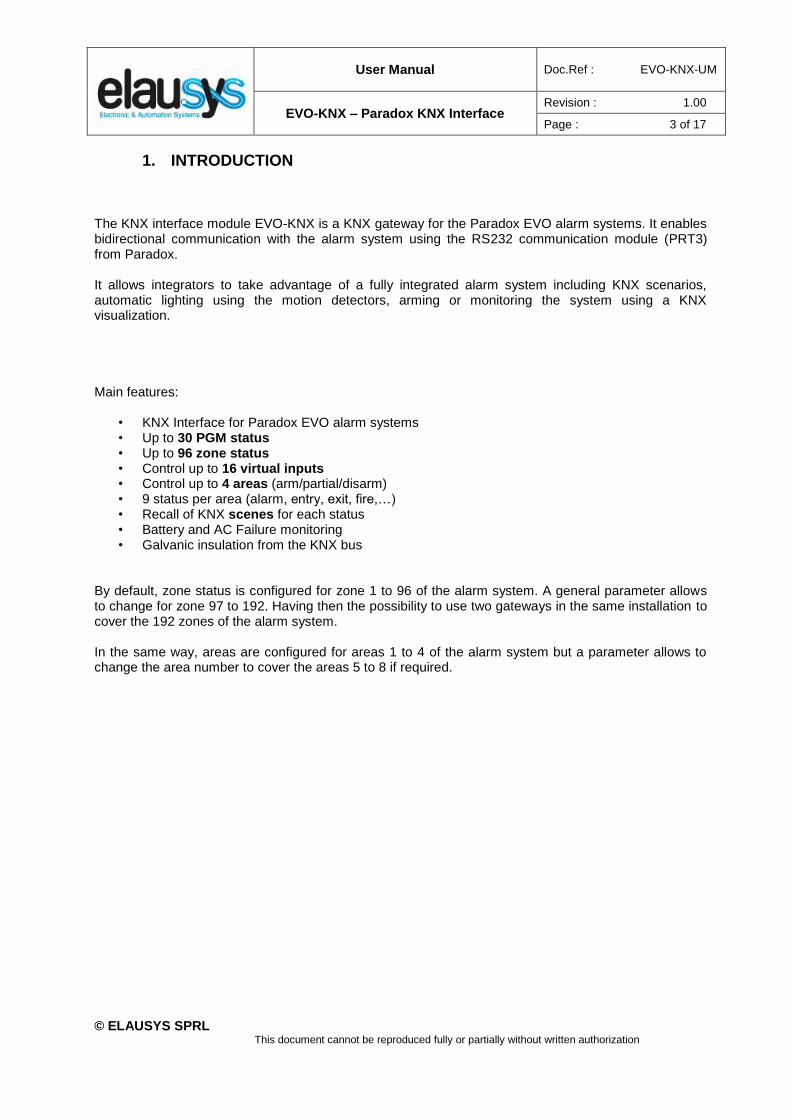
The KNX interface module EVO-KNX is a KNX gateway for the Paradox EVO alarm systems. It enables bidirectional communication with the alarm system using the RS232 communication module (PRT3) from Paradox. It allows integrators to take advantage of a fully integrated alarm system including KNX scenarios, automatic lighting using the motion detectors, arming or monitoring the system using a KNX visualization. Main features:
• KNX Interface for Paradox EVO alarm systems • Up to 30 PGM status • Up to 96 zone status • Control up to 16 virtual inputs • Control up to 4 areas (arm/partial/disarm) • 9 status per area (alarm, entry, exit, fire,…) • Recall of KNX scenes for each status • Battery and AC Failure monitoring • Galvanic insulation from the KNX bus
By default, zone status is configured for zone 1 to 96 of the alarm system. A general parameter allows to change for zone 97 to 192. Having then the possibility to use two gateways in the same installation to cover the 192 zones of the alarm system. In the same way, areas are configured for areas 1 to 4 of the alarm system but a parameter allows to change the area number to cover the areas 5 to 8 if required.

User Manual Doc.Ref : EVO-KNX-UM
EVO-KNX – Paradox KNX Interface Revision : 1.00
Page : 4 of 17
© ELAUSYS SPRL This document cannot be reproduced fully or partially without written authorization
2. OVERVIEW
2.1 USAGE & LIMITATION
This interface is intended to be used with a PARADOX EVO or DGP series alarm system. The system must be equipped with a PRT3 module for RS232 communication.
2.1 SOFTWARE
The KNX Interface is configured using the ETS tool, the free ETS Demo version can be downloaded from the website of KNX Association. The free version allows to configure up to 5 KNX modules in a project, the KNX gateway is only one module.

User Manual Doc.Ref : EVO-KNX-UM
EVO-KNX – Paradox KNX Interface Revision : 1.00
Page : 5 of 17
© ELAUSYS SPRL This document cannot be reproduced fully or partially without written authorization
2.2 CONNECTION DIAGRAM
Elausys EVO-KNX module requires an external 12VDC power supply which can be provided by the AUX power supply of the alarm system. The RS232 connection between the PRT3 and the EVO-KNX interface is made using the DB9 connector provided with this module. No additional component or wiring is required.
User Manual Doc.Ref : EVO-KNX-UM
EVO-KNX – Paradox KNX Interface Revision : 1.00
Page : 6 of 17
© ELAUSYS SPRL This document cannot be reproduced fully or partially without written authorization
3. PARAMETERS
The KNX interface parameters are defined in the “parameters” tab of the device, in the ETS project.
3.1 GENERAL SETTINGS
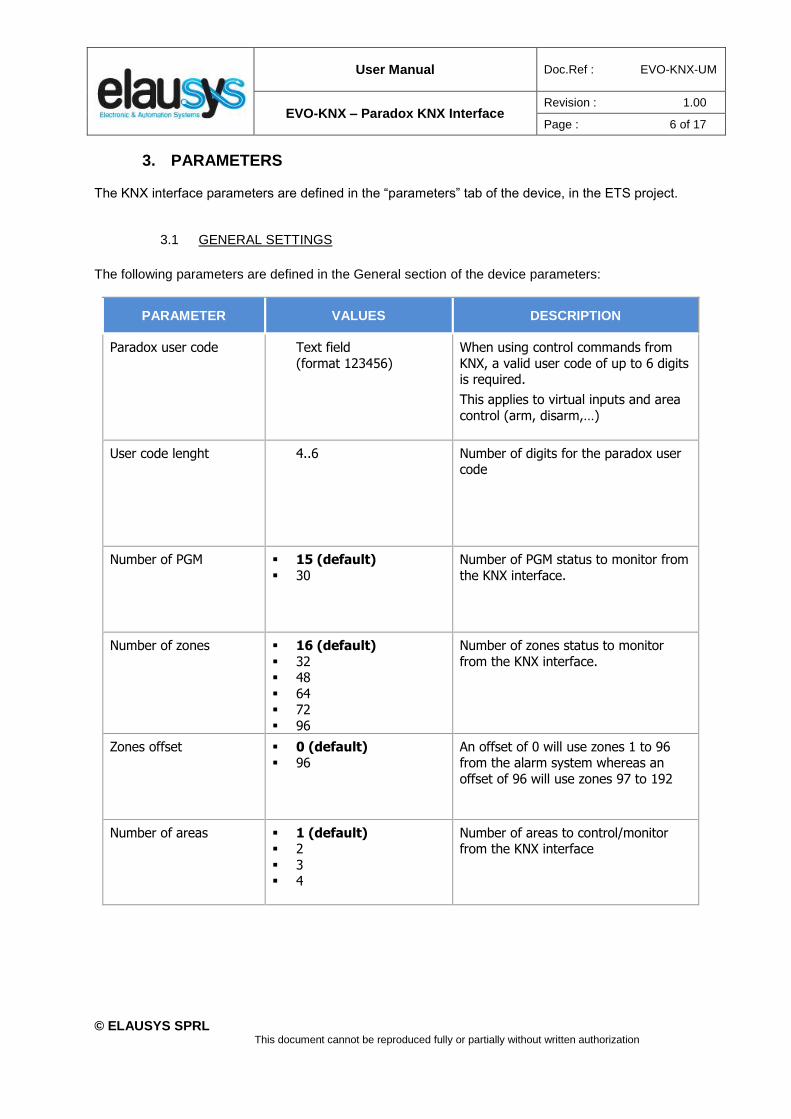
The following parameters are defined in the General section of the device parameters:
PARAMETER VALUES DESCRIPTION
Paradox user code Text field
(format 123456)
When using control commands from
KNX, a valid user code of up to 6 digits is required.
This applies to virtual inputs and area
control (arm, disarm,…)
User code lenght 4..6 Number of digits for the paradox user code
Number of PGM ▪ 15 (default)
▪ 30
Number of PGM status to monitor from
the KNX interface.
Number of zones ▪ 16 (default)
▪ 32 ▪ 48
▪ 64 ▪ 72
▪ 96
Number of zones status to monitor
from the KNX interface.
Zones offset ▪ 0 (default) ▪ 96
An offset of 0 will use zones 1 to 96 from the alarm system whereas an
offset of 96 will use zones 97 to 192
Number of areas ▪ 1 (default) ▪ 2
▪ 3 ▪ 4
Number of areas to control/monitor from the KNX interface

User Manual Doc.Ref : EVO-KNX-UM
EVO-KNX – Paradox KNX Interface Revision : 1.00
Page : 7 of 17
© ELAUSYS SPRL This document cannot be reproduced fully or partially without written authorization
3.2 PGM
Depending the general parameter “Number of PGM”, 15 or 30 PGM are listed in the group objects. The status of each PGM from the Paradox alarm system can be monitored by a Group object. The PGM is configured in the Paradox system to send status based on specific events.
There are no specific parameters for PGM.
3.3 ZONE
Depending the general parameter “Number of zones”, up to 96 zones are listed in the group objects. The status of each zone from the Paradox alarm system can be monitored by a Group object.
The general parameter “Zones offset” allow to use zones 1 to 96 from the alarm system or zones 97 to
192.
3.1 VIRTUAL INPUT
16 virtual inputs are listed in the group objects. Each virtual input can be controlled by a KNX Group object. The virtual input is configured in the Paradox system in order to trigger specific events.
A valid user code must be provided in the general parameters to allow the control of virtual inputs.
User Manual Doc.Ref : EVO-KNX-UM
EVO-KNX – Paradox KNX Interface Revision : 1.00
Page : 8 of 17
© ELAUSYS SPRL This document cannot be reproduced fully or partially without written authorization
3.2 AREA
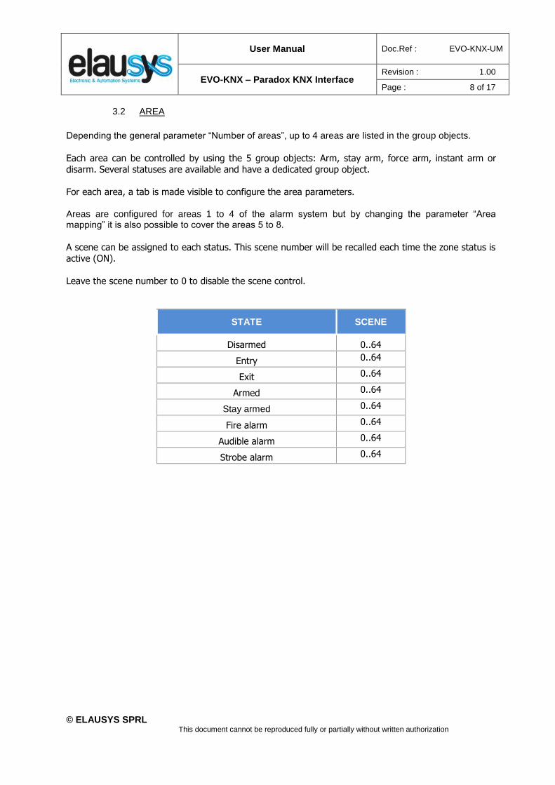
Depending the general parameter “Number of areas”, up to 4 areas are listed in the group objects.
Each area can be controlled by using the 5 group objects: Arm, stay arm, force arm, instant arm or disarm. Several statuses are available and have a dedicated group object.
For each area, a tab is made visible to configure the area parameters.
Areas are configured for areas 1 to 4 of the alarm system but by changing the parameter “Area mapping” it is also possible to cover the areas 5 to 8.
A scene can be assigned to each status. This scene number will be recalled each time the zone status is active (ON).
Leave the scene number to 0 to disable the scene control.
STATE SCENE
Disarmed 0..64
Entry 0..64
Exit 0..64
Armed 0..64
Stay armed 0..64
Fire alarm 0..64
Audible alarm 0..64
Strobe alarm 0..64
User Manual Doc.Ref : EVO-KNX-UM
EVO-KNX – Paradox KNX Interface Revision : 1.00
Page : 9 of 17
© ELAUSYS SPRL This document cannot be reproduced fully or partially without written authorization
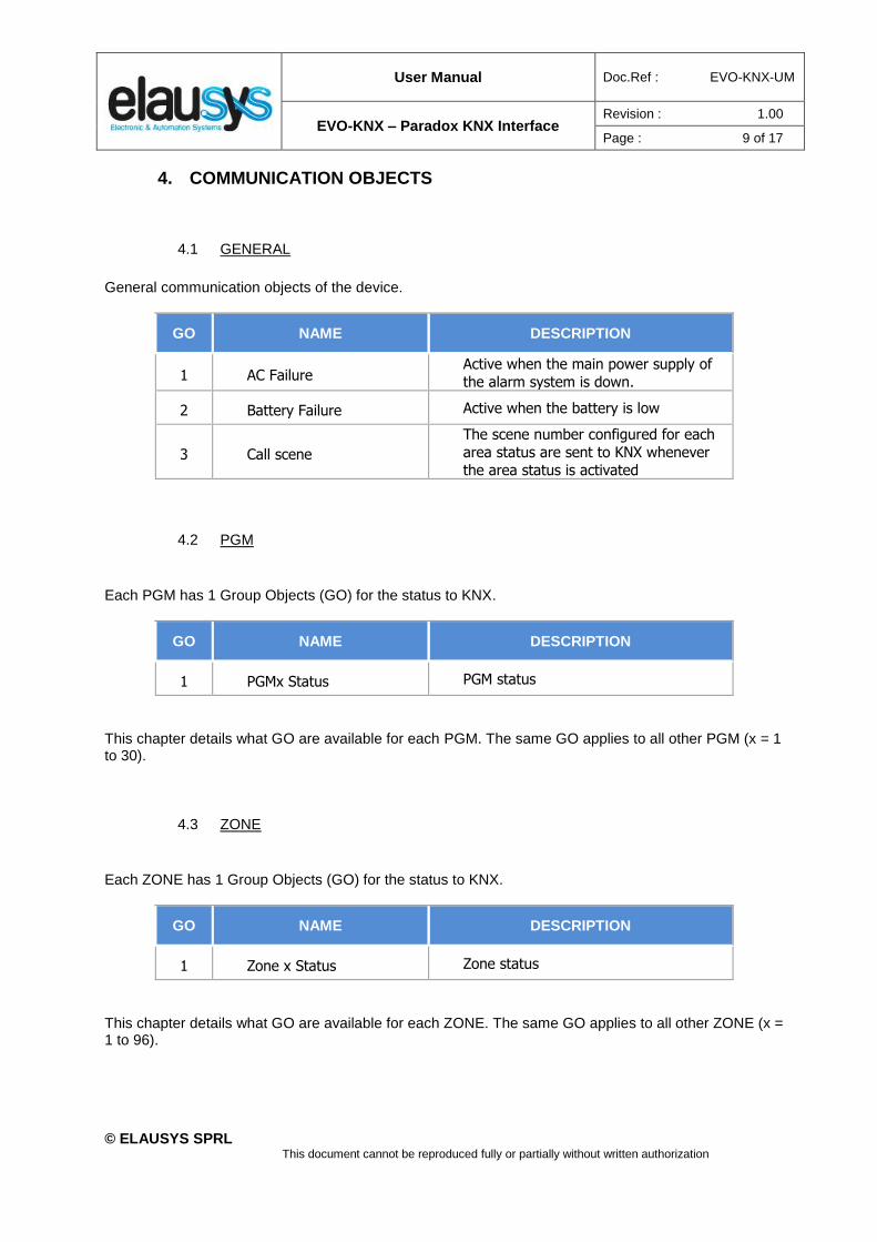
4. COMMUNICATION OBJECTS
4.1 GENERAL
General communication objects of the device.
GO NAME DESCRIPTION
1 AC Failure Active when the main power supply of
the alarm system is down.
2 Battery Failure Active when the battery is low
3 Call scene
The scene number configured for each
area status are sent to KNX whenever
the area status is activated
4.2 PGM
Each PGM has 1 Group Objects (GO) for the status to KNX.
GO NAME DESCRIPTION
1 PGMx Status PGM status
This chapter details what GO are available for each PGM. The same GO applies to all other PGM (x = 1 to 30).
4.3 ZONE
Each ZONE has 1 Group Objects (GO) for the status to KNX.
GO NAME DESCRIPTION
1 Zone x Status Zone status
This chapter details what GO are available for each ZONE. The same GO applies to all other ZONE (x = 1 to 96).
User Manual Doc.Ref : EVO-KNX-UM
EVO-KNX – Paradox KNX Interface Revision : 1.00
Page : 10 of 17
© ELAUSYS SPRL This document cannot be reproduced fully or partially without written authorization
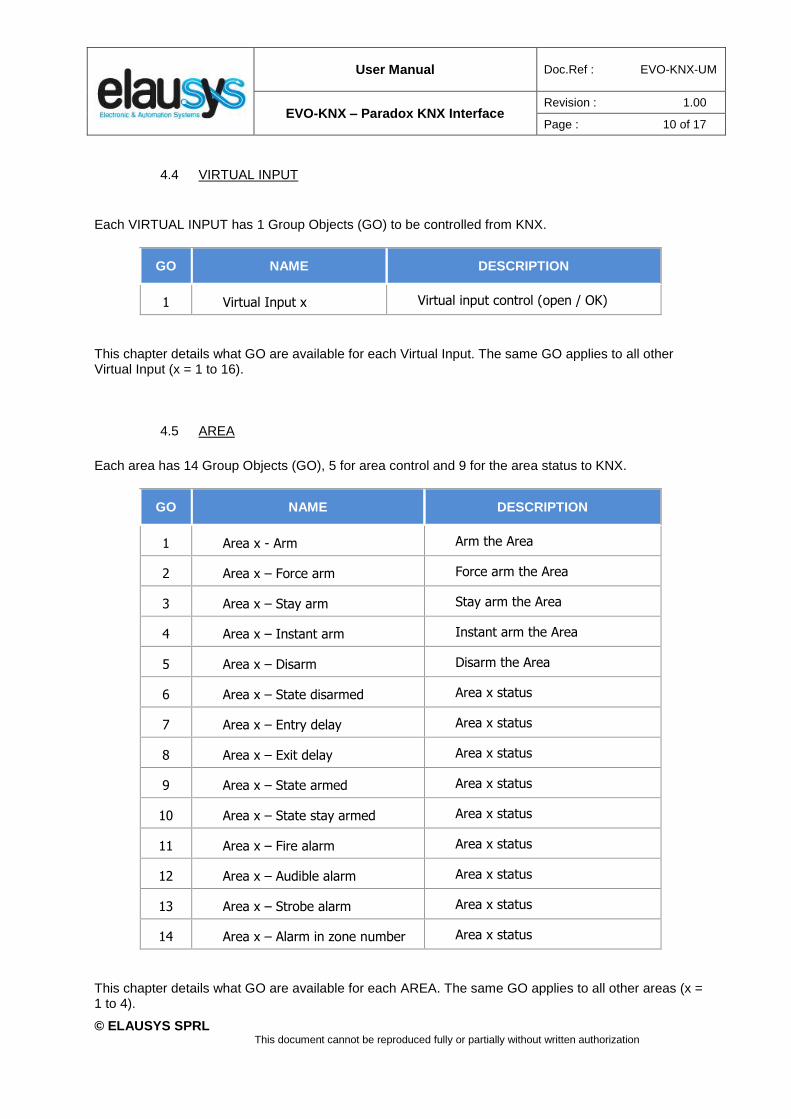
4.4 VIRTUAL INPUT
Each VIRTUAL INPUT has 1 Group Objects (GO) to be controlled from KNX.
GO NAME DESCRIPTION
1 Virtual Input x Virtual input control (open / OK)
This chapter details what GO are available for each Virtual Input. The same GO applies to all other Virtual Input (x = 1 to 16).
4.5 AREA
Each area has 14 Group Objects (GO), 5 for area control and 9 for the area status to KNX.
GO NAME DESCRIPTION
1 Area x - Arm Arm the Area
2 Area x – Force arm Force arm the Area
3 Area x – Stay arm Stay arm the Area
4 Area x – Instant arm Instant arm the Area
5 Area x – Disarm Disarm the Area
6 Area x – State disarmed Area x status
7 Area x – Entry delay Area x status
8 Area x – Exit delay Area x status
9 Area x – State armed Area x status
10 Area x – State stay armed Area x status
11 Area x – Fire alarm Area x status
12 Area x – Audible alarm Area x status
13 Area x – Strobe alarm Area x status
14 Area x – Alarm in zone number Area x status
This chapter details what GO are available for each AREA. The same GO applies to all other areas (x = 1 to 4).
User Manual Doc.Ref : EVO-KNX-UM
EVO-KNX – Paradox KNX Interface Revision : 1.00
Page : 11 of 17
© ELAUSYS SPRL This document cannot be reproduced fully or partially without written authorization
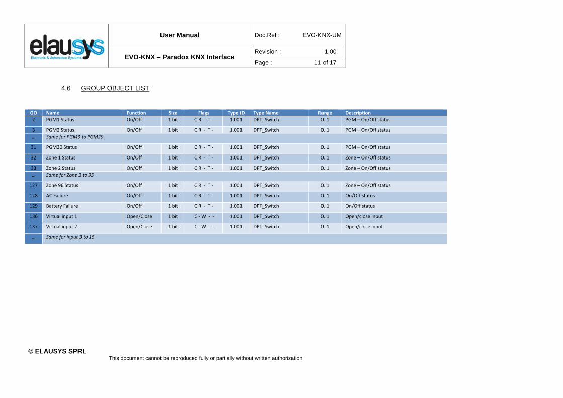
4.6 GROUP OBJECT LIST
GO Name Function Size Flags Type ID Type Name Range Description
2 PGM1 Status On/Off 1 bit C R - T - 1.001 DPT_Switch 0..1 PGM – On/Off status
3 PGM2 Status On/Off 1 bit C R - T - 1.001 DPT_Switch 0..1 PGM – On/Off status
… Same for PGM3 to PGM29
31 PGM30 Status On/Off 1 bit C R - T - 1.001 DPT_Switch 0..1 PGM – On/Off status
32 Zone 1 Status On/Off 1 bit C R - T - 1.001 DPT_Switch 0..1 Zone – On/Off status
33 Zone 2 Status On/Off 1 bit C R - T - 1.001 DPT_Switch 0..1 Zone – On/Off status
… Same for Zone 3 to 95
127 Zone 96 Status On/Off 1 bit C R - T - 1.001 DPT_Switch 0..1 Zone – On/Off status
128 AC Failure On/Off 1 bit C R - T - 1.001 DPT_Switch 0..1 On/Off status
129 Battery Failure On/Off 1 bit C R - T - 1.001 DPT_Switch 0..1 On/Off status
136 Virtual input 1 Open/Close 1 bit C - W - - 1.001 DPT_Switch 0..1 Open/close input
137 Virtual input 2 Open/Close 1 bit C - W - - 1.001 DPT_Switch 0..1 Open/close input
… Same for input 3 to 15
User Manual Doc.Ref : EVO-KNX-UM
EVO-KNX – Paradox KNX Interface Revision : 1.00
Page : 12 of 17
© ELAUSYS SPRL This document cannot be reproduced fully or partially without written authorization
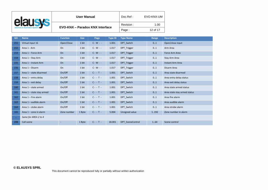
GO Name Function Size Flags Type ID Type Name Range Description
151 Virtual input 16 Open/Close 1 bit C - W - - 1.001 DPT_Switch 0..1 Open/close input
152 Area 1 - Arm On 1 bit C - W - - 1.017 DPT_Trigger 0..1 Arm Area
153 Area 1 – Force Arm On 1 bit C - W - - 1.017 DPT_Trigger 0..1 Force Arm Area
154 Area 1 – Stay Arm On 1 bit C - W - - 1.017 DPT_Trigger 0..1 Stay Arm Area
155 Area 1 – Instant Arm On 1 bit C - W - - 1.017 DPT_Trigger 0..1 Instant Arm Area
156 Area 1 – Disarm On 1 bit C - W - - 1.017 DPT_Trigger 0..1 Disarm Area
157 Area 1 – state disarmed On/Off 1 bit C - - T - 1.001 DPT_Switch 0..1 Area state disarmed
158 Area 1 – entry delay On/Off 1 bit C - - T - 1.001 DPT_Switch 0..1 Area entry delay status
159 Area 1 – exit delay On/Off 1 bit C - - T - 1.001 DPT_Switch 0..1 Area exit delay status
160 Area 1 – state armed On/Off 1 bit C - - T - 1.001 DPT_Switch 0..1 Area state armed status
161 Area 1 – state stay armed On/Off 1 bit C - - T - 1.001 DPT_Switch 0..1 Area state stay armed status
162 Area 1 – Fire alarm On/Off 1 bit C - - T - 1.001 DPT_Switch 0..1 Area fire alarm
163 Area 1 – audible alarm On/Off 1 bit C - - T - 1.001 DPT_Switch 0..1 Area audible alarm
164 Area 1 – stobe alarm On/Off 1 bit C - - T - 1.001 DPT_Switch 0..1 Area strobe alarm
165 Area 1 – zone in alarm Zone number 1 Byte C - - T - 5.004 Unsigned value 1..192 Zone number in alarm
… Same for AREA 2 to 4
208 Call scene - 1 Byte C - - T - 18.001 DPT_SceneControl 1..64 Scene control

User Manual Doc.Ref : EVO-KNX-UM
EVO-KNX – Paradox KNX Interface Revision : 1.00
Page : 13 of 17
© ELAUSYS SPRL This document cannot be reproduced fully or partially without written authorization
5. CONFIGURATION
5.1 PHYSICAL DEVICE
ELAUSYS devices are configured using the ETS tool. You should first download and install the free version of ETS tool before you continue. The EVO-KNX Interface must be assigned a physical address on the KNX network. Assign a free address to the module, in our example we choose 1.1.50.
5.2 PARAMETERS
Once a KNX physical address is set, open the parameter tab to configure the interface. The parameters are grouped into sections: A general section and a section for each Area configured. There are no specific parameters for PGMs.
In the general section, enter a valid user code from the Paradox system to enable virtual input and area control. Select the requested number of PGM (15 or 30). Note that the Paradox system is limited to 30 PGMs. Then select the number of Areas to be controlled or monitored (up to 4).
User Manual Doc.Ref : EVO-KNX-UM
EVO-KNX – Paradox KNX Interface Revision : 1.00
Page : 14 of 17
© ELAUSYS SPRL This document cannot be reproduced fully or partially without written authorization
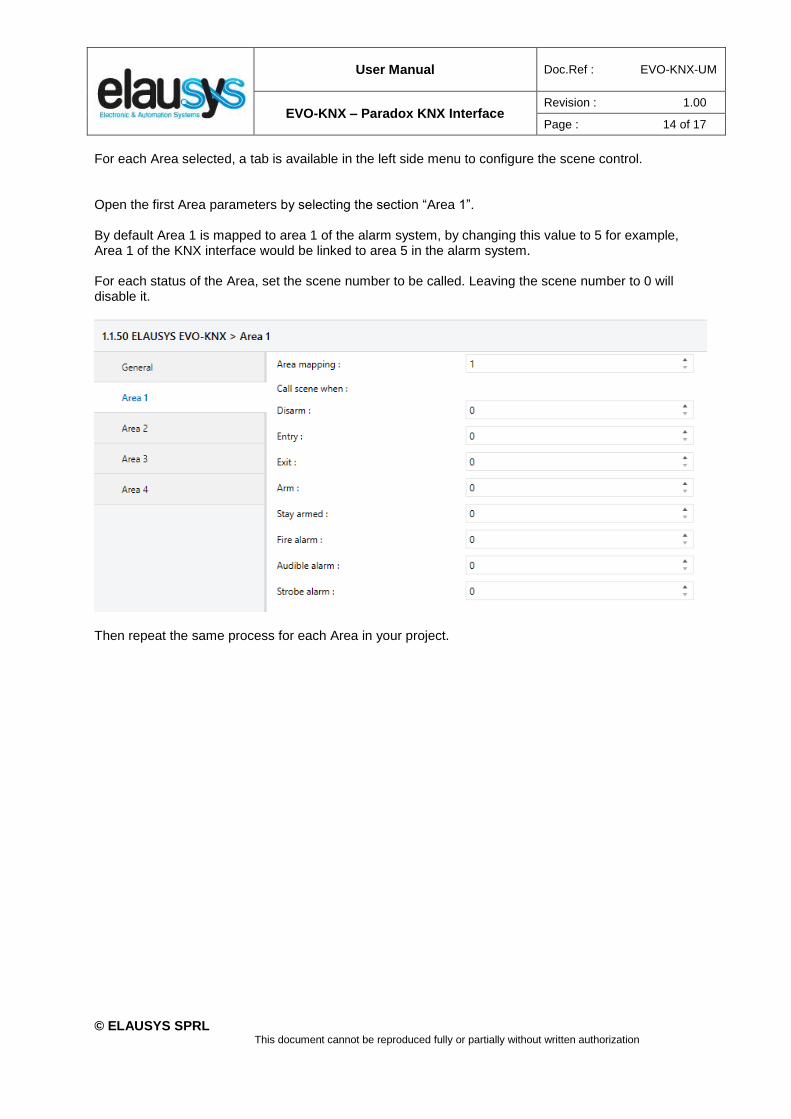
For each Area selected, a tab is available in the left side menu to configure the scene control.
Open the first Area parameters by selecting the section “Area 1”. By default Area 1 is mapped to area 1 of the alarm system, by changing this value to 5 for example, Area 1 of the KNX interface would be linked to area 5 in the alarm system. For each status of the Area, set the scene number to be called. Leaving the scene number to 0 will disable it.
Then repeat the same process for each Area in your project.
User Manual Doc.Ref : EVO-KNX-UM
EVO-KNX – Paradox KNX Interface Revision : 1.00
Page : 15 of 17
© ELAUSYS SPRL This document cannot be reproduced fully or partially without written authorization
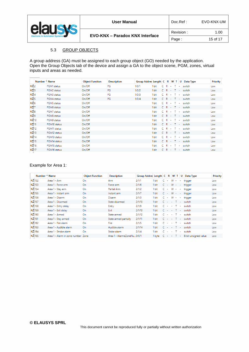
5.3 GROUP OBJECTS
A group address (GA) must be assigned to each group object (GO) needed by the application. Open the Group Objects tab of the device and assign a GA to the object scene, PGM, zones, virtual inputs and areas as needed.
Example for Area 1:
User Manual Doc.Ref : EVO-KNX-UM
EVO-KNX – Paradox KNX Interface Revision : 1.00
Page : 16 of 17
© ELAUSYS SPRL This document cannot be reproduced fully or partially without written authorization
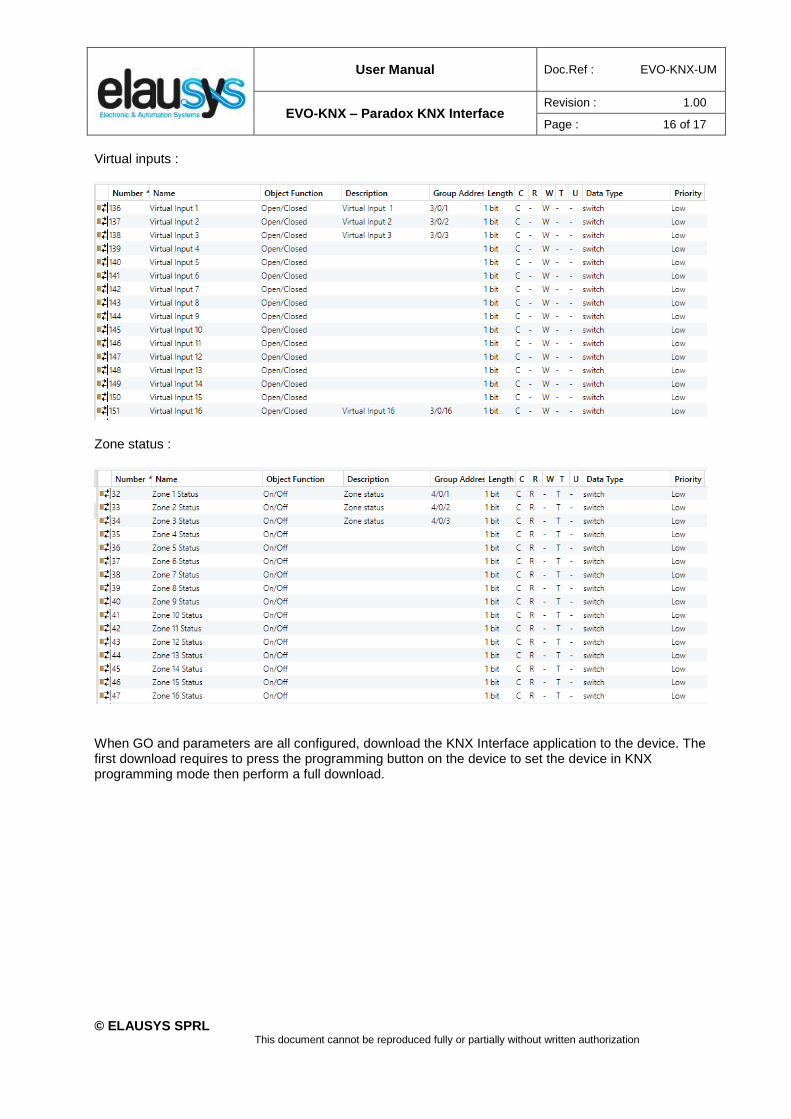
Virtual inputs :
Zone status :
When GO and parameters are all configured, download the KNX Interface application to the device. The first download requires to press the programming button on the device to set the device in KNX programming mode then perform a full download.
User Manual Doc.Ref : EVO-KNX-UM
EVO-KNX – Paradox KNX Interface Revision : 1.00
Page : 17 of 17
© ELAUSYS SPRL This document cannot be reproduced fully or partially without written authorization
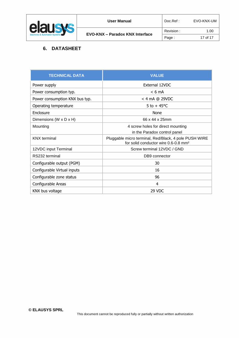
6. DATASHEET
TECHNICAL DATA VALUE
Power supply External 12VDC
Power consumption typ. < 6 mA
Power consumption KNX bus typ. < 4 mA @ 29VDC
Operating temperature 5 to + 45°C
Enclosure None
Dimensions (W x D x H) 66 x 44 x 25mm
Mounting 4 screw holes for direct mounting
in the Paradox control panel
KNX terminal Pluggable micro terminal, Red/Black, 4 pole PUSH WIRE for solid conductor wire 0.6-0.8 mm²
12VDC input Terminal Screw terminal 12VDC / GND
RS232 terminal DB9 connector
Configurable output (PGM) 30
Configurable Virtual inputs 16
Configurable zone status 96
Configurable Areas 4
KNX bus voltage 29 VDC


![KNX Association KNX Association [Official website]...KNX BBegeHMe CTaHOBRCb KNX-napTHep0M, Bbl, KaK BaHHblü KNX-HHcTaM9Top, noAHhMaeTe ce6q M CBC»O Ha KaqeCTBeHH0 ypogeHb - o Bac](https://static.fdocuments.in/doc/165x107/5f5ce7fd12687c638d19b258/knx-association-knx-association-official-website-knx-bbegehme-ctahobrcb-knx-napthep0m.jpg)