ELATION PIXEL BAR - USER MANUAL...
24
PIXEL BAR 12 / 20 / 40™ user manual ELATION | PIXEL BAR 12 / 20 / 40 ™ | user manual
Transcript of ELATION PIXEL BAR - USER MANUAL...
PIXEL BAR 12 / 20 / 40™
user manual
ELA
TION
| PIX
EL BAR 12 / 20 / 40 ™
| u
ser m
an
ua
l

w w w . e l a t i o n l i g h t i n g . c o m
2 PIXEL BAR 12 / 20 / 40™ User Manual
©2015 ELATION PROFESSIONAL all rights reserved. Information, specifications, diagrams, images, and instructions herein are subject to change without notice. ELATION PROFESSIONAL logo and identifying product names and numbers herein are trademarks of ELATION PROFESSIONAL. Copyright protection claimed includes all forms and matters of copyrightable materials and information now allowed by statutory or judicial law or hereinafter granted. Product names used in this document may be trademarks or registered trademarks of their respective companies and are hereby acknowledged. All non-ELATION brands and product names are trademarks or registered trademarks of their respective companies. ELATION PROFESSIONAL and all affiliated companies hereby disclaim any and all liabilities for property, equipment, building, and electrical damages, injuries to any persons, and direct or indirect economic loss associated with the use or reliance of any information contained within this document, and/or as a result of the improper, unsafe, insufficient and negligent assembly, installation, rigging, and operation of this product.
Elation Professional USA | 6122 S. Eastern Ave. | Los Angeles, CA. 90040
323-582-3322 | 323-832-9142 fax | www.elationlighting.com | [email protected]
Elation Professional B.V. | Junostraat 2 | 6468 EW Kerkrade, The Netherlands
+31 45 546 85 66 | +31 45 546 85 96 fax | www.elationlighting.eu | [email protected]
D O C U M E N T V E R S I O N
Please check www.elationlighting.com for the latest revision/update of this manual.
Date Document
Version
DMX Channel Modes Notes
11/04/15 1 12* / 20* / 40* Updated manual format, added tube lens
installation section.
07/22/16 2 12* / 20* / 40* Updated system configuration diagram.
12/22/16 2.1 12* / 20* / 40*
Added notice regarding maximum CAT5e cable
length (98.4 ft / 30m MAX). Updated system
configuration diagram.
*DMX Channel Modes are specific to the PIXEL BAR™ model (12, 20, 40).

w w w . e l a t i o n l i g h t i n g . c o m
3 PIXEL BAR 12 / 20 / 40™ User Manual
C O N T E N T S
General Information 4
Warranty 6
Safety Instructions 7
General Guidelines 8
Fixture Overview 9
Fixture Installation 10
Optional Tube Lens Installation 13
System Configuration Guide 14
DMX Channel Functions And Values 15
Cleaning and Maintenance 18
Technical Specifications 19
Optional Accessories 23

w w w . e l a t i o n l i g h t i n g . c o m
4 PIXEL BAR 12 / 20 / 40™ User Manual
G E N E R A L I N F O R M A T I O N
INTRODUCTION
Congratulations, you have just purchased one of the most innovative and
reliable lighting fixtures on the market today! The fixture has been designed to
perform reliably for years when the guidelines in this booklet are followed. Please
read and understand the instructions in this manual carefully and thoroughly
before attempting to operate this unit. These instructions contain important
information regarding safety during use and maintenance.
UNPACKING
Every fixture has been thoroughly tested and has been shipped in perfect
operating condition. Carefully check the shipping carton for damage that may
have occurred during shipping. If the carton appears to be damaged, carefully
inspect your unit for damage and be sure all accessories necessary to operate
the unit have arrived intact. In the event damage has been found or parts are
missing, please contact our customer support team for further instructions. Please
do not return this unit to your dealer without first contacting customer support at
the number listed below. Please do not discard the shipping carton in the trash.
Please recycle whenever possible.
BOX CONTENTS
(1) Mounting Bracket
Manual & Warranty Card

w w w . e l a t i o n l i g h t i n g . c o m
5 PIXEL BAR 12 / 20 / 40™ User Manual
CUSTOMER SUPPORT
Elation Professional® provides a customer support line, to provide set up help and
to answer any question should you encounter problems during your set up or
initial operation. You may also visit us on the web at www.elationlighting.com for
any comments or suggestions. For service related issue please contact Elation
Professional®.
ELATION SERVICE USA - Monday - Friday 8:00am to 5:00pm PST
Voice: 323-582-3322 Fax: 323-832-9142
E-mail: [email protected]
ELATION SERVICE EUROPE - Monday - Friday 08:30 to 17:00 CET
Voice: +31 45 546 85 30 Fax: +31 45 546 85 96
E-mail: [email protected]
WARRANTY REGISTRATION
Please complete and mail in the enclosed warranty card or register online:
http://www.elationlighting.com/Login.aspx to validate your purchase. All
returned service items whether under warranty or not, must be freight pre-paid
and accompany a return authorization (R.A.) number. The R.A. number must be
clearly written on the outside of the return package. A brief description of the
problem as well as the R.A. number must also be written down on a piece of
paper and included in the shipping container. If the unit is under warranty, you
must provide a copy of your proof of purchase invoice. Items returned without a
R.A. number clearly marked on the outside of the package will be refused and
returned at customer’s expense. You may obtain a R.A. number by contacting
customer support.
I M P O R T A N T N O T I C E !
There are no user serviceable parts inside this unit. Do not attempt any repairs
yourself; doing so will void your manufactures warranty. Damages resulting from
modifications to this fixture and/or the disregard of safety and general user
instructions found in this user manual void the manufactures warranty and are
not subject to any warranty claims and/or repairs.

w w w . e l a t i o n l i g h t i n g . c o m
6 PIXEL BAR 12 / 20 / 40™ User Manual
L I M I T E D W A R R A N T Y A. Elation Professional® hereby warrants, to the original purchaser, Elation Professional® products to
be free of manufacturing defects in material and workmanship for a period of two years (730 days),
and Elation Professional® product rechargeable batteries to be free of manufacturing defects in
material and workmanship for a period of six months (180 days), from the original date of purchase.
This warranty excludes discharge lamps and all product accessories. This warranty shall be valid only
if the product is purchased within the United States of America, including possessions and territories. It
is the owner’s responsibility to establish the date and place of purchase by acceptable evidence, at
the time service is sought.
B. For warranty service, send the product only to the Elation Professional® factory. All shipping
charges must be pre-paid. If the requested repairs or service (including parts replacement) are within
the terms of this warranty, Elation Professional® will pay return shipping charges only to a designated
point within the United States. If any product is sent, it must be shipped in its original package and
packaging material. No accessories should be shipped with the product. If any accessories are
shipped with the product, Elation Professional® shall have no liability what so ever for loss and/or or
damage to any such accessories, nor for the safe return thereof.
C. This warranty is void if the product serial number and/or labels are altered or removed; if the
product is modified in any manner which Elation Professional® concludes, after inspection, affects
the reliability of the product; if the product has been repaired or serviced by anyone other than the
Elation Professional® factory unless prior written authorization was issued to purchaser by Elation
Professional®; if the product is damaged because not properly maintained as set forth in the product
instructions, guidelines and/or user manual.
D. This is not a service contract, and this warranty does not include any maintenance, cleaning or
periodic check-up. During the periods as specified above, Elation Professional® will replace
defective parts at its expense, and will absorb all expenses for warranty service and repair labor by
reason of defects in material or workmanship. The sole responsibility of Elation Professional® under
this warranty shall be limited to the repair of the product, or replacement thereof, including parts, at
the sole discretion of Elation Professional®. All products covered by this warranty were manufactured
after January 1, 1990, and bare identifying marks to that effect.
E. Elation Professional® reserves the right to make changes in design and/or performance
improvements upon its products without any obligation to include these changes in any products
theretofore manufactured.
F. No warranty, whether expressed or implied, is given or made with respect to any accessory
supplied with the products described above. Except to the extent prohibited by applicable law, all
implied warranties made by Elation Professional® in connection with this product, including
warranties of merchantability or fitness, are limited in duration to the warranty periods set forth above.
And no warranties, whether expressed or implied, including warranties of merchantability or fitness,
shall apply to this product after said periods have expired. The consumer’s and/or dealer’s sole
remedy shall be such repair or replacement as is expressly provided above; and under no
circumstances shall Elation Professional® be liable for any loss and/or damage, direct and/or
consequential, arising out of the use of, and/or the inability to use, this product.
G. This warranty is the only written warranty applicable to Elation Professional® products and
supersedes all prior warranties and written descriptions of warranty terms and conditions heretofore published.

w w w . e l a t i o n l i g h t i n g . c o m
7 PIXEL BAR 12 / 20 / 40™ User Manual
S A F E T Y I N S T R U C T I O N S
This fixture is an extremely sophisticated piece of electronic equipment. To
guarantee a smooth operation, it is important to follow the guidelines in this
manual. The manufacturer of this device will not accept responsibility for
damages resulting from the misuse of this fixture due to the disregard of the
information printed in this manual.
This device falls under PROTECTION CLASS 1. It’s essential this device be
grounded properly. Only qualified personnel should perform all electrical
connections.
I N D O O R S U S E O N L Y !
DO NOT EXPOSE FIXTURE RAIN AND MOISTURE!
UNPLUG POWER BEFORE SERVICING FIXTURE!
DO NOT PLUG FIXTURE INTO A DIMMER PACK!
NEVER TOUCH FIXTURE DURING OPERATION, AS IT MAY BE HOT!
NEVER LOOK DIRECTLY INTO THE LIGHT SOURCE!
SENSITIVE PERSONS MAY SUFFER AN EPILEPTIC SHOCK!
For proper operation, follow the Installation guidelines described in this manual.
Only qualified and certified personnel should perform installation of this fixture
and only the original rigging parts (brackets) included with this fixture should be
used for installation. Any modifications will void the original manufactures
warranty and increase the risk of damage and/or personal injury.
Never look directly into the light source of this fixture to prevent risk of injury to
your retina, which may induce blindness. Those suffering from EPILEPSY should
avoid looking directly into the light source of this unit at all times.
Always disconnect from main power source before performing any type of
service and/or cleaning procedure.
w w w . e l a t i o n l i g h t i n g . c o m
8 PIXEL BAR 12 / 20 / 40™ User Manual
G E N E R A L G U I D E L I N E S
N E V E R O P E N T H I S F I X T U R E W H I L E I N U S E !
D O N O T C O N N E C T T H I S D E V I C E T O A D I M M E R P A C K !
This fixture is a professional lighting effect designed for INDOOR / DRY LOCATIONS
ONLY on stage, in nightclubs, theatres, etc.
Please make sure there are NO FLAMMABLE MATERIALS close to the fixture while
operating, to prevent any fire hazard.
Device must be installed in a location with adequate ventilation.
Smoke fluid residue, dust and any excessive particle residue will degrade product
performance, cause overheating and damage fixture. Damages caused by
inadequate cleaning or maintenance are not covered by product warranty.
DO NOT attempt installation and/or operation without knowledge how to do so.
DO NOT permit operation by persons who are not qualified to operate this type
of fixture. Most damages are the result of operations by nonprofessionals.
Consistent operational breaks may ensure the fixture will function properly for
many years to come.
DO NOT shake fixture, avoid brute force when installing and/or operating fixture.
Always install the fixture with an appropriate safety cable. When installing the
fixture in a suspended environment, always use mounting hardware that is no less
than M10 x 25 mm, also be sure the hardware is insert in the pre-arranged screw
holes in the bracket of the fixture.
Use the original packaging and materials to transport the fixture in for service.
DO NOT TOUCH the housing bare-hand during its operation. Turn OFF the power
and allow approximately 15 minutes for the fixture to cool down before replacing
or serving.

w w w . e l a t i o n l i g h t i n g . c o m
9 PIXEL BAR 12 / 20 / 40™ User Manual
F I X T U R E O V E R V I E W
w w w . e l a t i o n l i g h t i n g . c o m
10 PIXEL BAR 12 / 20 / 40™ User Manual
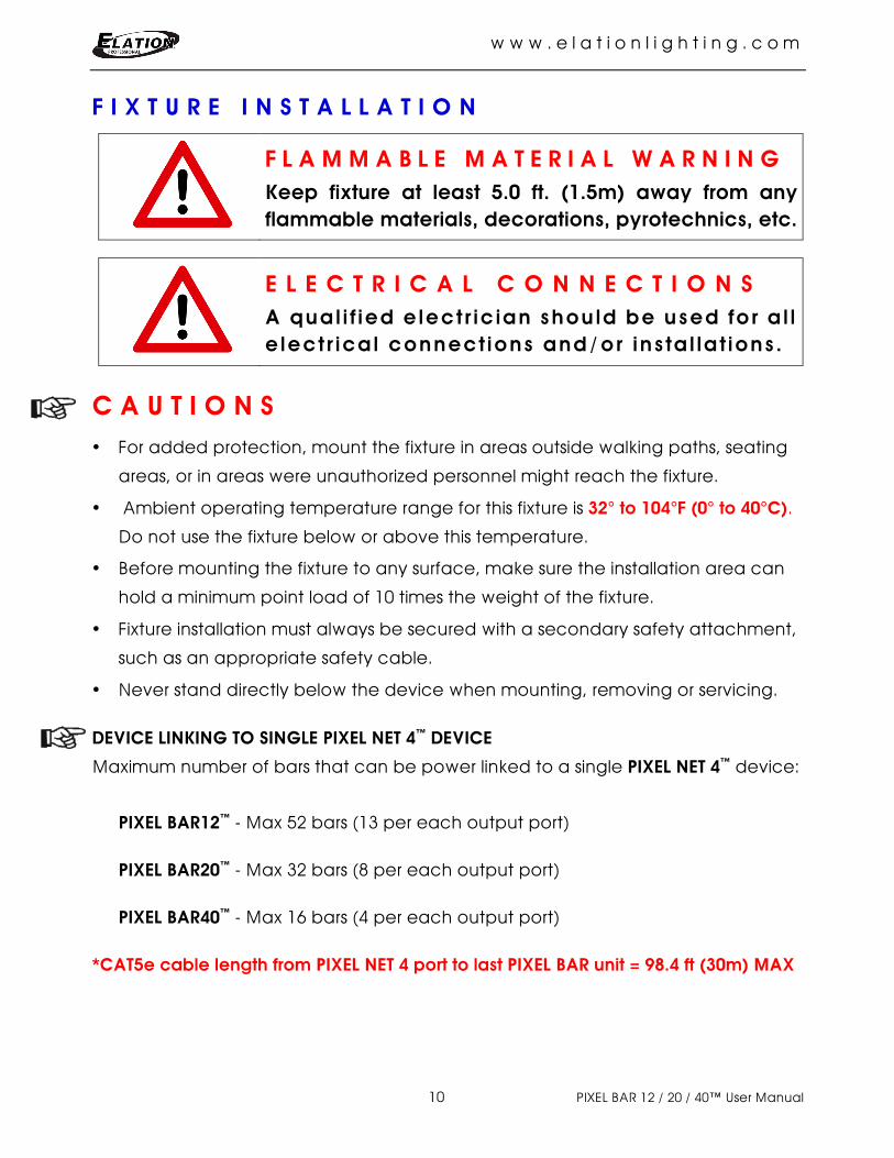
F I X T U R E I N S T A L L A T I O N
F L A M M A B L E M A T E R I A L W A R N I N G Keep fixture at least 5.0 ft. (1.5m) away from any flammable materials, decorations, pyrotechnics, etc.
E L E C T R I C A L C O N N E C T I O N S A qual i f ied electr ic ian should be used for al l e lectr ical connect ions and/or instal lat ions.
C A U T I O N S For added protection, mount the fixture in areas outside walking paths, seating
areas, or in areas were unauthorized personnel might reach the fixture.
Ambient operating temperature range for this fixture is 32° to 104°F (0° to 40°C).
Do not use the fixture below or above this temperature.
Before mounting the fixture to any surface, make sure the installation area can
hold a minimum point load of 10 times the weight of the fixture.
Fixture installation must always be secured with a secondary safety attachment,
such as an appropriate safety cable.
Never stand directly below the device when mounting, removing or servicing.
DEVICE LINKING TO SINGLE PIXEL NET 4™ DEVICE
Maximum number of bars that can be power linked to a single PIXEL NET 4™ device:
PIXEL BAR12™ - Max 52 bars (13 per each output port)
PIXEL BAR20™ - Max 32 bars (8 per each output port)
PIXEL BAR40™ - Max 16 bars (4 per each output port)
*CAT5e cable length from PIXEL NET 4 port to last PIXEL BAR unit = 98.4 ft (30m) MAX

w w w . e l a t i o n l i g h t i n g . c o m
11 PIXEL BAR 12 / 20 / 40™ User Manual
MOUNTING
The PIXEL BAR™ provides an integrated rigging bracket.
ADJUSTABLE MOUNTING BRACKET
Adjust the attached mounting bracket by loosening the thumbscrew, set the fixture
to the desired position then tighten the thumbscrew to secure the fixture position.
SURFACE MOUNTING
Use the attached mounting bracket to install the fixture to a desired surface.
RIGGING
Using an M10 bolt, secure an appropriately rated rigging clamp to the attached
mounting bracket, to install the fixture to truss.
S A F E T Y C A B L E ALWAYS USE A SAFETY CABLE WHENEVER INSTALLING THIS FIXTURE IN A SUSPENDED
ENVIRONMENT TO ENSURE THE FIXTURE WILL NOT DROP IF THE CLAMP FAILS.

w w w . e l a t i o n l i g h t i n g . c o m
12 PIXEL BAR 12 / 20 / 40™ User Manual
POWER AND DATA CONNECTIONS
Power and data are supplied to the PIXEL BARS via the input and output RJ45
connectors and CAT5e Ethernet cable using a daisy chaining method. The following
diagram indicates the pin assignment of the RJ45 connector.
Power and data are connected to the PIXEL BAR™ via the PIXEL NET 4™ device. (Sold
separately) Connect the output of the PIXEL NET 4™ device directly to the input of
the first PIXEL BAR™ Connect the output of the first fixture in the chain to the input of
the next fixture. Always connect one output with the input of the next fixture until all
fixtures are connected. The following diagram provides an example of power and
data connections.
PIXEL NET 4 First PIXEL BAR Last PIXEL BAR* *SEE NOTE BELOW
POWER LINKING
Maximum number of bars that can be power linked to a single PIXEL NET 4™ device:
PIXEL BAR12™ - Max 52 bars (13 per each output port)
PIXEL BAR20™ - Max 32 bars (8 per each output port)
PIXEL BAR40™ - Max 16 bars (4 per each output port)
*CAT5e cable length from PIXEL NET 4 port to last PIXEL BAR unit = 98.4 ft (30m) MAX

w w w . e l a t i o n l i g h t i n g . c o m
13 PIXEL BAR 12 / 20 / 40™ User Manual
T U B E L E N S I N S T A L L A T I O N An optional frost tube lens can be installed to replace the included flat frost lens.
1. Remove End Plate (4) Screws. 2. Remove Flat Frost Lens.
3. Install Frost Tube Lens. 4. Make sure Tube is installed correctly.
5. Replace End Plate and Tighten (4) Screws.

w w w . e l a t i o n l i g h t i n g . c o m
14 PIXEL BAR 12 / 20 / 40™ User Manual
S Y S T E M C O N F I G U R A T I O N G U I D E
*When connecting PIXEL NET 4 devices to a Network Switch that is also controlling multiple other lighting devices, a Gigabit Ethernet Switch that supports IGMP (Internet Group Management Protocol) is strongly suggested. Using a Gigabit Ethernet Switch that does not support IGMP can cause erratic behavior of all connected devices to the switch. Click link below for more information about IGMP.
https://en.wikipedia.org/wiki/Internet_Group_Management_Protocol

w w w . e l a t i o n l i g h t i n g . c o m
15 PIXEL BAR 12 / 20 / 40™ User Manual
D M X C H A N N E L F U N C T I O N S A N D V A L U E S ELATION© PIXEL BAR 12 / 20 / 40™
DMX Channel Values / Functions (36 / 60 / 120 DMX Channels) Specifications are subject to change without any prior written notice.
PIXEL BAR 12 PIXEL BAR 20 PIXEL BAR 40 VALUE FUNCTION
1 1 1 0-255 RED
2 2 2 0-255 GREEN
3 3 3 0-255 BLUE
4 4 4 0-255 RED
5 5 5 0-255 GREEN
6 6 6 0-255 BLUE
7 7 7 0-255 RED
8 8 8 0-255 GREEN
9 9 9 0-255 BLUE
10 10 10 0-255 RED
11 11 11 0-255 GREEN
12 12 12 0-255 BLUE
13 13 13 0-255 RED
14 14 14 0-255 GREEN
15 15 15 0-255 BLUE
16 16 16 0-255 RED
17 17 17 0-255 GREEN
18 18 18 0-255 BLUE
19 19 19 0-255 RED
20 20 20 0-255 GREEN
21 21 21 0-255 BLUE
22 22 22 0-255 RED
23 23 23 0-255 GREEN
24 24 24 0-255 BLUE
25 25 25 0-255 RED
26 26 26 0-255 GREEN
27 27 27 0-255 BLUE
28 28 28 0-255 RED
29 29 29 0-255 GREEN
30 30 30 0-255 BLUE
31 31 31 0-255 RED
32 32 32 0-255 GREEN
33 33 33 0-255 BLUE
34 34 34 0-255 RED
35 35 35 0-255 GREEN
36 36 36 0-255 BLUE
37 37 0-255 RED
38 38 0-255 GREEN
39 39 0-255 BLUE
40 40 0-255 RED
41 41 0-255 GREEN

w w w . e l a t i o n l i g h t i n g . c o m
16 PIXEL BAR 12 / 20 / 40™ User Manual
ELATION© PIXEL BAR 12 / 20 / 40™ DMX Channel Values / Functions (36 / 60 / 120 DMX Channels) Specifications are subject to change without any prior written notice.
PIXEL BAR 12 PIXEL BAR 20 PIXEL BAR 40 VALUE FUNCTION
42 42 0-255 BLUE
43 43 0-255 RED
44 44 0-255 GREEN
45 45 0-255 BLUE
46 46 0-255 RED
47 47 0-255 GREEN
48 48 0-255 BLUE
49 49 0-255 RED
50 50 0-255 GREEN
51 51 0-255 BLUE
52 52 0-255 RED
53 53 0-255 GREEN
54 54 0-255 BLUE
55 55 0-255 RED
56 56 0-255 GREEN
57 57 0-255 BLUE
58 58 0-255 RED
59 59 0-255 GREEN
60 60 0-255 BLUE
61 0-255 RED
62 0-255 GREEN
63 0-255 BLUE
64 0-255 RED
65 0-255 GREEN
66 0-255 BLUE
67 0-255 RED
68 0-255 GREEN
69 0-255 BLUE
70 0-255 RED
71 0-255 GREEN
72 0-255 BLUE
73 0-255 RED
74 0-255 GREEN
75 0-255 BLUE
76 0-255 RED
77 0-255 GREEN
78 0-255 BLUE
79 0-255 RED
80 0-255 GREEN
81 0-255 BLUE
82 0-255 RED
83 0-255 GREEN
84 0-255 BLUE
85 0-255 RED
86 0-255 GREEN
87 0-255 BLUE
88 0-255 RED 89 0-255 GREEN 90 0-255 BLUE

w w w . e l a t i o n l i g h t i n g . c o m
17 PIXEL BAR 12 / 20 / 40™ User Manual
ELATION© PIXEL BAR 12 / 20 / 40™ DMX Channel Values / Functions (36 / 60 / 120 DMX Channels) Specifications are subject to change without any prior written notice.
PIXEL BAR 12 PIXEL BAR 20 PIXEL BAR 40 VALUE FUNCTION
91 0-255 RED
92 0-255 GREEN
93 0-255 BLUE
94 0-255 RED
95 0-255 GREEN
96 0-255 BLUE
97 0-255 RED
98 0-255 GREEN
99 0-255 BLUE
100 0-255 RED
101 0-255 GREEN
102 0-255 BLUE
103 0-255 RED
104 0-255 GREEN
105 0-255 BLUE
106 0-255 RED
107 0-255 GREEN
108 0-255 BLUE
109 0-255 RED
110 0-255 GREEN
111 0-255 BLUE
112 0-255 RED
113 0-255 GREEN
114 0-255 BLUE
115 0-255 RED
116 0-255 GREEN
117 0-255 BLUE
118 0-255 RED
119 0-255 GREEN
120 0-255 BLUE
w w w . e l a t i o n l i g h t i n g . c o m
18 PIXEL BAR 12 / 20 / 40™ User Manual
C L E A N I N G A N D M A I N T E N A N C E
C A U T I O N
Disconnect power before cleaning or maintenance.
CLEANING
Frequent cleaning is recommended to insure proper function, optimized light output,
and an extended life. The frequency of cleaning depends on the environment in
which the fixture operates: damp, smoky or particularly dirty environments can
cause greater accumulation of dirt on the fixture’s optics.
Clean the external lens surface at least every 20 days with a soft cloth to avoid
dirt/debris accumulation.
Never use alcohol, solvents, or ammonia based cleaners.
MAINTENANCE
Regular inspections are recommended to insure proper function and extended life.
There are no user serviceable parts inside this fixture, please refer all other service
issues to an authorized Elation service technician. Should you need any spare parts,
please order genuine parts from your local Elation dealer.
Please refer to the following points during routine inspections:
A detailed electric check by an approved electrical engineer every three months,
to make sure the circuit contacts are in good condition and prevent overheating.
Be sure all screws and fasteners are securely tightened at all times. Lose screws may fall
out during normal operation resulting in damage or injury as larger parts could fall.
Check for any deformations on the housing, color lenses, rigging hardware and
rigging points (ceiling, suspension, trussing). Deformations in the housing could
allow for dust to enter into the fixture. Damaged rigging points or unsecured
rigging could cause the fixture to fall and seriously injure a person(s).
Electric power supply cables must not show any damage, material fatigue or
sediments. Never remove the ground prong from the power cable.

w w w . e l a t i o n l i g h t i n g . c o m
19 PIXEL BAR 12 / 20 / 40™ User Manual
T E C H N I C A L S P E C I F I C A T I O N S
FEATURES 25mm Pixel Pitch 850 NITs / 2000Hz Refresh Rate Extruded Aluminum Housing
SOURCE Pixel Bar 12™ (12) 3-in-1 SMD LEDs Pixel Bar 20™ (20) 3-in-1 SMD LEDs Pixel Bar 40™ (40) 3-in-1 SMD LEDs
COLOR 16.7 Million Colors / 8 Bits Per Color
CONTROL / CONNECTIONS Pixel Bar 12™ - 36 DMX Channels Multiple Unit Linkable (52 per PIXEL NET 4™ device) Pixel Bar 20™ - 60 DMX Channels Multiple Unit Linkable (32 units per PIXEL NET 4™ device) Pixel Bar 40™ - 120 DMX Channels Multiple Unit Linkable (16 units per PIXEL NET 4™ device) RJ45 CAT5e Input / Output (All Models)
SIZE / WEIGHT Pixel Bar 12™ Length: 11.81” (300mm) Width: 1.5” (38.2mm) Vertical Height: 4.08” (103.6mm) Weight: 2.5 lbs. (1.12kg)
Pixel Bar 20™ Length: 19.7” (500mm) Width: 1.5” (38.2mm) Vertical Height: 4.08” (103.6mm) Weight: 3.6 lbs. (1.63kg)
Pixel Bar 40™ Length: 39.4” (1000mm) Width: 1.5” (38.2mm) Vertical Height: 4.08” (103.6mm) Weight: 5.5 lbs. (2.5kg)
ELECTRICAL / THERMAL Pixel Bar 12™ 6W Max Power Consumption Pixel Bar 20™ 10W Max Power Consumption Pixel Bar 40™ 16W Max Power Consumption DC-24V 32°F to 104°F (0°C to 40°C)
APPROVALS / RATINGS
CE | cETLus | IP20
Please Note: Specifications and improvements in the design of this unit and this manual are subject to change without any prior written notice.

w w w . e l a t i o n l i g h t i n g . c o m
20 PIXEL BAR 12 / 20 / 40™ User Manual
BEAM ANGLE
DIMENSIONAL DRAWINGS - PIXEL BAR 12
Please Note: Specifications and improvements in the design of this unit and this manual are subject to change without any prior written notice.

w w w . e l a t i o n l i g h t i n g . c o m
21 PIXEL BAR 12 / 20 / 40™ User Manual
DIMENSIONAL DRAWINGS - PIXEL BAR 20
DIMENSIONAL DRAWINGS - PIXEL BAR 40
Please Note: Specifications and improvements in the design of this unit and this manual are subject to change without any prior written notice.

w w w . e l a t i o n l i g h t i n g . c o m
22 PIXEL BAR 12 / 20 / 40™ User Manual
DIMENSIONAL DRAWINGS - Width & Vertical Height (PIXEL BAR 12 / 20 / 40)
Please Note: Specifications and improvements in the design of this unit and this manual are subject to change without any prior written notice.

w w w . e l a t i o n l i g h t i n g . c o m
23 PIXEL BAR 12 / 20 / 40™ User Manual
O P T I O N A L A C C E S S O R I E S ORDER CODE ITEM NARROW CLAMP Heavy Duty 2” Wrap Around Pro Clamp PIX037 PIXEL BAR 12™ PIX167 PIXEL BAR 12™ TUBE LENS PIX025 PIXEL BAR 20™ PIX155 PIXEL BAR 20™ TUBE LENS PIX001 PIXEL BAR 40™ PIX142 PIXEL BAR 40™ TUBE LENS PIX013 Pixel Net 4™ ArtNet to DMX Driver