
Elation Led Manager Quick Start Manual
2
LED Manager 2 1 Quick Start Manual Please install LED Manager 2010 from the “.exe” file that is provided in the set up CD. After installing & launching the software proceed to “Hardware Settings” from the “Settings” menu bar. Once in “Hardware Settings” a window will open that will require an alphabetic password “Elation” then a second window will appear witch requires a numeric password “888888” Once in “Advanced Hardware Setup” proceed to “Receiving Card” and load the “V9-P7.62.sub” file that was provided on the elation set up CD. After the file has been loaded please click on “Send to RV Card” and finally “Save to RV Card”. A confirmation window will appear indicating that the file has been sent successfully.
-
Upload
arnel-banaga -
Category
Documents
-
view
227 -
download
0
Transcript of Elation Led Manager Quick Start Manual
8/18/2019 Elation Led Manager Quick Start Manual
http://slidepdf.com/reader/full/elation-led-manager-quick-start-manual 1/2
LED Manager 2 1 Quick Start Manual
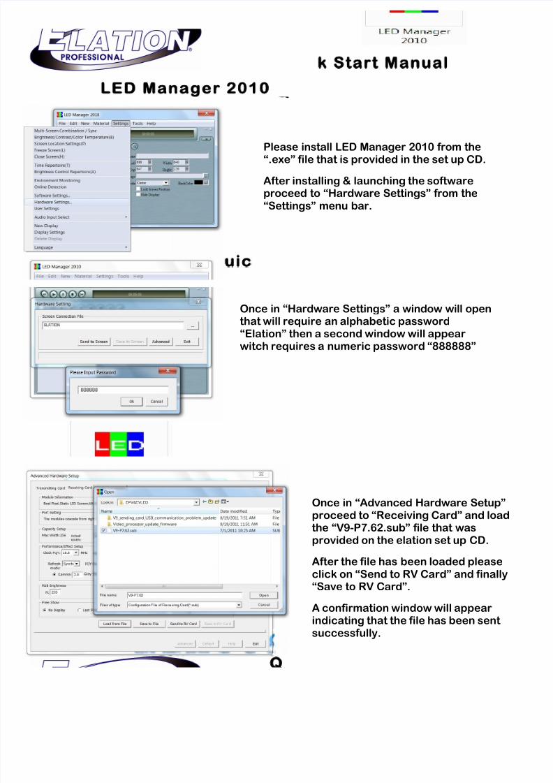
Please install LED Manager 2010 from the“.exe” file that is provided in the set up CD.
After installing & launching the softwareproceed to “Hardware Settings” from the“Settings” menu bar.
Once in “Hardware Settings” a window will openthat will require an alphabetic password“Elation” then a second window will appearwitch requires a numeric password “888888”
Once in “Advanced Hardware Setup”proceed to “Receiving Card” and loadthe “V9-P7.62.sub” file that wasprovided on the elation set up CD.
After the file has been loaded pleaseclick on “Send to RV Card” and finally“Save to RV Card”.
A confirmation window will appearindicating that the file has been sentsuccessfully.
8/18/2019 Elation Led Manager Quick Start Manual
http://slidepdf.com/reader/full/elation-led-manager-quick-start-manual 2/2
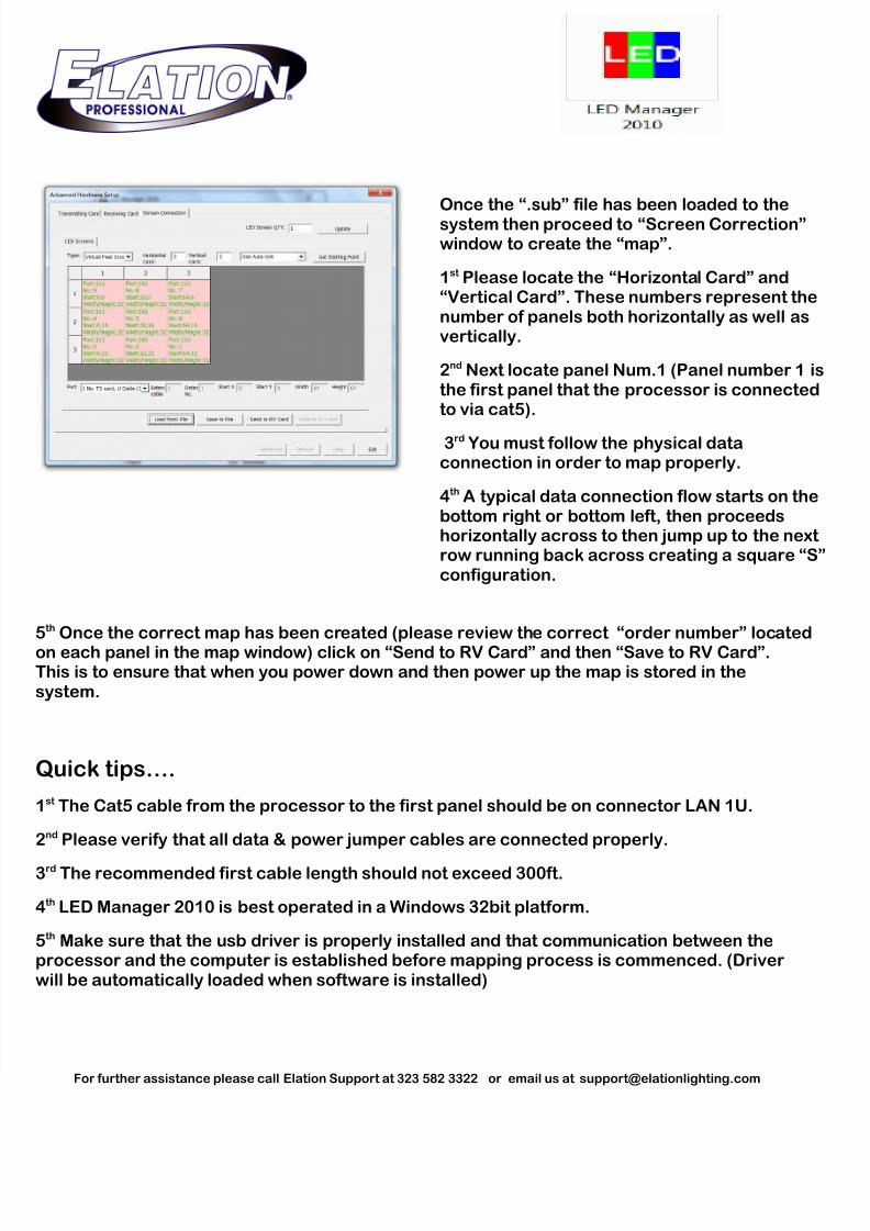
5th Once the correct map has been created (please review the correct “order number” located
on each panel in the map window) click on “Send to RV Card” and then “Save to RV Card”.This is to ensure that when you power down and then power up the map is stored in thesystem.
Quick tips….
1st The Cat5 cable from the processor to the first panel should be on connector LAN 1U.
2nd Please verify that all data & power jumper cables are connected properly.
3rd The recommended first cable length should not exceed 300ft.
4th LED Manager 2010 is best operated in a Windows 32bit platform.
5th Make sure that the usb driver is properly installed and that communication between theprocessor and the computer is established before mapping process is commenced. (Driverwill be automatically loaded when software is installed)
For further assistance please call Elation Support at 323 582 3322 or email us at [email protected]
Once the “.sub” file has been loaded to thesystem then proceed to “Screen Correction”window to create the “map”.
1st Please locate the “Horizontal Card” and“Vertical Card”. These numbers represent thenumber of panels both horizontally as well asvertically.
2nd Next locate panel Num.1 (Panel number 1 ithe first panel that the processor is connectedto via cat5).
3rd You must follow the physical dataconnection in order to map properly.
4th A typical data connection flow starts on thebottom right or bottom left, then proceedshorizontally across to then jump up to the nextrow running back across creating a square “Sconfiguration.