Elastica of sandwich panels with a transversely flexible ... · Elastica of sandwich panels with a...
17
Elastica of sandwich panels with a transversely flexible core—A high-order theory approach Yeoshua Frostig * ,1 Technion—Israel Institute of Technology, Faculty of Civil and Environmental Engineering, Haifa 32000, Israel article info Article history: Received 3 February 2008 Received in revised form 27 April 2008 Available online 22 May 2008 Keywords: Sandwich panels Elastica Compliant core Buckling Post-buckling abstract The elastica behavior of an extensional sandwich panel with a ‘‘soft” core when subjected to in-plane compressive loads is presented and it is compared with the response of its extensional equivalent single layer (ESL) with shear deformations model. The field equa- tions along with the appropriate boundary conditions for the sandwich and the ESL panels have been derived through a variational approach following the High-order SAndwich Panel Theory (HSAPT) approach that takes into account the vertical flexibility of the core. The governing equations include the effects of the extension of the mid-surfaces of the face sheets of the sandwich panel or the mid-plane of the ESL model which the classical elastica approach misses. The results of the elastica response of a clamped-simply-supported sand- wich panel and its ESL counterpart are presented and compared. They include the response along the panel, deformed shapes and equilibrium curves of in-plane loads versus struc- tural quantities such as displacements and internal stress resultants and stresses. These results reveal that the predicted buckling load of the ESL panel is larger than that of the sandwich panel and that deep in the non-linear range the upper face sheet wrinkles with increasing overall and edge displacements and a release of the load. Hence, the use of an equivalent single layer panel especially when a sandwich panel with a compliant core is considered may lead to unsafe and unreliable predictions when large displacements and large rotations are considered. Ó 2008 Elsevier Ltd. All rights reserved. 1. Introduction Modern sandwich panels, which consist of two face sheets and a compliant low strength compressible core, are used in a large variety of applications within the aerospace, naval and transportation industries. In order to exploit their structural potential and to define their safety their non-linear response that is based on large displacements and large rotations, i.e. elastica, is required. A typical sandwich panel is a layered structure that consists of face sheets made of metal or laminated composite and a core that is made of either metallic or low strength compressible honeycomb or foam. As a result of the core flexibility and compressibility, the shape of the panel is not preserved under deformation along with distortions of its section plane. In general, the approaches considered for the analysis of sandwich panels can be gathered in two major categories. In the first one the actual layered panel is replaced by an equivalent one with a single layer, denoted by ESL (equivalent single layer) with equivalent properties, see for example Mindlin first-order theory (FOSDT) (1951), and Reddy’s high-order theo- ries (1984) and others. In the second category, denoted also as the classical approach, the layered configuration is assume to 0020-7683/$ - see front matter Ó 2008 Elsevier Ltd. All rights reserved. doi:10.1016/j.ijsolstr.2008.05.007 * Tel./fax: +972 4 8293046. E-mail address: [email protected] 1 Professor of Sturctural Engineering, Ashtrom Engineering Company Chair in Civil Engineering, International Journal of Solids and Structures 46 (2009) 2043–2059 Contents lists available at ScienceDirect International Journal of Solids and Structures journal homepage: www.elsevier.com/locate/ijsolstr
Transcript of Elastica of sandwich panels with a transversely flexible ... · Elastica of sandwich panels with a...

International Journal of Solids and Structures 46 (2009) 2043–2059
Contents lists available at ScienceDirect
International Journal of Solids and Structures
journal homepage: www.elsevier .com/locate / i jsols t r
Elastica of sandwich panels with a transversely flexible core—Ahigh-order theory approach
Yeoshua Frostig *,1
Technion—Israel Institute of Technology, Faculty of Civil and Environmental Engineering, Haifa 32000, Israel
a r t i c l e i n f o a b s t r a c t
Article history:Received 3 February 2008Received in revised form 27 April 2008Available online 22 May 2008
Keywords:Sandwich panelsElasticaCompliant coreBucklingPost-buckling
0020-7683/$ - see front matter � 2008 Elsevier Ltddoi:10.1016/j.ijsolstr.2008.05.007
* Tel./fax: +972 4 8293046.E-mail address: [email protected]
1 Professor of Sturctural Engineering, Ashtrom Eng
The elastica behavior of an extensional sandwich panel with a ‘‘soft” core when subjectedto in-plane compressive loads is presented and it is compared with the response of itsextensional equivalent single layer (ESL) with shear deformations model. The field equa-tions along with the appropriate boundary conditions for the sandwich and the ESL panelshave been derived through a variational approach following the High-order SAndwichPanel Theory (HSAPT) approach that takes into account the vertical flexibility of the core.The governing equations include the effects of the extension of the mid-surfaces of the facesheets of the sandwich panel or the mid-plane of the ESL model which the classical elasticaapproach misses. The results of the elastica response of a clamped-simply-supported sand-wich panel and its ESL counterpart are presented and compared. They include the responsealong the panel, deformed shapes and equilibrium curves of in-plane loads versus struc-tural quantities such as displacements and internal stress resultants and stresses. Theseresults reveal that the predicted buckling load of the ESL panel is larger than that of thesandwich panel and that deep in the non-linear range the upper face sheet wrinkles withincreasing overall and edge displacements and a release of the load. Hence, the use of anequivalent single layer panel especially when a sandwich panel with a compliant core isconsidered may lead to unsafe and unreliable predictions when large displacements andlarge rotations are considered.
� 2008 Elsevier Ltd. All rights reserved.
1. Introduction
Modern sandwich panels, which consist of two face sheets and a compliant low strength compressible core, are used in alarge variety of applications within the aerospace, naval and transportation industries. In order to exploit their structuralpotential and to define their safety their non-linear response that is based on large displacements and large rotations, i.e.elastica, is required. A typical sandwich panel is a layered structure that consists of face sheets made of metal or laminatedcomposite and a core that is made of either metallic or low strength compressible honeycomb or foam. As a result of the coreflexibility and compressibility, the shape of the panel is not preserved under deformation along with distortions of its sectionplane.
In general, the approaches considered for the analysis of sandwich panels can be gathered in two major categories. In thefirst one the actual layered panel is replaced by an equivalent one with a single layer, denoted by ESL (equivalent singlelayer) with equivalent properties, see for example Mindlin first-order theory (FOSDT) (1951), and Reddy’s high-order theo-ries (1984) and others. In the second category, denoted also as the classical approach, the layered configuration is assume to
. All rights reserved.
ineering Company Chair in Civil Engineering,

2044 Y. Frostig / International Journal of Solids and Structures 46 (2009) 2043–2059
consist of a core that is incompressible and is infinitely stiff in the vertical direction, see textbooks by Allen (1969), Plantema(1966), Zenkert (1995) and Vinson (1999). A different approach where the vertical flexibility of the core is considered alongwith the localized effects involved has been considered by the author and many others using the High-order SAndwich PanelTheory (HSAPT) approach, see Frostig et al. (1992). It has been applied successfully to a large number of linear and non-linearanalyses such as: debonding of face sheets, see Frostig (1992), buckling of sandwich panels, see Frostig and Baruch (1993)and Frostig (1998), non-linear behavior of sandwich panels with rigid and non-rigid interfaces including branching behavior,see Sokolinsky and Frostig (2000), comparisons of the HSAPT model elasticity and FE results see Swanson (1999), indentationresistance analysis using the HSAPT model, see Petras and Sutcliffe (1999, 2000), an experimental and analytical study, seeSokolinsky et al. (2003), non-linear response of sandwich panels, see Frostig and Thomsen (2005), and non-linear response ofsandwich shells, see Hohe and Librescu (2003).
Elastica of inextensible beams made of a solid section had attracted the attention of many researchers for many yearsstarting with the pioneering works of Euler and Lagrange, see Dym and Shames (1973), using closed-form solutions withthe aid of elliptic integrals. The elastica response of bars with various sections, particular type of loadings and boundary con-ditions appears in a numerous number of research works and with various type of solution approaches and to mention a few:Wang (1997) dealt with elastica of a clamped-simply-supported beam using perturbation, asymptotic and numerical meth-od; Chucheepsakul and Huang (1997) used FE approach to analyze a beam with a point load between the supports; Ligamovand Ratrout (1999) have analyzed the large displacements of a superconducting cable with fluids inside; temperature effectshave been investigated by Coffin and Bloom (1999), Vinogradov and Derrick (2000) investigated the elastica of a bar made ofasymmetric laminates layers; Lee (2001, 2002) dealt with a cantilever under distributed and a concentrated load with a lin-ear and non-linear material and Madhusudan et al. (2003) analyzed a cantilever with a variable cross section. In general, theanalyses of the elastica of rods, mentioned above, use the equilibrium equations which have been derived through equilib-rium of the deformed shape of a differential segment of the rod.
A variational approach that uses Reissners’ kinematic relations (see Reissner (1972)), has been considered by Flajs et al.(2003) that used Lagrange multiplier to impose the kinematic relations as constraints and by Pak and Stauffer (1993).
The problem of large displacements and large rotations of unidirectional sandwich panels has been considered by a verysmall number of researchers assuming that the layered sandwich panel can be replaced by an equivalent single layer withshear deformation, see Huang and Kardomateas (2002) and Bazant and Beghini (2006).
The brief literature survey reveals that the elastica response of sandwich panels made of two face sheets and a compliantcore where the vertical flexibility of the core is considered is missing. The approach used here is based on the HSAPT modelalong with the variational approach. The assumptions adopted follow the ‘‘classical” assumptions for sandwich structureswith compliant cores: the face sheets possess in-plane and bending rigidities; the face sheets and the core material are as-sumed be linear elastic; the face sheets include shear deformations following the FOSDT approach and they undergo largedisplacements and large rotations with moderate strains; the core is considered as a 2D linear elastic continuum that under-goes large rigid body displacements (due to its bond to the adjacent face sheets), but with kinematic relations that corre-spond to those of small deformations, where the core height may change during deformation and its section plane doesnot remain plane after deformation; the core possesses only shear and vertical normal stiffness, whereas the in-plane (lon-gitudinal) normal stiffness is neglected; full bond is assumed between the face sheets and the core; and the mechanical loadsare applied to the face sheets only; and it is also assumed that the sandwich panel does not looses its integrity as a result ofthe large deformations and the associated stresses are within the strength capacity of the components of the panel.
The paper consists of a mathematical formulation and a numerical part. In the mathematical formulation, the elasticafield and governing equations along with the appropriate boundary, of a sandwich panel that follows the HSAPT modeland its ESL counterpart are derived using a variational approach. In the numerical part the elastica response of a real sand-wich panel made of three layers and its equivalent single layer (ESL) model with shear deformations are presented. A com-parison between the two models is presented and discussed. Finally a summary is included and conclusions are drawn.
2. Mathematical formulation
The mathematical formulation consists of two parts. The first part deals with a real sandwich panel using the HSAPT ap-proach where the shear deformations of the face sheets are considered. The second part is based on the first part and definesthe equations for an equivalent single layer sandwich panel with shear deformations. The derivation of the governing fieldequations of the layered sandwich panel with their appropriate boundary conditions for the face sheets and the core and thestress and the deformations field of the core in a closed-form is presented next.
2.1. Sandwich panel—HSAPT model
The governing equations and the boundary conditions are derived via the variational principle imposed on the totalpotential energy, as follows:
dðU þ VÞ ¼ 0 ð1Þ
where U and V are the internal and the external potential energy, respectively, and d denotes the variation operator.

Y. Frostig / International Journal of Solids and Structures 46 (2009) 2043–2059 2045
The first variation of the internal potential energy in terms of stresses and strains reads:
dt
db
c
n
n
Fig. 1. Ddirectio
dU ¼Z
vt
ðrsstdesst þ ssntdcsntÞdV þZ
vb
ðrssbdessb þ ssnbdcsnbÞdV þZ
vc
ðsxzdcsz þ dzzrezzÞdV þ dUk ð2Þ
where rssj and essj (j = t,b) are the in-plane normal stresses and ssnj and csnj (j = t,b) are the vertical shear stress and shear angleof the face sheets (in local coordinate directions); txz and csz are the vertical shear stresses strains in the core; rzz and ezz arethe normal stresses and strains in the vertical direction of the core (global coordinate directions); Vk(k = t,b,c) are the volumeof the upper and lower face sheets and the core, respectively; dV denotes the volume of a differential segment and dUk is thecontribution of imposed conditions, see Eq. (8) ahead.
dV ¼ �Z L
0ðnxtduot þ qztdwt þmtdwt;s þ nxbduob þ qzbdwb þmbdwb;sÞds
� �
�XNC
i¼1
Z L
0ðNxetiduot þ Pzetidwt þMetidwt;s þ Nxebiduob þ Pzebidwb þMebidwb;sÞddðs� siÞds
� � !ð3Þ
where nxj, qzj and mj (j = t,b) are the in-plane and vertical distributed loads (in the global coordinates) and the bending mo-ment distributed loads, respectively; Nxeji, Pzeki and Meji (j = t,b) are external concentrated loads in the in-plane, vertical direc-tion (global coordinates) and the concentrated moment respectively exerted at s = si; NC denotes the number of concentratedloads; dd(s � si) are the delta of Dirac function; uoj, wj and wj,s (j = t,b) are the in-plane and the vertical displacement (in globalcoordinates directions) and the rotation of each face sheets, respectively and s is the longitudinal coordinate. Geometry andsign convention of stresses, displacements, and loads appear in Fig. 1.
The displacements pattern of the face sheets takes into account the shear deformations following the FOSDT approach,see Mindlin (1951), and they read (j = t,b):
ujðs; zjÞ ¼ uojðsÞ � zjWjðsÞ ð4Þ
where zj are the vertical coordinates of each face sheet independently and they are measured downwards from the centroidof each face sheet (see Fig. 1a); uoj are the in-plane displacements at the centroid of the face sheets and Wj(s) is the rotationangle of the section plane of the face sheets and is related to the shear angle, cj(s) by the following expression:
cjðsÞ ¼ �WjðsÞ þdds
wjðsÞ ð5Þ
UpperFace
Face
Msst+Msst,sdsVsntNsst
Vsnt+Vsnt,sds
Msst
τ(s,zc)cbw (τ+τ,sds)cbw
σzz(s,zc=0)bwds
τ(s,zc=0)bwds
ds
ds
ψt+ψt,sds
τ(s,zc=0)bwds
τ(s,zc=c)bwdsσzz(s,zc=c)bwds
Mssb+Mssb,sds
VsnbNssb
Vsnb+Vsnb,sdsMssb
Nssb+Nssb,sds
Core
τxzc(s,zc=c)bwds
Nsst+Nsst,sds
ψt
ψb,s+ψb,sdsψb
c.g
ac.g
qzt Pzeti
dt/2
db/2
s,uotzt,wt
s,uob
zb,wb
zc,wc
s,uc
Lower
b
xt
mt
qzb mb
Nxeti
Meti
Pzebi Mebi
s=si
Nxebixb
c
UpperFace
Face
Msst+Msst,sdsλt1
Msst
σzz(s,zc=0)bwds
ds
ds
ψt+ψt,sds
σzz(s,zc=c)bwds
Mssb+Mssb,sds
Mssb
Core
τxzc(s,zc=c)bwds
λt1+λt1,sds
ψt
ψb,s+ψb,sdsψb
Lower
d
λt2
λt2+λt2,sds
λb1
λb1+λb1,sds
λb2
λb2+λb2,sds
τ(s,zc=0)bwds
τ(s,zc)cbw (τ+τ,sds)cbw
τ(s,zc=0)bwds
τ(s,zc=c)bwds
imensions and signs conventions of a typical sandwich panel. (a) Geometry; (b) loads at face sheets. Internal stress resultants in (c) local coordinatens and (d) in global coordinate directions.

2046 Y. Frostig / International Journal of Solids and Structures 46 (2009) 2043–2059
Notice that the shear strain is independent of the vertical coordinate of the face sheet following the FOSDT computationalmodel. In addition when the shear deformation is neglected the slope of the section plane equals WjðsÞ ¼ d
ds wjðsÞ.The kinematic relations of large displacements and large rotations of the face sheets with shear deformations read:
essjðs; zÞ ¼ eojðsÞ � zjdds
WjðsÞ� �
ð6Þ
where eoj(s) is the mid-plane strain and cj (s) is the shear angle of the face sheets. They can be defined using the displace-ments pattern that appears in Fig. 2 for an isolated differential segment of a typical face sheet and they read (j = t,b):
dds
uojðsÞ ¼ ð1þ eojðsÞÞðcosðWjðsÞÞ cosðcðsÞÞ � sinðWjðsÞÞ sinðcðsÞÞÞ
� ð1þ eojðsÞÞ cosðWjðsÞÞ � sinðWjðsÞÞcðsÞdds
wjðsÞ ¼ ð1þ eojðsÞÞ sinðWjðsÞÞ cosðcðsÞÞ þ cosððWjðsÞÞ sinðcðsÞÞÞ
� ð1þ eojðsÞÞ sinðWjðsÞÞ þ cjðsÞ cosðWjðsÞÞ
ð7Þ
where uoj(s) and wj(s) are the in-plane and vertical displacements, respectively, in the global coordinates, of the face sheets,respectively. Notice that the approximated relations, see right equations of Eq. (7), equal those denoted as Reissner strains,see Reissner (1972) and they correspond to the kinematic relations of elastica with moderate strains. They are implementedin the analysis through Lagrange multipliers, kj1 and kj2, (j = t,b) that are added to the internal potential energy of the panel,see Eq. (2)), as follows:
dUk ¼Z L
0kj1ðsÞ
dds
uojðsÞ � ð1þ eojðsÞÞ cosðWjðsÞÞ þ cjðsÞ sinðWjðsÞÞ� �
ds�
þZ L
0kj2ðsÞ
dds
wojðsÞ � ð1þ eojðsÞÞ sinðWjðsÞÞ � cjðsÞcosðWjðsÞÞ�
ds�� ����
j¼t;b
ð8Þ
The kinematic relations of the core are those of small displacements and they read:
ezzcðs; zcÞ ¼o
ozcwcðs; zcÞ; cszcðs; zcÞ ¼
o
ozcucðs; zcÞ þ
o
oswcðs; zcÞ ð9Þ
where uc(s,zc) and wc(s,zc) are the longitudinal and the vertical displacements of the core, respectively, in the global coordi-nates directions; zc is the vertical coordinate of the core measured downwards from upper core-face interface (see Fig. 1a)and ezzc(s,zc) and cszc(s,zc) are the vertical normal strain and the shear angle in the global vertical direction of the core,respectively.
The requirements of full bond at the upper and the lower face-core interfaces are expressed through the following com-patibility conditions, see Eq. (4), at the upper and the lower face-core interface, respectively:
w(s)
c.g
c.g
u(s,z)
w(s)+w,sds
uo(s)+uo,sds
uo(s)
+ ,sds
w,s
w,s (1+ )ds(1+ )ds
(1+ )dsin( )
(1+ )ds
s,u
z,w
(1+ )dscos( )
Fig. 2. Displacements pattern of a typical differential segment of a face sheet with large displacements and large rotations.

Y. Frostig / International Journal of Solids and Structures 46 (2009) 2043–2059 2047
ucðs; zc ¼ 0Þ ¼ uotðsÞ �12
dtWtðsÞ; wcðs; zc ¼ 0Þ ¼ wtðsÞ ð10Þ
ucðs; zc ¼ 0Þ ¼ uobðsÞ þ12
dbWbðsÞ; wcðs; zc ¼ cÞ ¼ wbðsÞ ð11Þ
where c is the height of the core and dj(j = t,b) are the thickness of the upper and the lower face sheets, respectively,seeFig. 1a.
The field equations are derived using Eqs. (1) and (2) with Eqs. (8) and (3) along with the kinematic relations of the facesheets and the core, Eqs. (6) and (9), and the compatibility conditions at the face-core interfaces, Eqs. (10) and (11). Aftersome integration by parts and some algebraic manipulations they read:
For the face sheets (j = t,b):
� dds
kj1ðsÞ� �
� ascjðsÞbw � nxjðsÞ ¼ 0 ð12Þ
� dds
kj2ðsÞ� �
� arzzcjðsÞbw � qzjðsÞ ¼ 0 ð13Þ
ð�kj2ðsÞ�jðsÞ þ kj1ðsÞcjðsÞ � kj2ðsÞÞ cosðWjðsÞÞ þ ðkj2ðsÞcjðsÞ þ kj1ðsÞ
þ kj1ðsÞ�jðsÞÞ sinðWjðsÞÞ �mjðsÞ þdds
MssjðsÞ þ12scjðsÞbwdj ¼ 0 ð14Þ
dds
uojðsÞ � cosðWjðsÞÞ � cosðWjðsÞÞ�jðsÞ þ cjðsÞ sinðWjðsÞÞ ¼ 0 ð15Þ
dds
wjðsÞ � sinðWjðsÞÞ � sinðWjðsÞÞ�jðsÞ � cjðsÞ cosðWjðsÞÞ ¼ 0 ð16Þ
� kj2ðsÞ sinðWjðsÞÞ � kj1ðsÞ cosðWjðsÞÞ þ NssjðsÞ ¼ 0 ð17Þ� kj2ðsÞ cosðWjðsÞÞ þ kj1ðsÞ sinðWjðsÞÞ þ VsnjðsÞ ¼ 0 ð18Þ
where scj(s) and rzzcj(s) (j = t,b) are the interfacial shear and vertical normal stresses at the upper (zc = 0) and at the lower(zc = c) face-core interfaces, respectively; a = 1 when j = t and �1 when j = b; Nssj, Vsnj and Mssj (j = t,b) are the in-plane, shearand bending moments stress resultants of the upper and the lower face sheets, respectively, see Fig. 1c. Notice that the fieldequations of the face sheets, Eqs. (12)–(14), are the equilibrium equations of the face sheets in the global longitudinal andvertical directions and the moment, see Fig. 1d. In addition, notice that the Lagrange multipliers, kj1(s) and kj2(s), can be de-fined in terms of the in-plane and shear stress resultants of the face sheets through the solution of Eqs. (17) and (18) and theyread:
kj1ðsÞ ¼ � sinðWjðsÞÞVszjðsÞ þ cosðWjðsÞÞNssjðsÞkj2ðsÞ ¼ cosðWjðsÞÞVszjðsÞ þ NssjðsÞ sinðWjðsÞÞ
ð19Þ
Thus, these Lagrange multipliers are actually components of the axial and shear stress resultants in the longitudinal and thevertical direction of the global coordinate system, see Fig. 1d. Eqs. (15) and (16) are the imposed strain relations due to theelastica deformation pattern, see approximated equations in Eq. (7). Please notice that the mid in-plane strain and the shearangle of the face sheets are defined through the solution of Eqs. (15) and (16) and they read:
�jðsÞ ¼dds
wjðsÞ� �
sinðWjðsÞÞ � 1þ cosðWjðsÞÞdds
uojðsÞ� �
cjðsÞ ¼ � sinðWjðsÞÞdds
uojðsÞ� �
þ cosðWjðsÞÞdds
wjðsÞ� � ð20Þ
In addition, notice that when substituting Eq. (20) into the moment equilibrium equation, see Eq. (14), it changes into thefollowing simplified form:
�kj2ðsÞdds
uojðsÞ� �
þ kj1ðsÞdds
wjðsÞ� �
�mj þdds
MssjðsÞ þ12scjðsÞbwdj ¼ 0 ð21Þ
For the core:
� o
ozcsðs; zcÞ
� �¼ 0; � o
ossðs; zcÞ
� �� o
ozcrzzcðs; zcÞ
� �¼ 0 ð22Þ
where s(s,zc) and rzzc(s,zc) are the shear and the vertical normal stresses within the core and they coincide with those of thelinear high-order sandwich model theory, see Frostig et al. (1992).
The solution of the fields differential equation of the core, see Eq. (22) yields that the shear stresses through the depth ofthe core are uniform and the vertical normal stresses are linear as follows:
sðs; zcÞ ¼ sðsÞ; rzzcðs; zcÞ ¼ �dds
sðsÞ� �
zc þ CwlðsÞ ð23Þ

2048 Y. Frostig / International Journal of Solids and Structures 46 (2009) 2043–2059
where Cw1(s) is a constant of integration to be determined by the compatibility condition at the upper face-core interface.The uniform distribution of the shear stress within the core yields that sct(s) = scb(s) = s(s), see Eqs. (12) and (13).
The boundary conditions at the edges of the panel (se = 0,L), which are a by product of the variational approach and aredefined by the variational terms at each face sheet and the core at the edges of the panel, read:
For the face sheets (j = t,b):
� NxejðseÞ þ akj1ðseÞ ¼ 0 or uodjðseÞ ¼ ueoj
�Mej � aMssjðseÞ ¼ 0 or WjðseÞ ¼ Wej
akj2ðseÞ � Pzej ¼ 0 or wjðseÞ ¼ wej
ð24Þ
where ueoj, Wej and wej are the prescribed in-plane displacement, rotation and vertical displacement at the edges of the upperand the lower face sheets (in the global coordinate directions), respectively; Nxej, Mej and Pzej are the external concentratedloads, in the longitudinal direction, bending moment and external vertical forces at the edges of the face sheets respectively(in the global coordinate directions); a = 1 when se = L and a = �1 when se = 0 and uodj(se) = uoj(se)�se is the in-plane displace-ment. See Fig. 3a for sign conventions, loading and stress resultants directions.
For the core:
sðseÞ ¼ 0 or wcðse; zcÞ ¼ wecðzcÞ ð25Þ
where wec(zc) is the prescribed vertical displacement distribution, in the global coordinate direction, through the depth of thecore at its edges. Notice, that in the case of an edge beam which is infinitely stiff and bonded to the adjacent core, see Fig. 3b,the boundary conditions consist of four geometrical conditions and three natural ones as follows:
Geometrical conditions:
wtðseÞ ¼ wbðseÞ ¼ wc;avðseÞWtðseÞ �WbðseÞ ¼ 0
WtðseÞ þuotðseÞ � uobðseÞ
ztcg þ zbcg¼ 0
ð26Þ
where wc,av(se) is the average vertical displacement of the core to be defined ahead, zjcg (j = t,b) are the vertical distances ofthe centroid of the edge beam from the centroidal lines of the face sheets, see Fig. 3b.
Natural conditions:
� NxegðseÞ þ aðkt1ðseÞ þ kb1ðseÞÞ ¼ 0 or uodgðseÞ � uoegðseÞ ¼ 0ðkt1ðseÞztcg �MsstðseÞ �MssbðseÞ � kblðseÞzbcgÞaþMegðseÞ ¼ 0 or WtðseÞ �WegðseÞ ¼ 0� PzegðseÞ þ aðkt2ðseÞ þ kb2ðseÞÞ ¼ 0 or wtðseÞ �wegðseÞ ¼ 0
ð27Þ
where uodgðseÞ ¼ uobðseÞztcg
cþ12dtþ1
2dbþ uotðseÞ 1� zbcg
cþ12dtþ1
2db
� �� se is the horizontal displacements at the edge beam support; Nxeg(se), Pzeg(se)
and Meg(se) are the external horizontal and vertical external loads and the external global bending moments exerted at theedge beam support and uoeg(se), weg (se) and Weg(se) are the prescribed horizontal and vertical displacements in the globalcoordinate and the rotation of the edge beam support, respectively. For details see Fig. 3b.
In order to derive the governing equations of the sandwich panel the stress and the deformation fields of the core must bedefined first. The core used here is isotropic with the following constitutive relations:
Edge Beam
Pzet
Nxet
Met
Pzeg
Nxeg Meg
Pzeb MebNxeb
zbcg
ztcg
c+d t/
2+d b
/2
Fig. 3. Edge conditions of a sandwich (a) ordinary edge; (b) reinforced with an edge beam.
Y. Frostig / International Journal of Solids and Structures 46 (2009) 2043–2059 2049
�zzcðs; zcÞ ¼rzzcðs; zcÞ
Ezc; cszcðs; zcÞ ¼
sðs; zcÞGxzc
ð28Þ
where Ezc and Gxzc are the modulus of elasticity and the shear modulus of the core, respectively.The displacement and the stress fields of the core follow the results of the linear high-order model and are presented
briefly for completeness. For details see Frostig et al. (1992). Thus the displacements field read:
wcðs; zcÞ ¼ �12
sðsÞz2c
Ezcþ Cw1ðsÞzc
Ezcþ Cw2ðsÞ
ucðs; zcÞ ¼12
13
dds sðsÞ
z3c � d
ds Cw1ðsÞ
z2c
Ezc
þ � dds
Cw2ðsÞ� �
þ sðsÞGxzc
� �zc þ CuðsÞ
ð29Þ
where Cw2(s) and Cu(s) are additional constants of integration in addition to Cw1(s), see Eq. (23). Hence, in order to definethese constants of integration three compatibility conditions out of four of the bonding between the face sheets and the coreare considered, see Eq. (10) and the second equation of Eq. (11). Hence, after some algebraic manipulation the explicit ver-tical and longitudinal displacement fields read:
wcðs; zcÞ ¼ 1� zc
c
� �wtðsÞ þ
zcwbðsÞðsÞc
þ12 czc � 1
2 z2c
dds sðsÞ
Ezc
ucðs; zcÞ ¼12
z2c
c� zc
� �dds
wtðsÞ� �
þ zcsðsÞGxzc
� 12
z2c
dds wbðsÞ
cþ 1
6z3
c
Ezc� 1
4cz2
c
Ezc
� �d2
ds2 sðsÞ !
þ uotðsÞ �12
dtWtðsÞð30Þ
The vertical normal stress field is determined through substitution of the vertical displacements, see first equations in Eq.(30), into the first equation of Eq. (28) and using the small displacement kinematic relations, see first equations of Eq. (9).Hence they read:
rzzcðs; zcÞ ¼ �wtðsÞcþwbðsÞ
c
� �Ezc þ
12
c � zc
� �dds
sðsÞ� �
ð31Þ
Thus, the interfacial normal stresses, at the upper and the lower face-core interfaces, at zc = 0,c, read:
rzzctðsÞ ¼ rzzcðs; 0Þ ¼ �wtðsÞcþwbðsÞ
c
� �Ezc þ
12
cdds
sðsÞ� �
rzzcbðsÞ ¼ rzzcðs; cÞ ¼ �wtðsÞcþwbðsÞ
c
� �Ezc �
12
cdds
sðsÞ� � ð32Þ
Notice that the core fields have been determined using only three compatibility conditions, out of the four, at the face-coreinterfaces, which are: the longitudinal and vertical conditions of bond at the upper face-core interface (Eq. (10) and the ver-tical compatibility condition at the lower face-core interface (second equation in Eq. (11)). In addition, the boundary condi-tion of the vertical displacement of the core, see second equation in Eq. (25), may be replaced by the vertical displacementdistribution of the core, see first equation in Eq. (30). Hence, the displacement boundary condition of the core should be re-placed by the slope of the shear stress. Thus the boundary condition of the core are either imposed on the shear stress or onits slope.
The governing equations of a unidirectional sandwich panel with isotropic face sheets and compliant core are derivedusing the following force-displacement relations (j = t,b):
NssjðsÞ ¼ EAjejðsÞ; VsnjðsÞ ¼ kjGAjcjðsÞ; MssjðsÞ ¼ �EIjdds
WjðsÞ� �
ð33Þ
where EAj, GAj and EIj (j = t,b) are the axial, shear and the flexural rigidity of each face sheet, respectively and kj is the shearcorrection coefficient of the various face sheets.
The governing equations are described in terms of the displacements and the Lagrange multipliers. They are definedthrough the description of the in-plane strain and the shear angle, using Eq. (33), in terms of the axial and shear stress resul-tants that are described by the Lagrange multipliers, see Eqs. (17) and (18) and the stress fields of the core, see Eqs. (23) and(32). Hence, after some algebraic manipulation the governing equations for the face sheets (j = t,b) read:

2050 Y. Frostig / International Journal of Solids and Structures 46 (2009) 2043–2059
dds
kj1ðsÞ ¼ �asðsÞbw � nxjðsÞ ð34Þ
dds
kj2ðsÞ ¼ �a �wtðsÞcþwbðsÞ
c
� �Ezc þ
12ac
ddx
sðsÞ� �� �
bw � qzjðsÞ ð35Þ
dds
MssjðsÞ ¼ � cosðWjðsÞÞ sinðWjðsÞÞ
EAjþ cosðWjðsÞÞ sinðWjðsÞÞ
kjGAj
� �kj1ðsÞ2
þ � sinðWjðsÞÞ2
EAj� cosðWjðsÞÞ2
kjGAjþ cosðWjðsÞÞ2
EAjþ sinðWjðsÞÞ2
kjGAj
! kj2ðsÞ ð36Þ
� sinðWjðsÞÞkj1ðsÞ þ
cosðWjðsÞÞ sinðWjðsÞÞEAj
� cosðWjðsÞÞ sinðWjðsÞÞkjGAj
� �kj2ðsÞ2
þ kj2ðsÞ cosðWjðsÞÞ �12sðsÞbwdj þmjðsÞ
dds
WjðsÞ ¼ �MssjðsÞ
EIjð37Þ
And the relation between the displacements and Lagrange multiplier are defined by substitution of the in-plane strain andthe shear angle expressed in terms of stress resultants in Eqs. (15) and (16) as follows:
dds
uojðsÞ ¼cosðWjðsÞÞ2
EAjþ sinðWjðsÞÞ2
kjGAj
!kj1ðsÞ þ
cosðWjðsÞÞ sinðWjðsÞÞEAj
�
� cosðWjðsÞÞ sinðWjðsÞÞkjGAj
�kj2ðsÞ þ cosðWjðsÞÞ ð38Þ
dds
wjðsÞ ¼cosðWjðsÞÞ sinðWjðsÞÞ
EAj� cosðWjðsÞÞ sinðWjðsÞÞ
kjGAj
� �kj1ðsÞ ð39Þ
þ sinðWjðsÞÞ2
EAjþ cosðWjðsÞÞ2
kjGAj
!kj2ðsÞ þ sinðWjðsÞÞ
Notice, that when the Lagrange multipliers are isolated using Eqs. (38) and (39) and substituted in the governing equations,Eqs. (34) and (35), they yield two differential equations of the order of two in terms of the global in-plane and verticaldisplacements.
The last governing equation, denoted as the compatibility equation, is that of the bonding compatibility condition at thelower face-core interface in the longitudinal direction, see first equation of Eq. (11), along with the longitudinal displacementdefined by second equation of Eq. (30). Hence, after some algebraic manipulation it reads:
�12
cdds
wtðsÞ� �
þ csðsÞGxzc
� 12
cdds
wbðsÞ� �
� 112
c3 d2
ds2 sðsÞ� �
Ezcþ uotðsÞ �
12
dtWtðsÞ � uobðsÞ �12
dbWbðsÞ ¼ 0 ð40Þ
The governing equations consist of five ordinary differential equations, Eqs. (34)–(37) and Eq. (40), with an order of 14which corresponds to the number of boundary conditions that have been defined through the variational calculation process,see Eqs. (24) and (25).
2.2. Equivalent single layer (ESL) sandwich panel
The ESL approach replaces the actual layered unidirectional sandwich panel with an equivalent single layer panel that hasthe same rigidities and follows the well known first-order shear deformable model (FOSDT), see Mindlin (1951). Thus, theaxial and the flexural rigidity of the equivalent panel corresponds to that of the face sheet only while the equivalent shearrigidity is mainly that of the core only, see Fig. 4, and they yield the following constitutive relations:
NssðsÞ ¼ EAgejðsÞ; VsnðsÞ ¼ kgGAgcðsÞ; MssðsÞ ¼ �EIgdds
WðsÞ� �
ð41Þ
where e(s) and c(s) are the mid-plane strains and the shear angle of the equivalent panel, see Fig. 2, and Eq. (7); EAg, EIg andkgGAg are the equivalent axial, flexural and shear rigidity of the ESL model and they are related to the rigidities of the sand-wich panel through the following relations:
EAg ¼ EAt þ EAb
EIg ¼ EIt þ EIb þ EAtz2cgt þ Eabz2
cgb
kgGAg ¼ Gcbw c þ 12
dt þ12
db
� �; kg ¼ 1:0
ð42Þ

a
dt
db
dt/2
db/2
c d
zbcg
ztcg
z,w
s,uoc.g
m Nxei
PzeiMei
s=si
qz
nx
b d
UpperFace
LowerFace
Core
c.gNss
Mss
Vsn
Mss+Mss,sds
Vsn+Vsn,sds
Nss+Nss,s ds
c
���� ,sds
UpperFace
LowerFace
Core
c.g�1
Mss
�2
Mss+Mss,sds
�2+�2,sds
�1+�1,sds���� ,sds
Fig. 4. Dimensions and signs conventions of an equivalent single layer (ESL) sandwich panel. (a) Geometry; (b) loads at face sheets. Internal stressresultants in (c) local coordinate directions and (d) in global coordinate directions.
Y. Frostig / International Journal of Solids and Structures 46 (2009) 2043–2059 2051
Notice that zcgj (j = t,b) denotes the distance between the centroid of the sandwich panel and the centroid of the upper andthe lower face sheet respectively, see Fig. 4a.
The elastica response of the sandwich panel that uses the HSAPT approach takes into account the shear deformations ofthe face sheets using the FOSDT model with Reissners’ moderate non-linear strains assumption, see Eq. (20) in previouschapter. Hence, the governing equations of the ESL model that correspond to those of the face sheets of the sandwich panel,see Eqs. (34)–(39), with some modifications as a result of the free upper and lower surfaces of the equivalent panel. Thus,when substituting scj(s) = rzzcj(s) = s(s) = 0 (j = t,b) into the original equations, Eqs. (34)–(37), of the governing equations ofthe equivalent panel with the shear deformations read:
� dds
k1ðsÞ� �
� nxðsÞ ¼ 0 ð43Þ
� dds
k2ðsÞ� �
� qzðsÞ ¼ 0 ð44Þ
dds
MssðsÞ ¼ � cosðWðsÞÞ sinðWðsÞÞEA
þ cosðWðsÞÞ sinðWðsÞÞkGa
� �k1ðsÞ2
þ � sinðWðsÞÞ2
EA� cosðWðsÞÞ2
kGAþ cosðWðsÞÞ2
EAþ sinðWðsÞÞ2
kGa
!k2ðsÞ � sinðWðsÞÞ
!k1ðsÞ ð45Þ
þ cosðWðsÞÞ sinðWðsÞÞEA
� cosðWðsÞÞ sinðWðsÞÞkGA
� �k2ðsÞ2
þ k2ðsÞ cosðWðsÞÞ þmðsÞdds
WðsÞ ¼ �MssðsÞEI
ð46Þ
where k1, k2 and Mss and the projections of the axial and shear stress resultants in the longitudinal and vertical directions ofthe global coordinate system and the bending moment of the equivalent panel, respectively, see Fig. 4c and d, and the rela-tion between the Lagrange multiplier and the in-plane and vertical stress resultants follow Eqs. (17) and (18) but without thej subscript. Notice, that the mid-plane strain and the shear angle of the equivalent panel are those that appear in Eq. (20) but

2052 Y. Frostig / International Journal of Solids and Structures 46 (2009) 2043–2059
without the subscript j and the same is true for the boundary conditions that follows those of face sheets, see Eq. (24). Inaddition, the relation between the external loads applied at the centroid of the equivalent single layer panel, see Fig. 4b,and the loads applied to the face sheet, see Fig. 1b, equals:
u
c/c/
nxðsÞ ¼ nxtðsÞ þ nxbðsÞ; qzðsÞ ¼ qztðsÞ þ qzbðsÞ; mðsÞ ¼ mtðsÞ þmbðsÞ þ nxtðsÞztcg � nxbðsÞzbcg ð47Þ
The elastica response is described ahead through the numerical solution of the non-linear set of differential equationsthat can be solved using numerical schemes such as the multiple-shooting points method, see Stoer and Bulirsch (1980),or the finite-difference (FD) approach using trapezoid or mid-point methods with Richardson extrapolation or deferred cor-rections, see Ascher and Petzold (1998), as implemented in Maple, see Char et al. (1991), along with parametric or arc-lengthcontinuation methods, see Keller (1992). Here, the FD approach has been used.
3. Numerical study
The numerical study presents the elastica response of a sandwich panel with a ‘‘soft” core when subjected to in-planecompressive loads and compares it with the elastica response of an equivalent single layer (ESL) model of the real panel withshear deformation. The results include description of the response along the panel and deformed shape at various load levelsand equilibrium curves of load versus extreme values of some structural quantities. The main purpose of this study is todemonstrate the differences between the responses of the real sandwich structure and its ESL counterpart.
The panel consists of two face sheets made of Kevlar with an equivalent modulus of elasticity of 27.4 GPa and a shearmodulus of 10.55 GPa, and a lightweight, low strength core of Rohacell 50 with Ezc = 70.0 MPa and Gxzc = 19.0 MPa. The sheardeformations of the face sheets, in this case, have been neglected as a result of their large shear modulli. Hence, the equationsused here are the governing ones, see Eqs. (34)–(40), modified by a null shear angle, cj(s) (j = t,b) in the face sheets along withthe assumption that the rotations of the face sheets are moderate. The edges of the sandwich panel are clamped on the leftedge and simply supported and the right one with immovable conditions. The edges have been reinforced with specialbeams to make it comparable with the conditions of the ESL model. The in-plane compressive load, applied at the right edgeof the panel, has been induced through end-shortening (horizontal movements), denoted by uoe, of the right pinned support,see Fig. 5. The geometry, material properties and boundary conditions of the sandwich panel appear in Fig. 5a and of the ESL
ESL PropertiesEAg=0. *101725210 8 N
EIg=0.159653815 *107 9Nmm2
GAg=0.22287*105 N
u =2.2 oe
u =2.2oe
u =3.52mmoe
u = 2.92mmoe
u =2.92mmoe
u =3.52oe
=495 mmoe
u =255oe
u =375oe
u =130oe
u =14oe
u =1.266oe
L=300.0 mm
Upper FaceCore
Lower Face
Et=27.42 GPa
Ezc=70.0 MPa, Gxzc=19.0 MPa22
c.g.esl
Eb=27.42 GPa uoe
Nsse
L=300.0 mmuoe
Nsse
c=19.050.5
Typical Section
0.5bw=60.0
c.g.esl
a
bFig. 5. Geometry, mechanical properties and deformed shape of (a) sandwich panel; (b) equivalent single layer panel.
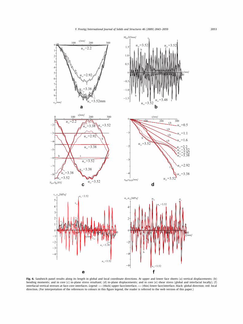
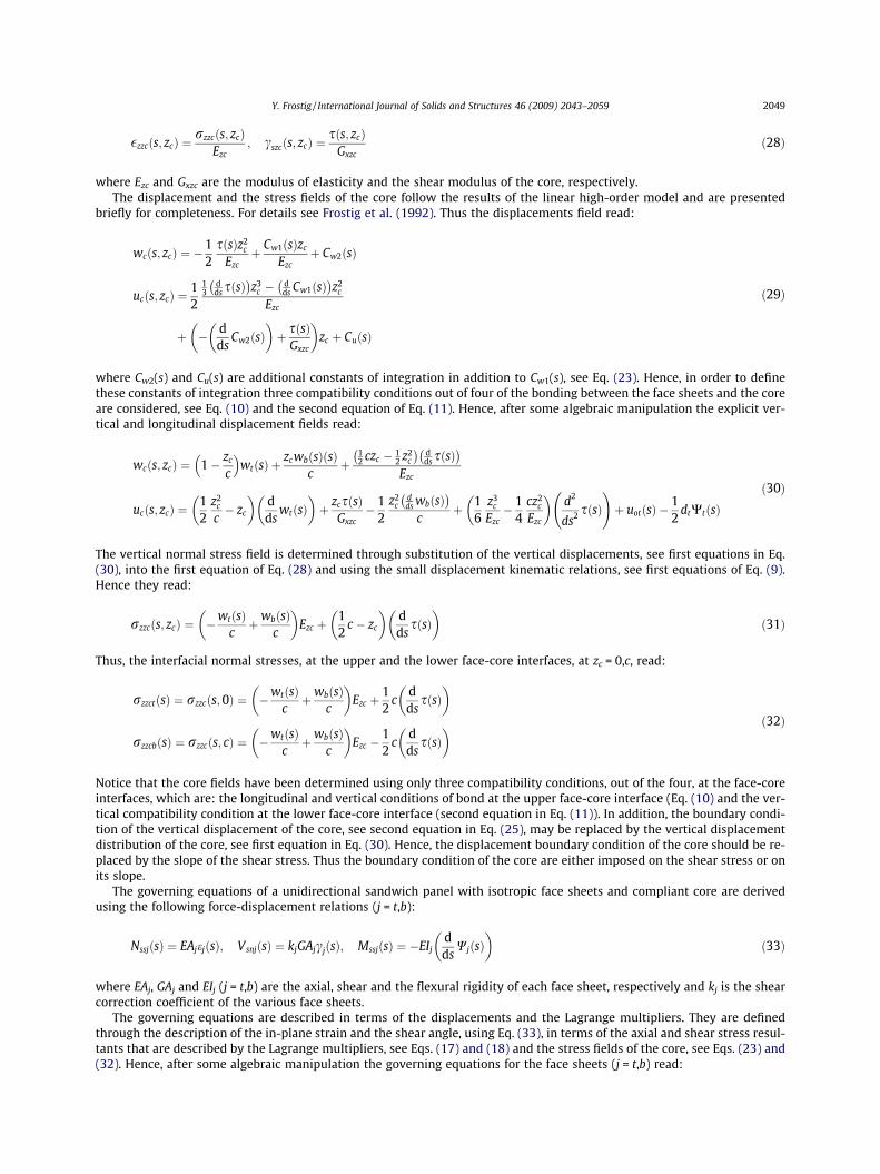
Fig. 6. Sandwich panel results along its length in global and local coordinate directions. At upper and lower face sheets (a) vertical displacements; (bbending moments; and in core (c) in-plane stress resultant; (d) in-plane displacements; and in core (e) shear stress (global and interfacial locally); (finterfacial vertical stresses at face-core interfaces. Legend: (thick) upper face/interface, (thin) lower face/interface, black: global direction; red: locadirection. (For interpretation of the references to colours in this figure legend, the reader is referred to the web version of this paper.)
Y. Frostig / International Journal of Solids and Structures 46 (2009) 2043–2059 2053
))l

2054 Y. Frostig / International Journal of Solids and Structures 46 (2009) 2043–2059
one in Fig. 5b. The ESL model is described by the centroidal line of the sandwich panel, denoted by c.g.esl, see Fig. 5a. In orderto achieve a non-trivial solution an imperfection of a small distributed load has been applied to the face sheets ofqzt = qzb = 0.01 N/mm and q = 0.00001 N/mm for the ESL model.
The results of the sandwich panel corresponds to a maximum end-shortening of uoe = 3.52 mm due to numerical difficul-ties while with the ESL model there is no limit and the maximum end-shortening considered reached a value of 495 mm.Numerically, the elastica problem of the sandwich panel is much more sensitive as compared with that of the ESL modelwhen the continuation method used for the two models are identical.
The deformed shape of the two panels appears in Fig. 5. The deformed shape of the sandwich panel appears in Fig. 5a andit describes the deformed shape of the panel at various compressive load levels that correspond to small (uoe = 2.2 mm) andlarge (uoe = 3.52 mm) end-shortening. At low load levels the panel exhibits overall buckling, see curve of uoe = 2.2 mm, wherethe two face sheets almost move the same. As the end-displacement increases and the corresponding compressive stressresultant decreases, see Fig. 7a ahead, around mid-span the upper face sheet wrinkles in addition to an overall buckling,see curves of uoe = 2.92–3.52 mm while the lower face sheet maintain almost a smooth curve with mild wrinkles. In thevicinity of the support the pattern changes and the lower face sheets wrinkles while the upper face sheet curve is smooth
vex
a
tt
t
b
b
b
2.0
b
ex
c
xz ex
d
zzex
Fig. 7. Equilibrium curves of a sandwich pane of load versus extreme values, in global coordinate system direction of (a) vertical displacements of facessheets; (b) bending moments in faces; (c) shear stress in core; (d) interfacial vertical stresses at face-core interfaces. Legend: positive value, . . .. . .
negative value, black: upper face sheet; red: lower face sheet. (For interpretation of the references to colours in this figure legend, the reader is referred tothe web version of this paper.)

Y. Frostig / International Journal of Solids and Structures 46 (2009) 2043–2059 2055
with mild wrinkles. The deformed shape of the ESL model appears in Fig. 5b and it exhibits overall buckling which is totallydifferent then that of the corresponding sandwich panel. The ESL model exhibits overall buckling with large deformationsand large end-shortening displacements, uoe = 14–495 mm, that correspond to compressive loads that decrease and in-creases, see Fig 9a ahead. Notice that when the end-shortening reaches values that are in the vicinity of the length of thepanel it moves upwards.
The results along the sandwich panel at various levels of end-shortening displacements appear in Fig. 6. The vertical dis-placements along the panel appear in Fig. 6a. It reveals that at low end-shortening displacements overall buckling is ob-served and as these prescribed displacements increase wrinkling of the upper face sheet around mid-span and lower facesheet in support vicinity, in addition to the overall buckling is detected. Notice that also the face sheet that does not buckleshas only small wrinkles. The bending moments at each of the face sheets, see Fig. 6b, reveal extremely high values at theupper face sheet and small ones at the lower one at large values of end-shortening at zones of positive overall bending mo-
,u =495 mmoe
u =495oe
u =495oe
u =495oe
u =495oe
u =495 mmoe
u =255oe
u =255oe
u =255oe
u =255oe
u =255oe
u =255oe
u =375oe
u =375oe
u =375oe
u =375oe
u =375oe
u =375oe
u =130oe
u =130oe
u =130oe
u =130oe
u =130oe
u =130oe
u =14oe
u =14oe
u =14oe
u =0.166oe
u =14oe
u =1.266oe
u =1.266oe
u =1.266oe
,
ba
c dFig. 8. ESL panel results along its length in global and local coordinate directions. (a) Vertical displacements; (b) slope of section; (c) bending moments(d) in-plane stress resultant; (e) in-plane displacements; (f) shear angle. Legend: (black), global direction; (red), local direction. (For interpretation othe references to colours in this figure legend, the reader is referred to the web version of this paper.)
;f

,
e
u =495oeu =495oe
u =495oe
u =255oe
u =255oe
u =255oe
u =375oeu =375oe
u =375oe
u =130oe
u =130oe
u =14oe
u =14oe
u =1.266oe
fFig. 8 (continued)
2056 Y. Frostig / International Journal of Solids and Structures 46 (2009) 2043–2059
ments around mid-span and an opposite trend at the negative bending moment, in the vicinity of the clamped support. Inaddition, notice that there are also bending moments at the simply-supported right edge although it is a moment free edge,due to the existence of an edge beam that the face sheets are fixed to. The overall bending moment at this edge is null whenthe in-plane compressive stress resultants in the face sheets are considered. The in-plane stress resultants, in local and globalcoordinate directions in the various face sheets, see Fig. 6c, are affected by the wrinkles as they deepens, see curves withuoe = 2.2–3.52 mm.. The longitudinal displacements of the face sheets appears in Fig. 6d and reveal non-smooth curves asa result of the wrinkles of the upper face sheets when the end-shortening displacement increases. The effect of the wrinklingof the face sheets on the shear stresses of the core (in the global vertical direction and in the and local direction at the upperand the lower face-core interface, ssnj (j = t,b)), see Fig. 6e, is significant and is associated with extremely large values for theinterfacial shear stresses in the local coordinate as a result of the large vertical interfacial normal stresses, see Fig. 6f. Themagnitude of the shear stress in the global coordinate is much smaller. The interfacial normal stresses at the upper andthe lower face sheets in the global and the local vertical directions appear in Fig. 6f. Notice, that also here the effects ofthe wrinkling of the upper face sheets are extremely large and yields an erratic behavior along the panel with large valuesand in addition the magnitude of the stresses in local the global coordinate are almost identical. In addition, notice that inFig. 6c, d and f the results in the global coordinates system and the local one, in red, almost coincides. In general, the non-regular wrinkling of the face sheets is associated with extremely large stresses that are quite erratic and are presented, espe-cially Fig. 6b, e and f, for the sake of visualization and completenace rather then for exact values.
The equilibrium curves of the compressive load in the horizontal direction that is induced at the right support as a resultof the prescribed end-shortening for various structural quantities appear in Fig. 7. Load versus the extreme vertical displace-ment along the panel appears in Fig. 7a. The curves reveal that up to the buckling load, at about 12.7 kN, the extreme verticaldisplacement is almost null and there is an abrupt change in the displacement as this load is reached. In the post-bucklingrange the displacement increases while the load decreases which reflects a shell type of post-buckling behavior. Notice thatthe curves of the two face sheets are almost identical. The same trends are observed for the extreme bending moment in theface sheets, see Fig. 7b, the shear stress in the core in the global vertical direction and in the vertical interfacial stresses, in thevertical direction, at the upper and the lower face core interfaces, see Fig. 7d.
The results of the ESL model along the panel appear in Fig. 8. The vertical displacements in the global and local coordinatesystem directions appear in Fig. 8a. They reveal that there is a global buckling response with a continuous decrease as theend-shortening displacement increases and they change from a downward vertical displacement as the end-shorteningreaches values that are in the vicinity of the length of the panel. The same trends are observed for the slope of the section,see Fig. 8b. The bending moments exhibits similar trends, see Fig. 8c, and they reach large values as the prescribed end-short-ening increases. The in-plane stress resultants in the local and global directions appear in Fig. 8d. The stress resultants in thehorizontal global direction are uniform through the entire length of the panel. The compressive stress resultants in the localdirection even change to tensile ones near the right edge of the panel. The in-plane displacements, in the global and localdirections, appear in Fig. 8e. The global ones are negative and correspond to the end-shortening at right support whilethe local ones change form negative to positive as the prescribed displacements increases. The shear angle appears in

Y. Frostig / International Journal of Solids and Structures 46 (2009) 2043–2059 2057
Fig. 8f and is very similar to the slope of the section, see Fig. 8b. Notice that the shear angle are quite large and at the highend-shortening values they exceeds the range of moderate strains.
The equilibrium curves of the ESL model for various extreme structural quantities appear in Fig. 9. Fig. 9a describes thehorizontal compressive load exerted at the right support of the panel through the prescribed end-shortening versus the ex-treme vertical (in global direction) deflection within the panel length. The curve reveals a bifurcation point, at about 18.5 kN.Notice that up to the bifurcation load there is an increase in the load with very small displacement. Beyond the bifurcationpoint any increase in the end-shortening is associated with an increase in the vertical displacement without any increase inthe load (horizontal reaction at end-shortening location). At a certain point when the end-shortening is about the length ofthe panel there is a continuous decline in the load and the displacements up to a very small load and the load increases whilethe vertical displacement decreases. A similar pattern of the load as the end-shortening increases appears in Wang (1997) fora non-extensional clamped-simply-supported beam. In the case of the load versus the extreme bending moment, see Fig. 9b,the bifurcation point is clearly observed and again the bending moment even drops as the end-shortening increases. The loadversus the in-plane stress resultants (in global, denoted by Nhex , and local, Nssex , directions) appear in Fig. 9c. The load versusthe compressive stress resultants, in the global direction, is linear where the external loads and the in-plane stress resultants
vexa
ex
b
,ex
ex
ex
ex
ex
cex
dFig. 9. Equilibrium curves of ESL panel of external load versus of extreme values in global coordinates systems of (a) vertical displacement; (b) bendingmoment; (c) in-plane stress resultant (local as well as global); (d) in-plane displacements. Legend: (black), global direction; (red), local direction;positive values; ----, negative values. (For interpretation of the references to colours in this figure legend, the reader is referred to the web version of this paper.)
ESL
ESL
SandwichPanel
w [mm]
N [kN]e
vex
Fig. 10. Load versus extreme vertical displacement, in global direction, of sandwich panel and ESL model.
2058 Y. Frostig / International Journal of Solids and Structures 46 (2009) 2043–2059
are identical. The in-plane stress resultants in the local direction change from compression to tension as the end-shorteningexceeds the bifurcation point. The in-plane displacement in the global direction appears in Fig. 9d and exhibits a continuosincreases as the load decreases and increases beyond the bifurcation point.
A comparison between the sandwich panel and its ESL model reveal a totally different response even for small end-short-ening in all structural aspects. A detailed comparison of the equilibrium curves of load versus vertical displacement in thetwo model appears in Fig. 10. The curves reveal that the bifurcation load of the sandwich panel is smaller, about 12.9 kN,then that of the ESL one, of about 18.5 kN, and the post-buckling curve are quit different. The post-buckling response ofthe sandwich panel is associated with a drop in the load as the displacement increases while the ESL described a beambehavior where the load remains constant while the vertical displacement increases and at a certain point when the end-shortening is in the vicinity of the length of the panel, the load and the vertical displacements decreases. Hence, the elasticaresponse of the ESL panel is totally different and should not be used to simulate the elastica behavior of a real sandwichpanel.
4. Summary and conclusions
The elastica behavior of a sandwich panel with a soft/compliant core is presented. The analysis considers the shear defor-mations in the face sheets using the first-order shear deformation theory (FOSDT) in addition to the flexural ones and takesinto account the extension of the centroid lines of the face sheets. The kinematic relations adopted are based on large dis-placements and large rotations with moderate strains. The strains adopted coincide with Reissner strains only when thestrains and shear angles are small to moderate. The mathematical formulation is based on a variational approach and usesLagrange coefficient to impose the special strain relations (Reissner strains). The formulation is general and can be applied toany type of structural layout. Here, it has been applied to isotropic face sheets and core for simplicity and brevity.
The elastica behavior of a single layer panel (ESL model) with shear deformations is presented for comparison with thereal sandwich panel. The ESL formulation uses the basic equations of a face sheet of the sandwich panel but with the con-ditions that the shear and interfacial vertical normal stresses are null along with equivalent mechanical properties.
The numerical study presents the results of a sandwich panel with edge beam constraints and its equivalent one wherethe shear deformation of the core is considered while that of the face sheets is neglected. The numerical results are describedin terms of deformed shapes, structural quantities along the panel, and equilibrium curves of load versus extreme structuralquantities.
The numerical investigation reveals that the sandwich panel reaches a bifurcation point in a global buckling mode andwrinkles in addition to the global buckling within the post-buckling range. This wrinkling phenomenon is associated witha drop in the load as the imposed end-shortening increases. Thus, a shell buckling behavior with a snap through may occurwhen a load control test is conducted. The wrinkling waves are also associated with extremely large stresses and deforma-
Y. Frostig / International Journal of Solids and Structures 46 (2009) 2043–2059 2059
tions. In addition, a numerical instability of the governing equations has been observed as a result of the loss of the physicalstability deep in the post-buckling range that is associated with a reduction of the load as the displacement increases.
The ESL response follows the well known response of elastica of slender beams with an overall buckling. The numericalsolution is stable due to the fact that the response is physically stable and as the displacement increases the load remainalmost constant and drops only when the end-shortening reaches values that are about the length of the panel. The bifur-cation load in this case is higher then that of the sandwich panel.
The comparison between the elastica response of the sandwich panel and that of the ESL model reveal a totally differentbehavior. Hence, the use of an ESL model to simulate the real behavior of a sandwich panel may be quite inaccurate. Thus, inorder to detect the real failure patterns of sandwich panels which exceed large deformations the proposed elastica formu-lation must be used.
References
Allen, H.G., 1969. Analysis and Design of Structural Sandwich Panels. Pergamon Press, London.Ascher, U.M., Petzold, L., 1998. Computer Methods for Ordinary Differential Equations and Differential–Algebraic Equations. SIAM, Philadelphia.Bazant, Z.P., Beghini, A., 2006. Stability and finite strain of homogenized structure soft in shear: sandwich or fiber composites and layered bodies.
International Journal of Solids and Structures 43, 1571–1593.Char, B.W., Gedddes, K.O., Gonnet, G.H., Leong, B.L., Monagan, M.B., Watt, S.M., 1991. Maple V library Reference Manual. Springer-Verlag, New York.Chucheepsakul, S., Huang, T., 1997. Finite-element solution of variable-arc-length beams under a point load. Journal of Structural Engineering ASCE 123 (7),
968–970.Coffin, D.W., Bloom, F., 1999. Elastica solution of Hygrothermal buckling of a beam. International Journal of Non-Linear Mechanics 34, 935–947.Dym, C.L., Shames, I.H., 1973. Solid Mechanics, A Variational Approach. McGraw-Hill, Kogakusha.Flajs, R., Saje, M., Zakrajsek, E., 2003. On the existence and uniqueness of the generalized solution of Reissner’s elastica. Mathematical and Mechanics of
Solids 8, 3–19.Frostig, Y., Baruch, M., Vilnay, O., Sheinman, I., 1992. A high order theory for the bending of sandwich beams with a flexible core. Journal of ASCE, EM
Division 118 (5), 1026–1043.Frostig, Y., 1992. Behavior of delaminated sandwich beams with transversely flexible core—high order theory. Composite Structures Journal 20 (Jan.), 1–16.Frostig, Y., Baruch, M., 1993. Buckling of simply-supported sandwich beams with transversely flexible core—a high order theory. Journal of ASCE, EM
Division 119 (3), 476–495.Frostig, Y., 1998. Buckling of sandwich panels with a transversely flexible core—high-order theory. International Journal of Solids and Structures 35 (3–4),
183–204.Frostig, Y., Thomsen, O.T., 2005. Localized effects in the non-linear behavior of sandwich panels with a transversely flexible core. Journal of Sandwich
Structures and Materials 7 (1), 53–75.Hohe, J., Librescu, L., 2003. A nonlinear theory for doubly curved anisotropic sandwich shells with transversely compressible core. International Journal of
Solids and Structures 40 (5), 1059–1088.Huang, H., Kardomateas, G.A., 2002. Buckling and initial post-buckling behavior of sandwich beams including transverse shear. AIAA Journal 40 (11), 2331–
2335.Keller, H.B., 1992. Numerical Methods for Two-point Boundary Value Problems. Dover Publications, New York.Lee, K., 2001. Post-buckling of a uniform cantilever column under a combined load. International Journal of Non-Linear Mechanics 36, 813–816.Lee, K., 2002. Large deflections of cantilever beams of non-linear elastic material under combined loading. International Journal of Non-Linear Mechanics 37,
439–443.Ligamov, M.A., Ratrout, R.A., 1999. Large deflection of superconducting cable. International Journal of Non-Linear Mechanics 34, 869–880.Madhusudan, B.P., Rajeev, V.R., Rao, B.N., 2003. Post-buckling of cantilever columns having variable cross-section under a combined load. International
Journal of Non-Linear Mechanics 38, 1513–1522.Mindlin, R.D., 1951. Influence of transverse shear deformation on the bending of classical plates. Transaction of ASME, Journal of Applied Mechanics 18, 31–
38.Pak, R.Y.S., Stauffer, E.J., 1993. Non-linear finite deformation analysis of beam and columns. Journal of Engineering Mechanics, ASCE 120 (10), 2136–2153.Petras, A., Sutcliffe, M.P.F., 1999. Indentation resistance of sandwich beams. Composite Structures 46 (4), 413–424. Dec.Petras, A., Sutcliffe, M.P.F., 2000. Indentation failure analysis of sandwich beams. Composite Structures 50 (3), 311–318. Nov.Plantema, F.J., 1966. Sandwich Construction. John Wiley and Sons, New York.Reddy, J.N., 1984. Energy and Variational Methods in Applied Mechanics. John Wiley and Sons, Inc., New York.Reissner, E., 1972. On one-dimensional finite strain beam theory: the plane problem. Journal of Applied Mathematics and Physics (ZAMP) 23, 795–804.Sokolinsky, V., Frostig, Y., 2000. Branching behavior in the non-linear response of sandwich panels with a transversely flexible core. International Journal of
Solids and Structures 37 (November), 5745–5772.Sokolinsky, V.S., Shen, H., Vaikhanski, L., Nutt, S.R., 2003. Experimental and analytical study of nonlinear bending response of sandwich beams. Composite
Structures 60 (2), 219–229. May.Stoer, J., Bulirsch, R., 1980. Introduction to Numerical Analysis. Springer, New York.Swanson, S.R., 1999. An examination of a high-order theory for sandwich beams. Composite Structures 44 (2–3), 169–177.Vinogradov, A.M., Derrick, W.R., 2000. Structure–material relations in the buckling problem of asymmetric composite columns. International Journal of
Non-Linear Mechanics 35, 167–175.Vinson, J.R., 1999. The behavior of Sandwich Structures of Isotropic and Composite Materials. Technomic Publishing Co. Inc., Lancaster.Wang, C.Y., 1997. Post-buckling of a clamped-simply-supported elastica. International Journal of Non-Linear Mechanics 32 (6), 1115–1122.Zenkert, D., 1995. An Introduction to Sandwich Construction. Chameleon Press Ltd, London.

![Proximal ADMM for Euler’s Elastica Based Image ... · Proximal ADMM for Euler’s Elastica Based Image Decomposition Model 371 such as texture and noise; See, e.g. [3,15,25,26,34,39,44,45].](https://static.fdocuments.in/doc/165x107/5e3b89084ab78e41b8495b8b/proximal-admm-for-euleras-elastica-based-image-proximal-admm-for-euleras.jpg)