Elastic-Buffer Flow Control for On-Chip Networks · 2012-12-10 · Elastic-Buffer Flow Control for...
12
Elastic-Buffer Flow Control for On-Chip Networks George Michelogiannakis, James Balfour and William J. Dally Computer Systems Laboratory, Stanford University, Stanford, CA 94305 {mihelog,jbalfour,dally}@cva.stanford.edu Abstract This paper presents elastic buffers (EBs), an efficient flow-control scheme that uses the storage already present in pipelined channels in place of explicit input virtual- channel buffers (VCBs). With this approach, the channels themselves act as distributed FIFO buffers. Without VCBs, and hence virtual channels (VCs), deadlock prevention is achieved by duplicating physical channels. We develop a channel occupancy detector to apply universal globally adaptive load-balancing (UGAL) routing to load balance traffic in networks using EBs. Using EBs results in up to 8% (12% for low-swing channels) improvement in peak throughput per unit power compared to a VC flow-control network. These gains allow for a wider network datapath to be used to offset the removal of VCBs and increase through- put for a fixed power budget. EB networks have identical zero-load latency to VC networks operating under the same frequency. The microarchitecture of an EB router is con- siderably simpler than a VC router because allocators and credits are not required. For 5×5 mesh routers, this results in an 18% improvement in the cycle time. 1 Introduction Semiconductor technology scaling allows more process- ing and storage elements to be integrated on the same die. Networks-on-chip (NoCs) provide a scalable communica- tion infrastructure [5,7]. With wires available in abundance on chip, channel bandwidth is plentiful, rendering buffers and flip-flops (FFs) expensive in comparison [5]. Thus, reducing buffering requirements and implementing buffers more efficiently increases network efficiency. This paper presents elastic buffers (EBs), an efficient flow-control scheme that uses the storage already present in pipelined channels instead of input virtual-channel buffers (VCBs). Removing VCBs reduces the area and power con- sumed by routers, but prevents the use of virtual-channel flow-control for performance and deadlock avoidance. Du- plicate physical channels can be used in the same way as virtual channels (VCs) to prevent deadlocks and to de- fine traffic classes. Dividing a network into sub-networks provides duplicate physical channels and increases perfor- mance and power efficiency [1] in virtual-channel networks (VCNs), which we find to hold for elastic-buffered net- works (EBNs). We use universal globally-adaptive load-balanced (UGAL) routing [18] in a flattened butterfly (FBFly) [11] network to balance network load. We develop a channel congestion sensing mechanism for EBNs that is used in place of the credit count that is typically used to sense congestion in VCNs. For a FBFly with UGAL routing, performance and power efficiency are almost equal for EBNs and VCNs with low-swing channels, with a 3% loss for EBNs with full- swing channels. EBN gains in 2D mesh networks reach 8%, increasing to 12% with low-swing channels. EBN gains de- pend on the fraction of cost represented by VCBs. Since the EBN datapath must be widened to compensate for the removal of VCBs, EBNs tend to occupy more area. For a fixed area budget, datapath widths are similar, and VCNs are more area efficient. Zero-load latency is equal for VCNs and EBNs operating at the same clock frequency. EB routers are simpler than VC routers because they use arbiters rather than allocators, and do not use credit- based flow-control. Consequently, the critical paths in an EB router are shorter than a comparable VC router. An EB router can operate at a faster clock frequency. For 5×5 mesh routers, EB routers have an 18% reduced cycle time. The rest of this paper is organized as follows: Section 2 discusses the basic building blocks of EBNs as well as dead- lock avoidance, topology choices and adaptive routing. Sec- tion 3 presents performance, area and power evaluations. Section 4 discusses EBNs and trade-offs. Section 5 outlines router implementation results. Finally, sections 6 and 7 con- clude and discuss related work. 2 Elastic Buffer Networks In this section we present EB channels and routers, the fundamental EBN building blocks. We then discuss channel To appear in the 15th International Symposium on High-Performance Computer Architecture (HPCA-15).
Transcript of Elastic-Buffer Flow Control for On-Chip Networks · 2012-12-10 · Elastic-Buffer Flow Control for...

Elastic-Buffer Flow Control for On-Chip Networks
George Michelogiannakis, James Balfour and William J. DallyComputer Systems Laboratory, Stanford University, Stanford, CA 94305
{mihelog,jbalfour,dally}@cva.stanford.edu
Abstract
This paper presents elastic buffers (EBs), an efficientflow-control scheme that uses the storage already presentin pipelined channels in place of explicit input virtual-channel buffers (VCBs). With this approach, the channelsthemselves act as distributed FIFO buffers. Without VCBs,and hence virtual channels (VCs), deadlock prevention isachieved by duplicating physical channels. We developa channel occupancy detector to apply universal globallyadaptive load-balancing (UGAL) routing to load balancetraffic in networks using EBs. Using EBs results in upto 8% (12% for low-swing channels) improvement in peakthroughput per unit power compared to a VC flow-controlnetwork. These gains allow for a wider network datapath tobe used to offset the removal of VCBs and increase through-put for a fixed power budget. EB networks have identicalzero-load latency to VC networks operating under the samefrequency. The microarchitecture of an EB router is con-siderably simpler than a VC router because allocators andcredits are not required. For 5×5 mesh routers, this resultsin an 18% improvement in the cycle time.
1 Introduction
Semiconductor technology scaling allows more process-ing and storage elements to be integrated on the same die.Networks-on-chip (NoCs) provide a scalable communica-tion infrastructure [5,7]. With wires available in abundanceon chip, channel bandwidth is plentiful, rendering buffersand flip-flops (FFs) expensive in comparison [5]. Thus,reducing buffering requirements and implementing buffersmore efficiently increases network efficiency.This paper presents elastic buffers (EBs), an efficient
flow-control scheme that uses the storage already present inpipelined channels instead of input virtual-channel buffers(VCBs). Removing VCBs reduces the area and power con-sumed by routers, but prevents the use of virtual-channelflow-control for performance and deadlock avoidance. Du-plicate physical channels can be used in the same way
as virtual channels (VCs) to prevent deadlocks and to de-fine traffic classes. Dividing a network into sub-networksprovides duplicate physical channels and increases perfor-mance and power efficiency [1] in virtual-channel networks(VCNs), which we find to hold for elastic-buffered net-works (EBNs).We use universal globally-adaptive load-balanced
(UGAL) routing [18] in a flattened butterfly (FBFly) [11]network to balance network load. We develop a channelcongestion sensing mechanism for EBNs that is used inplace of the credit count that is typically used to sensecongestion in VCNs.For a FBFly with UGAL routing, performance and
power efficiency are almost equal for EBNs and VCNs withlow-swing channels, with a 3% loss for EBNs with full-swing channels. EBN gains in 2D mesh networks reach 8%,increasing to 12% with low-swing channels. EBN gains de-pend on the fraction of cost represented by VCBs. Sincethe EBN datapath must be widened to compensate for theremoval of VCBs, EBNs tend to occupy more area. Fora fixed area budget, datapath widths are similar, and VCNsare more area efficient. Zero-load latency is equal for VCNsand EBNs operating at the same clock frequency.EB routers are simpler than VC routers because they
use arbiters rather than allocators, and do not use credit-based flow-control. Consequently, the critical paths in anEB router are shorter than a comparable VC router. An EBrouter can operate at a faster clock frequency. For 5×5 meshrouters, EB routers have an 18% reduced cycle time.The rest of this paper is organized as follows: Section 2
discusses the basic building blocks of EBNs as well as dead-lock avoidance, topology choices and adaptive routing. Sec-tion 3 presents performance, area and power evaluations.Section 4 discusses EBNs and trade-offs. Section 5 outlinesrouter implementation results. Finally, sections 6 and 7 con-clude and discuss related work.
2 Elastic Buffer Networks
In this section we present EB channels and routers, thefundamental EBN building blocks. We then discuss channel
To appear in the 15th International Symposium on High-Performance Computer Architecture (HPCA-15).

(a) A DFF implemented with a master and aslave D latch.
(c) Expanded view of the EB control logic as a synchronousFSM for two-slot EBs.
(b) An EB is a FF whose latches are con-trolled by the EB control logic and used forbuffering.
(d) Logic diagram of the EB control FSM with 2 FFs and 10gates.
Figure 1. EB Channels.duplication, deadlock avoidance, and adaptive routing.
2.1 Elastic Buffer Channels
Figure 1(a) shows a D flip-flop (DFF) [19] that is imple-mented using master and slave latches. By adding controllogic to drive the latch enable pins independently, each latchcan be used as an independent storage location. Thus, theFF becomes an EB, a FIFO with two storage locations. Thisis illustrated in Figure 1(b).EB channels use many such EBs to form a distributed
FIFO. FIFO storage can be increased by adding latches toEBs or by using repeater cells for storage [15]. EBs use aready-valid handshake to advance a flit (flow-control digit).An upstream ready (R) signal indicates that the downstreamEB has at least one empty storage location and can storean additional flit. A downstream valid (V) signal indicatesthat the flit currently being driven is valid. A flit advanceswhen both the ready and valid signals between two EBs areasserted at the rising clock edge. This timing conventionrequires at least two storage slots per clock cycle delay toavoid creating unnecessary pipeline bubbles.The finite state machine (FSM) implementing the EB
control logic is illustrated in Figure 1(c), and the corre-sponding logic is shown in Figure 1(d). The FSM outputs
that control the latch enables are qualified by the clock inthe same manner as FFs. A flit is latched in the master latchat the end of the cycle and advances to the slave at the be-ginning of the next cycle. The initial state, state 0, encodesthat there are no valid flits stored. E2 can be 0 in state 0to save power or 1 to simplify FSM logic. Once a flit ar-rives (V in=1), the FSM enters the state 1 new, because thearriving flit is stored at the master latch at the beginning ofthe cycle and thus needs to be moved to the slave latch byasserting E2. If the flit does not depart and no new flit ar-rives, the FSM enters the state 1 old, because the flit alreadyresides in the slave latch and it must not be overwritten. Instate 2, there are two stored flits which makes the FSM de-assert both latch enables to prevent overwriting. The masterlatch enable can be further qualified by the incoming validto avoid clocking the master latch when there are no incom-ing flits. The total FSM cost is 2 FFs and 10 logic gates.Two more AND gates are needed to qualify the FSM latchenable outputs by the clock. Since flow-control is applied ata flit granularity, control logic is amortized over the widthof the channel. The channel datapath is unaffected.All components use the same clock. To avoid penalizing
its frequency, we hide the FSM setup time and clock-to-qlatency. Since the EB master latch is enabled only when theclock is low, the first half of the clock cycle is long enough
To appear in the 15th International Symposium on High-Performance Computer Architecture (HPCA-15).
for the single AND gate to drive E1. However, E2 needs tobe stable during the first half of the clock cycle. Therefore,we split the FFs holding state bits a and b into their masterand slave latches. The outputs of the master latches are usedto generate E2, allowing E2 to stabilize before the end of theprevious clock cycle.To cover the overhead of the ready and valid ports, the
ready and valid wires are optimized for delay by promot-ing them to higher metal layers with lower RC delays, byincreasing wire width and spacing, or by engineering thewires for delay using more aggressive repeaters. The ready-valid overhead consists of an 1 fanout-of-four (FO4) latchdata-to-q delay, 3 FO4 logic delay (for the three levels ofgates in the FSM next-state and output functions), and 3FO4 to fanout the latch enables to the channel EBs, for a to-tal of 7 FO4. In our implementation technology, explainedin section 3.1, if we assume 1mm EB spacing, the 7 FO4overhead can be hidden by targeting a ready and valid wiredelay of 360ps/mm instead of 500ps/mm. The minimumpropagation delay for wires engineered solely for delay is150ps/mm in our technology.
2.2 Router Architecture
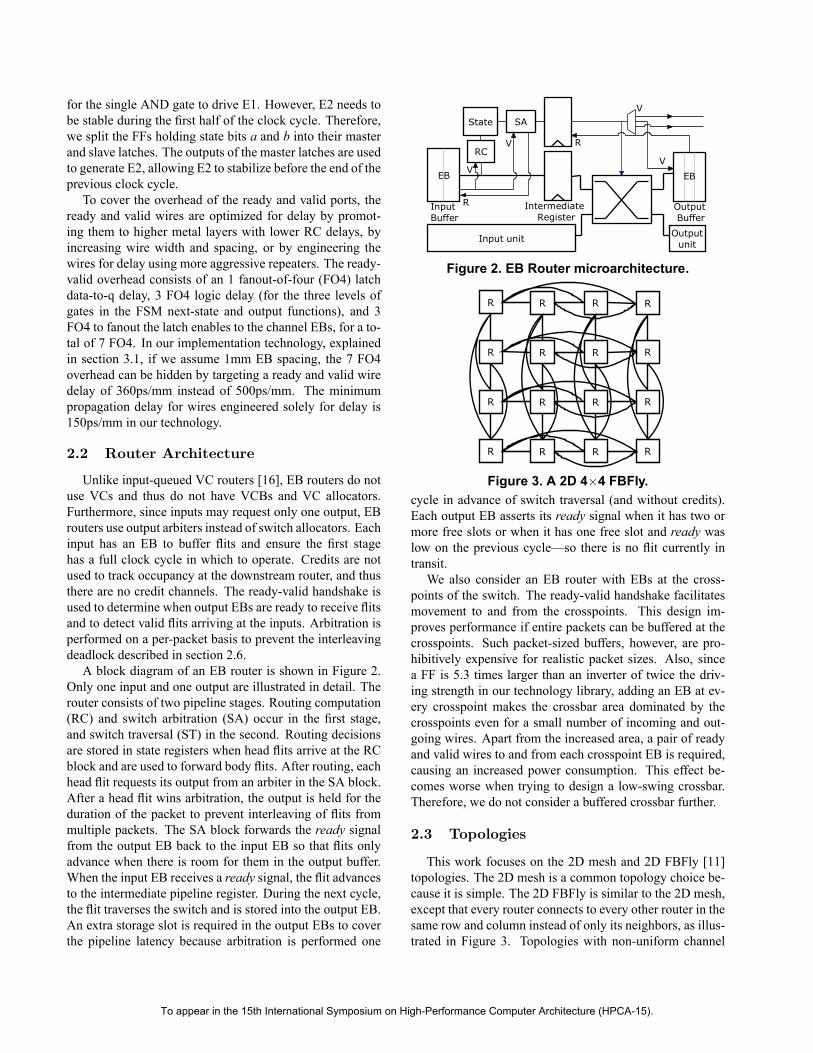
Unlike input-queued VC routers [16], EB routers do notuse VCs and thus do not have VCBs and VC allocators.Furthermore, since inputs may request only one output, EBrouters use output arbiters instead of switch allocators. Eachinput has an EB to buffer flits and ensure the first stagehas a full clock cycle in which to operate. Credits are notused to track occupancy at the downstream router, and thusthere are no credit channels. The ready-valid handshake isused to determine when output EBs are ready to receive flitsand to detect valid flits arriving at the inputs. Arbitration isperformed on a per-packet basis to prevent the interleavingdeadlock described in section 2.6.A block diagram of an EB router is shown in Figure 2.
Only one input and one output are illustrated in detail. Therouter consists of two pipeline stages. Routing computation(RC) and switch arbitration (SA) occur in the first stage,and switch traversal (ST) in the second. Routing decisionsare stored in state registers when head flits arrive at the RCblock and are used to forward body flits. After routing, eachhead flit requests its output from an arbiter in the SA block.After a head flit wins arbitration, the output is held for theduration of the packet to prevent interleaving of flits frommultiple packets. The SA block forwards the ready signalfrom the output EB back to the input EB so that flits onlyadvance when there is room for them in the output buffer.When the input EB receives a ready signal, the flit advancesto the intermediate pipeline register. During the next cycle,the flit traverses the switch and is stored into the output EB.An extra storage slot is required in the output EBs to coverthe pipeline latency because arbitration is performed one
Figure 2. EB Router microarchitecture.
Figure 3. A 2D 4×4 FBFly.cycle in advance of switch traversal (and without credits).Each output EB asserts its ready signal when it has two ormore free slots or when it has one free slot and ready waslow on the previous cycle—so there is no flit currently intransit.We also consider an EB router with EBs at the cross-
points of the switch. The ready-valid handshake facilitatesmovement to and from the crosspoints. This design im-proves performance if entire packets can be buffered at thecrosspoints. Such packet-sized buffers, however, are pro-hibitively expensive for realistic packet sizes. Also, sincea FF is 5.3 times larger than an inverter of twice the driv-ing strength in our technology library, adding an EB at ev-ery crosspoint makes the crossbar area dominated by thecrosspoints even for a small number of incoming and out-going wires. Apart from the increased area, a pair of readyand valid wires to and from each crosspoint EB is required,causing an increased power consumption. This effect be-comes worse when trying to design a low-swing crossbar.Therefore, we do not consider a buffered crossbar further.
2.3 Topologies
This work focuses on the 2D mesh and 2D FBFly [11]topologies. The 2D mesh is a common topology choice be-cause it is simple. The 2D FBFly is similar to the 2D mesh,except that every router connects to every other router in thesame row and column instead of only its neighbors, as illus-trated in Figure 3. Topologies with non-uniform channel
To appear in the 15th International Symposium on High-Performance Computer Architecture (HPCA-15).

(a) The two routers, one for each sub-network. Illustratedfor a 4×4 UGAL FBFly.
(b) A 3×3 UGAL FBFly. Non-minimal router (NM) connect tominimal routers (M – shaded) via X’ channels.
Figure 4. The UGAL FBFly. Two traffic classes are defined by two sub-networks.lengths, such as the FBFly, require VC routers with differ-ent amounts of buffering at each input to account for thedifferent credit round-trip delays, which increases the de-sign complexity, or with large enough buffers to accommo-date the longest channels. EBNs avoid this because they donot use credits.Using UGAL routing (section 2.5) in an EBN requires
separate traffic classes to handle minimal and non-minimaltraffic to prevent cyclic dependencies (section 2.6). As dis-cussed in section 2.7, the most efficient way to implementthese traffic classes is to provide separate sub-networks forminimal and non-minimal traffic. A single FBFly router isreplaced by a router for each of the two sub-networks, asillustrated in Figure 4(a). The X’ and Y’ channels handlenon-minimal packets while the X and Y channels handleminimal traffic. The Y’ channels connect the non-minimalrouters to other non-minimal routers in the same column.The X’ channels connect the non-minimal routers to theminimal routers in the same row. After a packet takes anX’ hop it is done with non-minimal routing and proceedsto its destination on the minimal sub-network. One of theX’ channels connects each non-minimal router to the mini-mal router with the same coordinates. This handles packetsthat do not require a non-minimal hop in X. Traffic sourcesinject traffic to the non-minimal sub-network. Destinationseject traffic from the minimal sub-network. A 3×3 UGALFBFly is shown in Figure 4(b).
2.4 Sensing Channel Congestion
The UGAL [18] routing algorithm we use for the FBFlytopology requires a means of estimating channel conges-tion. We evaluate five different congestion metrics forEBNs that can be used instead of the credit counts usedby VCNs: blocked cycles, blocked ratio, output occupancy,channel occupancy, and channel delay.Blocked Cycles is a running average of the number of
cycles an output is blocked. Once an output is blocked,a counter keeps track of the number of clock cycles un-
Figure 5. Measuring output occupancy.til it unblocks. At that point it updates the running aver-age. The new value for running averages is calculated asnewvalue = 0.3 × oldvalue + 0.7 × newsample.Blocked Ratio is the ratio of the number of cycles an out-
put has been blocked, divided by its unblocked cycles. Wecalculate this for the 20 most recent clock cycles.Output Occupancy is the number of flits currently com-
mitted to an observation region of the channel. When thehead flit of a packet is routed, the occupancy counter for itsoutput is incremented by the packet length in flits. Outputcounters are decremented by one for each flit leaving theobservation region, the output channel segment for whichwe keep track of flits in transit.We detect flits leaving the observation region using an
AND gate whose inputs are the ready and valid signals be-tween the last EB of the region of observation and the nextEB. A circuit to measure output occupancy for a single out-put is shown in Figure 5. The time required to propagatethe AND gate output back to the router, determined by thelength of the observation region, affects the speed of con-gestion sensing. As discussed in section 2.1, that wire canbe optimized for delay to accommodate larger regions. Inour study, the observation region is the same length as theshortest network channel. Propagation delay is half of thatchannel’s delay, rounded up.Channel Occupancy is similar to output occupancy, ex-
cept that an output’s counter is incremented when a flit ar-
To appear in the 15th International Symposium on High-Performance Computer Architecture (HPCA-15).
0 10 20 30 40 50 60
Progressive
Non-progressive
Average maximum throughput (flits/cycle * 100)
Channel Delay
Channel Occupancy
Output Occupancy
Blocked Ratio
Blocked Cycles
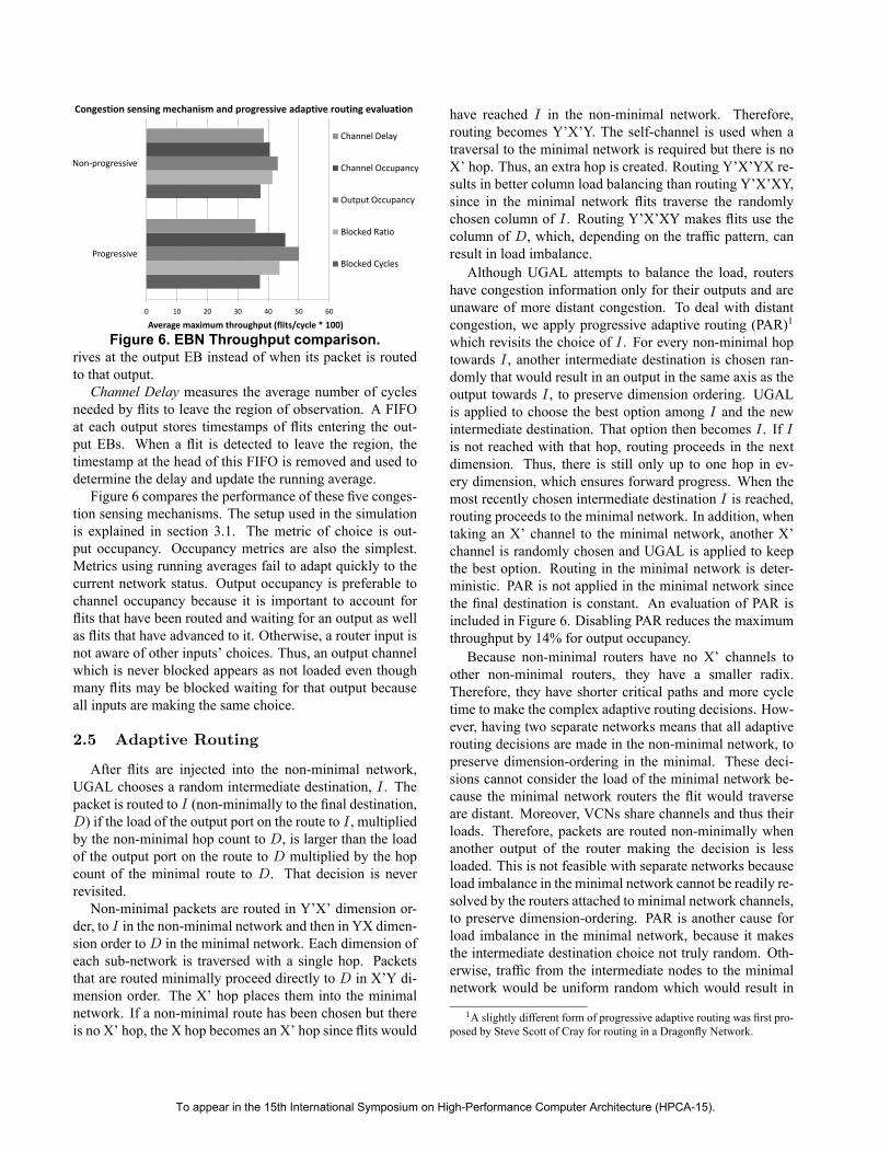
Congestion sensing mechanism and progressive adaptive routing evaluation
Figure 6. EBN Throughput comparison.rives at the output EB instead of when its packet is routedto that output.Channel Delay measures the average number of cycles
needed by flits to leave the region of observation. A FIFOat each output stores timestamps of flits entering the out-put EBs. When a flit is detected to leave the region, thetimestamp at the head of this FIFO is removed and used todetermine the delay and update the running average.Figure 6 compares the performance of these five conges-
tion sensing mechanisms. The setup used in the simulationis explained in section 3.1. The metric of choice is out-put occupancy. Occupancy metrics are also the simplest.Metrics using running averages fail to adapt quickly to thecurrent network status. Output occupancy is preferable tochannel occupancy because it is important to account forflits that have been routed and waiting for an output as wellas flits that have advanced to it. Otherwise, a router input isnot aware of other inputs’ choices. Thus, an output channelwhich is never blocked appears as not loaded even thoughmany flits may be blocked waiting for that output becauseall inputs are making the same choice.
2.5 Adaptive Routing
After flits are injected into the non-minimal network,UGAL chooses a random intermediate destination, I . Thepacket is routed to I (non-minimally to the final destination,D) if the load of the output port on the route to I , multipliedby the non-minimal hop count to D, is larger than the loadof the output port on the route to D multiplied by the hopcount of the minimal route to D. That decision is neverrevisited.Non-minimal packets are routed in Y’X’ dimension or-
der, to I in the non-minimal network and then in YX dimen-sion order toD in the minimal network. Each dimension ofeach sub-network is traversed with a single hop. Packetsthat are routed minimally proceed directly to D in X’Y di-mension order. The X’ hop places them into the minimalnetwork. If a non-minimal route has been chosen but thereis no X’ hop, the X hop becomes an X’ hop since flits would
have reached I in the non-minimal network. Therefore,routing becomes Y’X’Y. The self-channel is used when atraversal to the minimal network is required but there is noX’ hop. Thus, an extra hop is created. Routing Y’X’YX re-sults in better column load balancing than routing Y’X’XY,since in the minimal network flits traverse the randomlychosen column of I . Routing Y’X’XY makes flits use thecolumn of D, which, depending on the traffic pattern, canresult in load imbalance.Although UGAL attempts to balance the load, routers
have congestion information only for their outputs and areunaware of more distant congestion. To deal with distantcongestion, we apply progressive adaptive routing (PAR)1which revisits the choice of I . For every non-minimal hoptowards I , another intermediate destination is chosen ran-domly that would result in an output in the same axis as theoutput towards I , to preserve dimension ordering. UGALis applied to choose the best option among I and the newintermediate destination. That option then becomes I . If Iis not reached with that hop, routing proceeds in the nextdimension. Thus, there is still only up to one hop in ev-ery dimension, which ensures forward progress. When themost recently chosen intermediate destination I is reached,routing proceeds to the minimal network. In addition, whentaking an X’ channel to the minimal network, another X’channel is randomly chosen and UGAL is applied to keepthe best option. Routing in the minimal network is deter-ministic. PAR is not applied in the minimal network sincethe final destination is constant. An evaluation of PAR isincluded in Figure 6. Disabling PAR reduces the maximumthroughput by 14% for output occupancy.Because non-minimal routers have no X’ channels to
other non-minimal routers, they have a smaller radix.Therefore, they have shorter critical paths and more cycletime to make the complex adaptive routing decisions. How-ever, having two separate networks means that all adaptiverouting decisions are made in the non-minimal network, topreserve dimension-ordering in the minimal. These deci-sions cannot consider the load of the minimal network be-cause the minimal network routers the flit would traverseare distant. Moreover, VCNs share channels and thus theirloads. Therefore, packets are routed non-minimally whenanother output of the router making the decision is lessloaded. This is not feasible with separate networks becauseload imbalance in the minimal network cannot be readily re-solved by the routers attached to minimal network channels,to preserve dimension-ordering. PAR is another cause forload imbalance in the minimal network, because it makesthe intermediate destination choice not truly random. Oth-erwise, traffic from the intermediate nodes to the minimalnetwork would be uniform random which would result in
1A slightly different form of progressive adaptive routing was first pro-posed by Steve Scott of Cray for routing in a Dragonfly Network.
To appear in the 15th International Symposium on High-Performance Computer Architecture (HPCA-15).

balanced load, on average.Furthermore, traffic from sources and destinations con-
nected to same-coordinate routers now need to change tothe minimal network, using network channels to make thetraversal. This makes them contend with other network traf-fic, which is not true without sub-networks. This issue canbe solved by increasing network cost by adding more chan-nels, such as ejection ports in the non-minimal network.
2.6 Deadlocks
EBNs use duplicate physical channels in the same man-ner as VCs to define disjoint traffic classes and preventdeadlocks. Moreover, another type of deadlock, interleav-ing deadlock, appears in EBNs.Protocol (request-reply) deadlocks [9] are solved by
guaranteeing that replies are always able to reach desti-nations, bypassing blocked requests to the same destina-tions. Destinations may be waiting for those replies be-fore they can serve more requests. More complex protocolsmay require more traffic classes. Cyclic dependencies [4]are formed by a series of packets each depending on oneanother in a cycle in order to progress. They are brokenby enforcing dimension-ordered routing (DOR) in topolo-gies without physical channel cycles, such as our chosen2D mesh and 2D FBFly. Otherwise, enough disjoint trafficclasses must be formed such that no cyclic dependency ispossible within and across classes.EBNs suffer from another type of deadlock: interleav-
ing deadlock. Due to the FIFO nature of EB channels, flitsat the head must be sent to their outputs to let the next flitcoming to the same input be processed. If packets are in-terleaved, blocked packets also block tails of other packetsthat are interleaved with them. Therefore, a cyclic depen-dency can be formed between the interleaved packets. Forinstance, a new head flit may arrive at an input port with allits routing computation registers occupied. Thus, that headflit depends on tail flits from the packets occupying thoseregisters and interleaving with the new packet, to have rout-ing computation registers released. However, those tail flitsalso depend on that head flit in order to advance.This deadlock can be easily avoided by preventing pack-
ets from being interleaved. This guarantees that a head flitis followed by all the remaining flits of the same packet be-fore another packet’s flits arrive. Therefore, only one rout-ing computation status register is required for each inputport. Without VCs, disabling packet interleaving does notdegrade network performance assuming that sources trans-mit flits of the same packet contiguously. To the contrary,since packets are considered to have been delivered oncetheir tails arrive, this may decrease average packet latency.Interleaving may result in tails arriving late, behind flitsfrom a number of other packets. Disabling interleaving alsomakes mantaining packet identifiers in flits unnecessary.
2.7 Duplicating Physical Channels
Duplicating physical channels allows EBNs to differen-tiate between traffic classes and provide isolation. We con-sider three ways of duplicating channels and conclude thatusing duplicate sub-networks is the preferred choice.The first option is duplicating physical channels be-
tween routers but multiplexing them into the same routerport. To maintain non-interleaving, multiplexers and de-multiplexers must select on a per-packet basis. Moreover,routers need duplicate output EBs to prevent flits of differ-ent classes from interacting. This option yields a small per-formance gain since router ports remain the same, but thereis a disproportional increased overhead due to having an in-creased channel clock and output EB area and power costs.The second option is duplicating physical channels and
router ports. We find this to yield an excessive overheaddue to the crossbar cost increasing quadratically with thenumber of router ports.For the same reason, dividing into sub-networks—the
third option—proves to be an efficient choice, as alreadyshown for VCNs [1]. It doubles its available bisectionbandwidth and therefore its cost. However, when narrow-ing channels down to meet the same power or performance(maximum throughput) budget as the single network, cross-bar cost decreases quadratically. This results in a more per-formance and power efficient overall network, enabling usto maintain a higher bisection bandwidth and performancewith the same power budget.
3 Evaluation
In this section we present evaluation results for EBNs.We explain our methodology in section 3.1. We then presentresults in section 3.2.
3.1 Methodology
Evaluation is performed with a modified version ofbooksim [6]. We compare EBNs and VCNs using a 2Dmesh with DOR, and the 2D FBFly using UGAL routing asdescribed in section 2.3. For a fair comparison, both EBNsand VCNs have separate request and reply sub-networks.The 2D mesh has 16 terminals with 16 routers arranged ina 4×4 grid. Injection and ejection channels have 1 cycleof latency, and mesh network channels have 2 cycles of la-tency.For the FBFly, we consider a 64-terminal network with
16 routers arranged in a 4×4 grid and four terminals perrouter. Short, medium and long channels have 2, 4 and 6 cy-cles of latency, respectively. Self-channels have 1 cycle oflatency. The EB request and reply sub-networks each have32 routers, 16 7×7 routers for the non-minimal sub-network
To appear in the 15th International Symposium on High-Performance Computer Architecture (HPCA-15).

and 16 10×10 routers for the minimal sub-network. Pro-gressive adaptive routing, as described in section 2.5, is ap-plied to all FBFly networks.Sources generate fixed-size 512 bit packets according to
their injection rate and enqueue them to the network in-terface buffer of the proper sub-network. Non-empty net-work interface buffers inject one flit per cycle to their sub-network, and flits are ejected from each sub-network at arate of one flit per cycle.The set of traffic patterns [6] used for the evaluation is
uniform random, random permutations, shuffle, bit compar-ison, tornado, and neighbor traffic for the 2D mesh. Forthe FBFly we also include transpose and an adversarialtraffic pattern. The adversarial traffic pattern aims to loadspecific network channels by making all sources connectedto one router send to destinations connected to one otherrouter. Transpose illustrates the effect of traffic destined tothe same-coordinate router now contenting with other net-work traffic to switch to the minimal network, as explainedin section 2.5. Results are averaged over the set of trafficpatterns for each sample point. The maximum throughputis the average of the maximum throughput of each trafficpattern. The consumed power is the average of the powerconsumptions at the maximum throughput of each trafficpattern.Area and power models are based on those described
in [1]. We model channel wires as being routed above otherlogic and report only the area of the repeaters and FFs.Router area is estimated using detailed floorplans, and in-put buffers are implemented as SRAM. Device and inter-connect parameters are for a 65nm general-purpose CMOStechnology. We use a clock frequency of 2GHz, about 20FO4 inverter delays. Critical devices in the channels androuter datapaths, such as the repeaters used to drive largewire capacitances, are sized to ensure circuits will oper-ate at the clock frequency. The power model includes allof the major devices in the channels and routers, and in-cludes leakage currents. The flip-flops in the channels areclock-gated locally. Aggressive low-swing channel designscan achieve up to a 10x traversal power per bit reductioncompared to full-swing [10]. As a conservative estimate,our low-swing channel model has 30% of the full-swing re-peated wire traversal power, and double the channel area.VCNs use a two-stage router design. The first stage con-
sists of input buffering, routing, and VC and switch allo-cation. The second stage is switch traversal. We do notassume input buffer bypassing. Our study focuses at thesaturation points at which this has minimal effect. We setthe number of VCs and buffer slots to maximize the VCNperformance and power efficiency. For each VCN datap-ath width used in the simulations, we sweep the number ofVCs and buffer slots to maximize the ratio of the averagemaximum throughput over the consumed power per unit of
throughput (power divided by throughput). We only con-sider buffer depths that cover the credit round trip latencyto avoid penalizing latency. For 64-bit wide channels, 4VCs is the optimal choice for both DOR and UGAL on theFBFly, of 10 slots each for full-swing and 8 slots for low-swing channels. For the mesh, the optimal choice is 4 VCsof 9 slots each for full-swing and 8 for low-swing channels.
3.2 Results
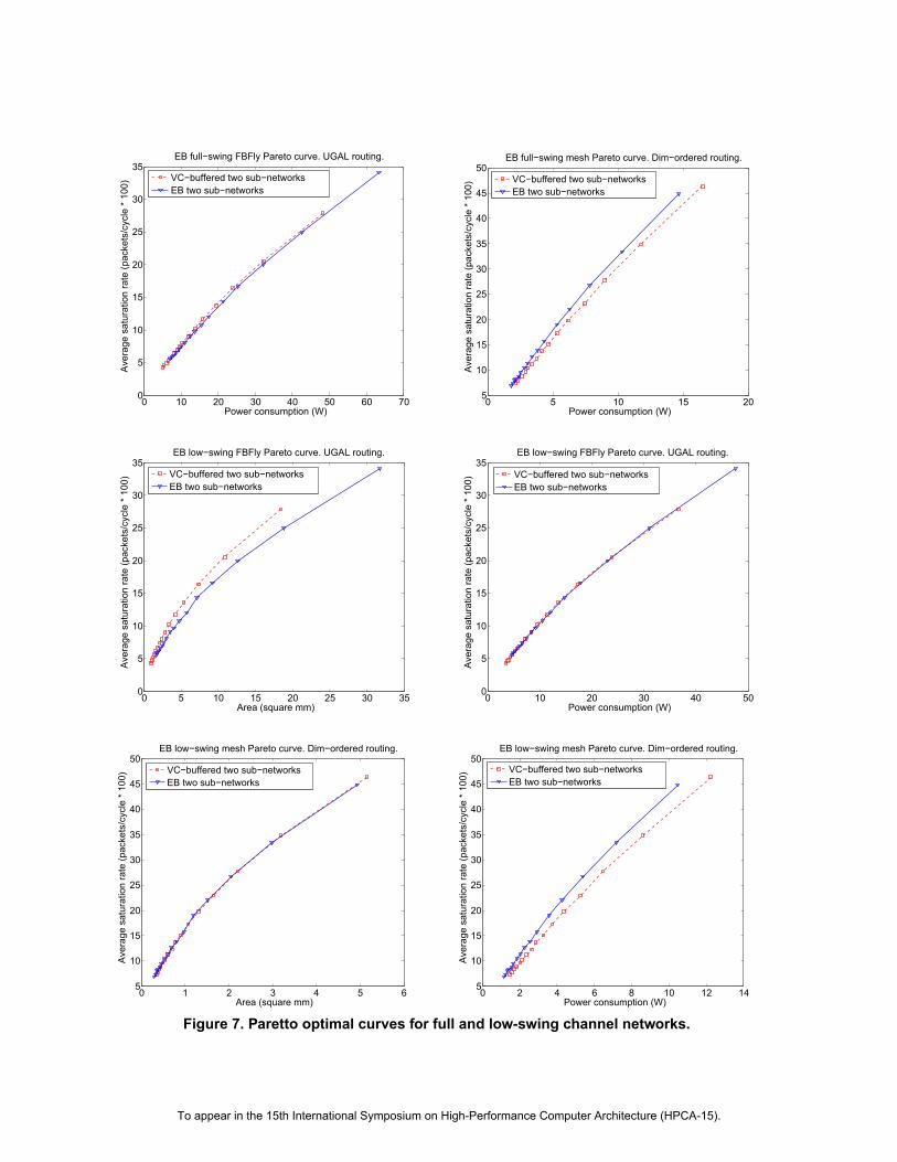
Figure 7 shows Pareto optimal curves for the FBFly andthe 2D mesh for full and low-swing channels. The curveswere generated by sweeping datapath width from 28 to 192bits in numbers divisible by the packet size. Points representan optimal design point, associating power consumptionand maximum throughput, or area and maximum through-put. Thus, they illustrate the characteristics of a networkwith a certain area, power or performance budget.Figure 8 presents throughput-latency curves for uniform
traffic and 64-bit channel widths. The VCN was configuredfor low-swing channels.Figure 9 shows an area and power breakdown, by net-
work component, for the full-swing model. Figure 10presents the same power breakdown for the low-swingmodel. All results are for a single DOR FBFly networkwith a 64-bit datapath under uniform random traffic, makingEBN and VCN flits traverse the same paths. This providesa fair comparison given the different congestion metrics forUGAL routing. Figure 11 presents a power breakdown forthe 2D mesh with low-swing wires, under a 2% packetinjection rate for uniform random traffic. VCB power is25% of the overall, compared to 21.5% for the DOR FBFly.Channel traversal refers to the power to traverse a segmentwith repeaters. For EBNs, input buffer read power is thetraversal power for the intermediate router register shownin Figure 2. Low-swing networks have the same area break-down except for the channel area which is doubled.Table 1 summarizes the percentage gains for each of the
two topologies. For each comparison, EBNs and VCNshave the metric shown in the first column equalized by ad-justing the EBN datapath width. The percentage gains com-pare VCNs and EBNs against the two other aspects. Thatpercentage is calculated by calculating the distance at eachsampling point between the Pareto curve that associateseach aspect under comparison with the normalized aspect,dividing by the value of the aspect under comparison, andaveraging among all sampling points. A positive percentagemeans that EBNs provide gains for that comparison, andthus the percentage was calculated against the aspect undercomparison value of VCNs. Likewise, negative percentagesindicate gains for VCNs.This section assumes a constant clock frequency, thus
ignoring EBN gains presented in section 5.
To appear in the 15th International Symposium on High-Performance Computer Architecture (HPCA-15).
0 10 20 30 40 50 60 700
5
10
15
20
25
30
35
Power consumption (W)
Ave
rage
sat
urat
ion
rate
(pac
kets
/cyc
le *
100
)
EB full−swing FBFly Pareto curve. UGAL routing.
VC−buffered two sub−networksEB two sub−networks
0 5 10 15 205
10
15
20
25
30
35
40
45
50
Power consumption (W)
Ave
rage
sat
urat
ion
rate
(pac
kets
/cyc
le *
100
)
EB full−swing mesh Pareto curve. Dim−ordered routing.
VC−buffered two sub−networksEB two sub−networks
0 5 10 15 20 25 30 350
5
10
15
20
25
30
35
Area (square mm)
Ave
rage
sat
urat
ion
rate
(pac
kets
/cyc
le *
100
)
EB low−swing FBFly Pareto curve. UGAL routing.
VC−buffered two sub−networksEB two sub−networks
0 10 20 30 40 500
5
10
15
20
25
30
35
Power consumption (W)
Ave
rage
sat
urat
ion
rate
(pac
kets
/cyc
le *
100
)EB low−swing FBFly Pareto curve. UGAL routing.
VC−buffered two sub−networksEB two sub−networks
0 1 2 3 4 5 65
10
15
20
25
30
35
40
45
50
Area (square mm)
Ave
rage
sat
urat
ion
rate
(pac
kets
/cyc
le *
100
)
EB low−swing mesh Pareto curve. Dim−ordered routing.
VC−buffered two sub−networksEB two sub−networks
0 2 4 6 8 10 12 145
10
15
20
25
30
35
40
45
50
Power consumption (W)
Ave
rage
sat
urat
ion
rate
(pac
kets
/cyc
le *
100
)
EB low−swing mesh Pareto curve. Dim−ordered routing.
VC−buffered two sub−networksEB two sub−networks
Figure 7. Paretto optimal curves for full and low-swing channel networks.
To appear in the 15th International Symposium on High-Performance Computer Architecture (HPCA-15).

0 2 4 6 8 10 120
20
40
60
80
100
120
140
Injection rate (packets/cycle * 100)
Ave
rage
late
ncy
(clo
ck c
ycle
s)Not normalized. FBFly, UGAL routing. Width = 64 bits.
VC−buffered two sub−networksEB two sub−networks
0 5 10 15 2020
40
60
80
100
120
140
160
Injection rate (packets/cycle * 100)
Ave
rage
late
ncy
(clo
ck c
ycle
s)
Not normalized. Mesh, dim−ordered routing. Width = 64 bits.
VC−buffered two sub−networksEB two sub−networks
Figure 8. Throughput-latency curves for uniform random traffic.
0 0.5 1 1.5 2 2.5
VC-Buff
EBN
Full-swing power breakdown (4% packet injection rate)
Output clock
Output FF
Crossbar control
Crossbar power
Input buffer write
Input buffer read
Channel FF
Channel clock
Channel traversal
(W)
0.0
0.2
0.4
0.6
0.8
1.0
1.2
VC-Buff EBN
Full-swing area breakdown
Channel Crossbar Input buffer Output
(mm2)
Figure 9. Cost breakdowns for a DOR FBFly with 64-bit full-swing channels under uniform traffic.
4 Discussion
As the results show, EBNs yield larger gains in a 2Dmesh. In a mesh, each flit takes many router hops, incur-ring buffering costs at each router. Thus, a flit in the meshnetwork consumes more energy to reach its final destinationthan a flit in the FBFly, and VCB energy is a more signif-icant portion. Therefore, 2D mesh EBNs exhibit greaterpower savings because more energy is consumed in theVCBs. The additional power consumed in the intermedi-ate EBN router pipeline register is much less than the inputVCB. These results demonstrate that topology, specificallyas it affects average hop counts, affects the gains that arerealized by EBNs.The dominant portion of the overall power for the full-
swing model is the power to traverse the repeated wiresin the channels. Low-swing channels reduce the overallpower, making VCB power a more significant portion ofthe overall network power. Therefore, EBNs yield a greaterpower improvement from removing VCBs in a network thatuses low-swing channels.Our analysis assumes efficient VCBs implemented with
Table 1. EBN Percentage gains.Norm DOR Mesh UGAL FBFlyComp: Area Perf Power Area Perf Power
Full-swingArea - 1% 7% - -10% 10%Perf 2% - 8% -20% - -3%Power -11% 8% - -16% -2% -
Low-swingArea - 2% 10% - -11% 15%Perf 2% - 12% -23% - 0%Power -15% 10% - -24% 0% -
SRAM cells. Latch or FF array implementations are less ef-ficient, increasing VCB overhead and making EBNs moreattractive. Doubling channel area due to differential wiringhas a small impact because the majority of the area is occu-pied by the router crossbar.EBNs consume less power compared to VCNs of the
same datapath width. To normalize EBNs and VCNs fora fixed power budget, we increase the EBN datapath width.In that case, EBNs can support a higher maximum through-put. Alternatively, we can normalize the two networks for
To appear in the 15th International Symposium on High-Performance Computer Architecture (HPCA-15).

0 0.2 0.4 0.6 0.8
VC-Buff
EBN
Low-swing power breakdown (4% packet injection rate)
Output clock
Output FF
Crossbar control
Crossbar power
Input buffer write
Input buffer read
Channel FF
Channel clock
Channel traversal
(W)Figure 10. Low-swing power breakdown.
0 0.2 0.4 0.6 0.8
VC-Buff
EBN
Mesh low-swing power breakdown (2% packet injection rate)
Output clock
Output FF
Crossbar control
Crossbar power
Input buffer write
Input buffer read
Channel FF
Channel clock
Channel traversal
(W)Figure 11. Mesh power breakdown.
the same maximum throughput by choosing another EBNdatapath width. In that case, EBNs can consume less power.Therefore, EBNs are more performance and power efficientcompared to VCNs. SRAM VCBs occupy a small amountof area. Thus, area normalization makes datapath widthsequal or almost equal, resulting in similar networks as bi-section bandwidth normalization.Due to the FIFO nature of EB channels, packets in
the same sub-network share the same resources. Thus, ablocked flit blocks all flits behind it, making EBNs moresensitive to contention. As a solution, more duplicate sub-networks can be provided. Consequently, quality of service(QoS) guarantees are only possible across sub-networks.Therefore, the effect of having VCBs in networks com-
pared to EBNs of the same datapath width is higher link uti-lization and maximum throughput with a higher maximumpower consumption, but with a favorable performance
power ratio.Designs that need the highest performance possible with afixed area budget should use VCNs. This is because theSRAM VCBs occupy little area, so removing them yieldsminimal area savings. However, increasing the datapathwidth increases the crossbar area quadratically.As explained in section 2.7, dividing the network into
sub-networks improves performance and power efficiency.However, this is only true up to a certain number of sub-networks. After that, each sub-network’s control over-head dominates and serialization latency becomes signifi-cant. Moreover, duplicating networks increases source anddestination network interface radix. Thus, for each network
configuration there is an optimal number of sub-networksfor performance and power efficiency. VCNs are a favor-able choice for complex protocols or adaptive routing algo-rithms requiring more sub-networks than that number.The amount of buffering in EB channels scales directly
with channel length, affecting EBN performance. Topolo-gies with double the channel length have an increased per-formance of 8-10% in the UGAL FBFly, but on the otherhand almost double the channel power for a total powerincrease of approximately 60%. Topologies with half thechannel length show a similar trend. VCN performance isaffected by the different size of VCBs, due to the differentround-trip time. The 2D mesh shows a similar trend. Thisshows that the dominant factor affecting maximum through-put in EBNs is the contention in the bufferless routers.However, designers might still find it beneficial to add stor-age slots in channels, as explained in section 2.1, dependingon their topology, layout and router radix.EB channels have the same zero-load latency when mea-
sured in clock cycles, since the ready-valid protocol de-scribed in section 2.1 does not add any latency. Moreover,the EB router described in section 2.2 consists of two stages,as the assumed VC router model. We also assume thatVCB depth is large enough to cover the credit processingand propagation delay. Zero-load latency in the EB UGALFBFly is increased by 3.3% by average, due to the extra hopvery few flits have to take, as explained in section 2.5. Asthe injection rate increases, latency increases in a similarmanner between EBNs and VCNs. However, EBNs satu-rate earlier for equal-width datapaths due to their sensitivityto contention. Datapath width affects serialization latencyand thus zero-load latency. In practice, as discussed in sec-tion 5, EBN routers are more likely to require fewer cyclesto traverse, or will operate at a higher clock frequency, dueto their simplified design.EBNs provide a higher throughput for the same power
budget, or consume less power for the same throughput.However, designs with strict area budgets which prioritizeperformance will find VCNs to be the preferable choice.Designs that need other features from the network shouldinvestigate how to implement those in EBNs and compareaccording to their priorities. Circuit techniques such as low-swing channels that reduce the power consumption of com-ponents outside the VCBs so that VCBs consume a greaterfraction of the overall power will favor the use of EBNs. Forfairness, this study uses SRAM-based VCBs, the most ef-ficient design. Using VCBs based on latches or FFs wouldsignificantly increase area and power, and hence EBN gains.
5 Router Implementation
An EBN router is much simpler than a correspondingVCN router. Table 2 shows a comparison of area, delay,
To appear in the 15th International Symposium on High-Performance Computer Architecture (HPCA-15).

Table 2. Router implementation comparison.Aspect VC router EB router# ports 703 683# nets 16202 5581# gates 60010 13917# cells 15943 4143Area (μm2) 63515 14730Cycle time (ns) 3.3 2.7Dyn. power (mW) 2.59 0.12
and power for 5 × 5 mesh routers implemented in a 45nmlow-power CMOS technology under worst-case conditions.The results were obtained by synthesizing the design usingSynopsys Design Compiler and placing and routing the syn-thesized design using Cadence Silicon Encounter. Powerwas measured from simulations using uniform random traf-fic and 24% flit injection rate in each router input, to avoidsaturating either router. Realistic router input and outputtiming constraints, loads and driving strengths were used.The VC router had 2 VCs of 8 buffer slots each. Routingpre-computation [8] was used. Due to library constraints,input buffers were implemented from FF arrays.Results show a 77% decrease in occupied area, an 18%
decrease in cycle time and a 95% decrease in dynamicpower. The reduced cycle time enables the network tobe clocked at a higher frequency, thus achieving a higherthroughput per absolute time, or a lower zero-load latencyif the pipeline stages in the VC router are increased.The cycle time of the EB router is constrained by the out-
put EB occupancy counters and read/write logic. The outputEB was implemented as a FIFO due to the high complex-ity of a three-slot FSM EB. We expect that optimizing theoutput EB will further decrease the EB cycle time.The VC router cycle time is constrained by the VC and
switch allocators. Increasing the number of VCs increasesthe complexity of the first stage.The 95% decrease in dynamic power is due to using FFs
to implement the VCBs, instead of SRAM cells.
6 Related Work
An alternative EB channel implementation is describedin [15]. Unlike our EB channels, those channels are un-pipelined and use repeater cells for storage rather thanlatches. Using repeater cells for storage adds transistors af-fecting the channel datapath.A hybrid VCB–EB scheme was explored in [13]. How-
ever, due to the FIFO nature of channels, the interleavingdeadlock, presented in section 2.6, can still occur. Prevent-ing it requires transmitting flits without a credit (which maybe stored in the EB channel) only if they are non-head, sig-nificantly limiting gains from using EB channels. For thesame reason, there is no isolation between flits of different
VCs. Blocked flits in EB channels block flits from otherVCs, even though there may be available buffer space in therouter. We have found such hybrid schemes to be beneficialonly for very small VCBs. However, such small VCBs rep-resent an inefficient design choice since they can be madelarger for a small power cost, but with a significant perfor-mance gain — assuming SRAM VCB implementations.Compressionless routing also does not use VCs [12]. It
relies on feedback from the network sent back to networkinterfaces. Time division circuit-switching flow-control hasalso been proposed [14]. Connection-based routing can alsobe used for deadlock-free adaptive routing [20] by allow-ing intermediate nodes to tear down and modify end-to-endvirtual circuits. A hybrid packet-connected circuit has alsobeen proposed, requiring the routers to have buffer spaceonly for request packets [21]. Bufferless networks can avoiddropping packets by emitting packets in a non-ideal direc-tion, also called deflective routing [17].The vast majority of NoC implementations focus on
packet switched networks with a per-input VCB scheme [3].Such networks enable easy deadlock avoidance, optimizedwire utilization, improved performance and QoS [2]. Thesecharacteristics along with a reasonable design complexitymake VCs the current dominant NoC flow-control schemeand VCNs the comparison metric for this work.
7 Conclusion
This work presented EBNs, an efficient NoC flow-control scheme. EBNs make use of already-existentpipeline FFs in channels for storage, using channels as dis-tributed FIFOs. The power gains from removing the VCBscan be spent on widening the EBN datapath, essentiallytrading VCBs for increased bandwidth, for networks with afixed power budget. Duplicate physical channels are usedinstead of VCs to prevent cyclic dependency and proto-col deadlocks. Dividing the network into sub-networks in-creases performance and power efficiency when normaliz-ing for a fixed performance or power budget.We compare a number of congestion sensing mech-
anisms for EBNs, and show that the output occupancymechanism provides the best performance. Using thiscongestion sensing mechanism, minimal and non-minimalsub-networks, and progressive adaptive routing, we applyUGAL routing to FBFly EBNs.For UGAL FBFly EBNs, performance and power effi-
ciency is almost equal in the low-swing model, with a 3%loss for EBNs in the full-swing case, compared to VCNs.EBN gains in 2D mesh networks reach 8% for the full-swing channel model, and 12% for the low-swing. Onthe other hand, due to having a wider datapath, EBNs oc-cupy more area when normalized for power or performance.Zero-load latency is equal between EBNs and VCNs of the
To appear in the 15th International Symposium on High-Performance Computer Architecture (HPCA-15).
same clock frequency.EB routers are considerably simpler due to the removal
of allocators, credits and other overhead, such as VC andpacket IDs. This results in an 18% reduced cycle time com-pared to VC routers for 5×5 mesh routers. This allowsEBNs to be clocked at a higher frequency, or reduces thezero-load latency if the VC router pipeline stages are in-creased to meet that frequency.For many power-constrained on-chip networks, EBNs
substantially increase network efficiency while at the sametime simplifying the router design.
Acknowledgments
This work was supported in part by the National ScienceFoundation under Grant CCF-0702341, in part by the Na-tional Security Agency under Contract H98230-08-C-0272,in part by the Semiconductor Research Corporation underGrant 2007-HJ-1591, in part by the Defense Advanced Re-search Projects Agency under contract FA8650-07-C-7726-P00001—monitored by the Air Force, in part by the RobertBosch Stanford Graduate Fellowship, and in part by the Ca-dence Design Systems Stanford Graduate Fellowship.
References
[1] James Balfour and William J. Dally. Design tradeoffs fortiled CMP on-chip networks. In ICS ’06: Proceedings of the20th annual International Conference on Supercomputing,pages 187–198, 2006.
[2] T. Bjerregaard and S. Mahadevan. A survey of researchand practices of network-on-chip. ACM Computing Surveys,38(1):1, 2006.
[3] William J. Dally. Virtual-channel flow control. IEEE Trans-actions on Parallel and Distributed Systems, 3(2):194–205,1992.
[4] William J. Dally and Hiromichi Aoki. Deadlock-free adap-tive routing in multicomputer networks using virtual chan-nels. IEEE Transanctions on Parallel and Distributed Sys-tems, 4(4):466–475, 1993.
[5] William J. Dally and Brian Towles. Route packets, not wires:On-chip interconnection networks. InDAC ’01: Proceedingsof the 38th Conference on Design Automation, pages 684–689, 2001.
[6] William J. Dally and Brian Towles. Principles and Practicesof Interconnection Networks. Morgan Kaufmann PublishersInc., San Francisco, CA, USA, 2003.
[7] Giovanni de Micheli and Luca Benini. Networks on chip:A new paradigm for systems on chip design. In DATE ’02:Proceedings of the conference on Design, Automation andTest in Europe, page 418, 2002.
[8] Mike Galles. Spider: A high-speed network interconnect.IEEE Micro, 17(1):34–39, 1997.
[9] Andreas Hansson, Kees Goossens, and Andrei Radulescu.Avoiding message-dependent deadlock in network-basedsystems on chip. VLSI Design, May 2007.
[10] Ron Ho, Ken Mai, and Mark Horowitz. Efficient on-chipglobal interconnects. In Symposium on VLSI Circuits, pages271–274, 2003.
[11] John Kim, William J. Dally, and Dennis Abts. Flattenedbutterfly: a cost-efficient topology for high-radix networks.In ISCA ’07: Proceedings of the 34th annual Interna-tional Symposium on Computer Architecture, pages 126–137, 2007.
[12] Jong H. Kim, Ziqiang Liu, and Andrew A. Chien. Compres-sionless routing: a framework for adaptive and fault-tolerantrouting. SIGARCHComputer Architecture News, 22(2):289–300, 1994.
[13] Avinash Kodi, Ashwini Sarathy, and Ahmed Louri. Designof adaptive communication channel buffers for low-powerarea-efficient network-on-chip architecture. In ANCS ’07:Proceedings of the 3rd ACM/IEEE Symposium on Architec-ture for Networking and Communications Systems, pages47–56, 2007.
[14] Jian Liu, Li-Rong Zheng, and H. Tenhunen. A guaranteed-throughput switch for network-on-chip. In Proceedings ofInternational Symposium on System-on-Chip, pages 31–34,2003.
[15] Masayuki Mizuno, , William J. Dally, and Hideaki Onishi.Elastic interconnects: repeater-inserted long wiring capableof compressing and decompressing data. In ISSCC ’01: Pro-ceedings of IEEE International Solid-State Circuits Confer-ence, pages 346–347, 464, 2001.
[16] Robert Mullins, Andrew West, and Simon Moore. Low-latency virtual-channel routers for on-chip networks. InISCA ’04: Proceedings of the 31st annual International Sym-posium on Computer Architecture, page 188, 2004.
[17] Erland Nilsson, Mikael Millberg, Johnny Oberg, and AxelJantsch. Load distribution with the proximity congestionawareness in a network on chip. In DATE ’03: Proceedingsof the conference on Design, Automation and Test in Europe,pages 1126–1127, 2003.
[18] Arjun Singh. Load-Balanced Routing in InterconnectionNetworks. PhD in electrical engineering, Stanford Univer-sity, 2005.
[19] Vladimir Stojanovic and Vojin G. Oklobdzija. Compara-tive analysis of master-slave latches and flip-flops for high-performance and low-power systems. IEEE Journal of Solid-State Circuits, 34(4):536–548, Apr 1999.
[20] Yoshio Turner and Yuval Tamir. Deadlock-free connection-based adaptive routing with dynamic virtual circuits. Journalof Parallel and Distributed Computing, 67(1):13–32, 2007.
[21] Daniel Wiklund and Dake Liu. SoCBUS: Switched network-on-chip for hard real time embedded systems. In IPDPS ’03:Proceedings of the 17th International Symposium on Paralleland Distributed Processing, page 78.1, 2003.
To appear in the 15th International Symposium on High-Performance Computer Architecture (HPCA-15).