EKT 221 / 4 DIGITAL ELECTRONICS II SUBJECT INTRODUCTION.
37
EKT 221 / 4 EKT 221 / 4 DIGITAL ELECTRONICS DIGITAL ELECTRONICS II II SUBJECT INTRODUCTION SUBJECT INTRODUCTION
-
Upload
francis-small -
Category
Documents
-
view
233 -
download
0
Transcript of EKT 221 / 4 DIGITAL ELECTRONICS II SUBJECT INTRODUCTION.

EKT 221 / 4EKT 221 / 4 DIGITAL ELECTRONICS II DIGITAL ELECTRONICS II
SUBJECT INTRODUCTIONSUBJECT INTRODUCTION
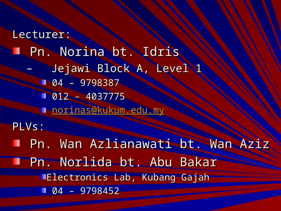
Lecturer:Lecturer:
Pn. Norina bt. IdrisPn. Norina bt. Idris– Jejawi Block A, Level 1Jejawi Block A, Level 1
04 – 979838704 – 9798387
012 – 4037775012 – 4037775
[email protected]@kukum.edu.my
PLVs:PLVs:
Pn. Wan Azlianawati bt. Wan AzizPn. Wan Azlianawati bt. Wan Aziz
Pn. Norlida bt. Abu BakarPn. Norlida bt. Abu BakarElectronics Lab, Kubang GajahElectronics Lab, Kubang Gajah
04 – 979845204 – 9798452

Grading:Grading:
50% - Final exam50% - Final exam
- Labs (Lab & Mini Project)- Labs (Lab & Mini Project)
50% - Tests 50% - Tests
- Tutorial/Assignment/Quizzes- Tutorial/Assignment/Quizzes

Main Text Book:Main Text Book:– Digital Electronics Digital Electronics
Design, Prentice Design, Prentice Hall.Hall.
– Price = RM 58.Price = RM 58.– Used in Digit I & Used in Digit I &
Digit II.Digit II.

Other References:Other References:
– Frank Vahid, Digital Design, John Wiley, Frank Vahid, Digital Design, John Wiley, 2007.2007.
– M. Morris Mano & Charles R. Kime, Logic M. Morris Mano & Charles R. Kime, Logic and Computer Design Fundamentals, 3and Computer Design Fundamentals, 3rdrd Edition, Prentice Hall.Edition, Prentice Hall.
– Floyd, Digital Fundamentals, Prentice Hall.Floyd, Digital Fundamentals, Prentice Hall.

Teaching PlanTeaching Plan

Chapter 0 : Combinational Logic Design Chapter 0 : Combinational Logic Design
RevisionRevision
CAD ToolsCAD Tools
Design ProcedureDesign Procedure
OUTLINEOUTLINE

Chapter 1 : Registers & Register TransfersChapter 1 : Registers & Register Transfers
Registers, Microoperations & ImplementationsRegisters, Microoperations & Implementations
Counters, register cells, buses & serial operationsCounters, register cells, buses & serial operations
CountersCounters
Register cell designRegister cell design
Multiplexer and bus-based transfers for multiple Multiplexer and bus-based transfers for multiple registersregisters
Serial transfers & microoperationsSerial transfers & microoperations
OUTLINEOUTLINE

Chapter 2 : Sequencing & ControlChapter 2 : Sequencing & Control
State machineState machineDatapath & controlDatapath & controlAlgorithmic State Machine (ASM)Algorithmic State Machine (ASM)Hardwired controlHardwired controlMicroprogrammed controlMicroprogrammed control
OUTLINEOUTLINE
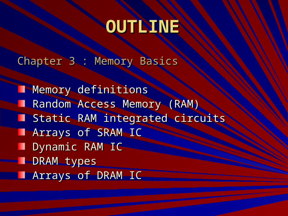
Chapter 3 : Memory BasicsChapter 3 : Memory Basics
Memory definitionsMemory definitionsRandom Access Memory (RAM)Random Access Memory (RAM)Static RAM integrated circuitsStatic RAM integrated circuitsArrays of SRAM ICArrays of SRAM ICDynamic RAM ICDynamic RAM ICDRAM typesDRAM typesArrays of DRAM ICArrays of DRAM IC
OUTLINEOUTLINE

Chapter 4 : Computer Design BasicsChapter 4 : Computer Design Basics
DatapathDatapath
OUTLINEOUTLINE

EXPERIMENTSEXPERIMENTS
Lab 1Lab 1 -- Introduction to MaxPlus II -- Introduction to MaxPlus II
Lab 2Lab 2 -- Introduction to UP2 Training -- Introduction to UP2 Training BoardBoard
Lab 3 Lab 3 -- Combinational System-- Combinational System
Lab 4Lab 4 -- Multiplier -- Multiplier
Lab 5Lab 5 -- Up-Down Counter -- Up-Down Counter
Lab 6Lab 6 -- Serial Multiplier (Part 1) -- Serial Multiplier (Part 1)
Lab 7 --Lab 7 -- Serial Multiplier (Part 2) Serial Multiplier (Part 2)
Lab 8Lab 8 -- State Machine (Moore Model) -- State Machine (Moore Model)

Course Outcomes (COs) Course Outcomes (COs)
CO1: CO1: Ability to design digital systems at the Ability to design digital systems at the
sub-system level. sub-system level.
CO2:CO2: Ability to use MaxPlus II design Ability to use MaxPlus II design software. software.
CO3: CO3: Ability to download the design software Ability to download the design software toto
FPGA device for testing purposes. FPGA device for testing purposes.
CO4: CO4: Ability to participate effectively in a team. Ability to participate effectively in a team.

What to expect & do … In ClassWhat to expect & do … In Class
To do:To do:– Sign up the attendance sheetSign up the attendance sheet– Do not be NOisY..Do not be NOisY..– Pay attentionPay attention
To expect:To expect:– Surprise quizzesSurprise quizzes– In-class assignmentsIn-class assignments

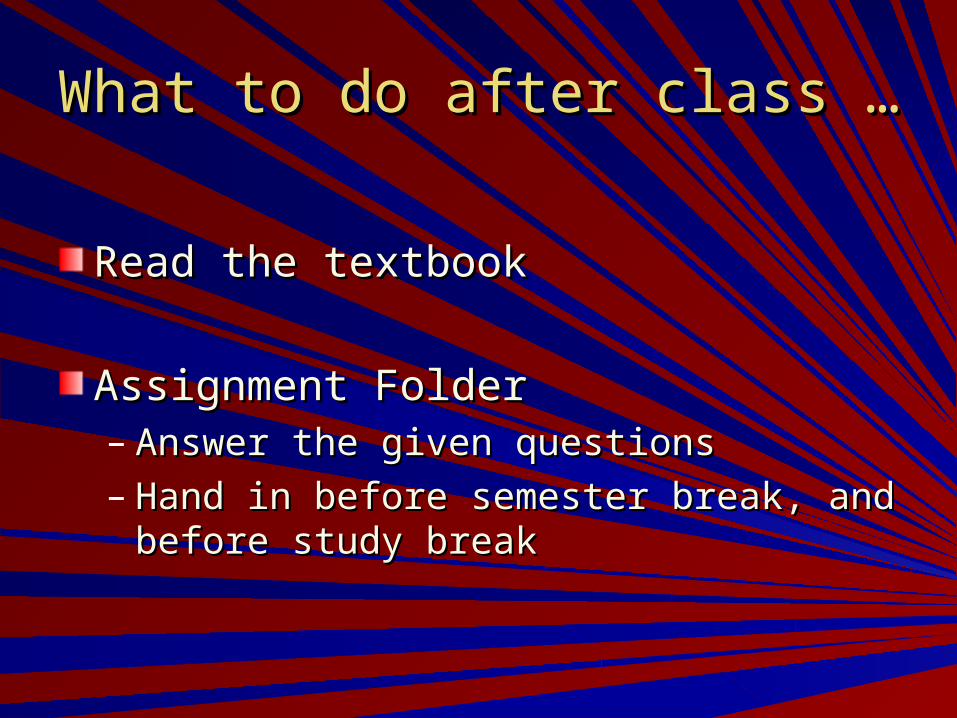
What to do after class …What to do after class …
Read the textbookRead the textbook
Assignment FolderAssignment Folder– Answer the given questionsAnswer the given questions– Hand in before semester break, and before Hand in before semester break, and before
study breakstudy break
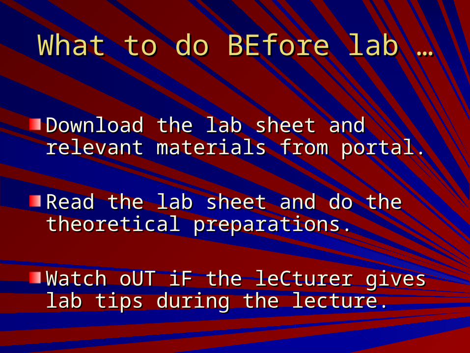
What to do BEfore lab …What to do BEfore lab …
Download the lab sheet and relevant Download the lab sheet and relevant materials from portal.materials from portal.
Read the lab sheet and do the theoretical Read the lab sheet and do the theoretical preparations.preparations.
Watch oUT iF the leCturer gives lab tips Watch oUT iF the leCturer gives lab tips during the lecture.during the lecture.
What to expect & do … In LabWhat to expect & do … In Lab
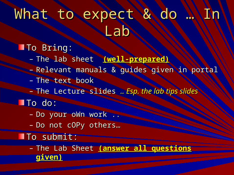
To Bring:To Bring:– The lab sheet The lab sheet (well-prepared)(well-prepared)– Relevant manuals & guides given in portalRelevant manuals & guides given in portal– The text bookThe text book– The Lecture slides The Lecture slides .. Esp. the lab tips slides.. Esp. the lab tips slides
To do:To do:– Do your oWn work ..Do your oWn work ..– Do not cOPy others…Do not cOPy others…
To submit:To submit:– The Lab Sheet The Lab Sheet (answer all questions given)(answer all questions given)

What to expect & do … In ClassWhat to expect & do … In Class
To do:To do:– Sign up the attendance sheetSign up the attendance sheet– Do not be NOisY..Do not be NOisY..– Pay attentionPay attention
To expect:To expect:– Surprise quizzesSurprise quizzes– In-class assignmentsIn-class assignments
What to do after class …What to do after class …
Read the textbookRead the textbook
Assignment FolderAssignment Folder– Answer the given questionsAnswer the given questions– Hand in before semester break, and before Hand in before semester break, and before
study breakstudy break

What to expect & do … In LabWhat to expect & do … In Lab
To do:To do:– Do your oWn work ..Do your oWn work ..– Do not cOPy others…Do not cOPy others…– Bring your own “test pen” and “IC extractor”Bring your own “test pen” and “IC extractor”– Submit the lab sheetSubmit the lab sheet
To expect:To expect:– Lab TestLab Test

The eND of sEmester cHallenGe…The eND of sEmester cHallenGe…
The mINI pRoJect…The mINI pRoJect…
The fiNaL eXaM…The fiNaL eXaM…
Study break coincides with the Hari Raya Study break coincides with the Hari Raya holidays.holidays.
soMe miNi pRoJect eXaMplessoMe miNi pRoJect eXaMples

Introduction to Lab 0Introduction to Lab 0
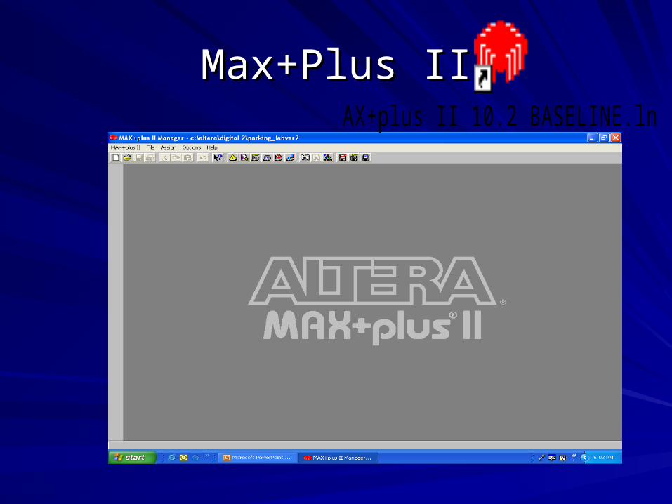
Max+Plus IIMax+Plus IIMAX+plus II 10.2 BASELINE.lnk

It is a Computer Aided It is a Computer Aided Design (CAD) tool to Design (CAD) tool to create logic circuits.create logic circuits.It can work on It can work on simulation through simulation through waveform generator waveform generator ORORIt can be It can be programmed/downloadprogrammed/downloaded to an Altera UP ed to an Altera UP (Univ. Prog.) board. (Univ. Prog.) board.
Max+Plus IIMax+Plus IIMAX+plus II 10.2 BASELINE.lnk
Connect using byte blaster cable

Altera Max+Plus IIAltera Max+Plus II
Altera UP-2 Training Board

Lab 0 : Intro to Max+Plus IILab 0 : Intro to Max+Plus II
Intro to Altera Max+Plus II softwareIntro to Altera Max+Plus II software
Understanding behavior of a basic logic circuitsUnderstanding behavior of a basic logic circuits
Analyze waveform simulationAnalyze waveform simulation

Lab 0 : Intro to Max+Plus IILab 0 : Intro to Max+Plus II
You will learn to:You will learn to:
Insert basic logic symbols using Graphic EditorInsert basic logic symbols using Graphic EditorUse of Max+Plus II libraryUse of Max+Plus II libraryUse 7 types of basic logic gates:Use 7 types of basic logic gates:– OR (OR2)OR (OR2)– AND (AND2)AND (AND2)– NOTNOT– NAND (NAND2)NAND (NAND2)– NOR (NOR2)NOR (NOR2)– XORXOR– XNOR XNOR
Use Input and Output PinsUse Input and Output PinsMake connectionsMake connectionsSimulate using Waveform EditorSimulate using Waveform EditorCreating Symbol from your logic gates designCreating Symbol from your logic gates design

Type of editor in Altera Type of editor in Altera Max+Plus IIMax+Plus II
In Lab0 you will learn to use:
1. Graphic Editor File2. Waveform Editor File
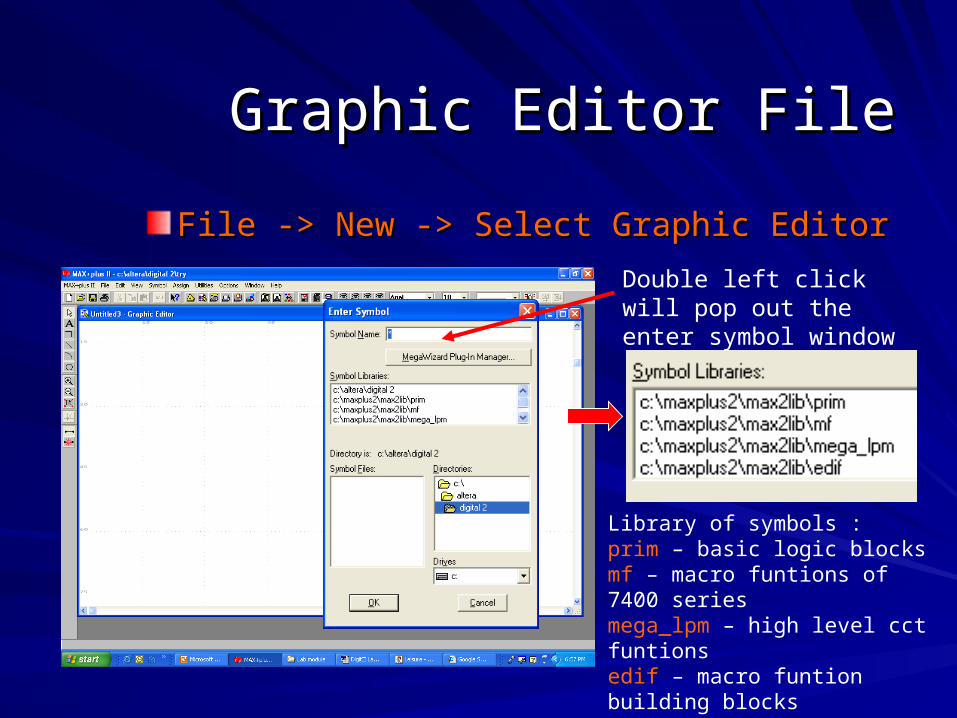
Graphic Editor FileGraphic Editor File
File -> New -> Select Graphic EditorFile -> New -> Select Graphic Editor
Library of symbols :prim – basic logic blocksmf – macro funtions of 7400 seriesmega_lpm – high level cct funtionsedif – macro funtion building blocks
Double left click will pop out the enter symbol window

Inserting Symbols from Inserting Symbols from the librarythe library
Please browse around to fimiliarize with all the symbols available in the library and check the symbol drawing representation

Your project should look something like thisYour project should look something like this

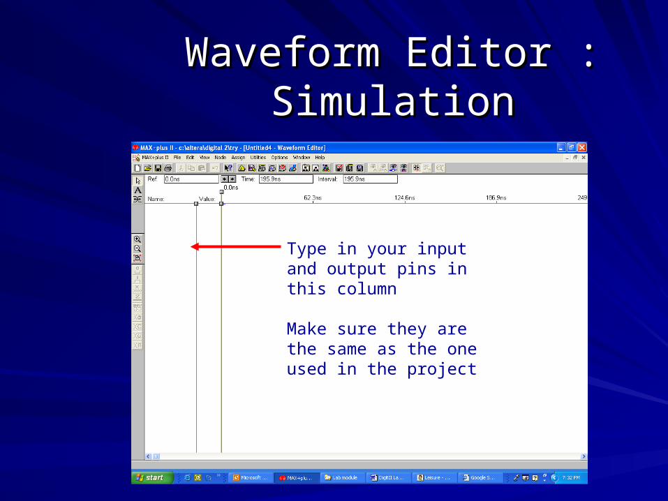
Waveform Editor : SimulationWaveform Editor : Simulation
Once you have finish designing using the Once you have finish designing using the Graphic EditorGraphic Editor
Open up the Waveform EditorOpen up the Waveform EditorFile -> New -> Select Waveform EditorFile -> New -> Select Waveform Editor
Adjust your End time and Grid SizeAdjust your End time and Grid SizeFile ->End timeFile ->End time (total length of simulation wave) (total length of simulation wave)
Options -> Grid SizeOptions -> Grid Size (interval)(interval)

How to determine End Time and How to determine End Time and Grid SizeGrid Size
Seconds (s)
Miliseconds (ms)
Miroseconds (us)
Nanoseconds (ns)
Considerations : no of input & cycle
Eg : 3 input and 1 cycle ; 000 to 111 = 8 levelsWe can use : End Time 8s and Grid Size 1sOr : End time 8ms and Grid 1msBUT is it practicle???
BEST case : End time 1ms and Grid 500us
OTHER EXAMPLES??
Waveform Editor : SimulationWaveform Editor : Simulation
Type in your input and output pins in this column
Make sure they are the same as the one used in the project
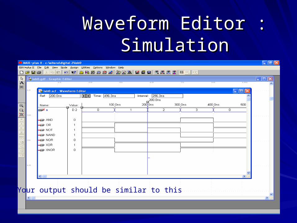
Waveform Editor : SimulationWaveform Editor : Simulation
Your output should be similar to this

WarningWarning
Make sure step 10, 11 and 12 is followedMake sure step 10, 11 and 12 is followed10 : 10 : File -> Project -> Save & CheckFile -> Project -> Save & Check
11 : 11 : Processing -> Functional SNF ExtractorProcessing -> Functional SNF Extractor
12 : 12 : File -> Project -> Save, Compile & SimulateFile -> Project -> Save, Compile & Simulate
Ensure also that lab0 project is set as current Ensure also that lab0 project is set as current project :project :File->Project -> Set project to current fileFile->Project -> Set project to current file


![EKT 2 2015 Question Paper Set G [Booklet Series G ...€¦ · EKT 2 2015 Question Paper Set G [Booklet Series G] Electrical & Electronics No .1 Defence Exam Prep Portal Visit : For](https://static.fdocuments.in/doc/165x107/5eae2f4d7477c65464577a15/ekt-2-2015-question-paper-set-g-booklet-series-g-ekt-2-2015-question-paper.jpg)