ekbdzksi zkslslj ij vk/kkfjr ,p - ,p- ih- Mhty bysfDVªd ª ... Draft_HHP... · based governor...
27
भा र त स र का र रे ल मं ा ल य अन ु सं धा न अ भ क प और मा न क सं ग ठ न लखनऊ था प त : 1957 © ekbdzksizkslslj ij vk/ yksdkse MICROPROCES DIESEL ELECTRI Specification Number MP.0.17 Revision Number 0 –d1 Brief Description This document describes the r Based Control Governor for Die details the functional requireme equipment ensuring reliability an Government of In Ministry of Railw Research Desig Standards Organizatio LUCKNO ESTT: 19 5 © RDSO 2014 /kkfjr ,p- ,p- ih- Mhty bysfD eksfVo ds fy, xouZj SSOR BASED GOVERNO FOR IC LOCOMOTIVES (HHP) 700.05 Date of Issue 30/0 requirements for the development of Microp esel Electric Locomotives. The complete spe ent of the unit, scope of supply and testin nd fail -safe operation ndia ways gns & s on W 57 DVªd OR ) 06/2014 processor ecification ng of the
Transcript of ekbdzksi zkslslj ij vk/kkfjr ,p - ,p- ih- Mhty bysfDVªd ª ... Draft_HHP... · based governor...
भा र त स र का र रे ल मं ा ल य
अनु सं धा न अ भक प और मानक सं गठन
लखनऊ था प त : 1 9 5 7
© RDSO
ekbdzksizkslslj ij vk/kkfjr ,pyksdkseksfVo ds fy, xouZj
MICROPROCESSOR BASED
DIESEL ELECTRIC LOCO
Specification Number MP.0.1700.05Revision Number 0 –d1 Brief Description This document describes the requirements for the development of Microprocessor Based Control Governor for Diesel Electric Locomotives. The complete specification details the functional requirement of the unit, scope of supply and testing of the equipment ensuring reliability and fail
Government of IndiaMinistry of Railways
Research DesignStandards
OrganizationL U C K N O WE S T T : 1 9 5 7
© RDSO 2014
ekbdzksizkslslj ij vk/kkfjr ,p- ,p- ih- Mhty bysfDVªd yksdkseksfVo ds fy, xouZj
MICROPROCESSOR BASED GOVERNOR FOR
DIESEL ELECTRIC LOCOMOTIVES (HHP)
MP.0.1700.05
Date of Issue 30/06/2014
This document describes the requirements for the development of Microprocessor Based Control Governor for Diesel Electric Locomotives. The complete specification
functional requirement of the unit, scope of supply and testing of the equipment ensuring reliability and fail-safe operation
Government of India Ministry of Railways
Designs & Standards
Organization L U C K N O W
5 7
Mhty bysfDVªd
GOVERNOR
MOTIVES (HHP)
/06/2014
This document describes the requirements for the development of Microprocessor Based Control Governor for Diesel Electric Locomotives. The complete specification
functional requirement of the unit, scope of supply and testing of the

FOREWORD
Microprocessor Based Governor System (MPBG) enables Notch wise speed control of the Engine, Load control function in case of engine over load and provide other safety feature for satisfactory performance of Engine. MPBG shall display the relevant engine parameters along with the fault display, fault logging and downloading the logged data for analysis. This document specifies the requirements, testing and evaluation criteria of micro processor based governor (MPBG) suitable for all WDG4/WDP4 type HHP diesel electric locomotives for Indian Railways The specification of the MPBG is for standalone type. After gaining the experience in standalone MPBG, communication protocol will be developed for display all the messages in the Common display unit DIALS and the date and time sharing through Loco Control Computer (LCC) and will be incorporated in next update of the specification.
DISCLAIMER
This specification is based on the studies and trials conducted by RDSO. Although every care is taken in specifying details adequately and unambiguously, RDSO shall not liable for any kind of damages / losses incurred by any and all due to errors or omissions in this document. When using the information described herein, the user is ultimately responsible for their own actions, as well as the actions of subordinates and assistants, and the consequences arising there from.
This document may mention numerous commercial and proprietary trade names, registered trademarks and the like (not necessarily marked as such), patents, production and manufacturing procedures, registered designs, and designations. RDSO wishes to point out very clearly that the present legal situation in respect of these names or designations or trademarks must be carefully examined before making any commercial use of the same.
Names of industrially produced apparatus and equipment may be included to a necessarily restricted extent only and any exclusion of products not mentioned in this document does not imply that any such exclusion has been based on quality criteria or any other qualifying consideration.
COPYRIGHT
RDSO has the copyright of all its publications. No part of these publications may be reproduced in any form without the prior permission of RDSO. Enquires relating to the copyright should be addressed to Executive Director (Administration), RDSO.
ADDRESS FOR COMMUNICATION
Government of India - Ministry of Railways, Research Designs & Standards Organization Manak Nagar Lucknow Uttar Pradesh India Pin: 226 011 Fax: +91 (522) 2458500 Phone: +91 (522) 2451200 (PBX) +91 (522) 2450115 (DID) Website: www.rdso.indianrailways.gov.in

Document No: MP.0.1700.05 Revision No: 0-d1 Date Issued: 30/06/2014 Specification Title: Specification for MPBG for application on WDG4/WDP4 series Diesel Electric Locomotives (HHP)
INDIAN RAILWAYS, RESEARCH DESIGNS & STANDARDS ORGANIZATION Printed: 2014/06/30 Page 1 of 25
LIST OF AMENDMENTS S. No. Amendment Date Version Details
1.
Document No: MP.0.1700.05 Revision No: 0-d1 Date Issued: 30/06/2014 Specification Title: Specification for MPBG for application on WDG4/WDP4 series Diesel Electric Locomotives (HHP)
INDIAN RAILWAYS, RESEARCH DESIGNS & STANDARDS ORGANIZATION Printed: 2014/06/30 Page 2 of 25
CONTENTS 0 Background ........................................................................................................................................... 4 1 Objectives ............................................................................................................................................. 4 2 Scope of supply ..................................................................................................................................... 4 3 Terms and abbreviations....................................................................................................................... 4 4 General requirements ........................................................................................................................... 5
4.1 Manufacturers qualification ........................................................................................................... 5 4.2 Equipment Requirements.............................................................................................................. 5
5 Environmental/Climatic requirements ................................................................................................... 5 6 Functional requirements........................................................................................................................ 5
6.1 Speed Control ............................................................................................................................... 5 6.2 Speed Stability .............................................................................................................................. 6 6.3 Governor Response: ..................................................................................................................... 6 6.4 Load Control: ................................................................................................................................. 6
7 AUXILIARY FEATURES ....................................................................................................................... 6 7.1 Air Manifold Pressure Bias Fuel Limiter: ....................................................................................... 6 7.2 Engine over Speed Trip Facility: ................................................................................................... 7 7.3 Status Display of Engine Parameters: .......................................................................................... 7 7.4 Fuel oil Pressure (FOP) Transducer ............................................................................................. 7 7.5 Lube Oil Pressure (LOP) Transducer ........................................................................................... 7 7.6 Real-time clock .............................................................................................................................. 8
8 Safety Features/Devices ....................................................................................................................... 8 8.1 Low Lube Oil Pressure Shut-Down (LOPS) .................................................................................. 8 8.2 Low Water Pressure Shut-down ................................................................................................... 8 8.3 Positive Crankcase Pressure Shut-down...................................................................................... 8 8.4 Hot Engine Shut-down .................................................................................................................. 8 8.5 Fail-safe Feature ........................................................................................................................... 9
9 Diagnostic and Fault Logging System .................................................................................................. 9 10 Adjustment of Various Engine Parameters ....................................................................................... 9
10.1 Software: ....................................................................................................................................... 9 11 Governor Output Shaft and Linkage ................................................................................................. 9
11.1 Stroke: ........................................................................................................................................... 9 11.2 Work Capacity: ............................................................................................................................ 10
12 Mounting Arrangement.................................................................................................................... 10 12.1 Control cum Display unit: ............................................................................................................ 10 12.2 Actuator unit: ............................................................................................................................... 10 12.3 Pressure sensor box: .................................................................................................................. 10 12.4 Engine Speed Sensors ............................................................................................................... 10 12.5 Numbering ................................................................................................................................... 10
13 Applicable drawings ...................................................................................................................... 10 14 Referred standards ......................................................................................................................... 11 15 Maintenance and diagnostic aid ..................................................................................................... 11 16 Documents required from supplier .................................................................................................. 11 17 Warranty .......................................................................................................................................... 11 18 Training ........................................................................................................................................... 11 19 Tests & Verification ......................................................................................................................... 12 20 Sampling plan ................................................................................................................................. 12 21 Types of tests .................................................................................................................................. 12
21.1 Type test and field trials: ............................................................................................................. 12 21.2 Field trial ...................................................................................................................................... 12 21.3 Makers test certificate for outsourced item ................................................................................. 12
22 Painting, labeling and marking ........................................................................................................ 13 23 Packaging and delivery/shipment ................................................................................................... 13 24 IPR disclaimer pin pointing responsibility for violation if any on supplier ........................................ 13
24.1 Undertaking by equipment manufacturer .................................................................................... 13 24.2 Declaration of confidentiality of submitted documents by manufacturers ................................... 13 • Acceptance test ............................................................................................................................... 21
LIST OF TABLES

Document No: MP.0.1700.05 Revision No: 0-d1 Date Issued: 30/06/2014 Specification Title: Specification for MPBG for application on WDG4/WDP4 series Diesel Electric Locomotives (HHP)
INDIAN RAILWAYS, RESEARCH DESIGNS & STANDARDS ORGANIZATION Printed: 2014/06/30 Page 3 of 25
Table 1 5 Table 2 8 LIST OF REFERENCED DOCUMENTS
S. No. Document name / number 1. IEC 60571 2. IEC 60812 3. IEC 60529 4. IEC 62262 5. IS 2500 6. EDPS 179 7. MP. 0. 2400.43 (Latest) for AC - AC traction system for 4500HP WDG-4/WDP-4B
Diesel - Electric Locomotives LIST OF ANNEXURES Annexure 1 Details of cables Annexure 2 Governor Housing (Part no. 8163123) Annexure 2A Governor Control Linkage Annexure 2B Proposed Mounting Details of Engine Speed Sensor Annexure 3 Methodology for Inspection and testing of MPBG Annexure 4 Infrastructure Requirements for MPBG Manufacturers Annexure 5 List of Display Messages in Control unit of MPBG

Document No: MP.0.1700.05 Revision No: 0-d1 Date Issued: 30/06/2014 Specification Title: Specification for MPBG for application on WDG4/WDP4 series Diesel Electric Locomotives (HHP)
INDIAN RAILWAYS, RESEARCH DESIGNS & STANDARDS ORGANIZATION Printed: 2014/06/30 Page 4 of 25
0 Background The micro processor based governor (MPBG) is perceived as an alternative to Electro Hydraulic Governor for simpler maintenance with modular system and minimum moving parts, complete flexibility in various adjustments like engine speed, notch wise low lube oil shut down pressure and maximum allowable fuel rack as a function of engine notch position and booster air pressure.
1 Objectives The function of the Micro Processor Based Governor (MPBG) is Notch wise speed control of the Engine, Load control function in case of over load on the engine and also to provide other safety feature for satisfactory performance of Engine.
This document specifies the requirements, testing and evaluation criteria of micro processor based governor (MPBG) system suitable for all WDG4/WDP4 type HHP diesel electric locomotives for Indian Railways.
The scope shall also include necessary engineering design for retrofitting the proposed micro processor based governor (MPBG) on the existing engine. The system shall display the relevant engine parameters along with the fault display, fault logging and downloading the logged data for analysis. The system parameters limits shall be user settable.
The micro processor based governor (MPBG) would need to have prototype approval, prove-out, field trials and bulk supplies thereafter.
2 Scope of supply The deliverables to this specification for MPBG shall include:
i. Control cum Display unit along with mounting accessories.
ii. Actuator unit along with mounting accessories.
iii. Pressure sensor box along with mounting accessories.
iv. Engine Speed sensors - 02 nos. along with mounting accessories.
v. Interconnecting cables with connectors as per Annexure- 1.
All control cables shall be governed by EDPS-179.
3 Terms and abbreviations S. No Term /
Abbreviation Description
1. DLW Diesel Locomotive Works, Varanasi 2. DLMW Diesel Loco Modernisation Works 3. LCC Locomotive Control Computer 4. MBCS Microprocessor Based Control System 5. PU Production Units 6. RDSO Research Designs & Standards Organisation 7. ZR Zonal Railways 8. EPD Engine Protection Device 9. EDPS Engineering Design Performance specification

Document No: MP.0.1700.05 Revision No: 0-d1 Date Issued: 30/06/2014 Specification Title: Specification for MPBG for application on WDG4/WDP4 series Diesel Electric Locomotives (HHP)
INDIAN RAILWAYS, RESEARCH DESIGNS & STANDARDS ORGANIZATION Printed: 2014/06/30 Page 5 of 25
4 General requirements
4.1 Manufacturers qualification The manufacturer of the equipment shall be a reputed organization dealing with manufacture / integration of electronic systems. The manufacturer shall be capable of providing spares and support services during the operational life of the equipment from setups located within the international boundaries of the India.
4.2 Equipment Requirements The equipment supplied against this specification shall meet the following general requirements.
4.2.1. The equipment shall be designed for installation on diesel electric locomotives. The equipment manufacturer shall get the equipment design approved by RDSO before fitment on locomotives.
4.2.2. The equipment supplied shall be of good quality, rugged and reliable and capable to withstand environmental and use conditions. The individual components shall meet the lifecycle requirements for that category of equipment.
4.2.3. The offered MPBG shall be retrofittable with the existing woodward governor. The MPBG shall be accommodated in the existing envelope. Envelope is intended to mean the space available within the existing superstructure and existing accessory connections.
4.2.4. Wherever outsourced equipment is used, care shall be taken to ensure that the equipment is sourced from reputed manufacturers.
4.2.5. The supplier of equipment supplied under this specification shall ensure proper interfacing and connectivity between equipment / software.
4.2.6. Failure Mode Effects and Criticality Analysis of the equipment shall be done during the design process in conformance to IEC 60812. The records of this analysis shall be provided upon requirement.
4.2.7. The availability of the offered MPBG shall be minimum 90 days before any attention is paid to the power pack.
4.2.8. The supplier shall have a plan for indigenization of MPBG.
4.2.9. Existing Alternator, power pack and controls shall be used. In case modified, it becomes the part of the scope of supply of the supplier for the modifications / additions based on optimising the asset so that maximum gains can be achieved.
5 Environmental/Climatic requirements The equipment shall be tested as per the environmental requirements of IEC 60571(Latest).
6 Functional requirements The MPBG supplier must meet the following requirements of the existing governor fitted on WDG4/ WDP4 type HHP diesel electric loco
6.1 Speed Control The MPBG shall maintain eight engine speeds according to the steps commonly, called Notches. To maintain the required engine speed according to notch input is given in a particular sequence of electrical signal by MBCS/LCC as shown in the Table-1 given below. It shall have provision of user settable provision to alter engine speed at any notch, to suit the requirement arisen from fuel economy or engine performance considerations. Drop-out voltage of relays if provided, at notch input signals shall be within 15-18 Volts & pick-up Voltage shall be above 30 Volts.
Table 1 Notch Position
Wires Energised
Engine Speed (Rpm) Free from hunting with or without Load for 4000 HP
Engine Speed (Rpm) Free from hunting with or without Load for 4500 HP
Shut-Down 3 0 0

Document No: MP.0.1700.05 Revision No: 0-d1 Date Issued: 30/06/2014 Specification Title: Specification for MPBG for application on WDG4/WDP4 series Diesel Electric Locomotives (HHP)
INDIAN RAILWAYS, RESEARCH DESIGNS & STANDARDS ORGANIZATION Printed: 2014/06/30 Page 6 of 25
Low Idle 15,3 200 200 Idle/1 - 269 269 2 15 343 354 3 7 490 486 4 15, 7 568 572 5 12, 7, 3 651 675 6 15,12, 7, 3 729 764 7 12, 7 820 863 8 15,12, 7 904 954
6.2 Speed Stability MPBG is required to maintain stable engine speed i.e. free from hunting at each notch position in both conditions - with or without load.
6.3 Governor Response: Time taken for speed adjustment from IDLE to FULL speed shall be of the order of 15-20 seconds. For intermediate notch positions, the time taken to adjust engine RPM shall be in the same proportion.
6.4 Load Control: The MPBG shall generate the Load control output voltage signal to interface with Microprocessor Control system. This signal shall be in the form of Analog voltage which varies from 74 to 0 volts DC. In Engine normal condition the LCP output voltage is 74 volts and in Engine overload condition the LCP should vary from 74 volts to 0 volts to reduce the load on the Engine through Microprocessor Control system. MPBG shall be capable of load control and fuel limiting w.r.t BAP.
6.4.1 Supply Ratings: Voltage.............................. 74+1 V DC Current............................... 0.5 Amps.
6.4.2 Load Control Timing: a. Load control timing from maximum to minimum field position change shall be 5 – 9 seconds.
b. Load control timing from minimum to maximum field position change shall be 5 – 9 seconds.
7 AUXILIARY FEATURES The MPBG offered shall cater for the following auxiliary features:-
7.1 Air Manifold Pressure Bias Fuel Limiter:
The MPBG shall regulate the movement of fuel control shaft as a function of absolute air manifold pressure (boost air pressure). The MPBG shall satisfy the load limit requirements for 4000 HP/4500 HP locomotives. The system shall however, have the facility of fuel limit adjustment to any other fuel limit curve, if required.
7.1.1 Boost Air Pressure (BAP) transducer: Requirements of Boost air pressure transducer will be:
• Working range : 0 to 3.5 kg/cm² • Temperature of Boost air: 120ºC max.

Document No: MP.0.1700.05 Revision No: 0-d1 Date Issued: 30/06/2014 Specification Title: Specification for MPBG for application on WDG4/WDP4 series Diesel Electric Locomotives (HHP)
INDIAN RAILWAYS, RESEARCH DESIGNS & STANDARDS ORGANIZATION Printed: 2014/06/30 Page 7 of 25
7.2 Engine over Speed Trip Facility:
MPBG shall shut down the engine in the event of engine RPM increase beyond the set limit. Engine shut down RPM setting shall be user settable.
7.2.1 Mechanical and Electronic Engine over Speed Trip-Test Facility: MPBG shall have facility to slowly increase the engine speed above its rated speed for checking the setting of the mechanical over speed trip mechanism and over speed trip function of MPBG. It shall be possible to easily revert back to the normal setting of engine speeds in the event of Mechanical OSTA and Electronic OST test failed.
7.3 Status Display of Engine Parameters:
7.3.1 General requirements An industrial robust display shall be provided on the controller unit. The display shall be such that it is clearly visible under day and night conditions from a distance of 2 metre.
7.3.2 Typical requirements: The display shall either be a) A bluish green vacuum fluorescent display (VFD) with four lines of 20 characters of 5 mm each.
or b) Graphic colour LCD operator interface terminal with QVGA display and touch screen to the following specification:
• Typical power 8W • Battery: Lithium coin cell. Typical lifetime of 10 years • LCD Display
Size/Type 5.7 inch/STN Colours/ Pixels 256/320X240 Brightness/ Backlight 165 cd/m2/20,000 hr typ.
• 5-key keypad: for on-screen menus or Capacitive/resistive suitable for use on locomotives.
or c) OLED with four lines of 20 characters
• On board user memory: Minimum 32 MB non-volatile flash memory • USB port: USB 2.0, Minimum1 No. (Preferred 2 Nos.)
The display shall be in the format given below: LOP (kg/cm2) FOP (kg/cm2) BAP(kg/cm2) L . L F . F B . B B N S S S S R R . R H H : M M NOTCH ENGINE FUEL RACK LCP (hrs:minutes) SPEED (rpm) (degree)
7.4 Fuel oil Pressure (FOP) Transducer Requirements of Fuel oil pressure transducer will be as under:
• Working range : 0 to 5 Kg/cm2 • Temperature of Fuel oil : 55ºC max.
7.5 Lube Oil Pressure (LOP) Transducer Requirements of Lube oil pressure transducer will be as under:
• Working range : 0 to 10 Kg/cm2 • Temperature of Engine Lubricating oil : 125º C max.

Document No: MP.0.1700.05 Revision No: 0-d1 Date Issued: 30/06/2014 Specification Title: Specification for MPBG for application on WDG4/WDP4 series Diesel Electric Locomotives (HHP)
INDIAN RAILWAYS, RESEARCH DESIGNS & STANDARDS ORGANIZATION Printed: 2014/06/30 Page 8 of 25
7.6 Real-time clock The system shall have a real-time clock with accuracy of better than +/- 5 seconds over 30 days. The RTC shall be capable of time synchronization through laptop/ Display. The battery of RTC Clock should work for minimum 3 years and should be replaceable easily. Time synchronization through Laptop/Display based on Password protection should be provided.
8 Safety Features/Devices Provision shall be kept for the following safety features/devices in the MPBG being offered.
8.1 Low Lube Oil Pressure Shut-Down (LOPS) A safety feature to protect the engine in the event of low lube oil pressure shall be provided to shut down the engine, whenever the lube oil pressure falls below the following stipulated limits:
Table 2 Notch Engine Low Lop Settings (kg/cm²) Low Idle 0.5 kg/cm² Idle 0.9 kg/cm² 1 0.9 kg/cm² 2 1.1 kg/cm² 3 1.4 kg/cm² 4 1.7 kg/cm² 5 2.1 kg/cm² 6 2.7 kg/cm² 7 3.0 kg/cm² 8 3.3 kg/cm²
LOPS setting values are tentative and shall be user settable. It shall be possible to delay the operation of this device at each notch position. The governor shall also have a provision for adjustment of the LOPS setting values independently at each notch position. In the event of locomotive engine shutting down due to low lube oil pressure on affecting the low idle feature, the MPBG shall log the fault as “Engine Shut Down due to Low LOP at Low Idle”.
8.1.1 Time Delay Feature A time delay of 50 – 60 seconds shall be provided in low oil pressure shut down, system at idle/notch-1 speed steps to enable the engine driven lube oil pump to build up the requisite lube oil system pressure while starting the engine. It shall be possible to provide time delay facility at other notches as well. This time delay can be different for different notches
8.2 Low Water Pressure Shut-down A safety feature to protect the engine in the event of low water pressure shall be provided to shut down the engine. This Low water pressure shut-down feature by MPBG is by sensing the Lube oil pressure of the engine from the outlet of Engine Protective device, i.e. in the Locomotive in the event of Low water pressure the Engine protective device (EDP) will drain the Lube oil pressure which is going to Governor and the Governor will shut-down the engine due to Low lube oil pressure. The Low Lube oil pressure shut-down limits are given in Clause No: 8.1.
8.3 Positive Crankcase Pressure Shut-down A safety feature to protect the engine in the event of Positive crank case pressure in the engine shall be provided to shut-down the engine. This positive crank case pressure shut-down feature by MPBG, is by sensing the Lube oil pressure of the engine from the outlet of Engine Protective device, i.e. in the Locomotive in the event of Positive crank case pressure the Engine protective device will drain the Lube oil pressure which is going to Governor and the Governor shall shut-down the engine due to Low lube oil pressure. The Low Lube oil pressure shut-down limits are given in Clause No 8.1.
8.4 Hot Engine Shut-down A safety feature to protect the engine in the event of Hot engine shall be provided to shut down the engine. This Hot engine shut-down feature by MPBG is by sensing the Lube oil pressure of the engine

Document No: MP.0.1700.05 Revision No: 0-d1 Date Issued: 30/06/2014 Specification Title: Specification for MPBG for application on WDG4/WDP4 series Diesel Electric Locomotives (HHP)
INDIAN RAILWAYS, RESEARCH DESIGNS & STANDARDS ORGANIZATION Printed: 2014/06/30 Page 9 of 25
from the outlet of Engine Protective device i.e. in the Locomotive in the event of Hot engine the device Thermostat valve will open and drain the Lube oil pressure which is going to Governor and the Governor will shut-down the engine due to Low lube oil pressure. The Low Lube oil pressure shut-down limits are given in Clause No: 8.1.
8.5 Fail-safe Feature The MPBG shall be provided with fail-safe feature so as to cause shut-down of the diesel engine by pulling the fuel rack to “NO FUEL” position in the event of malfunctioning of the governing equipment eg. a) Power Supply Failure b) Control card failure c) LOP sensor Failure d) Load control failure e) Any other card failure / internal failure, etc.
9 Diagnostic and Fault Logging System 9.1. The MPBG offered shall include suitable fault diagnostic facility to carry out troubleshooting and to
assist maintenance personnel in the rectification of the defect/ defects.
9.2. Suitable memory to register Fault messages (Error Log) with Date and time stamp and their retrieval on a Laptop/Personal Computer/ Pen Drive and analysing through Fault Data Analysis software. A facility shall be provided to set the current date and time in the MPBG.
9.3. Suitable memory to register the Fault Data pack i.e. fault along with the status of MPBG parameters shall be provided. This fault data pack shall be of 30 seconds with one second interval for retrieval on a Lap Tap/Personal Computer/ Pen Drive and analysing through Fault Data Analysis software.
9.4. Recording of time spent on each notch shall be made in 24 hours format. The sampling interval should not be more than one second. This is required for calculation of load factor of locomotives. For this purpose eight counters shall be provided in MPBG memory for cumulative time spent on each notch in seconds. There should be a provision to read these counters through a Laptop/Personal computer any time to get the cumulative time spent on each of the 8 notches. All these counters should be capable of being reset to zero, at any time, through a Laptop/Personal computer.
10 Adjustment of Various Engine Parameters A simple arrangement shall be provided in the software to adjust the following parameters on the locomotive.
a. Notch wise engine speed b. Notch wise minimum lube oil pressure for loco shut down c. Maximum permissible fuel rack limit at each notch d. Maximum permissible fuel rack limit in relation to booster air pressure e. Over speed trip setting f. Governor response time g. Load control timing from max to min. field position of LCP & min. to max. field position of LCP.
These adjustments should be possible with a laptop/personal computer running in windows environment. A provision shall be made to restrict accessibility to governor adjustments to avoid misuse. All the relevant parameters shall be configurable through Laptop with two tier password protection based on sensitivity of parameter setting.
10.1 Software: Necessary software for adjusting the user settable parameters of the MPBG shall be provided.
11 Governor Output Shaft and Linkage
11.1 Stroke: The governor output shaft travel shall be of a rotary and the total rack travel in MPBG shall be maximum 30 degrees.
Document No: MP.0.1700.05 Revision No: 0-d1 Date Issued: 30/06/2014 Specification Title: Specification for MPBG for application on WDG4/WDP4 series Diesel Electric Locomotives (HHP)
INDIAN RAILWAYS, RESEARCH DESIGNS & STANDARDS ORGANIZATION Printed: 2014/06/30 Page 10 of 25
11.2 Work Capacity: The work capacity on the governor output shaft for actuation of fuel control shaft shall be at least 16.3 Nm (12 ft Ib).
12 Mounting Arrangement
12.1 Control cum Display unit: The Control unit cum Display unit shall be suitably mounted in the Driver’s cabin. List of messages to be displayed is enclosed at Annexure-5. Any addition/deletion/alteration from standard messages indicated at Annexure-5 in the MPBG requires specific permission from RDSO. Proposed Cabinet size/Control unit dimensions are 390(H) X 350(W) X 290(D) in mm with tolerance of +/-5%. Electronic & Mechanical OSTA testing keys, Dry run switch and Allied or Amphenol make Connectors viz. MG 3102R 20-29P PTC, MG 3102R 18-1PZ-PTC, MG 3102R 18-1PY-PTC, MG 3102R 16S-1PW-PTC and MG 3102R 10SL-4P-PTC shall be fitted on the control unit. Connection of cable is detailed at Annexure-1.Use of equivalent connectors requires specific permission from RDSO. The weight of the control unit shall not exceed 30 kg. and shall be with matching connectors. The fitment drawing of the control unit shall be given by the supplier.
12.2 Actuator unit: The Actuator unit shall be designed for mounting on the existing Woodward governor mounting location. The Actuator unit mounting arrangement shall be designed to match for fitment on the existing Woodward governor drive housing. Allied or Amphenol make Connectors viz. MG 3102R-18-1PZ and MG 3102R-18-11PX shall be fitted on the actuator unit. Connection of cable is detailed at Annexure-1.Use of equivalent connectors requires specific permission from RDSO. These connectors shall be so located that they are easily accessible for tightening or removal of mating connectors provided on cable ends.
12.3 Pressure sensor box: Pressure sensor box shall be designed for mounting in a suitable location. LOP, FOP and BAP transducers, Allied or Amphenol make Connectors viz. MG-3102R-18-1PY and MG 3102R-18-11PX shall be fitted on the pressure sensor box. Connection of cable is detailed at Annexure-1. Use of equivalent connectors requires specific permission from RDSO.
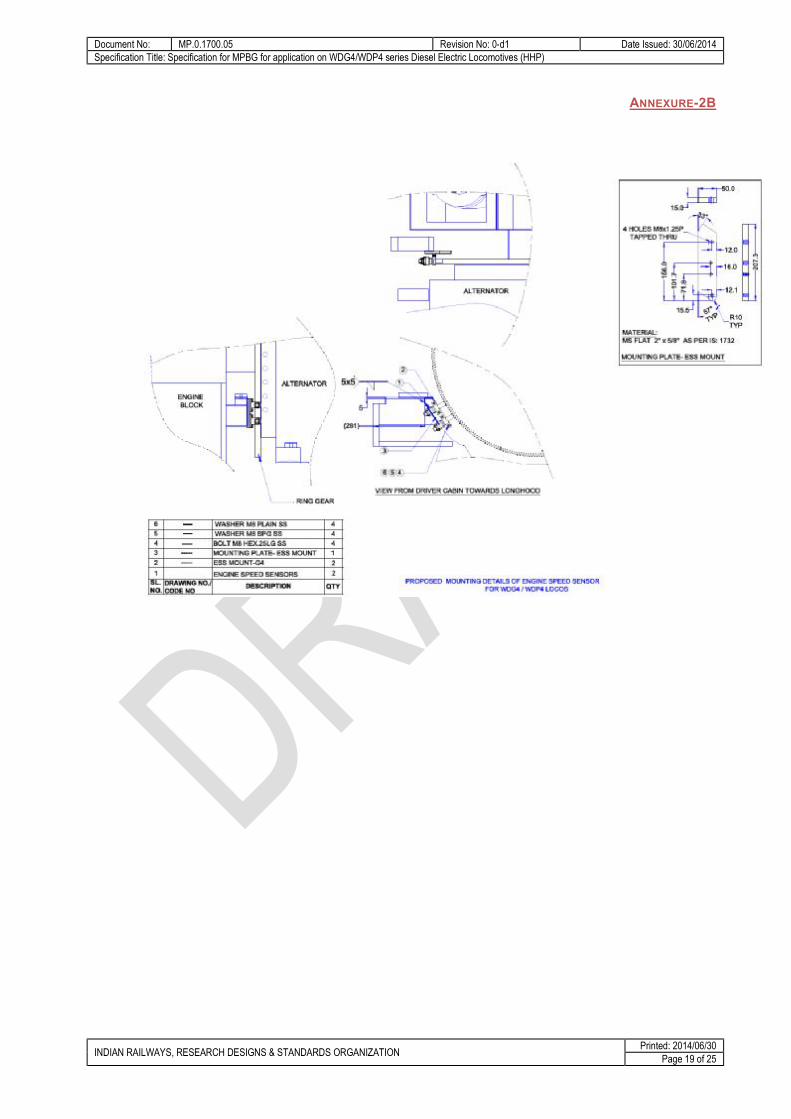
12.4 Engine Speed Sensors Two Engine Speed sensors shall be supplied along with the MPBG for sensing the engine RPM. If one Engine speed sensor fails then the system shall be change over to another healthy Engine speed sensor. Mounting connectors on both the ESS shall be same. Allied or Amphenol make Connectors viz. MS 3102R 12SP-10P. Connection of cable is detailed at Annexure-1. Use of equivalent connectors requires specific permission from RDSO. Speed Sensor to be located near the Ring Gear. L - Bracket for mounting the ESS is enclosed at Annexure 2B.
12.5 Numbering Each Control unit, Actuator unit, Pressure sensor box and Engine Speed sensors shall contain a number plate indicating
a. Serial number b. Date of manufacturing c. Name of manufacturer d. Model number.
The major sub assemblies going into each unit should also be numbered and recorded with the supplier for future reference.
13 Applicable drawings Annexure 1 : Details of cables Annexure 2 : Governor Housing (Part no. 8163123)

Document No: MP.0.1700.05 Revision No: 0-d1 Date Issued: 30/06/2014 Specification Title: Specification for MPBG for application on WDG4/WDP4 series Diesel Electric Locomotives (HHP)
INDIAN RAILWAYS, RESEARCH DESIGNS & STANDARDS ORGANIZATION Printed: 2014/06/30 Page 11 of 25
Annexure 2A : Governor Control Linkage Annexure 2B : Proposed Mounting Details of Engine Speed Sensor Annexure 3 : Methodology for Inspection and testing of MPBG Annexure 4 : Infrastructure Requirements for MPBG Manufacturers Annexure 5 : List of Display Messages in Control unit of MPBG
14 Referred standards The following standards are referred by this specification. It is requested to kindly ensure operational understanding of all the referred standards.
• IEC 60571 • IEC 60812 • IEC 60529 • IEC 62262 • IS 2500 • EDPS 179
15 Maintenance and diagnostic aid The equipment manufacturer shall provide options for maintenance and diagnostic aid for the use by the users and maintainers.
16 Documents required from supplier The manufacturer shall supply the following documents with the equipment. All documents shall be provided in both hard copies and soft copies (PDF)
a. Product catalogue and standard data sheet of offered system
b. Outline and general arrangement drawings
c. Schematic circuit, functional description and protection scheme
d. Schedule of supply, listing all equipment with part numbers
e. Operating instruction and trouble shooting hand book
f. Maintenance manual with full description of maintenance and repair procedures
g. maintenance schedules required along with list of components which are required to be replaced in those schedules
h. List of maintenance spares required for normal maintenance and emergency repairs
i. A copy of detailed bill of materials
j. Recommended list of spares with cost for 3 years maintenance after warranty
k. Test protocol with procedure of testing
l. Details of technical support and training offered
m. Detailed calibration procedure
17 Warranty The manufacturer shall provide warranty as per IRS terms and conditions.
18 Training The supplier shall train adequate number of IR personnel in operation and maintenance of the offered MPBG. Adequate documentation shall be provided. Personnel of Indian Railways shall be nominated to attend. The equipment manufacturers shall arrange training for operations and maintenance of the equipment, as an integral part of the equipment supply.

Document No: MP.0.1700.05 Revision No: 0-d1 Date Issued: 30/06/2014 Specification Title: Specification for MPBG for application on WDG4/WDP4 series Diesel Electric Locomotives (HHP)
INDIAN RAILWAYS, RESEARCH DESIGNS & STANDARDS ORGANIZATION Printed: 2014/06/30 Page 12 of 25
19 Tests & Verification The equipment shall be tested for functional capability, ability to withstand environmental conditions and for reliable performance under field conditions.
20 Sampling plan Sampling shall be done as per IS2500 wherever not specified but required. Sampling shall be done as per the requirements wherever specified in this document. If the specific contract includes specific clause for sampling, the same shall be applicable.
21 Types of tests The equipment shall be subjected to the following types of test during different stages of design approval. Prove out, field trials and testing of the offered MPBG - Testing including prove out & validation shall be in accordance with the referred spec. SN Category of Test Remarks 1. Type tests
(Prototype) These tests shall be done on a sampled lot of prototypes as per IEC 60571. Such tests are required only on initial approval, change of design and change of manufacturing processes. These tests shall be done as pre-requisite for design approval.
2. Field trials These trials shall be conducted for establishing equipment reliability under field conditions. A minimum sample size shall be installed to work under field conditions and performance monitored for a specified time. These shall be conducted after type tests.
3. Routine tests Tests are required to verify the functional working of the system. These may require simulated inputs for testing the operations under full range of inputs. These tests shall be done by the manufacturer during manufacturing and records maintained for inspection.
4. Acceptance tests These tests shall be done on all or sample of lot for bulk supply. Sampling shall be done as per IS2500. These tests shall normally consist of routine tests and additionally those specified in the specific contract.
21.1 Type test and field trials: The prototypes of the equipment shall be subjected to type tests and field trials prior to approval as per the Annexure 3. Prove-out and validation - One MPBG shall be subjected to durability and performance test on suppliers test bed as per the referred standards in presence of IR personnel.
Note: RDSO shall be apprised and approval taken for testing of the equipment at any specific testing agency prior to the tests.
21.2 Field trial At least one loco set of equipment (or as decided by IR) shall be subjected to field trials for 12 months before clearance is given for bulk supply. During this period, the performance of the equipment shall be closely monitored and evaluated by RDSO. These trials are intended to prove
• Reliability under rigorous environmental and operating conditions
• Advantages for locomotive operation and maintenance
• Maintainability of the equipment.
If modifications found necessary as a result of the tests, the supplier at his own cost shall carry out trials after the relevant modifications have been approved by RDSO.
21.3 Makers test certificate for outsourced item
Document No: MP.0.1700.05 Revision No: 0-d1 Date Issued: 30/06/2014 Specification Title: Specification for MPBG for application on WDG4/WDP4 series Diesel Electric Locomotives (HHP)
INDIAN RAILWAYS, RESEARCH DESIGNS & STANDARDS ORGANIZATION Printed: 2014/06/30 Page 13 of 25
All items that are outsourced by the equipment manufacturer shall be indicated so. The type and extent of control that has been exercised shall be provided with proper documentation. The manufacturers (of the outsourced sub-assembly) test certificates shall be provided.
22 Painting, labeling and marking The equipment shall be appropriately painted for operational use, aesthetics and protection. The parts, connector ports, mounting points etc. shall be clearly marked in a manner that these are easily readable and remain legible over the lifetime of the equipment.
The offered MPBG and all major components and parts shall have proper identification and traceability to facilitate failure analysis and life cycle data.
ID plate Name of Component, Make, Sl. No, Date of Manufacture, Ratings shall be provided on all assemblies/subassemblies.
23 Packaging and delivery/shipment The equipment consists of sensitive and fragile electronic systems. These should be packed with precautions required to prevent damage in transit.
All requirements of IRS conditions for packaging and delivery shall be applicable.
24 IPR disclaimer pin pointing responsibility for violation if any on supplier
24.1 Undertaking by equipment manufacturer All the specifications issued by RDSO shall include a requirement of undertaking to be signed by Vendors on “INFRINGEMENT OF PATENT RIGHTS”. The undertaking can be as under
Indian Railways shall not be responsible for infringement of patent rights arising due to similarity in design, manufacturing process, use of similar components in the design & development of this item and any other factor not mentioned herein which may cause such a dispute. The entire responsibility to settle any such disputes/matters lies with the manufacturer/ supplier.
Details / design/documents given by them are not infringing any IPR and they are responsible in absolute and full measure instead of railways for any such violations. Data, specifications and other IP as generated out of interaction with railways shall not be unilaterally used without the consent of RDSO and right of Railways / RDSO on such IP is acceptable to them.
24.2 Declaration of confidentiality of submitted documents by manufacturers
While submitting a new proposal/design, manufacturer must classify their documents confidentiality declaration, such as
This document and its contents are the property of M/s XYZ (Name of the vendor) or its subsidiaries. This document contains confidential proprietary information. The reproduction, distribution, utilization or the communication of this document or any part thereof, without express authorization is strictly prohibited. Offenders will be held liable for the payment of damages. Indian Railways/RDSO is granted right to use, copy and distribute this document for the use of inspection, operation, maintenance and repair etc.

Document No: MP.0.1700.05 Revision No: 0-d1 Date Issued: 30/06/2014 Specification Title: Specification for MPBG for application on WDG4/WDP4 series Diesel Electric Locomotives (HHP)
INDIAN RAILWAYS, RESEARCH DESIGNS & STANDARDS ORGANIZATION Printed: 2014/06/30 Page 14 of 25
ANNEXURE 1
CABLES:
Details of cables No. of Cores/Length Between Locomotive TB and Control unit of MPBG 14 core/ 7mtrs Between MPBG Control unit and MPBG Pressure Sensor box 10core/18mtrs Between MPBG Control unit and MPBG Actuator unit 6 core/21mtrs Between MPBG Actuator unit and MPBG Pressure sensor box 4 core/8mtrs Between MPBG Control unit to MPBG Engine Speed sensors 1 & 2 6 core/17mtrs 1. INPUT & OUTPUT CABLE BETWEEN MPBG CONTROL UNIT TO LOCO TB NO
43E IN DRIVER CONTROL STAND-02
CONNECTOR TYPE
CONNECTOR PIN NO
LOCOMOTIVE WIRE NUMBER
LENGTH OF CABLE CONNECTOR TYPE
BAYONET CONNECTOR MG 3108F 20-29S
K GVA
7 mtrs (14 core) (Tentative cable length provided. Final cable lengths shall be decided after 01 or 02 installation of the units in the Locomotive)
COPPER LUG WIRE DIA:3.56mm, STUD 5mm To Loco Terminal Board
L GVB M GVC A GVD D STFB F LWSFB B PT3 / BP C N4 / BN J LOSFB S LRV G SPARE-1 H SPARE-2
2. PRESSURE SENSOR CABLE BETWEEN MPBG CONTROL UNIT TO PRESSURE SENSOR BOX
CONNECTOR TYPE LENGTH OF CABLE CONNECTOR TYPE
BAYONET CONNECTOR
MG 3108F-18-1SY
18mtrs (10 core)
(Tentative cable length provided. Final cable lengths shall be decided after 01 or 02 installation of the units in the
BAYONET CONNECTOR
MG 3108F-18-1SY
# # # # # # # # # # # # # # #

Document No: MP.0.1700.05 Revision No: 0-d1 Date Issued: 30/06/2014 Specification Title: Specification for MPBG for application on WDG4/WDP4 series Diesel Electric Locomotives (HHP)
INDIAN RAILWAYS, RESEARCH DESIGNS & STANDARDS ORGANIZATION Printed: 2014/06/30 Page 15 of 25
Locomotive)
3. MOTOR & CLUTCH CABLE, BETWEEN MPBG CONTROL UNIT TO ACTUATOR UNIT
CONNECTOR TYPE LENGTH OF CABLE CONNECTOR TYPE
BAYONET CONNECTOR MG 3108F-18-1SZ
21 mtrs (6 core) (Tentative cable length provided. Final cable lengths shall be decided after 01 or 02 installation of the units in the Locomotive)
BAYONET CONNECTOR MG 3108F-18-1SZ
4. FUEL RACK POSITION SENSOR CABLE, BETWEEN MPBG ACTUATOR UNIT
TO PRESSURE SENSOR BOX
CONNECTOR TYPE LENGTH OF CABLE CONNECTOR TYPE
BAYONET CONNECTOR MG 3108F-18-11SX
8 mtrs (4core) (Tentative cable length provided. Final cable lengths shall be decided after 01 or 02 installation of the units in the Locomotive)
BAYONET CONNECTOR MG 3108F-18-11SX
5. ENGINE SPEED SENSOR CABLE, BETWEEN MPBG CONTROL UNIT TO ENGINE SPEED SENSORS (ESS1 & ESS2)
CONNECTOR TYPE LENGTH OF CABLE CONNECTOR TYPE
BAYONET CONNECTOR MG 3108F-16S-1SW
17 mtrs (6 core) (Tentative cable length provided. Final cable lengths shall be decided after 01 or 02 installation of the units in the Locomotive)
MS Round Connector MS 3108F-12SP-10S
# # # # #
# # # # #
# # # # #
# # # # # # # # # ## # # # #

Document No: MP.0.1700.05 Revision No: 0-d1 Date Issued: 30/06/2014 Specification Title: Specification for MPBG for application on WDG4/WDP4 series Diesel Electric Locomotives (HHP)
INDIAN RAILWAYS, RESEARCH DESIGNS & STANDARDS ORGANIZATION Printed: 2014/06/30 Page 16 of 25
6. SHIELD OR EARTH CABLE, BETWEEN MPBG CONTROL UNIT TO LOCOMOTIVE BODY
LUG TYPE LENGTH OF CABLE LUG TYPE
CRIMP LUG RING TYPE 4-6 SQMM HOLE-6.4MM 2.5 mtrs (1 core – 6 Sq.mm) CRIMP LUG RING TYPE 4-6
SQMM HOLE-6.4MM
# # # #

Document No: MP.0.1700.05 Revision No: 0-d1 Date Issued: 30/06/2014 Specification Title: Specification for MPBG for application on WDG4/WDP4 series Diesel Electric Locomotives (HHP)
INDIAN RAILWAYS, RESEARCH DESIGNS & STANDARDS ORGANIZATION Printed: 2014/06/30 Page 17 of 25
ANNEXURE-2
Governor Housing (Part no. 8163123)

Document No: MP.0.1700.05 Revision No: 0-d1 Date Issued: 30/06/2014 Specification Title: Specification for MPBG for application on WDG4/WDP4 series Diesel Electric Locomotives (HHP)
INDIAN RAILWAYS, RESEARCH DESIGNS & STANDARDS ORGANIZATION Printed: 2014/06/30 Page 18 of 25
ANNEXURE-2A
Document No: MP.0.1700.05 Revision No: 0-d1 Date Issued: 30/06/2014 Specification Title: Specification for MPBG for application on WDG4/WDP4 series Diesel Electric Locomotives (HHP)
INDIAN RAILWAYS, RESEARCH DESIGNS & STANDARDS ORGANIZATION Printed: 2014/06/30 Page 19 of 25
ANNEXURE-2B

Document No: MP.0.1700.05 Revision No: 0-d1 Date Issued: 30/06/2014 Specification Title: Specification for MPBG for application on WDG4/WDP4 series Diesel Electric Locomotives (HHP)
INDIAN RAILWAYS, RESEARCH DESIGNS & STANDARDS ORGANIZATION Printed: 2014/06/30 Page 20 of 25
ANNEXURE 3 METHODOLOGY FOR INSPECTION AND TESTING OF MPBG Inspection and testing of the equipment to be supplied by the supplier will be carried out in the following stages. The supplier will provide without any extra charge, the material equipment, tools and any other assistance which the purchaser or his nominee may consider necessary for any test and examination which he or his nominee shall require to conduct at the supplier’s premises and will pay all costs attendant to them. Type tests: The equipment (prototypes) shall be subjected to the following tests:
The environmental, EMI/EMC/RFI tests as per IEC 60571 shall be conducted at any reputed agency having required facilities to do so.
Testing for IP / IK rating of the equipment, shall be conducted at any reputed testing agency having required facilities to do so.
The functional tests for compliance to requirements of this document shall be witnessed by RDSO.
These tests will be carried out on the first prototype submitted for approval. These tests may also be conducted at the following stages at the discretion of RDSO:
i. On the first unit to be supplied under regular production. ii. If there is any change in the design or source of supply of any component/subassembly, on the first
unit made of the changed design or the new source The following tests will constitute the type test: • Environmental tests and other tests compliance: One prototype unit of the MPBG will be subjected to the environmental tests as detailed in IEC 60571 for railway electronics. • Functional test: These tests will be carried out under simulated conditions at supplier’s premises to establish that the governor is functioning as per the specification. On satisfactory completion of environmental and functional tests, the prototypes will be subjected to performance tests. Functional tests would also be carried out before and after the environmental tests to check any damage or change in behaviour. • Performance test: Performance test of first two prototypes will be carried out on 16 cylinder 710 series diesel engine fitted on HHP type/DLW locomotives of Indian Railways. In addition to validating compliance to this spec. performance tests will consist of the following:
i. The maximum instantaneous variation in engine speed expressed as percentage of rated speed, after sudden variation of load from the rated value to zero must not exceed 10% of the rated speed.
ii. Possible faults will be created to test the fail safe features of the governor (to be listed out by the supplier and got approved by RDSO).
On satisfactory completion of the performance tests, the MPBG will be cleared by the inspecting authority for field trials. • Routine tests:

Document No: MP.0.1700.05 Revision No: 0-d1 Date Issued: 30/06/2014 Specification Title: Specification for MPBG for application on WDG4/WDP4 series Diesel Electric Locomotives (HHP)
INDIAN RAILWAYS, RESEARCH DESIGNS & STANDARDS ORGANIZATION Printed: 2014/06/30 Page 21 of 25
The MPBG cleared for regular use will be subjected to routine tests. These tests will consist of functional tests and shall be conducted in the presence of the inspecting authority at supplier’s premises.
• Acceptance test The acceptance test shall include:
a. Verification of equipment conformance by checking of type test reports, manufacturers certificates for outsourced components.
b. Functional tests of the equipment.
Document No: MP.0.1700.05 Revision No: 0-d1 Date Issued: 30/06/2014 Specification Title: Specification for MPBG for application on WDG4/WDP4 series Diesel Electric Locomotives (HHP)
INDIAN RAILWAYS, RESEARCH DESIGNS & STANDARDS ORGANIZATION Printed: 2014/06/30 Page 22 of 25
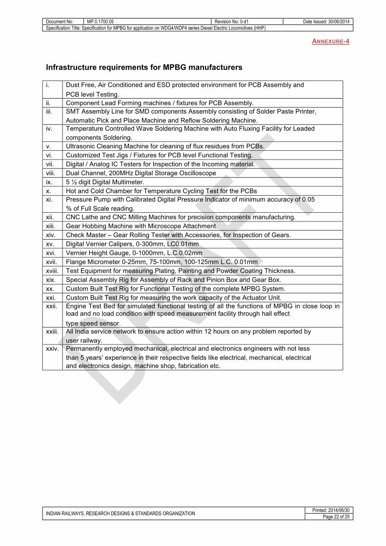
ANNEXURE-4
Infrastructure requirements for MPBG manufacturers i. Dust Free, Air Conditioned and ESD protected environment for PCB Assembly and PCB level Testing. ii. Component Lead Forming machines / fixtures for PCB Assembly. iii. SMT Assembly Line for SMD components Assembly consisting of Solder Paste Printer, Automatic Pick and Place Machine and Reflow Soldering Machine. iv. Temperature Controlled Wave Soldering Machine with Auto Fluxing Facility for Leaded components Soldering. v. Ultrasonic Cleaning Machine for cleaning of flux residues from PCBs. vi. Customized Test Jigs / Fixtures for PCB level Functional Testing. vii. Digital / Analog IC Testers for Inspection of the Incoming material. viii. Dual Channel, 200MHz Digital Storage Oscilloscope ix. 5 ½ digit Digital Multimeter. x. Hot and Cold Chamber for Temperature Cycling Test for the PCBs xi. Pressure Pump with Calibrated Digital Pressure Indicator of minimum accuracy of 0.05 % of Full Scale reading. xii. CNC Lathe and CNC Milling Machines for precision components manufacturing. xiii. Gear Hobbing Machine with Microscope Attachment. xiv. Check Master – Gear Rolling Tester with Accessories, for Inspection of Gears. xv. Digital Vernier Calipers, 0-300mm, LC0.01mm xvi. Vernier Height Gauge, 0-1000mm, L.C.0.02mm xvii. Flange Micrometer 0-25mm, 75-100mm, 100-125mm L.C. 0.01mm xviii. Test Equipment for measuring Plating, Painting and Powder Coating Thickness. xix. Special Assembly Rig for Assembly of Rack and Pinion Box and Gear Box. xx. Custom Built Test Rig for Functional Testing of the complete MPBG System. xxi. Custom Built Test Rig for measuring the work capacity of the Actuator Unit. xxii. Engine Test Bed for simulated functional testing of all the functions of MPBG in close loop in
load and no load condition with speed measurement facility through hall effect type speed sensor. xxiii. All India service network to ensure action within 12 hours on any problem reported by user railway. xxiv. Permanently employed mechanical, electrical and electronics engineers with not less than 5 years’ experience in their respective fields like electrical, mechanical, electrical and electronics design, machine shop, fabrication etc.
Document No: MP.0.1700.05 Revision No: 0-d1 Date Issued: 30/06/2014 Specification Title: Specification for MPBG for application on WDG4/WDP4 series Diesel Electric Locomotives (HHP)
INDIAN RAILWAYS, RESEARCH DESIGNS & STANDARDS ORGANIZATION Printed: 2014/06/30 Page 23 of 25
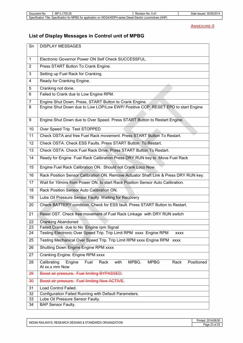
ANNEXURE-5
List of Display Messages in Control unit of MPBG
Sn DISPLAY MESSAGES
1 Electronic Governor Power ON Self Check SUCCESSFUL.
2 Press START Button To Crank Engine.
3 Setting up Fuel Rack for Cranking.
4 Ready for Cranking Engine.
5 Cranking not done. 6 Failed to Crank due to Low Engine RPM.
7 Engine Shut Down. Press, START Button to Crank Engine. 8 Engine Shut Down due to Low LOP/Low EWP/ Positive CCP. RESET EPD to start Engine
9 Engine Shut Down due to Over Speed. Press START Button to Restart Engine.
10 Over Speed Trip Test STOPPED 11 Check OSTA and free Fuel Rack movement. Press START Button To Restart.
12 Check OSTA. Check ESS Faults. Press START Button To Restart.
13 Check OSTA. Check Fuel Rack Drive. Press START Button To Restart.
14 Ready for Engine Fuel Rack Calibration Press DRY RUN key to Move Fuel Rack
15 Engine Fuel Rack Calibration ON. Should not Crank Loco Now.
16 Rack Position Sensor Calibration ON. Remove Actuator Shaft Link & Press DRY RUN key.
17 Wait for 10mins from Power ON, to start Rack Position Sensor Auto Calibration.
18 Rack Position Sensor Auto Calibration ON.
19 Lube Oil Pressure Sensor Faulty. Waiting for Recovery
20 Check BATTERY condition. Check for ESS fault. Press START Button to Restart.
21 Reset OST. Check free movement of Fuel Rack Linkage with DRY RUN switch
22 Cranking Abandoned 23 Failed Crank due to No Engine rpm Signal 24 Testing Electronic Over Speed Trip. Trip Limit RPM xxxx Engine RPM xxxx
25 Testing Mechanical Over Speed Trip. Trip Limit RPM xxxx Engine RPM xxxx
26 Shutting Down Engine Engine RPM xxxx
27 Cranking Engine. Engine RPM xxxx
28 Calibrating Engine Fuel Rack with MPBG. MPBG Rack Positioned At xx.x mm Now
29 Boost air pressure. Fuel limiting BYPASSED.
30 Boost air pressure. Fuel limiting Now ACTIVE.
31 Load Control Failed. 32 Configuration Failed Running with Default Parameters. 33 Lube Oil Pressure Sensor Faulty. 34 BAP Sensor Faulty.

Document No: MP.0.1700.05 Revision No: 0-d1 Date Issued: 30/06/2014 Specification Title: Specification for MPBG for application on WDG4/WDP4 series Diesel Electric Locomotives (HHP)
INDIAN RAILWAYS, RESEARCH DESIGNS & STANDARDS ORGANIZATION Printed: 2014/06/30 Page 24 of 25
Sn DISPLAY MESSAGES
35 FOP Sensor Faulty. 36 Fuel Rack Drive Motor Over Current. Check OSTA
37 OSTA Tripped or Fuel Rack Drive Failed. STOP Cranking Engine
38 Fuel Rack Position Sensor recovered from Fault.
39 LOP Sensor recovered from Fault.
40 BAP Sensor recovered from Fault . 41 FOP Sensor recovered from Fault. 42 Load Control Fault Recovered 43 Unable to Calibrate Rack Position Sensor
44 Difference between two sensor speeds Is high
45 ESS1 speed sensor Misbehaving 46 ESS2 speed sensor Misbehaving 47 ESS1 speed sensor Wire open fault 48 ESS2 speed sensor Wire open fault 49 ESS1 showing high RPM at zero speed 50 ESS2 showing high RPM at zero speed 51 ESS1 Sensor Recovered from Faults
52 ESS2 Sensor Recovered from Faults
53 TL13 High or Low Fault 54 TL13 High or Low Fault Recovered 55 Fuel Pump Breaker Tripped or Low FOP
56 OSTA Tripped or Fuel Rack Drive obstructed Or Motor Failed. Shutting Down Engine
57 Low LOP or Low EWP or Positive Crank Case Pressure. Shutting Down Engine
58 OSTA Tripped or ESS Failed Shutting Down Engine
59 Over Speed. Shutting Down Engine. 60 Electronic Over Speed Trip. Test Failed 61 Mechanical Over Speed Trip Test Failed 62 Switch OFF power Wait for 5 Minutes. Switch ON power To Restart Engine.
63 Lube Oil Pr. Sensor Failed. Switch OFF Power & repair Sensor To restart Engine
64 Fuel Rack Position Sensor Faulty. 65 BATTERY weak or ESS faulty. STOP Cranking. 66 OST TRIPPED. Reset OST. Move Fuel Rack Linkages manually To free them.
67 PEN DRIVE CONNECTED 68 FILES DOWNLOAD COMPLETED 69 PEN DRIVE NOT SUPPORTED 70 DEVICE WRITE PROTECTED 71 LESS SPACE IN PEN DRIVE 72 Electronic O.S.T. Test Successful. Trip Limit RPM xxxx Tripped at RPM xxxx
73 Mechanical O.S.T. Test Successful. Trip Limit RPM xxxx Tripped at RPM xxxx
74 Mechanical OST Level To be increased Trip Limit RPM xxxx Tripped at RPM xxxx
75 Rack Position Sensor Calibration Success. Max. Error xx.xx mm AT xx.xx mm
76 Rack Position Sensor Calibration Failed Max. Error . Deg AT . Deg 77 Notch Fault

Document No: MP.0.1700.05 Revision No: 0-d1 Date Issued: 30/06/2014 Specification Title: Specification for MPBG for application on WDG4/WDP4 series Diesel Electric Locomotives (HHP)
INDIAN RAILWAYS, RESEARCH DESIGNS & STANDARDS ORGANIZATION Printed: 2014/06/30 Page 25 of 25
Sn DISPLAY MESSAGES
78 BAP Limit 79 HP Limit 80 Rack Position Error 81 BAP Load Control


![edkuksa dks vkinkjks/kh cukus ds 4326 ij vk/kkfjr gSaAbsdma.org/images/publication/Masonry Guide.pdf · bu Hkouksa dks vkinkjks/kh cukus ds bl ekxZnf’kZdk ds rjhds] Hkkjrh; ekud](https://static.fdocuments.in/doc/165x107/5e1d518fc0309d37a85c90e3/edkuksa-dks-vkinkjkskh-cukus-ds-4326-ij-vkkkfjr-guidepdf-bu-hkouksa-dks-vkinkjkskh.jpg)