Eisenhower/Johnson Memorial Tunnel · Eisenhower/Johnson Memorial Tunnel ... F 303.377.6163 ... The...
68
Eisenhower/Johnson Memorial Tunnel 2400V Medium Voltage Switchgear Conceptual Design Evaluation Preliminary Report September 2009 Prepared by: Hatch Mott MacDonald Inc 1700 Broadway, Suit 660 Denver 80290 T 303.663.8839 F 303.377.6163 Prepared for: Colorado Department of Transportation
Transcript of Eisenhower/Johnson Memorial Tunnel · Eisenhower/Johnson Memorial Tunnel ... F 303.377.6163 ... The...

Eisenhower/Johnson Memorial Tunnel 2400V Medium Voltage Switchgear Conceptual Design Evaluation
Preliminary Report
September 2009 Prepared by: Hatch Mott MacDonald Inc
1700 Broadway, Suit 660 Denver 80290 T 303.663.8839 F 303.377.6163
Prepared for: Colorado Department of Transportation


Preliminary Report
i
List of Contents Page
Abbreviations iv
Glossary v
Executive Summary S-1
Chapters and Appendices
1 Introduction 1 1.1 Background 1 1.2 Scope of Work 2
2 Existing Conditions 3 2.1 Design Standards 4 2.2 Existing Tunnel Ventilation Restrictions And Operations 4
3 MCC Supplier Liaison 5 3.1 General Electric 6 3.2 Square-D 6 3.3 Powell 7 3.4 ABB 7 3.5 Sole Sourcing Report 8
4 Cost Review 8 4.1 Comparison of 2006 Costs – Option 1 9 4.2 Comparison of Costs – Option 2 9 4.3 Comparison of Costs – Option 3 10 4.4 Comparison of Costs – Option 4 10 4.5 Equipment Costs 10
5 24.9 kV Switchgear Review 11
6 Options Selection Review 12 6.1 Layout Configuration 12 6.2 Review Constructability of Options 13
6.2.1 Option 1 – Changeover Sequencing 13

Preliminary Report
ii
6.2.2 Option 1 – Advantages and Disadvantages 14 6.2.3 Option 2 – Changeover Sequencing 15 6.2.4 Option 2 – Advantages and Disadvantages 16 6.2.5 Option 3 – Changeover Sequencing 17 6.2.6 Option 3 – Advantages and Disadvantages 17 6.2.7 Option 4 – Changeover Sequencing 18 6.2.8 Option 4 – Advantages and Disadvantages 19
6.3 Quantitative Review of Options 20
7 Design Development 22
8 Conclusions and Recommendations 24
9 References 25
Appendix A DRAWINGS A-1
Appendix B COST REVIEW B-2
Appendix C WHITE PAPER – SOLE SOURCING REVIEW OF MCC SWITCHGHEAR C-3

Preliminary Report
iii
Abbreviations ABB ASEA Brown Boveri
CDOT Colorado Department of Transportation
CECON Completely Enclosed for Continuous Operation
CFD Computer Fluid Dynamics
CSI Construction Specification Institute
EE East Extract
ES East Supply
GE General Electric
HMM Hatch Mott MacDonald
HP Horse Power
kV Kilovolt
kcmil 1000 circular mils
MCC Motor Control Center
PB Parsons Brinkerhoff
V Volts
VFD Variable Frequency Drive
WE West Extract
WS West Supply

Preliminary Report
S-1
Executive Summary
The purpose of this project was to prepare a set of design documents to facilitate the replacement of 2400V motor control center (MCC) equipment at the Eisenhower Johnson Memorial Tunnel (EJMT) in the State of Colorado (CDOT). This study has been commissioned by Parsons Consulting to evaluate CDOT’s options for the replacement of the existing 2400V MCC, identify and recommend the best option for the replacement program.
This section provides a summary of the main chapters of the full report. At the end of each paragraph, the number shown in parentheses references the section of this report where additional details can be found.
Existing As-Built drawings have been evaluated as well as Electrical Inspection Report, Fire Emergency Ventilation Study and Power Study to ensure that the options considered take into account the findings of these reports (1.1).
HMM visited the EJMT on December 2008 and evaluated the constraints associated with implementing Option 1 (New MCC Line-up with Temporary MCC During Construction). As a result of the site visit, HMM prepared a presentation outlining the proposed scope of this evaluation to review Option 1 against Option 2 (Retrofit Partial Replacement), Option 3 (New Sequenced Modular Replacement) and option 4 (Full Replacement). (1.2).
HMM identified the tunnel ventilation modes of operation and operational restrictions, including which fans are used for a given ventilation mode and which fans and line-ups can be taken out of service at any one time during the replacement period (2.2 and 2.3).
We have performed an extensive MCC supplier liaison and contacted GE, Square D, Powell, ABB and Eaton to obtain equipment limitations, space requirements, budgetary costs and compatibility with existing switchgear (3.0 and Table 4.2).
As a prerequisite to this report, HMM prepared a White Paper to evaluate whether the provision of the MCC retrofit and MCC cubicle replacement Options 2 and 3 required sole sourcing by the original manufacturer, GE. The conclusions is that sole sourcing by GE for Options 2 and 3 is not necessary since Square D can provide these options. The White Paper is summarized in this report and a copy of the White Paper has also been included in the Appendices for completeness (3.5).
The cost review of the Options that has been preformed concludes that the lowest cost is Option 3 (New Sequenced Modular Replacement) at $2,712,019. Option 1 (New MCC Line-up with Temporary MCC During Construction) is budgeted at $4,576,400. Option 2 (Partial Replacement) is budgeted at $2,827,610. Option 4 (Full Replacement) is budgeted at $3,132,665(4.0). Further, Option 1 budget at 2006 rates of $3,000,000 have been revised to 2009 rates at a cost of at $4,576,400 (4.0).

Preliminary Report
S-2
HMM has reviewed the 24.9 kV switchgear location and performed a space proofing exercise to determine if replacing the 24.9 kV switchboard will generate additional space to facilitate the MCC or other switchgear changeover. The review concludes that substantial space savings can be made in the order of 33 percent. Two major challenges need to be addressed to achieve these saving, firstly development of a staged changeover program that will minimize the disruption to tunnel operations and secondly the need to route high voltage cables to the new switchboard location (5.0).
In order to evaluate the constructability of the four options, HMM has prepared a set of changeover sequencing drawings and equipment layout drawings that show the principals and main steps required to implement the proposed replacement option and the space constraints (6.2).
The constructability, safety, operational capability, maintainability, space planning, cost and impact to schedule have been reviewed and summarized in a qualitative evaluation (Table 6.1). Each design and construction criteria has been rated against each of the four options and given a rating between one (low score) and four (high score), where four is preferred. Our quantitative evaluation concludes that Option 3 (New Sequenced modular replacement) is the highest score with a rating of 48/52, this is therefore the preferred option. (6.3).
It is our recommendation that Option 3 is taken forward to the next detailed design stage of the MCC replacement program.

Preliminary Report
Page 1 of 25
1 Introduction
As part of the Hatch Mott MacDonald (HMM) on-call contract with Parsons Consulting, HMM has been appointed to perform a conceptual design evaluation for the replacement of the four 2.4 kV motor control centers (MCC) that serve the supply and exhaust ventilation fans in the Eisenhower/Johnson Memorial Tunnel eastbound bore.
Administrated by Colorado Department of Transportation (CDOT), the Eisenhower/Johnson Memorial Tunnel is located on Route 70, approximately 60 miles west of Denver, Colorado and is a main artery for commercial transport as well as for public travel. The tunnel was constructed in two phases: the westbound bore or North Tunnel, completed in 1973 and the eastbound bore or South Tunnel, completed in 1979 ; the South Tunnel is the subject of this evaluation. The tunnel is located in Colorado Rocky Mountains at an elevation over 11,000 feet above sea level.
HMM has teamed with Careba Mott MacDonald and visited the site in December 2008 to assess the possibilities of replacing the MCCs located in electrical equipment rooms at both ends of the South Tunnel. One option to consider the replacement of existing 2400V equipment with 480V equipment has been rejected by CDOT in the initial discussions. At the end of the visit the team presented Parsons Consulting and CDOT four possible replacement options together with advantages and disadvantages, space constraints and issues that needed to be resolved by discussions with the manufacturers.
1.1 Background
Parsons Brinckerhoff Quade and Douglas, Inc1. performed an equipment inspection evaluation of all the Eisenhower/Johnson Memorial Tunnel electrical systems and identified the equipment that needs to be replaced, budget costs and the appropriate time for replacement. The report proposed to replace the existing South Tunnel MCC line-ups with four new line-ups, using two additional line-ups to achieve the temporary changeover sequence. This forms the base option and is referred to in this report as Option 1.
HMM has reviewed existing As-Built drawings supplied form CDOT identifying the existing As-Built condition of the 2400V MCC line-ups, including layout drawings, One Line Diagrams and detailed control schematics. As-Built drawings have not been kept up to date as additional equipment has been added to the facility over the years.
The replacement of existing 480V motor control switchgear that feeds the Eisenhower North Tunnel has recently been updated. HMM has used 480V As-Built equipment location plans as the basis of their equipment location drawings.
HMM has reviewed the Electrical Inspection Report Vol I and II by Parsons Brinkerhoff Quade & Douglas, Inc, June 20061. The purpose of this report was to perform a physical inspection of the electrical system including the 2400V motor control centers. The study also performed reliability analysis and budget cost. HMM has used this report to gain a good understanding of the condition of the electrical MCC line-ups and the configuration of the electrical network. The budget costs from this report have been reviewed against 2009 rates as identified in the Cost review section of this report.

Preliminary Report
Page 2 of 25
HMM has also reviewed the Fire Emergency Ventilation Study by Sverdrup, May 24, 20042. This report was prepared to evaluate the effects of the tunnel ventilation system in the event of a single tunnel closure. Computer Fluid Dynamics (CFD) simulations were performed as part of the study to identify the operation of the ventilation fans in the event of a fire in each of the five ventilation zones. HMM has used these modes to evaluate the MCC replacement option fan outages.
The power study performed by PB Americas, May 20073 has also been reviewed by HMM. The purpose of this report was to evaluate the electrical power system operation and confirm that the system operates within acceptable limits, regarding volt drop, equipment rating, short circuit, protection settings and protection discrimination. HMM has not needed to refer to specific data from this report for the evaluating the MCC replacement options.
1.2 Scope of Work
Using our expert knowledge in tunnel fire life safety, operations and electrical systems, Hatch Mott MacDonald have been tasked with providing a feasibility report to review and evaluate the Parsons Brinckerhoff Quade and Douglas replacement option against the four options considered during the December 2008 site visit.
The scope covers the existing 2400V MCCs feeding the South Tunnel ventilation fans in the Johnson Memorial Tunnel. This report will evaluate the options based on constructability, safety, operational capability, maintainability, space planning, cost and impact to future construction schedule.
The MCC replacement alternatives under review are:
• Option 1- New Panels, With Temporary MCC during Construction. As identified by the Electrical Inspection Report (PB, July 2006)1, this option would include the installation of temporary MCCs necessary to maintain tunnel ventilation during the changeover period. The existing MCCs functionality will be transferred to the temporary line-ups, thus freeing them up for permanent replacement. The permanent MCCs will then be installed in the footprints of the removed existing line-ups for permanent usage. Upon completion, the temporary, redundant MCC line-ups would be removed and used in the remote end tunnel ventilation equipment room to again perform the swap over replacement;
• Option 1A - New Panels, With Temporary MCC during Construction. This options was proposed by Square D during their site visit. Square-D preferred supporting a modified Option 1, in this scenario a new MCC utilized for temporary operation at one end (say east) of the tunnel would later be installed permanently at the west end. For this scenario, once the new east MCC line up is commissioned on a temporary basis, the existing east MCC line up could be removed and transferred to the west on a temporary basis. A new final MCC line up could then be installed in the east. Once the west temporary MCC lineup is commissioned, the existing west lineup could be removed allowing a new east lineup, transferred from the east temporary, to be installed in the west as a final location. This would require the purchase of only four new MCCs without the additional expense of temporary fifth and sixth MCCs. This modified Option 1 (Option 1A) would require the temporary commissioning followed by decommissioning, relocation and then the permanent commissioning of one new MCC, and the careful decommissioning of one MCC that would be relocated for temporary use. HMM considered this Option during the December 2007 site visit. There are risks associated with moving existing 30 year old equipment from one end to

Preliminary Report
Page 3 of 25
the other and then reconnecting it into service in the same manner that it was removed. HMM perceived that these risks would increase the construction schedule and so this option was not considered further;
• Option 2 - Retrofit Partial Refurbishment. Option 2 involves the retrofit of existing MCC components and the retention of the existing MCC cubicle sheet metal shells and main bus. This alternative would involve the refurbishment of the components located in a single MCC cubicle and would utilize the existing MCC footprint. The existing cubical sheet metal and main bus would remain. The disconnect switch fuses and starter contactor would be replaced with new retrofitted components;
• Option 3 - New Panels Sequenced (modular replacement). This option includes the replacement of existing MCC components, sheet metal shells and main bus in the existing MCC line-up . This alternative would involve the replacement of a single MCC cubicle or module one at a time and utilize the existing MCC footprint. The difference between Option 3 and Option 2 is that the sheet shell and main bus will be replaced in Option 3, and
• Option 4 - Full Refurbishment. Option 4 involves a new MCC line-up that would be located on a new MCC footprint. The new MCC line-up would be commissioned into service and allow existing MCC functionality to be transferred to the new line-up. Upon completion, the existing MCC line-up would be de-commissioned. This alternative requires new MCC locations to be made available in the existing Tunnel Services Buildings and sufficient space to be allocated for maintenance and removal of major electrical equipment.
This report will thoroughly evaluate all options for the replacement of the existing 2400V MCCs and identify and recommend the best option for the replacement program.
2 Existing Conditions
The existing Johnson (South Tunnel) tunnel ventilation system consists of twelve fans, six supply and six exhaust, that are housed in East and West ventilation equipment rooms located at each end of the tunnel.
The South Tunnel ventilation fans are 2400V dual speed motor driven fans that have four operational speeds and are utilized for pollution ventilation and fire smoke control. There are four 2400V MCCs, with one exhaust line-up, 1A and one supply line-up, 1B in each of the two electrical equipment rooms. The MCCs have two speed, two winding starters for the 24 total motors that support the 12 total fans. The MCCs were manufactured by General Electric (GE) and are Limitamp type, rated 5kV, 1000A, 200MVA. They are over 30 years old and are approaching the end of their determined useful life cycle.
The East electrical equipment houses three supply fan and three exhaust fan MCCs (each bank of three fans will be referred to as a single MCC line-up). This arrangement is replicated at the West electrical room. Each fan is driven by two dual-speed motors, with motor one rated 600/100 HP and the second motor rated 200/25 HP, each fan starter ensemble will be referred to as a single MCC cubicle. The gear drive units and the CECON (Completely Enclosed for Continuous Operation) clutch are configured for pollution control to start the 100 HP motor first to overcome fan inertia, before reverting back down to the 25 HP motor operations.

Preliminary Report
Page 4 of 25
The larger motors are designed to operate during a fire to provide smoke control. Under normal conditions, full speed, 600HP fan operation is not required. The smaller motors are designed to exhaust vehicle emissions smoke and also to start the extraction of smoke in the event of a fire.
The existing 2400V MCC line-up have been modified to include additional feeder circuits that provide feeds to transformers and distribution circuits in the tunnels cross cut electrical spaces. These circuits supply 277V tunnel lighting circuits. Part of the tunnel lighting is fed from the North Tunnel 480V system and part from the South Tunnel 2400V.
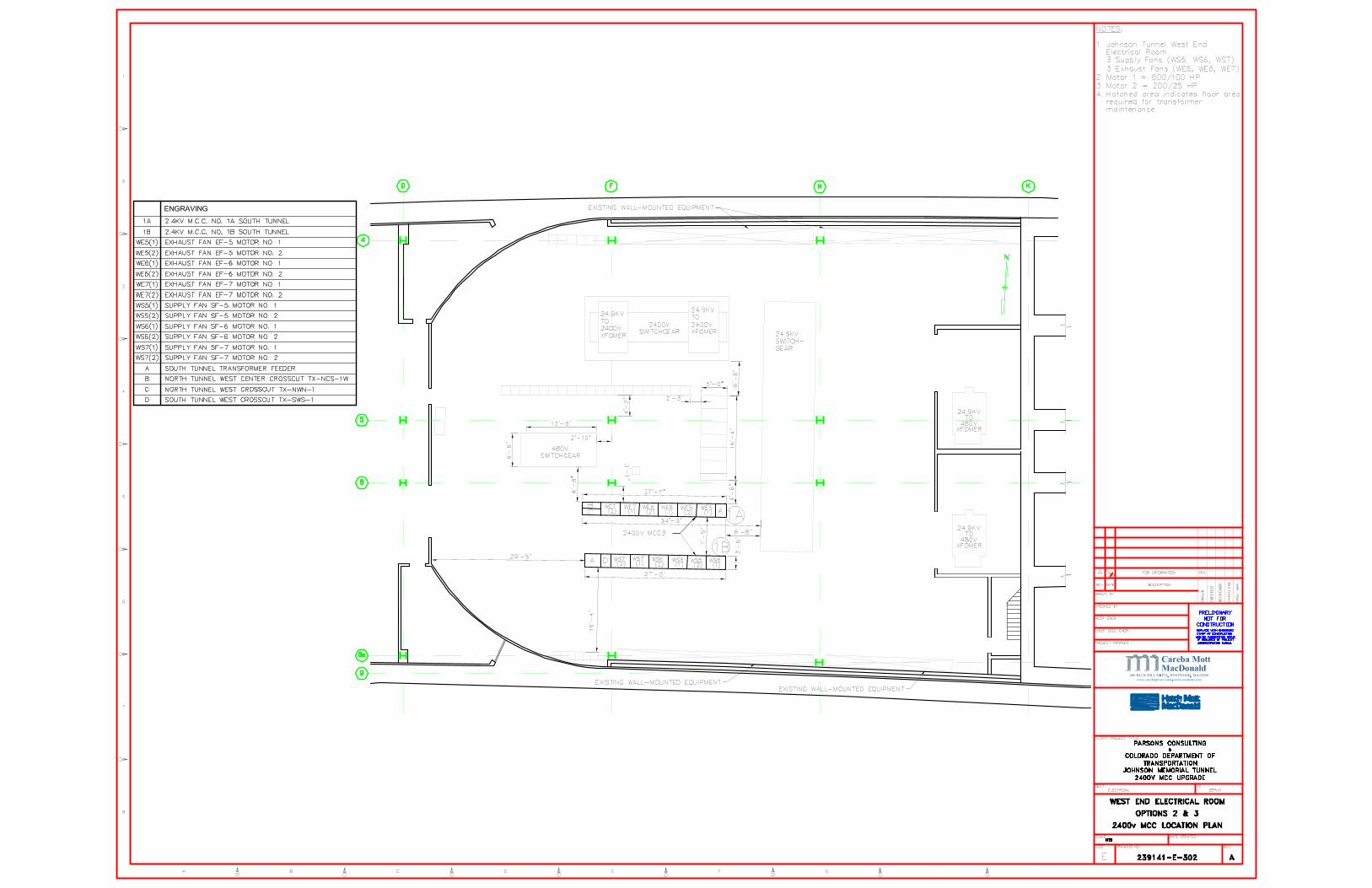
Refer to drawings 239141-E-303 East End Option 2 and 3 2400V MCC Location Plan and 239141-E-302 West End Option 2 and 3 2400V MCC Location Plan for layout of the existing MCC line-ups at the East and West electrical equipment rooms.
2.1 Design Standards
The following standards are applicable:
• Institute of Electrical and Electronic Engineers (IEEE);
• National Electrical Manufacturers Association (NEMA);
• National Electric Code (NEC) (NFPA 70);
• American National Standards Institute (ANSI);
• International Electrotechnical Commission (IEC);
• Underwriters' Laboratories, Inc. (UL);
• American Society for Testing and Materials (ASTM);
• National Electrical Safety Code (NESC);
• Occupational Safety and Health Administration (OSHA), and
• International Electrical Testing Association (NETA).
2.2 Existing Tunnel Ventilation Restrictions And Operations Tunnel operations must be maintained at all times. Based on the configuration above, one exhaust fan per MCC line-up and one intake fan per MCC line-up only may be out of service for extended periods for one end of the tunnel. The EJMT Tunnel Operations4 have confirmed the following operational restrictions for the existing tunnel ventilation system:
• If one of the three fans in an MCC line-up is out of service, smoke will be controlled by use of the remaining two fans in the line-up;
• Having one fan down per MCC line-up is acceptable (e.g. West Supply 5 and West Exhaust 5);

Preliminary Report
Page 5 of 25
• A complete outage of any one complete MCC line-up should not exceed 10 hours. Only one complete MCC line-up per ventilation building is acceptable, and
• MCCs outages need to be planned to occur during weekdays to minimize the impact on tunnel users during high traffic volume periods.
It is noted that the East end MCC cubicle line-up has a spare cubicle. To achieve compatibility of floor space and cable connections, it is recommended that a spare cubicle will be also added to the new MCC.
By NFPA70, Table 110.26(A)(1), 2400V MCCs require a minimum clearance of 3 feet 6 inches where there are exposed live parts on one side of the working space and grounded parts on the other side, and a minimum clearance of 4 feet where there are exposed live parts of both sides of a working space. Clearances of 4 and 5 feet respectively were used when space proving all possible MCC relocation positions.
3 MCC Supplier Liaison
HMM has contacted multiple electrical equipment manufacturers and service providers to discuss and obtain space requirements, budgetary costs, UL listing and switchgear compatibility against existing site conditions.
The manufacturers contact information is as follows:
GE service Rhea Barnett e-mail [email protected] phone (303)-329-2336
Square D service Mark Zuber e-mail [email protected] phone (303)-330-7859
Powell service Pullen, Mike e-mail [email protected] phone (713)-947-4423
Eaton Chasson Doe e-mail [email protected] phone (774)-235-0216
ABB rep Power Equipment Sales Company (PESCO)
Pete Asselin e-mail [email protected] phone (978)-774-6680
GE and Square D performed a site visit to inspect and evaluate the equipment for the replacement or retrofit options. This was to ensure that options where viable and to determine if sole sourcing of existing GE gear was required.
A summary of the findings from the suppliers liaison is outlined in the following sections.
Preliminary Report
Page 6 of 25
3.1 General Electric
GE visited the EJMT on June 11, 2009, a summary of the meeting was recorded by CDOT5. The results of their visit are summarized below:
1. Availability of spare parts for the existing MCC presents problems as replacement parts are scarce;
2. Existing MCCs are dated 1967; GE’s latest MCCs are four generations past the existing;
3. Existing width (44-inch) is a standard size for this type of equipment;
4. Existing bus very likely to be bolted between sections and not continuous. This would allow Option 3 be to easily implemented;
5. A single fan can be unavailable for a longer period but the client prefers down time for a single MCC bus outage to be ten hours;
6. Option 2 could be accommodated but would likely require GE technicians on site to install the components resulting in increased work cost. In addition, space will need to be made available for local storage of electrical components, work space, tools and equipment;
7. GE can provide a UL listing for the replacement MCCs related to Options 2 and 3;
8. GE was advised of CDOT’s requirement for compliance with the Buy American Act related to the steel cabinets;
9. Programmable Logic Controls (PLC) could accommodate the replacement Options 2 and 3;
10. GE recommends and is ready to support the implementation of Option 3, and
11. GE is able to support Option 1 or 4 if needed.
3.2 Square-D
Square-D visited the EJMT on June 25, 2009. Square-D was provided with the pictures of the inside of the cubicles taken by GE. The findings of their visit are summarized as follows:
1. Square-D confirmed they could support Option 2. They indicated that they have worked with GE Limitamp gear before. They indicated this option was labor intensive and would require multiple outages between 16 and 24 hours;

Preliminary Report
Page 7 of 25
2. Square-D confirmed they could support Option 3 replacement. Due to differences in bus placement and configuration, temporary transition sections may need to be employed. After all sections have been changed to Square-D gear the new line-up would be located in the same footprint. The need to replace all MCC sections would be constrained by retaining the lighting control cabinets. Square-D believes that this can be done in multiple outages of about 8 to 12 hours;
3. Square-D preferred supporting a modified Option 1. In this scenario a new MCC utilized for temporary operation at one end (say east) of the tunnel would later be installed permanently at the west end. For this scenario, once the new east MCC line-up is commissioned on a temporary basis, the existing east MCC line-up could be removed and transferred to the west on a temporary basis. A new final MCC line-up could then be installed in the east. Once the west temporary MCC line-up is commissioned, the existing west line-up could be removed allowing a new east line-up, transferred from the east temporary, to be installed in the west as a final location. This would require the purchase of only four new MCCs without the additional expense of a temporary fifth or sixth MCC. This modified Option 1 (Option 1A) would require the temporary commissioning followed by decommissioning, relocation and then the permanent commissioning of one new MCC, and the careful decommissioning of the existing MCC that would be relocated for temporary use;
4. Square-D requested a copy of the PB Power Study and GE drawings, and
5. Square-D indicated that a UL label could be provided for the retrofitted gear by having an UL inspector evaluate the final assembly. This is most applicable to Option 2.
3.3 Powell
Powell was provided with the GE drawings of the existing MCCs and some photographs, some of which were taken by GE during their site visit. The findings of their evaluation are summarized below:
1. Powell believes that they can support either Option 2 or Option 3, and
2. Powell has not provided definite details as to how they might be able to support at this time.
3.4 ABB
ABB was provided with the GE drawings of the existing MCCs and some photographs, some of which were taken by GE during their site visit. The findings of their evaluation are summarized as follows:
1. HMM has yet to receive a reply from ABB regarding their ability to support either Options 2 or 3.

Preliminary Report
Page 8 of 25
3.5 Sole Sourcing Report
HMM submitted a White Paper on July 9, 2009 for Sole Sourcing of MCC Equipment6. The purpose of this paper was to identify whether the replacement of MCC equipment needs to be sole sourced through the existing MCC manufacturer GE. A summary of the conclusions are included for completeness:
Options 1, 1A and 4 - Options 1, 1A (modified Option 1 recommended by Square-D, see 3.2) and 4 include the installation of completely new MCC line-ups for which a number of manufacturers capable of fulfilling the requirements have been identified. Option 4 does not require sole sourcing since the option involves a new MCC line-up that would be located on a new MCC footprint. All potential vendors are national firms familiar with the Buy American Act. Sole sourcing of equipment will not be required. Option 2 - GE, the manufacturer of the existing MCC line-ups has confirmed that they could provide refurbished MCC equipment for the existing cabinet frames (Option 2). Square-D has also confirmed the viability of Option 2 by stating that they could provide refurbished equipment that would fit into the existing cabinet frames. Both GE and Square-D can provide on-site UL certification for the equipment. Sole sourcing of equipment will not be required. Option 3 - GE indicated that they could support Option 3 and provide a modular replacement of the existing equipment and cabinet frames. In this scenario GE would not be constrained by the retention of the lighting control cabinets. Square-D has also indicated that they could carry out the modular replacement of the full cabinet line-ups in compliance with Option 3. However, at present it is believed that Square-D would be constrained by the retention of lighting control cubicles, but that these constraints could be overcome by the use of temporary transition sections. GE has confirmed that they can provide a UL listing. While not specifically stated, it is likely that Square-D can also provide on-site UL certification for this option. Sole sourcing of equipment will not be required.
The use of variable frequency drives (VFD) were also briefly reviewed, the conclusion of the White Paper states that any proposal to install VFDs would require the potential energy savings to be compared with the added capital and maintenance costs associated with changing existing controls and interlock designs, making space available for the new VFD equipment and providing forced ventilation and harmonic filters. It is HMM’s opinion that the realized cost benefit associated with reduced energy use is unlikely to outweigh the additional capital costs.
4 Cost Review
As part of our design evaluation review, HMM has prepared a set of cost estimates for each of the four MCC replacement options. In case of Option 1, a comparison has been made between the original 2006 estimates and the HMM’s figures based on 2009 labor and equipment rates. A summary of all the cost estimates is shown in Table 4.1. The complete set of costs can be found in Appendix B.
Option 1 Option 2 Option 3 Option 4

Preliminary Report
Page 9 of 25
2006 PB 2009 HMM
East Ventilation Building $1,800,000 $2,863,778 $1,415,188 $1,357,073 $1,567,397
West Ventilation Building $1,200,000 $1,712,621 $1,412,422 $1,354,954 $1,565,269
Total $3,000,000 $4,576,400 $2,827,610 $2,712,019 $3,132,665
Table 4.1: Estimated Cost of MCC Replacement Options
The small differences in cost between the individual East and West MCC line-up components of Options 2, 3 and 4 can be attributed to the additional labor involved in installing four lighting transformer feeder cabinets at the East end, as compared to three at the West end.
The large difference in cost between the East and West components of Option 1 is due to the cost of the temporary line-ups being entirely attributed to the East end.
4.1 Comparison of 2006 Costs – Option 1 Parsons Brinckerhoff Quade & Douglas, Inc. prepared a cost estimate for Option 1 in 2006. The total cost of this option was $3,000,000, divided as follows: $1,800,000 for the East MCC line-up and 1,200,000 for the West MCC line-up.
For comparison with 2009 costs, HMM has produced a new cost estimate considering the main items that were used in the 2006 estimate. Where the 2006 Report costs did not call out each component, but rather identified a cumulative price for an entire set of electrical equipment, HMM has highlighted each item that will normally be included in that set and used the costs from the 2009 Electrical RSMeans for materials and labor. Other articles that we believed were either included in another line item or simply not necessary have not been shown on HMM’s costs. The lump sums representing the demolition cost of the MCCs, cables and conduits, have been increased by 3 percent per year to reflect the increase in costs since 2006.
The MCC cost is based on a price quote from Eaton, ABB and Square D. Eaton provided the lowest price ($235,000) . ABB, estimated the cost of one MCC at $258,131. Square D estimated the cost of one MCC at $265,000.
The HMM cost estimate review for Option 1 resulted in an increase of cost of over 50 percent from 2006, with a total cost of $4,576,400 ($2,863,778 for the East MCC line-ups and $1,712,621 for the West MCC line-ups).
4.2 Comparison of Costs – Option 2
The HMM cost estimate review for Option 2 resulted in a total cost of $2,827,610 ($1,415,188 for the East MCC line-ups and $1,412,422 for the West MCC line-ups).

Preliminary Report
Page 10 of 25
The considerable estimated cost deviation between Options 1 and 2 was primarily the result of the requirement for two redundant MCC line-ups in Option 1. In addition to the $470,000 capital cost of the redundant line-ups and the associated labor costs of their installation, testing and commissioning and then demolition, Option 1 also necessitates the extension of power, communication and control cables to the temporary locations. This figure had been estimated to be $54,391 at each location.
4.3 Comparison of Costs – Option 3
The HMM cost estimate review for Option 3 resulted in a total cost of $2,712,019 ($1,357,073 for the East MCC line-ups and $1,354,945 for the West MCC line-ups).
As detailed above, the difference in cost between Option 3 and Option 1 is also primarily due to the costs in Option 1 associated with the purchase, installation, testing, commissioning and then decommissioning of the temporary line-ups.
The estimated cost of Option 3 was calculated to be $115,591 below that of Option 2. As shown in table 4.2, this difference can be attributed in part to the additional capital cost of the components required in a retrofit scenario (Option 2), as compared to a modular replacement solution (Option 3). Furthermore, the components installed as part of Option 2 will require more labor for installation, testing, commissioning and on-site UL certification.
4.4 Comparison of Costs – Option 4
The HMM cost estimate review for Option 4 resulted in a total cost of $3,132,665($1,567,397 for the East MCC line-ups and $1,565,269 for the West MCC line-ups).
As with Options 2 and 3, the difference in cost between Option 4 and Option 1 is due to the costs associated with the purchase, installation, testing, commissioning and then decommissioning and removal of the temporary line-ups.
Options 4 is estimated to be $420,646 more expensive than Option 3. This additional cost can be attributed to the materials and labor necessary to re-route the existing power, communication and control cables to the new MCC locations.
4.5 Equipment Costs
Equipment costs obtained from the suppliers as summarized in the following table:
Description Option 1 Option 2 Option 3 Option 4 Comment
General Electric (GE)
($1,120,000) unverified cost
$968,000 preliminary cost
Not including labor – estimated on-site technician time only.

Preliminary Report
Page 11 of 25
Square D $1,590,000 with two new temporary MCCs
$960,000 $1,240,000 $1,064,000 Not including Labor– estimated on-site technician time only.
ABB $1,548,780 with two new temporary MCCs
$1,032,520 Not including labor
Eaton $940,000 $940,000 Not including labor
Table 4.2: Capital Cost Comparison
At the time of submitting this report, HMM had not received costs from Powell.
Option 1 would incur additional labor and cable cost for the temporary feeds when compared with 2 and 4 for setup, takedown and re-setup of temporary MCCs.
Option 2 would incur additional factory technician labor as well as the need to store electrical component parts and material on site. This option will also likely require longer outages compared to Option 1 and 4.
5 24.9 kV Switchgear Review
HMM understands that in addition to the 2400V MCC equipment, CDOT also plans to replace the 24.9 kV fused disconnect switchgear in the near future. Although the replacement of this equipment falls outside the scope of this design evaluation, HMM has carried out a space-proofing exercise to examine this issue as part of an Option 4 MCC replacement approach. The purpose of this exercise was to evaluate whether additional floor-space could be created to accommodate new MCC line-ups, or conversely, whether the MCCs can be repositioned in such a way as to assist in the switchgear changeover.

Preliminary Report
Page 12 of 25
Upon examination of the As-Built drawings it appears that the existing switchgear cable feeders are routed in-part through a cable route below grade to the 24.9 kV equipment, however as part of the 2006, 24.9KV Service Project, all below grade switchgear cable feeders were replaced with feeds from above. The location of future 24.9 kV switchgear will need to take into account the need to extend the existing cables to the new location. This may be achieved firstly by utilizing the existing switchgear footprint thus minimizing cable extensions. Alternately a second solution would require positioning the switchboard at a new remote location, this would require the existing cables to be extended and re-routed to the new location. Utilizing the existing footprint is ideal and would result in minimal disruption, however a staged sequence of commissioning would need to be developed that minimizes the disruption to tunnel operations. The second solution of locating the switchboard in a new location presents challenges with cable routing. Such challenges are lessened by the absence of below grade feeder connections.
Two drawings have been produced. Drawing 239141-E-308 shows an Eaton 38 kV switchgear line-up has been placed over the existing line-up at the West end. The newer equipment was observed to only occupy 33 percent of the existing footprint. Drawing 239141-E-309 shows a GE 38 kV line-up has been added to the East end. In this instance the GE switchgear only occupies 47 percent of the existing footprint. In should be noted that the existing 24.9 kV switchgear line-ups are either end of the tunnel are not equally sized.
Our conclusion is that both Eaton and GE switchgear replacement options, once completed, would free up a considerable amount of space (33 percent of existing) that could be utilized for future replacement programs. The future 24.9 kV replacement program should consider if the phased modular replacement of switchgear cabinets can be achieved with minimal disruption to operations, alternatively consideration should be given to how existing cables should be routed to a new switchboard location.
6 Options Selection Review
6.1 Layout Configuration
As part of the constructability review of the four options HMM has prepared a set of equipment location and layout drawings:
Drawing 239141-E-300 West End Electrical Room Option 1 Proposed Temporary MCC Locations; Drawing 239141-E-301 East End Electrical Room Option 1 Proposed Temporary MCC Locations; Drawing 239141-E-302 West End Electrical Room Option 2 & 3 2400V MCC Location Plan; Drawing 239141-E-303 East End Electrical Room Option 2 & 3 2400V MCC Location Plan; Drawing 239141-E-304 West End Electrical Room Option 4 Possible ABB MCC Location Options; Drawing 239141-E-305 East End Electrical Room Option 4 Possible ABB MCC Location Options; Drawing 239141-E-306 West End Electrical Room Option 4 Possible Eaton MCC Location Options; Drawing 239141-E-307 East End Electrical Room Option 4 Possible Eaton MCC Location Options; Drawing 239141-E-308 East End Electrical Room 24.9 kV Switchgear Replacement, and Drawing 239141-E-309 West End Electrical Room 24.9 kV Switchgear Replacement.

Preliminary Report
Page 13 of 25
The purpose of the layout plans is to highlight the space constraints of each option. In preparing the layout plans, HMM has set out to maintain access for equipment to be brought in and out of the electrical rooms through the main access door. HMM has also set out to ensure that any permanent switchgear location allows for existing large items of equipment (transformers) to be replaced in future, these areas are identified on the drawings as hatched areas, referred to as ‘swing space’.
6.2 Review Constructability of Options
HMM has prepared a set of changeover sequence drawings:
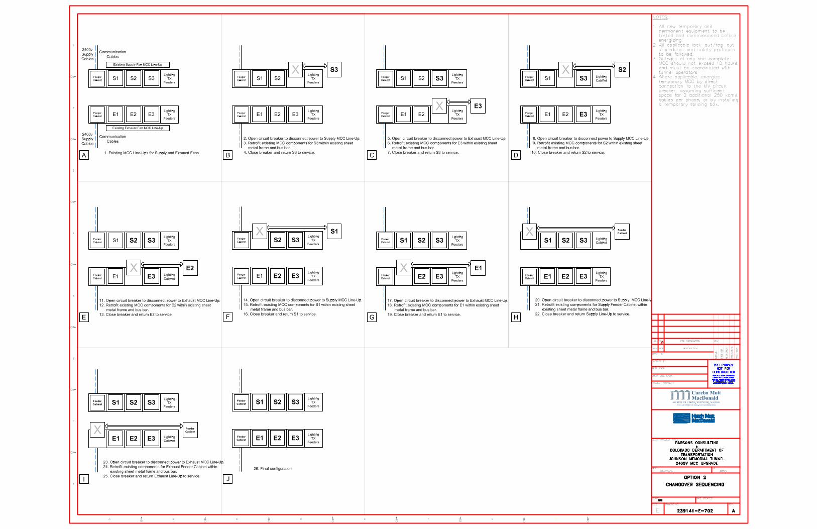
Drawing 239141-E-701 Option 1 Changeover Sequence; Drawing 239141-E-702 Option 2 Changeover Sequence; Drawing 239141-E-703 Option 3 Changeover Sequence, and Drawing 239141-E-704 Option 4 Changeover Sequence.
The purpose of the changeover sequencing plans is to outline the staged sequence of works for each option. By highlighting these steps we set out to raise the issues that will impact operations of the tunnel, such as the number of outages and whether the changeover can be achieved within the design constraints. The sequence plans also ensure that the required level of ventilation fans remain operating during the changeover and that the period a line-up is out of service are evaluated. All of these issues will impact the construction method, costs and schedule..
A detailed description of each sequence follows.
6.2.1 Option 1 – Changeover Sequencing
1. Refer to Drawing 239141-E-701. Install temporary Supply and Exhaust MCC line-ups at the locations identified in drawings 239141-E-300 and 239141-E-301.
2. Energize temporary MCC line-ups. This may be achieved either by direct connection of the 250 kcmils cables to the MV circuit breaker (two cables per phase for a three phases system), or by installing a temporary splicing box.
NOTE: A complete outage of one MCC line-up should not exceed 10 hours. Outage planning should be coordinated with the tunnel operators to minimize impact on high traffic volume times.
3. Open circuit breakers to disconnect power to the suply MCC line-up. Take first supply fan out of service and transfer control to the temporary MCC line–ups. Output cables from existing MCCs to the fan motors to be extended to the temporary cabinets. Test and commission components before closing circuit breaker and returning supply line-up to service. All applicable lock-out/tag-out procedures and safety protocols to be followed.

Preliminary Report
Page 14 of 25
4. Repeat step 3 for the first exhaust fan.
5. Repeat steps 3 and 4 above step for the two remaining pairs of supply and exhaust fans.
6. Open circuit breakers to disconnect power to the supply MCC line-up. Take the lighting transformer feeder cabinets out of service and transfer control to the temporary line-ups. Test and commission components before closing circuit breaker and returning supply line-up to service. All applicable lock-out/tag-out procedures and safety protocols to be followed.
7. Repeat step 6 for the first exhaust lighting transformer feed.
8. Repeat steps 6 and 7 above step for the remaining lighting transformer feeds.
9. Once complete control has been transferred to the temporary MCCs the old (existing) cabinets can be decommissioned and removed.
10. Install and energize two new permanent MCC line-ups on the same footprint as the recently removed equipment.
11. The procedure detailed in steps 3 – 8 can now be followed once again in order to safely transfer fan control and transformer feeders from the temporary MCCs to the new, permanent line-ups.
12. Once complete fan control and transformer feeders has been transferred to the permanent MCCs, the temporary cabinets can be decommissioned and removed. The temporary MCCs can then be relocated to the electrical equipment rooms at the far end of the tunnel where the above procedure can be repeated. This procedure will result in two temporary line-ups remaining at the end of the changeover sequence.
6.2.2 Option 1 – Advantages and Disadvantages The main advantages of selecting this option are:
1. Since the MCC line-up is constructed and tested in the suppliers factory, it will be UL approved before it is shipped to site.
2. When compared with Option 2, this option will result in a reduced labor effort required for switchgear technicians on site.
3. Utilize existing footprint.
4. Minimal disruption to tunnel operation.
5. No sole sourcing required.
The main disadvantages of selecting this option are:

Preliminary Report
Page 15 of 25
1. The temporary MCCs will be removed at the completion of the project, however for a temporary period, the the maintenance access routes will be restricted by the location of the temporary MCC line-ups.HMM has prepared drawing 239141-E-300 West End Option 1 Proposed Temporary MCC Location, which shows there is sufficient space to locate temporary line-ups in the maintenance access routes adjacent to the existing line-ups, Similarly for the East end switch room, HMM has prepared drawing 239141-E-301 East End Option 1 Proposed Temporary MCC Location, which again shows there is sufficient space to locate temporary line-ups adjacent to the existing line-up, which inhibits access space.
2. Six line-ups are required for this option, four will be used for permanent line-ups and two used for temporary at both east and west end switch rooms. At the end of the commissioning, the two remaining MCCs have no future use to CDOT and therefore become redundant. This is a major disadvantage when compared with Options 2, 3 and 4. The level of redundancy could be reduced to a single MCC, by purchasing and using a single line-up during the changeover sequence. While this may provide gains in redundant capital cost, it will likely result in increased labor due to additional testing and commissioning time on site.
3. Existing power supply and communication cables that currently route from the 2.4kV switch panel to each MCC line-up intake panel will require temporary extensions to the temporary line-ups. As identified above, this can likely be achieved either by direct connection of the 250 kcmil cables to the MV circuit breaker (two cables per phase for a three phase system), or by installing a temporary splicing box. In addition, extension cables from the existing MCC line-ups to the motor circuits will also require extension to the temporary line-ups location.
6.2.3 Option 2 – Changeover Sequencing
1. Refer to Drawing 239141-E-702. Open circuit breaker to disconnect power to supply fans MCC line-up. Retrofit MCC components for first supply fan within existing sheet metal frames and bus bars. Test and commission components before closing circuit breaker and returning supply line-up to service.
2. Open circuit breaker to disconnect power to exhaust fans MCC line-ups. Retrofit MCC components for first exhaust fan within existing sheet metal frames and bus bars. Test and commission components before closing circuit breaker and returning exhaust line-up to service.
NOTE: A complete outage of one MCC line-up should not exceed 10 hours. Outage planning should be coordinated with the tunnel operators to minimize impact on high traffic volume times.
3. Repeat steps 1 and 2 for the two remaining pairs of fans to complete the supply and exhaust control changeover.

Preliminary Report
Page 16 of 25
4. Open circuit breaker to disconnect power to supply fans MCC line-up. Retrofit components for supply feeder cabinet within existing sheet metal frames and bus bars. Test and commission components before closing circuit breaker and returning supply line-up to service.
5. Repeat step 4 for the exhaust fan MCC feeder cabinet.
6.2.4 Option 2 – Advantages and Disadvantages The main advantages of selecting this option are:
1. When compared with Option 1 and 4, this option will not require extensions to existing power and communication cables for the intake feeders and the outgoing motor circuits.
2. Availability of space for this option will not present any problems. To illustrate the constraints involved, HMM has prepared drawings 239141-E-303 East End Option 2 and 3 2400V MCC Location Plan, and 239141-E-302 West End Option 2 and 3 2400V MCC Location Plan. As the existing, sheet steel enclosures are retained, the existing MCC line-up footprint are also retained.
3. When compared with Option 1, this option will not result in redundant MCC .
4. Discussions with manufacturers GE and Square D indicate that, the MCC line-ups are likely to be UL approved, however. . .
5. When compared with Option 1 and 4, this option has no restrictions of swing space or restrictions for movement of major items of equipment within the electrical switch rooms during changeover.
The main disadvantages of selecting this option are:
1. When compared with Option 1 and 4, this option will result in additional outages of MCC line-ups since there will not be a new line-up that can be commissioned and made ready for the individual cubicle changeovers;
2. Square D have identified an outage of 16 to 24 hours. These outages are longer than the 10 hour outage tunnel operations can support;
3. When compared with Option 1, 3 and 4, this option will result in the need for additional on site labor. The switchgear technicians will be required on site for longer periods to install each component part and make any necessary adjustments to ensure that the existing sheet shell and bus bars are compatible with the new retrofit component parts. In addition, temporary storage space will be required to locate the component parts on site. This issue is not presented with option 1, 3 and 4 as they will likely be delivered to site as modular units (MCC cubicles) that are ready to be installed; and
4. UL inspection would be required to inspect the completed line-up on site and obtain UL label.

Preliminary Report
Page 17 of 25
6.2.5 Option 3 – Changeover Sequencing
1. Refer to Drawing 239141-E-703. Open feeder air-circuit breakers to disconnect power to the supply MCC line-up. Separate the first supply control cabinet from the bolted bus bar. Complete modular replacement of existing MCC control cabinets (including internal components, sheet metal frame and bus bar section). Reconnect existing control wiring to establish communications to the new MCC. Test and commission components before closing circuit breaker and returning supply line-up to service.
2. Open circuit breakers to disconnect power to the exhaust MCC line-up. Separate the first exhaust control cabinet from the bolted bus bar. Complete modular replacement of existing MCC control cabinets (including internal components, sheet metal frame and bus bar section). Test and commission components before closing circuit breaker and returning exhaust line-up to service.
NOTE: A complete outage of one MCC line-up should not exceed 10 hours. Outage planning should be coordinated with the tunnel operators to minimize impact on high traffic volume times.
If a modular replacement cannot be completed within the 10 hour time frame, temporary jumpers should be used to reconnect the fans on either side of the dislocated bus bar.
3. Repeat steps 1 and 2 for the two remaining pairs of fans and the lighting transformer feeder cabinets to complete the supply and exhaust control changeover.
4. Open circuit breakers to disconnect power to the supply MCC line-up. Separate the supply feeder cabinet from the bolted bus bar. Complete modular replacement of existing feeder cabinet (including internal components, sheet metal frame and bus bar section). Test and commission components before closing circuit breaking and returning line-up to service.
5. Repeat step 4 for the exhaust feeder cabinet.
NOTE: The steps details above, as well as the changeover sequencing illustrated in drawing 239141-E-703, represent the GE installation option. A Square D installation will either require an additional step detailing the modular replacement of the lighting transformer feeder cabinets, or a solution to connect the new to the existing bus bar.
6.2.6 Option 3 – Advantages and Disadvantages The main advantages of selecting this option are:
1. The configuration and location of the existing GE bus bars are such that the existing bus bar can be unbolted and allow a cubicle to be removed and a replacement GE cubicle installed in its place and retain the alignment of the bus bar. This minimizes the need for jumper cables or other transition loops being required when replacing a center located cubicles.

Preliminary Report
Page 18 of 25
2. When compared with Options 1 and 4, this option will not require extensions to existing power and communication cables for the intake feeders and the outgoing motor circuits.
3. Availability of space for this option will not present any problems. HMM has prepared drawings 239141-E-303 East End Option 2 and 3 2400V MCC Location Plan, and 239141-E-302 West End Option 2 and 3 2400V MCC Location Plan. As the existing, sheet steel enclosures are retained, the existing MCC line-up footprints are also retained.
4. When compared with Option 1, this option will not result in redundant MCC line-ups.
5. Our discussions with manufacturers GE and Square D have indicated, the MCC line-up will receive UL approval, unlike Option 2, UL approval is likely to be obtained at the manufacturer’s factory.
6. When compared with Option 2, this option will result in the need for less on site labor since the MCC cabinets will be constructed, assembled, tested and commissioned at the factory.
The main disadvantages of selecting this option are:
1. When compared with Options 1 and 4, this option will result in additional outages of MCC line-ups since there will not be a new line-up that can be commissioned and made ready for the individual cubicle changeovers.
2. If a modular replacement cannot be completed within the 10 hour time frame, temporary jumpers may be required to reconnect the fans on either side of the dislocated bus bar.
3. Unlike Option 2, this option includes the modular replacement of the existing sheet metal cabinet frames and bus bars. Square D have indicated that the retention of the existing lighting transformer feeder cabinets will require a solution to be engineered to connect their new cabinet bus bar to that of the existing feeder cabinet. This issue does not arise with GE equipment and therefore if a workable solution does not become apparent, sole-sourcing of GE equipment may be required in order to retain the lighting feeder transformer cabinets.
6.2.7 Option 4 – Changeover Sequencing
1. Refer to Drawing 239141-E-704. Install new Supply and Exhaust MCC line-ups at the locations identified in drawings 239141-E-304 through 307.
2. Energize new MCC line-ups. This may be achieved either by direct connection of the 250 kcmil cables to the MV circuit breaker (two cables per phase for a three phases system) or by installing a temporary splicing box.
NOTE: A complete outage of one MCC line-up should not exceed 10 hours. Outage planning should be coordinated with the tunnel operators to minimize impact on high traffic volume times.

Preliminary Report
Page 19 of 25
3. Open circuit breakers to disconnect power to the supply MCC line-up. Take first supply fan out of service and transfer control to the new MCC line–up. Output cables from existing MCCs to the fan motors to be extended to the new cabinets. Test and commission components before closing circuit breaker and returning supply line-up to service. All applicable lock-out/tag-out procedures and safety protocols to be followed.
4. Repeat step 3 for the first exhaust fan.
5. Repeat step 3 and 4 for the two remaining pairs of fans to complete the supply and exhaust control changeover.
6. Open circuit breakers to disconnect power to the supply MCC line-up. Take the lighting transformer feeder cabinets out of service and transfer control to the new line-ups. Test and commission components before closing circuit breaker and returning supply line-up to service. All applicable lock-out/tag-out procedures and safety protocols to be followed.
7. Repeat step 6 for the first exhaust lighting feeder.
8. Repeat steps 6 and 7 above step for the remaining lighting transformer feeds.
9. Remove the existing supply MCC power and supply output cables.
10. Once complete fan control has been transferred to the permanent MCCs the old (existing) cabinets can be decommissioned and removed.
6.2.8 Option 4 – Advantages and Disadvantages The main advantages of selecting this option are:
1. Since the MCC line-up is constructed and tested in the suppliers factory, it will be UL approved before it is shipped to site.
2. When compared with Option 2, this option will result in less labor effort required for switchgear technicians on site.
3. When compared with Option 1, this option will not result in redundant MCC line-ups.
4. When compared with Options 2 and 3, this option will not result in additional outages of MCC line-ups.

Preliminary Report
Page 20 of 25
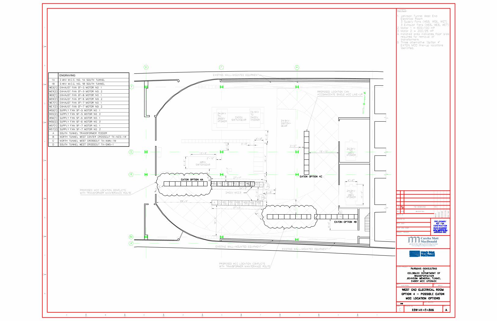
5. HMM has prepared the following drawings to show the possible placement options for two differently sized line-ups as well as the ‘swing space’ required for the maintenance of the other electrical room equipment: 239141-E-304 West End Option 4 – Possible ABB MCC Location Options; 239141-E-305 East End Option 4 – Possible ABB MCC Location Options; 239141-E-306 West End Option 4 – Possible EATON MCC Location Options; 239141-E-307 East End Option 4 – Possible EATON MCC Location Option. As illustrated, a number of potential MCC locations have been identified that do not restrict access for transformer maintenance.
The main disadvantages of selecting this option are:
1. The restrictions of the ‘swing space’ requirements may necessitate the placing of the two MCC line-ups at opposite end of the electrical rooms.
2. Existing power supply cables and communications cables that currently route from the 2.4kV switch panel to each MCC line-up intake panel will require extensions to the new line-up. As identified above, this can likely be achieved by either direct connection of the 250 kcmil cables to the MV circuit breaker (two cables per phase for a three phases system) or by installing a temporary splicing box. In addition, extension cables from the existing MCC line-up to the motor circuits will also require extension to the temporary line-ups location.
6.3 Quantitative Review of Options
A quantitative review of the options has been prepared below whereby the evaluation criteria has been scored for each MCC replacement option out of a possible score of four. A score of one is low, a score of four is high, each criteria holds equal weight.
Options
Evaluation Criteria 1 2 3 4
Maintainability of tunnel operations 3 1 2 3
UL Listing 4 2 3 4
Need for manufacturer to provide site labor 4 1 3 4
Power and communication supply additional splice box/connections 1 4 4 1
Temporary jumper cables 4 4 3 4

Preliminary Report
Page 21 of 25
Extend power and communications cables 2 4 4 1
Redundant MCC 1 4 4 4
Sole sourcing 4 4 4 4
Costs 1 3 4 2
Safety 3 2 2 4
Maintainability 4 3 4 4
Constructability 2 1 4 3
Project Delays 2 1 4 3
Summary 36 38 48 45
Table 6.1: Qualitative Review of Options
Maintainability of tunnel operations is of paramount importance. While it has been agreed that a single MCC line-up may be out of service for a period of 10 hours, the operator will be required to use alternate ventilation modes during this period or implement other traffic management measures to minimize the risk associated with operating the tunnel with less than the full capacity of tunnel ventilation. For Options 2 and 3, each cubicle requires a separate outage, therefore scored lower than Option 1 and 4.
As identified above in advantages and disadvantages, suppliers have advised that UL listing will be provided at the factory for Option 1, 3 and 4. Option 2 scored lowest since UL listing will be provided at site. Square D have indicated that for option 3 UL listing may present some difficulties due to the need to ensure that the existing GE bus bar configuration is compatible with the new Square D location. Given this potential problem , HMM has scored Option 3 lower than Option 1 and 4.
A higher level of site labor will be required for Option 2, therefore scored lowest, followed by Option 3.
Recognizing that Option 1 and 4 will require temporary cable extensions, the differentiator between the two will be the location of the MCC line-ups. Cable extensions are not required for Option 2 and 3, therefore HMM has scored Option 1 the lowest, followed by Option 4. Options 2 and 3 are rated highest as they require no cable extensions. Note that temporary cable extensions for Option 4 will likely require additional lengths of cable when compared with Option 1, therefore scored lower for this criteria.
Jumper cables are only likely to be needed for option 3 in the event that the contractor is unable to changeover a complete MCC cubicle in a single 10 hour outage, therefore Option 3 is scored lower than the remainder options.

Preliminary Report
Page 22 of 25
Option 1 will result in redundant MCC line-ups when compared with the remainder options, therefore, it is rated lower than the rest.
The White Paper prepared to address whether sole sourcing to GE was required concludes that because GE and Square D are able to provide Option 2 and 3, sole sourcing was not required. All options are given an equal score.
A cost review of the Options has been preformed and shows that the lowest cost is :
• Option 3 at $2,712,019;
• Option 2 at $2,827,610;
• Option 4 at $3,132,665, and
• Option 1 at $4,576,400
Further, Option 1 budget at 2006 rates of $3,000,000 have been revised to 2009 rates at a cost of $4,576,400.
Option 2 and 3 present a higher safety risk due to the increased number of outages and exposure to live bus connections Option 1 require more outages than Option 4.
Assuming that all MCC line-ups for Options 1, 3 and 4 are manufactured to the required design and manufacturing standards, the quality of each option is considered equal. Once installed, the maintainability of each option is also considered equal. Options 2 requires equipment to be installed on-site rather than factory assembled, and therefore this option has scored lower for future maintainability.
The least preferred option for constructability is Option 2, this is because all of the electrical components will need to be installed and UL tested on site, whereas Options 1, 3 and 4 will all be manufactured and UL tested at the factory. Option 1 is rated lower than option 4 because of the need for less cable extensions. Option 3 will be constructed at the factory and requires no cable extensions, therefore was scored highest.
The rating for project delays follows closely the rating for constructability. Any constructability challenges will likely result in delays to the construction program.
7 Design Development
In addition to the ten percent design task, the following documents have been prepared for the fifteen percent design submission and included in this document:
• East End Ventilation 2400V MCC One Line Diagram and West Ventilation 2400V MCC One Line Diagram, drawings 239141-E-101 and 102. This drawing identifies the scope of works in One Line Diagram schematic format with protection requirements.

Preliminary Report
Page 23 of 25
• 2400V MCC Schematic Diagram drawing 239141-E-601. This drawing highlights the scope of communications cable replacement works included in this report. The drawing highlights that the cost estimate in this report includes communications cabling upto the East and West Local Control Board. The wiring within the Local Control Boards was not included in the cost estimates, however, HMM understands that this area of scope will need to be included in the next phase of the design.
• A list of Contract Specifications below
CDOT Title CDOT Section Ref Comment
Project Special Provisions & Standard Special Provisions Notice to Bidders Commencement & Completion of Works Contract Goal Contractor Submittals 105 Removal of Structures and Obstructions 202 Relocate Controls and Wiring 210 Environmental health & Safety Management 250 Commissioning Product Requirements General Requirements Common Work Results for Electrical Equipment Wiring Connections Electrical Wire, Cable and Conduit 613 Manufactured Wiring Assemblies Bonding & Grounding 613 Supporting Devices 613 Electrical Pull Boxes 613 Electrical Identification 613
Overcurrent Protective Device Coordination Study
Setting new protective relay on the motors not study all protection
Medium-Voltage Motor Controllers Motor-Control Centers Fuses Enclosed Switches Temporary Power 613 Force Account Items Traffic Control - General Special Construction Requirements Utilities

Preliminary Report
Page 24 of 25
8 Conclusions and Recommendations
The constructability, safety, operational capability, maintainability, space planning, cost and impact to schedule have been summarized in the quantitative review of options, Table 6.1. The lowest score is Option 1 (New MCC line-up with Temporary MCC During Construction) scored 36/52. This was followed by Option 2 (Retrofit Partial Replacement) scored at 38/52, then Option 4 (Full Replacement) scored at 45/52 and finally Option 3 (New Sequenced Modular Replacement) scored highest at 48/52 and is therefore the favored option.
While each criteria in the Table has equal weight, it is likely that safety, constructability and cost will have the greatest impact on the construction schedule and overall delivery of the project.
Option 4 scores highest for safety. Option 2 and 3 present a higher safety risk due to the increased number of outages and exposure to live bus connections. Option 3 will require more outages than Option 4.
Option 3 scores highest for cost, followed by Option 2, Option 4 and Option 1, which was rated with the lowest score.
Option 3 scores highest for constructability. The least preferred option for constructability is Option 2 because all of the electrical components will need to be installed and UL tested on site, whereas Options 1, 3 and 4 will all be manufactured and UL tested at the factory. Based on our qualitative review of the options taking safety, constructability and cost as the major criteria most likely to have the greatest impact on the project schedule, HMM conclude that Option 3 (New Sequenced Modular Replacement) is the preferred option.
It is our recommendation that Option 3 is taken forward to the next detailed stage of the MCC replacement program. Option 3 benefits from the following:
• MCC line-up bus bars can be unbolted and allow a cubicle by multiple equipment suppliers, not GE alone, to be removed and a replaced in the existing MCC line-up footprint;
• When compared with Options 1 and 4, this option will not require extensions to existing power and communication cables for the intake feeders and the outgoing motor circuits;
• This option will not result in redundant MCC line-ups, and;
This option will obtain UL approval because the cubicles are assembled and factory tested at the manufacturers site. Provided that all cubicles are replaced by the manufacturer.

Preliminary Report
Page 25 of 25
9 References
1 Electrical Inspection Report Vol I and II by Parsons Brinkerhoff Quade & Douglas, Inc, June 2006
2 Fire Emergency Ventilation Study, Sverdrup, May 24, 2001
3 Power study performed by PB Americas, May 2007
4 CDOT response to HMM RFI#1, July 15, 2009
5 Minutes of meeting - GE EJMT Site Visit on June 11, 2009
6 White Paper - Sole Sourcing of MCC Equipment July 9, 2009

Preliminary Report
A-1
Appendix A DRAWINGS Reference Title 239141-E-101 East Ventilation 2400V MCC One Line Diagram 239141-E-102 West Ventilation 2400V MCC One Line Diagram 239141-E-300 West End Electrical Room Option 1 Proposed Temporary MCC Locations 239141-E-301 East End Electrical Room Option 1 Proposed Temporary MCC Locations 239141-E-302 West End Electrical Room Option 2 & 3 2400V MCC Location Plan 239141-E-303 East End Electrical Room Option 2 & 3 2400V MCC Location Plan 239141-E-304 West End Electrical Room Option 4 Possible ABB MCC Location Options 239141-E-305 East End Electrical Room Option 4 Possible ABB MCC Location Options 239141-E-306 West End Electrical Room Option 4 Possible Eaton MCC Location Options 239141-E-307 East End Electrical Room Option 4 Possible Eaton MCC Location Options Drawing 239141-E-308 East End Electrical Room 24.9 kV Switchgear Replacement 239141-E-309 West End Electrical Room 24.9 kV Switchgear Replacement 239141-E-601 2400V MCC Schematic Diagram 239141-E-701 Option 1 Changeover Sequence 239141-E-702 Option 2 Changeover Sequence 239141-E-703 Option 3 Changeover Sequence 239141-E-704 Option 4 Changeover Sequence.


Preliminary Report
B-2
Appendix B COST REVIEW

Option 2 Option 3 Option 4
2006 PB 2009 HMM
East Ventilation Building $1,800,000 $2,863,778 $1,415,188 $1,357,073 $1,567,397
West Ventilation Building $1,200,000 $1,712,621 $1,412,422 $1,354,945 $1,565,269
$2,827,610 $2,712,019 $3,132,665
Replacement of 2.4 KV Motor Control Centers - Cost Summary
Option 1
Total $3,000,000 $4,576,400

East Ventilation Building
Quantity Unit Unit Cost Labor Equipment Total Reference Quantity Unit Unit Cost Extension
Temporary Temporary
Temporary 2400V MCC 2 EA 235,000 $470,000 EATON (RS2624/1930) Temporary 2400V MCC 2 EA 129400 $258,800
Cable to Unit Substation 2x250kcmil/ph 14.4 CLF 660.0 251 $13,118 RSMeans* Cable Connection to Unit Substation 120 LF 210 $25,200
Extend Motor Feeders to Temp MCC * Extend Motor Feeders to Temp MCC 6 EA 5760 $34,560
#1/0, 5KV SHLD 7.2 CLF 325.0 198 $3,766 RSMeans
#6, 5KV SHLD 26.4 CLF 168.0 171 $8,950 RSMeans
Cable terminations MCC feeds 24 EA 77.0 47 $2,976 RSMeans
Motor cable terminations at MCC 84 EA 63.5 47 $9,282 RSMeans
Cable splice 1/0 18 EA 129.0 104 $4,194 RSMeans
Cable splice #6 66 EA 124.0 94 $14,388 RSMeans
Cable tray 9" MCC feeds 240 LF 11.6 8 $4,620 RSMeansCable tray 24" 240 LF 17.2 9 $6,216 RSMeans
$54,391
Extend Controls to Temp MCC * Extend Controls to Temp MCC 6 EA 2820 $16,920
9/C #12, 600V 14.4 CLF 103.0 71 $2,506 RSMeans
2/c #12 , 600V 4.8 CLF 27.5 42 $334 RSMeans
Labor - Temporary MCC Installation
Installation of 200HP Starter 6 EA 1,125 $6,750 RSMeans (D5020/175/2900)
Installation of 100HP Starter 6 EA 620 $3,720 RSMeans (D5020/175/2780)
Installation of Lighting Transformer 4 EA 872 $3,488 Ave of 200&100Hp Starters
Installation of Feeder 2 EA 9,300 $18,600 RSMeans (D5010/240/0400)
Testing and Commissioning - Temporart MCC
Assume 10 panels, 2 days each for 2 people @ $47 10 1,504 $15,040 REMeans (Crew R-13, p463)
Reconnect to second MCC 1 EA 24400 $24,400
Labor Adder for level of difficulty, premium time, etc. Labor Adder for level of difficulty, premium time, etc. 1 EA 8800 $8,800
Demolition Demolition
Remove Existing MCC $24,696 Remove Existing MCC 2 LS 11300 $22,600
Remove Conduit and Cable $20,653 Remove Conduit and Cable 140 LF 135 $18,900
Permanent Permanent
2400V MCC 2 EA 235,000 $470,000 EATON 2400V MCC 2 EA 125000 $250,000
Cable to Unit Substation 2x250kcmil/ph Main, Cable Connected 2 EA 1430 $2,860
Extend Motor Feeders to Temp MCC
#1/0, 5KV SHLD Starters 12 EA 440 $5,280
#6, 5KV SHLD Sections 6 EA 660 $3,960
Cable terminations MCC feeds Shipping Splits 3 EA 220 $660
Motor cable terminations at MCC
Cable splice 1/0
Cable splice #6
Cable tray 9" MCC feeds
Cable tray 24"
Extend Controls to Temp MCC
9/C #12, 600V
2/c #12 , 600V
Labor - Permanent MCC Installation
Installation of 200HP Starter 6 EA 1,125 $6,750 RSMeans (D5020/175/2900)
Installation of 100HP Starter 6 EA 620 $3,720 RSMeans (D5020/175/2780)
Installation of Lighting Contactor 4 EA 872 $3,488 Ave of 200&100Hp Starters
Installation of Feeder 2 EA 9,300 $18,600 RSMeans (D5010/240/0400)
Extend Motor Feeders to New Starters Extend Motor Feeders to New Starters 6 EA 8300 $49,800
Labor Adder for level of difficulty, premium time, etc. Labor Adder for level of difficulty, premium time, etc. 1 EA 17600 $17,600
Testing and Commissioning - Permanent MCC
Assume 16 panels, 2 days each for 2 people @ $47ph 16 1,504 $24,064 REMeans (Crew R-13, p463)
Demolition of Temporary Demolition of Temporary
Remove Temporary MCCs $5,901 Remove Temporary MCCs 2 EA 2700 $5,400
Remove Temporary Conduit and Wire $7,758 Remove Temporary Conduit and Wire 1 LS 7100 $7,100
Subtotal $1,173,576 Subtotal $752,840
Mobilization 8% $93,886 Mobilization 8% $60,227Contingency 30% $352,073 Contingency 30% $225,852
Subtotal $1,619,535 Subtotal $1,038,919
Subcontractor Overhead and Profit 20% $323,907 Subcontractor Overhead and Profit 20% $207,784
Subcontractor Total $1,943,442 Subcontractor Total $1,246,703
General Contractor Overhead and Profit 10% $194,344 General Contractor Overhead and Profit 10% $124,670
Total $2,137,786 Total $1,371,373
Design Cost 10% $213,779 Design Cost 10% $137,137
Construction Engineering and Indirects 23.96% $512,214 Engineering/Construction Management Cost 21% $287,988
Total $2,863,778 Total $1,796,499
$1,800,000
LS = Lump Sum
* PB's assumption for these items not known. HMM used price and labor from RSMeans
Replacement of 2.4 KV Motor Control Centers - Option 1, EAST
3% yearly increase of PB
2006 figure
3% yearly increase of PB
2006 figure
PB
PB (Cost Estimate July 2006)
HMM
HMM 2009 East Ventilation Building

West Ventilation Building
Quantity Unit Unit Cost Labor Equipment Total Reference Quantity Unit Unit Cost Extension
Temporary Temporary
Temporary 2400V MCC 2 EA $0 EATON Temporary 2400V MCC 2 EA 4400 $8,800
Cable to Unit Substation 2x250kcmil/ph 14.4 CLF 660.0 251 $13,118 RSMeans* Cable Connection to Unit Substation 120 LF 210 $25,200
Extend Motor Feeders to Temp MCC * Extend Motor Feeders to Temp MCC 6 EA 5760 $34,560
#1/0, 5KV SHLD 7.2 CLF 325.0 198 $3,766 RSMeans
#6, 5KV SHLD 26.4 CLF 168.0 171 $8,950 RSMeans
Cable terminations MCC feeds 24 EA 77.0 47 $2,976 RSMeans
Motor cable terminations at MCC 84 EA 63.5 47 $9,282 RSMeans
Cable splice 1/0 18 EA 129.0 104 $4,194 RSMeans
Cable splice #6 66 EA 124.0 94 $14,388 RSMeans
Cable tray 9" MCC feeds 240 LF 11.6 8 $4,620 RSMeansCable tray 24" 240 LF 17.2 9 $6,216 RSMeans
$54,391
Extend Controls to Temp MCC * Extend Controls to Temp MCC 6 EA 2820 $16,920
9/C #12, 600V 14.4 CLF 103.0 71 $2,506 RSMeans
2/c #12 , 600V 4.8 CLF 27.5 42 $334 RSMeans
Labor - Temporary MCC Installation
Installation of 200HP Starter 6 EA 1,125 $6,750 RSMeans (D5020/175/2900)
Installation of 100HP Starter 6 EA 620 $3,720 RSMeans (D5020/175/2780)
Installation of Lighting Contactor 3 EA 872 $2,616 Ave of 200&100Hp Starters
Installation of Feeder 2 EA 9,300 $18,600 RSMeans (D5010/240/0400)
Testing and Commissioning - Temporart MCC
Assume 10 panels, 2 days each for 2 people @ $47 10 1,504 $15,040 REMeans (Crew R-13, p463)
Reconnect to second MCC 1 EA 24400 $24,400
Labor Adder for level of difficulty, premium time, etc. Labor Adder for level of difficulty, premium time, etc. 1 EA 8800 $8,800
Demolition Demolition
Remove Existing MCC $24,696 Remove Existing MCC 2 LS 11300 $22,600
Remove Conduit and Cable $20,653 Remove Conduit and Cable 140 LF 135 $18,900
Permanent Permanent
2400V MCC 2 EA 235,000 $470,000 EATON 2400V MCC 2 EA 125000 $250,000
Cable to Unit Substation 2x250kcmil/ph Main, Cable Connected 2 EA 1430 $2,860
Extend Motor Feeders to Temp MCC
#1/0, 5KV SHLD Starters 12 EA 440 $5,280
#6, 5KV SHLD Sections 6 EA 660 $3,960
Cable terminations MCC feeds Shipping Splits 3 EA 220 $660
Motor cable terminations at MCC
Cable splice 1/0
Cable splice #6
Cable tray 9" MCC feeds
Cable tray 24"
Extend Controls to Temp MCC
9/C #12, 600V
2/c #12 , 600V
Labor - Permanent MCC Installation
Installation of 200HP Starter 6 EA 1,125 $6,750 RSMeans (D5020/175/2900)
Installation of 100HP Starter 6 EA 620 $3,720 RSMeans (D5020/175/2780)
Installation of Lighting Contactor 3 EA 872 $2,616 Ave of 200&100Hp Starters
Installation of Feeder 2 EA 9,300 $18,600 RSMeans (D5010/240/0400)
Extend Motor Feeders to New Starters Extend Motor Feeders to New Starters 6 EA 8300 $49,800
Labor Adder for level of difficulty, premium time, etc. Labor Adder for level of difficulty, premium time, etc. 1 EA 17600 $17,600
Testing and Commissioning - Permanent MCC
Assume 16 panels, 2 days each for 2 people @ $47ph 16 1,504 $24,064 REMeans (Crew R-13, p463)
Demolition of Temporary Demolition of Temporary
Remove Temporary MCCs $5,901 Remove Temporary MCCs 2 EA 2700 $5,400
Remove Temporary Conduit and Wire $7,758 Remove Temporary Conduit and Wire 1 LS 7100 $7,100
Subtotal $701,832 Subtotal $502,840
Mobilization 8% $56,147 Mobilization 8% $40,227Contingency 30% $210,550 Contingency 30% $150,852
Subtotal $968,528 Subtotal $693,919
Subcontractor Overhead and Profit 20% $193,706 Subcontractor Overhead and Profit 20% $138,784
Subcontractor Total $1,162,234 Subcontractor Total $832,703
General Contractor Overhead and Profit 10% $116,223 General Contractor Overhead and Profit 10% $83,270
Total $1,278,457 Total $915,973
Design Cost 10% $127,846 Design Cost 10% $91,597
Construction Engineering and Indirects 23.96% $306,318 Engineering/Construction Management Cost 21% $192,354
Total $1,712,621 Total $1,199,925
$1,200,000
3% yearly increase of PB
2006 figure
3% yearly increase of PB
2006 figure
Replacement of 2.4 KV Motor Control Centers - Option 1, WEST
HMM PB
West Ventilation Building HMM 2009 PB (Cost Estimate July 2006)

Quantity Unit Unit Cost Labor Equipment Total Reference
Temporary
Temporary 2400V MCC
Cable to Unit Substation 2x250kcmil/ph
Extend Motor Feeders to Temp MCC
#1/0, 5KV SHLD
#6, 5KV SHLD
Cable terminations MCC feeds
Motor cable terminations at MCC
Cable splice 1/0
Cable splice #6
Cable tray 9" MCC feeds
Cable tray 24"
Extend Controls to Temp MCC
9/C #12, 600V
2/c #12 , 600V
Labor - Temporary MCC Installation
Installation of 200HP Starter
Installation of 100HP Starter
Installation of Lighting Transformer
Installation of Feeder
Testing and Commissioning - Temporart MCC
Assume 10 panels, 2 days each for 2 people @ $47
Labor Adder for level of difficulty, premium time, etc.
Demolition
Remove Existing MCC 12 EA 400 $4,800
Remove Conduit and Cable $3,000
Permanent
Retrofit six (6) two speed starters per 2400V MCC 2 EA 240,000 $480,000
Cable to Unit Substation 2x250kcmil/ph
Extend Motor Feeders to New MCC
#1/0, 5KV SHLD
#6, 5KV SHLD
Cable terminations MCC feeds
Motor cable terminations at MCC 84 EA 63.5 47 $9,282
Cable splice 1/0
Cable splice #6
Cable tray 9" MCC feeds
Cable tray 24"
Extend Controls to Temp MCC
9/C #12, 600V
2/c #12 , 600V
New MCC control cable
9/c #12 14.4 CLF 103.0 71 $2,506 RSMeans
2/c #12 4.8 CLF 27.5 42 $334 RSMeans
Installation of Lighting Contactor 75 LF 13.4 8 $1,601 RSMeans
Labor - Permanent MCC Installation
Installation of 200HP Starter 6 EA 1,125 $6,750 RSMeans (D5020/175/2900)
Installation of 100HP Starter 6 EA 620 $3,720 RSMeans (D5020/175/2780)
Installation of Lighting Contactor 4 EA 872 $3,488 Ave of 200&100Hp Starters
Installation of Feeder 2 EA 9,300 $18,600 RSMeans (D5010/240/0400)
Extend Motor Feeders to New Starters
Labor Adder for level of difficulty, premium time, etc. 10 $9,767
Testing and Commissioning - Permanent MCC
Assume 12 panels, 4 days each for 2 people @ $47ph 12 3,008 $36,096 RSMeans (Crew R-13, p463)
Demolition of Temporary
Remove Temporary MCCs
Remove Temporary Conduit and Wire
Subtotal $579,944
Mobilization 8% $46,396Contingency 30% $173,983
Subtotal $800,323
Subcontractor Overhead and Profit 20% $160,065
Subcontractor Total $960,387
General Contractor Overhead and Profit 10% $96,039
Total $1,056,426
Design Cost 10% $105,643
Construction Engineering and Indirects 23.96% $253,120
Total $1,415,188
Add 30% of Labor permanent
MCC Installation Costs
Retrofit Replacement of 2.4 KV Motor Control Centers - Option 2, EAST
HMM
East Ventilation Building HMM 2009
Inclusive of on-site
supervision of installation by
Square D personnel
RSMeans. 6 fans, 2 motors
each, 2 speeds per motor
with 3 phases per speed
plus one common ground.
[6x2x(3+3+1) = 84]

Quantity Unit Unit Cost Labor Equipment Total Reference
Temporary
Temporary 2400V MCC
Cable to Unit Substation 2x250kcmil/ph
Extend Motor Feeders to Temp MCC
#1/0, 5KV SHLD
#6, 5KV SHLD
Cable terminations MCC feeds
Motor cable terminations at MCC
Cable splice 1/0
Cable splice #6
Cable tray 9" MCC feeds
Cable tray 24"
Extend Controls to Temp MCC
9/C #12, 600V
2/c #12 , 600V
Labor - Temporary MCC Installation
Installation of 200HP Starter
Installation of 100HP Starter
Installation of Lighting Transformer
Installation of Feeder
Testing and Commissioning - Temporart MCC
Assume 10 panels, 2 days each for 2 people @ $47
Labor Adder for level of difficulty, premium time, etc.
Demolition
Remove Existing MCC 12 EA 400 $4,800
Remove Conduit and Cable $3,000
Permanent
Retrofit six (6) two speed starters per 2400V MCC 2 EA 240,000 $480,000
Cable to Unit Substation 2x250kcmil/ph
Extend Motor Feeders to Temp MCC
#1/0, 5KV SHLD
#6, 5KV SHLD
Cable terminations MCC feeds
Motor cable terminations at MCC 84 EA 63.5 47 $9,282
Cable splice 1/0
Cable splice #6
Cable tray 9" MCC feeds
Cable tray 24"
Extend Controls to Temp MCC
9/C #12, 600V
2/c #12 , 600V
New MCC control cable
9/c #12 14.4 CLF 103.0 71 $2,506 RSMeans
2/c #12 4.8 CLF 27.5 42 $334 RSMeans
Installation of Lighting Contactor 75 LF 13.4 8 $1,601 RSMeans
Labor - Permanent MCC Installation
Installation of 200HP Starter 6 EA 1,125 $6,750 RSMeans (D5020/175/2900)
Installation of 100HP Starter 6 EA 620 $3,720 RSMeans (D5020/175/2780)
Installation of Lighting Contactor 3 EA 872 $2,616 Ave of 200&100Hp Starters
Installation of Feeder 2 EA 9,300 $18,600 RSMeans (D5010/240/0400)
Extend Motor Feeders to New Starters
Labor Adder for level of difficulty, premium time, etc. 10 $9,506
Testing and Commissioning - Permanent MCC
Assume 12 panels, 4 days each for 2 people @ $47ph 12 3,008 $36,096 REMeans (Crew R-13, p463)
Demolition of Temporary
Remove Temporary MCCs
Remove Temporary Conduit and Wire
Subtotal $578,810
Mobilization 8% $46,305Contingency 30% $173,643
Subtotal $798,758
Subcontractor Overhead and Profit 20% $159,752
Subcontractor Total $958,510
General Contractor Overhead and Profit 10% $95,851
Total $1,054,361
Design Cost 10% $105,436
Construction Engineering and Indirects 23.96% $252,625
Total $1,412,422
Add 30% of Labor permanent
MCC Installation Costs
HMM 2009
Retrofit Replacement of 2.4 KV Motor Control Centers - Option 2, WEST
HMM
East Ventilation Building
Inclusive of on-site
supervision of installation by
Square D personnel
RSMeans. 6 fans, 2 motors
each, 2 speeds per motor
with 3 phases per speed
plus one common ground.
[6x2x(3+3+1) = 84]

Quantity Unit Unit Cost Labor Equipment Total Reference
Temporary
Temporary 2400V MCC
Cable to Unit Substation 2x250kcmil/ph
Extend Motor Feeders to Temp MCC
#1/0, 5KV SHLD
#6, 5KV SHLD
Cable terminations MCC feeds
Motor cable terminations at MCC
Cable splice 1/0
Cable splice #6
Cable tray 9" MCC feeds
Cable tray 24"
Extend Controls to Temp MCC
9/C #12, 600V
2/c #12 , 600V
Labor - Temporary MCC Installation
Installation of 200HP Starter
Installation of 100HP Starter
Installation of Lighting Transformer
Installation of Feeder
Testing and Commissioning - Temporart MCC
Assume 10 panels, 2 days each for 2 people @ $47
Labor Adder for level of difficulty, premium time, etc.
Demolition
Remove Existing MCC 12 EA 400 $4,800
Remove Conduit and Cable $3,000
Permanent
Modular replace six (6) 2-speed starters per MCC 2 EA 242,000 $484,000
Cable to Unit Substation 2x250kcmil/ph
Extend Motor Feeders to New MCC
#1/0, 5KV SHLD
#6, 5KV SHLD
Cable terminations MCC feeds
Motor cable terminations at MCC 84 EA 63.5 47 $9,282
Cable splice 1/0
Cable splice #6
Cable tray 9" MCC feeds
Cable tray 24"
Extend Controls to Temp MCC
9/C #12, 600V
2/c #12 , 600V
New MCC control cable
9/c #12 14.4 CLF 103.0 71 $2,506 RSMeans
2/c #12 4.8 CLF 27.5 42 $334 RSMeans
Installation of Lighting Contactor 75 LF 13.4 8 $1,601 RSMeans
Labor - Permanent MCC Installation
Installation of 200HP Starter 6 EA 1,125 $6,750 RSMeans (D5020/175/2900)
Installation of 100HP Starter 6 EA 620 $3,720 RSMeans (D5020/175/2780)
Installation of Lighting Contactor 4 EA 872 $3,488 Ave of 200&100Hp Starters
Installation of Feeder 2 EA 9,300 $18,600 RSMeans (D5010/240/0400)
Extend Motor Feeders to New Starters
Labor Adder for level of difficulty, premium time, etc.
Testing and Commissioning - Permanent MCC
Assume 12 panels, 2 days each for 2 people @ $47ph 12 1,504 $18,048 REMeans (Crew R-13, p463)
Demolition of Temporary
Remove Temporary MCCs
Remove Temporary Conduit and Wire
Subtotal $556,128
Mobilization 8% $44,490Contingency 30% $166,839
Subtotal $767,457
Subcontractor Overhead and Profit 20% $153,491
Subcontractor Total $920,949
General Contractor Overhead and Profit 10% $92,095
Total $1,013,044
Design Cost 10% $101,304
Construction Engineering and Indirects 23.96% $242,725
Total $1,357,073
RSMeans. 6 fans, 2 motors
each, 2 speeds per motor
with 3 phases per speed
plus one common ground.
[6x2x(3+3+1) = 84]
Inclusive of on-site
supervision of installation by
GE personnel
Modular Replacement of 2.4 KV Motor Control Centers - Option 3, EAST
HMM
East Ventilation Building HMM 2009

Quantity Unit Unit Cost Labor Equipment Total Reference
Temporary
Temporary 2400V MCC
Cable to Unit Substation 2x250kcmil/ph
Extend Motor Feeders to Temp MCC
#1/0, 5KV SHLD
#6, 5KV SHLD
Cable terminations MCC feeds
Motor cable terminations at MCC
Cable splice 1/0
Cable splice #6
Cable tray 9" MCC feeds
Cable tray 24"
Extend Controls to Temp MCC
9/C #12, 600V
2/c #12 , 600V
Labor - Temporary MCC Installation
Installation of 200HP Starter
Installation of 100HP Starter
Installation of Lighting Transformer
Installation of Feeder
Testing and Commissioning - Temporart MCC
Assume 10 panels, 2 days each for 2 people @ $47
Labor Adder for level of difficulty, premium time, etc.
Demolition
Remove Existing MCC 12 EA 400 $4,800
Remove Conduit and Cable $3,000
Permanent
Modular replace six (6) 2-speed starters per MCC 2 EA 242,000 $484,000
Cable to Unit Substation 2x250kcmil/ph
Extend Motor Feeders to Temp MCC
#1/0, 5KV SHLD
#6, 5KV SHLD
Cable terminations MCC feeds
Motor cable terminations at MCC 84 EA 63.5 47 $9,282
Cable splice 1/0
Cable splice #6
Cable tray 9" MCC feeds
Cable tray 24"
Extend Controls to Temp MCC
9/C #12, 600V
2/c #12 , 600V
New MCC control cable
9/c #12 14.4 CLF 103.0 71 $2,506 RSMeans
2/c #12 4.8 CLF 27.5 42 $334 RSMeans
Installation of Lighting Contactor 75 LF 13.4 8 $1,601 RSMeans
Labor - Permanent MCC Installation
Installation of 200HP Starter 6 EA 1,125 $6,750 RSMeans (D5020/175/2900)
Installation of 100HP Starter 6 EA 620 $3,720 RSMeans (D5020/175/2780)
Installation of Lighting Contactor 3 EA 872 $2,616 Ave of 200&100Hp Starters
Installation of Feeder 2 EA 9,300 $18,600 RSMeans (D5010/240/0400)
Extend Motor Feeders to New Starters
Labor Adder for level of difficulty, premium time, etc.
Testing and Commissioning - Permanent MCC
Assume 12 panels, 2 days each for 2 people @ $47ph 12 1,504 $18,048 REMeans (Crew R-13, p463)
Demolition of Temporary
Remove Temporary MCCs
Remove Temporary Conduit and Wire
Subtotal $555,256
Mobilization 8% $44,421Contingency 30% $166,577
Subtotal $766,254
Subcontractor Overhead and Profit 20% $153,251
Subcontractor Total $919,505
General Contractor Overhead and Profit 10% $91,950
Total $1,011,455
Design Cost 10% $101,146
Construction Engineering and Indirects 23.96% $242,345
Total $1,354,945
RSMeans. 6 fans, 2 motors
each, 2 speeds per motor
with 3 phases per speed
plus one common ground.
[6x2x(3+3+1) = 84]
Inclusive of on-site
supervision of installation by
GE personnel
Modular Replacement of 2.4 KV Motor Control Centers - Option 3, WEST
HMM
East Ventilation Building HMM 2009

Quantity Unit Unit Cost Labor Equipment Total Reference
Temporary
Temporary 2400V MCC
Cable to Unit Substation 2x250kcmil/ph
Extend Motor Feeders to Temp MCC
#1/0, 5KV SHLD
#6, 5KV SHLD
Cable terminations MCC feeds
Motor cable terminations at MCC
Cable splice 1/0
Cable splice #6
Cable tray 9" MCC feeds
Cable tray 24"
Extend Controls to Temp MCC
9/C #12, 600V
2/c #12 , 600V
Labor - Temporary MCC Installation
Installation of 200HP Starter
Installation of 100HP Starter
Installation of Lighting Transformer
Installation of Feeder
Testing and Commissioning - Temporart MCC
Assume 10 panels, 2 days each for 2 people @ $47
Labor Adder for level of difficulty, premium time, etc.
Demolition
Remove Existing MCC $24,696
Remove Conduit and Cable $20,653
Permanent
2400V MCC 2 EA 235,000 $470,000 EATON
Cable to Unit Substation 2x250kcmil/ph 14.4 CLF 660.0 251 $13,118 RSMeans
Extend Motor Feeders to New MCC
#1/0, 5KV SHLD 7.2 CLF 325.0 198 $3,766 RSMeans
#6, 5KV SHLD 26.4 CLF 168.0 171 $8,950 RSMeans
Cable terminations MCC feeds 24 EA 77.0 47 $2,976 RSMeans
Motor cable terminations at MCC 84 EA 63.5 47 $9,282 RSMeans
Cable splice 1/0 18 EA 129.0 104 $4,194 RSMeans
Cable splice #6 66 EA 124.0 94 $14,388 RSMeans
Cable tray 9" MCC feeds 240 LF 11.6 8 $4,620 RSMeansCable tray 24" 240 LF 17.2 9 $6,216 RSMeans
$54,391
Extend Controls to Temp MCC
9/C #12, 600V 14.4 CLF 103.0 71 $2,506 RSMeans
2/c #12 , 600V 4.8 CLF 27.5 42 $334 RSMeans
Labor - Permanent MCC Installation
Installation of 200HP Starter 6 EA 1,125 $6,750 RSMeans (D5020/175/2900)
Installation of 100HP Starter 6 EA 620 $3,720 RSMeans (D5020/175/2780)
Installation of Lighting Contactor 4 EA 872 $3,488 Ave of 200&100Hp Starters
Installation of Feeder 2 EA 9,300 $18,600 RSMeans (D5010/240/0400)
Testing and Commissioning - Permanent MCC
Assume 16 panels, 2 days each for 2 people @ $47ph 16 1,504 $24,064 REMeans (Crew R-13, p463)
Extend Motor Feeders to New Starters
Labor Adder for level of difficulty, premium time, etc.
Demolition of Temporary
Remove Temporary MCCs
Remove Temporary Conduit and Wire
Subtotal $642,319
Mobilization 8% $51,386Contingency 30% $192,696
Subtotal $886,400
Subcontractor Overhead and Profit 20% $177,280
Subcontractor Total $1,063,680
General Contractor Overhead and Profit 10% $106,368
Total $1,170,048
Design Cost 10% $117,005
Construction Engineering and Indirects 23.96% $280,344
Total $1,567,397
Replacement of 2.4 KV Motor Control Centers - Option 4, EAST
HMM
East Ventilation Building HMM 2009

Quantity Unit Unit Cost Labor Equipment Total Reference
Temporary
Temporary 2400V MCC
Cable to Unit Substation 2x250kcmil/ph
Extend Motor Feeders to Temp MCC
#1/0, 5KV SHLD
#6, 5KV SHLD
Cable terminations MCC feeds
Motor cable terminations at MCC
Cable splice 1/0
Cable splice #6
Cable tray 9" MCC feeds
Cable tray 24"
Extend Controls to Temp MCC
9/C #12, 600V
2/c #12 , 600V
Labor - Temporary MCC Installation
Installation of 200HP Starter
Installation of 100HP Starter
Installation of Lighting Transformer
Installation of Feeder
Testing and Commissioning - Temporart MCC
Assume 10 panels, 2 days each for 2 people @ $47
Labor Adder for level of difficulty, premium time, etc.
Demolition
Remove Existing MCC $24,696
Remove Conduit and Cable $20,653
Permanent
2400V MCC 2 EA 235,000 $470,000 EATON
Cable to Unit Substation 2x250kcmil/ph 14.4 CLF 660.0 251 $13,118 RSMeans
Extend Motor Feeders to New MCC
#1/0, 5KV SHLD 7.2 CLF 325.0 198 $3,766 RSMeans
#6, 5KV SHLD 26.4 CLF 168.0 171 $8,950 RSMeans
Cable terminations MCC feeds 24 EA 77.0 47 $2,976 RSMeans
Motor cable terminations at MCC 84 EA 63.5 47 $9,282 RSMeans
Cable splice 1/0 18 EA 129.0 104 $4,194 RSMeans
Cable splice #6 66 EA 124.0 94 $14,388 RSMeans
Cable tray 9" MCC feeds 240 LF 11.6 8 $4,620 RSMeansCable tray 24" 240 LF 17.2 9 $6,216 RSMeans
$54,391
Extend Controls to Temp MCC
9/C #12, 600V 14.4 CLF 103.0 71 $2,506 RSMeans
2/c #12 , 600V 4.8 CLF 27.5 42 $334 RSMeans
Labor - Permanent MCC Installation
Installation of 200HP Starter 6 EA 1,125 $6,750 RSMeans (D5020/175/2900)
Installation of 100HP Starter 6 EA 620 $3,720 RSMeans (D5020/175/2780)
Installation of Lighting Contactor 3 EA 872 $2,616 Ave of 200&100Hp Starters
Installation of Feeder 2 EA 9,300 $18,600 RSMeans (D5010/240/0400)
Testing and Commissioning - Permanent MCC
Assume 16 panels, 2 days each for 2 people @ $47ph 16 1,504 $24,064 REMeans (Crew R-13, p463)
Extend Motor Feeders to New Starters
Labor Adder for level of difficulty, premium time, etc.
Demolition of Temporary
Remove Temporary MCCs
Remove Temporary Conduit and Wire
Subtotal $641,447
Mobilization 8% $51,316Contingency 30% $192,434
Subtotal $885,197
Subcontractor Overhead and Profit 20% $177,039
Subcontractor Total $1,062,236
General Contractor Overhead and Profit 10% $106,224
Total $1,168,460
Design Cost 10% $116,846
Construction Engineering and Indirects 23.96% $279,963
Total $1,565,269
Replacement of 2.4 KV Motor Control Centers - Option 4, WEST
HMM
East Ventilation Building HMM 2009

Preliminary Report
C-3
Appendix C WHITE PAPER – SOLE SOURCING REVIEW OF MCC SWITCHGHEAR

P:\PROJECTS\239141 EJMT CO MCC Renewal\200 Reports\201 Project Reports\03 MCC Replacement Study\Issued to CDOT\CDM Task Order No. 3 Draft Sole Sourcing White Paper Final.doc Page 1 of 7
Eisenhower-Johnson Memorial Tunnel (EJMT) 2400v Motor Control Center Refurbishment
Hatch Mott MacDonald White Paper
Sole Sourcing Review of the EJMT’s MCC Switchgear Prepared By: Lionel Lutley & Charles Davis, Hatch Mott MacDonald Date July 9, 2009
Purpose The purpose of this paper is to review whether sole sourcing is necessary for the replacement of 2400v Motor Control Center (MCC) equipment at the EJMT Tunnel, which is located in the State of Colorado. This paper identifies the following:
• Background to the EJMT’s ventilation system; • The MCC replacement alternatives being considered by the Colorado Department
of Transportation (CDOT); • The specific steps taken to determine whether or not sole sourcing is required; and • Conclusions based upon the information that has been developed.
During the meeting of June 2, 2009, CDOT identified its concerns related to energy efficiencies of the existing EJMT ventilation fan motors. In response to CDOT’s concerns Hatch Mott MacDonald (HMM) has identified some of the advantages and disadvantages of installing Variable Frequency Drives (VFDs) as part of the MCC refurbishment.
Background The EJMT’s ventilation system consists of six supply and six exhaust fans. The fans are housed in plant rooms located at each end of the tunnel. The East Ventilation Plant Room houses three supply and three exhaust fans. This arrangement is replicated at the west ventilation plant room. Each fan is driven by two dual-speed motors, with motor one rated 600/100 HP and the second motor rated 200/25 HP. The gear drive units and the CECON (Completely Enclosed for Continuous Operation) clutch, is configured to start the 200/25 HP units first, before the larger 600/100 HP unit begin operations. The larger motors are designed to operate during a fire to provide smoke control. The smaller motors are designed to exhaust vehicle emissions, as well as, smoke in the event of a fire. Under normal conditions, full speed, 600HP, fan operation is not required. The EJMT Fire Emergency Ventilation Study (Sverdrup, May 24, 2001), identifies that under conditions of good visibility, Monday – Friday, tunnel operators switch on two of the 200/25HP fans. During poor visibility, and on Sundays and Holidays, all 12 fans are operated at 100 HP.
P:\PROJECTS\239141 EJMT CO MCC Renewal\200 Reports\201 Project Reports\03 MCC Replacement Study\Issued to CDOT\CDM Task Order No. 3 Draft Sole Sourcing White Paper Final.doc Page 2 of 7
Ventilation requirements in the South (Johnson) Tunnel are generally lower than in the North (Eisenhower) Tunnel. A prevailing West to East wind moves in the direction of traffic in the South Tunnel, and contributes to the tunnel’s ventilation. The tunnel ventilation system can perform smoke control with one fan out of service (EJMT Fire Emergency Ventilation Study, Sverdrup, May 24, 2001). The MCC replacement alternatives under review are:
• Option 1 - New Panels, With Temporary MCC during Construction As identified by the Electrical Inspection Report (PB, July 2006), this option would include the installation of a temporary MCC line-up necessary to maintain tunnel ventilation during the changeover period. The temporary MCC line-up would allow existing MCC functionality to be transferred to the temporary line-up, thus freeing up the existing MCC line-up for permanent replacement. Upon completion, the temporary, redundant MCC line-up would be removed.
• Option 2 - Partial Refurbishment
Option 2 involves the retrofit of existing MCC components and the retention of the existing MCC cubical sheet metal shells. This alternative would involve the refurbishment of the components located in a single MCC cubicle and would utilize the existing MCC footprint.
• Option 3 - New Panels Sequenced (modular replacement)
To allow staged fan operations during construction, this option includes the retrofitting of existing MCC components and sheet metal shells in the existing MCC footprint. This alternative would involve the refurbishment of a single MCC cubicle at a time. The difference between Option 3 and Option 2 is that the sheet shell and main bus is replaced for Option 3.
• Option 4 - Full Refurbishment
Option 4 involves a new MCC line-up that would be located on a new MCC footprint. The new MCC line-up would be commissioned into service and allow existing MCC functionality to be transferred to the new line-up. Upon completion, the existing MCC line-up would be de-commissioned. This alternative requires a new MCC footprint to be made available in the existing Tunnel Services Buildings.
Review of MCC Panels In order to determine whether sole sourcing is necessary, HMM has liaised with the existing MCC manufacture General Electric (GE), as well as alternate switchgear manufacturers; Square-D, Powel and ABB. The objective of these discussions was to confirm whether or not the existing MCC can accommodate the two retrofit alternatives; Options 2 and 3. This liaison was necessary to address technical limitations of retrofitting

P:\PROJECTS\239141 EJMT CO MCC Renewal\200 Reports\201 Project Reports\03 MCC Replacement Study\Issued to CDOT\CDM Task Order No. 3 Draft Sole Sourcing White Paper Final.doc Page 3 of 7
existing equipment, in the existing switchgear footprint. The liaison included component sizing, bus bar compatibility, UL listing and fault ratings.
General Electric GE visited the EJMT on June 25, 2009. The findings of their visit are summarized as follows:
1. Availability of spare parts for the present MCC presents problems as replacement parts are scarce;
2. Existing MCCs are dated 1967, and GE’s latest MCCs are four generations past the existing;
3. Existing 44-inch width is a standard size for this type of equipment; 4. Existing bus very likely to be bolted between sections and not continuous, this
would allow Option 3 be to implemented; 5. Clients preferred down time for a single MCC bus outage was eight hours. A
single fan can be unavailable for a longer period; 6. Option 2 could be accommodated, but would likely require GE technicians on site
to install the components, this results in increased cost for their site presence. In addition, space will need to be made available for local storage of electrical components, work space, tools and equipment;
7. GE can provide a UL listing for the replacement MCCs related to Options 2 and 3;
8. GE was advised of CDOT’s requirement for compliance with the Buy American Act related to the steel cabinets;
9. Programmable Logic Control (PLC) could accommodate the replacement Options 2 and 3;
10. GE seems to recommend going with and is ready to support the implementation of Option 3, and,
11. GE can support Option 1.
Square-D Square-D visited the EJMT on June 25, 2009. Square-D was provided with the pictures of the inside of the cubicles taken by GE. The findings of their visit are summarized as follows:
1. Square-D confirmed they could support Option 2. They indicated that they have worked with GE Limitamp gear before. Square-D indicated this option was labor intensive and would require multiple outages of between 16 and 24 hours;
2. Square-D confirmed they could support Option 3 replacement. Due to differences in bus placement and configuration, temporary transition sections may need to be employed. After all sections have been changed to Square-D gear the new line-up would be located in the same footprint. The need to replace all MCC sections would be constrained by retaining the lighting control cabinets. Square-D believes that this can be done in multiple outages of about 8 to 12 hours;

P:\PROJECTS\239141 EJMT CO MCC Renewal\200 Reports\201 Project Reports\03 MCC Replacement Study\Issued to CDOT\CDM Task Order No. 3 Draft Sole Sourcing White Paper Final.doc Page 4 of 7
3. Square-D preferred supporting a modified Option 1. In this scenario a new MCC utilized for temporary operation at one end (say east) of the tunnel would later be installed permanently at the west end. For this scenario, once the new east MCC line up is commissioned on a temporary basis, the existing east MCC line up could be removed and transferred to the west on a temporary basis. A new final MCC line up could then be installed in the east. Once the west temporary MCC lineup is commissioned, the existing west lineup could be removed allowing a new east lineup, transferred from the east temporary, to be installed in the west as a final location. This would require the purchase of only four new MCCs without the additional expense of a temporary fifth MCC. This modified Option 1 (Option 1A) would require the temporary commissioning followed by decommissioning, relocation and then the permanent commissioning of one new MCC, and the careful decommissioning of one MCC that would be relocated for temporary use;
4. Square-D requested a copy of the PB Power Study and GE drawings. These were e-mailed to Square-D;
5. Square-D indicated that a UL label could be provided for the retro-fitted gear by having an UL inspector evaluate the final assembly. This is most applicable to Option 2.
Powel Powell was provided with the GE drawings of the existing MCCs and some photographs, some of which were taken by GE during their site visit. The findings of their evaluation are summarized as follows:
1. Powell believes that they can come up with something to support either Option 2 or Option 3.
2. Powell has not provided definite details as to how they might be able to support at this time.
ABB ABB was provided with the GE drawings of the existing MCCs and some photographs, some of which were taken by GE during their site visit. The findings of their evaluation are summarized as follows:
1. HMM has yet to receive a reply from ABB regarding their ability to support either Options 2 or 3.
Review of Variable Frequency Drives (VFD) For many applications, VFDs can offer flexible motor control combined with significant electrical energy savings. A VFD manages the supply frequency and voltage, thereby regulating the magnetic flux of an induction motor. Advantages include:

P:\PROJECTS\239141 EJMT CO MCC Renewal\200 Reports\201 Project Reports\03 MCC Replacement Study\Issued to CDOT\CDM Task Order No. 3 Draft Sole Sourcing White Paper Final.doc Page 5 of 7
• Low Inrush Current - By keeping the flux constant, the VFD quickly brings the motor up to full speed while limiting the inrush current, necessary to establish a magnetic field in the core, to 100 to 150 percent of its Full Load Amp (FLA) rating. Typically, the alternative Across-the-Line starting method can draw an inrush current of 600 percent FLA.
• Variable Speed and Reduced Power Consumption – A fan consumes power proportional to the cube of its velocity (3rd Fan Law), therefore a VFD operated fan running at 75 percent of full speed theoretically uses only 42 percent of full load power.
________________________________________________________________________
3rd Fan Law: 3
1
2
1
2⎟⎟⎠
⎞⎜⎜⎝
⎛=
RPMRPM
HPHP
Reduce speed to 75 percent of full RPM: 3
1
2
10075
⎟⎠⎞
⎜⎝⎛=
HPHP
42% of full load power consumed at 75% full RPM: )(42.0 12 HPHP = ________________________________________________________________________ In light of the above, the use of VFDs to start and control twelve fans with dual 600/100HP and 200/25HP motors may appear to represent potentially significant energy savings. However, the following disadvantages have been identified:
• Infrequent Use – The 600HP motors are only used for smoke control in the event of a fire, a typical ventilation mode will operate three exhaust fans at full speed and three supply fans at a reduced speed. Therefore, only six out of twelve fans are operated during a fire scenario. The large motors are started in tandem with the smaller 200/25 HP motors using a CECON clutch.
• Consistency Across System – The existing 480V Eisenhower Tunnel switchgear does not include VFDs. Having a system in place, which combines two sets of dual, two-speed motors with differing methods of motor control, introduces a layer of complexity that currently does not exist.
• Heat, Power Loss – VFDs introduce additional heat losses that currently do not exist. Forced ventilation that is currently not provided in the electrical switch rooms may be required to dissipate this additional heat.
• Harmonics - VFDs introduce harmonics that may affect the power quality of the motor circuits. Mitigating measures such as filter circuits may be required to mitigate harmonics.
• Design changes – The introduction of VFDs will require changes to be made to the existing control and interlocking mechanisms.
• Spacing Limitations – Options 2 and 3 would be contingent upon the ability of the supplier to incorporate the addition of VFD equipment and harmonic filters into the existing cabinet frame sizes. Additional space may also be required to house

P:\PROJECTS\239141 EJMT CO MCC Renewal\200 Reports\201 Project Reports\03 MCC Replacement Study\Issued to CDOT\CDM Task Order No. 3 Draft Sole Sourcing White Paper Final.doc Page 6 of 7
ventilation. Siemens Rebicon’s Medium voltage VFD requires 66”W x 42”D x 110”H without any by-pass contactor.
• The existing motors are 30+ years old, their insulation may not be as good as originally designed. New VFD’s drives will likely be inverter duty designed to have higher insulation values on the windings. The existing motor winding insulation would need to be considered in the VFD design to ensure the motors are not faulted due to voltage spikes during operation.
Conclusions
Sole Sourcing of MCC Equipment
Options 1, 1A and 4: Options 1, 1A and 4 all include the installation of completely new MCC line-ups for which a number of manufacturers capable of fulfilling the requirements have been identified. Option 4 does not requiring sole sourcing since the option involves a new MCC line-up that would be located on a new MCC footprint. All potential vendors are American firms familiar with the Buy American Act.
Sole sourcing of equipment will not be required.
Option 2: GE, the manufacturers of the existing MCC line-ups has confirmed
that they could provide refurbished MCC equipment for the existing cabinet frames (Option 2). Square-D has also confirmed the viability of Option 2 by stating that they could provide refurbished equipment that would fit into the existing cabinet frames. Both GE and Square-D can provide a UL listing.
Sole sourcing of equipment will not be required.
Option 3: GE indicated that they could support Option 3 and provide a
modular replacement of the existing equipment and cabinet frames. In this scenario GE would not be constrained by the retention of the lighting control cabinets. Square-D has also indicated that they could carry out the modular replacement of the full cabinet line-ups in compliance with Option 3. However, at present it is believed that Square-D would be constrained by the retention of lighting control cubicles, but that these constraints could be overcome by the use of temporary transition sections. GE has confirmed that they can provide a UL listing. Whilst not specifically stated, it is likely that Square-D can also provide a UL listing for this option.
Sole sourcing of equipment will not be required.

P:\PROJECTS\239141 EJMT CO MCC Renewal\200 Reports\201 Project Reports\03 MCC Replacement Study\Issued to CDOT\CDM Task Order No. 3 Draft Sole Sourcing White Paper Final.doc Page 7 of 7
As sole sourcing equipment is not deemed to be necessary for Options 1 - 4, a draft letter addressing FHWA concerns and supporting documentation with regard to this issue has not been prepared. In response to the GE and Square-D conclusions above, it is necessary to confirm with the tunnel operator that a single MCC bus downtime of 8 to 12 hours is acceptable, as this will result in full ventilation being unavailable during this period.
Variable Frequency Drives
Any proposal to install VFDs would require the potential energy savings to be compared with the added capital and maintenance costs associated with changing existing controls and interlock designs, making space available for the new VFD equipment and providing forced ventilation and harmonic filters. Based on the above review, it is HMM’s opinion that the realized cost benefit associated with reduced energy use is unlikely to outweigh the additional capital costs.