EIE325: Telecommunication TechnologiesM aciej J. Ogorzałek, PolyU, EIE Telecommunication...
63
EIE325: Telecommunication Technologies Maciej J. Ogorzałek, PolyU, EIE Telecommunication Technologies Week 10 Interfacing
-
date post
21-Dec-2015 -
Category
Documents
-
view
216 -
download
1
Transcript of EIE325: Telecommunication TechnologiesM aciej J. Ogorzałek, PolyU, EIE Telecommunication...

EIE325: Telecommunication Technologies Maciej J. Ogorzałek, PolyU, EIE
Telecommunication Technologies
Week 10
Interfacing

EIE325: Telecommunication Technologies Maciej J. Ogorzałek, PolyU, EIE
Interfacing

EIE325: Telecommunication Technologies Maciej J. Ogorzałek, PolyU, EIE
Characteristics of Interface
Mechanical Connection plugs
Electrical Voltage, timing, encoding
Functional Data, control, timing, grounding
Procedural Sequence of events

Mechanical Specification
EIE325: Telecommunication Technologies Maciej J. Ogorzałek, PolyU, EIE
Electrical Specification
0
1
??????
+3V
-3V

EIE325: Telecommunication Technologies Maciej J. Ogorzałek, PolyU, EIE
Functional Specification
Various functional tasks of interchange circuits data (4) control (16)
transmission (13) loopback testing (3)
timing (3) ground

EIE325: Telecommunication Technologies Maciej J. Ogorzałek, PolyU, EIE
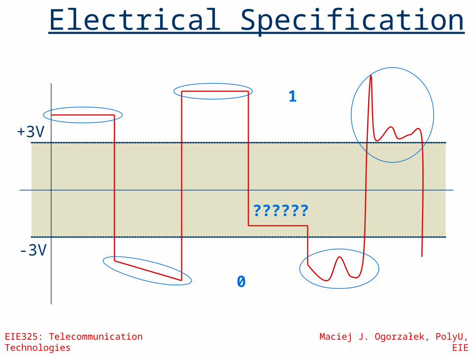
Loopback testing
Provide testing of DCE Fault isolation Common on modern modems Output connected to input – isolated
from the transmission line Remote or Local loopback
EIE325: Telecommunication Technologies Maciej J. Ogorzałek, PolyU, EIE
Local and Remote Loopback
EIE325: Telecommunication Technologies Maciej J. Ogorzałek, PolyU, EIE
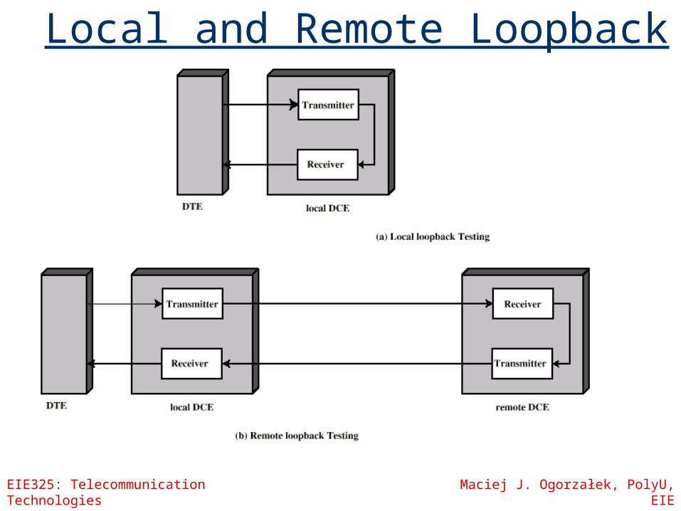
The interchange circuits
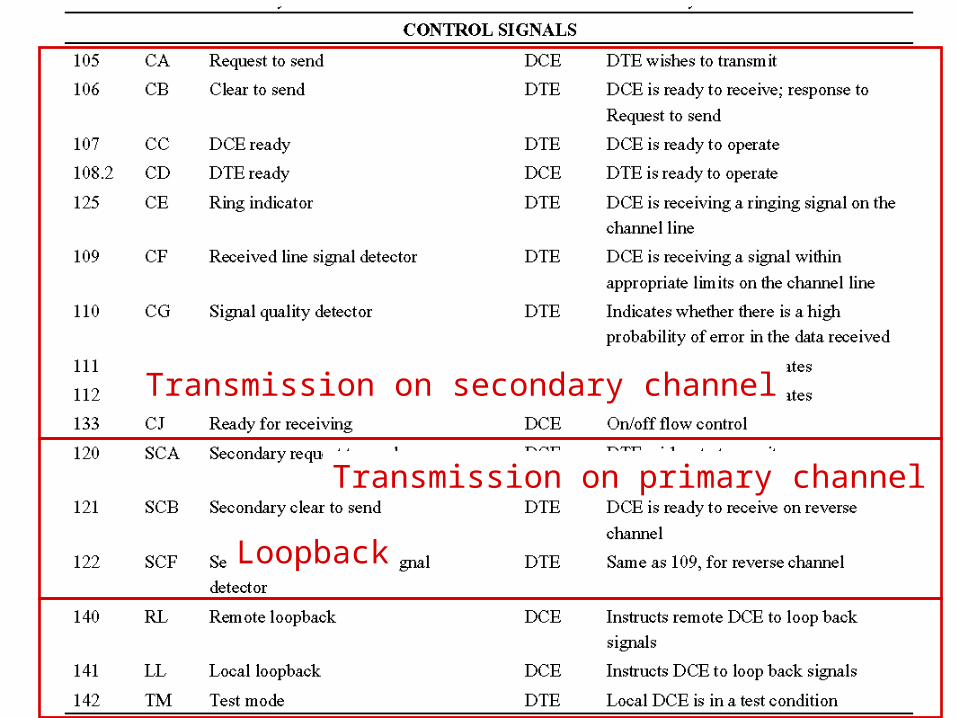
Transmission on primary channel
Transmission on secondary channel
Loopback

EIE325: Telecommunication Technologies Maciej J. Ogorzałek, PolyU, EIE
The interchange circuits
EIE325: Telecommunication Technologies Maciej J. Ogorzałek, PolyU, EIE
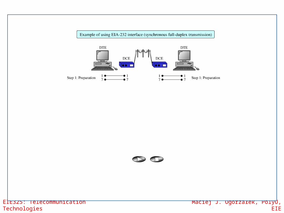
Procedural Specification
Defines the sequence of operation, correct request/response sequences and requirements to send and receive data
EIE325: Telecommunication Technologies Maciej J. Ogorzałek, PolyU, EIE
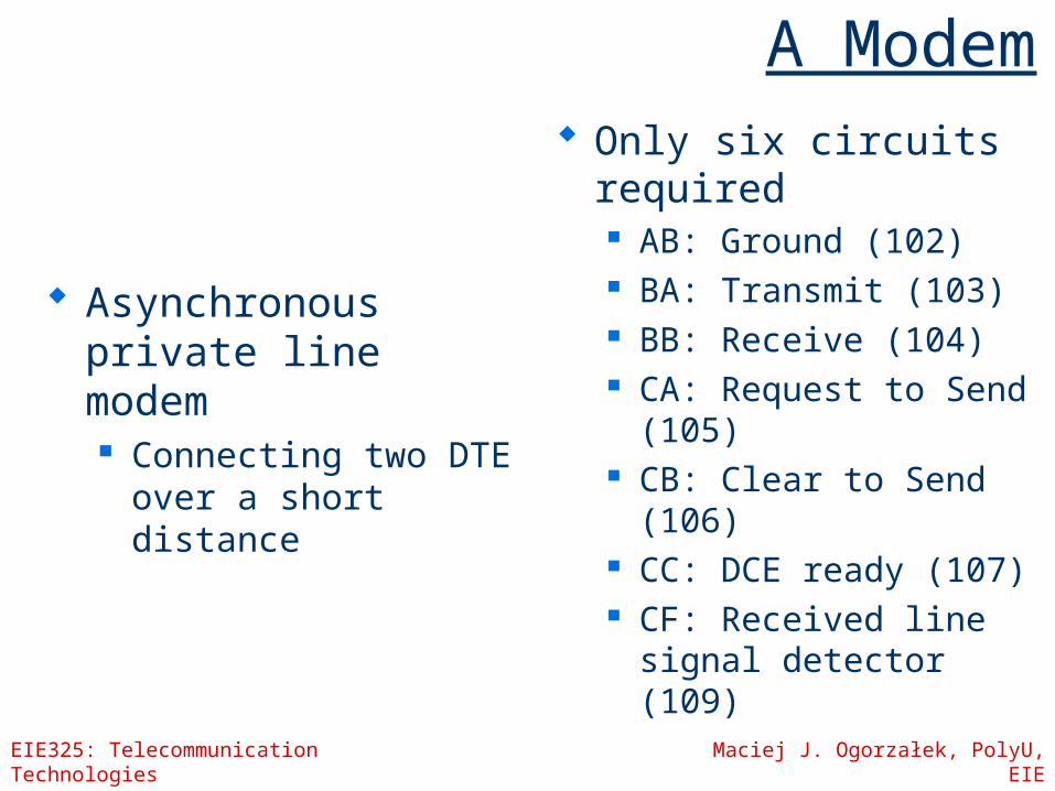
A Modem
Asynchronous private line modem Connecting two DTE
over a short distance
Only six circuits required AB: Ground (102) BA: Transmit (103) BB: Receive (104) CA: Request to Send
(105) CB: Clear to Send
(106) CC: DCE ready (107) CF: Received line
signal detector (109)
EIE325: Telecommunication Technologies Maciej J. Ogorzałek, PolyU, EIE
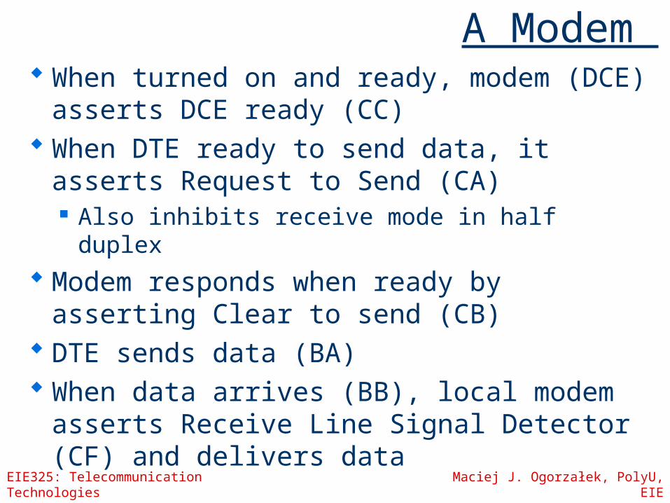
A Modem When turned on and ready, modem
(DCE) asserts DCE ready (CC) When DTE ready to send data, it
asserts Request to Send (CA) Also inhibits receive mode in half duplex
Modem responds when ready by asserting Clear to send (CB)
DTE sends data (BA) When data arrives (BB), local modem
asserts Receive Line Signal Detector (CF) and delivers data

EIE325: Telecommunication Technologies Maciej J. Ogorzałek, PolyU, EIE
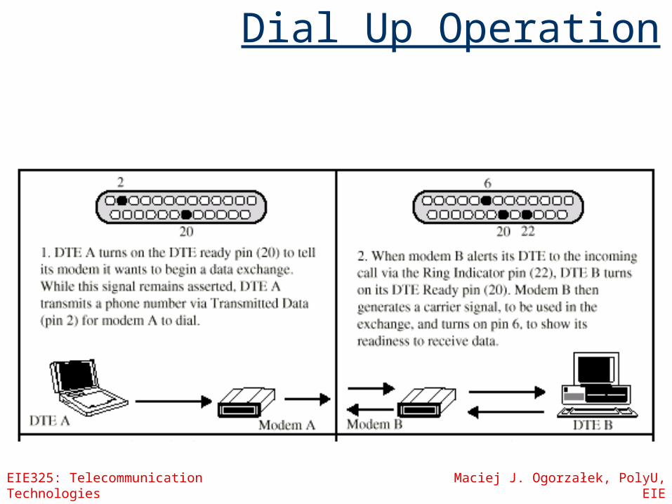
Public line modem
Previous example is insufficient for modem operating on public network
Also need CD: DTE ready (108.2) CE: Ring Indicator (125)
EIE325: Telecommunication Technologies Maciej J. Ogorzałek, PolyU, EIE
Dial Up Operation

EIE325: Telecommunication Technologies Maciej J. Ogorzałek, PolyU, EIE
Dial Up Operation
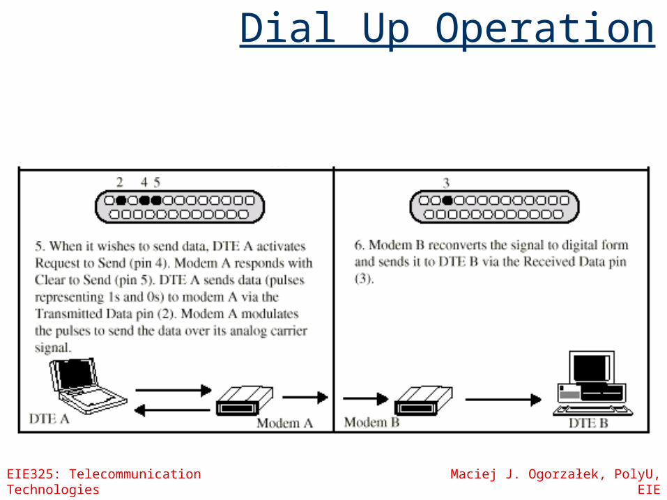
EIE325: Telecommunication Technologies Maciej J. Ogorzałek, PolyU, EIE
Dial Up Operation

HDLC example
EIE325: Telecommunication Technologies Maciej J. Ogorzałek, PolyU, EIE
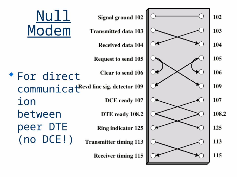
Null Modem
For direct communication between peer DTE (no DCE!)
EIE325: Telecommunication Technologies Maciej J. Ogorzałek, PolyU, EIE
Telecommunication Technologies
Week 10
Multiplexing
EIE325: Telecommunication Technologies Maciej J. Ogorzałek, PolyU, EIE
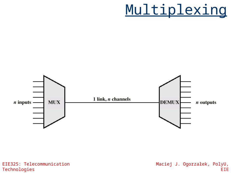
Multiplexing
EIE325: Telecommunication Technologies Maciej J. Ogorzałek, PolyU, EIE
Multiplexing
Frequency Division Multiplexing Wavelength Division Multiplexing
Time Division Multiplexing Synchronous TDM Statistical TDM
Code Division Multiplexing
EIE325: Telecommunication Technologies Maciej J. Ogorzałek, PolyU, EIE
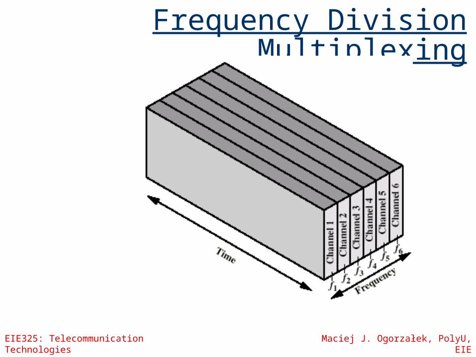
Frequency Division Multiplexing

EIE325: Telecommunication Technologies Maciej J. Ogorzałek, PolyU, EIE
Frequency Division Multiplexing (FDM)
Useful bandwidth of medium exceeds required bandwidth of channel
Each signal is modulated to a different carrier frequency
Carrier frequencies separated so signals do not overlap (guard bands)
NB: Channel allocated even if no data e.g. broadcast radio
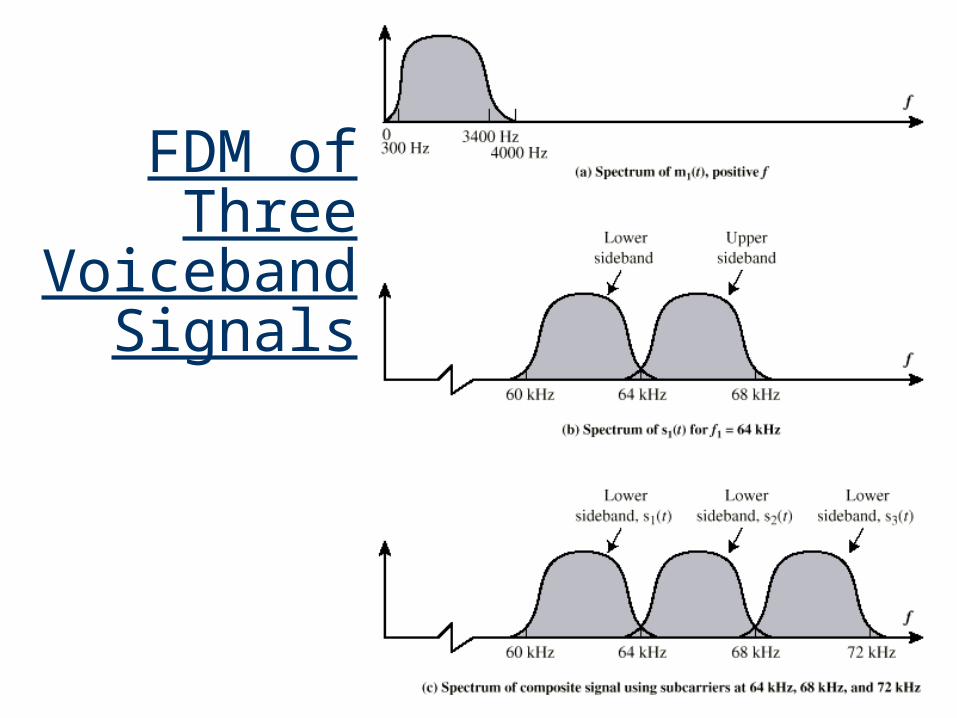
FDM of Three
Voiceband Signals
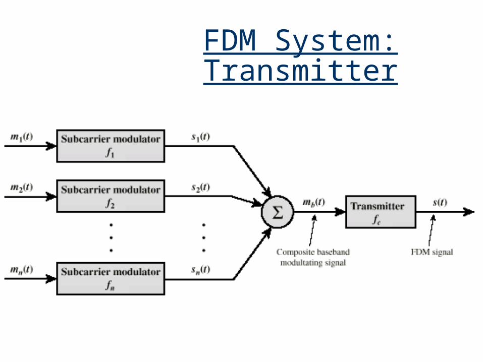
FDM System: Transmitter
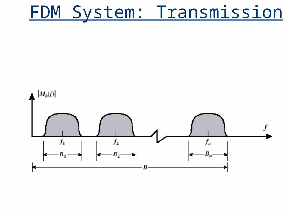
FDM System: Transmission

FDM System: Receiver
EIE325: Telecommunication Technologies Maciej J. Ogorzałek, PolyU, EIE
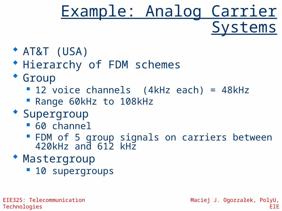
Example: Analog Carrier Systems
AT&T (USA) Hierarchy of FDM schemes Group
12 voice channels (4kHz each) = 48kHz Range 60kHz to 108kHz
Supergroup 60 channel FDM of 5 group signals on carriers between
420kHz and 612 kHz Mastergroup
10 supergroups

EIE325: Telecommunication Technologies Maciej J. Ogorzałek, PolyU, EIE
Asymmetrical Digital Subscriber Line
ADSL Link between subscriber and network
Local loop Uses currently installed twisted pair
cable Can carry broader spectrum 1 MHz or more
EIE325: Telecommunication Technologies Maciej J. Ogorzałek, PolyU, EIE
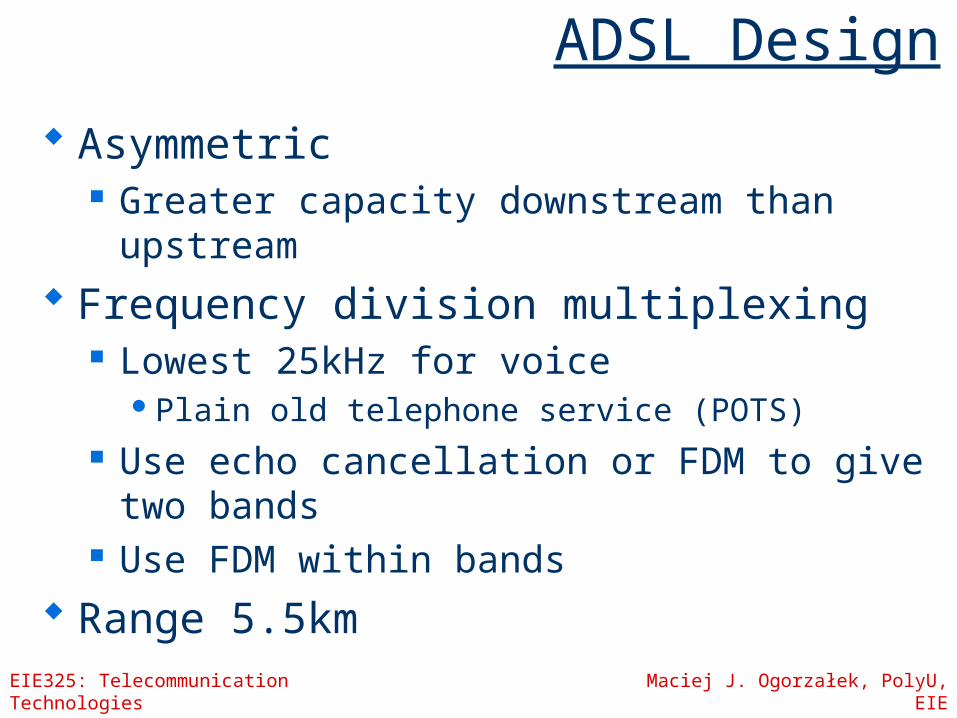
ADSL Design
Asymmetric Greater capacity downstream than
upstream Frequency division multiplexing
Lowest 25kHz for voicePlain old telephone service (POTS)
Use echo cancellation or FDM to give two bands
Use FDM within bands Range 5.5km

EIE325: Telecommunication Technologies Maciej J. Ogorzałek, PolyU, EIE
ADSL Channel Configuration

EIE325: Telecommunication Technologies Maciej J. Ogorzałek, PolyU, EIE
xDSL
High data rate DSL (HDSL) 2Mbps over two twisted pair lines BW of less than 200kHz
Single line DSL (SDSL) Single twisted pair Echo cancellation
Very high data rate DSL (VDSL) New: increase data rate at the expense of
distance
EIE325: Telecommunication Technologies Maciej J. Ogorzałek, PolyU, EIE
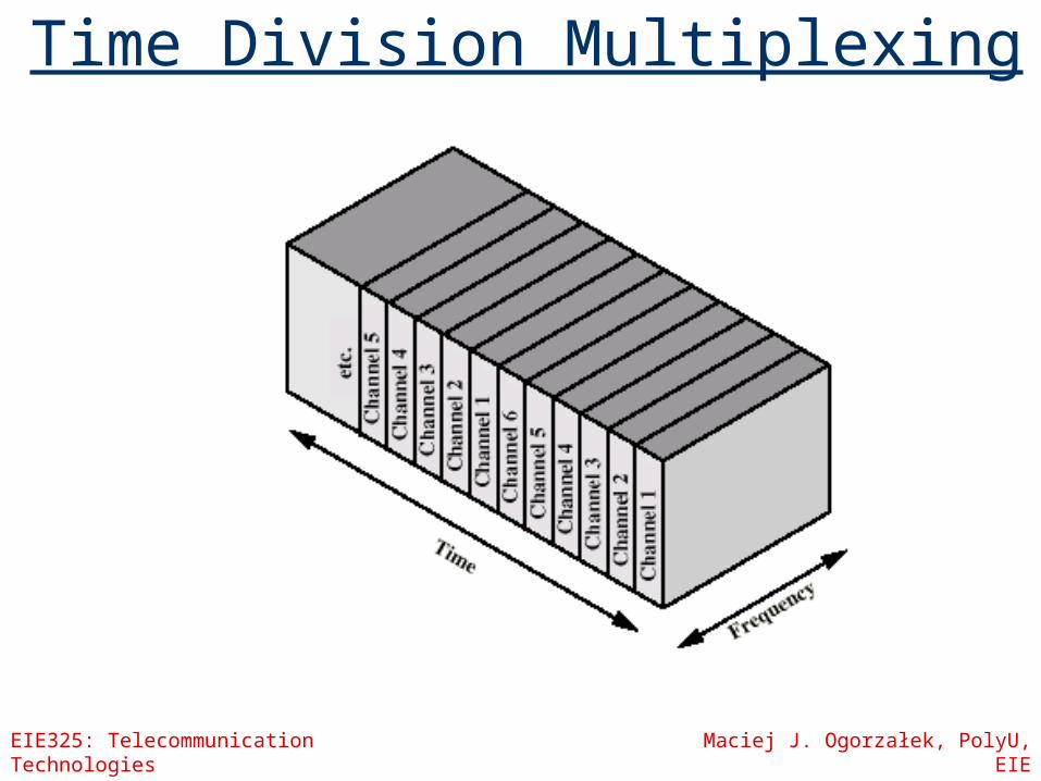
Time Division Multiplexing

TDM System
EIE325: Telecommunication Technologies Maciej J. Ogorzałek, PolyU, EIE
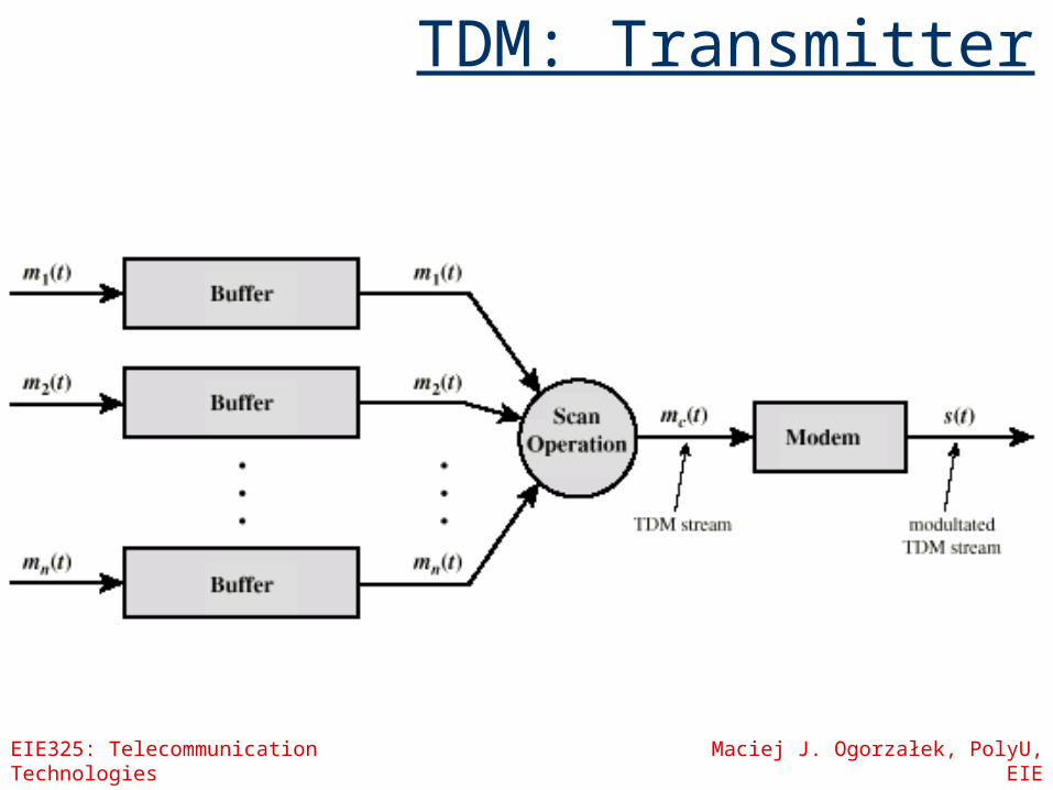
TDM: Transmitter
EIE325: Telecommunication Technologies Maciej J. Ogorzałek, PolyU, EIE
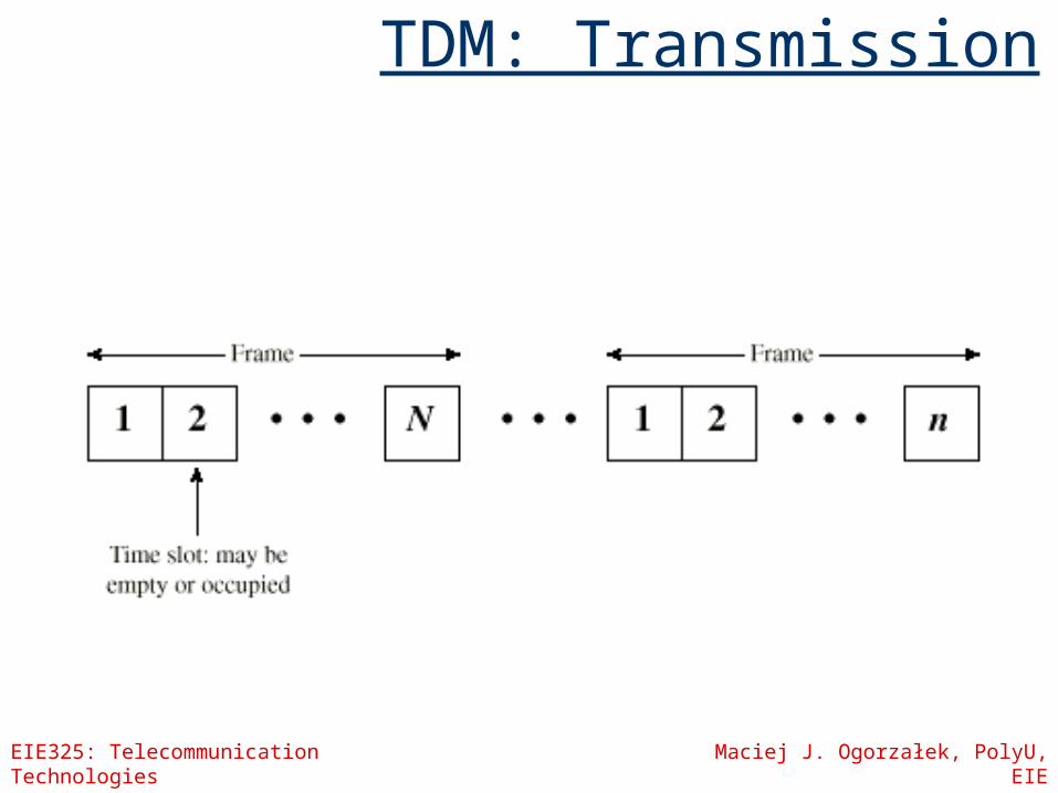
TDM: Transmission
EIE325: Telecommunication Technologies Maciej J. Ogorzałek, PolyU, EIE
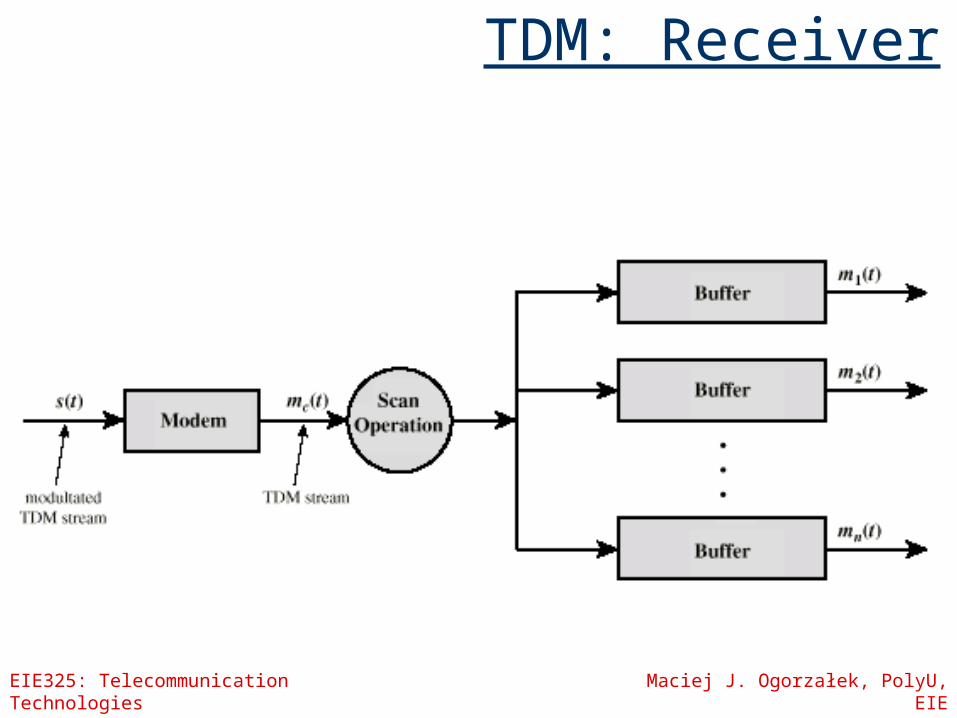
TDM: Receiver
EIE325: Telecommunication Technologies Maciej J. Ogorzałek, PolyU, EIE
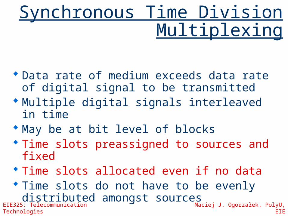
Synchronous Time Division Multiplexing
Data rate of medium exceeds data rate of digital signal to be transmitted
Multiple digital signals interleaved in time May be at bit level of blocks Time slots preassigned to sources and
fixed Time slots allocated even if no data Time slots do not have to be evenly
distributed amongst sources
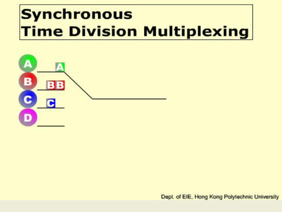
Synchronous TDM
EIE325: Telecommunication Technologies Maciej J. Ogorzałek, PolyU, EIE
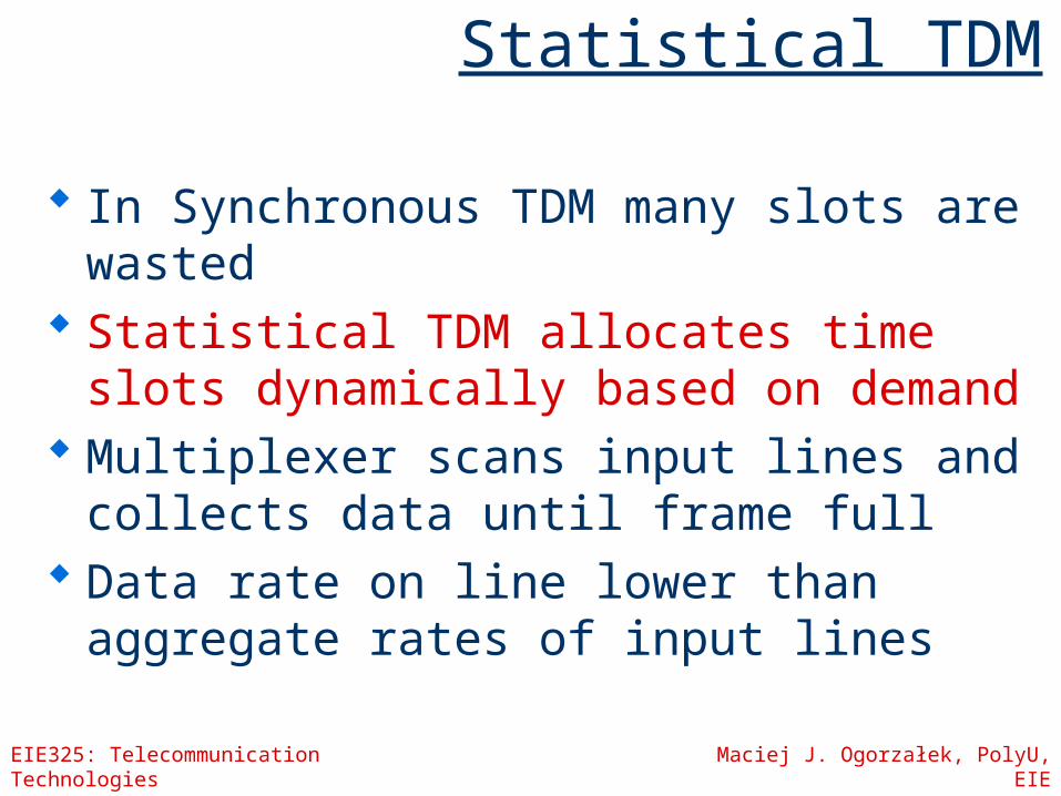
Statistical TDM
In Synchronous TDM many slots are wasted
Statistical TDM allocates time slots dynamically based on demand
Multiplexer scans input lines and collects data until frame full
Data rate on line lower than aggregate rates of input lines

Statistical TDM

An international brokerage firm has its head office in Hong Kong, and a smaller branch office in Singapore. The firm's interests lie in trading on the futures markets of Hong Kong, London, and New York; and data related to these trades should be communicated over a private leased line between Hong Kong and Singapore. The company finds that a single leased line between Hong Kong and Singapore is insufficient for its needs. Instead, the Hong Kong, London and New York trading arms each maintain a separate link and these three lines are multiplexed together for transmission between Hong Kong and Singapore. Each of these three lines is utilised 24 hours per day, but varies according to the following table:
Compute the capacity required on the multiplexed line using:(i) synchronous time division multiplexing.(ii) statistical time division multiplexing if 5% of
capacity is required for framing overhead.
Expected Link Usage (kbps) 9am – 5pm 5pm – 1am 1am – 9amHK trading line 12 1 3London trading line 5 19 3New York trading line 1 4 21

EIE325: Telecommunication Technologies Maciej J. Ogorzałek, PolyU, EIE
Synchronous vs. Statistical TDM
EIE325: Telecommunication Technologies Maciej J. Ogorzałek, PolyU, EIE
TDM Link Control
No headers and tails Data link control protocols not needed Flow control
Data rate of multiplexed line is fixed If one channel receiver cannot receive data, the
others must carry on The corresponding source must be quenched This leaves empty slots
Error control Errors are detected and handled by individual
channel systems

Data Link Control on TDM
Inputs:
Transmission:

EIE325: Telecommunication Technologies Maciej J. Ogorzałek, PolyU, EIE
Framing
No flag or SYNC characters bracketing TDM frames Must provide synchronising mechanism Added digit framing
One control bit added to each TDM frame Looks like another channel - “control channel”
Identifiable bit pattern used on control channel e.g. alternating 01010101…unlikely on a data channel Can compare incoming bit patterns on each channel with
sync pattern

EIE325: Telecommunication Technologies Maciej J. Ogorzałek, PolyU, EIE
Pulse Stuffing
Problem - Synchronising data sources Clocks in different sources drifting Data rates from different sources not related
by simple rational number Solution - Pulse Stuffing
Outgoing data rate (excluding framing bits) higher than sum of incoming rates
Stuff extra dummy bits or pulses into each incoming signal until it matches local clock
Stuffed pulses inserted at fixed locations in frame and removed at demultiplexer

TDM of Analog and Digital Sources

EIE325: Telecommunication Technologies Maciej J. Ogorzałek, PolyU, EIE
Examples: Digital Carrier Systems
Hierarchy of TDM USA/Canada/Japan use one system ITU-T use a similar (but different)
system US system based on DS-1 format Multiplexes 24 channels Each frame has 8 bits per channel plus
one framing bit 193 bits per frame

EIE325: Telecommunication Technologies Maciej J. Ogorzałek, PolyU, EIE
Digital Carrier Systems
For voice each channel contains one word of digitised data (PCM, 8000 samples per sec) Data rate 8000x193 = 1.544Mbps Five out of six frames have 8 bit PCM samples Sixth frame is 7 bit PCM word plus signaling bit Signalling bits form stream for each channel
containing control and routing info Same format for digital data
23 channels of data 7 bits per frame plus indicator bit for data or systems
control 24th channel is sync
EIE325: Telecommunication Technologies Maciej J. Ogorzałek, PolyU, EIE
Mixed Data
DS-1 can carry mixed voice and data signals
24 channels used No sync byte Can also interleave DS-1 channels
DS-2 is four DS-1 giving 6.312Mbps
EIE325: Telecommunication Technologies Maciej J. Ogorzałek, PolyU, EIE
ISDN (Integrated Services Digital Network)
User Network Interface(digital telephony+data transport services
= voice,data, text, graphics,music, video and other sources over telephone wires)
ISDN allows multiplexing of devices over single ISDN line
Two interfaces Basic ISDN Interface Primary ISDN Interface

EIE325: Telecommunication Technologies Maciej J. Ogorzałek, PolyU, EIE
Basic ISDN Interface
Digital data exchanged between subscriber and NTE - Full Duplex
Separate physical line for each direction Pseudoternary coding scheme
1=no voltage, 0=positive or negative 750mV +/-10%
Data rate 192kbps Basic access is two 64kbps B channels and
one 16kbps D channel This gives 144kbps multiplexed over 192kbps Remaining capacity used for framing and
sync

EIE325: Telecommunication Technologies Maciej J. Ogorzałek, PolyU, EIE
Basic ISDN Interface
B channel is basic user channel Data PCM voice Separate logical 64kbps connections for
different destinations D channel used for control or data
LAPD frames Each frame 48 bits long One frame every 250s
EIE325: Telecommunication Technologies Maciej J. Ogorzałek, PolyU, EIE
Primary ISDN
Point to point Typically supporting PBX 1.544Mbps
Based on US DS-1 Used on T1 services 23 B plus one D channel
2.048Mbps Based on European standards 30 B plus one D channel Line coding is AMI using HDB3

EIE325: Telecommunication Technologies Maciej J. Ogorzałek, PolyU, EIE
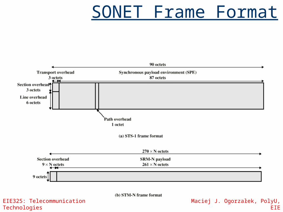
Sonet/SDH
Synchronous Optical Network (ANSI) Synchronous Digital Hierarchy (ITU-T) Compatible Signal Hierarchy
Synchronous Transport Signal level 1 (STS-1) or Optical Carrier level 1 (OC-1)
51.84Mbps Carry DS-3 or group of lower rate signals (DS1
DS1C DS2) plus ITU-T rates (e.g. 2.048Mbps) Multiple STS-1 combined into STS-N signal ITU-T lowest rate is 155.52Mbps (STM-1)
EIE325: Telecommunication Technologies Maciej J. Ogorzałek, PolyU, EIE
SONET Frame Format
EIE325: Telecommunication Technologies Maciej J. Ogorzałek, PolyU, EIE
Code Division Multiplexing
CDMA: Code division Multiple Access TDM and FDM work in either time or
frequency space… CDMA is a combination of both
Each user is given a unique sequence (code) and transmits messages using that sequence orthogonal pseudo-random

EIE325: Telecommunication Technologies Maciej J. Ogorzałek, PolyU, EIE
FDM, TDM and CDMA
Time
Freq
uenc
y
CDMA
FDM
Time
Freq
uenc
y
TDM
TimeFr
eque
ncy
Time
Freq
uenc
y
Time
Freq
uenc
y
EIE325: Telecommunication Technologies Maciej J. Ogorzałek, PolyU, EIE
How?
Each bit is represented by a “chip” of G bits
The chips are combined and transmitted
At the other end they may be recovered
Either mutually orthogonal mutually “random”