
EIC at JLab - design considerations and detector overvie · EIC at JLab - design considerations and...
35
EIC at JLab - design considerations and EIC at JLab - design considerations and detector overview detector overview Pawel Nadel-Turonski Pawel Nadel-Turonski Jefferson Lab, Newport News, VA Jefferson Lab, Newport News, VA EIC Exclusive Workshop, 14 March 2010, Rutgers EIC Exclusive Workshop, 14 March 2010, Rutgers
Transcript of EIC at JLab - design considerations and detector overvie · EIC at JLab - design considerations and...

EIC at JLab - design considerations and EIC at JLab - design considerations and detector overviewdetector overview
Pawel Nadel-TuronskiPawel Nadel-TuronskiJefferson Lab, Newport News, VAJefferson Lab, Newport News, VA
EIC Exclusive Workshop, 14 March 2010, RutgersEIC Exclusive Workshop, 14 March 2010, Rutgers

14 March 2010
Outline
1. Introduction1. Introduction
2. Exclusive kinematics and Detector Requirements2. Exclusive kinematics and Detector Requirements
3. Interaction Region and Detector Concepts3. Interaction Region and Detector Concepts

14 March 2010
Why a collider?
• s = 4EeEp for colliders (e.g., 4 x 9 x 60 = 2160 GeV2)
• s = 2EeMp for fixed target experiments (e.g., 2 x 11 x 0.938 = 20 GeV2)
• Unpolarized FOM = Rate = Luminosity · Cross Section · Acceptance• Polarized FOM = Rate · (Target Polarization)2 · (Target Dilution)2
• No dilution and high ion polarization (also transverse)• No current (luminosity) limitations, no holding fields (acceptance)• No backgrounds from target (Møller electrons)
Easier to reach high CM energies (EEasier to reach high CM energies (Ecmcm22 = s) = s)
Spin physics with high figure of meritSpin physics with high figure of merit
Easier detection of reaction productsEasier detection of reaction products• Can optimize kinematics by adjusting beam energies
– Laws of physics do not depend on reference frame, but measured uncertainties do!• More symmetric kinematics improve acceptance, resolution, particle identification, etc• Access to neutron structure with deuteron beams through spectator tagging (pp ≠ 0)

14 March 2010
Past and future e-p and e-A colliders
HERA, Hamburg, 1992-200727 GeV e on 920 GeV p, L = 5 x 1031
LHeC, CERN, Geneva
Brookhaven, Upton, NYJefferson Lab, Newport News, VA
EIC

14 March 2010
Kinematic coverage
• Medium-energy EIC– Overlaps with and is complementary to the LHeC (both JLab and BNL versions)– Overlaps with JLab 12 GeV (JLab version)– Provides high luminosity and excellent polarization for the range in between
• Currently only low-statistics fixed-target data available in this region
-
x
Medium-energy EIC (JLab version)
s (CM energy)
Q2 ~ xys

14 March 2010
Lum
inos
ity [
cm-2 s-1
]
1035
1034
1033
1032
10 100 1000 10000 100000
COMPASS
JLAB6&12HERMESENC@GSI
(M)EICMeRHIC
DIFFDIS
EWDES
JETSSIDIS
s [GeV2]
C. Weiss
s
R. Ent
Physics, kinematic coverage, and luminosity
• Right plot (L vs. s) is a projection on the diagonal of the left one (Q2 vs. x)
saturation in nuclei?

14 March 2010
• MEIC = EIC@JLAB– 1-2 high-luminosity detectors
• Luminosity ~ 1034 cm-2s-1
• Low backgrounds
– Special detector?
• ELIC = high-energy EIC@JLab– Future upgrade?
300 m
400 m
Electron energy: 3-11 GeVProton energy: 20-60 GeV
s = 250 - 2650 GeV2
Can operate in parallelwith fixed-target program
MEIC@JLab – Detector Layout
Special IP?
p p
ee

14 March 2010
Hadronic background – comparison with HERA
• Dominated by interaction of beam ions with residual gas• Worst case at maximum energy
• Distance from arc to IP: 30 m / 120 m = 0.25• Average hadron multiplicity: (2640 / 100000)1/4 = 0.4• p-p cross section (fixed target): σ(60 GeV) /σ(920 GeV) = 0.7• At the same current and vacuum, MEIC background is 7% of HERA
Random backgroundRandom background
Comparison of MEIC (11 on 60 GeV) and HERA (27 on 920 GeV)Comparison of MEIC (11 on 60 GeV) and HERA (27 on 920 GeV)
Hadronic background is not a problem for the MEICHadronic background is not a problem for the MEIC• At constant vacuum the MEIC can run 1.4 A with comparable background• Vacuum is much easier to maintain in a short section of a small ring• MEIC luminosity is more than 100 times higher (depending on kinematics)• Signal-to-background will be considerably better at the MEIC

12 November 2009 9
Diffractive and SIDIS mesons4 on 250 GeV4 on 50 GeV
diff
ract
ive
DIS
• Both reactions produce high-momentum mesons at small angles
• For exclusive reactions, this constitutes our background!

12 January 2009 10
Exclusive meson kinematics
• Meson kinematics integrated over all Q2
– Vertical lines at 30° (possibly up to 40°) indicate transition from central barrel to endcaps
– Horizontal line indicates maximum meson momentum for π/K separation with a DIRC
• Problem: cross section falls rapidly with Q2 – Higher Q2 is needed due to factorization requirements for GPD
determination, but plots shown are dominated by photoproduction.
Tanja Horn
ep → e'π+n
4 on 12 GeV 4 on 30 GeV 4 on 250 GeV

12 January 2009 11
Exclusive meson kinematics at higher Q2
Tanja Horn
4 on 250 GeV4 on 30 GeV
no Q2 cut no Q2 cut
Q2 > 10 GeV2Q2 > 10 GeV2
• The meson momentum distribution has a strong Q2-dependence
• DIRC not useful at 250 GeV.
• No mesons at small angles where solenoid resolution is poor (both kinematics).
• Momentum resolution (dp/p ~ p from tracking), a challenge at 250 GeV

14 March 2010
Exclusive light meson kinematics (Q2 > 10 GeV2)
Tanja Horn
recoil baryonsscattered electronsmesons
4 on
250
GeV
4 on
30
GeV
Θ ~ √t/Ep
PID challenging
very high momenta
electrons in central barrel, but p different
0.2° - 0.45°
0.2° - 2.5°
ep → e'π+n

12 January 2009 13
“Symmetric” kinematics – 4 on 30 GeV
Tanja Horn
ep → e'π+n
recoil baryonsscattered electronsmesons
no Q
2 cut
Q2 >
10
GeV
2
t-distribution unaffected
forward mesons: low Q2, high p
low-Q2 electrons in electron endcap
high-Q2 electrons in central barrel:
1-2 < p < 4 GeV
mesons in central barrel:
2 < p < 4 GeV
Beam divergence Θ ~ 1/√(β*)

12 January 2009 14
DES at higher electron energies
• With 12 GeV CEBAF, MEIC@JLab has the option of using higher electron energies– DIRC no longer sufficient for π/K separation
• RICH would extend the minimum diameter of solenoid from approximately 3 to 4 m– Main constraint since bore angle is not an issue in JLab kinematics
4 on 30 GeV
s = 480 GeV2
5 on 50 GeV
s = 1000 GeV2
(10 on 50 GeV)
s = 2000 GeV2
• RICH based on ALICE design might push the limit from 4 to 7 GeV– Requires a more detailed study
Q2 >
10
GeV
2

12 January 2009 15
1. (Crab) crossing angle and symmetric kinematics1. (Crab) crossing angle and symmetric kinematics
2. Detector Challenges2. Detector Challenges
3. Interaction Region challenges3. Interaction Region challenges
• Allow a compact, hermetic forward ion detector• Can be used to eliminate synchrotron radiation• Produce electron and meson momenta comparable to CLAS
– Good momentum resolution– Good particle identification
• Quad gradients and apertures• Chromatic corrections (~ f/β*) limit βmax to ~ 2.5 km
• Optimization of forward ion detection• PID at higher electron energies (5-10 GeV)• Beam divergence and transverse momentum spread
DES detector and Interaction Region concepts

14 March 2010
400
Wed Mar 03 20:04:34 2010 OptiM - MAIN: - C:\Working\ELIC\MEIC\Optics\IR\ion\p_7m_tri_LR_1.opt
3000
0
50
BE
TA
_X
&Y
[m]
DIS
P_X
&Y
[m]
BETA_X BETA_Y DISP_X DISP_Y
*
*
20
2x
y
cmcm
β
β
=
=
l* = 7m
IP
FF triplet
f
*3
*2 2
3
720 10
2.5 10ff mββ −≈ = ≈
××l
Q3 Q2 Q1
400
Wed Mar 03 20:26:30 2010 OptiM - MAIN: - C:\Working\ELIC\MEIC\Optics\IR\ion\p_7m_tri_LR_1_20GeV.opt
0.5
0
0.5
0
Siz
e_X
[cm
]
Siz
e_Y
[cm
]
Ax_bet Ay_bet Ax_disp Ay_disp
IP
20 GeV
Q1 G[T/m] = -38 to -115Q2 G[T/m] = 33 to 99Q3 G[T/m] = -33 to -100
Gradients: 20 - 60 GeV
Ion quadrupole apertures (preliminary optics)
Beam size (σ): up to 5 mmAperture (r): 10-15 σPeak field (rG): up to 7T
• Beam size: σ = √(ε β m / p)• Focal length: f = √(β* βmax)
σ [c
m]
β [m
]
• IP quad gradients limits the size of apertures, imposing a low-energy cut-off
• Covering a wide ion energy range (for acceleration and experiment) requires larger β* and focal length
• Quad gradient: G ~ p / f• Peak field: rG

14 March 2010
Forward detection with crossing angle
• Downstream dipole on ion beam line has several advantages– No synchrotron radiation– Electron quads can be placed close to IP– Dipole field not determined by electron energy– Positive particles are bent away from the electron beam– Long recoil baryon flight path gives access to low -t – Dipole does not interfere with RICH and forward calorimeters
• Excellent acceptance (hermeticity)
exclusive mesons
0.2 - 2.5°
recoil baryons
solenoid
electron FFQs100 mrad
0 mrad
ion dipole w/ detectors
(approximately to scale)
ions
electrons
IP
detectorsion FFQs
2+3 m 2 m 2 m
4 on
30
GeV
Q2 >
10
GeV
2

14 March 2010
Solenoid yoke integrated witha hadronic calorimeter anda muon detector
EM calorimeter
Overview of central detector layout
EM c
alor
imet
er
RICH (DIRC?)
Tracking
RIC
H
Had
roni
c ca
lorim
eter
Muo
n D
etec
tor?
HTC
C
EM c
alor
imet
er
ions
electrons
(not to scale)
Time-of-flightdetectors shownin green
• IP is shown at the center, but can be shifted left– Determined by desired bore angle and forward tracking resolution
DIRC would have thinbars arranged in acylinder with readoutafter the EM calorimeteron the left

14 March 2010
• 4T solenoid with 3-4 m diameter• Hadronic calorimeter and muon detector
integrated with the return yoke (c.f. CMS)
• TOF for low momenta• π/K separation options
– DIRC (BaBar) up to 4 GeV– RICH (ALICE) up to 7 GeV?
• e/π separation options– Lead-tungsten
• Very good resolution
– Tungsten powder / scintillating fiber• Very compact, 6% resolution
TrackingTracking
Solenoid Yoke, Hadron Calorimeter, MuonsSolenoid Yoke, Hadron Calorimeter, Muons
Particle IdentificationParticle Identification
• Central Tracker– Microchannel or silicon detectors?
• CLAS12 experience?
– Integrated vertex tracker
Central detector

14 March 2010
• Bore angle: ~45° (line-of-sight from IP)• High-Threshold Cerenkov• Time-of-Flight Detectors• Electromagnetic Calorimeter
• Bore angle: 30-40° (line-of-sight from IP)• Ring-Imaging Cerenkov (RICH)• Time-of-Flight Detectors• Electromagnetic Calorimeter• Hadronic Calorimeter• Muon detector (at least small angles)
– Important for J/Ψ photoproduction
TrackingTracking
Electron side (left)Electron side (left)
Ion side (right)Ion side (right)
• Forward / Backward– IP may be shifted to electron side– 3 regions of drift chambersg
Detector endcaps

14 March 2010
• Synchrotron radiation is not an issue for outgoing electrons– Can use strong dipole to cover small scattering angles
• Still need steering dipole on either the electron or ion beam line to compensate for independently adjustable beam energies
• Ion quads can be placed closer on electron side.
Low-Q2 tagging? – very conceptual!
3°
0°
“tagger” detector(not to scale)
steering dipoles,compensatingsolenoid?
ion FFQs
electron FFQs
dipole
ions
electrons

14 March 2010
• A medium energy EIC overlaps with HERA and JLab 12 GeV– Complementary to proposed LHeC
• Placement and design of the Interaction Regions allow running at high currents with small backgrounds.
• For any given s, the MEIC can provide a choice of kinematics
• A concept for a detector taking advantage of a beam crossing angle and “symmetric kinematics” has been developed.
• Need input from users on wide range of processes for optimization
• Detector workshop at JLab (late April)!
Summary

14 March 2010
Backup

Multiplicity for High-Energy Hadron InteractionsF. Braccella and L. Popova, J. Phys. G 21 (1995) 1379
Simple fit to data in article: total multiplicity ~ 2s1/4
s1/2 (GeV) n (article) 2s1/4 20 (ISR/FNAL) 9 9 540 (SPS) 45 46 1800 82 86
CLAS (L = 2 x 1034) n = 3.7CLAS12 (L = 1 x 1035) n = 4.2
EIC Ecm = 12 (MEIC-Low E) 7 51 (MEIC-Hi E) 14
100 (ELIC) 20HERA 319 35
}Factor of 2-4
(close to empiricalobservation in CLAS)

12 January 2009 25
Exclusive meson kinematics – Q2
Tanja Horn
ep → e'π+n
4 on 12 GeV 4 on 250 GeV4 on 60 GeV
• “Asymmetric” kinematics: 250 GeV protons– high Q2 mesons are detected in ion side endcap
• May suggests slightly different optimizations, but no major differences
• “Symmetric” kinematics: 12 - 60 GeV protons– high Q2 mesons are detected in the central barrel

14 March 2010
Dipole coils
Forward detection with crossing angle
• Electrons on solenoid axis, ions cross at 6° (100 mrad)– Improves hadron tracking at small angles, also in solenoid (v x B = 0 on axis)– Outer radius of electron FFQs about 10 cm if 3-4 m from IP
• Common forward dipole has some disadvantages– Produces synchrotron radiation (field exclusion plates?)– Field settings according to electron energy, not ion energy– Requires downstream steering for ions before FFQs– Introduces a large amount of dead material close to bore– Even a 1 m diameter aperture offers only 9° incoming acceptance
ions
solenoid
electron FFQs
ion FFQs
6°
0°
dipole
(approximately to scale)
Scattered positive and incoming negative particles bent “down”
additional ion dipole(s)detectors
electrons
5 m 3.5 m 3 m
IP
Alternative dipole geometry

14 March 2010
4 m
Forward ion (proton) detection at 250 GeV
• If luminosity is only high at max ion energy, asymmetric kinematics may be unavoidable
recoil baryons
0.5°
• Achieving low-t coverage comparable to symmetric kinematics will require long unobstructed flight paths
– 45 m vs. 9 m (for neutrons; for protons only taking geometry into account)

14 March 2010
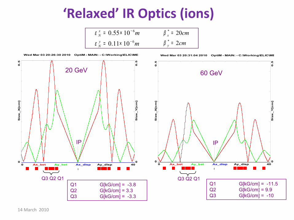
‘Relaxed’ IR Optics (ions)
2 1* *IR
f ff
ζβ β
=:
400
Wed Mar 03 20:04:34 2010 OptiM - MAIN: - C:\Working\ELIC\MEIC\Optics\IR\ion\p_7m_tri_LR_1.opt
300
00
50
BE
TA
_X
&Y
[m]
DIS
P_
X&
Y[m
]
BETA_X BETA_Y DISP_X DISP_Y
*
*
20
2x
y
cmcm
β
β
=
=
l * = 7m
IP
FF triplet
f
*3
*2 2
3
720 10
2.5 10ff mββ −≈ = ≈
××l
2*
*( )β ββ
= + ll
*( ) Nθ
εσγ β
=l
14 March 2010
6
6
0.55 10
0.11 10
xNyN
mm
ε
ε
−
−
= ×
= ×
‘Relaxed’ IR Optics (ions)*
*
20
2x
y
cm
cm
β
β
=
=
Q3 Q2 Q1
400
Wed Mar 03 20:26:30 2010 OptiM - MAIN: - C:\Working\ELIC\MEIC\Optics\IR\ion\p_7m_tri_LR_1_20GeV.opt
0.5
0
0.5
0
Siz
e_
X[c
m]
Siz
e_
Y[c
m]
Ax_bet Ay_bet Ax_disp Ay_disp
IP
400
Wed Mar 03 20:31:04 2010 OptiM - MAIN: - C:\Working\ELIC\MEIC\Optics\IR\ion\p_7m_tri_LR_1_20GeV.opt
0.5
0
0.5
0
Siz
e_
X[c
m]
Siz
e_
Y[c
m]
Ax_bet Ay_bet Ax_disp Ay_disp
Q3 Q2 Q1
IP
Q1 G[kG/cm] = -3.8Q2 G[kG/cm] = 3.3Q3 G[kG/cm] = -3.3
20 GeV 60 GeV
Q1 G[kG/cm] = -11.5Q2 G[kG/cm] = 9.9Q3 G[kG/cm] = -10

14 March 2010
‘Relaxed’ IR Optics (electrons)
2 1* *IR
f ff
ζβ β
=:
27.40
Wed Mar 03 22:39:42 2010 OptiM - MAIN: - C:\Working\ELIC\MEIC\Optics\IR\ele\e_350cm_LR_11GeV.opt
3000
0
50
BE
TA
_X
&Y
[m]
DIS
P_X
&Y
[m]
BETA_X BETA_Y DISP_X DISP_Y
*
*
5
0.5x
y
cmcm
β
β
=
=
l * = 3.5m
IP
FF doublets
f
*3
*2 2
3
3.55
20
.5 101
ff mββ − ×≈ = ≈
×l
2*
*( )β ββ
= + ll
*( ) Nθ
εσγ β
=l

14 March 2010
27.40
Wed Mar 03 23:06:03 2010 OptiM - MAIN: - C:\Working\ELIC\MEIC\Optics\IR\ele\e_350cm_LR_3GeV.opt
0.5
0
0.5
0
Siz
e_
X[c
m]
Siz
e_
Y[c
m]
Ax_bet Ay_bet Ax_disp Ay_disp27.40
Wed Mar 03 22:57:38 2010 OptiM - MAIN: - C:\Working\ELIC\MEIC\Optics\IR\ele\e_350cm_LR_11GeV.opt
0.5
0
0.5
0
Siz
e_
X[c
m]
Siz
e_
Y[c
m]
Ax_bet Ay_bet Ax_disp Ay_disp
6
6
85 10
17 10
xNyN
mm
ε
ε
−
−
= ×
= ×
‘Relaxed’ IR Optics (electrons)*
*
5
0.5x
y
cm
cm
β
β
=
=
IP
Q4 Q3 Q2 Q1
IP
3 GeV 11 GeV
Q1 G[kG/cm] = -5.5Q2 G[kG/cm] = 3.3Q3 G[kG/cm] = -5.1Q4 G[kG/cm] = 3.4
Q4 Q3 Q2 Q1 Q1 G[kG/cm] = -1.5Q2 G[kG/cm] = 0.9Q3 G[kG/cm] = -1.4Q4 G[kG/cm] = 0.9

14 March 2010
STAR
PHENIX
3 pass, 4 GeV ERL
MeRHIC
detector?
s = 1200 - 4000 GeV2
Electron energy: 2-4 GeV
Proton energy: up to 250 GeV
• MeRHIC– 1 (2 ?) detector(s)– Max Luminosity:
1032-1033 cm-2s-1
– 90% of hardware can be reused for eRHIC.
RHIC circumference: 3.8 km
MeRHIC@BNL (ERL-Ring) – an overview

14 March 2010
Max e/p Energies s Max Luminosity
ENC@GSI 3 x 15 180 Few x 1032
MEIC@JLab 11 x 60 250-2650 Few x 1034
MeRHIC@BNL 4 x 250 1200-4000 Close to 1033
ELIC@JLab 11 x 250 11000 Close to 1035
eRHIC@BNL 20 x 325 26000 Few x 1033
LHeC@CERN 70 x 1000 280000 1033
Design Goals for Colliders Under Consideration World-wide
Summary of current e-p/e-A collider ideas

12 November 2009 34
JLab CLAS12

14 March 2010
Kinematic coverage
x
Medium-energy EIC (JLab version)
s (CM energy)
Q2 ~ xys
• High-energy EIC (not shown)– Will move higher into the region covered by HERA (and LHeC)– Will provide good polarization and heavy ions (which HERA did not have)– If LHeC is not build, may be only machine that can see gluon saturation in e-A
collisions
-


