EIA & EMP for 100 MW Thermal Power Plant at...
37
DEEPAK PHENOLICS LTD ADDITION IN THE EXISTING PLANT AT DAHEJ GIDC ANNEXURE KADAM ENVIRONMENTAL CONSULTANTS | JANUARY 2017 30 3 ANNEXURES Annexure 1: Production Details S. No. Name of Product Production Capacity in MT/ Month Remarks As per EC received Addition Amendment Required 1 Phenol 16667 4723 21390 The design capacity and plant machinery will remain same. Amendment in capacities are considered based on full utilization of design capacities considering design margin. A communication from licensor confirming the proposed capacity utilization is attached as Figure 1. 2 Cumene 25000 2807 27807 3 Acetone 10000 2834 12834 4 Propane Return Stream 0 4367 4367 5 Alpha Methyl Styrene (AMS) 500 313 813 6 Benzene Rich Cut 175 -48 127 7 Recovery Column Bottoms / Heavies 730 1428 2158 8 Acetone Purge 0 17 17 9 Lights Hydrocarbon Purge 0 35 35 10 Poly- iso propyl Benzene (PIPB) Drag 0 88 88 11 Hydrogenation Products : Cyclohexanone, cyclohexanol, Methyl Iso- butyl Ketone (MIBK), Isopropyl Alcohol (IPA) 2650 14836 17486 12 Cyclohexanol Rich Stream 0 257 257 13 Acetone Rich Stream 0 289 289 14 Acetophenone 0 353 353 15 Wet IPA 0 250 250 Total 55722 32549 88271 16 Power (MW) 42 0 42 17 Steam (TPH) 100 100 200
Transcript of EIA & EMP for 100 MW Thermal Power Plant at...

DEEPAK PHENOLICS LTD ADDITION IN THE EXISTING PLANT AT
DAHEJ GIDC ANNEXURE
KADAM ENVIRONMENTAL CONSULTANTS | JANUARY 2017 30
3 ANNEXURES
Annexure 1: Production Details
S.
No. Name of Product
Production Capacity in MT/ Month
Remarks As per EC
received Addition
Amendment
Required
1 Phenol 16667 4723 21390 The design
capacity and
plant machinery
will remain
same.
Amendment in
capacities are
considered
based on full
utilization of
design
capacities
considering
design margin.
A
communication
from licensor
confirming the
proposed
capacity
utilization is
attached as
Figure 1.
2 Cumene 25000 2807 27807
3 Acetone 10000 2834 12834
4 Propane Return Stream 0 4367 4367
5 Alpha Methyl Styrene
(AMS) 500 313 813
6 Benzene Rich Cut 175 -48 127
7 Recovery Column Bottoms
/ Heavies 730 1428 2158
8 Acetone Purge 0 17 17
9 Lights Hydrocarbon Purge 0 35 35
10 Poly- iso propyl Benzene
(PIPB) Drag 0 88 88
11
Hydrogenation Products :
Cyclohexanone,
cyclohexanol, Methyl Iso-
butyl Ketone (MIBK),
Isopropyl Alcohol (IPA)
2650 14836 17486
12 Cyclohexanol Rich Stream 0 257 257
13 Acetone Rich Stream 0 289 289
14 Acetophenone 0 353 353
15 Wet IPA 0 250 250
Total 55722 32549 88271
16 Power (MW) 42 0 42
17 Steam (TPH) 100 100 200

DEEPAK PHENOLICS LTD ADDITION IN THE EXISTING PLANT AT
DAHEJ GIDC ANNEXURE
KADAM ENVIRONMENTAL CONSULTANTS | JANUARY 2017 31
Figure 1: Licensor’s Note on Proposed Capacity Utilization
DEEPAK PHENOLICS LTD ADDITION IN THE EXISTING PLANT AT
DAHEJ GIDC ANNEXURE
KADAM ENVIRONMENTAL CONSULTANTS | JANUARY 2017 32
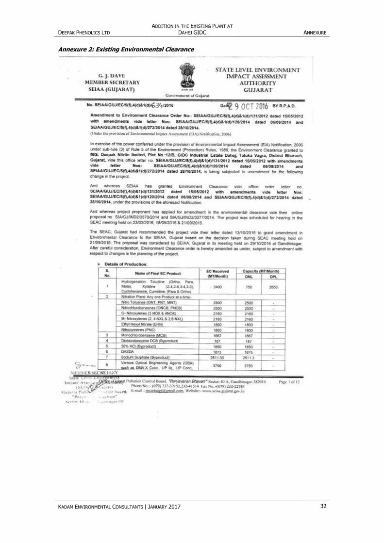
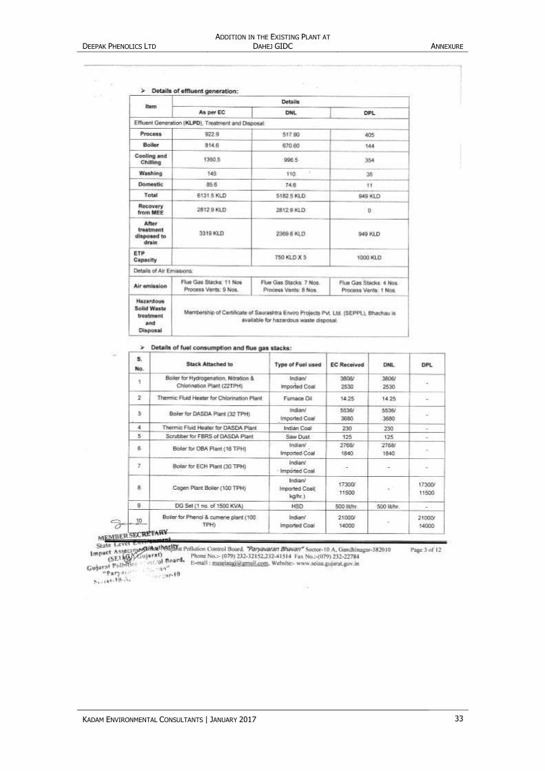
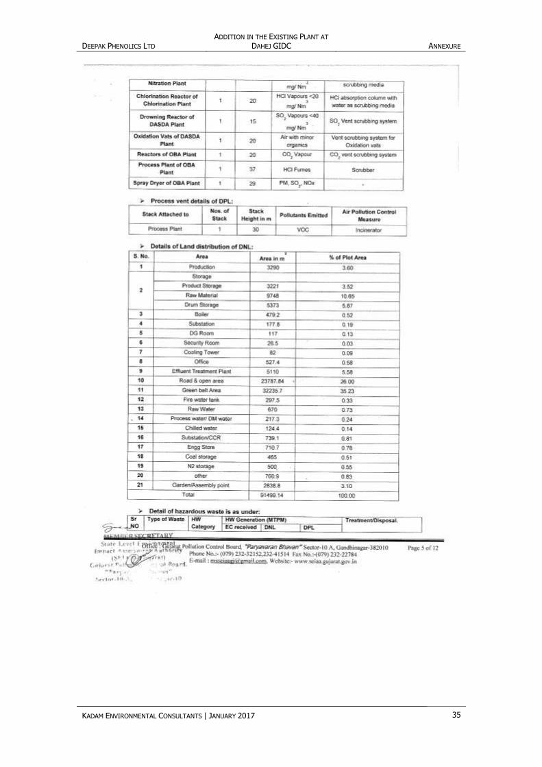
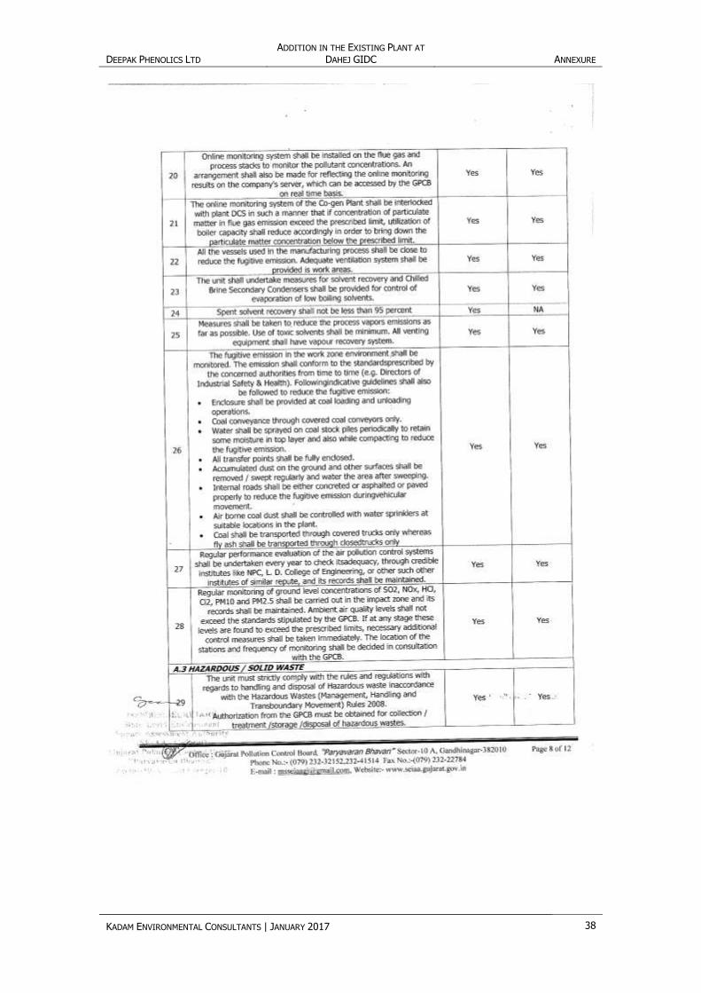
Annexure 2: Existing Environmental Clearance
DEEPAK PHENOLICS LTD ADDITION IN THE EXISTING PLANT AT
DAHEJ GIDC ANNEXURE
KADAM ENVIRONMENTAL CONSULTANTS | JANUARY 2017 33

DEEPAK PHENOLICS LTD ADDITION IN THE EXISTING PLANT AT
DAHEJ GIDC ANNEXURE
KADAM ENVIRONMENTAL CONSULTANTS | JANUARY 2017 34
DEEPAK PHENOLICS LTD ADDITION IN THE EXISTING PLANT AT
DAHEJ GIDC ANNEXURE
KADAM ENVIRONMENTAL CONSULTANTS | JANUARY 2017 35

DEEPAK PHENOLICS LTD ADDITION IN THE EXISTING PLANT AT
DAHEJ GIDC ANNEXURE
KADAM ENVIRONMENTAL CONSULTANTS | JANUARY 2017 36

DEEPAK PHENOLICS LTD ADDITION IN THE EXISTING PLANT AT
DAHEJ GIDC ANNEXURE
KADAM ENVIRONMENTAL CONSULTANTS | JANUARY 2017 37
DEEPAK PHENOLICS LTD ADDITION IN THE EXISTING PLANT AT
DAHEJ GIDC ANNEXURE
KADAM ENVIRONMENTAL CONSULTANTS | JANUARY 2017 38

DEEPAK PHENOLICS LTD ADDITION IN THE EXISTING PLANT AT
DAHEJ GIDC ANNEXURE
KADAM ENVIRONMENTAL CONSULTANTS | JANUARY 2017 39

DEEPAK PHENOLICS LTD ADDITION IN THE EXISTING PLANT AT
DAHEJ GIDC ANNEXURE
KADAM ENVIRONMENTAL CONSULTANTS | JANUARY 2017 40

DEEPAK PHENOLICS LTD ADDITION IN THE EXISTING PLANT AT
DAHEJ GIDC ANNEXURE
KADAM ENVIRONMENTAL CONSULTANTS | JANUARY 2017 41

DEEPAK PHENOLICS LTD ADDITION IN THE EXISTING PLANT AT
DAHEJ GIDC ANNEXURE
KADAM ENVIRONMENTAL CONSULTANTS | JANUARY 2017 42

DEEPAK PHENOLICS LTD ADDITION IN THE EXISTING PLANT AT
DAHEJ GIDC ANNEXURE
KADAM ENVIRONMENTAL CONSULTANTS | JANUARY 2017 43
Annexure 3: Details of Land Possession

DEEPAK PHENOLICS LTD ADDITION IN THE EXISTING PLANT AT
DAHEJ GIDC ANNEXURE
KADAM ENVIRONMENTAL CONSULTANTS | JANUARY 2017 44
DEEPAK PHENOLICS LTD ADDITION IN THE EXISTING PLANT AT
DAHEJ GIDC ANNEXURE
KADAM ENVIRONMENTAL CONSULTANTS | JANUARY 2017 45
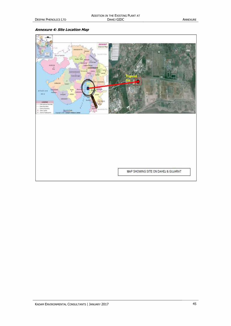
Annexure 4: Site Location Map

DEEPAK PHENOLICS LTD ADDITION IN THE EXISTING PLANT AT DAHEJ GIDC ANNEXURE
KADAM ENVIRONMENTAL CONSULTANTS | JANUARY 2017 46
Annexure 5: Site Layout Map
DEEPAK PHENOLICS LTD ADDITION IN THE EXISTING PLANT AT
DAHEJ GIDC ANNEXURE
KADAM ENVIRONMENTAL CONSULTANTS | JANUARY 2017 47
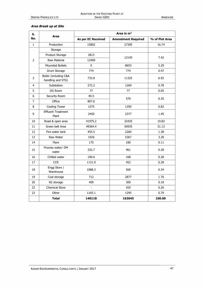
Area Break up at Site
S.
No. Area
Area in m2
As per EC Received Amendment Required % of Plot Area
1 Production 15802 27395 16.74
2
Storage
Product Storage 2813 12145 7.42
Raw Material 12409
Mounded Bullets 0 8653 5.29
Drum Storage 774 774 0.47
3 Boiler (including C&A
handling and STG) 733.8 11325 6.92
4 Substation 272.2 1269 0.78
5 DG Room 77 77 0.05
6 Security Room 40.5 570 0.35
7 Office 807.6
8 Cooling Tower 1575 1350 0.82
9 Effluent Treatment
Plant 2450 2377 1.45
10 Road & open area 41975.2 32435 19.82
11 Green belt Area 49364.4 50935 31.13
12 Fire water tank 455.5 2260 1.38
13 Raw Water 1026 5367 3.28
14 Flare 175 180 0.11
15 Process water/ DM
water 332.7 461 0.28
16 Chilled water 190.6 168 0.28
17 CCR 1131.9 452 0.28
18 Engg Store /
Warehouse 1088.3 560 0.34
19 Coal storage 712 2877 1.76
20 N2 storage 400 300 0.18
22 Chemical Store - 420 0.26
23 Other 1165.1 1295 0.79
Total 140118 163645 100.00
DEEPAK PHENOLICS LTD ADDITION IN THE EXISTING PLANT AT
DAHEJ GIDC ANNEXURE
KADAM ENVIRONMENTAL CONSULTANTS | JANUARY 2017 48
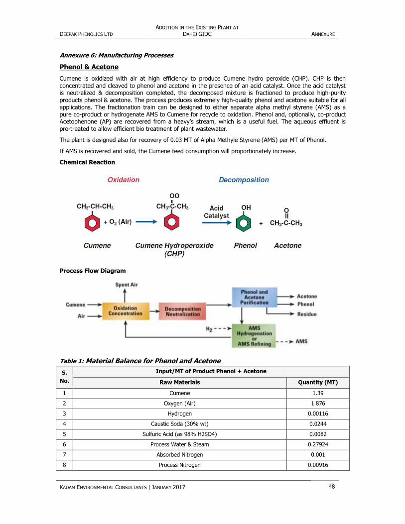
Annexure 6: Manufacturing Processes
Phenol & Acetone
Cumene is oxidized with air at high efficiency to produce Cumene hydro peroxide (CHP). CHP is then concentrated and cleaved to phenol and acetone in the presence of an acid catalyst. Once the acid catalyst is neutralized & decomposition completed, the decomposed mixture is fractioned to produce high-purity products phenol & acetone. The process produces extremely high-quality phenol and acetone suitable for all applications. The fractionation train can be designed to either separate alpha methyl styrene (AMS) as a pure co-product or hydrogenate AMS to Cumene for recycle to oxidation. Phenol and, optionally, co-product Acetophenone (AP) are recovered from a heavy’s stream, which is a useful fuel. The aqueous effluent is pre-treated to allow efficient bio treatment of plant wastewater.
The plant is designed also for recovery of 0.03 MT of Alpha Methyle Styrene (AMS) per MT of Phenol.
If AMS is recovered and sold, the Cumene feed consumption will proportionately increase.
Chemical Reaction
Process Flow Diagram
Table 1: Material Balance for Phenol and Acetone
S.
No.
Input/MT of Product Phenol + Acetone
Raw Materials Quantity (MT)
1 Cumene 1.39
2 Oxygen (Air) 1.876
3 Hydrogen 0.00116
4 Caustic Soda (30% wt) 0.0244
5 Sulfuric Acid (as 98% H2SO4) 0.0082
6 Process Water & Steam 0.27924
7 Absorbed Nitrogen 0.001
8 Process Nitrogen 0.00916

DEEPAK PHENOLICS LTD ADDITION IN THE EXISTING PLANT AT
DAHEJ GIDC ANNEXURE
KADAM ENVIRONMENTAL CONSULTANTS | JANUARY 2017 49
9 N2 Purge/ Diluents 0.003
10 Column Air Leak 0.003
11 Resin 0.0001
12 Activated Carbon 0.00007
13 MSHP Catalyst 0.00001
Total (Ton) 3.60
S.
No.
Output/MT of Product Phenol + Acetone
Remark Product
Liquid
Effluent
Air
Emission
Recovery/
Product
Solid
Waste
1 Phenol 1 Sale
2 Acetone 0.6090 Sale
3 Recovery column
bottoms/heavies 0.0776 sale
4 Alpha Methyl Styrene
(AMS) 0.0380 Sale
5 Acetone Purge 0.0008 Sale
6 Lights Hydrocarbon
Purge 0.0016 Sale
7 Waste Water 0.38 Sent to ETP
8 Spent Air 1.4920
Sent to
Incinerator
9 Spent Resin 0.0001 Sent to TSDF
10 Spent Carbon 0.00007 Sent to TSDF
11 Spent Catalyst 0.00001 Sent for metal
recovery
Total (Ton) 0.38 1.492 1.72703 0.00018 -
3.60
Cumene
Benzene is Alkylated with Propylene in the Alkylation reactor to produce Iso Propyl Benzene or Cumene.
Zeolite catalyst is used as the catalyst for the Alkylation reaction. Reaction takes place in liquid phase. Benzene and Propylene are fed to the reactor with a molar ratio of 2:1 Excess Benzene is recycled to the reactor through Benzene column .Di Iso Propyl Benzene (DIPB) and Tri Iso Propyl Benzene (TIPB) are also formed as side reaction products in the reactor. These are collectively called PIPB.
DIPB is formed by the reaction of Propylene with Cumene and TIPB is formed by the reaction of Propylene
with DIPB.
Both DIPB and TIPB are converted to Cumene in the Transalkylation reactor by reaction with Benzene.
Chemical Reaction

DEEPAK PHENOLICS LTD ADDITION IN THE EXISTING PLANT AT
DAHEJ GIDC ANNEXURE
KADAM ENVIRONMENTAL CONSULTANTS | JANUARY 2017 50
Process Flow Diagram
Table 2: Material Balance for Cumene
Input/MT of Product
S. No. Raw Materials Quantity (MT)
1 Propylene 0.510
2 Benzene 0.657
3 N2 purge for vacuum system 0.0005
4 Air Leak into system 0.00016
5 Adsorbent/ Clay 0.0005
6 Catalyst 0.000007
Total (Ton) 1.17
S.
No.
Output/MT of Product Cumene
Remark Product
Liquid
Effluent
Air
Emission
Recovery/
Product
Solid
Waste
1 Cumene 1 To be used as feed
for phenol plant.
2 Propane Return Stream 0.157 Sale
3 Benzene Rich Cut 0.00455 Sale
4 Poly- iso propyl Benzene
(PIPB) Drag 0.00326 Sale
5 Off gases 0.00233 Sent to Flare
6 Water 0.00092 Sent to ETP
7 Spent Adsorbent 0.0005 Sent to TSDF
8 Spent Catalyst 0.000007 Sent to TSDF
Total (Ton) 0.00092 0.00233 1.16481 0.000507 -
Total (Ton) 1.17 -
MIBK
Raw material: Acetone, Hydrogen
Process Description:

DEEPAK PHENOLICS LTD ADDITION IN THE EXISTING PLANT AT
DAHEJ GIDC ANNEXURE
KADAM ENVIRONMENTAL CONSULTANTS | JANUARY 2017 51
Methyl-Isobutyl-ketone (MIBK) is produced by reacting acetone and hydrogen over a palladium doped
resin catalyst in multi-tubular trickle bed reactor. The reaction effluent consisting MIBK product,
byproducts and unreacted reactants are further sent at DMK recovery section. The unconverted
acetone is recycled back to reaction section and crude MIBK stream is sent to MIBK purification
section. Pure MIBK product stream is drawn off as a side stream from the overhead section of the
distillation column while heavies are obtained as bottom product. Water phase from DMK recovery &
crude MIBK section is treated in water stripping and byproduct fractionation section to strip out all
hydrocarbons i.e. lights & thus obtaining a waste water stream adequate to be disposed off to battery
limit in order to be treated in a conventional waste water treatment system to match with any
environmental requirement.
Chemical Reaction
Process Flow Diagram
DEEPAK PHENOLICS LTD ADDITION IN THE EXISTING PLANT AT
DAHEJ GIDC ANNEXURE
KADAM ENVIRONMENTAL CONSULTANTS | JANUARY 2017 52
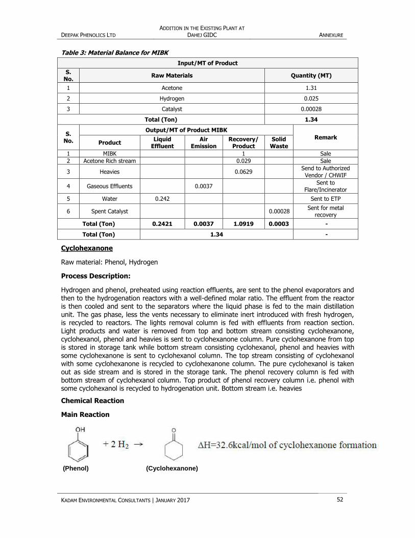
Table 3: Material Balance for MIBK
Input/MT of Product
S. No.
Raw Materials Quantity (MT)
1 Acetone 1.31
2 Hydrogen 0.025
3 Catalyst 0.00028
Total (Ton) 1.34
S. No.
Output/MT of Product MIBK
Remark Product
Liquid Effluent
Air Emission
Recovery/ Product
Solid Waste
1 MIBK 1 Sale
2 Acetone Rich stream 0.029 Sale
3 Heavies 0.0629 Send to Authorized Vendor / CHWIF
4 Gaseous Effluents
0.0037 Sent to
Flare/Incinerator
5 Water 0.242 Sent to ETP
6 Spent Catalyst
0.00028 Sent for metal
recovery
Total (Ton) 0.2421 0.0037 1.0919 0.0003 -
Total (Ton) 1.34 -
Cyclohexanone
Raw material: Phenol, Hydrogen
Process Description:
Hydrogen and phenol, preheated using reaction effluents, are sent to the phenol evaporators and
then to the hydrogenation reactors with a well-defined molar ratio. The effluent from the reactor is then cooled and sent to the separators where the liquid phase is fed to the main distillation
unit. The gas phase, less the vents necessary to eliminate inert introduced with fresh hydrogen, is recycled to reactors. The lights removal column is fed with effluents from reaction section.
Light products and water is removed from top and bottom stream consisting cyclohexanone,
cyclohexanol, phenol and heavies is sent to cyclohexanone column. Pure cyclohexanone from top is stored in storage tank while bottom stream consisting cyclohexanol, phenol and heavies with
some cyclohexanone is sent to cyclohexanol column. The top stream consisting of cyclohexanol with some cyclohexanone is recycled to cyclohexanone column. The pure cyclohexanol is taken
out as side stream and is stored in the storage tank. The phenol recovery column is fed with
bottom stream of cyclohexanol column. Top product of phenol recovery column i.e. phenol with some cyclohexanol is recycled to hydrogenation unit. Bottom stream i.e. heavies
Chemical Reaction
Main Reaction
(Phenol) (Cyclohexanone)

DEEPAK PHENOLICS LTD ADDITION IN THE EXISTING PLANT AT
DAHEJ GIDC ANNEXURE
KADAM ENVIRONMENTAL CONSULTANTS | JANUARY 2017 53
Side Reaction
Process Flow Diagram
Table 4: Material Balance for Cyclohexanone
Input/MT of Product
S. No. Raw Materials Quantity (MT)
1 Phenol 1.055
2 Hydrogen 0.05099
3 Catalyst 0.000074
Total (Ton) 1.1
S.
No.
Output/MT of Product Cyclohexanone
Remark Product
Liquid
Effluent
Air
Emission
Recovery/
Product
Solid
Waste
1 Cyclohexanone 1 Sale
2 Cyclohexanol 0.035 Sale

DEEPAK PHENOLICS LTD ADDITION IN THE EXISTING PLANT AT
DAHEJ GIDC ANNEXURE
KADAM ENVIRONMENTAL CONSULTANTS | JANUARY 2017 54
3 Heavies 0.024 Sale
4 Gaseous Effluents 0.0090 Sent to
Incinerator/Flare/Scrubber
5 Water 0.0712 Sent to ETP
6 Spent Catalyst
0.000074 Sent for metal recovery
Total (Ton) 0.0712 0.0090 1.059 0.000074 -
Total (Ton) 1.1 -
Isopropyl Alcohol
Raw material: Acetone, Hydrogen
Process Description:
The hydrogenation reactor operates in mixed phase, in trickle bed flow regime, and is operated at a
moderately high pressure. Higher pressures aid the hydrogenation reaction by increasing hydrogen
solubility in acetone. Acetone feedstock is mixed with the effluent recirculation. Hydrogen feedstock is
compressed to the required pressure using a two-stage reciprocating compressor. The combined
reactor feed is heated against the effluent and fed to the top of the reactor. A cooling water cooler
helps remove the heat of reaction from the effluent, which is then directed to a vapor/liquid separator
where unreacted hydrogen is recovered for recycle back to the reactor. An IPA Column recovers
commercial grade IPA from the hydrogenation reactor effluent, removing impurities such as water,
acetone, methanol etc. Hydrogenation reactor effluent flows to the IPA column. Wet IPA purge is
removed as distillate under reflux drum level control, and is routed to battery limits. IPA product is
recovered as bottoms liquid and it is cooled in a cooling water exchanger prior to being routed to
battery limits.
Chemical Reaction
Process Flow Diagram

DEEPAK PHENOLICS LTD ADDITION IN THE EXISTING PLANT AT
DAHEJ GIDC ANNEXURE
KADAM ENVIRONMENTAL CONSULTANTS | JANUARY 2017 55
Table 5: Material Balance for Isopropyl Alcohol
Input/MT of Product
S. No. Raw Materials Quantity (MT)
1 Acetone 0.9863
2 Catalyst 0.00012
3 Hydrogen 0.0348
Total (Ton) 1.02
S. No.
Output/MT of Product Isopropyl Alcohol
Remark Product
Liquid Effluent
Air Emission
Recovery/ Product
Solid Waste
1 Isopropyl Alcohol 1 Sale
2 Wet IPA 0.0208 Sale
3 IPA vapor vent 0.00373 Sent to Flare
4 Spent Catalyst 0.00012 Sent for metal recovery/ TSDF
Total (Ton) 0 0.00373 1.0208 0.00012 -
Total (Ton) 1.02 -
Acetophenone
Raw material: Recovery column bottoms/heavies, Sulfuric acid
Process Description:
Acetophenone (AP) is produced as a by-product in the oxidation and cleavage reactions of the phenol
process. The salts and sodium phenates is removed by washing with acid and steam condensate in a
wash drum. The aqueous phase from wash drum is purged to dephenolation feed tank in the phenol
plant. The washed heavies product is sent to distillation. In the AP heavies removal column, heavies
are removed from bottom as a purge and hydrocarbon exits as an overhead product. Water obtained
from the wash system is removed from reflux drum boot and from vent condenser to a drain. The
distillate from AP heavies removal column is further treated under atmospheric pressure in the AP
Light Stripping Column to remove phenol and other light components. This light stream is sent to light
storage tank in the phenol plant. The bottom product is sent to the next column for further treatment.
Dimethyl Benzyl Alcohol (DMBA) in the stream is close boiling to AP and thus is difficult to be
fractionated from AP. Therefore, it is removed in an AP Purification Reactor using acidic type catalyst.
This reactor takes feed from a total trap-out tray from AP Light Stripping Column and returns the
product to the tray below. Lights, water, and heavies are formed from the reaction. Water is removed
from the boot of reflux drum. The bottom stream of AP Lights removal column, containing
approximately 90% of AP, is further purified in the AP product column. AP product is withdrawn as a
side draw from a tray near top of the column. Bottom stream containing azeotrope of phenol/AP is
recycled back to AP Heavies Removal Column for recovery of AP.

DEEPAK PHENOLICS LTD ADDITION IN THE EXISTING PLANT AT
DAHEJ GIDC ANNEXURE
KADAM ENVIRONMENTAL CONSULTANTS | JANUARY 2017 56
Process Flow Diagram
Table 6: Material Balance for Acetophenone
Input/MT of Product
S.
No. Raw Materials Quantity (MT)
1 Recovery column bottoms/heavies 5.7
2 Sulfuric acid (98 %wt ) 0.1
3 Catalyst 0.00085
4 Steam condensate 0.8
Total (Ton) 6.60
S.
No.
Output/MT of Product Acetophenone
Remark Product
Liquid
Effluent
Air
Emission
Recovery/
Product
Solid
Waste
1 Acetophenone 1 sale
2 Heavies from
Acetophenone process 3.9 Send to
Authorized
Vendor / CHWIF 3 Lights from Aceto
phenone process 0.8
4 Aqueous purge 0.9 Sent to ETP
5 Spent Catalyst
0.00085 Sent to TSDF
Total (Ton) 0.9 0 5.7 0.00085 -
Total (Ton) 6.60 -

DEEPAK PHENOLICS LTD ADDITION IN THE EXISTING PLANT AT DAHEJ GIDC ANNEXURE
KADAM ENVIRONMENTAL CONSULTANTS | JANUARY 2017 57
Annexure 7: Raw Material & Product Storage Details
Table 7: Storage Details of Raw Material
S. No. Raw Materials /
Product State
Consumption,
MTPM
Mode of
Storage
Capacity of each
storage in m3
No. of
Tanks/Bullets
Total Capacity
(m3)
Storage Condition
Temp, °C Press, atm
As per EC received
1 Propylene Liquid 7916 Mounded Bullet 2100 4 8400 Atm. 18-22
2 Benzene Liquid 14666 Tank 2800 2 5600 Atm. Ambient
3 Caustic soda Lye Liquid 165 Tank 43 1 43 Atm. Ambient
4 Sulphuric acid 98% Liquid 206 Tank 34 1 34 Atm. Ambient
5 Hexamethylenamine
(Dytek or HMDA) Liquid 16 Tank 6 1 6 Atm. Ambient
6 Cumene Liquid 1316 Tank 50 3 150 Atm. Ambient
Amendment Required for
1 Propylene Liquid 14188 Mounded Bullet 4293 2 8586 Ambient 18-22
2 Benzene Liquid 18274 Tank 4023 2 8046 Ambient Atm.
3 Caustic soda Lye Liquid 347 Tank 127 1 127 Ambient Atm.
4 Sulphuric acid 98% Liquid 175 Tank 53 1 53 Ambient Atm.
5 HCl (30 wt%) Liquid 39 Tank 22 1 22 Ambient Atm.
6 Hydrogen (Through
pipeline Gaseous 578 Cylinder battery 0.270 MT 1 0.270 MT Ambient 100 bar
Table 8: Storage Details of Products
S.
No. Chemicals State
Consumption
(MT/Month)
Hazard
Involved
Means of
Storage
Operating Condition
(Storage) Capacity of
Vessel in
m3
No. of
Vessels
Storage
Capacity
(m3) Press Kg/Cm2 Temp ºC
As per EC received
1 Cumene Liquid 23000 Flammable Atm. storage tank Ambient Atm. 6872 3 20616
2 Phenol Liquid 16666 Toxic Atm. storage tank Ambient 50 5409 2 10818
3 Acetone Liquid 10000 Flammable Atm. storage tank Ambient Atm. 4523 2 9046
Amendment Required
1 Cumene Liquid 27807 Flammable Tank Atm. Ambient 8094 1 8094
2 Phenol Liquid 21390 Toxic Tank Ambient 55 4276 2 8552
3 Acetone Liquid 12834 Flammable Tank Atm. Ambient 3079 2 6158
4 Propane return stream Liquid 4367 Flammable Mounded Bullet 13.6 Ambient 2875 1 2875
5 Alpha Methyl Styrene
(AMS) Liquid 813 Flammable Tank Atm. Ambient 225 1 225
6 Benzene Rich Cut Liquid 127 Flammable Tank Atm. Ambient 40 1 40
7 Recovery Column Bottoms
/ Heavies Liquid 2158 Flammable Tank Atm. 95 456 1 456
8 Light Hydrocarbon Purge Liquid 35 Flammable Vessel Atm. 50 12 1 12
9 Acetone Purge Liquid 17 Flammable Vessel Atm. 5.4 6.2 1 6.2
10 Poly- iso propyl Benzene
(PIPB) Drag Liquid 88 Flammable Tank Atm. Ambient 26 1 26
11
Hydrogenation Products
Cyclohexanone Liquid 10695 Flammable Tank Ambient Atm. 992 2 1984
Cyxlohexanol Liquid 374 Flammable Tank Ambient Atm. 319 2 638
Methyl Iso-butyl Ketone Liquid 3209 Flammable Tank Ambient Atm. 518 2 1035
Isopropyl Alcohol Liquid 3209 Flammable Tank Ambient Atm. 518 2 1035
12 Cyclohexanol Rich Stream Liquid 257 Flammable Tank Ambient Atm. 83 1 83
13 Acetophenone Liquid 353 Flammable Tank Ambient Atm. 114 1 114
14 Acetone Rich Stream Liquid 289 Flammable Tank Ambient Atm. 93 1 93
15 Wet IPA Liquid 250 Flammable Tank Ambient Atm. 81 1 81

DEEPAK PHENOLICS LTD ADDITION IN THE EXISTING PLANT AT DAHEJ GIDC ANNEXURE
KADAM ENVIRONMENTAL CONSULTANTS | JANUARY 2017 58
Annexure 8: Water Consumption and Waste Water Generation Details
Water will be sourced from GIDC water supply. Total water consumption after proposed expansion
will be 9074 KLD from that 1260 KLD will be recycled water and 7814 KLD fresh water required.
Details are given in Table 9. Wastewater discharge to GIDC drain is not increasing from existing c
Table 9: Water Consumption Details
S. No. Description Water Consumption in KLD
As per EC Received Addition Amendment Required
1 Raw water to DM Plant 677 1047 1724
a Process 177 103 280
b Boiler 500 719 1219
2 Cooling & Chilling 1299 5979 7278
3 Washing 35 0 35
4 Domestic 12 0 12
5 Gardening 25 0 25
Total Gross 2048 7026 9074
6 Recycle water from RO 0 1260 1260
Total Fresh water
Consumption 2048 5766 7814
Table 10: Waste Water Generation Details
S.
No. Description
Waste water generation in KLD
Remarks As per EC
received Addition
Amendment
Required
1 Process 405 172 577
2 Boiler 144 -12 132
Not accounted as it
shall be used
internally for dust
suppression.
3 DM Regeneration 0 564 564
DM regeneration,
Condensate Polishing
& PSF back washes
4 Cooling & Chilling 354 654 1008
5 Washing 35 13 48
6 Domestic 10 2 12
Total Water to ETP 949 1260 2209
8 Recycle water
from RO 0 1260 1260
Final discharge to
GIDC drain 949 0 949

DEEPAK PHENOLICS LTD ADDITION IN THE EXISTING PLANT AT
DAHEJ GIDC ANNEXURE
KADAM ENVIRONMENTAL CONSULTANTS | JANUARY 2017 59
Annexure 9: Details of ETP
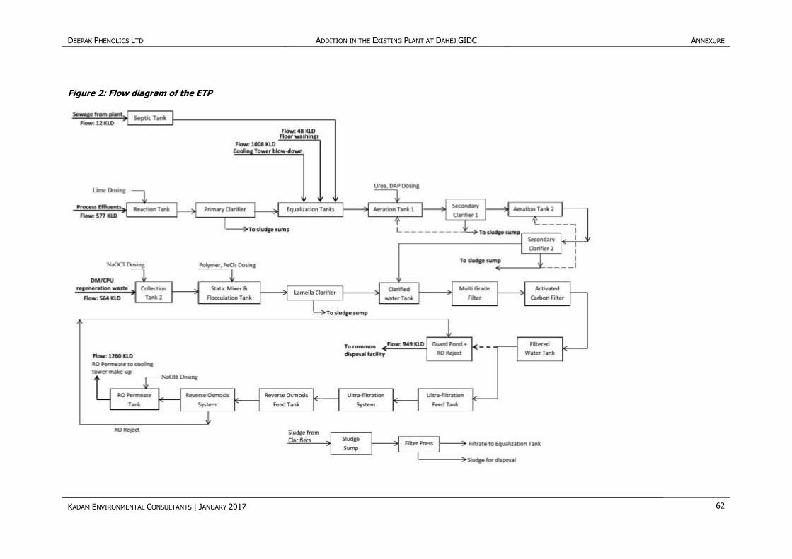
The Effluent Treatment Unit is basically a bio-treatment system consisting of an equalization tank,
aeration basins and clarifiers to reduce the BOD, COD and the phenol contents to the acceptable
levels before discharging it to common GIDC facility.
Also, a recycle system post ETP is considered to meet the discharge limit requirements and to
optimize the fresh water intake.
Since the process effluents have a high COD/BOD ratio, provision of dilution with cooling tower
blow-down or DM/CPU regeneration waste is there for meeting the bio-treatability requirements.
Primary Treatment
The process effluent is led to the reaction tank where lime dosing is done to increase the pH from
5.5 to 7-8. Addition of lime results in the formation of sludge which is removed in the primary
clarifier. The sludge formed due to lime is settled at the bottom of the primary clarifier which will
be separated and pumped to the sludge sump. The clarified effluent flows to the equalization tank.
The oil bearing streams from the plant will be pumped to the Oil Trap Tank to separate the free oil
following which it is mixed with other streams in the equalization tank.
Two Equalization Tanks are provided which operate on a fill and draw principle. Part flow of the
cooling tower blow-down or DM-CPU regeneration waste is directed to the Equalization Tank to
dilute the process effluent for reducing the TDS to ~ 12000 ppm for the sake of bio-treatability.
Secondary Treatment
The Equalized effluent is transferred to Extended Aeration Tanks system for biological treatment
where the organic matter is degraded aerobically by the microbes. It’s a two stage Extended
Aeration Process working in series. The equalized effluent is introduced into the Extended Aeration
Tank-1 where aerobic bacterial culture is maintained in suspension in the form of bio-sludge. The
reactor contents are referred to as mixed liquor. In the reactor the bacterial culture carries out the
conversion as:
COHNS + O2 + NUTRIENTS CO2 + NH3 + C5H7NO2 + Degraded Colour
C5H7NO2 + 5O2 5CO2 + 2H2O + NH3 + energy
Diffused aeration system is used for providing the desired oxygen to microbes which also serves to
maintain the reactor contents in a completely mixed regime & Dissolve Oxygen (DO) level of 2
ppm. At the end of the aeration period the wastewater biological mass mixture (mixed liquor)
reaches the effluent end of the chamber and flows in a trough to the Secondary Clarifier-1 for the
separation of sludge and liquid. In order to ensure required population of bacteria in extended
aeration System, i.e., Mixed Liquor Suspended Solids (MLSS) and also Food to Micro-organisms
ratio (F/M), part of the settled sludge from the Secondary Clarifier-1 is re-circulated back to
Extended Aeration tank-1 while the liquid effluent overflows over weir into Extended Aeration
System II.
Here, further reduction in BOD takes place as per the mechanism described above.
A part of the separated solids is returned to the Extended Aeration tank-II as return sludge while
the liquid overflows over weir into Collection Tank-II where other streams like cooling tower blow-
down and DM-CPU regeneration waste are mixed with it.
Tertiary Treatment
The Mixed Liquor from Collection Tank II enters the Lamella Clarifier for separation of sludge and
liquid via SMFT (Static Mixer and Flocculation Tank). Flocculant and Coagulant is added in SMFT.
The main purpose of this tank is to mix the FeCl3 and Polymer with the effluent so that flocs will

DEEPAK PHENOLICS LTD ADDITION IN THE EXISTING PLANT AT
DAHEJ GIDC ANNEXURE
KADAM ENVIRONMENTAL CONSULTANTS | JANUARY 2017 60
be formed in Lamella Clarifier which will help in settling suspended solids. The clarified water from
the lamella clarifier is taken to the clarified water tank which also acts as a chlorine contact tank.
Here hypochlorite dosing is done to further reduce the BOD for preventing bio-fouling in
downstream filters.
The effluent from clarified water tank is pumped into Multi Grade filter (MGF) for the reduction of
suspended solids & turbidity before taking the effluent to downstream membrane systems. This
unit works on the phenomenon of surface filtration. At a pre-determined pressure drop the
backwash of filter is initiated to clean the filter bed. Backwash cycle can also be manually initiated.
The effluent from Multi Grade filter is the fed to Activated Carbon filter (ACF) to ensure reduction
in excess chlorine, colour, residual recalcitrant & organics. Activated carbon is a porous material,
mainly consisting of elementary carbon in a graphite-like structure. The internal surface area
typically amounts to 500 up to 1500 m2/g.
Treated water from ACF will be collected in filtered water tank which will act as collection tank,
from where one stream will go to Guard Pond + RO Reject Tank and the other stream will go to
for processing in the UF-RO system.
Ultra Filtration system: Ultra-filtration is a low pressure membrane process for the removal of
colloidal silica and colloidal particles (measured in terms of Silt Density Index). The feed water
flows from the inside of the fibres, permeates through the membrane and is removed as the
product from the shell side.
In Ultra-filtration, small molecules such as water, monosaccharide, simple alcohol and all ionic
species pass through the membrane while larger molecules, colloidal particulate matter and
bacteria are retained.
Ultra-filtration is the best pre-treatment technique for cost effective performance of the Reverse
Osmosis System as it leads to increased RO membranes life and reduced cleaning frequency. This
ultimately reduces the operating expenditure incurred on the RO system.
The treated water from Ultra-filtration system will be collected in the RO feed tank for temporary
storage & the treated water will be transferred to Reverse Osmosis System through pump for
further treatment as well as will be used during cleaning of Ultra-filtration system.
Reverse Osmosis System
The treated water from the RO feed tank is subjected to sodium Bi-sulphite (SBS) and Antiscalant
dosing prior to feeding in the cartridge filter. The Antiscalant Dosing System is provided to prevent
precipitation of sparingly soluble salts and hence to inhibit scale formation on RO membranes.
The SBS (sodium bisulphite) Dosing System is provided to remove traces of chlorine present in
raw water to protect the membranes. Also provision of shock dosing of SBS is made in case of any
excess free chlorine coming in to safe guard RO membranes. The RO unit comprises of cartridge
filters & high pressure pump.
Cartridge Filters are used to further reduce suspended solids to a level acceptable to the
downstream
Reverse Osmosis Membranes
High pressure pumps are used to feed the Reverse Osmosis skid which is an integrated assembly
of high-strength thermally cured fibre glass reinforced epoxy pressure tubes housing the RO
membrane elements, feed, product and concentrate piping, all mounted on a high-strength steel
structure. The skid comprises of two trains having a total of 108 modules. The operation of each
RO train shall be semi-automatic with a provision for membrane cleaning by chemical re-
circulation if the pressure drop across the system exceeds a pre-set value.

DEEPAK PHENOLICS LTD ADDITION IN THE EXISTING PLANT AT
DAHEJ GIDC ANNEXURE
KADAM ENVIRONMENTAL CONSULTANTS | JANUARY 2017 61
The RO is designed for 70% recovery and will be PLC operated. The RO reject is sent to the Guard
Pond + RO Reject Tank from where it will be pumped to GIDC common treatment facility. The RO
permeate or the recovered water will be recycled back for internal usage.
Sludge Treatment
Sludge from Lamella Clarifier, primary clarifier, Secondary Clarifier I and II shall be collected in
sludge sump and pumped to Filter Press for further treatment. The filtrate from the Filter Press is
sent back the Equalization Tank while the sludge cake formed will be disposed of as landfill.
Additionally sludge drying beds are provided for drying the sludge cake formed from the Filter
Press.
Table 11: Sizing of the Unit
S.
No.
Unit
No. Name of the Unit No.
Inside size (m)
x SWD (m)/
Inside size (m)
x Height (m)
Dimensions
(L x B x H)
(m x m x m)
Total
Capacity
(m3)
1 T-02 Reaction Tank - 1 1 - 2.75 x 2.75 x
2.0 15
2 N-01 Primary Clarifier 1 4 x 3 - 113
3 T-
03/04 Equalization Tank 2 - 9.2 x 8.7 x 5.0 800
4 T-01 Collection Tank - 1
with Oil Trap 1 - 2.0 x 1.9 x 2.5 10
5 T-05 Extended Aeration
Tank - 1 1 -
25.9 x 18.0 x
6.0 2830
6 N-02 Secondary Clarifier - 1 1 11 x 3.5 - 332
7 T-06 Extended Aeration
Tank - 2 1 - 18.0 x 8.2 x 6.0 890
8 N-03 Secondary Clarifier - 2 1 11 x 3.5 - 332
9 T-07 Collection Tank - 2 1 - 5.8 x 3.0 x 3.5 33
10 N-04 Lamella Clarifier 1 - - 331
11 T-08 SMFT 1 - - 32
12 T-09 Clarified Water Tank 1 - 9.7 x 3.3 x 3.5 113
13 F-01
A/B Multi Grade Filter 2 2.6 x 1.875 - 20
14 F-02
A/B Activated Carbon Filter 2 2.8 x 2.5 - 31
15 T-10 Filtered Water Tank 1 3.2 x 3.0 - 24
16 T-11 Guard Pond + RO
Reject Tank 1 - 13 x 3.0 x 4.0 156
17 T-12 UF Feed Tank 1 - 6.0 x 5.0 x 3.8 114
18 T-13 RO Feed Tank 1 - 6.5 x 5.0 x 2.5 85
19 T-15 RO Permeate Tank 1 - 9.0 x 9.0 x 3.0 243
20 T-16 Sludge Sump 1 - 3.0 x 1.5 x 4.5 10
21 T-17 Sludge Drying Bed - 1 1 - 13 x 6.5 x 1.0 85
22 T-18 Sludge Drying Bed - 2 1 - 13 x 6.5 x 1.0 85
DEEPAK PHENOLICS LTD ADDITION IN THE EXISTING PLANT AT DAHEJ GIDC ANNEXURE
KADAM ENVIRONMENTAL CONSULTANTS | JANUARY 2017 62
Figure 2: Flow diagram of the ETP

DEEPAK PHENOLICS LTD ADDITION IN THE EXISTING PLANT AT DAHEJ GIDC ANNEXURE
KADAM ENVIRONMENTAL CONSULTANTS | JANUARY 2017 63
Annexure 10: Fuel Consumption
Table 12: Fuel Consumption
S.
No. Stack Attached to Capacity
Stack
Nos.
Stack
Height Type of Fuel used
Fuel consumption
(Kg/hr.)
Air Pollution Control
Measures
As per EC received
1 Cogen Plant Boiler 100 TPH 1 81 Indian/Imported Coal 17300/11500 ESP & Adequate Stack Height
2 Boiler for phenol &
Cumene 100 TPH 1 81 Indian/Imported Coal 21000/14000
ESP with adequate stack
height will be provided
3 Incinerator for 304
Nm3/hr. Vent gas 304 Nm3/hr. 1 30 Gas 25 m3/ hr.
Adequate Stack Height will be
provided
4 DG Set (1 no.) 1500 KVA 1 25 HSD 500 lit/hr. Adequate Stack Height will be
provided
Amendment Required for
1 Boiler-1 100 TPH 1 81
Indian/Imported Coal/
Imported Coal+ Lignite
46000/42000/
16000+38000 ESP & Adequate Stack Height
2 Boiler-2 100 TPH
3 Incinerator 36440 Nm3/hr. 1 30 Gas 29 Adequate Stack Height will be
provided
4 DG Set 1500 KVA 1 30 HSD 500 lit/hr. Adequate Stack Height will be
provided
5 DG Set 1500 KVA 1 30 HSD 500 lit/hr. Adequate Stack Height will be
provided
DG Sets will be used only during Power failure.

DEEPAK PHENOLICS LTD ADDITION IN THE EXISTING PLANT AT DAHEJ GIDC ANNEXURE
KADAM ENVIRONMENTAL CONSULTANTS | JANUARY 2017 64
Annexure 11: Hazardous Waste Generation
Table 13: Hazardous Waste Generation and Disposal
S. No. Type of Waste Hazardous
Waste Category
Waste Quantity in MTPA
Treatment / Disposal As per EC received Addition
Amendment Required
1 ETP Sludge 34.3 3120 -2553 567 Collection, Storage, Transportation and Disposal at
TSDF site. Salt Sale/ TSDF Site
2 Used Oil 5.1 3000 0 3000 L Collection, storage, Transportation & Disposal by
selling to Registered Re-processor
3 Boiler Ash 36.2 48396 100782 149178 Collection, storage, Transportation & Disposal by selling to brick manufacturer or cement industry
4 Spent Carbon 35.3 66 -50 16 Collection, Storage, Transportation and Disposal at
TSDF site.
5 Discarded Container/
bags 33.3 240000 0 240000
Collection, decontamination, storage, transportation & sell to registered vendor
6 Spent Resin 19.1 0 9 9 Collection, Storage, Transportation and Disposal at
TSDF site.
8 Spent Catalyst 35.2 0 18 18 Collection, Storage, Transportation and Disposal at
TSDF site.
9 Spent Adsorbent 35.1 0 145 145 Collection, Storage, Transportation and Disposal at
TSDF site.
10 Heavies from MIBK
plant H 3 0 2424 2424 Send to Authorized Vendor / CHWIF
11 Heavies from
Acetophenone plant H 3 0 50 50 Send to Authorized Vendor / CHWIF
12 Lights from
Acetophenone plant H 3 0 10 10 Send to Authorized Vendor / CHWIF
13 Spent resin from
DM/CPU 34.2 0 7 7
Collection, Storage, Transportation and Disposal at TSDF site.
14 Spent carbon from
DM/CPU/ETP A-4160 0 25 25
Collection, Storage, Transportation and Disposal at TSDF site.
DEEPAK PHENOLICS LTD ADDITION IN THE EXISTING PLANT AT
DAHEJ GIDC ANNEXURE
KADAM ENVIRONMENTAL CONSULTANTS | JANUARY 2017 65
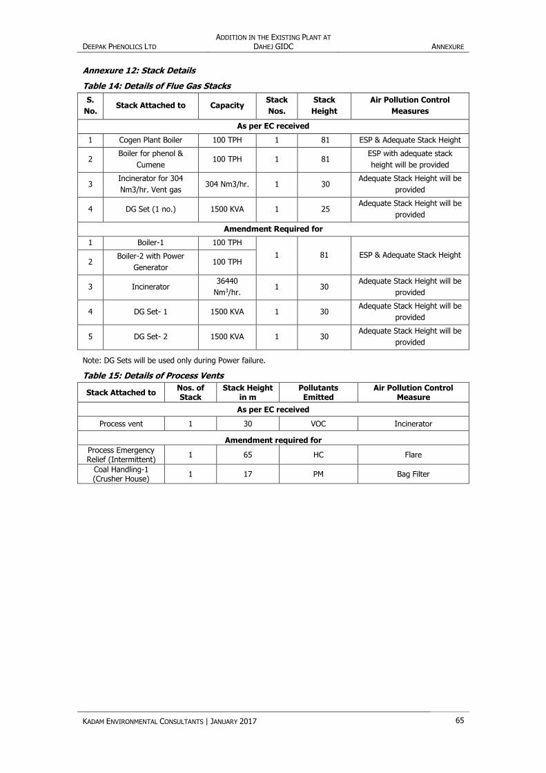
Annexure 12: Stack Details
Table 14: Details of Flue Gas Stacks
S.
No. Stack Attached to Capacity
Stack
Nos.
Stack
Height
Air Pollution Control
Measures
As per EC received
1 Cogen Plant Boiler 100 TPH 1 81 ESP & Adequate Stack Height
2 Boiler for phenol &
Cumene 100 TPH 1 81
ESP with adequate stack
height will be provided
3 Incinerator for 304
Nm3/hr. Vent gas 304 Nm3/hr. 1 30
Adequate Stack Height will be
provided
4 DG Set (1 no.) 1500 KVA 1 25 Adequate Stack Height will be
provided
Amendment Required for
1 Boiler-1 100 TPH
1 81 ESP & Adequate Stack Height 2
Boiler-2 with Power
Generator 100 TPH
3 Incinerator 36440
Nm3/hr. 1 30
Adequate Stack Height will be
provided
4 DG Set- 1 1500 KVA 1 30 Adequate Stack Height will be
provided
5 DG Set- 2 1500 KVA 1 30 Adequate Stack Height will be
provided
Note: DG Sets will be used only during Power failure.
Table 15: Details of Process Vents
Stack Attached to Nos. of Stack
Stack Height in m
Pollutants Emitted
Air Pollution Control Measure
As per EC received
Process vent 1 30 VOC Incinerator
Amendment required for
Process Emergency Relief (Intermittent)
1 65 HC Flare
Coal Handling-1 (Crusher House)
1 17 PM Bag Filter

CONTACT DETAILS
Vadodara (Head Office)
871/B/3, GIDC Makarpura, Vadodara, India – 390 010.
E: [email protected]; T:+91-265-3001000; F: +91-265-3001069
Delhi / NCR
Spaze IT Park, Unit No. 1124, 11th Floor, Tower B-3, Sector 49, Sohna Road, Gurgaon, India – 122 002
E: [email protected]; T/F : 0124-424 2430-436
Kadam Environmental Consultants w w w . ka d a m en v i r o . c o m
Envi ronment for Deve lopment