Egon+ board Loop S
2
For product manuals, technical specifications, certificates and declarations refer to the product website: This product complies with: • CE under EMC Directive 2014/30/EU • the requirements of level 2 devices of the Radio communications (Electromagnetic Compatibility) standard 2017 *988-12395-003* Loop S Dimensional drawings Compliance statements Technical specifications Egon+ board INSTALLATION GUIDE Environmental Operating temperature -40°C to 85°C Storage temperature -40°C to 125°C Mechanical shock SAE J2030 (RDEC2002), Section 6.16 Bombardment test 24 hour of dust, sand and gravel Salt fog 96 hour period of salt fog per ASTM B117-94 Protection class IP 66 Vibration SAE J1455 (R2006), Section 4.10.4.2 Chemical resistance Break fluid, AT fluid, antifreeze fluid, windshield wash fluid, PS fluid and oil. Abnormal conditions Revers polarity protection - 24 V DC, SAE J1455 (RJUN2006) - duration of 5 minutes Short circuit protection Short to ground 5 minutes, ER455 (R2008) Section 5.10.4 Short to 16 V DC 5 minutes, ER455 (R2008) Section 5.10.4 Power up operation Ramp battery voltage from 0 to min. operating voltage at 1 V/ms, EP455 (R2008) Section 5.10.7 Electrical Power supply voltage 12 V DC (8-16 V DC) Dielectric voltage withstanding 80 V DC Current consumption 1.5 mA battery quiescent current Total current limit 200 A Total current limit per connector 100 A Overload 135% Temperature rise 60°C Insulation resistance 10 MOhm Max load Fuse channels 30 A at 12 V DC Relay and fuse channels 20 A (resistive load)/16 A (inductive, motor, pump load) at 12 V DC Maximum board load 200 A Power connector 2x M8 input studs, each rated at 100 A maximum Power wire size Calculated based on total board consumption Output wire size 1.31 mm² - 5.26 mm² (#10-16 AWG) Fuses Mini blade fuse Relays 280 footprint, 4 pin relay Egon+ board 89.2 mm (3.51”) 120.5 mm (4.74”) 38.6 mm (1.51”) 108.2 mm (4.25”) 155.7 mm (6.12”) 29.5 mm (1.16”) 12.8 mm (0.50”) Warning: The user is cautioned that any changes or modifications not expressly approved by the party responsible for compliance could void the user’s authority to operate the equipment. Warning: IGNITION PROTECTED ONLY WHEN EQUIPPED WITH IGNITION PROTECTED FUSES AND COVER CLOSED. ANY REPLACEMENT FUSES MUST BE IGNITION PROTECTED. COVER MUST BE CLOSED IN EVERY OPERATIONAL CONDITION! AT30 Operating temperature -25°C to 65°C Power supply voltage 8-16 V DC NMEA 2000 current consumption 1 LEN CE EN 60945 www.lowrance.com www.bandg.com www.simrad-yachting.com
Transcript of Egon+ board Loop S
For product manuals, technical specifications, certificates and
declarations refer to the product website:
This product complies with:• CE under EMC Directive 2014/30/EU • the requirements of level 2 devices of the Radio
communications (Electromagnetic Compatibility) standard 2017
*988-12395-003*
Loop S
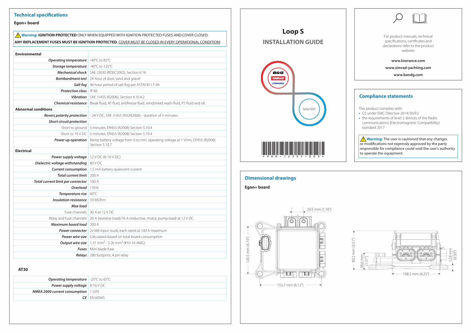
Dimensional drawings
Compliance statements
Technical specificationsEgon+ board
INSTALLATION GUIDE
Environmental
Operating temperature -40°C to 85°C
Storage temperature -40°C to 125°C
Mechanical shock SAE J2030 (RDEC2002), Section 6.16
Bombardment test 24 hour of dust, sand and gravel
Salt fog 96 hour period of salt fog per ASTM B117-94
Protection class IP 66
Vibration SAE J1455 (R2006), Section 4.10.4.2
Chemical resistance Break fluid, AT fluid, antifreeze fluid, windshield wash fluid, PS fluid and oil.
Abnormal conditions
Revers polarity protection - 24 V DC, SAE J1455 (RJUN2006) - duration of 5 minutes
Short circuit protection
Short to ground 5 minutes, ER455 (R2008) Section 5.10.4
Short to 16 V DC 5 minutes, ER455 (R2008) Section 5.10.4
Power up operation Ramp battery voltage from 0 to min. operating voltage at 1 V/ms, EP455 (R2008) Section 5.10.7
Electrical
Power supply voltage 12 V DC (8-16 V DC)
Dielectric voltage withstanding 80 V DC
Current consumption 1.5 mA battery quiescent current
Total current limit 200 A
Total current limit per connector 100 A
Overload 135%
Temperature rise 60°C
Insulation resistance 10 MOhm
Max load
Fuse channels 30 A at 12 V DC
Relay and fuse channels 20 A (resistive load)/16 A (inductive, motor, pump load) at 12 V DC
Maximum board load 200 A
Power connector 2x M8 input studs, each rated at 100 A maximum
Power wire size Calculated based on total board consumption
Output wire size 1.31 mm² - 5.26 mm² (#10-16 AWG)
Fuses Mini blade fuse
Relays 280 footprint, 4 pin relay
Egon+ board
89.2
mm
(3.5
1”)
120.
5 m
m (4
.74”
)
38.6
mm
(1.5
1”)
108.2 mm (4.25”)
155.7 mm (6.12”)
29.5 mm (1.16”)
12.8
mm
(0.5
0”)
Warning: The user is cautioned that any changes or modifications not expressly approved by the party responsible for compliance could void the user’s authority to operate the equipment.
Warning: IGNITION PROTECTED ONLY WHEN EQUIPPED WITH IGNITION PROTECTED FUSES AND COVER CLOSED.
ANY REPLACEMENT FUSES MUST BE IGNITION PROTECTED. COVER MUST BE CLOSED IN EVERY OPERATIONAL CONDITION!
AT30
Operating temperature -25°C to 65°C
Power supply voltage 8-16 V DC
NMEA 2000 current consumption 1 LEN
CE EN 60945
www.lowrance.com
www.bandg.com
www.simrad-yachting.com

F1 F2 F3 F4 F5 F6 F7 F8
R1 R2 R3 R4
R5 R6
R7 R8
F9 F10
F11
F12
F13
F14
F15
F16
F1
R1
1C
4A
F3
R2
1B
4F
F5
R3
1A
4E
F7
R4
3A
4D
F2
R5
1D
3H
F9
R6
1G
3G
+12 V DC
B
C
D
A
F13
R7
1E
4H
F14
R8
1H
2E
F4
4G
F6
4C
F8
4B
F10
2C
F11
2B
F12
2A
F15
2G
F16
2HE
CAN
F
OU
T. 1
OU
T. 2
OU
T. 3
OU
T. 4
OU
T. 5
OU
T. 6
OU
T. 7
OU
T. 8
OU
T. 9
OU
T. 1
0O
UT.
11
OU
T. 1
2
OU
T. 1
3O
UT.
14
OU
T. 1
5O
UT.
16
A. Main power inputB. FusesC. Relays D. Override pins for relay outputsE. Output pins for relays and fusesF. Output number
System overview
A. AT30 protocol converter (NMEA 2000 to Naviop CAN)B. Naviop CAN backboneC. TerminatorsD. Egon+ drop-cable CAN ID:1E. Egon+ drop-cable CAN ID:2 (only available for Loop S+)F. Egon+ boards (maximum 2 Egon+ boards can be installed)G. T-connectorsH. NMEA2000 backboneI. MFD
F
F
A
C C
H
B
D
E
H
I
G
12 V
12 V
12 V
Mounting guidelinesPower wiring
Wiring
Egon+ power input Egon+ electronic power supply
12 V DC
A DC
12 V DC
2 A
B
A. Power input cable (the cable must be able to carry the maximum current of all loads)B. Egon+ drop-cableC. Overcurrent protection (fuse or circuit breaker)D. M8 ring terminal (not included in the box)
Output connectors
1D 1C 1B 1A
1E 1G 1H
2C 2B 2A
2E 2G 2H
3A
3G 3H
4D 4C 4B 4A
4E 4F 4G 4H
Output 1 (black) Output 2 (gray) Output 3 (blue) Output 4 (green)
1A - bypass for relay R3 2A - output fuse F12 3A - bypass for relay R4 4A - output relay R1 (fuse F1)
1B - bypass for relay R2 2B - output fuse F11 - 4B - output fuse F8
1C - bypass for relay R1 2C - output fuse F10 - 4C - output fuse F6
1D - bypass for relay R5 - - 4D - output relay R4 (fuse F7)
1E - bypass for relay R7 2E - output relay R8 (fuse F14) - 4E - output relay R3 (fuse F5)
- - - 4F - output relay R2 (fuse F3)
1G - bypass for relay R6 2G - output fuse F15 3G - Output relay R6 (fuse F9) 4G - output fuse F4
1H - bypass for relay R8 2H - output fuse F16 3H - Output relay R5 (fuse F2) 4H - output relay R7 (fuse F13)
Bypassing a relayThe bypass is an override and it cannot be used as a parallel control. By connecting the bypass pin of a relay to DC negative the relay is closed and the output activated. The main important appliances (bilge pumps, navigation lights, blower, horn etc) must be equipped with a bypass for the safety of the boat.
Output connector wiringThe electrical wiring, connections and installation shall be in accordance with the requirements of ISO10133, ABYC E-11, AC and DC electrical system on boats. The wire size should be calculated based on the channels total load and the cable length. For bypass wires a #16 AWG cable is sufficient.A proper crimping tool for barrel open terminals should be used to crimp the cables to the wire terminals. Always use a fuse that is appropriate for the connected load. The fuses supplied may have to be replaced to match the outputs connected load.
BC
DEF
A A. WireB. Wire sealC. Wire terminal (female)D. Connector bodyE. Connector sealF. Assembled connector
System configuration
Before the Loop system can be operated from the MFD, it has to be configured. The web based Loop SetApp is used togenerate the configuration files and can be downloaded from one of the 3 brand websites: www.lowrance.com, www.bandg.com,www.simrad-yachting.com
Warning: The Loop system must only be configured by a competent installer. If your Loop system has not been pre-configured for you, please contact your dealer for advice on how to have the Loop system configured by a competent installer.
System IDs
System Egon + boards
Controlable outputs
Monitored power outputs
Drop-cable ID
Loop S 1 8 8 CAN ID:1
Loop S+ 2 16 16CAN ID:1 CAN ID:2
Egon+ boardThe recommended mounting orientation for the Egon+ board is horizontal (A). If horizontal mounting is not possible, it is recommended that device is mounted at an angle of 0-90° from horizontal (B). It is NOT recommended to mount the device at an angle greater than 90° from horizontal (C) due to drainage issues.
AT30 protocol converterCheck the labels on the AT30 protocol converter cable to ensure the correct connectors are attached to the NMEA 2000 network and to the Naviop CAN network.
A B C
Warning: IGNITION PROTECTED ONLY WHEN EQUIPPED WITH IGNITION PROTECTED FUSES AND COVER CLOSED. ANY REPLACEMENT FUSES MUST BE IGNITION PROTECTED. COVER MUST BE CLOSED IN EVERY OPERATIONAL CONDITION!