Efficient mode transformations of degenerate Laguerre ... · Efficient mode transformations of...
7
Efficient mode transformations of degenerate Laguerre–Gaussian beams Galina Machavariani, Amiel A. Ishaaya, Liran Shimshi, Nir Davidson, Asher A. Friesem, and Erez Hasman We present an approach for efficient conversion of a single-high-order-mode distribution from a laser to a nearly Gaussian distribution and vice versa. It is based on dividing the high-order mode distribution into equal parts that are then combined together coherently. We implement our approach with several optical arrangements that include a combination of discrete elements and some with single interfero- metric elements. These arrangements are analyzed and experimentally evaluated for converting the TEM 01 mode distribution with M x 2 3 to a nearly Gaussian beam with M x 2 1.045 or M x 2 1.15. The basic principle, design, and experimental results obtained with several conversion arrangements are presented. The results reveal that conversion efficiency is typically greater than 90%, compared with theoretical ones. In addition, some arrangement is exploited for converting the fundamental Gaussian- beam distribution into the TEM 01 mode distribution. © 2004 Optical Society of America OCIS code: 140.3300. 1. Introduction The important properties of divergence and focusabil- ity for the beams that emerge from a laser depend mainly on their transverse intensity and phase dis- tributions. Thus it is important to control such dis- tributions. Indeed recent years have witnessed a growing interest in the formation of laser beams with specific intensity and phase distributions. 1–8 Such specific distributions can be efficiently obtained ei- ther by introducing special elements into the cavity of the laser 1–4 or by externally converting a given laser- beam distribution into the desired one. 5–9 In prin- ciple, any laser beam with well-defined amplitude and phase distributions can be transformed to a de- sired well-defined beam by means of two specially designed external phase elements. 8,9 Unfortunately the design and fabrication of such elements is usually difficult, if at all practical. A related problem is how to efficiently convert a high-order transverse-mode TEM p1 distribution with poor beam quality but relatively high power 1,2 to a Gaussian TEM 00 distribution that has optimal beam quality M 2 1. Recently we proposed a relatively simple method for such efficient conversion. 10 It is based on the fact that the field distribution of high- order modes often consists of several bright spots lobes, each of which has an intensity distribution that is rather close to that of the Gaussian beam. For example, the intensity distribution of each of the two lobes of the TEM 01 mode has M x 2 1.15, being very close to that of the Gaussian beam and much smaller than that of the whole TEM 01 mode M x 2 3. Thus the high-order mode distribution can be divided into equal individual lobes that are then com- bined coherently. In this paper we present a comprehensive theoret- ical and experimental investigation of the basics of our approach and present several conversion ar- rangements for implementing it. They include some with separate and discrete elements and some more compact and robust, with single interferometric ele- ments. We discuss the advantages and disadvan- tages of each of these arrangements and present both analytical and experimental results. Also, we show that the arrangements can be exploited for efficiently converting a Gaussian-beam distribution to that of the TEM 01 mode distribution. G. Machavariani, A. A. Ishaaya, L. Shimshi, N. Davidson, and A. A. Friesem are with the Department of Physics of Complex Systems, Weizmann Institute of Science, Rehovot 76100, Israel e-mail for G. Machavariani, [email protected]. E. Hasman is with the Optical Engineering Laboratory, Faculty of Mechanical Engineering, Technion—Israel Institute of Technol- ogy, Haifa 32000, Israel. Received 2 October 2003; revised manuscript received 30 De- cember 2003; accepted 30 January 2004. 0003-693504122561-07$15.000 © 2004 Optical Society of America 20 April 2004 Vol. 43, No. 12 APPLIED OPTICS 2561
Transcript of Efficient mode transformations of degenerate Laguerre ... · Efficient mode transformations of...

EL
Ga
1
Timttgssttbcasdtd
AS�EMo
c
fficient mode transformations of degenerateaguerre–Gaussian beams
alina Machavariani, Amiel A. Ishaaya, Liran Shimshi, Nir Davidson, Asher A. Friesem,nd Erez Hasman
We present an approach for efficient conversion of a single-high-order-mode distribution from a laser toa nearly Gaussian distribution and vice versa. It is based on dividing the high-order mode distributioninto equal parts that are then combined together coherently. We implement our approach with severaloptical arrangements that include a combination of discrete elements and some with single interfero-metric elements. These arrangements are analyzed and experimentally evaluated for converting theTEM01 mode distribution with Mx
2 � 3 to a nearly Gaussian beam with Mx2 � 1.045 or Mx
2 � 1.15. Thebasic principle, design, and experimental results obtained with several conversion arrangements arepresented. The results reveal that conversion efficiency is typically greater than 90%, compared withtheoretical ones. In addition, some arrangement is exploited for converting the fundamental Gaussian-beam distribution into the TEM01 mode distribution. © 2004 Optical Society of America
OCIS code: 140.3300.
hpGqsbo�tFtvs3db
iorwcmtatct
. Introduction
he important properties of divergence and focusabil-ty for the beams that emerge from a laser depend
ainly on their transverse intensity and phase dis-ributions. Thus it is important to control such dis-ributions. Indeed recent years have witnessed arowing interest in the formation of laser beams withpecific intensity and phase distributions.1–8 Suchpecific distributions can be efficiently obtained ei-her by introducing special elements into the cavity ofhe laser1–4 or by externally converting a given laser-eam distribution into the desired one.5–9 In prin-iple, any laser beam with well-defined amplitudend phase distributions can be transformed to a de-ired well-defined beam by means of two speciallyesigned external phase elements.8,9 Unfortunatelyhe design and fabrication of such elements is usuallyifficult, if at all practical.
G. Machavariani, A. A. Ishaaya, L. Shimshi, N. Davidson, and. A. Friesem are with the Department of Physics of Complexystems, Weizmann Institute of Science, Rehovot 76100, Israel
e-mail for G. Machavariani, [email protected]�.. Hasman is with the Optical Engineering Laboratory, Faculty ofechanical Engineering, Technion—Israel Institute of Technol-
gy, Haifa 32000, Israel.Received 2 October 2003; revised manuscript received 30 De-
ember 2003; accepted 30 January 2004.0003-6935�04�122561-07$15.00�0© 2004 Optical Society of America
A related problem is how to efficiently convert aigh-order transverse-mode TEMp1 distribution withoor beam quality but relatively high power1,2 to aaussian TEM00 distribution that has optimal beamuality �M2 � 1�. Recently we proposed a relativelyimple method for such efficient conversion.10 It isased on the fact that the field distribution of high-rder modes often consists of several bright spotslobes�, each of which has an intensity distributionhat is rather close to that of the Gaussian beam.or example, the intensity distribution of each of thewo lobes of the TEM01 mode has Mx
2 � 1.15, beingery close to that of the Gaussian beam and muchmaller than that of the whole TEM01 mode �Mx
2 ��. Thus the high-order mode distribution can beivided into equal individual lobes that are then com-ined coherently.In this paper we present a comprehensive theoret-
cal and experimental investigation of the basics ofur approach and present several conversion ar-angements for implementing it. They include someith separate and discrete elements and some more
ompact and robust, with single interferometric ele-ents. We discuss the advantages and disadvan-
ages of each of these arrangements and present bothnalytical and experimental results. Also, we showhat the arrangements can be exploited for efficientlyonverting a Gaussian-beam distribution to that ofhe TEM mode distribution.
0120 April 2004 � Vol. 43, No. 12 � APPLIED OPTICS 2561
2D
Sdicuecttb
pitpbsoTttcI1rstttwmteo
slaibtrlppi
daab2mtTaadptsccfOiiBlnd
Fttrtt
2
. Arrangements for Converting High-Order Modeistributions into a Gaussian Distribution
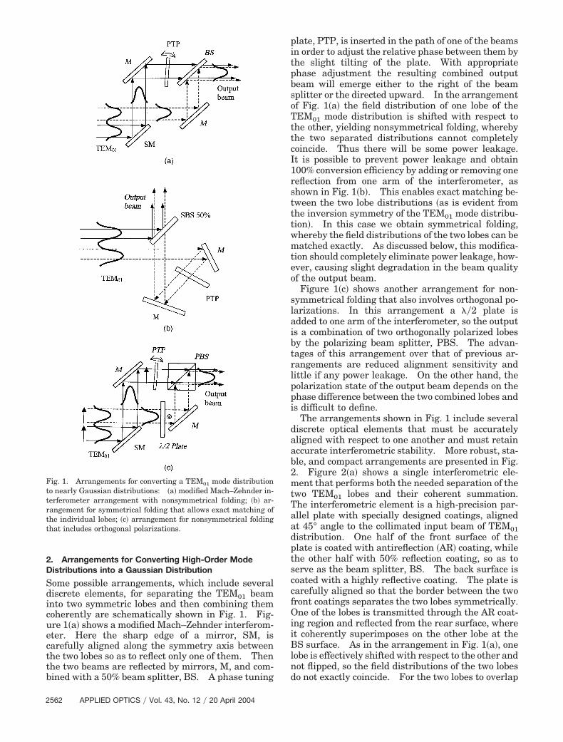
ome possible arrangements, which include severaliscrete elements, for separating the TEM01 beamnto two symmetric lobes and then combining themoherently are schematically shown in Fig. 1. Fig-re 1�a� shows a modified Mach–Zehnder interferom-ter. Here the sharp edge of a mirror, SM, isarefully aligned along the symmetry axis betweenhe two lobes so as to reflect only one of them. Thenhe two beams are reflected by mirrors, M, and com-ined with a 50% beam splitter, BS. A phase tuning
ig. 1. Arrangements for converting a TEM01 mode distributiono nearly Gaussian distributions: �a� modified Mach–Zehnder in-erferometer arrangement with nonsymmetrical folding; �b� ar-angement for symmetrical folding that allows exact matching ofhe individual lobes; �c� arrangement for nonsymmetrical foldinghat includes orthogonal polarizations.
562 APPLIED OPTICS � Vol. 43, No. 12 � 20 April 2004
late, PTP, is inserted in the path of one of the beamsn order to adjust the relative phase between them byhe slight tilting of the plate. With appropriatehase adjustment the resulting combined outputeam will emerge either to the right of the beamplitter or the directed upward. In the arrangementf Fig. 1�a� the field distribution of one lobe of theEM01 mode distribution is shifted with respect to
he other, yielding nonsymmetrical folding, wherebyhe two separated distributions cannot completelyoincide. Thus there will be some power leakage.t is possible to prevent power leakage and obtain00% conversion efficiency by adding or removing oneeflection from one arm of the interferometer, ashown in Fig. 1�b�. This enables exact matching be-ween the two lobe distributions �as is evident fromhe inversion symmetry of the TEM01 mode distribu-ion�. In this case we obtain symmetrical folding,hereby the field distributions of the two lobes can beatched exactly. As discussed below, this modifica-
ion should completely eliminate power leakage, how-ver, causing slight degradation in the beam qualityf the output beam.Figure 1�c� shows another arrangement for non-
ymmetrical folding that also involves orthogonal po-arizations. In this arrangement a ��2 plate isdded to one arm of the interferometer, so the outputs a combination of two orthogonally polarized lobesy the polarizing beam splitter, PBS. The advan-ages of this arrangement over that of previous ar-angements are reduced alignment sensitivity andittle if any power leakage. On the other hand, theolarization state of the output beam depends on thehase difference between the two combined lobes ands difficult to define.
The arrangements shown in Fig. 1 include severaliscrete optical elements that must be accuratelyligned with respect to one another and must retainccurate interferometric stability. More robust, sta-le, and compact arrangements are presented in Fig.. Figure 2�a� shows a single interferometric ele-ent that performs both the needed separation of the
wo TEM01 lobes and their coherent summation.he interferometric element is a high-precision par-llel plate with specially designed coatings, alignedt 45° angle to the collimated input beam of TEM01istribution. One half of the front surface of thelate is coated with antireflection �AR� coating, whilehe other half with 50% reflection coating, so as toerve as the beam splitter, BS. The back surface isoated with a highly reflective coating. The plate isarefully aligned so that the border between the tworont coatings separates the two lobes symmetrically.ne of the lobes is transmitted through the AR coat-
ng region and reflected from the rear surface, wheret coherently superimposes on the other lobe at theS surface. As in the arrangement in Fig. 1�a�, one
obe is effectively shifted with respect to the other andot flipped, so the field distributions of the two lobeso not exactly coincide. For the two lobes to overlap

ot
waTTo
tt�s
lbiThcwcit
orctplltttppNtflficaoaTpiloa
utt
3
Scpec
wosetdwisfixmtFfdt
Fbv
ptimally at a 45° incident angle, the thickness d ofhe plate should obey
2d tan�arcsin1
�2n� � �2x0, (1)
here n is the refraction index of the plate materialnd x0 is the required shift between the two lobes.he relative phase between the two lobes of theEM01 distribution can be adjusted by a slight tiltingf the plate, so their fields are combined coherently.With the plate arrangement it is possible not to do
he AR coating on one half of the plate. In this casehe incident angle should be the Brewster’s angle55.4° for fused silica�, and the incident TEM01 modehould be P polarized.The arrangement for symmetrical folding of the
obes, shown in Fig. 1�b�, can be made more compacty exploiting a special prism, as shown schematicallyn Fig. 2�b�. The incident beam is a pure p-polarizedEM01 mode distribution. The crucial element is aigh-precision 90° prism with specially designedoatings. Half of the prism front surface is coatedith an AR coating, while the other half has a 50% BS
oating. The sharp border between the two coatingss carefully aligned along the symmetry axis betweenhe two lobes of the TEM -mode distribution. One
ig. 2. Compact arrangements for obtaining a nearly Gaussianeam from a TEM01 mode: �a� compact single-plate mode con-erter; �b� compact-prism mode converter.
01
f the lobes is directly transmitted through the ARegion, is totally reflected back, and exits the prismollinearly with the other reflected lobe field, and thewo lobes are coherently combined on the 50% BS. Ahase-tuning plate inserted in the path of one of theobes field adjusts the relative phase between theobes. In order to separate the incident field fromhe output field, the prism can be tilted slightly fromhe vertical orientation. Alternatively, the separa-ion could be achieved with the aid of a PBS and a ��4late before the prism, albeit with some losses due toolarization changes on reflections in the prism.ote that with this arrangement the field distribu-
ion of one lobe is not only shifted but also effectivelyipped with respect to the other. Consequently theeld distributions of the two lobes can completelyoincide, so the power loss is negligible, as in therrangement in Fig. 1�b�. The beam-quality factorf the combined output beam should be Mx
2 � 1.15nd My
2 � 1, as for the one lobe of the TEM01 mode.he advantage of the single-prism converter com-ared with the single-plate converter is the possibil-ty of exactly overlapping the distributions of the twoobes, including the tails, and the consequent absencef the ghost reflections from the AR-coated surfacend other residual reflections.Finally, all the above arrangements can also be
sed to convert a beam with a Gaussian distributiono that of a TEM01 distribution by simply reversinghe direction of the beams.
. Discussion
ince the two distributions of the individual lobes areombined coherently, it is best to have a maximalower P in one direction, so that the transformationfficiency will be maximal. The conversion effi-iency can be written as
C � 1 �
���
�
�U1� x� � U2� x � x0��2dx
2 ���
�
{�U1� x��2 � �U2� x � x0��2}dx
, (2)
here U1�x� and U2�x � x0� are the field distributionsf the two lobes of the TEM01 mode, which have theame phase. The field distribution U2�x � x0� isffectively shifted by the shift parameter x0. Notehat in the arrangements in Figs. 1�b� and 2�b� theistribution U2 is not only shifted but first flippedith respect to U1 �flipped in such a way that the
nitial distance between the peaks remains theame�. Figure 3 shows the calculated conversion ef-ciency as a function of the relative shift parameter0�w, where w is the waist parameter of the TEM01ode. Curve �a� shows the efficiency calculated for
he nonsymmetrical folding arrangement shown inig. 1�a�. Curve �b� shows the efficiency calculated
or the symmetrical folding arrangement with flippedistribution U2, as shown in Fig. 1�b�. As is evident,he maximal efficiency obtained for nonsymmetrical
20 April 2004 � Vol. 43, No. 12 � APPLIED OPTICS 2563

ff�
b
wsttEbxt
sMvtmMMortbtmG
M1mMcmt
bimtrTqchwas�
4
WsdNm
tc6mTTtt
uTcomowt�
Fsimof
Frrm
2
olding arrangements is 98.5% �x0�w � 1.62�, whileor the symmetrical folding arrangement it is 100%x0�w � 1.41�.
Now the beam-quality factor M2 of the combinedeam along the x direction11 is
Mx2 � 4�xsx
, (3)
here x and sxare the near-field and the far-field
tandard deviations of the beam-intensity profile inhe x direction. �The spatial frequency sx is relatedo the propagation angle by sx � sin ��.� Usingq. �2�, we calculated Mx
2 of the combined outputeam as a function of the relative shift parameter0�w. The results are in Fig. 4. Curve �a� showshe beam-quality factor Mx
2 calculated for the non-
ig. 3. Calculated conversion efficiency as function of the relativehift parameter x0�w: �a�, efficiency for the nonsymmetrical fold-ng arrangements in Figs. 1�a� and 1�c�; �b�, efficiency for the sym-
etrical folding arrangement in Fig. 1�b�. The maximal efficiencybtained for nonsymmetrical folding is 98.5% �x0�w � 1.62�, whileor the symmetrical folding it is 100% �x0�w � 1.41�.
ig. 4. Calculated beam-quality factor Mx2 as a function of the
elative shift parameter x0�w: �a�, nonsymmetrical folding ar-angements in Figs. 1�a� and 1�c�; �b�, symmetrical folding arrange-ent in Fig. 1�b�.
564 APPLIED OPTICS � Vol. 43, No. 12 � 20 April 2004
ymmetrical folding arrangement in Fig. 1�a�. Herex2 � 1.045 at the optimal value of x0 � 1.62w, being
ery close to the diffraction limit. Curve �b� showshe beam-quality factor Mx
2 calculated for the sym-etrical folding arrangement of Fig. 1�b�. Herex2 � 1.15 at the optimal value of x0 � 1.41w, as the
x2 value of a single TEM01 lobe. Note that the Mx
2
btained for the optimal nonsymmetrical folding ar-angement is smaller than that obtained for the op-imal symmetrical folding arrangement. This isecause the combined sum of the two lobe distribu-ions is more symmetric and smooth for the nonsym-etrical folding arrangement; hence they resemble aaussian better than each lobe separately.As is evident, there is a significant reduction in thex2 value, from 3 for the TEM01 mode11 to 1.045 or
.15. Since the My2 factor �in the y direction� re-
ains 1, the effective cylindrical M2 value12 will be2 � �Mx
2 � My2��2 � 1.0225 for the nonsymmetri-
al folding arrangement and M2 � 1.075 for the sym-etrical folding arrangement, both comparable with
hat of an ideal Gaussian-beam distribution.The calculated conversion efficiencies and the
eam-quality factors for the compact arrangementsn Fig. 2 are essentially the same. For the arrange-
ent with the single plate in Fig. 2�a�, some part ofhe tail in the transmitted lobe distribution is noteflected back and coherently summed at the output.hus the power loss is reduced, but the output beamuality is somewhat deteriorated. The calculatedonversion efficiency calculated for this arrangementas a maximum of 98.9% at a shift of x0 � 1.6w,here the calculated Mx
2 value is 1.54.13 For therrangement with the prism in Fig. 2�b� the folding isymmetrical and the results are the same as curvesb� in Figs. 3 and 4.
. Experimental Procedure and Results
e experimentally evaluated the arrangements pre-ented in Figs. 1�a�, 2�a�, and 2�b�. The TEM01 modeistribution was derived from either a cw or a pulsedd:YAG laser in which a discontinuous phase ele-ent was inserted into the cavity.1,2
The cw diode-pumped Nd:YAG laser was used withhe conversion arrangement in Fig. 1�a�. The laseronfiguration included a plano–convex �R � 1.5-m�0-cm-long resonator, an intracavity aperture of 1.6m, and a TEM01 mode selecting phase element.he laser was operated with output power of �2 W.he corresponding pump power was close to thehreshold of the laser. The measured focal length ofhe rod due to thermal lensing was �70 cm.
The flashlamp-pumped pulsed Nd:YAG laser wassed with the conversion arrangements in Fig. 2.he laser configuration included a plano–concave 70-m-long resonator �R � 3 m�, an intracavity aperturef 1.9 mm, and a TEM01-mode-selecting phase ele-ent positioned �9 cm from the rear mirror. The
utput beam was P polarized, and the pulse widthas �120 s. The laser operated not far from the
hreshold at a rate of 4 pps, and the output power was60 mW �15 mJ�pulse�. For optimal overlap to be

cTbvtiamdabtfibfluwdsd
5tdsidibr
iiaf
FFtnnr
FFt�n
FFt�n
onveniently obtained between the two lobes of theEM01 distribution with these arrangements, theeam from the laser was externally magnified with aariable zoom telescope so as to be compatible withhe thickness of the mode-converting element and�orn order to collimate the beam. The plate in therrangement shown in Fig. 2�a� had a thickness of 3m and parallelism of 1 arc sec, and appropriate
ielectric coatings for P polarization and was alignedt an approximate angle of 45° relative to the incidenteam. The angle was fine tuned so the field from thewo lobes coherently adds up at the output. Weound that the fine adjustment of the angle had annsignificant effect on the relative transverse shiftetween the lobe distributions. To reduce ghost re-ections from the AR-coated surface and other resid-al reflections, we used a one-dimensional apertureith sharp edges so as to pass only the relevant lightistributions. In the arrangement with the prismhown in Fig. 2�b� we used a prism whose angulareviation from 90° was less than 10 arc sec.The experimental results are presented in Figs.
–7. Figure 5 shows the experimental results ob-ained with the arrangement shown in Fig. 1�a�, alletected with a CCD camera. Figures 5�a� and 5�b�how, respectively, the near-field and the far-fieldntensity distributions of the incident beam that waserived from the cw Nd:YAG laser. The far-fieldntensity distribution was obtained by focusing theeam with a spherical lens � f � 101 cm�. Theseesults indicate that the incident TEM distribution
ig. 5. Experimental results obtained with the arrangement inig. 1�a�: �a�, �b� near-field and far-field intensity distributions ofhe incident TEM01 beam derived from a cw Nd:YAG laser; �c�, �d�ear-field and far-field intensity distributions of the high-quality,early Gaussian output beam. The cross sections in x and y di-ections are shown at the bottom and left sides.
01
s quite pure, with Mx2 � 3.21 and My
2 � 1.1, whichs slightly larger than the theoretical values Mx
2 � 3nd My
2 � 1. Thus it should be possible to trans-orm the distribution into a high-quality nearly
ig. 6. Experimental results obtained with the arrangement inig. 2�a�: �a�, �b� near-field and far-field intensity distributions ofhe incident TEM01 beam derived from a pulsed Nd:YAG laser; �c�,d� near-field and far-field intensity distributions of the combinedearly Gaussian output beam.
ig. 7. Experimental results obtained with the arrangement inig. 2�b�: �a�, �b� near-field and far-field intensity distributions ofhe incident TEM01 beam derived from a pulsed Nd:YAG laser; �c�,d� near-field and far-field intensity distributions of the outputearly Gaussian beam.
20 April 2004 � Vol. 43, No. 12 � APPLIED OPTICS 2565

Gdmonww
tpcctppmsstGt1eaYdoamtb
w6ddcaTsdeAilb
1appiccatrpdwct
w1e
w7fbcatsbffhtct
bbppspfdisctwcfww
atiwiWliGttTuibt8ofiiltw
2
aussian beam. The TEM01 mode was then intro-uced into the arrangement shown in Fig. 1�a�. Theirrors and beam splitter were carefully adjusted for
ptimal overlap of the lobe distributions, both in theear field and far field, and the phase tuning plateas rotated until complete constructive interferenceas obtained at the output.This procedure ensured that the directions of the
wo beams were completely matched, and there is nohase difference between the beams. Note that theoherent summation should be made sufficientlylose to the original beam waist in order to minimizehe wavefront curvature of either beam. In our ex-eriments the optical distance from the output cou-ler was �35 cm, while the Rayleigh distance was �3. The experimental near-field and far-field inten-
ity distributions of the combined output beam arehown in Figs. 5�c� and 5�d�, respectively. Both havehe expected shape of one bright spot with nearlyaussian cross sections in both the x and the y direc-
ions. Using these results, we calculated that Mx2 �
.34 for the output beam, somewhat higher than thexpected value of 1.045. We attribute this discrep-ncy to a possible impurity in the incident beam.et there is reasonable agreement between the pre-icted and experimental results, proving the validityf our approach. We found that the experimentalrrangement in Fig. 1�a� is rather sensitive to theechanical and thermal vibrations and requires con-
inuous control. Typically the optimal output distri-ution was stable for only 20–40 min.Figure 6 shows the experimental results obtainedith the arrangement in Fig. 2�a�. Figures 6�a� and�b� show the near-field and the far-field intensityistributions of the incident TEM01 beam that waserived from a pulsed Nd:YAG laser. The M2 factoralculated for this beam12 was 3.04 in the x directionnd 1.16 in the y direction, indicating a nearly pureEM01 distribution. Figures 6�c� and 6�d� show, re-pectively, the near-field and the far-field intensityistributions of the combined output beam thatmerges from the compact conversion arrangement.s is evident, both the near-field and the far-field
ntensity distributions have a single high-intensityobe with nearly Gaussian profile cross sections inoth axes.Using these results, we calculated values of Mx
2 �.21 and My
2 � 1.05 for the output beam along withtotal measured power efficiency of 91%, i.e., a 9%
ower loss. This indicates that the ratio of theower to Mx
2 � My2 �proportional to the brightness�
s increased by a factor of 2.5 after the conversion andlearly demonstrates that M2 of the output beam isloser to that of TEM00. The 9% power loss can bettributed to the inexact overlap of the fields of thewo-lobe distributions as well as the possible impu-ity of the original TEM01 incident beam, pulse-to-ulse fluctuations of its intensity distribution andirection, and imperfect dielectric coatings. Evenith this loss the results indicate a relatively efficient
onversion to a nearly Gaussian beam. We foundhat the output distribution was much more stable
566 APPLIED OPTICS � Vol. 43, No. 12 � 20 April 2004
ith the arrangement in Fig. 2�a� than that of Fig.�a�. Indeed it remained stable during the entirexperiment �several days�.Figure 7 shows the experimental results obtainedith the arrangement shown in Fig. 2�b�. Figures�a� and 7�b� show the experimental near-field andar-field intensity distributions of the incident TEM01eam derived from a pulsed Nd:YAG laser. The cal-ulated M2 for this beam was 3.09 in the x directionnd 1.16 in the y direction, being very close to theheoretical values of 3 and 1. Figures 7�c� and 7�d�how the near-field and the far-field intensity distri-utions of the combined output beam that emergesrom the mode converter. Both the near- and thear-field intensity distributions consist of a singleigh-intensity lobe with nearly Gaussian cross sec-ions in both directions. Using these results, we cal-ulated that Mx
2 � 1.37 and My2 � 1.39 rather than
he theoretical values of 1.15 and 1.The separation between the input and the output
eam was performed by introducing a polarizingeam splitter and a ��4 plate before the prism. Theower efficiency was measured by replacing therism with a mirror of 99% reflectivity. The mea-ured conversion efficiency was 93%, indicating a 7%ower loss. This loss can be attributed to severalactors: inexact overlap of the fields of the two-lobeistributions, possible impurity of the original TEM01nput beam, pulse-to-pulse fluctuations of its inten-ity distribution and direction, imperfect dielectricoatings, and possible rotations of the polarization onhe total internal reflections in the prism. Evenith this loss these results indicate a relatively effi-
ient conversion to a nearly Gaussian beam. Weound that the stability of the output distributionith the arrangement in Fig. 2�b� was comparableith that of Fig. 2�a�.All the proposed conversion arrangements can
lso be used to convert a Gaussian-beam distribu-ion to that of a TEM01 distribution, simply revers-ng the direction of the beams. To illustrate this,e performed an experiment with the single-
nterferometric-element arrangement in Fig. 2�a�.e used a Gaussian beam derived from an Nd:YAG
aser and reversed the direction of propagationn the conversion arrangement. Specifically, theaussian beam was incident at the BS interface of
he plate converter, and the output TEM01 distribu-ion emerged from the AR-coated and BS interfaces.he experimental results are shown in Fig. 8. Fig-res 8�a� and 8�b� show the near-field and the far-field
ntensity distributions of the incident Gaussianeam. Figure 8�c� shows the near-field intensity dis-ribution of the output TEM01 distribution. Figure�d� shows the far-field intensity distribution of theutput TEM01 beam distribution, when the two near-eld lobes have the same phase. As expected, there
s a bright central lobe with two low-intensity side-obes. Figure 8�e� shows the far-field intensity dis-ribution of the output TEM01 beam distribution,hen the two near-field lobes have a � phase shift �a

rc
5
Wettmmafmew
psdbGcip
cora
V
R
1
1
1
1
Fdmtdbno
eal TEM01 mode distribution�. The phase-shiftontrol is achieved by carefully tilting the plate.
. Concluding Remarks
e have presented several optical arrangements forfficiently converting a high-order TEM01 distribu-ion into a nearly Gaussian-beam distribution,hereby improving beam quality. These arrange-ents have included several discrete optical ele-ents and some more compact and robust
rrangements with a single specially coated inter-erometric element. Several conversion arrange-
ents have been experimentally evaluated, and thexperimental results were close to those predicted,
ig. 8. Conversion of a Gaussian distribution into a TEM01 modeistribution by using the single-interferometric-element arrange-ent in Fig. 2�a�: �a�, �b� near-field and far-field intensity distribu-
ions of the incident Gaussian beam; �c� near-field intensityistribution of the TEM01 output beam; �d� far-field intensity distri-ution of the TEM01 output beam when the phase of each lobe in theear field is the same; �e� far-field intensity distribution of the TEM01
utput beam with a conventional TEM01 phase distribution.
ith conversion efficiencies greater than 90%. It is
ossible to extend the arrangements to allow conver-ion of higher-order-mode distributions to a Gaussianistribution. For example, the TEM02 mode distri-ution, which is composed of four identical nearlyaussian lobes and having Mx
2 � My2 � 3,12 can be
onverted to a single Gaussian distribution by resort-ng to double and folded arrangements in the twoerpendicular directions.Finally, we can also exploit all the arrangements to
onvert a single Gaussian distribution into a high-rder mode distribution by simply reversing the di-ection of the light propagation in the conversionrrangements.
This research was supported in part by Parnotenture Capital Fund through Impala, Ltd.
eferences1. R. Oron, N. Davidson, A. A. Friesem, and E. Hasman, “Trans-
verse mode shaping and selection in laser resonators,” Prog.Opt. 42, 325–385 �2001�.
2. A. A. Ishaaya, N. Davidson, G. Machavariani, E. Hasman, andA. A. Friesem, “Efficient selection of high-order Laguerre–Gaussian modes in a Q-switched Nd:YAG laser,” J. QuantumElectron. 39, 74–82 �2003�.
3. A. A. Napartovich, N. N. Elkin, V. N. Troschieva, D. V. Vy-sotsky, and J. R. Leger, “Simplified intracavity phase plates forincreasing laser-mode discrimination,” Appl. Opt. 38, 3025–3029 �1999�.
4. M. Gerber and T. Graf, “Generation of super-Gaussian modesin Nd:YAG lasers with graded-phase mirrors,” in Proceedingsof International Conference on Advanced Laser Technologies,15–20 September 2002, Adelboden, Switzerland, pp. 3–4.
5. T. Graf and J. E. Balmer, “Laser beam quality, entropy and thelimits of beam shaping,” Opt. Commun. 131, 77–83 �1996�.
6. P. W. Rhodes and D. L. Shealy, “Refractive optical systems forirradiance redistribution of collimated radiation: their designand analysis,” Appl. Opt. 20, 3545–3553 �1980�.
7. O. Bryngdahl, “Geometrical transformations in optics,” J. Opt.Soc. Am. 64, 1092–1099 �1974�.
8. M. T. Eismann, A. M. Tai, and J. N. Cederquist, “Iterativedesign of a holographic beamformer,” Appl. Opt. 28, 2641–2650�1989�.
9. N. Davidson, A. A. Friesem, and E. Hasman, “Diffractive ele-ments for annular laser beam transformation,” Appl. Phys.Lett. 61, 381–383 �1992�.
0. G. Machavariani, N. Davidson, A. A. Ishaaya, A. A. Friesem,and E. Hasman, “Efficient formation of a high-quality beamfrom a pure high-order Hermite–Gaussian mode,” Opt. Lett.27, 1501–1503 �2002�.
1. A. E. Siegman, “New developments in laser resonators,” inOptical Resonators, D. A. Holmes, ed., Proc. SPIE 1224, 2–14�1990�.
2. J. B. Murphy, “Phase space conservation and selection rulesfor astigmatic mode converters,” Opt. Commun. 165, 11–18�1999�.
3. A. A. Ishaaya, G. Machavariani, N. Davidson, A. A. Friesem,and E. Hasman, “Conversion of a high-order mode beam into anearly Gaussian beam using a single interferometric element,”
Opt. Lett. 28, 504–506 �2003�.20 April 2004 � Vol. 43, No. 12 � APPLIED OPTICS 2567