Efficient inter-trap transfer of cold francium...
6
Hyperfine Interact (2016) 237:150 DOI 10.1007/s10751-016-1347-9 Efficient inter-trap transfer of cold francium atoms J. Zhang 1 · R. Collister 2 · K. Shiells 2 · M. Tandecki 3 · S. Aubin 4 · J. A. Behr 3 · E. Gomez 5 · A. Gorelov 3 · G. Gwinner 2 · L. A. Orozco 1 · M. R. Pearson 3 · Y. Zhao 6 © Springer International Publishing Switzerland 2016 Abstract We report on the status of the FrPNC experiments and summarize our plans for measurements of parity non-conservation (PNC) in a sample of cold francium. The FrPNC collaboration has commissioned a laser cooling apparatus at the TRIUMF accelerator that collects and cools francium atoms for PNC experiments. We have recently demonstrated the robust, high efficiency transfer (50 %) of laser cooled francium atoms to a second laser cooling apparatus, located 0.7 m below the first, where the PNC experiments will be conducted. Keywords Laser cooling · Atom trap · Instrumentation for radioactive beams This article is part of the Topical Collection on Proceedings of the 6th International Symposium on Symmetries in Subatomic Physics (SSP 2015), Victoria, Canada, 8-12 June 2015 Edited by Michael Gericke and Gerald Gwinner S. Aubin [email protected] 1 Department of Physics, Joint Quantum Institute, University of Maryland and National Institute of Standards and Technology, College Park, MD 20742, USA 2 Department of Physics and Astronomy, University of Manitoba, Winnipeg, Manitoba, R3T 2N2, Canada 3 TRIUMF, Vancouver, British Columbia, V6T2A3, Canada 4 Department of Physics, College of William and Mary, Williamsburg, VA 23187, USA 5 Instituto de F´ ısica, Universidad Aut´ onoma de San Luis Potos´ ı, San Luis Potos´ ı 78290, M´ exico 6 State Key Laboratory of Quantum Optics and Quantum Optics Devices, Institute of Laser Spectroscopy, Shanxi University, Taiyuan 030006, China
Transcript of Efficient inter-trap transfer of cold francium...
Hyperfine Interact (2016) 237:150 DOI 10.1007/s10751-016-1347-9
Efficient inter-trap transfer of cold francium atoms
J. Zhang1 ·R. Collister2 ·K. Shiells2 ·M. Tandecki3 ·S. Aubin4 · J. A. Behr3 ·E. Gomez5 ·A. Gorelov3 ·G. Gwinner2 ·L. A. Orozco1 ·M. R. Pearson3 ·Y. Zhao6
© Springer International Publishing Switzerland 2016
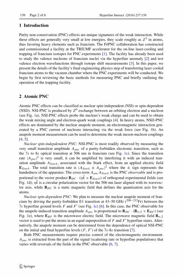
Abstract We report on the status of the FrPNC experiments and summarize our plans formeasurements of parity non-conservation (PNC) in a sample of cold francium. The FrPNCcollaboration has commissioned a laser cooling apparatus at the TRIUMF accelerator thatcollects and cools francium atoms for PNC experiments. We have recently demonstratedthe robust, high efficiency transfer (50 %) of laser cooled francium atoms to a secondlaser cooling apparatus, located 0.7 m below the first, where the PNC experiments will beconducted.
Keywords Laser cooling · Atom trap · Instrumentation for radioactive beams
This article is part of the Topical Collection on Proceedings of the 6th International Symposium onSymmetries in Subatomic Physics (SSP 2015), Victoria, Canada, 8-12 June 2015Edited by Michael Gericke and Gerald Gwinner
� S. [email protected]
1 Department of Physics, Joint Quantum Institute, University of Maryland and National Instituteof Standards and Technology, College Park, MD 20742, USA
2 Department of Physics and Astronomy, University of Manitoba,Winnipeg, Manitoba, R3T 2N2, Canada
3 TRIUMF, Vancouver, British Columbia, V6T 2A3, Canada
4 Department of Physics, College of William and Mary, Williamsburg, VA 23187, USA
5 Instituto de Fısica, Universidad Autonoma de San Luis Potosı, San Luis Potosı 78290, Mexico
6 State Key Laboratory of Quantum Optics and Quantum Optics Devices, Institute of LaserSpectroscopy, Shanxi University, Taiyuan 030006, China
150 Page 2 of 6 Hyperfine Interact (2016) 237:150
1 Introduction
Parity non-conservation (PNC) effects are unique signatures of the weak interaction. Whilethese effects are generally very small at low energies, they scale roughly as Z3 in atoms,thus favoring heavy elements such as francium. The FrPNC collaboration has constructedand commissioned a facility at the TRIUMF accelerator for the on-line laser-cooling andtrapping of francium isotopes for PNC experiments [1]. The facility has already been usedto study the valence nucleons of francium nuclei via the hyperfine anomaly [2] and testvalence electron wavefunctions through isotope shift measurements [3]. In this paper, wepresent the details of the facility’s final engineering physics step of transferring laser cooledfrancium atoms to the vacuum chamber where the PNC experiments will be conducted. Webegin by first reviewing the basic methods for measuring PNC and briefly outlining theoperation of the trapping facility.
2 Atomic PNC
Atomic PNC effects can be classified as nuclear spin-independent (NSI) or spin-dependent(NSD). NSI-PNC is produced by Z0 exchange between an orbiting electron and a nucleon(see Fig. 1a). NSI-PNC effects probe the nucleus’s weak charge and can be used to obtainthe weak mixing angle and electron-quark weak couplings [4]. In heavy atoms, NSD-PNCeffects are dominated by the nuclear anapole moment, an electromagnetic interaction gen-erated by a PNC current of nucleons interacting via the weak force (see Fig. 1b). Ananapole moment measurement can be used to determine the weak meson-nucleon couplings[4, 5].
Nuclear spin-indepdendent PNC: NSI-PNC is most readily observed by measuring thevery small transition amplitude Apnc of a parity-forbidden electronic transition, such asthe 7s to 8s optical transition at 506 nm in francium (see Fig. 1c). Since the transitionrate |Apnc|2 is very small, it can be amplified by interfering it with an induced tran-sition amplitude AStark , associated with the Stark effect, from an applied electric fieldEStark . The total transition rate is |AStark ± Apnc|2 where the ± sign represents thehandedness of the apparatus: The cross-term ApncAStark is the PNC observable and is pro-portional to the vector product BDC · (ηk × EStark) of orthogonal experimental fields (seeFig. 1d); ηk is a circular polarization vector for the 506 nm laser aligned with its wavevec-tor axis, while BDC is a static magnetic field that defines the quantization axis for theatoms.
Nuclear spin-dependent PNC: We plan to measure the nuclear anapole moment of fran-cium by driving the parity-forbidden E1 transition at 43–50 GHz (208−212Fr) between the7s hyperfine ground levels F and F ′ (see Fig. 1c) [6]. In this case, the PNC observable forthe anapole-induced transition amplitude Apnc is proportional to BDC · (Bπ/2 × ERF ) (seeFig. 1e), where ERF is the microwave electric field. The microwave magnetic field Bπ/2vector is used to put the atoms in an equal superposition of F and F ′ hyperfine states. Alter-natively, the anapole moment can be determined from the dependence of optical NSI-PNCon the initial and final hyperfine levels (F , F ′) of the 7s-8s transition [7].
Both PNC measurements require precise control of the electromagnetic environment.Apnc is extracted from the part of the signal (scattering rate or hyperfine populations) thatvaries with reversals of the fields in the PNC observable [6, 7].

Hyperfine Interact (2016) 237:150 Page 3 of 6 150
Fig. 1 Atomic parity non-conservation. a Nuclear spin-independent PNC (NSI-PNC): An axial-vector elec-tron current Ae exchanges a Z0 boson with a vector nucleon current VN . b Nuclear spin-dependent PNC(NSD-PNC): A vector electron interacts electromagnetically (γ -photon exchange) with the anapole momentof the nucleus. c atomic Fr transitions for PNC experiments: NSI-PNC can be measured by driving the 7s-8s parity-forbidden E1 transition at 506 nm; NSD-PNC can be probed by driving a parity-forbidden E1transition between the hyperfine levels (F ↔ F ′) of the 7s ground level (43–50 GHz). d, e External electro-magnetic field vectors define a coordinate system, whose handedness determines the sign of the PNC signalfor the d optical NSI-PNC and e microwave NSD-PNC anapole moment experiments
3 Francium trapping facility
The Francium Trapping Facility (FTF) is a rf-shielded laser spectroscopy lab in the ISACI hall at TRIUMF. The FTF houses the laser cooling and trapping apparatus for the opti-cal PNC and anapole moment experiments, as well as the lasers, instruments, and controlsystems to operate it. We describe it briefly here, and refer the reader to reference [1] fordetails. Figure 2a shows the laser cooling and trapping apparatus, which consists of twomagneto-optical traps (MOTs). The ISAC facility at TRIUMF delivers up to 109 Fr/s to theFTF. The capture MOT (top MOT in Fig. 2a) cools and traps francium delivered to the FTF,while the science MOT (bottom MOT in Fig. 2a) provides a laser cooled Fr sample withinthe multi-use, high-access vacuum chamber (science chamber) for the PNC experiments.Both MOTs trap with light on the D2 line at 718 nm with repumping on the D1 (817 nm)or D2 line (see Fig. 1c). Notably, the apparatus is frequently operated off-line with rubid-ium (D2: 780 nm, D1: 795 nm). The vacuum systems for the two MOTs are located directlyabove one another and connected by a differential pumping tube through which laser cooledatoms can be transferred.
Transfer tube This tube connects the vacuum systems for the two MOTs and includes agate valve for venting either end separately, a shutter for quickly isolating the two vacuumchambers, and viewports for optical access to transiting atoms.
Capture MOT This MOT is optimized for maximum trapping efficiency and has success-fully trapped nine isotopes (206−213,221Fr) [1–3]. This MOT features large trapping beams(for a high capture velocity) that fill most of the Pyrex vacuum cell of the MOT to optimizethe trapping volume. The inside of the cell is coated with a dry-film [8] to re-thermalizeand then release physisorbed Fr atoms back into the trapping volume. Neutral Fr atoms are

150 Page 4 of 6 Hyperfine Interact (2016) 237:150
Fig. 2 Laser cooling and trapping apparatus and transfer results. a Capture MOT (up), science MOT (down)and connecting transfer tube. Fr+ ions are collected on a two-position yttrium neutralizer (vertical and hori-zontal red segments), which releases neutral atoms when heated. Both MOTs consist of six laser beams (fourare shown as red arrows) and an anti-Helmholtz coil (capture MOT: orange dots indicate coil currents). Cap-ture MOT atoms are transferred to the science chamber MOT by a laser (purple arrow) that pushes themdownwards. Parts b–d use a common time axis to detail the transfer of capture MOT Fr atoms to the scienceMOT. b The fluorescence of the capture MOT shows the initial trapping of 211Fr atoms released from theneutralizer, and their transfer at t = 0 to the science MOT. c The timing diagrams show the order of opera-tion for the neutralizer (orientation and heating), the capture MOT beams, science MOT beams, and transferpulse (purple). d The fluorescence of the science MOT shows the trapping of 211Fr atoms transferred fromthe capture MOT at t = 0 (only 18 s of the 36 s experimental cycle are shown). The transfer efficiency forthe data in (b, d) is 52 %. Inset in (d): A 20 cycle histogram of transfer efficiency
dispensed into the capture cell by a 2-position yttrium neutralizer: in its downward position(for 20 s or more), the neutralizer collects 20 keV Fr+ ions delivered into the FTF via anISAC beamline, while in its upward position, the neutralizer releases neutral Fr atoms whenheated for 1 s. While the capture MOT features efficient trapping [1, 8], it is not suitablefor PNC experiments given its poor optical access, modest vacuum, and imprecise controlof electric and magnetic fields.
Science MOT This MOT is located 0.7 m below the capture MOT and is optimized for thePNC experiments. It operates within a large vacuum chamber with excellent optical access(30 vacuum ports of various sizes) and sufficient volume to house electric field plates and anoptical cavity, or a microwave cavity. The vacuum chamber is constructed of low magneticpermeability steel (316L for the body and 316LN for the flanges) to minimize residualmagnetization.

Hyperfine Interact (2016) 237:150 Page 5 of 6 150
Fig. 3 Accumulation of Fr atoms in the science MOT. The plot shows seven transfers of atoms from thecapture MOT. The first transfer is similar to the one in Fig. 2, while the last six transfers are accumulated inthe science MOT. Each transfer cycle is 36 s. blue curve: Capture MOT fluorescence (right axis). red curve:Science MOT fluorescence (left axis). The experimental cycle and timing is similar to that in Fig. 2b–d,except that the science MOT is never turned off, though its laser power is reduced (i.e. the “low” setting inFig. 2c, which causes a drop in fluorescence) when the capture MOT is on
4 Efficient transfer demonstration
We use a push beam to transfer 211Fr atoms from the capture MOT to the science MOTwith an efficiency of 50 %. Figure 2c shows the basic timing of our method. After sufficientatoms have been collected on the neutralizer, the atoms are released into the cell and trappedby the capture MOT. The neutralizer is then swung to its downward position (unblocking thecell exit), the transfer tube shutter is opened, and the trapping beams for the capture MOTare turned off. We then apply a downward-directed, near-resonant laser beam to the atoms(trapping transition at 718 nm) for 10 ms to push the atoms towards the science chamber.
We operate both MOTs with trapping beams of the same intensity, so that the ratio of thefluorescence of the two MOTs is identical to the ratio of the MOT populations. Two nearlyidentical imaging systems monitor the MOTs. Figure 2b and d show the capture MOT andscience MOT fluorescence recorded by the two cameras. The timing sequence also includesperiods when the MOTs contain no atoms, thus generating background signals. We findthat our transfer efficiency is about 0.5 with a spread of about ±0.1. The inset in Fig. 2dshows a histogram of 20 transfers. Our transfer scheme has an efficiency approaching 0.8for 85Rb. The anti-Helmholtz coils of the MOTs are not adjusted dynamically during thetransfer, though we do optimize the magnetic gradient of the science MOT. After geomet-ric alignment of the push beam, we position the capture MOT atoms for optimal transfer bytrimming the magnetic bias fields. Briefly boosting the laser power and ramping the laserdetuning for up to 100 ms to help “catch” the atoms provides little improvement. Once opti-mized, the transfer is quite robust and is not particularly sensitive to any of the experimentalparameters.
Multiple transfers can be loaded cumulatively into the science MOT. Figure 3 showsthe accumulation of atoms in the science MOT over the course of six transfers. We use asimilar timing sequence to that in Fig. 2c but leave the science MOT on throughout the

150 Page 6 of 6 Hyperfine Interact (2016) 237:150
experimental cycle. Importantly, we find that the push beam does not harm the scienceMOT population. The accumulation of multiple transfers is essential for maximizing the Frpopulation available for PNC experiments. The science MOT decay constant for the datashown in Fig. 3 is τ = 41(4) s, which is considerably smaller than the radioactive 1/e
lifetime of 211Fr (τ = 4.5 min). Improving the vacuum of the science chamber shouldlengthen the science MOT lifetime and increase the number of accumulated atoms.
5 Outlook
The efficient transfer of Fr atoms to the science MOT sets the stage for future PNC experi-ments. The science MOT also enables a host of supporting spectroscopy measurements thatrely on good optical (and microwave) access and precise control of electric and magneticfields. For example, planned measurements include the 7s hyperfine splitting and the Starkeffect for the 7s-8s transition.
Acknowledgments The authors thank the TRIUMF/ISAC francium production team and gratefullyacknowledge support by CONACYT, Fundacion Marcos Moshinsky, DOE, Fulbright, NSF, NSERC, andTRIUMF.
References
1. Tandecki, M., Zhang, J., Collister, R., Aubin, S., Behr, J.A., Gomez, E., Gwinner, G., Orozco, L.A.,Pearson, M.R.: J. Instrum. 8, P12006 (2013)
2. Zhang, J., Tandecki, M., Collister, R., Aubin, S., Behr, J.A., Gomez, E., Gwinner, G., Orozco, L.A.,Pearson, M.R., Sprouse, G.D.: Phys. Rev. Lett. 115, 042501 (2015)
3. Collister, R., Gwinner, G., Tandecki, M., Behr, J.A., Pearson, M.R., Zhang, J., Orozco, L.A., Aubin, S.,Gomez, E.: Phys. Rev. A 90, 052502 (2014)
4. Behr, J.A., Gwinner, G.: J. Phys. G: Nucl. Part. Phys. 36, 033101 (2009)5. Haxton, W., Holstein, B.: Prog. Part. Nucl. Phys. 71, 185 (2013)6. Gomez, E., Aubin, S., Sprouse, G.D., Orozco, L.A., DeMille, D.P.: Phys. Rev. A 75, 033418 (2007)7. Wood, C.S., Bennett, S.C., Cho, D., Masterson, B.P., Roberts, J.L., Tanner, C.E., Wieman, C.E.: Science
275, 1759 (1997)8. Aubin, S., Gomez, E., Orozco, L.A., Sprouse, G.D.: Rev. Sci. Instrum. 74, 4342 (2003)